Huawei FusionModule2000 Installation Manual
Smart modular data center 2000 mmhigh cabinets, dual-row aisle containment, 208 v
Hide thumbs
Also See for FusionModule2000:
- Installation manual (318 pages) ,
- Product description (217 pages) ,
- Maintenance manual (144 pages)

Related Manuals for Huawei FusionModule2000


Summary of Contents for Huawei FusionModule2000
- Page 1 FusionModule2000 Smart Modular Data Center V500R002 Installation Guide (2000 mm High Cabinets, Dual-Row Aisle Containment, 208 V) Issue Date 2017-07-30 HUAWEI TECHNOLOGIES CO., LTD.
- Page 2 Notice The purchased products, services and features are stipulated by the contract made between Huawei and the customer. All or part of the products, services and features described in this document may not be within the purchase scope or the usage scope. Unless otherwise specified in the contract, all statements, information, and recommendations in this document are provided "AS IS"...
-
Page 3: About This Document
FusionModule2000 Smart Modular Data Center Installation Guide (2000 mm High Cabinets, Dual-Row Aisle Containment, 208 V) About This Document About This Document Purpose This document describes how to install the smart modular data center (smart module for short) in the dual-row aisle containment scenario. - Page 4 FusionModule2000 Smart Modular Data Center Installation Guide (2000 mm High Cabinets, Dual-Row Aisle Containment, 208 V) About This Document Symbol Description Calls attention to important information, best practices and tips. NOTE is used to address information not related to personal injury, equipment damage, and environment deterioration.
-
Page 5: Table Of Contents
FusionModule2000 Smart Modular Data Center Installation Guide (2000 mm High Cabinets, Dual-Row Aisle Containment, 208 V) Contents Contents About This Document ........................ii 1 Installation Preparations ......................1 1.1 Transportation and Placing Precautions ........................1 1.2 Unpacking and Acceptance ............................2 1.3 Installation Environment Requirements ........................ - Page 6 FusionModule2000 Smart Modular Data Center Installation Guide (2000 mm High Cabinets, Dual-Row Aisle Containment, 208 V) Contents 3.2.7 Cable Specifications ..............................38 3.2.8 (Engineering Procurement) Water Softener ......................40 3.2.9 Checking the Air Pressure ............................40 3.3 Removing Pallets ................................ 42 3.3.1 Unpacking and Checking ............................
- Page 7 FusionModule2000 Smart Modular Data Center Installation Guide (2000 mm High Cabinets, Dual-Row Aisle Containment, 208 V) Contents 7 (Optional) Installing Cable Troughs ..................116 7.1 Installing a 600 mm Wide Cable Trough ........................116 7.2 Installing a 300 mm Wide Cable Trough ........................120 7.3 Installing an 800 mm Wide Cable Trough ........................
- Page 8 13.3 Commissioning the Cooling System ........................211 13.4 Commissioning the Management System ....................... 211 A Appendix ........................... 213 A.1 Contacting Huawei Technical Support ........................213 A.2 Installing Expansion Sleeves ........................... 213 A.3 Installing a Floating Nut ............................214 A.4 Scenario with a Column (600 mm Wide IT Cabinets Scenario) ................215 A.4.1 Scenario Description .............................
- Page 9 FusionModule2000 Smart Modular Data Center Installation Guide (2000 mm High Cabinets, Dual-Row Aisle Containment, 208 V) Contents A.4.6 Installing Cable Trays ............................233 A.4.7 Installing Sealing Plates Away from the Aisle ...................... 236 A.5 Installing a Dehumidifier ............................237 A.6 (Optional) Connecting Cables to Industrial Connectors ..................242 A.7 (Optional) Connecting PDU2000 Cables .........................
-
Page 10: Installation Preparations
FusionModule2000 Smart Modular Data Center Installation Guide (2000 mm High Cabinets, Dual-Row Aisle Containment, 208 V) 1 Installation Preparations Installation Preparations 1.1 Transportation and Placing Precautions Air Conditioner Transportation Precautions Only trained personnel are allowed to move the cabinet. Use a pallet truck to transport the cabinet secured to a wooden support to the installation position. -
Page 11: Unpacking And Acceptance
Step 1 Unpack the carton labeled "Contain Packing List" and take out the Packing List. Step 2 Check all items against the Packing List. Step 3 If an item is incorrect or missing, contact Huawei technical support. Step 4 If any item is damaged, fill in the Cargo Replacement Application Form and report it. -
Page 12: Installation Environment Requirements
FusionModule2000 Smart Modular Data Center Installation Guide (2000 mm High Cabinets, Dual-Row Aisle Containment, 208 V) 1 Installation Preparations Step 5 Sign on the Packing List with the customer after verifying that all required items are delivered. Step 6 Store the items properly. - Page 13 ECC collector, the camera, and the VCN respectively. NOTE An IP address is required for each camera. If any of the requirements is not met, contact Huawei technical support. Issue 01 (2017-07-30) Huawei Proprietary and Confidential Copyright © Huawei Technologies Co., Ltd.
-
Page 14: Site Requirements
FusionModule2000 Smart Modular Data Center Installation Guide (2000 mm High Cabinets, Dual-Row Aisle Containment, 208 V) 1 Installation Preparations 1.4 Site Requirements Equipment Room Height Requirement Figure 1-3 shows the height of a smart module in dual-row aisle containment if 2000 mm high cabinets are used. - Page 15 FusionModule2000 Smart Modular Data Center Installation Guide (2000 mm High Cabinets, Dual-Row Aisle Containment, 208 V) 1 Installation Preparations Figure 1-3 smart module height Cabinet height L1: 2000 mm Open-skylight height L2: 550 mm Smart module layout requirement Figure 1-4 shows the layout requirement for the smart module.
-
Page 16: Tools And Instruments
FusionModule2000 Smart Modular Data Center Installation Guide (2000 mm High Cabinets, Dual-Row Aisle Containment, 208 V) 1 Installation Preparations 1.5 Tools and Instruments This section lists the tools and instruments required for installation. Table 1-3 General tools Name, Specifications, and Appearance... - Page 17 FusionModule2000 Smart Modular Data Center Installation Guide (2000 mm High Cabinets, Dual-Row Aisle Containment, 208 V) 1 Installation Preparations Name, Specifications, and Appearance Laser locator Utility knife Electrician's knife Impact tool Polyvinyl chloride Needle-nose pliers Diagonal pliers RJ45 crimping tool...
- Page 18 FusionModule2000 Smart Modular Data Center Installation Guide (2000 mm High Cabinets, Dual-Row Aisle Containment, 208 V) 1 Installation Preparations Name, Specifications, and Appearance Adjustable socket Flashlight Clamp meter Phase sequence screwdriver meter NOTE This table may not list some tools required at specific sites. Onsite installation personnel and technical support personnel should prepare tools based on site requirements.
- Page 19 FusionModule2000 Smart Modular Data Center Installation Guide (2000 mm High Cabinets, Dual-Row Aisle Containment, 208 V) 1 Installation Preparations Tool Appearance, Specifications, and Name Pipe bender Pipe expander Pressure gauge (2 Leather hose (5 PCS) PCS) Thermocouple Vacuum pump Antifreeze gloves...
-
Page 20: Tools Delivered With Equipment
FusionModule2000 Smart Modular Data Center Installation Guide (2000 mm High Cabinets, Dual-Row Aisle Containment, 208 V) 1 Installation Preparations Tool Appearance, Specifications, and Name a: For equipment with humidifiers, ensure that the water pipe thread sealant is able to resist temperatures higher than 85°... - Page 21 FusionModule2000 Smart Modular Data Center Installation Guide (2000 mm High Cabinets, Dual-Row Aisle Containment, 208 V) 1 Installation Preparations Figure 1-5 Marking-off template for a 1100 mm deep cabinet Figure 1-6 Marking-off template for a 1200 mm deep cabinet Issue 01 (2017-07-30) Huawei Proprietary and Confidential Copyright ©...
- Page 22 FusionModule2000 Smart Modular Data Center Installation Guide (2000 mm High Cabinets, Dual-Row Aisle Containment, 208 V) 1 Installation Preparations Figure 1-7 Usage of marking-off templates (A) Properly located cabinet (B) Marking-off template edgefold Aisle Check Tool Aisle check tool dimension description: ...
-
Page 23: Personnel Requirements
Only trained and qualified personnel who fully understand basic safety precautions are allowed to install and operate a modular data center. Huawei will not be liable for any consequence caused by the violation of this document. The requirements are as follows: ... - Page 24 FusionModule2000 Smart Modular Data Center Installation Guide (2000 mm High Cabinets, Dual-Row Aisle Containment, 208 V) 1 Installation Preparations Figure 1-9 Installation process Issue 01 (2017-07-30) Huawei Proprietary and Confidential Copyright © Huawei Technologies Co., Ltd.
-
Page 25: Scenario Description
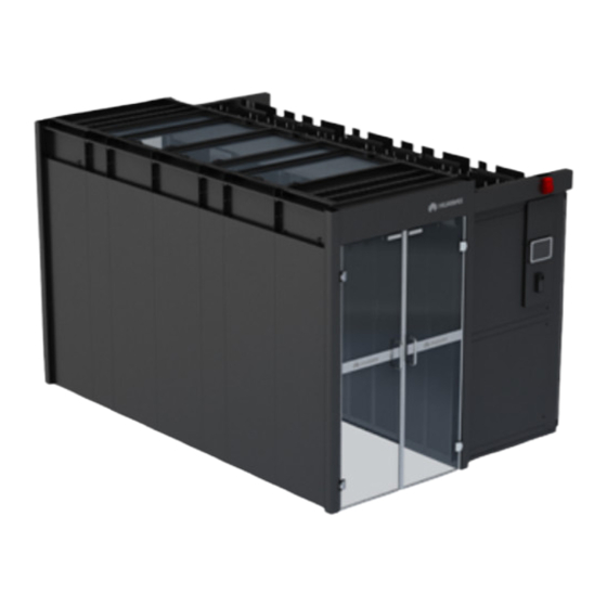
FusionModule2000 Smart Modular Data Center Installation Guide (2000 mm High Cabinets, Dual-Row Aisle Containment, 208 V) 2 Scenario Description Scenario Description Figure 2-1 shows the floor plan of the smart module A dual-row aisle containment. The PDC is an integrated UPS. - Page 26 FusionModule2000 Smart Modular Data Center Installation Guide (2000 mm High Cabinets, Dual-Row Aisle Containment, 208 V) 2 Scenario Description Figure 2-1 Floor plan of a dual-row cold aisle containment (with 1200 mm deep IT cabinets) Figure 2-2 Exterior of the dual-row aisle containment...
-
Page 27: Hardware Installation Preparations
For detailed dimensions requirements for bases, click Download. If you do not use the bases provided by Huawei, design the bearing requirements for bases according to the service plan. -
Page 28: Installing A Cabinet Base
FusionModule2000 Smart Modular Data Center Installation Guide (2000 mm High Cabinets, Dual-Row Aisle Containment, 208 V) 3 Hardware Installation Preparations Figure 3-1 Base layout (unit: mm) 3.1.1.2 Installing a Cabinet Base 3.1.1.2.1 Assembling a Base Before installing a base, assemble it first. - Page 29 FusionModule2000 Smart Modular Data Center Installation Guide (2000 mm High Cabinets, Dual-Row Aisle Containment, 208 V) 3 Hardware Installation Preparations Figure 3-2 Measuring the floor height Adjust the base height to H based on the measured value, as shown by (1) in Figure 3-3.
-
Page 30: Positioning Bases
FusionModule2000 Smart Modular Data Center Installation Guide (2000 mm High Cabinets, Dual-Row Aisle Containment, 208 V) 3 Hardware Installation Preparations Figure 3-4 Assembling a base Adjust the base depth based on the cabinet depth. Tighten the six M8x20 bolt assemblies on the telescopic rod using a Phillips screwdriver,... - Page 31 FusionModule2000 Smart Modular Data Center Installation Guide (2000 mm High Cabinets, Dual-Row Aisle Containment, 208 V) 3 Hardware Installation Preparations Figure 3-5 Using a laser locator for positioning in the two-row cabinet scenario (1) Cabinet outline (2) Contained aisle (3) Laser locator...
-
Page 32: Securing Bases
FusionModule2000 Smart Modular Data Center Installation Guide (2000 mm High Cabinets, Dual-Row Aisle Containment, 208 V) 3 Hardware Installation Preparations Figure 3-7 Positioning combined bases Step 7 Check that L1, L2, L3, and L4 meet the following requirements: |L1–L2| ≤ 5 mm and |L3–L4| ≤... - Page 33 FusionModule2000 Smart Modular Data Center Installation Guide (2000 mm High Cabinets, Dual-Row Aisle Containment, 208 V) 3 Hardware Installation Preparations Procedure Step 1 Move away the base and install expansion bolts, as shown in Figure 3-9. Figure 3-9 Installing an expansion bolt (unit: mm) Step 2 Measure the hole depths and distances.
-
Page 34: Installing Fixed-Size Bases
FusionModule2000 Smart Modular Data Center Installation Guide (2000 mm High Cabinets, Dual-Row Aisle Containment, 208 V) 3 Hardware Installation Preparations Figure 3-11 Connecting bases ----End Result After securing bases, ensure that adjacent bases are in close contact with each other and the gap is even. - Page 35 FusionModule2000 Smart Modular Data Center Installation Guide (2000 mm High Cabinets, Dual-Row Aisle Containment, 208 V) 3 Hardware Installation Preparations When deploying the base, place the side marked FRONT facing the aisle containment. After deploying the base, check that the adjustable feet for the base should be installed at the front door of the air conditioner.
-
Page 36: Deploying Bases For A 600 Mm Wide It Cabinet/Battery Cabinet/Network Cabinet
FusionModule2000 Smart Modular Data Center Installation Guide (2000 mm High Cabinets, Dual-Row Aisle Containment, 208 V) 3 Hardware Installation Preparations Secure the adjustable feet to the base using the four M6 screws removed before, as shown in Figure 3-14. Figure 3-14 Reinstalling adjustable feet Deploy the adjustable base on the concrete floor based on the site engineering layout diagram. -
Page 37: Deploying 600 Mm Wide Bases For Pdcs
FusionModule2000 Smart Modular Data Center Installation Guide (2000 mm High Cabinets, Dual-Row Aisle Containment, 208 V) 3 Hardware Installation Preparations Figure 3-15 600 mm wide fixed base 3.1.2.3 Deploying 600 mm Wide Bases for PDCs Context 600 mm wide adjustable bases are used for PDCs. The BOM number for the bases is 21151128. - Page 38 FusionModule2000 Smart Modular Data Center Installation Guide (2000 mm High Cabinets, Dual-Row Aisle Containment, 208 V) 3 Hardware Installation Preparations Procedure Step 1 Remove the four M6 screws from the support to split the adjustable feet from the base, as...
-
Page 39: Deploying 800 Mm Wide Fixed Bases
FusionModule2000 Smart Modular Data Center Installation Guide (2000 mm High Cabinets, Dual-Row Aisle Containment, 208 V) 3 Hardware Installation Preparations Step 4 Deploy the adjusted 600 mm wide base on the concrete floor based on the installation layout. Step 5 Deploy other 600 mm wide adjustable bases in the same way. - Page 40 FusionModule2000 Smart Modular Data Center Installation Guide (2000 mm High Cabinets, Dual-Row Aisle Containment, 208 V) 3 Hardware Installation Preparations Table 3-1 Securing bases Support Securing Method Drill holes at positions for installing the four 600 mm wide fixed base...
- Page 41 FusionModule2000 Smart Modular Data Center Installation Guide (2000 mm High Cabinets, Dual-Row Aisle Containment, 208 V) 3 Hardware Installation Preparations Figure 3-21 Installing an expansion bolt Step 7 Move the base back to the position so that expansion bolts are inserted into mounting holes on supports.
-
Page 42: Preparing For Installing The 21 Kw Netcol5000-A Air Conditioner
3.2 Preparing for Installing the 21 kW NetCol5000-A Air Conditioner 3.2.1 (Optional) Refrigerant R410A Do not use inferior refrigerant. Otherwise, Huawei has no responsibility for the damage caused by the inferior refrigerant. The following methods are recommended to identify the refrigerant. -
Page 43: Optional) Refrigerant Oil
1.27 2.15 3.2.2 (Optional) Refrigerant Oil The recommended refrigerant oil is RL32H/Emkarate. You can purchase it from Huawei or another vendor. The refrigerant oil purchased from another vendor should be confirmed by Huawei. 3.2.3 (Optional) Oil Trap and Inverted Trap The operating pressure of the copper pipe, oil trap, and inverted trap should be greater than 4.5 MPa. -
Page 44: Humidifier Water Inlet Pipe
FusionModule2000 Smart Modular Data Center Installation Guide (2000 mm High Cabinets, Dual-Row Aisle Containment, 208 V) 3 Hardware Installation Preparations Figure 3-25 Oil trap and inverted traps (unit: mm) Table 3-3 Specifications for oil traps and inverted traps Name Copper Pipe Outer... -
Page 45: Drainpipe
FusionModule2000 Smart Modular Data Center Installation Guide (2000 mm High Cabinets, Dual-Row Aisle Containment, 208 V) 3 Hardware Installation Preparations Rigid pipe: Prepare rigid pipes shown by method A in Figure 3-26. Hose: Prepare hoses and pagoda connectors shown by method B in Figure 3-26. -
Page 46: Pipe Support
FusionModule2000 Smart Modular Data Center Installation Guide (2000 mm High Cabinets, Dual-Row Aisle Containment, 208 V) 3 Hardware Installation Preparations Figure 3-27 Connecting a drainpipe (1) Rigid pipe: 1/2-inch BSPT, external thread, made of PP-R, (2) Hose clamp C-PVC, or other materials... -
Page 47: Cable Specifications
FusionModule2000 Smart Modular Data Center Installation Guide (2000 mm High Cabinets, Dual-Row Aisle Containment, 208 V) 3 Hardware Installation Preparations Install a support every 1500 mm in straight sections of pipes, and 500 mm away from each bending point in turning sections. - Page 48 FusionModule2000 Smart Modular Data Center Installation Guide (2000 mm High Cabinets, Dual-Row Aisle Containment, 208 V) 3 Hardware Installation Preparations Applicatio Name Technical Specifications Description n Scenario power Standby or Common Terminal, cable without Conductor Cross Section 6 heating or...
-
Page 49: Engineering Procurement) Water Softener
FusionModule2000 Smart Modular Data Center Installation Guide (2000 mm High Cabinets, Dual-Row Aisle Containment, 208 V) 3 Hardware Installation Preparations Applicatio Name Technical Specifications Description n Scenario Teamwork Standard network Symmetric twisted-pair 1 PCS (10 m) control cable (optional) cable, 100 ohm, enhanced... - Page 50 Figure 3-30 exist. If needle valve bonnet is missing, contact Huawei technical support. If no needle valve bonnet is missing, remove the valve bonnets, and press the valves plugs using the valve bonnets in turn. If air flows out, the system is normal. If no air flows out, contact Huawei technical support.
-
Page 51: Removing Pallets
FusionModule2000 Smart Modular Data Center Installation Guide (2000 mm High Cabinets, Dual-Row Aisle Containment, 208 V) 3 Hardware Installation Preparations Figure 3-30 Needle valves (1) Low-pressure needle (2) Liquid pipe needle (3) Discharge pipe needle valve valve valve Step 5 Close the rear door. - Page 52 FusionModule2000 Smart Modular Data Center Installation Guide (2000 mm High Cabinets, Dual-Row Aisle Containment, 208 V) 3 Hardware Installation Preparations Only trained personnel are allowed to move the UPS. Use a pallet truck to transport the UPS box secured to a wooden support to the installation position.
- Page 53 Check that the fittings comply with the packing list. If some fittings are missing or do not comply with the packing list, record the information and contact your local Huawei office immediately. Step 7 After verifying that the UPS is intact, remove the L-shaped brackets securing the cabinet and...
-
Page 54: Removing The It Cabinet Pallet
FusionModule2000 Smart Modular Data Center Installation Guide (2000 mm High Cabinets, Dual-Row Aisle Containment, 208 V) 3 Hardware Installation Preparations Ensure that the sliding plates are properly installed in step (2) in Figure 3-33; otherwise, the sliding plates may shift when the UPS is unloaded. -
Page 55: Removing The Netcol5000-A 25 Kw Air Conditioner Pallet
FusionModule2000 Smart Modular Data Center Installation Guide (2000 mm High Cabinets, Dual-Row Aisle Containment, 208 V) 3 Hardware Installation Preparations Figure 3-35 Removing the screws If the cabinet needs to be secured, retain the screws you removed from the pallet for future use. -
Page 56: Optional) Adjusting It Cabinet Side Plates
FusionModule2000 Smart Modular Data Center Installation Guide (2000 mm High Cabinets, Dual-Row Aisle Containment, 208 V) 3 Hardware Installation Preparations Figure 3-36 Removing the screws Step 2 Remove the cabinet from the pallet. ----End 3.4 (Optional) Adjusting IT Cabinet Side Plates Context IT cabinets are not furnished with all side plates. -
Page 57: Optional) Adjusting Battery Cabinet Side Plates
FusionModule2000 Smart Modular Data Center Installation Guide (2000 mm High Cabinets, Dual-Row Aisle Containment, 208 V) 3 Hardware Installation Preparations Figure 3-37 Installing a cabinet side plate ----End Follow-up Procedure After adjusting side plates, remove the labels on the plates. -
Page 58: Installing A Tail Frame
FusionModule2000 Smart Modular Data Center Installation Guide (2000 mm High Cabinets, Dual-Row Aisle Containment, 208 V) 3 Hardware Installation Preparations 3.6 Installing a Tail Frame Context A tail frame is used to increase the depth of a PDC to 1200 mm. Its bill of materials (BOM) number is 21242025. - Page 59 FusionModule2000 Smart Modular Data Center Installation Guide (2000 mm High Cabinets, Dual-Row Aisle Containment, 208 V) 3 Hardware Installation Preparations Figure 3-39 Securing the tail frame accessories Step 2 Use four M5 tapping screws to secure one upper sealing plate to the tail frame, as shown in Figure 3-41.
- Page 60 FusionModule2000 Smart Modular Data Center Installation Guide (2000 mm High Cabinets, Dual-Row Aisle Containment, 208 V) 3 Hardware Installation Preparations Figure 3-41 Installing the upper sealing plates of a tail frame Step 3 Open the PDC rear door, and remove it, as shown in Figure 3-42.
- Page 61 FusionModule2000 Smart Modular Data Center Installation Guide (2000 mm High Cabinets, Dual-Row Aisle Containment, 208 V) 3 Hardware Installation Preparations Step 4 Remove the hinges and connecting plates from the PDC rear door, as shown in Figure 3-43. Put aside the hinges and connecting plates as they are needed in follow-up installation processes.
- Page 62 FusionModule2000 Smart Modular Data Center Installation Guide (2000 mm High Cabinets, Dual-Row Aisle Containment, 208 V) 3 Hardware Installation Preparations Align the upper and lower holes before tightening screws. The tail frame side with anchor bolts should face the cabinet bottom.
-
Page 63: Optional) Installing A 300 Mm Wide Air Conditioner Enclosure Frame
FusionModule2000 Smart Modular Data Center Installation Guide (2000 mm High Cabinets, Dual-Row Aisle Containment, 208 V) 3 Hardware Installation Preparations 3.7 (Optional) Installing a 300 mm Wide Air Conditioner Enclosure Frame Context To increase the equipment depth to 1200 mm, install enclosure frames whose BOM number is 21242048 on the front doors of air conditioners. -
Page 64: Installing Air Conditioner Outdoor Units And Routing Pipes
FusionModule2000 Smart Modular Data Center Installation Guide (2000 mm High Cabinets, Dual-Row Aisle Containment, 208 V) 3 Hardware Installation Preparations 3.8 Installing Air Conditioner Outdoor Units and Routing Pipes Table 3-6 lists the reference documents for installing air conditioner outdoor units and routing pipes. -
Page 65: Installing Cabinets
FusionModule2000 Smart Modular Data Center Installation Guide (2000 mm High Cabinets, Dual-Row Aisle Containment, 208 V) 4 Installing Cabinets Installing Cabinets 4.1 Installing Cabinets (with Bases) Prerequisites The upper surface of the ESD floor is flush with the upper surface of the base. - Page 66 FusionModule2000 Smart Modular Data Center Installation Guide (2000 mm High Cabinets, Dual-Row Aisle Containment, 208 V) 4 Installing Cabinets Figure 4-1 Leveling a cabinet (1) Level Step 3 Interconnect adjacent cabinets, as shown in Figure 4-2. Remove the M5x10 tapping screws that secure the connecting kits and then remove the connecting kits.
- Page 67 FusionModule2000 Smart Modular Data Center Installation Guide (2000 mm High Cabinets, Dual-Row Aisle Containment, 208 V) 4 Installing Cabinets Figure 4-2 Interconnecting cabinets Step 4 Secure the cabinet. Figure 4-3 Securing a cabinet Issue 01 (2017-07-30) Huawei Proprietary and Confidential...
-
Page 68: Positioning Cabinets (Without Bases)
FusionModule2000 Smart Modular Data Center Installation Guide (2000 mm High Cabinets, Dual-Row Aisle Containment, 208 V) 4 Installing Cabinets ----End 4.2 Positioning Cabinets (Without Bases) Prerequisites The floor levelness meets engineering requirements (levelness tolerance: 3 mm/2000 mm). Procedure Step 1 Determine the correct installation position for the smart module based on the onsite engineering layout diagram. -
Page 69: Installing Cabinets (Without Bases)
FusionModule2000 Smart Modular Data Center Installation Guide (2000 mm High Cabinets, Dual-Row Aisle Containment, 208 V) 4 Installing Cabinets When laying out the marking-off template, verify that the cabinet front door faces a cold aisle or outside of the module in the case of a hot aisle. - Page 70 FusionModule2000 Smart Modular Data Center Installation Guide (2000 mm High Cabinets, Dual-Row Aisle Containment, 208 V) 4 Installing Cabinets Figure 4-5 Placing a cabinet When placing end cabinets, ensure that the front-backward misalignment between end cabinets in the two rows is within 1.5 mm, as shown in Figure 4-6.
- Page 71 FusionModule2000 Smart Modular Data Center Installation Guide (2000 mm High Cabinets, Dual-Row Aisle Containment, 208 V) 4 Installing Cabinets Figure 4-7 Checking the width between two rows of cabinets (1) Cabinet door (2) Aisle check tool Step 2 Use a measuring tape to check that the vertical distance between the top of the cabinet and the floor is 2000 mm (+3 mm) for a 2000 mm high cabinet.
- Page 72 FusionModule2000 Smart Modular Data Center Installation Guide (2000 mm High Cabinets, Dual-Row Aisle Containment, 208 V) 4 Installing Cabinets Figure 4-8 Leveling a cabinet (1) Level Step 3 Interconnect adjacent cabinets, as shown in Figure 4-9. Remove the M5x10 tapping screws that secure the connecting kits and then remove the connecting kits.
- Page 73 FusionModule2000 Smart Modular Data Center Installation Guide (2000 mm High Cabinets, Dual-Row Aisle Containment, 208 V) 4 Installing Cabinets Figure 4-9 Interconnecting cabinets Step 4 Install remaining cabinets in a similar way. If there are four cabinets in one row and eight cabinets in both rows, use the laser locator to check the sides of newly installed cabinets.
- Page 74 FusionModule2000 Smart Modular Data Center Installation Guide (2000 mm High Cabinets, Dual-Row Aisle Containment, 208 V) 4 Installing Cabinets Figure 4-10 Checking cabinet alignment (1) Laser locator Step 5 (Optional) Secure the cabinets, as shown in Figure 4-11. Issue 01 (2017-07-30) Huawei Proprietary and Confidential Copyright ©...
-
Page 75: Optional) Installing A 300 Mm Wide Air Conditioner Adaptive Frame
FusionModule2000 Smart Modular Data Center Installation Guide (2000 mm High Cabinets, Dual-Row Aisle Containment, 208 V) 4 Installing Cabinets Figure 4-11 Securing a cabinet ----End 4.4 (Optional) Installing a 300 mm Wide Air Conditioner Adaptive Frame Context If an odd number of 300 mm wide air conditioners are installed, an adaptive frame should be installed so that the lengths of the two cabinet rows are the same. - Page 76 FusionModule2000 Smart Modular Data Center Installation Guide (2000 mm High Cabinets, Dual-Row Aisle Containment, 208 V) 4 Installing Cabinets Figure 4-12 Assembling the top panel Step 2 Use M4x10 screw assemblies to secure connecting kits to the front and rear panels, as shown Figure 4-13.
- Page 77 FusionModule2000 Smart Modular Data Center Installation Guide (2000 mm High Cabinets, Dual-Row Aisle Containment, 208 V) 4 Installing Cabinets Figure 4-14 Securing an adaptive frame Step 4 Install the rear panel in the same way. Step 5 Use four M4x10 screw assemblies to secure the top panel to the front and rear panels, as...
-
Page 78: Installing Cabinet Accessories
FusionModule2000 Smart Modular Data Center Installation Guide (2000 mm High Cabinets, Dual-Row Aisle Containment, 208 V) 4 Installing Cabinets Figure 4-15 Securing a top panel ----End 4.5 Installing Cabinet Accessories 4.5.1 (Optional) Taking Out PDU2000 Cables and Industrial Connectors Prerequisites PDU2000s are equipped with industrial connectors. - Page 79 FusionModule2000 Smart Modular Data Center Installation Guide (2000 mm High Cabinets, Dual-Row Aisle Containment, 208 V) 4 Installing Cabinets Figure 4-16 Taking out PDU2000 industrial connectors Step 2 Lay out the PDU2000 industrial connectors and cables on the cabinet top, and reinstall the rodent-proof mesh.
-
Page 80: Optional) Installing A Branch Ground Copper Bar
FusionModule2000 Smart Modular Data Center Installation Guide (2000 mm High Cabinets, Dual-Row Aisle Containment, 208 V) 4 Installing Cabinets Follow-up Procedure Before connecting the power plug of a device to the PDU2000, loosen the locking device on the PDU2000. After connecting the power plug, tighten the locking device. -
Page 81: Optional) Installing A Vertical Ground Copper Bar
FusionModule2000 Smart Modular Data Center Installation Guide (2000 mm High Cabinets, Dual-Row Aisle Containment, 208 V) 4 Installing Cabinets Figure 4-19 Installing a ground copper bar ----End 4.5.3 (Optional) Installing a Vertical Ground Copper Bar Context The BOM number for the vertical ground copper bar is 21241363. -
Page 82: Optional) Setting A Mechanical Coded Lock
FusionModule2000 Smart Modular Data Center Installation Guide (2000 mm High Cabinets, Dual-Row Aisle Containment, 208 V) 4 Installing Cabinets Figure 4-20 Installing a vertical ground copper bar ----End 4.5.4 (Optional) Setting a Mechanical Coded Lock Context The mechanical coded lock for a cabinet can be unlocked with a key or password. - Page 83 FusionModule2000 Smart Modular Data Center Installation Guide (2000 mm High Cabinets, Dual-Row Aisle Containment, 208 V) 4 Installing Cabinets Figure 4-21 Unlocking with a key ----End Unlocking with a Password Step 1 Enter the password and turn the knob for 180 degrees counterclockwise to unlock.
- Page 84 FusionModule2000 Smart Modular Data Center Installation Guide (2000 mm High Cabinets, Dual-Row Aisle Containment, 208 V) 4 Installing Cabinets Figure 4-22 Unlocking with a password ----End Changing the Password Step 1 Enter the old password and turn the knob to unlock.
- Page 85 FusionModule2000 Smart Modular Data Center Installation Guide (2000 mm High Cabinets, Dual-Row Aisle Containment, 208 V) 4 Installing Cabinets Figure 4-23 Changing the password Step 3 Turn the knob for 15 degrees clockwise to finish password changing. ----End Issue 01 (2017-07-30) Huawei Proprietary and Confidential Copyright ©...
-
Page 86: Installing The Contained Aisles
FusionModule2000 Smart Modular Data Center Installation Guide (2000 mm High Cabinets, Dual-Row Aisle Containment, 208 V) 5 Installing the Contained Aisles Installing the Contained Aisles 5.1 Installing Skylights 5.1.1 Skylight Overview 5.1.1.1 600 mm Wide Control Skylight Figure 5-1 shows a 600 mm wide control skylight. Its BOM number is 21242009. -
Page 87: Mm Wide Control Skylight
FusionModule2000 Smart Modular Data Center Installation Guide (2000 mm High Cabinets, Dual-Row Aisle Containment, 208 V) 5 Installing the Contained Aisles 5.1.1.2 800 mm Wide Control Skylight Figure 5-2 shows an 800 mm wide control skylight. Its BOM number is 21242012. -
Page 88: Mm Wide Flat Or Rotating Skylight
FusionModule2000 Smart Modular Data Center Installation Guide (2000 mm High Cabinets, Dual-Row Aisle Containment, 208 V) 5 Installing the Contained Aisles Figure 5-3 600 mm wide flat skylight (1) Magnetic lock fixing base (2) Skylight connective plate (3) Flat skylight panel... -
Page 89: Mm Wide Flat Skylight
FusionModule2000 Smart Modular Data Center Installation Guide (2000 mm High Cabinets, Dual-Row Aisle Containment, 208 V) 5 Installing the Contained Aisles Figure 5-5 800 mm wide flat skylight (1) Magnetic lock fixing base (2) Skylight connective plate (3) Flat skylight panel... -
Page 90: Optional) Installing Cable Separation Panels On Control Skylights
FusionModule2000 Smart Modular Data Center Installation Guide (2000 mm High Cabinets, Dual-Row Aisle Containment, 208 V) 5 Installing the Contained Aisles Figure 5-7 300 mm wide flat skylight (1) Skylight connective plate (2) Flat skylight panel The 300 mm wide flat skylight is used with a 300 mm wide air conditioner. -
Page 91: Securing Skylights
FusionModule2000 Smart Modular Data Center Installation Guide (2000 mm High Cabinets, Dual-Row Aisle Containment, 208 V) 5 Installing the Contained Aisles Figure 5-8 Installing cable separation panels Step 2 Use four M5x10 tapping screws to secure the cable separation panels to the control skylight... - Page 92 FusionModule2000 Smart Modular Data Center Installation Guide (2000 mm High Cabinets, Dual-Row Aisle Containment, 208 V) 5 Installing the Contained Aisles Figure 5-9 Securing a skylight Step 2 Lift the skylight panel to the top of the aisle and use M6x16 screws to secure the skylight...
-
Page 93: Installing A Rotating Skylight Magnetic Lock
FusionModule2000 Smart Modular Data Center Installation Guide (2000 mm High Cabinets, Dual-Row Aisle Containment, 208 V) 5 Installing the Contained Aisles Figure 5-10 Connecting adjacent skylight connective plates Step 5 Install other skylights in the same way. Step 6 Tighten the screws on the skylight connective plates. -
Page 94: Installing End Doors
FusionModule2000 Smart Modular Data Center Installation Guide (2000 mm High Cabinets, Dual-Row Aisle Containment, 208 V) 5 Installing the Contained Aisles Figure 5-11 Installing a skylight magnetic lock Step 2 Secure the lock magnet to the magnet fixing base using one M4x10 countersunk screw. -
Page 95: Installing A Lower Mounting Kit For The End Door
FusionModule2000 Smart Modular Data Center Installation Guide (2000 mm High Cabinets, Dual-Row Aisle Containment, 208 V) 5 Installing the Contained Aisles 5.2.1 Installing a Lower Mounting Kit for the End Door Context The lower mounting kit for the end door is required only when 2000 mm high cabinets are placed at an end of the aisle containment, and can be obtained from the end door fitting bag. - Page 96 FusionModule2000 Smart Modular Data Center Installation Guide (2000 mm High Cabinets, Dual-Row Aisle Containment, 208 V) 5 Installing the Contained Aisles Figure 5-13 Assembling the front and rear sealing plates Step 2 Secure the front and rear sealing plates to the cabinet using four M5x10 tapping screws, as...
-
Page 97: Installing A Sliding Door
Before installing a sliding door, ensure that the glass panel is not misshapen or damaged and is 2068 mm (tolerance: ± 2 mm) long and 692 mm (tolerance: ± 2 mm) wide. If the requirements are not met, contact Huawei technical support. Context... - Page 98 FusionModule2000 Smart Modular Data Center Installation Guide (2000 mm High Cabinets, Dual-Row Aisle Containment, 208 V) 5 Installing the Contained Aisles Name Remarks Stop blocks at the end of the Limit the position of the guide rail door at both ends of the guide rail.
- Page 99 FusionModule2000 Smart Modular Data Center Installation Guide (2000 mm High Cabinets, Dual-Row Aisle Containment, 208 V) 5 Installing the Contained Aisles Stand the door frame, and partially secure (do not fully tighten the fasteners) left and right posts to the skylight connective plates using four M6x16 screws, flat washers, and...
- Page 100 FusionModule2000 Smart Modular Data Center Installation Guide (2000 mm High Cabinets, Dual-Row Aisle Containment, 208 V) 5 Installing the Contained Aisles Verify that the rubber strips are closely attached to the glass doors. The rubber strip baffle plate outside the glass doors should face the aisle containment, and...
- Page 101 FusionModule2000 Smart Modular Data Center Installation Guide (2000 mm High Cabinets, Dual-Row Aisle Containment, 208 V) 5 Installing the Contained Aisles Press down the stop block springs when installing the stop block screws. Figure 5-19 Installing the guide rail and glass doors...
- Page 102 FusionModule2000 Smart Modular Data Center Installation Guide (2000 mm High Cabinets, Dual-Row Aisle Containment, 208 V) 5 Installing the Contained Aisles Figure 5-20 Installing the dampers Step 4 Install the hanging kits and door boxes, as shown in Figure 5-21.
- Page 103 FusionModule2000 Smart Modular Data Center Installation Guide (2000 mm High Cabinets, Dual-Row Aisle Containment, 208 V) 5 Installing the Contained Aisles If the hanging kit rubs against the fixing screws in the top panel of the cabinet, remove the screws in the top panel, and secure the top panel and the hanging kit to the cabinet using the screws.
- Page 104 FusionModule2000 Smart Modular Data Center Installation Guide (2000 mm High Cabinets, Dual-Row Aisle Containment, 208 V) 5 Installing the Contained Aisles 1. Slightly loosen the M4x12 screws securing the hanging kits to the conversion brackets (do not remove the screws), as shown by (1) in Figure 5-22.
-
Page 105: Installing A Revolving Door
FusionModule2000 Smart Modular Data Center Installation Guide (2000 mm High Cabinets, Dual-Row Aisle Containment, 208 V) 5 Installing the Contained Aisles Figure 5-23 Inserting a spacer 5.2.3 Installing a Revolving Door Procedure Step 1 Assemble the door frame. Place the door posts and upper frame mounting kit on the floor, pull the post side plates... - Page 106 FusionModule2000 Smart Modular Data Center Installation Guide (2000 mm High Cabinets, Dual-Row Aisle Containment, 208 V) 5 Installing the Contained Aisles Figure 5-24 Assembling a door frame Step 2 Install the door frame. Stand the assembled door frame. Partially secure (do not fully tighten the fasteners) left and right posts to the skylight...
- Page 107 FusionModule2000 Smart Modular Data Center Installation Guide (2000 mm High Cabinets, Dual-Row Aisle Containment, 208 V) 5 Installing the Contained Aisles Figure 5-25 Installing a door frame Tighten all screws on the door frame. Step 3 Secure the door panels.
- Page 108 FusionModule2000 Smart Modular Data Center Installation Guide (2000 mm High Cabinets, Dual-Row Aisle Containment, 208 V) 5 Installing the Contained Aisles Figure 5-26 Removing rubber strips from door panels Secure the door panels to the door posts using three M6 countersunk hex socket screws...
- Page 109 FusionModule2000 Smart Modular Data Center Installation Guide (2000 mm High Cabinets, Dual-Row Aisle Containment, 208 V) 5 Installing the Contained Aisles Figure 5-27 Installing door panels Secure each hinge on the side of the door post using two M4 screw assemblies, as shown Figure 5-28.
- Page 110 FusionModule2000 Smart Modular Data Center Installation Guide (2000 mm High Cabinets, Dual-Row Aisle Containment, 208 V) 5 Installing the Contained Aisles Step 4 Adjust the gap between door panels. After the door panels are installed and closed, the gap between panels may be uneven and...
- Page 111 FusionModule2000 Smart Modular Data Center Installation Guide (2000 mm High Cabinets, Dual-Row Aisle Containment, 208 V) 5 Installing the Contained Aisles Figure 5-29 Door panels tilting at both sides Figure 5-30 shows a door with a varying gap between the door panel and upper frame mounting kit (a corner tilts downwards).
- Page 112 FusionModule2000 Smart Modular Data Center Installation Guide (2000 mm High Cabinets, Dual-Row Aisle Containment, 208 V) 5 Installing the Contained Aisles If the door gap is still uneven after the preceding measures are taken, remove and reinstall the rubber strip on one door panel. Adjust the rubber strip positions during installation to verify that the door panel edges are in close contact.
- Page 113 FusionModule2000 Smart Modular Data Center Installation Guide (2000 mm High Cabinets, Dual-Row Aisle Containment, 208 V) 5 Installing the Contained Aisles Figure 5-32 Installing the door box Step 6 Secure the door box. If the door box is evenly and properly placed as shown in...
- Page 114 FusionModule2000 Smart Modular Data Center Installation Guide (2000 mm High Cabinets, Dual-Row Aisle Containment, 208 V) 5 Installing the Contained Aisles Table 5-4 Door box placement faults Fault Type Possible Cause Measure Door box tilted with a The top front and rear of the...
- Page 115 FusionModule2000 Smart Modular Data Center Installation Guide (2000 mm High Cabinets, Dual-Row Aisle Containment, 208 V) 5 Installing the Contained Aisles Figure 5-35 Adjusting the V-shaped gap Figure 5-36 shows a tilted door box. Turn the M6 door box screw in the leveling corner piece nearest to the door frame clockwise to lift the door box until the Λ-shaped gap...
-
Page 116: Attaching Cabinet Labels
FusionModule2000 Smart Modular Data Center Installation Guide (2000 mm High Cabinets, Dual-Row Aisle Containment, 208 V) 5 Installing the Contained Aisles Figure 5-37 Adjusting the Λ-shaped gap Step 8 Adjust the positions of the door box fasteners. After the door box gap is adjusted, the door box is lifted, and its fasteners may not be able to touch the cabinet top. - Page 117 FusionModule2000 Smart Modular Data Center Installation Guide (2000 mm High Cabinets, Dual-Row Aisle Containment, 208 V) 5 Installing the Contained Aisles Context Cabinet labels are useful for subsequent cable connections. Procedure Step 1 Take out cabinet labels from package 0.
-
Page 118: Optional) Installing Aisle Lights
FusionModule2000 Smart Modular Data Center Installation Guide (2000 mm High Cabinets, Dual-Row Aisle Containment, 208 V) 5 Installing the Contained Aisles Figure 5-39 Position for attaching a label Ensure that labels are properly aligned. ----End 5.4 (Optional) Installing Aisle Lights Context Install aisle lights in parallel. - Page 119 FusionModule2000 Smart Modular Data Center Installation Guide (2000 mm High Cabinets, Dual-Row Aisle Containment, 208 V) 5 Installing the Contained Aisles Figure 5-40 Layout of aisle lights (1) Light tube A light tube is 872 mm long. Determine the distance (W) between a light tube and a side of the aisle based on the actual length of the contained aisle in the module: W = (L –...
- Page 120 FusionModule2000 Smart Modular Data Center Installation Guide (2000 mm High Cabinets, Dual-Row Aisle Containment, 208 V) 5 Installing the Contained Aisles Figure 5-41 Interconnecting light tubes Procedure Step 1 Secure light holders to the skylight plate using M3 screws. Ensure that each light tube is secured by three holders.
- Page 121 FusionModule2000 Smart Modular Data Center Installation Guide (2000 mm High Cabinets, Dual-Row Aisle Containment, 208 V) 5 Installing the Contained Aisles Step 3 Install other light tubes in the same way. ----End Issue 01 (2017-07-30) Huawei Proprietary and Confidential Copyright © Huawei Technologies Co., Ltd.
-
Page 122: Optional) Installing Cable Trays
FusionModule2000 Smart Modular Data Center Installation Guide (2000 mm High Cabinets, Dual-Row Aisle Containment, 208 V) 6 (Optional) Installing Cable Trays (Optional) Installing Cable Trays Prerequisites The skylights have been installed. Context Figure 6-1 Cable tray components (1) Cable ladder support... - Page 123 FusionModule2000 Smart Modular Data Center Installation Guide (2000 mm High Cabinets, Dual-Row Aisle Containment, 208 V) 6 (Optional) Installing Cable Trays Figure 6-2 Installing cable ladder supports Step 2 Insert the cable ladder into the cable ladder supports and adjust the position until the spring holders are snapped into the holes in the T-shaped brackets.
- Page 124 FusionModule2000 Smart Modular Data Center Installation Guide (2000 mm High Cabinets, Dual-Row Aisle Containment, 208 V) 6 (Optional) Installing Cable Trays Figure 6-4 Connecting a cable tray ground cable ----End Issue 01 (2017-07-30) Huawei Proprietary and Confidential Copyright © Huawei Technologies Co., Ltd.
-
Page 125: Optional) Installing Cable Troughs
FusionModule2000 Smart Modular Data Center Installation Guide (2000 mm High Cabinets, Dual-Row Aisle Containment, 208 V) 7 (Optional) Installing Cable Troughs (Optional) Installing Cable Troughs 7.1 Installing a 600 mm Wide Cable Trough Context Install two 600 mm cable troughs on the top of every 600 mm wide cabinet. Install two cable troughs on the top of PDCs first, and then install cable troughs on the top of other cabinets along the aisle in sequence. - Page 126 FusionModule2000 Smart Modular Data Center Installation Guide (2000 mm High Cabinets, Dual-Row Aisle Containment, 208 V) 7 (Optional) Installing Cable Troughs The trough for routing strong-current cables must be close to the contained aisle. Figure 7-2 PDU2000 cable routing on the top of a cabinet...
- Page 127 FusionModule2000 Smart Modular Data Center Installation Guide (2000 mm High Cabinets, Dual-Row Aisle Containment, 208 V) 7 (Optional) Installing Cable Troughs Figure 7-4 Rotating the vertical plate by 90 degrees Step 3 Install the other vertical plate into the mounting hole in the second row counting from the front door to the rear door in the same way.
- Page 128 FusionModule2000 Smart Modular Data Center Installation Guide (2000 mm High Cabinets, Dual-Row Aisle Containment, 208 V) 7 (Optional) Installing Cable Troughs Figure 7-6 Installing a supporting plate Step 5 Install a partition plate. Press both sides of the V-shaped partition plate with hands to decrease...
-
Page 129: Installing A 300 Mm Wide Cable Trough
FusionModule2000 Smart Modular Data Center Installation Guide (2000 mm High Cabinets, Dual-Row Aisle Containment, 208 V) 7 (Optional) Installing Cable Troughs Figure 7-8 Installing an interconnecting wrench (1) Interconnecting wrench Step 8 Install the cable trough above the rear door in a similar way. - Page 130 FusionModule2000 Smart Modular Data Center Installation Guide (2000 mm High Cabinets, Dual-Row Aisle Containment, 208 V) 7 (Optional) Installing Cable Troughs Figure 7-9 300 mm wide cable trough (1) Partition plate (2) Vertical plate (3) Tray Procedure Step 1 Place two vertical plates upright on the top of the 300 mm wide cabinet, and press a tray along the two vertical plates down to the clasps at the bottom.
-
Page 131: Installing An 800 Mm Wide Cable Trough
FusionModule2000 Smart Modular Data Center Installation Guide (2000 mm High Cabinets, Dual-Row Aisle Containment, 208 V) 7 (Optional) Installing Cable Troughs 7.3 Installing an 800 mm Wide Cable Trough An 800 mm wide cable trough (BOM number: 21501140) is installed on the top of an 800 mm wide cabinet. - Page 132 FusionModule2000 Smart Modular Data Center Installation Guide (2000 mm High Cabinets, Dual-Row Aisle Containment, 208 V) 7 (Optional) Installing Cable Troughs Figure 7-11 Pressing the end panels into the clasps ----End Issue 01 (2017-07-30) Huawei Proprietary and Confidential Copyright © Huawei Technologies Co., Ltd.
-
Page 133: Installing Monitoring Devices
FusionModule2000 Smart Modular Data Center Installation Guide (2000 mm High Cabinets, Dual-Row Aisle Containment, 208 V) 8 Installing Monitoring Devices Installing Monitoring Devices 8.1 Device Layout in the Network Cabinet There are multiple types of monitoring components. Make installation plans based on the configurations. -
Page 134: Optional) Installing A Server
FusionModule2000 Smart Modular Data Center Installation Guide (2000 mm High Cabinets, Dual-Row Aisle Containment, 208 V) 8 Installing Monitoring Devices Figure 8-2 Connecting a device ground cable 8.2 (Optional) Installing a Server Context The following installation procedure uses an RH2288 V2 server as an example. For more information, see the documents delivered with the server. - Page 135 FusionModule2000 Smart Modular Data Center Installation Guide (2000 mm High Cabinets, Dual-Row Aisle Containment, 208 V) 8 Installing Monitoring Devices Figure 8-3 Installing guide rails Place the guide rails horizontally at the installation position in the cabinet. Fix the guide rails using rubber plugs.
-
Page 136: Optional) Installing A Vcn500
FusionModule2000 Smart Modular Data Center Installation Guide (2000 mm High Cabinets, Dual-Row Aisle Containment, 208 V) 8 Installing Monitoring Devices The server uses dual power supplies. Connect the two power cables to different PDU2000s. Figure 8-5 Connecting power cables for the server ----End 8.3 (Optional) Installing a VCN500... -
Page 137: Optional) Installing A Lan Switch
FusionModule2000 Smart Modular Data Center Installation Guide (2000 mm High Cabinets, Dual-Row Aisle Containment, 208 V) 8 Installing Monitoring Devices Step 3 Tighten the captive screws in the ears using a Phillips screwdriver, and close the mounting ear buttons. Figure 8-7 Installing the VCN500 Step 4 Connect the VCN500 power cable to the PDU2000. -
Page 138: Installing An Ecc800
FusionModule2000 Smart Modular Data Center Installation Guide (2000 mm High Cabinets, Dual-Row Aisle Containment, 208 V) 8 Installing Monitoring Devices Figure 8-8 Installing a LAN switch Step 3 Connect the LAN switch power cable to the PDU2000. The positions of power cable ports vary depending on the LAN switch models. Connect the power cable based on the actual power port of the LAN switch. - Page 139 FusionModule2000 Smart Modular Data Center Installation Guide (2000 mm High Cabinets, Dual-Row Aisle Containment, 208 V) 8 Installing Monitoring Devices Step 3 Secure the ECC800 in the network cabinet by tightening the M6 screws on the left and right mounting ears clockwise.
- Page 140 FusionModule2000 Smart Modular Data Center Installation Guide (2000 mm High Cabinets, Dual-Row Aisle Containment, 208 V) 8 Installing Monitoring Devices Figure 8-12 Installing a SIM card Reinstall the ECC800 main control module in the ECC800 subrack, and tighten the captive screws on both sides of the module.
-
Page 141: Optional) Installing A Rack Environment Unit
FusionModule2000 Smart Modular Data Center Installation Guide (2000 mm High Cabinets, Dual-Row Aisle Containment, 208 V) 8 Installing Monitoring Devices Figure 8-14 Connecting an antenna cable Figure 8-15 Antenna cable route inside a cabinet Step 6 Connect the ECC800 power cable to the PDU2000. -
Page 142: Installing Monitoring Components On A Control Skylight
FusionModule2000 Smart Modular Data Center Installation Guide (2000 mm High Cabinets, Dual-Row Aisle Containment, 208 V) 8 Installing Monitoring Devices If a ground copper bar is installed on the top of the rack rail, install a rack environment unit at the 40 U position. A cable manager should be installed between the rack environment unit and the ground bar. -
Page 143: Installing A Camera
FusionModule2000 Smart Modular Data Center Installation Guide (2000 mm High Cabinets, Dual-Row Aisle Containment, 208 V) 8 Installing Monitoring Devices Figure 8-17 Control skylight (1) Camera mounting (2) Mounting hole for the multi-functional sensor or smoke hole detector After monitoring components are installed on the control skylight plate and cables are routed, attach a piece of sponge to each of the two monitoring component mounting holes outside the top of the control skylight plate to block the holes. - Page 144 FusionModule2000 Smart Modular Data Center Installation Guide (2000 mm High Cabinets, Dual-Row Aisle Containment, 208 V) 8 Installing Monitoring Devices Figure 8-18 Removing front and inner covers Gently insert the micro SD card into the SD card slot. Figure 8-19 Installing an SD card Step 2 Align the holes in the camera base with those in the control skylight, and secure the camera to the control skylight using three M3 screws.
- Page 145 FusionModule2000 Smart Modular Data Center Installation Guide (2000 mm High Cabinets, Dual-Row Aisle Containment, 208 V) 8 Installing Monitoring Devices Figure 8-20 Installing the camera base This camera model provides triple-axis adjustment design. Connect the auxiliary video cable delivered with the camera to a display device such as the monitor. Rotate the camera 0–355 degrees horizontally, 0–75 degrees vertically, or 0–355 degrees in the revolving direction to achieve an appropriate angle.
- Page 146 FusionModule2000 Smart Modular Data Center Installation Guide (2000 mm High Cabinets, Dual-Row Aisle Containment, 208 V) 8 Installing Monitoring Devices Figure 8-22 Installing the inner cover Step 4 Install the front cover of the camera in the direction shown in...
-
Page 147: Optional) Installing A Smoke Detector
FusionModule2000 Smart Modular Data Center Installation Guide (2000 mm High Cabinets, Dual-Row Aisle Containment, 208 V) 8 Installing Monitoring Devices 8.7.2 (Optional) Installing a Smoke Detector Context The screws for installing a smoke detector are located in the fitting bag of the supporting object. -
Page 148: Optional) Installing Monitoring Components On The End Door
FusionModule2000 Smart Modular Data Center Installation Guide (2000 mm High Cabinets, Dual-Row Aisle Containment, 208 V) 8 Installing Monitoring Devices Figure 8-25 Installing a multi-functional sensor ----End 8.8 (Optional) Installing Monitoring Components on the End Door 8.8.1 Monitoring Component Layout for the Sliding Door... -
Page 149: Monitoring Component Layout For The Revolving Door
FusionModule2000 Smart Modular Data Center Installation Guide (2000 mm High Cabinets, Dual-Row Aisle Containment, 208 V) 8 Installing Monitoring Devices (4) WiFi converter (5) AC actuator (6) Pad power connector (7) Alarm beacon (8) Sliding door magnetic lock (9) Pad mounting kit... -
Page 150: Installing An Actuator Or Converter
FusionModule2000 Smart Modular Data Center Installation Guide (2000 mm High Cabinets, Dual-Row Aisle Containment, 208 V) 8 Installing Monitoring Devices 8.8.3 Installing an Actuator or Converter Context This section describes how to install a monitoring actuator and converter. For the specific... - Page 151 FusionModule2000 Smart Modular Data Center Installation Guide (2000 mm High Cabinets, Dual-Row Aisle Containment, 208 V) 8 Installing Monitoring Devices Figure 8-28 Removing the rear plate from the upper frame mounting kit Step 2 Install the WiFi converter onto the guide rail. Determine the installation position for the WiFi converter based on the label on the upper frame mounting kit.
- Page 152 FusionModule2000 Smart Modular Data Center Installation Guide (2000 mm High Cabinets, Dual-Row Aisle Containment, 208 V) 8 Installing Monitoring Devices Figure 8-30 Installing stop blocks Step 4 Install other actuators in place in a similar way and secure them using stop blocks.
-
Page 153: Installing An Alarm Beacon
FusionModule2000 Smart Modular Data Center Installation Guide (2000 mm High Cabinets, Dual-Row Aisle Containment, 208 V) 8 Installing Monitoring Devices Figure 8-32 Installing a rear panel 8.8.4 Installing an Alarm Beacon Context The BOM number of an alarm beacon is 22010028. By default, one micro-module is equipped with one alarm beacon only. -
Page 154: Optional) Installing A Revolving Door Magnetic Lock
FusionModule2000 Smart Modular Data Center Installation Guide (2000 mm High Cabinets, Dual-Row Aisle Containment, 208 V) 8 Installing Monitoring Devices Figure 8-33 Installing an alarm beacon ----End 8.8.5 (Optional) Installing a Revolving Door Magnetic Lock Context The BOM number for a revolving door magnetic lock is 02070037. - Page 155 FusionModule2000 Smart Modular Data Center Installation Guide (2000 mm High Cabinets, Dual-Row Aisle Containment, 208 V) 8 Installing Monitoring Devices Figure 8-34 Removing the cover of the magnetic lock Step 2 Remove the magnetic lock fixing plate. Remove the fixing plate from the revolving door magnetic lock using the hex key delivered with the magnetic lock.
- Page 156 FusionModule2000 Smart Modular Data Center Installation Guide (2000 mm High Cabinets, Dual-Row Aisle Containment, 208 V) 8 Installing Monitoring Devices Pay attention to the direction of the magnetic lock fixing plate, and ensure that the protruded surface of the magnetic lock faces the magnet.
- Page 157 FusionModule2000 Smart Modular Data Center Installation Guide (2000 mm High Cabinets, Dual-Row Aisle Containment, 208 V) 8 Installing Monitoring Devices Take out the magnet from the magnetic lock fitting bag, and knock the positioning pins of the magnetic into the magnet using a rubber mallet.
-
Page 158: Optional) Installing A Sliding Door Magnetic Lock
FusionModule2000 Smart Modular Data Center Installation Guide (2000 mm High Cabinets, Dual-Row Aisle Containment, 208 V) 8 Installing Monitoring Devices If any of the preceding conditions is not met, the magnetic lock fails to attract the magnet. Troubleshoot the magnet as follows: Check the circuit and rectify any circuit fault. - Page 159 FusionModule2000 Smart Modular Data Center Installation Guide (2000 mm High Cabinets, Dual-Row Aisle Containment, 208 V) 8 Installing Monitoring Devices Figure 8-41 Components of a sliding door magnetic lock (1) Magnetic lock fastener (2) Magnetic lock (3) Magnet (4) Magnet fastener...
-
Page 160: Installing Buttons
FusionModule2000 Smart Modular Data Center Installation Guide (2000 mm High Cabinets, Dual-Row Aisle Containment, 208 V) 8 Installing Monitoring Devices Figure 8-42 Installing a sliding door magnetic lock ----End 8.8.7 Installing Buttons Context The light button and exit button (green) provide the automatic reset function. The BOM number is 16050101. -
Page 161: Installing The Pad Mounting Kit
FusionModule2000 Smart Modular Data Center Installation Guide (2000 mm High Cabinets, Dual-Row Aisle Containment, 208 V) 8 Installing Monitoring Devices Step 4 Route the button cable out of the cable hole in the upper part of the post and then into the upper frame mounting kit of the end door. -
Page 162: Installing A Fingerprint And Card Reader
FusionModule2000 Smart Modular Data Center Installation Guide (2000 mm High Cabinets, Dual-Row Aisle Containment, 208 V) 8 Installing Monitoring Devices Name Description Pad power connector Used for securing the pad power connector. holder M5x10 tapping screw Used for securing the pad mounting kit. -
Page 163: Installing A Fingerprint And Card Reader With A Keypad
FusionModule2000 Smart Modular Data Center Installation Guide (2000 mm High Cabinets, Dual-Row Aisle Containment, 208 V) 8 Installing Monitoring Devices Figure 8-45 Installing a fingerprint and card reader Step 2 Secure the baffle plate with the cable hole in the lower part to the pad mounting kit using the... -
Page 164: Installing A Card Reader With A Keypad
FusionModule2000 Smart Modular Data Center Installation Guide (2000 mm High Cabinets, Dual-Row Aisle Containment, 208 V) 8 Installing Monitoring Devices Figure 8-46 Installing a fingerprint and card reader with a keypad Step 2 Secure the baffle plate with the cable hole in the lower part to the pad mounting kit using the... -
Page 165: Installing An Ic Card Reader
FusionModule2000 Smart Modular Data Center Installation Guide (2000 mm High Cabinets, Dual-Row Aisle Containment, 208 V) 8 Installing Monitoring Devices Figure 8-47 Installing a card reader with a keypad Step 2 Secure the baffle plate with the cable hole in the middle to the pad mounting kit using the M4... - Page 166 FusionModule2000 Smart Modular Data Center Installation Guide (2000 mm High Cabinets, Dual-Row Aisle Containment, 208 V) 8 Installing Monitoring Devices Figure 8-48 Installing an IC card reader Step 2 Secure the baffle plate with the cable hole in the middle to the pad mounting kit using the M4...
-
Page 167: Installing A Pad Power Connector
FusionModule2000 Smart Modular Data Center Installation Guide (2000 mm High Cabinets, Dual-Row Aisle Containment, 208 V) 8 Installing Monitoring Devices 8.8.8.5 Installing a Pad Power Connector Prerequisites Before installing a pad power connector, prepare the materials listed in Table 8-3. - Page 168 FusionModule2000 Smart Modular Data Center Installation Guide (2000 mm High Cabinets, Dual-Row Aisle Containment, 208 V) 8 Installing Monitoring Devices Figure 8-49 Assembling a pad power connector holder (BOM number: 14190892) Figure 8-50 Assembling a pad power connector holder (BOM number: 14190242) Step 2 Connect cables from the power connector to the AC actuator, and route the cables.
- Page 169 FusionModule2000 Smart Modular Data Center Installation Guide (2000 mm High Cabinets, Dual-Row Aisle Containment, 208 V) 8 Installing Monitoring Devices Figure 8-51 Connecting power connector cables (BOM number: 14190892) Figure 8-52 Connecting power connector cables (BOM number: 14190242) Step 3 Secure the pad power connector holder.
-
Page 170: Installing A Pad
FusionModule2000 Smart Modular Data Center Installation Guide (2000 mm High Cabinets, Dual-Row Aisle Containment, 208 V) 8 Installing Monitoring Devices ----End 8.8.8.6 Installing a Pad Context The BOM number of a pad is 01091655. The BOM number of the pad mounting bracket is 21203286. -
Page 171: Securing The Pad Mounting Kit
FusionModule2000 Smart Modular Data Center Installation Guide (2000 mm High Cabinets, Dual-Row Aisle Containment, 208 V) 8 Installing Monitoring Devices Figure 8-55 Installing a pad ----End 8.8.8.7 Securing the Pad Mounting Kit Procedure Step 1 Lay out the cables of monitoring components on the pad mounting kit. - Page 172 FusionModule2000 Smart Modular Data Center Installation Guide (2000 mm High Cabinets, Dual-Row Aisle Containment, 208 V) 8 Installing Monitoring Devices Figure 8-56 Securing the pad mounting kit Step 4 Insert the pad power adapter into the power connector. Bind the access monitoring cable to the bottom of the power connector holder.
- Page 173 FusionModule2000 Smart Modular Data Center Installation Guide (2000 mm High Cabinets, Dual-Row Aisle Containment, 208 V) 8 Installing Monitoring Devices If no pad is configured, skip this step and route the access monitoring cable from the cable hole in the door box baffle plate.
-
Page 174: Installing A Smart Eth Gateway
FusionModule2000 Smart Modular Data Center Installation Guide (2000 mm High Cabinets, Dual-Row Aisle Containment, 208 V) 8 Installing Monitoring Devices ----End 8.9 Installing a Smart ETH Gateway Prerequisites You have prepared a smart ETH gateway and installation accessories such as the guide rail (delivered with the smart ETH gateway) and screws. - Page 175 FusionModule2000 Smart Modular Data Center Installation Guide (2000 mm High Cabinets, Dual-Row Aisle Containment, 208 V) 8 Installing Monitoring Devices Table 8-5 Scenario 2 Scenario Rules for Deploying Smart ETH Gateways Deploy 1 PCS for each end cabinet and IT...
- Page 176 FusionModule2000 Smart Modular Data Center Installation Guide (2000 mm High Cabinets, Dual-Row Aisle Containment, 208 V) 8 Installing Monitoring Devices When the smart module is 3.9 meters long or less, no multi-functional sensor is deployed in the network cabinet.
-
Page 177: Installing Temperature Sensors
FusionModule2000 Smart Modular Data Center Installation Guide (2000 mm High Cabinets, Dual-Row Aisle Containment, 208 V) 8 Installing Monitoring Devices 8.10 Installing Temperature Sensors Context Temperature sensors should be installed inside cabinets. The number of temperature sensors to be installed inside each cabinet depends on the customer requirement. This section describes how to install six temperature sensors inside each cabinet. -
Page 178: Rules For Deploying T/H Sensors
FusionModule2000 Smart Modular Data Center Installation Guide (2000 mm High Cabinets, Dual-Row Aisle Containment, 208 V) 8 Installing Monitoring Devices When installing temperature sensors on the front door, route the sensors through the sponge strips between the rack rail and side plate, and then secure the sensors. - Page 179 FusionModule2000 Smart Modular Data Center Installation Guide (2000 mm High Cabinets, Dual-Row Aisle Containment, 208 V) 8 Installing Monitoring Devices Procedure Step 1 Mark management areas based on the air conditioner layout. Scenario 1: There is an odd number of IT cabinets between air conditioners. In this...
-
Page 180: Installing A T/H Sensor
FusionModule2000 Smart Modular Data Center Installation Guide (2000 mm High Cabinets, Dual-Row Aisle Containment, 208 V) 8 Installing Monitoring Devices Figure 8-67 Assigning T/H sensors for an odd number of cabinets between air conditioners Figure 8-68 Assigning T/H sensors for an even number of cabinets between air conditioners ----End 8.12 Installing a T/H Sensor... - Page 181 FusionModule2000 Smart Modular Data Center Installation Guide (2000 mm High Cabinets, Dual-Row Aisle Containment, 208 V) 8 Installing Monitoring Devices Context If the air conditioner implements cold-aisle control, install the T/H sensor on the door frame of the IT cabinet front door. If the air conditioner implements hot-aisle control, install the T/H sensor on the door frame of the IT cabinet rear door.
-
Page 182: Installing A Wlds900 Water Sensor (Used In Intelligent Micro-Modular)
FusionModule2000 Smart Modular Data Center Installation Guide (2000 mm High Cabinets, Dual-Row Aisle Containment, 208 V) 8 Installing Monitoring Devices 8.13 Installing a WLDS900 Water Sensor (Used in Intelligent Micro-Modular) The water sensor mentioned in this section is configured for the smart module, rather than air conditioners. - Page 183 FusionModule2000 Smart Modular Data Center Installation Guide (2000 mm High Cabinets, Dual-Row Aisle Containment, 208 V) 8 Installing Monitoring Devices (4) Conversion cable end B, (5) Water detection cable end A, (6) Water connected to the water detection connected to the conversion cable...
-
Page 184: Laying Out The Water Detection Cable (Top Pipe Routing)
FusionModule2000 Smart Modular Data Center Installation Guide (2000 mm High Cabinets, Dual-Row Aisle Containment, 208 V) 8 Installing Monitoring Devices 8.13.2 Laying Out the Water Detection Cable (Top Pipe Routing) Context When the air conditioner pipes are routed from the top, water detectors are installed in the network cabinet and its opposite cabinet, and bound to the rack rail at the rear door using cable ties. - Page 185 FusionModule2000 Smart Modular Data Center Installation Guide (2000 mm High Cabinets, Dual-Row Aisle Containment, 208 V) 8 Installing Monitoring Devices Step 2 Tear off the protection paper from the rear of the fastener, and then securely attach the fastener to the floor.
-
Page 186: Laying Out The Water Detection Cable (Bottom Pipe Routing)
FusionModule2000 Smart Modular Data Center Installation Guide (2000 mm High Cabinets, Dual-Row Aisle Containment, 208 V) 8 Installing Monitoring Devices 8.13.3 Laying Out the Water Detection Cable (Bottom Pipe Routing) Context When the air conditioner pipes are routed from the bottom, the water detector is installed in the network cabinet, and bound to the rack rail at the rear door using cable ties. - Page 187 FusionModule2000 Smart Modular Data Center Installation Guide (2000 mm High Cabinets, Dual-Row Aisle Containment, 208 V) 8 Installing Monitoring Devices Procedure Step 1 Plan the installation position for the fastener of the water detection cable. Ensure that the water detection cable placed on the fastener is in good contact with the floor.
- Page 188 FusionModule2000 Smart Modular Data Center Installation Guide (2000 mm High Cabinets, Dual-Row Aisle Containment, 208 V) 8 Installing Monitoring Devices Figure 8-80 Securing a water detection cable ----End Issue 01 (2017-07-30) Huawei Proprietary and Confidential Copyright © Huawei Technologies Co., Ltd.
-
Page 189: Optional) Installing Indoor Cable Trays
FusionModule2000 Smart Modular Data Center Installation Guide (2000 mm High Cabinets, Dual-Row Aisle Containment, 208 V) 9 (Optional) Installing Indoor Cable Trays (Optional) Installing Indoor Cable Trays For details, see the Indoor Cable Tray Installation Guide. Issue 01 (2017-07-30) Huawei Proprietary and Confidential... -
Page 190: Installing Cabinet Sealing Plates
FusionModule2000 Smart Modular Data Center Installation Guide (2000 mm High Cabinets, Dual-Row Aisle Containment, 208 V) 10 Installing Cabinet Sealing Plates Installing Cabinet Sealing Plates Context Cabinet sealing plates are used to seal the space under cabinets to ensure that an aisle is airtight. - Page 191 FusionModule2000 Smart Modular Data Center Installation Guide (2000 mm High Cabinets, Dual-Row Aisle Containment, 208 V) 10 Installing Cabinet Sealing Plates Figure 10-1 Installing a cabinet sealing plate Step 2 Install another sealing plate for the cabinet rear door in the same way.
-
Page 192: Cable Routing
FusionModule2000 Smart Modular Data Center Installation Guide (2000 mm High Cabinets, Dual-Row Aisle Containment, 208 V) 11 Cable Routing Cable Routing 11.1 System Cabling Rules Attaching Cable Labels A cable label must be consistent with the corresponding IT cabinet number. - Page 193 FusionModule2000 Smart Modular Data Center Installation Guide (2000 mm High Cabinets, Dual-Row Aisle Containment, 208 V) 11 Cable Routing Figure 11-1 Neatly organizing cables Keep a large number of cables neat and appealing in a network cabinet by using cable organizers.
- Page 194 FusionModule2000 Smart Modular Data Center Installation Guide (2000 mm High Cabinets, Dual-Row Aisle Containment, 208 V) 11 Cable Routing Figure 11-3 Binding cables in different colors Cable Spacing Requirements Comply with the following requirements if possible to lay out different types of cables: Separate AC power cables to the UPS from signal cables and DC power cables.
- Page 195 FusionModule2000 Smart Modular Data Center Installation Guide (2000 mm High Cabinets, Dual-Row Aisle Containment, 208 V) 11 Cable Routing Before installing a semi-flexible cable, use a dedicated tool to shape the cable. Do not shape the cable while holding the cable connector by hand.
- Page 196 FusionModule2000 Smart Modular Data Center Installation Guide (2000 mm High Cabinets, Dual-Row Aisle Containment, 208 V) 11 Cable Routing Figure 11-6 Cutting off the excess part of a cable tie Do not use cable ties at a place where the cables are bent. Otherwise, the cable cores may...
-
Page 197: Cable Routes For The Dual-Row Aisle Containment Scenario
FusionModule2000 Smart Modular Data Center Installation Guide (2000 mm High Cabinets, Dual-Row Aisle Containment, 208 V) 11 Cable Routing Figure 11-8 Direction for securing cable ties 11.2 Cable Routes for the Dual-Row Aisle Containment Scenario Figure 11-9 shows how power cables and signal cables are routed in the dual-row aisle containment scenario. -
Page 198: Cable Routes For Cabinet Door Monitoring Components
FusionModule2000 Smart Modular Data Center Installation Guide (2000 mm High Cabinets, Dual-Row Aisle Containment, 208 V) 11 Cable Routing Figure 11-9 Routing power cables and signal cables (1) Network cabinet (2) Optical fiber (3) Signal cable (4) Smart ETH gateway... -
Page 199: Cable Routes For The Network Cabinet
FusionModule2000 Smart Modular Data Center Installation Guide (2000 mm High Cabinets, Dual-Row Aisle Containment, 208 V) 11 Cable Routing Figure 11-10 Cabling route for an electronic lock (A) To the COM1/12V or COM2/12V port on the rack environment unit Figure 11-11 Cabling route for a door status sensor (A) To the AI/DI1 or AI/DI2 port on the rack environment unit 11.4 Cable Routes for the Network Cabinet... -
Page 200: Cable Routes For Sliding Door Monitoring Components
FusionModule2000 Smart Modular Data Center Installation Guide (2000 mm High Cabinets, Dual-Row Aisle Containment, 208 V) 11 Cable Routing Figure 11-12 Cable routes for the network cabinet (1) Power cable (2) Signal cable 11.5 Cable Routes for Sliding Door Monitoring... -
Page 201: Cable Routes For Revolving Door Monitoring Components
FusionModule2000 Smart Modular Data Center Installation Guide (2000 mm High Cabinets, Dual-Row Aisle Containment, 208 V) 11 Cable Routing Figure 11-13 Cable routes for sliding door monitoring components (1) Converter or (2) Alarm (3) Pad (4) Access control actuator beacon... -
Page 202: Cable Routes For The Aisle Lighting System
FusionModule2000 Smart Modular Data Center Installation Guide (2000 mm High Cabinets, Dual-Row Aisle Containment, 208 V) 11 Cable Routing Figure 11-14 Cable routes for monitoring components (1) Alarm (2) Pad (3) Access control device (4) Light button beacon (5) Exit button... - Page 203 FusionModule2000 Smart Modular Data Center Installation Guide (2000 mm High Cabinets, Dual-Row Aisle Containment, 208 V) 11 Cable Routing Figure 11-15 Cable routes for the aisle lighting system (1) AC actuator (2) Light (3) Light button After aisle lights are installed, connect cables by performing the following steps: ...
-
Page 204: Installing An Sms Modem
FusionModule2000 Smart Modular Data Center Installation Guide (2000 mm High Cabinets, Dual-Row Aisle Containment, 208 V) 11 Cable Routing Connect lights in series, and connect the light near the AC actuator to the cable delivered with the light. Here, the female connector is used as an example, as shown by (1) in Figure 11-17. - Page 205 FusionModule2000 Smart Modular Data Center Installation Guide (2000 mm High Cabinets, Dual-Row Aisle Containment, 208 V) 11 Cable Routing Figure 11-18 shows the ports on the SMS modem. Figure 11-18 Ports on the SMS modem (1) Connecting to the SIM card...
-
Page 206: Connecting The Ground Cables For The Smart Module
FusionModule2000 Smart Modular Data Center Installation Guide (2000 mm High Cabinets, Dual-Row Aisle Containment, 208 V) 11 Cable Routing Table 11-2 Relationships between the status of the indicator and the SMS modem Indicator Modem The SMS modem is activated and is not registered with the network. -
Page 207: Optional) Grounding Control Skylights
FusionModule2000 Smart Modular Data Center Installation Guide (2000 mm High Cabinets, Dual-Row Aisle Containment, 208 V) 11 Cable Routing Figure 11-19 Cable tray ground points Connect one end of the cable tray ground cable to either of the idle ground points on the cable... -
Page 208: Grounding Cabinets
FusionModule2000 Smart Modular Data Center Installation Guide (2000 mm High Cabinets, Dual-Row Aisle Containment, 208 V) 11 Cable Routing 11.9.3 Grounding Cabinets M-shaped Grounding (Recommended) Cabinets are grounded by cables connected from the main ground bars shown by (2) in... - Page 209 FusionModule2000 Smart Modular Data Center Installation Guide (2000 mm High Cabinets, Dual-Row Aisle Containment, 208 V) 11 Cable Routing Figure 11-22 Cabinet ground points (1) Cabinet branch ground bar (2) Cabinet main ground bar Issue 01 (2017-07-30) Huawei Proprietary and Confidential...
-
Page 210: Optional) Connecting Base Ground Cables
FusionModule2000 Smart Modular Data Center Installation Guide (2000 mm High Cabinets, Dual-Row Aisle Containment, 208 V) 11 Cable Routing Figure 11-23 S-type grounding 11.9.4 (Optional) Connecting Base Ground Cables Figure 11-24 shows the base ground points. There are two methods for connecting base ground cables. -
Page 211: Cable Installation For The Power Supply And Distribution System
FusionModule2000 Smart Modular Data Center Installation Guide (2000 mm High Cabinets, Dual-Row Aisle Containment, 208 V) 11 Cable Routing Connect one end of the base ground cable to any of the base ground points shown by (1) Figure 11-24, and connect the other end to the general ground copper bar of the equipment room. - Page 212 FusionModule2000 Smart Modular Data Center Installation Guide (2000 mm High Cabinets, Dual-Row Aisle Containment, 208 V) 11 Cable Routing Figure 11-26 Installing a separator Figure 11-27 Attaching the battery label Route and secure cables between layers along the rack rail in the vertical direction, as...
- Page 213 FusionModule2000 Smart Modular Data Center Installation Guide (2000 mm High Cabinets, Dual-Row Aisle Containment, 208 V) 11 Cable Routing Correct Method for Connecting Battery Cables When the length of a battery cable equals the distance between two battery terminals,...
- Page 214 FusionModule2000 Smart Modular Data Center Installation Guide (2000 mm High Cabinets, Dual-Row Aisle Containment, 208 V) 11 Cable Routing Figure 11-31 Incorrect battery cable connection method Connecting Cables to the Circuit Breaker in a Battery Cabinet Before connecting cables, ensure that the circuit breaker is OFF.
- Page 215 FusionModule2000 Smart Modular Data Center Installation Guide (2000 mm High Cabinets, Dual-Row Aisle Containment, 208 V) 11 Cable Routing Figure 11-32 Connecting power cables to the circuit breaker (Optional) If the intelligent battery monitoring system is not deployed, use a 04080376 cable to connect the J1 port on the battery control board (BIB) to the corresponding port on the UPS.
-
Page 216: Connecting Cables To Power Supply And Distribution Devices
FusionModule2000 Smart Modular Data Center Installation Guide (2000 mm High Cabinets, Dual-Row Aisle Containment, 208 V) 11 Cable Routing Installing Panels Reinstall the circuit breaker panel. Secure filler panels to the rack rails on the rear door, as shown in Figure 11-34. -
Page 217: Connecting Cables For The Cooling System
FusionModule2000 Smart Modular Data Center Installation Guide (2000 mm High Cabinets, Dual-Row Aisle Containment, 208 V) 11 Cable Routing 11.11 Connecting Cables for the Cooling System To connect cables to cooling devices, see the documents delivered with the devices. Table 11-4 lists the reference documents. -
Page 218: Installation Verification
FusionModule2000 Smart Modular Data Center Installation Guide (2000 mm High Cabinets, Dual-Row Aisle Containment, 208 V) 12 Installation Verification Installation Verification C Installation Verification lists the items to be checked. Issue 01 (2017-07-30) Huawei Proprietary and Confidential Copyright © Huawei Technologies Co., Ltd. -
Page 219: Power-On Commissioning
FusionModule2000 Smart Modular Data Center Installation Guide (2000 mm High Cabinets, Dual-Row Aisle Containment, 208 V) 13 Power-On Commissioning Power-On Commissioning 13.1 Power-On Commissioning Process Figure 13-1 shows the power-on commissioning process. Figure 13-1 Power-on commissioning process 13.2 Commissioning the Power Supply and Distribution... -
Page 220: Commissioning The Cooling System
FusionModule2000 Smart Modular Data Center Installation Guide (2000 mm High Cabinets, Dual-Row Aisle Containment, 208 V) 13 Power-On Commissioning Device Name Reference PDU2000 (optional) A.7 (Optional) Connecting PDU2000 Cables Integrated UPS UPS5000-E-(20 kVA–80 kVA) Quick Guide (Integrated UPS, 208 V) The document is delivered with the device, or you can click Download. - Page 221 FusionModule2000 Smart Modular Data Center Installation Guide (2000 mm High Cabinets, Dual-Row Aisle Containment, 208 V) 13 Power-On Commissioning NetEco version. Click Download.). Table 13-3 lists the devices deployed in the management system. Table 13-3 Devices configured in the facility management system...
-
Page 222: A Appendix
Installation Guide (2000 mm High Cabinets, Dual-Row Aisle Containment, 208 V) A Appendix Appendix A.1 Contacting Huawei Technical Support When contacting Huawei technical support, you need to provide the following information: Full name of the site Name and phone number of the contact person ... -
Page 223: Installing A Floating Nut
FusionModule2000 Smart Modular Data Center Installation Guide (2000 mm High Cabinets, Dual-Row Aisle Containment, 208 V) A Appendix Put aside the removed expansion bolt for securing the cabinet. Figure A-1 Expansion bolt (1) M12 bolt (2) Spring washer (3) Flat washer... -
Page 224: Scenario With A Column (600 Mm Wide It Cabinets Scenario)
FusionModule2000 Smart Modular Data Center Installation Guide (2000 mm High Cabinets, Dual-Row Aisle Containment, 208 V) A Appendix Figure A-3 Installing a floating nut A.4 Scenario with a Column (600 mm Wide IT Cabinets Scenario) A.4.1 Scenario Description This section describes the column position in the scenario with a column relative to the adjustable skylight, sealing plates, and cable trays. - Page 225 FusionModule2000 Smart Modular Data Center Installation Guide (2000 mm High Cabinets, Dual-Row Aisle Containment, 208 V) A Appendix skylight skylight concave sides facing rightwards (7) Column in the equipment room Figure A-5 Column in the aisle containment (A < 800 mm) ...
- Page 226 FusionModule2000 Smart Modular Data Center Installation Guide (2000 mm High Cabinets, Dual-Row Aisle Containment, 208 V) A Appendix Figure A-6 Column occupying part of a cabinet place (A < 800 mm and B ≥ 400 mm) Cabinet places on both sides of the column are left blank and sealed by sealing plates. Directions of...
- Page 227 FusionModule2000 Smart Modular Data Center Installation Guide (2000 mm High Cabinets, Dual-Row Aisle Containment, 208 V) A Appendix Figure A-7 Column occupying part of a cabinet place (A ≥ 800 mm and B ≥ 400 mm) Cabinet places on both sides of the column are left blank and sealed by sealing plates. Directions of...
- Page 228 FusionModule2000 Smart Modular Data Center Installation Guide (2000 mm High Cabinets, Dual-Row Aisle Containment, 208 V) A Appendix Figure A-8 Column in a row of cabinets (A < 70 mm and B ≥ 400 mm) Cabinet places on the column side are left blank and sealed by sealing plates. Directions of the...
- Page 229 FusionModule2000 Smart Modular Data Center Installation Guide (2000 mm High Cabinets, Dual-Row Aisle Containment, 208 V) A Appendix Figure A-9 Column in a row of cabinets (A ≥ 70 mm) Seal both sides of the column using sealing plates. Directions of the concave sides of the sealing...
-
Page 230: Installation Process For Scenarios With Columns
FusionModule2000 Smart Modular Data Center Installation Guide (2000 mm High Cabinets, Dual-Row Aisle Containment, 208 V) A Appendix A.4.2 Installation Process for Scenarios with Columns Figure A-10 Installation flowchart A.4.3 Installing a Cabinet Bottom Sealing Plate Context The cabinet bottom sealing plate installed in the scenario with a column is the same as the mounting kit installed under the end cabinet. -
Page 231: Installing Sealing Plates Near The Aisle
FusionModule2000 Smart Modular Data Center Installation Guide (2000 mm High Cabinets, Dual-Row Aisle Containment, 208 V) A Appendix Figure A-11 Installation position of the cabinet bottom sealing plate (1) Column (2) Cabinet bottom sealing plate Procedure Step 1 Install the cabinet bottom sealing plate by following the instructions in 5.2.1 Installing a... - Page 232 FusionModule2000 Smart Modular Data Center Installation Guide (2000 mm High Cabinets, Dual-Row Aisle Containment, 208 V) A Appendix Sealing Plate BOM Number 600 mm wide, 2000 mm high sealing plate 21500718 800 mm wide, 2000 mm high sealing plate 21500720...
-
Page 233: Installing The Adjustable Skylight
FusionModule2000 Smart Modular Data Center Installation Guide (2000 mm High Cabinets, Dual-Row Aisle Containment, 208 V) A Appendix Figure A-12 Installing sealing plates near the aisle (1) Column ----End A.4.5 Installing the Adjustable Skylight An adjustable skylight comprises the following components. -
Page 234: Installing The Skylight Connective Plate
FusionModule2000 Smart Modular Data Center Installation Guide (2000 mm High Cabinets, Dual-Row Aisle Containment, 208 V) A Appendix (7) Telescopic edges A.4.5.1 Installing the Skylight Connective Plate Prerequisites The sealing plates near the aisle have been installed and secured. Procedure Step 1 Secure skylight connective plates to sealing plates or cabinets using eight M8 bolts. -
Page 235: Installing Telescopic Edges
FusionModule2000 Smart Modular Data Center Installation Guide (2000 mm High Cabinets, Dual-Row Aisle Containment, 208 V) A Appendix A.4.5.2 Installing Telescopic Edges Procedure Step 1 Extend the two telescopic edges to an appropriate length and secure them using two M6 bolts. -
Page 236: Installing An Adjustable Skylight Side Sealing Plate
FusionModule2000 Smart Modular Data Center Installation Guide (2000 mm High Cabinets, Dual-Row Aisle Containment, 208 V) A Appendix ----End A.4.5.3 Installing an Adjustable Skylight Side Sealing Plate Prerequisites A cut tool is prepared. This section uses a hook knife as an example. - Page 237 FusionModule2000 Smart Modular Data Center Installation Guide (2000 mm High Cabinets, Dual-Row Aisle Containment, 208 V) A Appendix Figure A-18 Installation position of the adjustable skylight side sealing plate (1) Adjustable skylight side sealing plate Procedure Step 1 Trim the PC plate to an appropriate size using a hook knife.
- Page 238 FusionModule2000 Smart Modular Data Center Installation Guide (2000 mm High Cabinets, Dual-Row Aisle Containment, 208 V) A Appendix Figure A-19 Trimming a PC plate (1) PC plate Step 2 Attach the PC plate fastener to the trimmed PC plate. Figure A-20 Attaching a PC plate fastener to a trimmed PC plate Step 3 Secure the PC plate fastener and the trimmed PC plate to the skylight connective plate.
-
Page 239: Installing The Pc Plate Support And Pc Plate
FusionModule2000 Smart Modular Data Center Installation Guide (2000 mm High Cabinets, Dual-Row Aisle Containment, 208 V) A Appendix Figure A-21 Securing an adjustable skylight side sealing plate ----End A.4.5.4 Installing the PC Plate Support and PC Plate Procedure Step 1 Select positions for installing PC plate supports. As shown in... - Page 240 FusionModule2000 Smart Modular Data Center Installation Guide (2000 mm High Cabinets, Dual-Row Aisle Containment, 208 V) A Appendix Figure A-22 Adjustable skylight top view (1) Column (2) PC plate support 1 (3) PC plate support 2 Step 2 Secure the two PC plate supports to the telescopic edges of the adjustable skylight using four M6 screws and nuts.
- Page 241 FusionModule2000 Smart Modular Data Center Installation Guide (2000 mm High Cabinets, Dual-Row Aisle Containment, 208 V) A Appendix Trim the PC plate using a hook knife and place it on the adjustable skylight. To ensure a neat section after trimming, trim the PC plate using the aisle check tool in the No. 0 packing box.
-
Page 242: Installing Cable Trays
FusionModule2000 Smart Modular Data Center Installation Guide (2000 mm High Cabinets, Dual-Row Aisle Containment, 208 V) A Appendix Figure A-25 Installing PC plates (1) PC plate ----End A.4.6 Installing Cable Trays Prerequisites Determine the position and mode (combined or layered) for installing cable trays based on the actual installation environment and the description in A.4.1 Scenario... - Page 243 FusionModule2000 Smart Modular Data Center Installation Guide (2000 mm High Cabinets, Dual-Row Aisle Containment, 208 V) A Appendix Figure A-26 Combined installation Layered installation Issue 01 (2017-07-30) Huawei Proprietary and Confidential Copyright © Huawei Technologies Co., Ltd.
- Page 244 FusionModule2000 Smart Modular Data Center Installation Guide (2000 mm High Cabinets, Dual-Row Aisle Containment, 208 V) A Appendix Figure A-27 Layered installation Procedure Step 1 Assemble cable trays. Place four cable tray supports at the coated positions on the cable trays.
-
Page 245: Installing Sealing Plates Away From The Aisle
FusionModule2000 Smart Modular Data Center Installation Guide (2000 mm High Cabinets, Dual-Row Aisle Containment, 208 V) A Appendix Step 2 Secure cable trays to cabinets. Figure A-29 Securing a cable tray This section describes how to secure a single row of cable trays. -
Page 246: Installing A Dehumidifier
FusionModule2000 Smart Modular Data Center Installation Guide (2000 mm High Cabinets, Dual-Row Aisle Containment, 208 V) A Appendix Step 2 Place the connected sealing plates at the specified installation position, facing the correct direction. Step 3 Secure the parallel plate obtained from the sealing plate fitting bag to the sealing plate using M4 screws, and then secure the sealing plate to the cabinet. - Page 247 FusionModule2000 Smart Modular Data Center Installation Guide (2000 mm High Cabinets, Dual-Row Aisle Containment, 208 V) A Appendix Context It is recommended that you install the dehumidifiers at the bottom of IT cabinets near air conditioners in the aisle containment. One dehumidifier is required for each module when the load is light but humidity is high.
- Page 248 FusionModule2000 Smart Modular Data Center Installation Guide (2000 mm High Cabinets, Dual-Row Aisle Containment, 208 V) A Appendix Figure A-32 Installing the tray Step 3 Place the dehumidifier on the tray and move it to its installation position, and secure the dehumidifier mounting ears to the rack rail using a floating nut mounting bar and three floating nuts for each mounting ear.
- Page 249 FusionModule2000 Smart Modular Data Center Installation Guide (2000 mm High Cabinets, Dual-Row Aisle Containment, 208 V) A Appendix When installing the dehumidifier, verify that the air intake vent faces the cold aisle (as shown by A in Figure A-31), and the air exhaust vent faces the hot aisle (as shown by B in Figure A-31).
- Page 250 FusionModule2000 Smart Modular Data Center Installation Guide (2000 mm High Cabinets, Dual-Row Aisle Containment, 208 V) A Appendix Figure A-35 Connecting the dehumidifier drainpipe (1) Air conditioner drainpipe in the (2) Three-way (3) PVC pipe equipment room valve (4) Female adapter...
-
Page 251: Optional) Connecting Cables To Industrial Connectors
FusionModule2000 Smart Modular Data Center Installation Guide (2000 mm High Cabinets, Dual-Row Aisle Containment, 208 V) A Appendix Mix AB glue and apply it evenly where the dehumidifier drainpipe and the plug with outer screw threads are connected, and keep the glued parts steady for 30 minutes to solidify the glue. -
Page 252: Optional) Connecting Pdu2000 Cables
FusionModule2000 Smart Modular Data Center Installation Guide (2000 mm High Cabinets, Dual-Row Aisle Containment, 208 V) A Appendix Figure A-37 Connecting cables to the industrial connector (five-core cable) A.7 (Optional) Connecting PDU2000 Cables Context If the PDU2000 is not provided with industrial connectors, connect the PDU2000 cables and lay out the cables on the cabinet top. - Page 253 FusionModule2000 Smart Modular Data Center Installation Guide (2000 mm High Cabinets, Dual-Row Aisle Containment, 208 V) A Appendix Figure A-38 Connecting PDU2000 cables (method 1) Figure A-39 Connecting PDU2000 cables (method 2) Issue 01 (2017-07-30) Huawei Proprietary and Confidential Copyright © Huawei Technologies Co., Ltd.
- Page 254 FusionModule2000 Smart Modular Data Center Installation Guide (2000 mm High Cabinets, Dual-Row Aisle Containment, 208 V) A Appendix Figure A-40 Connecting PDU2000 cables (method 3) Figure A-41 Connecting PDU2000 cables (method 4) Step 2 (Optional) Route cables for the half-sized PDU2000, as shown in Figure A-42.
- Page 255 FusionModule2000 Smart Modular Data Center Installation Guide (2000 mm High Cabinets, Dual-Row Aisle Containment, 208 V) A Appendix Figure A-42 Routing half-sized PDU2000 cables Step 3 Remove the rodent-proof mesh from the top of the cabinet, use diagonal pliers to cut openings...
-
Page 256: Cable Routes Inside An It Cabinet
FusionModule2000 Smart Modular Data Center Installation Guide (2000 mm High Cabinets, Dual-Row Aisle Containment, 208 V) A Appendix The number of cables and holes shown in the figure is for reference only. Step 4 Lay out the PDU2000 cables on the top of the cabinet and reinstall the rodent-proof mesh, as... - Page 257 FusionModule2000 Smart Modular Data Center Installation Guide (2000 mm High Cabinets, Dual-Row Aisle Containment, 208 V) A Appendix The small cable ring is optional and used to manage the cable routes in the vertical direction. The cable manager is installed in the front of a cabinet by default. You can install it in the rear of a cabinet if necessary.
- Page 258 FusionModule2000 Smart Modular Data Center Installation Guide (2000 mm High Cabinets, Dual-Row Aisle Containment, 208 V) A Appendix Figure A-46 Cable route along a depth-directed cable tray (1) Cable tray (2) Depth-directed cable tray (3) Big cable ring (4) Customer equipment ...
- Page 259 FusionModule2000 Smart Modular Data Center Installation Guide (2000 mm High Cabinets, Dual-Row Aisle Containment, 208 V) A Appendix Figure A-47 Power cable route Figure A-48 Signal cable route Issue 01 (2017-07-30) Huawei Proprietary and Confidential Copyright © Huawei Technologies Co., Ltd.
-
Page 260: Preparing A Monitoring Cable
FusionModule2000 Smart Modular Data Center Installation Guide (2000 mm High Cabinets, Dual-Row Aisle Containment, 208 V) A Appendix A.9 Preparing a Monitoring Cable Prerequisites A network cable, cord end terminals, and RJ45 connectors are prepared. The following tools are prepared: −... -
Page 261: Optional) Connecting Linkage Cables Between The Equipment Room Fire Extinguishing System And Access Actuator
FusionModule2000 Smart Modular Data Center Installation Guide (2000 mm High Cabinets, Dual-Row Aisle Containment, 208 V) A Appendix Figure A-50 Preparing an RS485 monitoring cable for the ECC collector Preparing a Dry Contact Monitoring Cable The method for preparing a dry contact monitoring cable is similar to the method for preparing an RS485 monitoring cable. -
Page 262: Optional) Connecting Linkage Cables Between The Equipment Room Fire Extinguishing System And Skylight Actuator
FusionModule2000 Smart Modular Data Center Installation Guide (2000 mm High Cabinets, Dual-Row Aisle Containment, 208 V) A Appendix Figure A-51 Connecting fire alarm signal cables to the access actuator A.11 (Optional) Connecting Linkage Cables Between the Equipment Room Fire Extinguishing System and Skylight... - Page 263 FusionModule2000 Smart Modular Data Center Installation Guide (2000 mm High Cabinets, Dual-Row Aisle Containment, 208 V) A Appendix Figure A-52 Connecting fire alarm signal cables to the skylight actuator Issue 01 (2017-07-30) Huawei Proprietary and Confidential Copyright © Huawei Technologies Co., Ltd.
-
Page 264: B Common Screw Torques
FusionModule2000 Smart Modular Data Center Installation Guide (2000 mm High Cabinets, Dual-Row Aisle Containment, 208 V) B Common Screw Torques Common Screw Torques Application Scenario Screw Specifications Torque (Kgf· cm) (Tolerance: ± 10%) Board, module, or panel M2.5 captive screw 2.1–2.5... - Page 265 FusionModule2000 Smart Modular Data Center Installation Guide (2000 mm High Cabinets, Dual-Row Aisle Containment, 208 V) B Common Screw Torques Torque (Kgf· cm) (Tolerance: Application Scenario Screw Specifications ± 10%) M10/M10 expansion bolt (tension/implosion) M12/M12 expansion bolt (tension/implosion) DB style connector 2-56 (M2.5)
-
Page 266: C Installation Verification
FusionModule2000 Smart Modular Data Center Installation Guide (2000 mm High Cabinets, Dual-Row Aisle Containment, 208 V) C Installation Verification Installation Verification Cabinet Installation Checklist Check Item Check Result □ Compliant □ Incompliant The cabinet layout is consistent with the equipment room layout diagram. - Page 267 FusionModule2000 Smart Modular Data Center Installation Guide (2000 mm High Cabinets, Dual-Row Aisle Containment, 208 V) C Installation Verification Check Item Check Result □ Compliant □ Incompliant There is no dust or dirt inside or around the aisle. □ Compliant □ Incompliant The paint on the cabinet exterior is intact.
- Page 268 FusionModule2000 Smart Modular Data Center Installation Guide (2000 mm High Cabinets, Dual-Row Aisle Containment, 208 V) C Installation Verification Check Item Check Result □ Compliant □ Incompliant Ground cables, AC input power cables, and internal cables are connected in accordance with the circuit diagram and screws are secured.
-
Page 269: D Acronyms And Abbreviations
FusionModule2000 Smart Modular Data Center Installation Guide (2000 mm High Cabinets, Dual-Row Aisle Containment, 208 V) D Acronyms and Abbreviations Acronyms and Abbreviations Alternating Current ASIC Application-Specific Integrated Circuit Automatic Transfer Switch Battery Circuit Breaker Battery Control I/O Board Battery Interface Module... - Page 270 FusionModule2000 Smart Modular Data Center Installation Guide (2000 mm High Cabinets, Dual-Row Aisle Containment, 208 V) D Acronyms and Abbreviations Fast Ethernet ibattery iBAT Integrated Circuit Internet Technology Light Emitting Diode Large-scale Integrated Circuit Negative Temperature Coefficient Power Distribution Cabinet...
- Page 271 FusionModule2000 Smart Modular Data Center Installation Guide (2000 mm High Cabinets, Dual-Row Aisle Containment, 208 V) D Acronyms and Abbreviations Video Cloud Node WiFi Wireless Fidelity Issue 01 (2017-07-30) Huawei Proprietary and Confidential Copyright © Huawei Technologies Co., Ltd.