GE LOGIQ E9 Service Manual
Hide thumbs
Also See for LOGIQ E9:
- Service manual (754 pages) ,
- User manual (256 pages) ,
- Technical publication (127 pages)

Related Manuals for GE LOGIQ E9


Summary of Contents for GE LOGIQ E9
- Page 1 10/20/14 GEHC_FRNT_CVR.FM LOGIQ E9 ERVICE ANUAL Part Number: 5535208-100 Revision: Rev. 2...
-
Page 3: Table Of Contents
5535208-100, R LOGIQ E9 S IRECTION ERVICE ANUAL CHAPTER 1 Introduction Overview............1 - 1 Service manual overview . - Page 4 5535208-100, R LOGIQ E9 S IRECTION ERVICE ANUAL CHAPTER 2 Site preparations Overview ............2 - 1 General console requirements.
- Page 5 5535208-100, R LOGIQ E9 S IRECTION ERVICE ANUAL CHAPTER 3 LOGIQ E9 Setup Overview............3 - 1 Setup reminders .
- Page 6 5535208-100, R LOGIQ E9 S IRECTION ERVICE ANUAL CHAPTER 4 Functional Checks Overview ............4 - 1 General procedures .
- Page 7 LOGIQ E9 description ........
- Page 8 5535208-100, R LOGIQ E9 S IRECTION ERVICE ANUAL CHAPTER 6 Service Adjustments Overview ............6 - 1 LCD Monitor adjustments .
- Page 9 5535208-100, R LOGIQ E9 S IRECTION ERVICE ANUAL CHAPTER 7 Diagnostics/Troubleshooting Overview............7 - 1 Service Safety Considerations.
- Page 10 5535208-100, R LOGIQ E9 S IRECTION ERVICE ANUAL CHAPTER 8 Replacement procedures Overview ............8 - 1 Warnings and important information .
- Page 11 Parts list groups ........... 9 - 3 LOGIQ E9 Models and hardware/software compatibility ....9 - 4 Software .
- Page 12 5535208-100, R LOGIQ E9 S IRECTION ERVICE ANUAL CHAPTER 10 Care & Maintenance Overview ............10 - 1 Why do Maintenance .
- Page 13 • VERSUCHEN SIE NICHT, DAS GERÄT ZU REPARIEREN, BEVOR DIESES WARNUNG KUNDENDIENST-HANDBUCH NICHT ZU RATE GEZOGEN UND VERSTANDEN (DE) WURDE. • WIRD DIESE WARNUNG NICHT BEACHTET, SO KANN ES ZU VERLETZUNGEN DES KUNDENDIENSTTECHNIKERS, DES BEDIENERS ODER DES PATIENTEN DURCH ELEKTRISCHE SCHLÄGE, MECHANISCHE ODER SONSTIGE GEFAHREN KOMMEN.
- Page 14 5535208-100, R LOGIQ E9 S IRECTION ERVICE ANUAL ESTE MANUAL DE SERVICIO SÓLO EXISTE EN INGLÉS. • SI ALGÚN PROVEEDOR DE SERVICIOS AJENO A GEHC SOLICITA UN IDIOMA QUE NO SEA EL INGLÉS, ES RESPONSABILIDAD DEL CLIENTE OFRECER UN SERVICIO DE TRADUCCIÓN.
- Page 15 ΣΤΟΝ ΑΣΘΕΝΗ ΑΠΟ ΗΛΕΚΤΡΟΠΛΗΞΙΑ, ΜΗΧΑΝΙΚΟΥΣ Ή ΑΛΛΟΥΣ ΚΙΝ∆ΥΝΟΥΣ. EZEN KARBANTARTÁSI KÉZIKÖNYV KIZÁRÓLAG ANGOL NYELVEN ÉRHETŐ EL. • HA A VEVŐ SZOLGÁLTATÓJA ANGOLTÓL ELTÉRŐ NYELVRE TART IGÉNYT, AKKOR A VEVŐ FELELŐSSÉGE A FORDÍTÁS ELKÉSZÍTTETÉSE. • NE PRÓBÁLJA ELKEZDENI HASZNÁLNI A BERENDEZÉST, AMÍG A FIGYELMEZTETÉS KARBANTARTÁSI KÉZIKÖNYVBEN LEÍRTAKAT NEM ÉRTELMEZTÉK.
- Page 16 5535208-100, R LOGIQ E9 S IRECTION ERVICE ANUAL ÞESSI ÞJÓNUSTUHANDBÓK ER EINGÖNGU FÁANLEG Á ENSKU. • EF ÞJÓNUSTUAÐILI VIÐSKIPTAMANNS ÞARFNAST ANNARS TUNGUMÁLS EN ENSKU, ER ÞAÐ Á ÁBYRGÐ VIÐSKIPTAMANNS AÐ ÚTVEGA ÞÝÐINGU. • REYNIÐ EKKI AÐ ÞJÓNUSTA TÆKIÐ NEMA EFTIR AÐ HAFA SKOÐAÐ OG VIÐVÖRUN...
- Page 17 5535208-100, R LOGIQ E9 S IRECTION ERVICE ANUAL ŠĪ APKALPES ROKASGRĀMATA IR PIEEJAMA TIKAI ANGĻU VALODĀ. • JA KLIENTA APKALPES SNIEDZĒJAM NEPIECIEŠAMA INFORMĀCIJA CITĀ VALODĀ, NEVIS ANGĻU, KLIENTA PIENĀKUMS IR NODROŠINĀT TULKOŠANU. • NEVEICIET APRĪKOJUMA APKALPI BEZ APKALPES ROKASGRĀMATAS BRĪDINĀJUMS IZLASĪŠANAS UN SAPRAŠANAS.
- Page 18 5535208-100, R LOGIQ E9 S IRECTION ERVICE ANUAL ACEST MANUAL DE SERVICE ESTE DISPONIBIL NUMAI ÎN LIMBA ENGLEZĂ. • DACĂ UN FURNIZOR DE SERVICII PENTRU CLIENŢI NECESITĂ O ALTĂ LIMBĂ DECÂT CEA ENGLEZĂ, ESTE DE DATORIA CLIENTULUI SĂ FURNIZEZE O TRADUCERE.
- Page 19 5535208-100, R LOGIQ E9 S IRECTION ERVICE ANUAL TA SERVISNI PRIROČNIK JE NA VOLJO SAMO V ANGLEŠČINI. • ČE PONUDNIK SERVISNIH STORITEV ZA STRANKO POTREBUJE NAVODILA V DRUGEM JEZIKU, JE ZA PREVOD ODGOVORNA STRANKA SAMA. • NE POSKUŠAJTE SERVISIRATI OPREME, NE DA BI PREJ PREBRALI IN OPOZORILO RAZUMELI SERVISNI PRIROČNIK.
- Page 20 5535208-100, R LOGIQ E9 S IRECTION ERVICE ANUAL BU SERVİS KILAVUZU YALNIZCA İNGİLİZCE OLARAK SAĞLANMIŞTIR. • EĞER MÜŞTERİ TEKNİSYENİ KILAVUZUN İNGİLİZCE DIŞINDAKİ BİR DİLDE OLMASINI İSTERSE, KILAVUZU TERCÜME ETTİRMEK MÜŞTERİNİN SORUMLULUĞUNDADIR. DİKKAT • SERVİS KILAVUZUNU OKUYUP ANLAMADAN EKİPMANLARA MÜDAHALE (TR) ETMEYİNİZ.
- Page 21 5535208-100, R LOGIQ E9 S IRECTION ERVICE ANUAL (ZH-CN) (KO)
- Page 22 GE Healthcare personnel. In performing all electrical work on these products, GE will use its own specially trained field engineers. All of GE’s electrical work on these products will comply with the requirements of the applicable electrical codes.
- Page 23 Copyright and Trade Secret laws; the violation of which can result in civil damages and criminal prosecution. If you are not party to such a license agreement or a GE Healthcare Employee, you must exit this Material now.
- Page 24 5535208-100, R LOGIQ E9 S IRECTION ERVICE ANUAL Revision History Date Revision YYYY/MM/DD Reason for change Rev. 1 2014/07/21 R5 Release Rev. 2 2014/10/13 Remove duplicate TOC from Chapter 1. ECR 2124250. List of Effected Pages (LOEP) Pages Revision Pages...
-
Page 25: Overview
• Urology (including prostate) • Transrectal • Transvaginal • Transesophageal Contraindication The LOGIQ E9 ultrasound system is not intended for ophthalmic use or any use causing the acoustic beam to pass through the eye. Chapter 1 Introduction 1 - 1... - Page 26 Contents in this service manual The service manual is divided into ten chapters. In the beginning of the manual, before chapter 1, you will find the language policy for GE’s service documentation, legal information, a revision overview, and the Table of Contents (TOC).
- Page 27 9-12-2 "Front End Boards Compatible Configurations" on page 9-61. Back End Processor - see: 9-13-1 "Back End Boards Compatible Configurations" on page 9-73. NOTE: When not otherwise specified, the contents of this manual applies to all LOGIQ E9 models. Chapter 1 Introduction 1 - 3...
- Page 28 Purpose of the operator manual(s) The operator manuals should be fully read and understood before operating the LOGIQ E9. The online versions of the operator manuals are available via the Help function on LOGIQ E9’s operator panel. 1 - 4...
-
Page 29: Important Conventions
Section 1-3 Important conventions 1-3-1 Conventions used in book 1-3-1-1 Model designations This manual covers the LOGIQ E9 scanners listed in 1-2-3 "LOGIQ E9 models covered by this manual" on page 1-3. 1-3-1-2 Icons Pictures, or icons, are used wherever they will reinforce the printed message. The icons, labels, and conventions used on the product and in the service information are described in this chapter. - Page 30 5535208-100, R LOGIQ E9 S IRECTION ERVICE ANUAL 1-3-2 Standard hazard icons Important information will always be preceded by the exclamation point contained within a triangle, as seen throughout this chapter. In addition to text, several different graphical icons (symbols) may be used to make you aware of specific types of hazards that could possibly cause harm.
- Page 31 5535208-100, R LOGIQ E9 S IRECTION ERVICE ANUAL 1-3-2 Standard hazard icons (cont’d) Table 1-4 Standard hazard icons (cont’d) RADIATION “ “ “ “ Other icons make you aware of specific procedures that should be followed. Table 1-5 Standard Icons that indicate that a special procedure is to be used...
- Page 32 5535208-100, R LOGIQ E9 S IRECTION ERVICE ANUAL 1-3-3 Product icons The following table describes the purpose and location of safety labels and other important information provided on the equipment. Table 1-6 Product icons 1 of 7 LABEL/SYMBOL PURPOSE/MEANING LOCATION...
- Page 33 5535208-100, R LOGIQ E9 S IRECTION ERVICE ANUAL Table 1-6 Product icons (Continued) 2 of 7 LABEL/SYMBOL PURPOSE/MEANING LOCATION At the ECG connector on front of DEFIBRILLATOR-PROOF TYPE CF system. EQUIPMENT. Laboratory logo or labels denoting Device Listing/Certification Labels Rear of console conformance with industry safety standards such as UL or IEC.
- Page 34 Product icons (Continued) 3 of 7 LABEL/SYMBOL PURPOSE/MEANING LOCATION This unit carries the CE mark. The LOGIQ E9 unit complies with regulatory requirements of the European Directive 93/ 42/EEC Rear of console concerning medical devices. It also complies with emission limits for...
- Page 35 THE ON/OFF BUTTON DOES NOT DISCONNECT LOGIQ E9 Operating Panel FROM MAINS VOLTAGE. For disconnecting LOGIQ E9 from mains voltage after system shutdown, please set the circuit breaker close to the mains inlet to OFF as described in 4-2-3 "Power shut down" on page 4-7.
- Page 36 5535208-100, R LOGIQ E9 S IRECTION ERVICE ANUAL Table 1-6 Product icons (Continued) 5 of 7 LABEL/SYMBOL PURPOSE/MEANING LOCATION This symbol indicates that waste electrical and electronic equipment must not be disposed of as unsorted municipal waste and must be collected Rear of console separately.
- Page 37 5535208-100, R LOGIQ E9 S IRECTION ERVICE ANUAL Table 1-6 Product icons (Continued) 6 of 7 LABEL/SYMBOL PURPOSE/MEANING LOCATION Indicates the presence of hazardous substance(s) above the maximum concentration value. Maximum concentration values for electronic information products, as set by the People’s Republic of China Electronic...
- Page 38 Non-ionizing Electromagnetic Radiation Rear Panel Label 1-3-4 Product Labels on LOGIQ E9 consoles used in a veterinary environment There are different handling instructions when servicing consoles that are used in a veterinary environment. Table 1-7 Product Labels on LOGIQ E9 consoles used in a veterinary environment...
-
Page 39: Safety Considerations
Operating personnel must not remove the system covers. • Servicing should be performed by authorized personnel only. Only personnel who have participated in a LOGIQ E9 Training Seminar are authorized to service the equipment. DANGEROUS VOLTAGES, CAPABLE OF CAUSING DEATH, ARE PRESENT IN DANGER THIS EQUIPMENT. - Page 40 Beware that the Main Power Supply, Extended Power Shutdown and Back End Processor may be energized even if the power is turned off when the cord is still plugged into the AC Outlet Use extreme caution as long as THE LOGIQ E9 is un-stable, not resting on all four WARNING WARNING Casters.
- Page 41 5535208-100, R LOGIQ E9 S IRECTION ERVICE ANUAL 1-4-3 Mechanical safety While the software install procedure is designed to preserve data, you should save any WARNING WARNING patient data, images, system setups to a DVD or hardcopy before doing a software upgrade.
- Page 42 ANUAL 1-4-3 Mechanical safety (cont’d) LOGIQ E9 WEIGHS 135 KG (298 LB), R3.X AND EARLIER, 140 KG (309 LB), R4.X AND CAUTION LATER, OR MORE, DEPENDING ON INSTALLED PERIPHERALS, WHEN READY FOR USE. CARE MUST BE USED WHEN MOVING IT OR REPLACING ITS PARTS. FAILURE TO FOLLOW THE PRECAUTIONS LISTED BELOW COULD RESULT IN INJURY, UNCONTROLLED MOTION AND COSTLY DAMAGE.
- Page 43 The power outlet used for this equipment should not be shared with other types of equipment. • Both the system power cable and the power connector must meet international electrical standards. Connecting a LOGIQ E9 scanner to the wrong voltage level will most likely destroy it. WARNING WARNING...
-
Page 44: Label Locations
LOGIQ E9 S IRECTION ERVICE ANUAL Section 1-5 Label locations Refer to the approriate version of the LOGIQ E9 Basic User Manual, Chapter 2. Table 1-8 LOGIQ E9 Basic User Manual per console ENGLISH BASIC CONSOLE MODEL USER MANUAL NUMBER... -
Page 45: Dangerous Procedure Warnings
DANGEROUS VOLTAGES, CAPABLE OF CAUSING DEATH, ARE PRESENT IN DANGER THIS EQUIPMENT. USE EXTREME CAUTION WHEN HANDLING, TESTING AND ADJUSTING. IF THE COVERS ARE REMOVED FROM AN OPERATING LOGIQ E9, SOME METAL WARNING WARNING SURFACES MAY BE WARM ENOUGH TO POSE A POTENTIAL HEAT HAZARD IF TOUCHED, EVEN WHILE IN SHUT DOWN MODE. -
Page 46: Lockout/Tagout (Loto) Requirements
6.) Control all stored and residual energy. 7.) Verify isolation. All potentially hazardous stored or residual energy is relieved. Energy Control and Power Lockout for LOGIQ E9 NOTICE When servicing parts of the system where there is exposure to voltage greater than 30 Volts: 1. -
Page 47: Returning/Shipping Probes And Repair Parts
Equipment being returned must be clean and free of blood and other infectious substances. GE policy states that body fluids must be properly removed from any part or equipment prior to shipment. GE employees, as well as customers, are responsible for ensuring that parts/equipment have been properly decontaminated prior to shipment. -
Page 48: Electromagnetic Compatibility (Emc)
1-9-2 Compliance LOGIQ E9 conforms to all applicable conducted and radiated emission limits and to immunity from electrostatic discharge, radiated and conducted RF fields, magnetic fields and power line transient requirements. Applicable standards are: 47CFR Part 18, IEC60601–1–2:2001. - Page 49 5535208-100, R LOGIQ E9 S IRECTION ERVICE ANUAL 1-9-3 Electrostatic discharge (ESD) prevention DO NOT TOUCH ANY BOARDS WITH INTEGRATED CIRCUITS PRIOR TO TAKING THE WARNING WARNING NECESSARY ESD PRECAUTIONS: 1. ALWAYS CONNECT YOURSELF, VIA AN ARM-WRIST STRAP, TO THE ADVISED ESD CONNECTION POINT LOCATED ON THE REAR OF THE SCANNER (TO THE RIGHT OF THE POWER CONNECTOR).
-
Page 50: Customer Assistance
5535208-100, R LOGIQ E9 S IRECTION ERVICE ANUAL Section 1-10 Customer assistance 1-10-1 Contact information If this equipment does not work as indicated in this service manual or in the user manual, or if you require additional assistance, please contact the local distributor or appropriate support resource, as listed below. - Page 51 5535208-100, R LOGIQ E9 S IRECTION ERVICE ANUAL Section 1-10 Customer assistance (cont’d) Table 1-9 Phone numbers for Customer Assistance LOCATION PHONE NUMBER 1-800-437-1171 Service: On-site GE Healthcare 1-800-558-2040 Ultrasound Service Engineering Service Parts 9900 Innovation Drive (RP-2156) 1-800-682-5327 or 1-262-524-...
- Page 52 ERVICE ANUAL 1-10-2 System manufacturer Table 1-10 System manufacturer MANUFACTURER FAX NUMBER GE Healthcare - GE Medical Systems Ultrasound and Primary Care Diagnostics, 9900 Innovation Drive 414-721-3865 Wauwatosa, WI 53226 Table 1-11 Authorized Representative AUTHORIZED REPRESENTATIVE TELEPHONE / FAX NUMBER The location of the CE marking is shown in the Safety chapter of this manual.
-
Page 53: Overview
Purpose of this chapter This chapter provides the information required to plan and prepare for the setup of a LOGIQ E9. Included are descriptions of the facility and electrical needs to be met by the purchaser of the LOGIQ E9. Section 2-2... - Page 54 2-2-1-3 Cooling The cooling requirement for the LOGIQ E9 scanner with LCD and onboard peripherals, is up to 4712 Btu/hr. This figure does not include cooling needed for lights, people, or other equipment in the room. Each person in the room places an additional 300 Btu/hr demand on the cooling system.
- Page 55 This dedicated power shall originate at the last distribution panel before the LOGIQ E9. The LOGIQ E9 will function on Voltages from 100-240 Volts and 50 or 60 Hz. However, if using 220 volt power, then a center tapped power source is required.
- Page 56 2-2-2-6 LOGIQ E9 power plug If the LOGIQ E9 arrives without a power plug, or with the wrong plug, you must contact your GE dealer or the installation engineer must supply what is locally required. 2-2-2-7...
- Page 57 Ground the LOGIQ E9 Poor grounding is the most likely reason a LOGIQ E9 will have noisy images. Check grounding of the power cord and power outlet.
- Page 58 HAVE TWO PEOPLE AVAILABLE TO DELIVER AND UNPACK THE LOGIQ E9. CAUTION ATTEMPTS TO MOVE THE LOGIQ E9 CONSIDERABLE DISTANCES OR ON AN INCLINE BY ONE PERSON COULD RESULT IN INJURY OR DAMAGE OR BOTH. 2 - 6...
- Page 59 The desire to use a non–listed or customer provided product or to place an approved product further from the LOGIQ E9 than the interface kit allows, presents challenges to the installation team. To avoid delays during installation, such variances should be made known to the individuals or group performing the installation at the earliest possible date (preferably prior to the purchase).
- Page 60 This dedicated power shall originate at the last distribution panel before the system. The LOGIQ E9 will function on Voltages from 100-240 Volts and 50 or 60 Hz. However, if using 220 volt power, then a center tapped power source is required.
- Page 61 Emergency Oxygen Suction Line Dedicated Power Outlet - Circuit Breaker protected and LOGIQ E9 easily accessible 457 mm (18 inches) distance of LOGIQ E9 from wall or Network Interface objects Stool Footswitch Storage for Linens and Equipment Examination Table – 1930 x 610 mm (76 x 24 inches) Lavatory and Dressing Room Door –...
- Page 62 External Peripherals Dedicated Power Outlet - Circuit Breaker protected and Network Interface easily accessible 457 mm (18 inches) distance of LOGIQ E9 from wall or GE Cabinet for Software and Manuals objects 2 - 10 Section 2-3 - Facility needs...
- Page 63 2-12. Ensure that there are no spaces in any field of the form. Entries must include: • A host name, local port number, AE Title, IP address and Net Mask for the LOGIQ E9. • The IP addresses for the default gateway and other routers at the site for ROUTING INFORMATION.
- Page 64 5535208-100, R LOGIQ E9 S IRECTION ERVICE ANUAL 2-3-5-5 DICOM option setup requirements (cont’d) Figure 2-3 Worksheet for DICOM Network Information LOGIQ E9 IP Address Local Port Host Name AE Title Net Mask Network Default Gateway Speed DHCP DICOM APPLICATION...
- Page 65 3-1-1 Purpose of this chapter This chapter contains information needed to set up the LOGIQ E9. Included is a procedure that describes how to receive and unpack the equipment and how to file a damage or loss claim. How to prepare the facility and unit of the actual setup, and how to check and test the unit, probes, and external peripherals for electrical safety are included in this procedure.
-
Page 66: Setup Reminders
THAN 30 V PEAK IS PRESENT. DO NOT OPERATE THIS UNIT UNLESS ALL BOARD COVERS AND FRAME PANELS ARE CAUTION SECURELY IN PLACE. LOGIQ E9 PERFORMANCE AND COOLING REQUIRE THIS. NEVER REVERSE POLARITY ON ANY METER THAT INTERCEPTS THE POWER CORD WITH NOTICE POWER CONNECTED TO THE SYSTEM. - Page 67 OPERATOR MANUAL(S) CAUTION THE USER MANUAL(S) SHOULD BE FULLY READ AND UNDERSTOOD BEFORE OPERATING THE LOGIQ E9 AND KEPT NEAR THE UNIT FOR QUICK REFERENCE. ACOUSTIC OUTPUT HAZARD CAUTION ALTHOUGH THE ULTRASOUND ENERGY TRANSMITTED FROM THE LOGIQ E9 PROBE IS WITHIN AIUM/NEMA STANDARDS, AVOID UNNECESSARY EXPOSURE.
-
Page 68: Receiving And Unpacking The Equipment
Section 3-3 Receiving and unpacking the equipment 3-3-1 Purpose of this section This section describes how to receive and unpack LOGIQ E9. 3-3-2 Receiving and unpacking warnings TWO PEOPLE ARE NEEDED TO UNPACK THE UNIT BECAUSE OF ITS WEIGHT. CAUTION ATTEMPTS TO MOVE THE UNIT CONSIDERABLE DISTANCES OR ON AN INCLINE BY ONE PERSON COULD RESULT IN INJURY OR DAMAGE OR BOTH. - Page 69 STEP TASK Write “Damage In Shipment” on ALL copies of the freight or express bill BEFORE delivery is accepted or “signed for“ by a GE representative or hospital receiving agent. Report the damage to the carrier. • Whether noted or concealed, damage MUST be reported to the carrier immediately upon discovery, or in any event, within 14 days after receipt, and the contents and containers held for inspection by the carrier.
- Page 70 5535208-100, R LOGIQ E9 S IRECTION ERVICE ANUAL 3-3-4 The Tilt and Shock indicators 3-3-4-1 Overview Improper handling during transportation may harm the equipment inside the package even if the package itself is undamaged. To make it easier to detect if the handling during transportation has been improper, a Tilt or TIPNTELL indicator and a Shock indicator have been attached to the transportation box.
- Page 71 5535208-100, R LOGIQ E9 S IRECTION ERVICE ANUAL 3-3-4-3 LOGIQ E9 Transportation Box Label The LOGIQ E9 Transportation Box Label is located on the transportation box. Figure 3-3 LOGIQ E9 Transportation Box Labeling SYMBOL DEFINITION/COMMENTS SYMBOL DEFINITION/COMMENTS RECYCLING KEEP DRY...
- Page 72 ERVICE ANUAL 3-3-5 Unpacking the LOGIQ E9 The instruction manual describes the best method for unpacking the LOGIQ E9 ultrasound scanning unit. Images are ONLY for reference; wear proper PPE when handling packaging (gloves, safety shoes, etc...). Table 3-3 Uncrating Instructions...
- Page 73 LOGIQ E9 S IRECTION ERVICE ANUAL Table 3-3 Uncrating Instructions (Continued) Steps Corresponding Graphic Remove the outside shipping box. Note: Two people are recommended for performing this step. Remove the LCD foam. Chapter 3 LOGIQ E9 Setup 3 - 9...
- Page 74 5535208-100, R LOGIQ E9 S IRECTION ERVICE ANUAL Table 3-3 Uncrating Instructions (Continued) Steps Corresponding Graphic Remove the a) Probes and b) accessory boxes. Remove the L-shaped Cardboard divider. Note: Use special care when removing the divider. 3 - 10...
- Page 75 Velcro on the rear side of the LOGIQ E9. 10. Loosen the tie-down strap at the front of the LOGIQ E9. Push the brass piece to pull back handle, then push brass piece to loosen strap. Chapter 3 LOGIQ E9 Setup...
-
Page 76: Packing Materials - Recycling Information
Steps Corresponding Graphic 11. Disconnect the tie-down strap at the rear of the LOGIQ E9. 12. Pull the LOGIQ E9 down the Pallet Base ramp. Note: Remember to pull in the LOGIQ E9 from the back for safer transportation. 13. Remove the clear plastic (wrapped around the LOGIQ E9) from the unit. -
Page 77: Preparing For Setup
3-5-2 Physical inspection Verify that the LOGIQ E9 arrived intact (visual inspection). If the LOGIQ E9 has been damaged, please refer to “Damage in Transportation “on page in the beginning of this manual. 3-5-2-1... - Page 78 5535208-100, R LOGIQ E9 S IRECTION ERVICE ANUAL 3-5-3-1 Back Cover Label and ETL testing laboratories safety rating label (ETL may not be present) Figure 3-4 Back Cover Label with ETL Label Figure 3-5 Rating Plate Label - R3.x and earlier 100-120V shown...
- Page 79 This unit has been designed to minimize the effects of Electro-Magnetic Interference (EMI). Many of the covers, shields, and screws are provided primarily to protect the LOGIQ E9 from image artifacts caused by this interference. For this reason, it is imperative that all covers and hardware are installed and secured before the unit is put into operation.
-
Page 80: Completing The Setup
IRECTION ERVICE ANUAL Section 3-6 Completing the setup 3-6-1 Purpose of this section This section describes how to complete the set up of LOGIQ E9. 3-6-2 LOGIQ E9 specifications LOGIQ E9 3-6-2-1 requirements verification • Verify that the site meets the requirements listed in (see: Section 2-3 "Facility needs"... - Page 81 ’s voltage setting Verify that the mains voltage specified for the unit is available on-site. The voltage setting for the unit is found on a label on the back of the LOGIQ E9 on lower rear frame of the LOGIQ E9.
- Page 82 IEC60601-1-1. Everybody who connects additional equipment to the signal input part or signal output part of LOGIQ E9, configures a medical system, and is therefore responsible that the system complies with the requirements of the valid version of IEC60601-1-1.
- Page 83 The DVI-D Video output deliver a minimum of 1280x1024 @60Hz 24-bit color depth. 3-6-4-2 Connect USB Flash Drive Refer to the current revision of the LOGIQ E9 Basic User Manual, Chapter 3, Section 7. Chapter 3 LOGIQ E9 Setup 3 - 19...
- Page 84 The non-DLP probe port is compatible with the S1-5, S4-10, 6Tc (TEE probe), and 3CRF probe connectors. The three DLP probe ports are specific to the LOGIQ E9 probe connectors. Figure 3-9 Probe connectors - (1) Non-DLP and (2) DLP Probe Port - R3.x and earlier R4.x and later LOGIQ E9s have one type of probe ports: four DLP probe ports (Figure 3-10).
- Page 85 EXCESSIVE FORCE WHEN CONNECTING THE PROBES. 1.) Before connecting the probe: a.) Perform a visual check of the probe pins and LOGIQ E9 sockets. b.) Remove any dust or foam rests from the probe pins. c.) Verify the probe and the probe cable for any visual damage.
- Page 86 Do not cycle the Circuit Breaker ON-OFF-ON in less than five seconds. When turning OFF the Circuit Breaker, WAIT until the ON/OFF button is no longer lit. The LOGIQ E9 should de- energize completely before turning the circuit breaker ON.
- Page 87 NOTE: The LOGIQ E9 will function on Voltages from 100-240 Volts and 50 or 60 Hz. However, if using 220 volt power, then a center tapped power source is required (North America Only).
- Page 88 Power is distributed to the peripherals, Operator Panel (Console), Monitor, Front End Processor and Back End Processor. c.) Back End Processor and rest of the LOGIQ E9 starts with the sequence listed in the next steps: d.) Back End Processor is turned ON and starts to load the software.
- Page 89 IRECTION ERVICE ANUAL 3-6-7-4 Switch ON the AC Power to LOGIQ E9 (cont’d) Figure 3-13 2D Screen on the display NOTE: Total time used for start-up is typically less than 170 seconds. When using the sleep mode (R2.x.x or R3.x.x), start-up time is less then 120 seconds. If starting after a power loss or a lock- up, the start-up time may be up to four minutes.
- Page 90 5535208-100, R LOGIQ E9 S IRECTION ERVICE ANUAL 3-6-8 Power shut down When you switch off the unit, the system performs an automatic shutdown sequence. Figure 3-14 System - Exit menu - R1.x.x The SYSTEM - EXIT menu, used when switching off the unit, gives you these choices: •...
- Page 91 ANUAL 3-6-8 Power shut down (cont’d) Sleep mode (only available in LOGIQ E9 running R2.x.x and R3.x.x software). Figure 3-15 System - Exit menu The SYSTEM - EXIT menu, used when switching off the unit, gives you these choices: •...
- Page 92 5535208-100, R LOGIQ E9 S IRECTION ERVICE ANUAL 3-6-9 Complete power down 1.) Press once on the ON/OFF button on the Operator Panel to display the System - Exit menu. Figure 3-16 Press once on the ON/OFF button 3 - 28...
- Page 93 5535208-100, R LOGIQ E9 S IRECTION ERVICE ANUAL 3-6-9 Complete power down (cont’d) Figure 3-17 System - Exit menu (R1.x.x) Figure 3-18 System - Exit menu (R2.x.x and R3.x.x) Chapter 3 LOGIQ E9 Setup 3 - 29...
- Page 94 2.) Select Shutdown to do a complete power down of the unit. The Back End Processor will first turn off the LOGIQ E9 activity and print the message “Please wait - Shutdown in progress in the LCD display on the Operator Panel.
- Page 95 3-6-9-1 Sleep Mode Only available in LOGIQ E9 running R2.x.x and R3.x.x software. Use Sleep Mode when you do a portable exam in order to reduce the time to start up the system. When you use Sleep Mode, it only takes 90 seconds to start up the system versus 2-3 minutes. To activate Sleep Mode, press the ON/OFF button and select Sleep.
-
Page 96: Configuration
This section describes how to configure the LOGIQ E9. 3-7-2 LOGIQ E9 configuration For complete instructions, refer to the appropriate version of the LOGIQ E9 Basic User Manual, Chapter 16. See: Table 1-8 "LOGIQ E9 Basic User Manual per console" on page 1-20. - Page 97 • Printer, Monochrome (Black and White), Digital, SONY. • Digital Video Recorder (DVR). Refer to the current revision of the LOGIQ E9 DVR Option Installation Manual (5180205-100). • USB Flash Drive. Refer to the current revision of the LOGIQ E9 User Manual.
- Page 98 Section 9-18 "Probes" on page 9-104. 3-7-5 Software Options Configuration 3-7-5-1 Software Option Installation A password (Software Option String) enables a software option or a combination of software options. This password is specific for each LOGIQ E9. 3 - 34 Section 3-7 - Configuration...
- Page 99 Figure 3-21 System Admin screen, R2.x.x or later - Add button 3.) Select the Add button. INCORRECT PASSWORD ENTRY WILL RESULT IN LOSS OF SYSTEM OPTIONS. CAUTION IF PASSWORD IS INCORRECT, PLEASE CONTACT YOUR LOCAL GE SERVICE REPRESENTATIVE OR THE ONLINE CENTER. Chapter 3 LOGIQ E9 Setup 3 - 35...
- Page 100 5535208-100, R LOGIQ E9 S IRECTION ERVICE ANUAL 3-7-5-2 Installing a Software Option (cont’d) 4.) In R5 and later the Option String can be imported from the media. Figure 3-22 Option Keys File in R5 and later - Import Media (CD/DVD, USB)
-
Page 101: Connectivity Overview
You will need a network switch and one network cable for each unit connected to the switch. 3-8-1-3-3Connection via Hospital Network You will need one network cable to connect the LOGIQ E9 to a wall outlet on the hospital’s network. 3-8-1-4 Connection using Wireless Option (R2.x.x or later) -
Page 102: Connectivity Setup And Tips
AutoDetect. Otherwise, transfer times can be two to five times longer, during which the LOGIQ E9 will appear to be locked up. (If the Hard Drive activity light on the front of the console is lit steady or blinks quickly, the LOGIQ E9 is most likely not hung.) - Page 103 Utility -> Connectivity -> Device screen Select MyComputer. Assign an AE Title to the LOGIQ E9. (AE stands for Application Entity. DICOM services use this to identify the LOGIQ E9.) AE Title is case-sensitive. This title may contain the Computer Name from the TCP/IP page, if desired.
- Page 104 3-69. Keep in mind that the settings of a print button that stores an image on the LOGIQ E9 determine the format of the image file stored locally. A service’s settings dictate the format of the file that is sent to the service.
- Page 105 IRECTION ERVICE ANUAL 3-9-3 How to Get the LOGIQ E9 to Recognize another Device on the Network Table 3-9 Utility -> Connectivity -> Device screen Press Add. The system creates a device called “NewDevice.” Change the name to one of your choosing.
- Page 106 How to Setup and Use a DICOM Image Storage Service An Image Storage Service provides a place to store patient and exam data from the LOGIQ E9 and corresponding images. The Image Storage Service, or the device that hosts it, is often called a Patient Archiving and Communication System (PACS).
- Page 107 IRECTION ERVICE ANUAL 3-9-4-1 Initial Steps To setup an Image Storage Service on the LOGIQ E9, follow these steps: Table 3-10 Initial Steps - Setup an Image Storage Service R3.x and earlier R4.x and later Chapter 3 LOGIQ E9 Setup...
- Page 108 In Utility -> Connectivity -> Service, from the Destination Device drop-down menu, select the device on which the service resides. (This assumes you have already setup the device in the Device tab in 3-9-1 "Setup the LOGIQ E9 for DICOM Communications for R2.x.x Software (some features only apply to R3.x.x)" on page 3-38).
- Page 109 IRECTION ERVICE ANUAL 3-9-4-2 Properties Maximum Retries, Retry Interval, and Timeout are used by the Retry protocol when the LOGIQ E9 encounters communication problems with a service: Table 3-11 Properties Maximum Retries, Retry Interval, Timeout How many seconds the LOGIQ E9 should attempt to establish...
- Page 110 Allow Raw Data accept the image. NOTE: The LOGIQ E9 stores raw data in a DICOM private tag in an image file. A PACS may delete all private tags, or it may leave them intact, or it may allow configuration in this regard. Keep this in mind if you later want to retrieve raw data images from the service.
- Page 111 A Structured Report is a non-image DICOM data file that contains Enable Structured measurements and calculations of an exam. If you want to transmit a Reporting Structured Report, check Enable Structured Reporting. (continued on next page) Chapter 3 LOGIQ E9 Setup 3 - 47...
- Page 112 5535208-100, R LOGIQ E9 S IRECTION ERVICE ANUAL Table 3-11 Properties Key Image Notes (KIN) provides a way in DICOM to convey certain information and requests about images in an exam between the and the service. The supports one KIN mode: Image Rejection. Image Rejection indicates which images in a currently-open exam should be deleted.
- Page 113 NOTE: If you plan to generate long cine loops, “Direct Store” is NOT recommended (either on the dataflow or via a Print button directly), because system response may be slow. (continued on next page) Chapter 3 LOGIQ E9 Setup 3 - 49...
- Page 114 5535208-100, R LOGIQ E9 S IRECTION ERVICE ANUAL Table 3-12 Dataflow -> -> Utility Connectivity Button Navigate to Utility -> Connectivity -> Button, select a print button and add “Copy to Dataflow” to its Printflow View. DO NOT add the DICOM Image Storage Service to the Printflow as you would run the risk of sending each image to the service twice.
- Page 115 NOTE: If you are using a dataflow to which one of your DICOM services is assigned, DO NOT add that same service to a print button. If you do, two copies of each image may be sent to the service with each press of the print button. Chapter 3 LOGIQ E9 Setup 3 - 51...
- Page 116 5535208-100, R LOGIQ E9 S IRECTION ERVICE ANUAL 3-9-4-3 Sending Images and Data to a DICOM Image Storage Service (cont’d) Table 3-14 Print Button Settings Format The resulting file contains DICOM data and a bitmap of the image. Use DICOM format to store to DICOM Print devices or to Image Storage services that do not support raw data.
- Page 117 NOTE: Print button actions can also be modified per model (abdomen, etc.) by settings in Utility -> Application -> Print Controls. Inspect them when print button behavior differs from expected. Chapter 3 LOGIQ E9 Setup 3 - 53...
- Page 118 5535208-100, R LOGIQ E9 S IRECTION ERVICE ANUAL 3-9-4-3 Sending Images and Data to a DICOM Image Storage Service (cont’d) 3.) Send To Use Send To to send existing exams to a DICOM service. Follow these steps: Table 3-15 Send To On the Patient screen, select the desired patient.
- Page 119 Set the Properties of the printer as desired. Refer to the operator manual of the printer for preferred or expected settings. The graphic in this Table shows typical settings. (continued on next page) Chapter 3 LOGIQ E9 Setup 3 - 55...
- Page 120 5535208-100, R LOGIQ E9 S IRECTION ERVICE ANUAL Table 3-16 Print Service Setup The allows you to annotate each image: check Enable. The Annotation section of the screen expands to let you set parameters for this feature: a.) Field: Combination of patient id, last name, and first name to appear in the annotation b.) Location: one or more of these, depending on the Vendor selected:...
- Page 121 12 times, the sends nothing to the Print Service. If you press the print button 24 times, the sends the images in two batches of 12 each. Any images left on the spooler when you start a new exam or end the patient are sent at that point. Chapter 3 LOGIQ E9 Setup 3 - 57...
- Page 122 5535208-100, R LOGIQ E9 S IRECTION ERVICE ANUAL 3-9-4-5 How to Setup and Use a DICOM Worklist Service A Worklist provides a repository of data for patients scheduled for an exam. The can query and filter the entries of the Worklist and retrieve one or more of them to create a patient for each with an initial exam.
- Page 123 Worklist screen. Remote Filtering - Query Button PRESSED (exact match ONLY) Continuing the Accession Number example: Enter “12” and press Query. The query returns only exact matches. Chapter 3 LOGIQ E9 Setup 3 - 59...
- Page 124 5535208-100, R LOGIQ E9 S IRECTION ERVICE ANUAL 3-9-4-5 How to Setup and Use a DICOM Worklist Service (cont’d) “Remote” versus “Local” Filtering (con’t.) To get partial matching, similar to what local filtering provides, add an asterisk at the end of the string: Table 3-19 "Remote”...
- Page 125 Basically, an AE Title can be up to 16 characters. Leading and trailing spaces are ignored. A title of all spaces is not valid. These characters are not allowed: “\”, line feed, form feed, carriage return, and escape. Chapter 3 LOGIQ E9 Setup 3 - 61...
- Page 126 5535208-100, R LOGIQ E9 S IRECTION ERVICE ANUAL 3-9-4-5 How to Setup and Use a DICOM Worklist Service (cont’d) Worklist Use Follow these steps for Worklist Use: Table 3-21 Worklist Use Worklist Display From the Patient screen, press Worklist. The Data Transfer screen appears with Worklist selected as the Task.
- Page 127 Maximum Retries, Retry Interval and Timeout have the same use as with DICOM Image Storage Services. See: 3-9-4-2 "Properties" on page 3-45. Save your changes and press Verify. A Smiley Face indicates successful communication with the service. (continued on next page) Chapter 3 LOGIQ E9 Setup 3 - 63...
- Page 128 5535208-100, R LOGIQ E9 S IRECTION ERVICE ANUAL Table 3-22 Setup and Use a DICOM MPPS Dataflow tab - MPPS added In the Dataflow tab, add your MPPS service to the same dataflow that handles your DICOM Image Storage service.
- Page 129 3-9-4-2 "Properties" on page 3-45. For Associated Storage, select the name of your Image Storage service. Save your changes and press Verify. A Smiley Face indicates successful communication with the service. (continued on next page) Chapter 3 LOGIQ E9 Setup 3 - 65...
- Page 130 5535208-100, R LOGIQ E9 S IRECTION ERVICE ANUAL Table 3-23 DICOM Storage Commitment Service Setup and Use In the Dataflow tab, add your Storage Commitment service to the same dataflow that handles your Image Storage service. Storage Commitment includes “reverse negotiation” with the receiving end – the Image Storage service.
- Page 131 Utility -> Connectivity -> Service, check the Enable Structured Reporting box and press Save. From that point on, the sends a Structured Report at the end of an exam with measurements. (continued on next page) Sending Structure Report Chapter 3 LOGIQ E9 Setup 3 - 67...
- Page 132 5535208-100, R LOGIQ E9 S IRECTION ERVICE ANUAL Table 3-24 Structured Reporting A Structured Report can be sent for the measurements and calculations of the currently-open exam via a Print button. Add the Image Storage service to the Printflow setting of that button and set the Format for that button to “M&A.”...
- Page 133 Typically, the service needs to know the AE Title, IP address, and Port Number of the . Refer to the documentation of the Q/R service. (continued on next page) Chapter 3 LOGIQ E9 Setup 3 - 69...
- Page 134 5535208-100, R LOGIQ E9 S IRECTION ERVICE ANUAL 3-9-4-9 How to Setup and Use a DICOM Query/Retrieve (Q/R) Service (cont’d) Q/R Service Use Follow these steps for Q/R Service Use: Table 3-26 Q/R Service Use From the Patient screen, press Data Transfer. The Data Transfer screen appears.
- Page 135 On the Touch Panel, press Load; select From Database from the pop-up menu. An Image History page displays on the screen. Select any desired image in the non-US series and press Review. (continued on next page) Chapter 3 LOGIQ E9 Setup 3 - 71...
- Page 136 5535208-100, R LOGIQ E9 S IRECTION ERVICE ANUAL Table 3-27 Q/R Support for Volume Navigation Scan Screen The displays the scan screen, prompts you to confirm the patient data set selected, and displays the non-US volume on the right side of the screen.
- Page 137 • Send To… – Select a single job and press Send To... to send the job to any image storage or print service set up on the LOGIQ E9. A pop-up presents a list of these services. If more than one job is selected, the Send To…...
- Page 138 5535208-100, R LOGIQ E9 S IRECTION ERVICE ANUAL 3-9-4-10 Spooler (cont’d) Common Error Messages No connection established – check network and log file: This usually indicates a bad or missing network connection OR incorrect IP Address, AE Title, or Port # between the and service.
- Page 139 Press Alt-N to display Wireshark. In Capture/Interfaces press Options on the interface that corresponds to the IP address. Wireshark: Capture Options Make sure "Capture packets in promiscuous mode" is unchecked. Press Start. (continued on next page) Chapter 3 LOGIQ E9 Setup 3 - 75...
- Page 140 5535208-100, R LOGIQ E9 S IRECTION ERVICE ANUAL Table 3-30 Network “Sniffer” Network Connection: Capturing Wireshark In the "Filter" bar, enter "dcm" or "dicom." (Which one Wireshark accepts, depends on its version. Wireshark will indicate whether it accepts one or the other by turning the Filter background green.) Press Apply.
- Page 141 Viewpoint directly via a print button, without a patient id. Viewpoint’s “C-STORE-RSP” message to the indicated, by an encoded value in the “Status” tag, that it did not store the image. (continued on next page) Chapter 3 LOGIQ E9 Setup 3 - 77...
- Page 142 5535208-100, R LOGIQ E9 S IRECTION ERVICE ANUAL Table 3-30 Network “Sniffer” Wireshark: Save file as To save the network traffic currently displayed, stop the capture and press File / Save As. In the pop-up, select a destination drive or folder, name the file, select both “All packets” and “Displayed”...
- Page 143 FÒTI ÙT 141 Technologic Development Area Milwaukee, WI 53201-0414 1046 Budapest Hungary Beijing 100176 China SYSTEM LTD. EMPLOYEE NO. – CUSTOMER NO. INSTALLATION DESTINATION NAME AND ADDRESS ZIP CODE 46-303268P1 Rev 14 Chapter 3 LOGIQ E9 Setup 3 - 79...
-
Page 144: Setup Paperwork
5535208-100, R LOGIQ E9 S IRECTION ERVICE ANUAL This page was intentionally left blank. 3 - 80 Section 3-10 - Setup paperwork... -
Page 145: Functional Checks
Functional Checks Section 4-1 Overview 4-1-1 Purpose of this chapter This chapter provides procedures for quickly checking major functions of the LOGIQ E9 scanner and diagnostics instructions using the built-in service software. 4-1-2 Special Equipment required • An empty (blank) DVD-R disk •... -
Page 146: General Procedures
Operate this unit only when all board covers and frame panels are securely in place. The covers are required for safe operation, good system performance and cooling purposes. Energy Control and Power Lockout for LOGIQ E9 NOTICE WHEN SERVICING PARTS OF THE SYSTEM WHERE THERE IS EXPOSURE TO VOLTAGE GREATER THAN 30 VOLTS: 1. - Page 147 OPERATE THIS UNIT ONLY WHEN ALL BOARD COVERS AND FRAME PANELS ARE SECURELY IN PLACE. THE COVERS ARE REQUIRED FOR SAFE OPERATION, GOOD SYSTEM PERFORMANCE AND COOLING PURPOSES. Use only power supply cords, cables and plugs provided by or designated by GE Healthcare. NOTICE NOTE: Do not cycle the Circuit Breaker ON-OFF-ON in less than five (5) seconds.
- Page 148 NOTE: The LOGIQ E9 will function on Voltages from 100-240 Volts and 50 or 60 Hz. However, if using 220 volt power, then a center tapped power source is required. 1.) Ensure that the wall outlet is of appropriate type, and that the Circuit Breaker is turned off.
- Page 149 5535208-100, R LOGIQ E9 S IRECTION ERVICE ANUAL 4-2-2-3 Turn Unit ON 1.) Switch ON the Mains Power Circuit Breaker at the rear of the unit. The ON/OFF button will become amber. Figure 4-2 The Circuit breaker and ON/OFF button You should hear a “click”...
- Page 150 5535208-100, R LOGIQ E9 S IRECTION ERVICE ANUAL 4-2-2-3 Turn Unit ON (cont’d) Figure 4-3 2D Screen on the display NOTE: Total time used for start-up is typically one and a half minutes or less. If starting after a power loss or a lock-up, the start-up time may be up to four minutes.
- Page 151 5535208-100, R LOGIQ E9 S IRECTION ERVICE ANUAL 4-2-3 Power shut down When you switch off the unit, the system performs an automatic shutdown sequence. Figure 4-4 System - Exit menu The SYSTEM - EXIT menu, used when switching off the unit, gives you these choices: •...
- Page 152 5535208-100, R LOGIQ E9 S IRECTION ERVICE ANUAL 4-2-3 Power shut down (cont’d) • Sleep Mode R2.x.x and R3.x Use this button to reduce the boot up time (is less than 120 seconds). Intended to help on portable studies. Sleep saves all Memory content, in the Hard drive and shuts down. When booting up, memory content is restored from HDD.
- Page 153 Be sure to wait with the next step until the system has finished its shut-down. Failing to do so may destroy data on the Hard Disk Drive, making the system fail later. Switch off the Mains Power Circuit Breaker, located on the rear of the LOGIQ E9. This will cut power distribution within the unit.
- Page 154 To avoid injury or damage, make sure nothing is within the range of motion before moving the CAUTION Top Console. This includes both objects and people. Power on the LOGIQ E9 before performing the following steps. Figure 4-6 Top Console adjustment controls: Lock (1), Up/Down (2) 1. Lock button: unparking and sideways displacement of the console.
- Page 155 5535208-100, R LOGIQ E9 S IRECTION ERVICE ANUAL 4-2-5 LCD Monitor Positions and Lock Figure 4-7 LCD Monitor Position and Lock - R3.x and earlier 1. Unlocked LCD Monitor 2. Locked LCD Monitor Figure 4-8 LCD Monitor Positions - R4.x 1.
- Page 156 5535208-100, R LOGIQ E9 S IRECTION ERVICE ANUAL 4-2-5 LCD Monitor Positions and Lock (cont’d) Figure 4-9 LCD Monitor Positions - R5.x 1. Vertical Travel = 150mm 4. Pan Arm Rotation = 45º (90º total) 2. Rotation at Mount = 90º (180º total) 5.
- Page 157 5535208-100, R LOGIQ E9 S IRECTION ERVICE ANUAL 4-2-5-1 To unlock the LCD Monitor • Turn the knob counter clockwise to unlock the LCD Monitor. The LCD Monitor can be moved freely in all directions. 4-2-5-2 To lock the LCD Monitor •...
- Page 158 5535208-100, R LOGIQ E9 S IRECTION ERVICE ANUAL 4-2-6 Removable Media Refer to the appropriate version of the LOGIQ E9 Basic User Manual, Chapter 16 to perform the following tasks: • Using Removable Media • Labeling Removable Media • Formatting Removable Media •...
- Page 159 Moving and Transporting the LOGIQ E9 4-2-10-1 The Casters (Wheels) control The wheels of the LOGIQ E9 are controlled by the pedals located between the front wheels of the LOGIQ E9. Examine the wheels frequently for defects to avoid breaking or jamming.
- Page 160 2.) Proceed cautiously when crossing door or elevator thresholds. Grasp the front handle grips or the back handle bar and push or pull. Do not attempt to move the LOGIQ E9 using cables or probe connectors. Take extra care while moving the LOGIQ E9 on inclines.
- Page 161 Recording important settings and parameters An error or power loss may occur during the software loading. NOTICE Always keep a paper record of the settings for the LOGIQ E9. Verify that it is current before starting a software load! 4-2-11-1 Overview See the following pages to record data.
- Page 162 5535208-100, R LOGIQ E9 S IRECTION ERVICE ANUAL 4-2-11-2 Connectivity — Recording the TCP/IP settings 1.) From the Touch Panel, select Utility -> Connectivity -> TCP/IP. Figure 4-12 TCP/IP settings 2.) Record all settings in Table 4-2 "Record settings from TCP/IP screen" on page 4-18.
- Page 163 5535208-100, R LOGIQ E9 S IRECTION ERVICE ANUAL 4-2-11-3 Connectivity — WLAN 1.) From the Touch Panel, select Utility -> Connectivity -> WLAN. Figure 4-13 WLAN settings 2.) Record all settings in Table 4-3 "Record settings from WLAN screen" on page 4-19.
- Page 164 5535208-100, R LOGIQ E9 S IRECTION ERVICE ANUAL 4-2-11-4 Connectivity — Recording the AE Title and Port settings 1.) From the Touch Panel, select Utility -> Connectivity -> Device. 2.) Select My Computer in the List of Devices, if not already selected.
- Page 165 5535208-100, R LOGIQ E9 S IRECTION ERVICE ANUAL 4-2-11-5 Connectivity — Recording Device Destination settings 1.) From the Touch Panel, select Utility -> Connectivity -> Service. Figure 4-15 Service settings 2.) Record all settings in Table 4-6 "Record settings from Service screen" on page 4-21 for each Destination Device and Service.
- Page 166 5535208-100, R LOGIQ E9 S IRECTION ERVICE ANUAL 4-2-11-6 Connectivity — Recording Dataflow settings 1.) From the Touch Panel, select Utility -> Connectivity -> Dataflow. Figure 4-16 Dataflow settings 2.) Record all settings in Table 4-7 "Record settings from Service screen" on page 4-22.
- Page 167 5535208-100, R LOGIQ E9 S IRECTION ERVICE ANUAL 4-2-11-7 Connectivity — Recording the Print Key Assignments 1.) From the Touch Panel, select Utility -> Connectivity -> Buttons. Figure 4-17 Button settings 2.) Record all settings in Table 4-8 "Record settings from Button screen" on page 4-23.
- Page 168 5535208-100, R LOGIQ E9 S IRECTION ERVICE ANUAL 4-2-11-8 Connectivity — Recording Miscellaneous settings 1.) From the Touch Panel, select Utility -> Connectivity -> Miscellaneous. Figure 4-18 Miscellaneous settings 2.) Record all settings in Table 4-9 "Record settings from Miscellaneous screen" on page 4-25.
- Page 169 5535208-100, R LOGIQ E9 S IRECTION ERVICE ANUAL 4-2-11-8 Connectivity — Recording Miscellaneous settings (cont’d) Table 4-9 Record settings from Miscellaneous screen Patient/Exam Menu Options Setting Print and Store Options Setting Use birthdate P[1-4] Key Sound Auto search for patient...
- Page 170 5535208-100, R LOGIQ E9 S IRECTION ERVICE ANUAL 4-2-11-9 Admin — Recording the Software Option Keys 1.) From the Touch Panel, select Utility -> Admin -> System Admin. Figure 4-19 System Admin settings 2.) Record the S/W Option Key(s) - alphanumeric string(s) - from the Installed Option Keys field in Table 4-10 "Software Option Keys"...
- Page 171 5535208-100, R LOGIQ E9 S IRECTION ERVICE ANUAL 4-2-11-10 Admin — Users 1.) From the Touch Panel, select Utility -> Admin -> System Admin. Figure 4-20 Users settings 2.) Record all settings in Table 4-11 "Record settings from Users screen" on page 4-27.
- Page 172 5535208-100, R LOGIQ E9 S IRECTION ERVICE ANUAL 4-2-11-11 System — Data Store Management 1.) Select Utility -> System -> Backup/Restore. Figure 4-21 Backup/Restore settings 2.) Record all settings in Table 4-12 "Record settings from Backup/Restore screen" on page 4-28.
- Page 173 5535208-100, R LOGIQ E9 S IRECTION ERVICE ANUAL 4-2-11-12 System — Recording Peripheral settings 1.) Select Utility -> System -> Peripherals. Figure 4-22 Peripherals settings 2.) Record Video Settings Format, DVR model, and Network printer model in Table 4-13 "Record settings from Peripheral screen"...
- Page 174 5535208-100, R LOGIQ E9 S IRECTION ERVICE ANUAL 4-2-11-13 System — Recording software and hardware versions 1.) From the Touch Panel, select Utility -> System -> About. Figure 4-23 Hardware/Software information 2.) Record software and hardware versions in Table 4-14 "Record Software and Hardware versions"...
-
Page 175: Functional Checks
After setting up the system, performing an upgrade, or replacing hardware, perform all appropriate functional tests before returning a system to the customer. 4-3-2 Preparation Turn on power to LOGIQ E9. For detailed description, see: 4-2-2 "Power ON/Boot Up" on page 4-3. 4-3-3... - Page 176 4-3-4-1 Recommended Test Phantoms (optional) GE Healthcare recommends the RMI 430GS phantom (optional), but it is not required. It is the most current phantom (optional) recommended to our field service personnel and provides the necessary targets and extended life necessary for consistent system testing.
- Page 177 The B-mode is the system’s default mode. Figure 4-25 B-mode Screen Example Depending on probe availability, choose the preset application shown below. The LOGIQ E9 probes are ONLY approved for use for the applications listed in the table below. For R4.x.x or later, IQC preset for Service is available.
- Page 178 5535208-100, R LOGIQ E9 S IRECTION ERVICE ANUAL 4-3-5-3 Preparations Use a phantom (optional) when doing these tests. 1.) Connect one of the probes, to the scanner’s active probe connector. see: Section 3-6-6 "Connecting Probes" on page 3-20 for info about connecting the probes.
- Page 179 5535208-100, R LOGIQ E9 S IRECTION ERVICE ANUAL 4-3-6 M-Mode Checks For information on the system’s different modes as well as expected results, the Basic User Manual or User Guide will familiarize you with image optimization for B-Mode, M-Mode, Color Flow, and Doppler.
- Page 180 For information on the system’s different modes as well as expected results, the Basic User Manual or User Guide will familiarize you with image optimization for B-Mode, M-Mode, Color Flow, and Doppler. For complete information, refer to the appropriate version of the LOGIQ E9 Basic User Manual, Chapter 4-3-7-2 Preparations Use a phantom (optional) when doing these tests.
- Page 181 By using an ordinary probe, you can first bring up a B-Mode picture for navigation purpose and then add Doppler. For information, refer to the appropriate version of the LOGIQ E9 Basic User Manual, Chapter 5. 4-3-7-7 Preparations 1.) Connect one of the probes to the scanner.
- Page 182 5535208-100, R LOGIQ E9 S IRECTION ERVICE ANUAL 4-3-8 Tissue Velocity Imaging (TVI) Checks 4-3-8-1 Introduction TVI calculates and color codes the velocities in tissue. The tissue velocity information is acquired by sampling of tissue Doppler velocity values at discrete points. The information is stored in a combined format with grey scale imaging during one or several cardiac cycles with high temporal resolution.
- Page 183 ANUAL 4-3-9 Contrast checks For a basic functional check of the system’s different modes as well as expected results, refer to the appropriate version of the LOGIQ E9 Basic User Manual, Chapter 5. 4-3-10 Basic Measurements NOTE: The following instructions assume that you first scan the patient and then press Freeze.
- Page 184 5535208-100, R LOGIQ E9 S IRECTION ERVICE ANUAL 4-3-10-2 Check Circumference/Area (Ellipse) Measurement 1.) Press Measure once to display an active caliper. 2.) Move the Trackball to position the active caliper. 3.) Press Set to fix the start point. 4.) The system fixes the first caliper and displays a second active caliper.
- Page 185 LOGIQ E9 Basic User Manual, Chapter 5. 4-3-12 Backup and Restore Database, Preset Configurations and Images For information, refer to the appropriate version of the LOGIQ E9 Basic User Manual, Chapter 5. 4-3-13 Software Configuration Checks Table 4-16...
- Page 186 5535208-100, R LOGIQ E9 S IRECTION ERVICE ANUAL 4-3-14 Probe/Connectors Checks NOTE: Probes can be connected at any time, whether the unit is ON or OFF. 4-3-14-1 To Connect a Probe 1.) Place the probe's carrying case on a stable surface and open the case.
- Page 187 Table 3-6 "Peripheral Checks" on page 3-34. 4-3-16 Cineloop Check For complete information, refer to the appropriate version of the LOGIQ E9 Basic User Manual, Chapter 4-3-16-1 To Activate CINE 1.) Press Freeze, then roll the Trackball to activate CINE.
- Page 188 5535208-100, R LOGIQ E9 S IRECTION ERVICE ANUAL 4-3-17 Back End Processor checks • If all the previous tests have been passed successfully, the Back End Processor is most likely OK. • See: Service Platform. • If the system seems to be operating erratically, refer to: "Diagnostics/Troubleshooting"...
- Page 189 5535208-100, R LOGIQ E9 S IRECTION ERVICE ANUAL 4-3-18 Mechanical Function Checks 4-3-18-1 Alphanumeric Keyboard and Display Platform (Console) Checks See: 7-5-16-1 "Keyboard" on page 7-125. 4-3-18-2 Brakes and Direction Lock Checks Check that the brakes and direction locks function as described below.
- Page 190 5535208-100, R LOGIQ E9 S IRECTION ERVICE ANUAL 4-3-18-3 Operator I/O Movement - LCD Check that the monitor functions as described below Table 4-19 19” LCD Display Platform Maneuverability Checks Step Task Note(s) Use both hands, one at the top of the LCD and one at the bottom, to Tilt Forward/Back rotate the screen forward and back.
-
Page 191: Application Turnover Check List
5535208-100, R LOGIQ E9 S IRECTION ERVICE ANUAL Section 4-4 Application Turnover Check List Complete these checks before returning the scanner to customer for use: 4-4-1 Software Configuration Checks Table 4-20 Software Configuration Checks CHECK ( STEP TASK Check Date and Time setting Check that Location (Hospital Name &... -
Page 192: 3D/4D And Volume Navigation Functional Check
ANUAL Section 4-6 3D/4D and Volume Navigation Functional Check For complete information, refer to the appropriate version of the LOGIQ E9 Basic User Manual, Chapters 5 and 6. 6-10-5 "Setup" on page 6-306-10-6 "Measure Initial Accuracy" on page 6-31 Section 4-7 SWAVE (Shear Wave “Shear Elasto“) Functional Check... -
Page 193: Site Log
5535208-100, R LOGIQ E9 S IRECTION ERVICE ANUAL Section 4-8 Site Log Table 4-21 Site Log DATE SERVICE PERSON PROBLEM COMMENTS Chapter 4 Functional Checks 4 - 49... - Page 194 5535208-100, R LOGIQ E9 S IRECTION ERVICE ANUAL Table 4-21 Site Log (Continued) DATE SERVICE PERSON PROBLEM COMMENTS 4 - 50 Section 4-8 - Site Log...
- Page 195 5535208-100, R LOGIQ E9 S IRECTION ERVICE ANUAL Table 4-21 Site Log (Continued) DATE SERVICE PERSON PROBLEM COMMENTS Chapter 4 Functional Checks 4 - 51...
- Page 196 5535208-100, R LOGIQ E9 S IRECTION ERVICE ANUAL Table 4-21 Site Log (Continued) DATE SERVICE PERSON PROBLEM COMMENTS 4 - 52 Section 4-8 - Site Log...
- Page 197 5535208-100, R LOGIQ E9 S IRECTION ERVICE ANUAL Table 4-21 Site Log (Continued) DATE SERVICE PERSON PROBLEM COMMENTS Chapter 4 Functional Checks 4 - 53...
- Page 198 5535208-100, R LOGIQ E9 S IRECTION ERVICE ANUAL This page was intentionally left blank. 4 - 54 Section 4-8 - Site Log...
-
Page 199: Components And Functions (Theory)
Section 5-1 Overview 5-1-1 Purpose of this chapter This chapter explains LOGIQ E9’s ultrasound system concepts, component arrangement, and subsystem functions. It also describes the Power Distribution System. Refer to the Basic User Manual for more information. Table 5-1 LOGIQ E9 Software Configurations and Hardware/Software Compatibility - Upgrade... - Page 200 LOGIQ E9 S IRECTION ERVICE ANUAL 5-2-1 Purpose of this section (cont’d) LOGIQ E9 Software Configurations Key LOGIQ E9 Software Configurations Key Original Upgrade available Not supported Front End Processor - see: 9-12-2 "Front End Boards Compatible Configurations" on page 9-61 Back End Processor - see: 9-13-1 "Back End Boards Compatible Configurations"...
-
Page 201: Logiq E9 Description
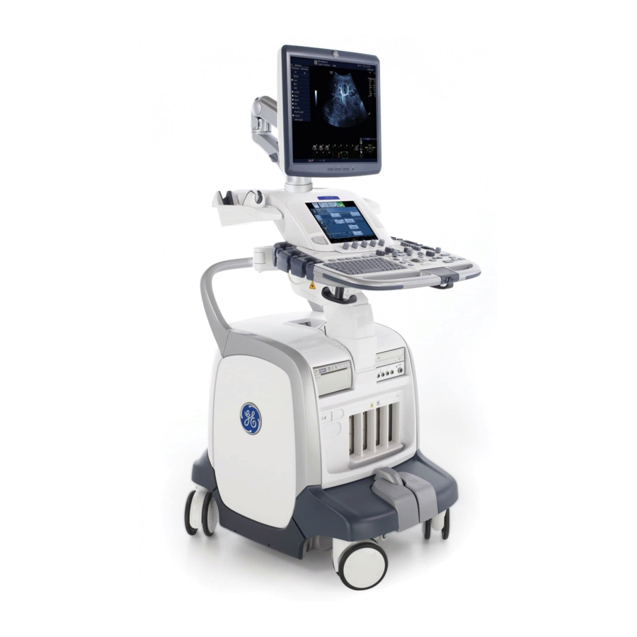
LOGIQ E9 description 5-2-1 Purpose of this section The purpose of this section is to give you an overview of LOGIQ E9 and how it functions. 5-2-2 Introduction The LOGIQ E9 ultrasound system is a high performance digital ultrasound imaging system with total data management. - Page 202 5-2-3 LOGIQ E9 general description LOGIQ E9 is a digital beamforming system. Signal flow travels from the Probe Connector Panel to the Front End Electronics, then to the Back End Processor, and finally, the results are displayed on the monitor System configuration is stored on the hard drive, inside the Back End Processor (BEP), and all necessary software is loaded from the hard drive on power up.
- Page 203 ANUAL 5-2-4 LOGIQ E9 Overall block diagram - R3.x and earlier (cont’d) CW is supported for R2.x.x or later. The CW circuitry is found on the CW version of the GRX128 board. Figure 5-1 LOGIQ E9 Block diagram - GFI configuration (BEP5.x)
- Page 204 5535208-100, R LOGIQ E9 S IRECTION ERVICE ANUAL 5-2-4 LOGIQ E9 Overall block diagram - R3.x and earlier (cont’d) Overall block diagram includes the following sections: • Main Power Supply • Front End Card Rack, with: GRLY(1) - Global Relay Board MRX (1) - Receiver Board with and without CW GTX (3) - Transmitter Boards (64 channels each, in this configuration).
- Page 205 CW is supported for R3.x.x and later. The CW circuitry is found on the MRX Board. NOTE: Figure 5-6 "LOGIQ E9 Signal Flow - MRX" on page 5-11 is identified in color to simplify the differences between R2.x.x and earlier (or GFI configuration) and R3.x.x and later (MRX). Red represents GFI configuration and blue represents MRX.
- Page 206 5535208-100, R LOGIQ E9 S IRECTION ERVICE ANUAL 5-2-5 LOGIQ E9 Overall block diagram - BEP6.x - R4.x Figure 5-3 LOGIQ E9 Block diagram - BEP6.x - FROG LOCK BRAKES MOTOR INNER OUTER LEFT BRAKE LEFT BRAKE MAIN LCD DISPLAY...
- Page 207 5535208-100, R LOGIQ E9 S IRECTION ERVICE ANUAL 5-2-6 LOGIQ E9 Overall block diagram - BEP6.x - R5.x and later Figure 5-4 LOGIQ E9 Block diagram - BEP6.x - R5.x and later FROG LOCK BRAKES MOTOR INNER OUTER LEFT BRAKE...
- Page 208 5535208-100, R LOGIQ E9 S IRECTION ERVICE ANUAL 5-2-7 Signal flow overview - GFI Configuration Figure 5-5 LOGIQ E9 Signal Flow GTX 64 Ch DRX 64 Frontplane GTX 64 Ch DRX 64 GRX 64 David Nathan GRLY GRX 128 Pulser...
- Page 209 5535208-100, R LOGIQ E9 S IRECTION ERVICE ANUAL 5-2-7 Signal flow overview (cont’d) - MRX Figure 5-6 LOGIQ E9 Signal Flow Frontplane GTX 64 Ch GTX 64 Ch David Pulser 64 Ch Option David David Converters I / Q David...
- Page 210 Harmonic Imaging Tissue Harmonic Imaging, acoustic aberrations due to tissue, are minimized by receiving and processing the second harmonic signal that is generated within the insonified tissue. LOGIQ E9`s high performance Harmonic Imaging provides superb detail resolution and penetration, outstanding contrast resolution, excellent acoustic clutter rejection and an easy to operate user interface for switching into Harmonic Imaging mode.
- Page 211 5-2-8-6 Other Modes 4D: The LOGIQ E9 Ultrasound System may be used to acquire multiple, sequential 2D (B-Mode) (B- Mode) images which can be combined to reconstruct a three dimensional image. These 4D images are useful in visualizing three-dimensional structures, and in understanding the spatial or temporal relationships between the images in the 2D (B-Mode) (B-Mode) sequence.
- Page 212 Another example method is to rotate the cross section about a line contained in the cross section. The LOGIQ E9 Ultrasound System uses the automated so called C-Scan for the motion perpendicular to automated B-scan. Once a representative...
- Page 213 5535208-100, R LOGIQ E9 S IRECTION ERVICE ANUAL 5-2-8-9 Elastography Elastography shows the spatial distribution of tissue elasticity properties in a region of interest by estimating the strain before and after tissue distortion caused by external or internal forces. The strain estimation is filtered and scaled to provide a smooth presentation when displayed.
-
Page 214: Top Console With Lcd Monitor And Operator Panel
Top Console with LCD monitor and Operator Panel 5-3-1 Purpose of this section The purpose of this section is to give you an overview of LOGIQ E9’s Top Console and to tell you how it function. 5-3-2 Transporting LOGIQ E9 The Top Console must be locked into the lower, center (X/Y) position before transporting the LOGIQ E9. - Page 215 Top Console’s location in the LOGIQ E9 The Top Console is located on the top of the LOGIQ E9, and includes the Main LCD monitor, the Monitor Arm, the Operator Panel with the Touch Screen, Speakers, an alphanumeric keyboard, and frogleg controls.
- Page 216 5535208-100, R LOGIQ E9 S IRECTION ERVICE ANUAL 5-3-4 Operator Panel 5-3-4-1 Operator Panel general description The Operator Panel includes an On/Off switch, different controls for manipulating the picture quality, and controls for use in Measure & Analyze (M&A), an alphanumeric keyboard and frogleg controls.
- Page 217 5535208-100, R LOGIQ E9 S IRECTION ERVICE ANUAL 5-3-4-1 Operator Panel general description (cont’d) Customer Removable Trackball introduced for forward production in R4. A new Bezel was introduced with different dimensions around the Trackball and Trackball Keys to fit the Removable Trackball.
- Page 218 5535208-100, R LOGIQ E9 S IRECTION ERVICE ANUAL 5-3-4-2 Operator Panel Block Diagram Figure 5-10 Operator Panel Block Diagram - R4 and earlier USB Inductive or BUTTON MATRIX Optical Trackball BUTTON MATRIX KEYBRD CONTROLLER AMBER +12V ENCODERS (X12) MATRIX HI FET...
-
Page 219: Main Console
Front and Rear Casters with lock and brake mechanism The Main Console consists of a frame that acts as the skeleton of the LOGIQ E9. The other parts, listed above, are mounted to the frame. The outside of the Main Console is covered with plastic covers. -
Page 220: Air Flow Control
Location in the LOGIQ E9 There are two filters. One located on the rear of the LOGIQ E9 and one located beneath the air cooling fans at the bottom of the LOGIQ E9. Refer to Chapter 8 for more information. -
Page 221: Power Distribution
ANUAL Section 5-7 Power distribution 5-7-1 Purpose of this section The power distribution within the LOGIQ E9 is described in this section. 5-7-2 Main Power Supply 5-7-2-1 General description The Main Power Supply’s main task is to galvanically isolate the scanner from the on-site Mains Power System and to supply the various internal subsystems with AC or DC power. - Page 222 • Back End Processor An inrush current limiter reduce the peak input current when the LOGIQ E9 is switched on. An EMI filter helps to reduce EMI to acceptable levels. The mains cord has plugs in both ends. A female plug connects to the scanner and a male plug to the wall outlet.
- Page 223 • Back End Processor An inrush current limiter reduce the peak input current when the LOGIQ E9 is switched on. An EMI filter helps to reduce EMI to acceptable levels. The mains cord has plugs in both ends. A female plug connects to the scanner and a male plug to the wall outlet.
- Page 224 5535208-100, R LOGIQ E9 S IRECTION ERVICE ANUAL 5-7-2-1 General description (cont’d) Figure 5-15 Main Power Supply MAIN POWER SUPPLY 5-7-2-2 Temperature Control The Main Power Supply is equipped with an internal fan with variable speed for temperature control. Both the temperature of the air entering the power supply and leaving the power supply are measured.
- Page 225 5535208-100, R LOGIQ E9 S IRECTION ERVICE ANUAL 5-7-3 Power Up Sequence Description 5-7-3-1 Overview The Power Up Sequence can be divided in the following steps: 1.) Switch AC Breaker to ON position 2.) Press the ON button on the Operator Panel 3.) BEP power-up...
- Page 226 IRECTION ERVICE ANUAL 5-7-4 Power Down Sequence description 5-7-4-1 Overview There are three possible scenarios for Power Down of the LOGIQ E9: • Power Down - normal power down (short push) • Enforcement Power Down (long push) • Power Loss Each of the scenarios are described below.
- Page 227 5535208-100, R LOGIQ E9 S IRECTION ERVICE ANUAL 5-7-5 Shear Wave (SWAVE) Option What is Shear Wave? A Shear wave is a transverse wave that occurs in an elastic medium when it is subjected to periodic shear. Figure 5-19 SWAVE Visually Explained A = Ultrasound “push“...
- Page 228 5535208-100, R LOGIQ E9 S IRECTION ERVICE ANUAL 5-7-5 Shear Wave (SWAVE) Option (cont’d) SWAVE Acquisition Pressing the “Start" set key initiates SWAVE acquisition. Post-SWAVE Acquisition • System displays the acquired SWAVE image and background B-mode image. • User can cycle through the acquired frames, measure and annotate.
- Page 229 5535208-100, R LOGIQ E9 S IRECTION ERVICE ANUAL 5-7-6 V Nav Inside Option The VNAV inside allows the use of probes that have built in VNAV sensors, avoiding having external cables and VNAV bracket use. The following hardware is introduced to support the VNAV option: •...
- Page 230 5535208-100, R LOGIQ E9 S IRECTION ERVICE ANUAL 5-7-6 V Nav Inside Option (cont’d) Figure 5-21 V Nav Inside Option HDMI Auxiliary Sensor Input from GRLY Figure 5-22 V Nav Inside Option Cable from GRLY to Auxiliary Sensor Input 5 - 32...
-
Page 231: Power Loss Description
LOGIQ E9 S IRECTION ERVICE ANUAL Section 5-8 Power Loss description Section 5-9 Cables for LOGIQ E9 Please refer to: • Section 9-16 "Mains Power Cables" on page 9-84 • Section 9-17 "Internal Cables" on page 9-86 Section 5-10 Probes description See: Section 9-18 "Probes"... -
Page 232: Product Manuals
ERVICE ANUAL Section 5-11 Product manuals The information needed to use and service the LOGIQ E9 scanner is collected in the documents described in this section. NOTE: Dates on screenshots are represented in MM/DD/YYYY format throughout the manual. Information on how to change the LOGIQ E9’s date can be found in Customizing Your System, Chapter 16 in the LOGIQ E9 User Manual/User Guide. -
Page 233: Service Adjustments
5535208-100, R LOGIQ E9 S IRECTION ERVICE ANUAL Chapter 6 Service Adjustments Section 6-1 Overview 6-1-1 Purpose of this chapter This section describes how to adjust the scanner. Section 6-2 LCD Monitor adjustments 6-2-1 Purpose of this section This section describes how to adjust the LCD monitor for optimal performance. - Page 234 Table 6-2 "Advanced LCD Adjustments" on page 6-4 feature descriptions For complete information, refer to the of the LOGIQ E9 Basic User Manual, Chapter 16 for R3.x.x. To obtain different test patterns for B/W or color adjustments, press Utility in the Touch Panel and select Test Patterns.
- Page 235 6-2-3-2 Contrast Use the recommended LCD settings. The contrast is adjusted by the LOGIQ E9 software, when selecting scanning modes and doing scanning adjustments. Changing the monitor’s contrast settings in one mode will influence the picture quality in other modes.
-
Page 236: Lcd Monitor Adjustments
5535208-100, R LOGIQ E9 S IRECTION ERVICE ANUAL 6-2-4 Advanced LCD Adjustments Table 6-2 Advanced LCD Adjustments Steps Corresponding Graphic NOTE: DO NOT adjust these LCD Adjustment Buttons settings unless necessary! To get access to the advanced adjustments, press the mode button for more than 10 seconds. - Page 237 5535208-100, R LOGIQ E9 S IRECTION ERVICE ANUAL 6-2-4 Advanced LCD Adjustments (cont’d) Use the right button to select any of the menu items. The details for the original LCD monitor are described below: • The Screen sub-menu: Not used on this LCD screen.
- Page 238 5535208-100, R LOGIQ E9 S IRECTION ERVICE ANUAL 6-2-4 Advanced LCD Adjustments (cont’d) Use the right button to select any of the menu items. The details are described below: • The Screen sub-menu: Not used on this LCD screen. •...
- Page 239 5535208-100, R LOGIQ E9 S IRECTION ERVICE ANUAL 6-2-5 LCD Arm and LCD Monitor range of motion Adjustment - R3.x and earlier Table 6-3 LCD Arm and LCD Monitor range of motion Adjustment - R3.x and earlier Steps Corresponding Graphic LCD in vertical position Remove the Monitor Rear Cover.
-
Page 240: Dc Offset Calibration
1.) Disconnect all connected probes. 2.) Power on the LOGIQ E9. 3.) On the Touch Panel, select Utility -> Service to access CSD. 4.) Log in as GE Service, enter current password 5.) Select Diagnostics tab. 6.) Select Service -> Diagnostics. -
Page 241: Operator Panel Movement
ERVICE ANUAL Section 6-4 Operator Panel movement 6-4-1 Purpose of this section The Operator Panel movement within the LOGIQ E9 is described in this section. 6-4-2 Adjusting the XY Locking Mechanism Table 6-4 Adjusting the XY Locking Mechanism Steps Corresponding Graphic... - Page 242 5535208-100, R LOGIQ E9 S IRECTION ERVICE ANUAL 6-4-3 Adjusting the Z Mechanism Table 6-5 Adjusting the Z Mechanism Steps Corresponding Graphic There are no adjustments for the OP Z Mechanism Manual adjustment lever vertical movement. The Z mechanism can be manually repositioned in the event the drive gear is disconnected or has failed.
- Page 243 5535208-100, R LOGIQ E9 S IRECTION ERVICE ANUAL 6-4-4-2 XY Manual Release for Lock and Brake Mechanism Table 6-7 XY Manual Release for Lock and Brake Mechanism Steps Corresponding Graphic This procedure is intended to release and XY Manual Release for Lock and adjust the XY mechanism.
- Page 244 5535208-100, R LOGIQ E9 S IRECTION ERVICE ANUAL 6-4-4-3 XY Lock Adjustment for Lock and Brake Mechanism Follow this procedure if the park lock is not working, or the lock does not respond when pressing the Frogleg Controls: Table 6-8...
- Page 245 5535208-100, R LOGIQ E9 S IRECTION ERVICE ANUAL Table 6-8 XY Manual Release for Lock and Brake Mechanism Steps Corresponding Graphic If park lock nut, (2) and park lock lever (3) Park Lock WILL NOT engage are in these positions., the lock will not when in these positions engage.
- Page 246 5535208-100, R LOGIQ E9 S IRECTION ERVICE ANUAL Table 6-8 XY Manual Release for Lock and Brake Mechanism Steps Corresponding Graphic Rotate the threaded lead screw on the Park Lock WILL NOT engage actuator, (4) counterclockwise until the lock when in these positions...
- Page 247 5535208-100, R LOGIQ E9 S IRECTION ERVICE ANUAL 6-4-5 Using the Park Lock Properly It is important to inform a customer of the following if they are experiencing problems with the XY park lock function. Be sure to: • Apply the brakes. The locking mechanism will not engage if the device can move when trying to park the console.
-
Page 248: Direction Lock And Brake Adjustments
5535208-100, R LOGIQ E9 S IRECTION ERVICE ANUAL Section 6-5 Direction Lock and Brake adjustments There are no adjustments for the Direction Lock or the brakes. Section 6-6 Adjust time-out for DICOM servers When portable (off-line), use minimum time-out and no retries or it will affect shutdown speed. - Page 249 WARNING SURFACES MAY BE WARM ENOUGH TO POSE A POTENTIAL HEAT HAZARD IF TOUCHED, EVEN WHILE IN SHUT DOWN MODE. IF A LOGIQ E9 IS ENERGIZED, AND THE FRONT PROCESSOR (CARD CAGE) COVER WARNING WARNING IS REMOVED, THE VOLTAGE TEST POINTS POSE A POTENTIAL SHOCK HAZARD.
- Page 250 The following information is necessary to properly analyze data or images being reported as a malfunction or being returned to the manufacturer: NOTE: This information is normally collected with the Alt+D or Gather Logs utility. Product Name = LOGIQ E9 From the Utility -> System -> About screen: Applications Software Software Version...
- Page 251 5535208-100, R LOGIQ E9 S IRECTION ERVICE ANUAL 7-3-3 Collecting a Screen Capture with Logs If the system malfunctions, press the Alt+D keys simultaneously. This Alt+D function is available at all times, and collects a screen capture of the image monitor, user-defined presets, and the following logs: •...
- Page 252 5535208-100, R LOGIQ E9 S IRECTION ERVICE ANUAL 7-3-3 Collecting a Screen Capture with Logs (cont’d) NOTE: For Application SW R3.x.x or later, the Service Directory is no longer located under the export folder, it is located in d:\ root directory (d:\service).
- Page 253 5535208-100, R LOGIQ E9 S IRECTION ERVICE ANUAL 7-3-4 Capturing Service Logs with ALT+D The following is a list of the Service logs captured during an ALT+D log capture: Figure 7-3 Capture Service Example Chapter 7 Diagnostics/Troubleshooting 7 - 5...
- Page 254 5535208-100, R LOGIQ E9 S IRECTION ERVICE ANUAL 7-3-5 Capturing Network Logs with Network Sniffer (Software R1.x.x) A sniffer monitors network traffic and allows you to capture network data without redirecting or altering it. Launch the network sniffer application one of the following two ways: 1.) On the Regular Scan Screen, press Alt+N.
- Page 255 5535208-100, R LOGIQ E9 S IRECTION ERVICE ANUAL 7-3-5 Capturing Network Logs with Network Sniffer (Software R1.x.x) (cont’d) NOTE: Steps describe how to filter the data so that you only record this system’s network activity. If you prefer, you may skip the filter section and start the data capture now. If you do, you will capture all network activity, not just this system’s.
- Page 256 5535208-100, R LOGIQ E9 S IRECTION ERVICE ANUAL 7-3-5 Capturing Network Logs with Network Sniffer (Software R1.x.x) (cont’d) 7.) On the Select Filter Task screen, select “Show only IP packets FROM/TO one or more IP addresses”, then select Next. The Enter Filter Settings screen opens.
- Page 257 5535208-100, R LOGIQ E9 S IRECTION ERVICE ANUAL 7-3-5 Capturing Network Logs with Network Sniffer (Software R1.x.x) (cont’d) 10.)In the Filter to Apply field, select “My Computer”. Figure 7-8 Capture Tab on Configuration Screen 11.)Select Close. The Configuration screen closes.
- Page 258 5535208-100, R LOGIQ E9 S IRECTION ERVICE ANUAL 7-3-5 Capturing Network Logs with Network Sniffer (Software R1.x.x) (cont’d) 15.)When the transaction finishes (or fails), select Ctrl+Alt+Del to open Task Manager. Select Exit to close the application and return to Windows. Then open Windows Task Manager to open the Distinct Network Monitor screen.
- Page 259 5535208-100, R LOGIQ E9 S IRECTION ERVICE ANUAL 7-3-5 Capturing Network Logs with Network Sniffer (Software R1.x.x) (cont’d) 17.)On the Distinct Network Monitor screen (Figure 7-4 "Distinct Network Monitor Window" on page 7- 6), select Capture > Stop. After stopping the data collection, a screen similar to Figure 7-11 "Save As Capture File dialog box"...
- Page 260 5535208-100, R LOGIQ E9 S IRECTION ERVICE ANUAL 7-3-6 Capturing Network Logs with Network Sniffer (Software R2.x.x or later) Wireshark is a new network sniffer program that replaces Distinct in R2.x.x or later. Functionality is similar from previous software. Logs collected should be stored under d:/log/Sniffer folder to ensure they form part of general log collection Alt+D or Collect Log.
- Page 261 5535208-100, R LOGIQ E9 S IRECTION ERVICE ANUAL 7-3-6 Capturing Network Logs with Network Sniffer (Software R2.x.x or later) (cont’d) Use filters to limit the captured data. Filter by IP or by IP and port number. By IP only: press on Capture Filter.
- Page 262 5535208-100, R LOGIQ E9 S IRECTION ERVICE ANUAL 7-3-6 Capturing Network Logs with Network Sniffer (Software R2.x.x or later) (cont’d) By IP and port: Select Capture filter. 5.) Select New. 6.) Edit name for example DICOM port 104. 7.) Enter the string with the following syntax: port xxx and host yy.yy.yy.yy, where xxx is the port number of “My Computer”...
- Page 263 5535208-100, R LOGIQ E9 S IRECTION ERVICE ANUAL 7-3-6 Capturing Network Logs with Network Sniffer (Software R2.x.x or later) (cont’d) 11.)Press Alt+N to restore Sniffer window and observe the network activity. Figure 7-16 Sniffer Window and Network Activity A.) "Packet List" pane - the packet list pane displays all the packets in the current capture file. Each line in the packet list corresponds to one packet in the capture file.
- Page 264 5535208-100, R LOGIQ E9 S IRECTION ERVICE ANUAL 7-3-6 Capturing Network Logs with Network Sniffer (Software R2.x.x or later) (cont’d) In addition to the pre capture filter, use the Filter tool on the screen to filter what is displayed. Filter the DICOM packets, since they are the most probable for the troubleshooting.
- Page 265 5535208-100, R LOGIQ E9 S IRECTION ERVICE ANUAL 7-3-6 Capturing Network Logs with Network Sniffer (Software R2.x.x or later) (cont’d) 15.)Select Displayed. This will save only the filtered values rather than the entire capture. 16.)Select SAVE. If you perform Alt+D or Gather Logs, these sniffer logs will be included in the zip file.
- Page 266 5535208-100, R LOGIQ E9 S IRECTION ERVICE ANUAL Section 7-4 Screen Captures 7-4-1 Purpose of this Section To capture screen images that can be used for diagnostic and troubleshooting purposes. 7-4-2 Ctrl+PrintScreen Shortcut A Ctrl+PrintScreen shortcut is available for quickly capturing the image displayed on the system. Images captured using this shortcut are saved in the d:\export\service\image (R2.x.x or earlier) or in...
- Page 267 5535208-100, R LOGIQ E9 S IRECTION ERVICE ANUAL Section 7-5 Common Service Desktop 7-5-1 Purpose of this Section This section describes the features of the Common Service Desktop (CSD). NOTE: To run diagnostics, you should detach all probes. NOTE: Reboot the system after performing any diagnostics before returning the system to customer use.
- Page 268 5535208-100, R LOGIQ E9 S IRECTION ERVICE ANUAL 7-5-2 Error Logs 1.) From the Log Viewer page click the Click Here link. Figure 7-21 Error Logs - Log Viewer 2.) Select the log you wish to view. Figure 7-22 Log Viewer - Log Options NOTE: Informatics is no longer present for R4.x and later.
- Page 269 5535208-100, R LOGIQ E9 S IRECTION ERVICE ANUAL 7-5-2 Error Logs (cont’d) Features of the log viewer include: • Plot logs and pages using the Utilities menu. • Text search using the Search menu. • Color-coded log entries to identify severity levels: Green: A Level 3 severity indicates that the parameter is within 0% - 50% of specified tolerance.
- Page 270 5535208-100, R LOGIQ E9 S IRECTION ERVICE ANUAL 7-5-3 Diagnostics Window Overview 1.) Instructions Frame Displays either test-specific text or the default instructions. 2.) Status Frame Initially displays the last known status for a selected diagnostic. Once the diagnostic starts, the frame displays the “current”...
- Page 271 5535208-100, R LOGIQ E9 S IRECTION ERVICE ANUAL 7-5-3 Diagnostics Window Overview (cont’d) Figure 7-24 Diagnostic Window Overview The Service Diagnostics windows have some advanced features. NOTE: The Loop Count field must have a value of 2 or greater to activate the Advanced features.
- Page 272 5535208-100, R LOGIQ E9 S IRECTION ERVICE ANUAL 7-5-3 Diagnostics Window Overview (cont’d) 11.)Select the Loop Order: ABCABCABC = Runs the selected diagnostics as one group and runs each group for the number of loops specified. AAABBBCCC = Runs the selected diagnostics one at a time for the maximum loop value then proceeds to the next diagnostic.
- Page 273 5535208-100, R LOGIQ E9 S IRECTION ERVICE ANUAL 7-5-3 Diagnostics Window Overview (cont’d) Figure 7-27 Details Window Figure 7-28 Details Table Chapter 7 Diagnostics/Troubleshooting 7 - 25...
- Page 274 5535208-100, R LOGIQ E9 S IRECTION ERVICE ANUAL 7-5-4 Diagnostic Utility Freezes Up/Times Out If the diagnostic utility has timed out (freezes up, will no longer run) you have to close the Common Service Desktop and launch it again. This may occur when issues with the scanner cause the diagnostic utility to fail completion of an executed test.
- Page 275 LOGIQ E9 S IRECTION ERVICE ANUAL 7-5-6 OP Panel Utilities - Op Panel Interface The Operator Panel functionality can be tested using a program (GE Test App) available through the Service Platform. R4 or earlier Chapter 7 Diagnostics/Troubleshooting 7 - 27...
- Page 276 The other buttons on the Startup tab will now be active. See: Figure 7-30 Figure 7- 31 "Attach and GE Test App Startup Tab - Detach and Other Buttons Active - R4 and earlier" on page 7-30. 7 - 28...
- Page 277 5535208-100, R LOGIQ E9 S IRECTION ERVICE ANUAL 7-5-6-1 Launching the Op Panel Test (cont’d) Figure 7-30 Attach and GE Test App Startup Tab - Attach Button Active - R4 and earlier Chapter 7 Diagnostics/Troubleshooting 7 - 29...
- Page 278 ERVICE ANUAL 7-5-6-1 Launching the Op Panel Test (cont’d) Figure 7-31 Attach and GE Test App Startup Tab - - R4 and earlier Detach and Other Buttons Active 16.)Select the tabs to test the various features of the Op Panel.
- Page 279 5535208-100, R LOGIQ E9 S IRECTION ERVICE ANUAL 7-5-6-1 Launching the Op Panel Test (cont’d) Figure 7-32 OP Panel Test Start Up - R5 and later For R5 and later, the upper right corner indicates the type of Op Panel is detected (connected).
- Page 280 5535208-100, R LOGIQ E9 S IRECTION ERVICE ANUAL 7-5-6-2 Trackball Tab Test the trackball functionality by moving the pointer over the blue box. Verify that the X and Y position are updated as the pointer is moved. Test the Left and Right select buttons by pressing each button on the op panel. Verify that the corresponding button is highlighted when each button is pressed.
- Page 281 5535208-100, R LOGIQ E9 S IRECTION ERVICE ANUAL 7-5-6-3 Keyboard Tab Test the keyboard functionality by typing on the keyboard. Verify that the corresponding key is highlighted when each key is pressed. See: Figure 7-35 Figure 7-36. NOTE: The keyboard test does not give an indication when the Print Screen button is pressed.
- Page 282 5535208-100, R LOGIQ E9 S IRECTION ERVICE ANUAL 7-5-6-4 Slidepots Tab Test the slidepot (TGC) functionality by moving each slidepot through its range. Verify that the visual and numeric position of the slide pot are updated as the slide pot is moved.
- Page 283 5535208-100, R LOGIQ E9 S IRECTION ERVICE ANUAL 7-5-6-5 Encoders Tab Test the encoder functionality by rotating each encoder knob. Verify that the position is updated as the encoder is moved. Test the encoder button selection function by pressing each knob on the op panel. Verify that the corresponding knob is highlighted when each knob is pressed.
- Page 284 5535208-100, R LOGIQ E9 S IRECTION ERVICE ANUAL 7-5-6-6 Pushbuttons Tab Test the pushbutton functionality by pressing each button on the operator panel. Verify that the corresponding pushbutton is highlighted when each button is pressed. See: Figure 7-41 Figure 7-42.
- Page 285 IRECTION ERVICE ANUAL 7-5-6-7 LEDs Tab Test the LED functionality by selecting each button or knob on the GE Test App. Verify that the corresponding LED is illuminated when each button or knob is selected. See: Figure 7-43 Figure 7-44.
- Page 286 5535208-100, R LOGIQ E9 S IRECTION ERVICE ANUAL 7-5-6-8 Touch Screen Tab Test the Touch Screen functionality by pressing on the Touch Screen of the upper operator panel. Verify that the press is indicated in the black window by a highlighted circle. See:...
- Page 287 7-5-7-1 Disruptive Mode The customer enables this feature by choosing “Disruptive Mode” and confirming “Yes”, before a GE Service FE can access the customer’s ultrasound scanner remotely. “Disruptive Mode” can be requested remotely by the service technician or OLC, or it can be selected by the customer directly on the scanner or workstation.
- Page 288 LOGIQ E9 S IRECTION ERVICE ANUAL 7-5-8 Diagnostics for Service Diagnostics 7-9-19 "LOGIQ E9 Transmit and Receive Signal Path Diagnostics" on page 7-268. Also for 7-5-12-15 "Diagnostics Window Overview - R3.x.x and later" on page 7-96 7-5-8-1 Digital Receive See: 7-5-3 "Diagnostics Window Overview"...
- Page 289 The intermittent errors encountered by the diagnostic may not be due to real failure; therefore the DRX High Speed Bit Error Rate Diagnostic test results are not reliable when under this configuration. This problem does not affect in any way the operation or performance of the LOGIQ E9, it is only related to the diagnostic result.
- Page 290 5535208-100, R LOGIQ E9 S IRECTION ERVICE ANUAL 7-5-8-1 Digital Receive (cont’d) Name: DRX Signal Path Test (this test provides the most coverage on the DRX) Description: Digital signal path sourced from input to Nathan. Does not test ADC. Sends simulated data across the signal path.
- Page 291 5535208-100, R LOGIQ E9 S IRECTION ERVICE ANUAL 7-5-8-1 Digital Receive (cont’d) Name: Nathan MLA Data Alignment Test Description: Output TVG of Nathan with system configured for max number of MLAs supported by system. Each MLA gain is set differently to detect MLA ordering problems. Verifies the alignment (16 identical samples in a row) of IF to GFI.
- Page 292 5535208-100, R LOGIQ E9 S IRECTION ERVICE ANUAL 7-5-8-2 Memory (cont’d) Assesses the general state of the system. Tests the integrity of memory and communication of the described boards. Tests all of the on-board memory, including registers. The utility fills the memory with data, retrieves the data, and compares it to the original data.
- Page 293 5535208-100, R LOGIQ E9 S IRECTION ERVICE ANUAL 7-5-8-2 Memory (cont’d) Name: GTX IF FPGA Memory Test Description: Tests memory of Interface FPGAs on the GTX boards NOTE: Also run the GTX Memory Test (next test below) for a full range of testing capacity.
- Page 294 5535208-100, R LOGIQ E9 S IRECTION ERVICE ANUAL 7-5-8-3 See: 7-5-3 "Diagnostics Window Overview" on page 7-22 for a description of the looping and list features. Symptoms: • TGC Problems • Doppler Audio Problems • Image Artifacts • Intermittent Instability 1.) Select the GFI checkbox to run all the tests, or select the individual subtests to run only the selected...
- Page 295 5535208-100, R LOGIQ E9 S IRECTION ERVICE ANUAL 7-5-8-3 GFI (cont’d) Name: GFI Swept Demodulator Test Description: Performs a signal path test of the swept demodulator FPGA on the GFI Run Time: 00:05 If this test failed: 1.) Replace the GFI board.
- Page 296 5535208-100, R LOGIQ E9 S IRECTION ERVICE ANUAL 7-5-8-3 GFI (cont’d) Name: GFE Access Test Description: Reads the version of the GFE FPGA Run Time: 00:01 If this test failed: 1.) Replace the GFI board. Name: Relay LVDS Test Description: Tests the LVDS connection between the GFI interface and the GRLY...
- Page 297 5535208-100, R LOGIQ E9 S IRECTION ERVICE ANUAL 7-5-8-4 System See: 7-5-3 "Diagnostics Window Overview" on page 7-22 for a description of the looping and list features. Symptoms: • High temperature reports on the Home page. • Temperature specifications are out of tolerance.
- Page 298 5535208-100, R LOGIQ E9 S IRECTION ERVICE ANUAL 7-5-8-4 System (cont’d) NOTE: You can also view temperature logs in the System Health Information section of the Home page. These logs may help identify a trend or subsystem where temperature and voltage have been high.
- Page 299 5535208-100, R LOGIQ E9 S IRECTION ERVICE ANUAL 7-5-8-5 Noise See: 7-5-3 "Diagnostics Window Overview" on page 7-22 for a description of the looping and list features. Symptoms: • Image artifacts • Image noise • Poor image quality • Missing image channels 1.) Select the Noise checkbox or the individual subtest to run the test.
- Page 300 5535208-100, R LOGIQ E9 S IRECTION ERVICE ANUAL 7-5-8-5 Noise (cont’d) Name: Noise Floor Test Description: Measures the noise floor of the System. The entire system is required for this diagnostic. The noise floor is calculated from IQ data received without a signal source.
- Page 301 5535208-100, R LOGIQ E9 S IRECTION ERVICE ANUAL 7-5-8-7 Transmit/Receive Name: T/R Channel Test Description: Transmit and Receive Channel Test. Transmits on one at a time and received on one channel at a time using an open probe connector. Run Time: 00:03 If this test failed: 1.) Swap front-plane boards to determine if the failure point changes as the boards are moved.
- Page 302 5535208-100, R LOGIQ E9 S IRECTION ERVICE ANUAL 7-5-8-8 Analog Receive See: 7-5-3 "Diagnostics Window Overview" on page 7-22 for a description of the looping and list features. Symptoms: • Image artifacts - channel failure/noise 1.) Select the Analog Receive checkbox to run all the tests, or select the individual subtests to run only the selected tests.
- Page 303 5535208-100, R LOGIQ E9 S IRECTION ERVICE ANUAL 7-5-8-8 Analog Receive (cont’d) Tests the signal path from the GFI to the backplane (GTX) to the GRX. Name: DC Offset Calibration Utility NOTE: The DC Offset Calibration Utility diagnostic MUST be run when the DRX boards are replaced or moved.
- Page 304 5535208-100, R LOGIQ E9 S IRECTION ERVICE ANUAL 7-5-8-8 Analog Receive (cont’d) Name: Analog RX Test (Low Gain) Description: Signal path test of the GRX boards with a TGC set to low gain. Run Time: 00:02 If this test failed: 1.) Swap DRX boards to determine if the failure point changes as the boards are moved.
- Page 305 5535208-100, R LOGIQ E9 S IRECTION ERVICE ANUAL 7-5-8-9 Analog CW Analog Continuous Wave (CW) Doppler Tests. Under Service Diagnostics / Analog CW. INPUT > a sine wave generated on the GFI test vector generator and injected on the GRX board(-s).
- Page 306 5535208-100, R LOGIQ E9 S IRECTION ERVICE ANUAL 7-5-8-9 Analog CW (cont’d) The 3-term Blackman-Harris window function is used for the analog CW tests. The input frequency is 2.521 MHz for a number of the tests and with the Mixer clock at 2.5 MHz; a Doppler frequency at 21 kHz should result.
- Page 307 5535208-100, R LOGIQ E9 S IRECTION ERVICE ANUAL 7-5-8-9 Analog CW (cont’d) Name: Service Diagnostics / Analog CW / GRX aCW IQ Symmetry For each subtest, a signal is setup with f0=2.521 MHz, the BP filter at 3.1 MHz and a mixer frequency of 2.5 MHz.
- Page 308 5535208-100, R LOGIQ E9 S IRECTION ERVICE ANUAL 7-5-8-9 Analog CW (cont’d) Name: Service Diagnostics / Analog CW / GRX aCW Post Mixer Gain For each subtest, a signal is set up with f0=2.521 MHz, the BP filter at 3.1 MHz and a mixer frequency of 2.5 MHz.
- Page 309 5535208-100, R LOGIQ E9 S IRECTION ERVICE ANUAL 7-5-8-9 Analog CW (cont’d) Name: Service Diagnostics / Analog CW / GRX aCW Dither Injection A signal is injected in the dither input and result in the received I/Q data is checked. The test signal generator is used for signal injection where the input signal is f0=2.521 MHz, the BP filter at 3.1 MHz...
- Page 310 5535208-100, R LOGIQ E9 S IRECTION ERVICE ANUAL 7-5-8-9 Analog CW (cont’d) Name: Service Diagnostics / Analog CW / GRX ADC Digital LVDS For the Analog-to-Digital Converter Digital Low-Voltage Differential Signaling test, the digital link from the Doppler ADC and to the GFI board is verified. To verify signal integrity, the ADC is set up to continuously transmit a predefined bit-pattern.
- Page 311 5535208-100, R LOGIQ E9 S IRECTION ERVICE ANUAL 7-5-8-10 I/O Board Tests See: 7-5-3 "Diagnostics Window Overview" on page 7-22 for a description of the looping and list features. Symptoms: • Intermittent Problems • Popup messages warning of system voltage problems - I/O Board Pwr Supply Test •...
- Page 312 5535208-100, R LOGIQ E9 S IRECTION ERVICE ANUAL 7-5-8-10 I/O Board Tests (cont’d) Name: I/O Board Pwr Supply Test NOTE: Description: Compares all local I/O Board voltages to their specified values. Run Time: 00:01 If this test failed: 1.) Replace the I/O Board.
- Page 313 5535208-100, R LOGIQ E9 S IRECTION ERVICE ANUAL 7-5-8-10 I/O Board Tests (cont’d) Name: I/O Board Loop Back Test Description: Basic test of the USB communications with the I/O Board Run Time: 00:01 If this test failed: 1.) Verify that the USB cable/connections are properly connected. If the problem continues: 2.) Swap the USB cable/device with a known working cable/device.
- Page 314 5535208-100, R LOGIQ E9 S IRECTION ERVICE ANUAL 7-5-8-10 I/O Board Tests (cont’d) NOTE: The following Video tests can be used when the Touch Panel and the keys on the control panel are on/illuminated, but the monitor does not come on.
- Page 315 5535208-100, R LOGIQ E9 S IRECTION ERVICE ANUAL 7-5-8-11 Tx Power Supply Test See: 7-5-3 "Diagnostics Window Overview" on page 7-22 for a description of the looping and list features. Symptoms: • System will not scan • Interrupted scanning •...
- Page 316 5535208-100, R LOGIQ E9 S IRECTION ERVICE ANUAL 7-5-8-11 Tx Power Supply Test (cont’d) Name: TxPs Control Test Description: Transmit Power Supply Control Test (Verifies the voltage points are within specifications) Run Time: 00:10 If this test failed: 1.) Replace the power supply...
- Page 317 5535208-100, R LOGIQ E9 S IRECTION ERVICE ANUAL 7-5-8-12 EPS (Extended Power Shutdown) or CB (ChargeBoard used in BEP6) Tests See: 7-5-3 "Diagnostics Window Overview" on page 7-22 for a description of the looping and list features. Symptoms: • System shuts down immediately after power loss/interruption 1.) Select the Extended Power Shutdown Tests checkbox to run all the tests, or select the individual...
- Page 318 5535208-100, R LOGIQ E9 S IRECTION ERVICE ANUAL 7-5-8-12 EPS (Extended Power Shutdown) or CB (ChargeBoard used in BEP6) Tests (cont’d) Name: Extended Power Shutdown Detection Test Description: Extended Power Shutdown Detection Test (Verifies the BEP can communicate with the...
- Page 319 5535208-100, R LOGIQ E9 S IRECTION ERVICE ANUAL 7-5-8-13 bayBIRD Tests See: 7-5-3 "Diagnostics Window Overview" on page 7-22 for a description of the looping and list features. Symptoms: • 3D triangulation position is off/wrong • V Nav Issues/poor tracking NOTE: RF/EMI interference may also cause conditions of these symptoms.
- Page 320 5535208-100, R LOGIQ E9 S IRECTION ERVICE ANUAL 7-5-8-13 bayBIRD Tests (cont’d) Sensor 4 added for DriveBay2+ 3D Tracking System, introduced in R4. Name: Run All Tests Description: Runs all of the tests that are in the box Run Time: 00:24 If this test failed: 1.) Run subsequent tests as identified in the failed test results...
- Page 321 5535208-100, R LOGIQ E9 S IRECTION ERVICE ANUAL 7-5-8-13 bayBIRD Tests (cont’d) Name: Transmitter Description: Runs the tests for Transmitter Run Time: 00:21 If this test failed: 1.) If the problem still persists, replace the bayBIRD. Name: System Description: Runs the tests for System Run Time: 00:25 1.) If the problem still persists, replace the bayBIRD.
- Page 322 5535208-100, R LOGIQ E9 S IRECTION ERVICE ANUAL 7-5-9 DVR Test Figure 7-48 DVR Test Screen Name: DVR Version Test Description: Reads the current version of the DVR board if installed Run Time: 00:01 1.) If fails, re-seat board and run DVR self test 2.) If problem persist, replace DVR Board...
- Page 323 5535208-100, R LOGIQ E9 S IRECTION ERVICE ANUAL 7-5-10 Diagnostics - BEP For Diagnostic differences, see 7-5-12 "Diagnostics - BEP Interactive Tests - R4.x and later" on page 7-83. 7-5-10-1 Essential Tests See: 7-5-3 "Diagnostics Window Overview" on page 7-22 for a description of this window’s features.
- Page 324 5535208-100, R LOGIQ E9 S IRECTION ERVICE ANUAL 7-5-10-3 System Board See: 7-5-3 "Diagnostics Window Overview" on page 7-22 for a description of this window’s features. Runs tests on essential functions of the PC Mother Board. The test results are displayed in the Status portion of the window.
- Page 325 5535208-100, R LOGIQ E9 S IRECTION ERVICE ANUAL 7-5-10-4 Hard Disk Drive Surface Scan See: 7-5-3 "Diagnostics Window Overview" on page 7-22 for a description of this window’s features. Runs tests on essential functions of the Hard Disk Drive. The test results are displayed in the Status portion of the window.
- Page 326 5535208-100, R LOGIQ E9 S IRECTION ERVICE ANUAL 7-5-10-5 Hard Disk Drive Quick Test See: 7-5-3 "Diagnostics Window Overview" on page 7-22 for a description of this window’s features. Runs an overview set of tests on essential functions of the Hard Disk Drive. The test results are displayed in the Status portion of the window.
- Page 327 5535208-100, R LOGIQ E9 S IRECTION ERVICE ANUAL 7-5-10-6 Video Card See: 7-5-3 "Diagnostics Window Overview" on page 7-22 for a description of this window’s features. Runs a test on essential functions of the Video Card. The test results are displayed in the Status portion of the window.
- Page 328 5535208-100, R LOGIQ E9 S IRECTION ERVICE ANUAL 7-5-10-7 Network Adapter See: 7-5-3 "Diagnostics Window Overview" on page 7-22 for a description of this window’s features. Runs a test on essential functions of the Network Interface. The test requires the system to be connected to a network.
- Page 329 5535208-100, R LOGIQ E9 S IRECTION ERVICE ANUAL 7-5-10-8 Network Adapter Diagnostic Changes for R4 Network Adapter Test is split into 2 folders: • Network Adapter - see: Table 7-124 on page 7-157 Table 7-125 on page 7-158 • Network Adapter Reliability - see:...
- Page 330 5535208-100, R LOGIQ E9 S IRECTION ERVICE ANUAL 7-5-11 Diagnostics - BEP Interactive Tests Table 7-1 BEP Interactive Test Description Table - R3.x and earlier Test Description AVI playback Tests playing back an AVI file. CD-R test Tests writing and reading to a CDR...
- Page 331 5535208-100, R LOGIQ E9 S IRECTION ERVICE ANUAL 7-5-12 Diagnostics - BEP Interactive Tests - R4.x and later Interactive tests in R4 and later have been reduced. Tests that are not supported are no longer listed. Table 7-2 BEP Interactive Test Description Table - R4.x...
- Page 332 5535208-100, R LOGIQ E9 S IRECTION ERVICE ANUAL 7-5-12-1 Keyboard See: 7-5-3 "Diagnostics Window Overview" on page 7-22 for a description of this window’s features. 1.) Click the Execute button on the Keyboard window. The PC-Doctor Keyboard Test opens. 2.) Select your keyboard type from the drop-down menu. Usually the default choice is the correct one.
- Page 333 5535208-100, R LOGIQ E9 S IRECTION ERVICE ANUAL 7-5-12-1 Keyboard (cont’d) Footswitch Tests Under Service Diagnostics / BEP Interactive/ Keyboard INPUT > Press left, middle or right footswitch keys. OUTPUT > Keys will be registered as follows: Left Footswitch = Left Windows + F10...
- Page 334 5535208-100, R LOGIQ E9 S IRECTION ERVICE ANUAL 7-5-12-3 Audio (Sound) See: 7-5-3 "Diagnostics Window Overview" on page 7-22 for a description of this window’s features. 1.) Click the Execute button at the bottom of the screen. Wait approximately 30 seconds for the first test screen to open.
- Page 335 5535208-100, R LOGIQ E9 S IRECTION ERVICE ANUAL 7-5-13 Touch Panel 7-5-13-1 Calibration NOTE: Always try TP calibration verification before attempting to calibrate. 7-5-13-2 "Calibration Verification" on page 7-87. If the Touch Panel is so far out of calibration, hangs or does not calibrate and the normal calibration procedure does not work, it may be necessary to do a complete Pre-calibration.
- Page 336 5535208-100, R LOGIQ E9 S IRECTION ERVICE ANUAL 7-5-14 4D Motor Controller NOTE: This test requires a 4D probe be connected to the system. This test requires a 4D probe to be connected to the system. Name: Presence Test Description: This test detects the presence of the 4D Motor Controller.
- Page 337 5535208-100, R LOGIQ E9 S IRECTION ERVICE ANUAL 7-5-14 4D Motor Controller (cont’d) Name: Static 3D Test Description: Performs a basic static 3D scan using the RAB2-5 probe connected in probe socket 4. Run Time: 00:11 If this test failed: 1.) Verify an RAB2-5 probe is connected to probe socket 4 (right-most probe socket).
- Page 338 5535208-100, R LOGIQ E9 S IRECTION ERVICE ANUAL 7-5-15 Patient I/O Tests Under Service Diagnostics / Patient I/O. This procedure provides a basic test of the ability of the system to start and stop the acquisition of data from the Patient I/O Module to the Host via the GFI.
- Page 339 5535208-100, R LOGIQ E9 S IRECTION ERVICE ANUAL 7-5-16 Configuration 7-5-16-1 Software Options Interface Use this window to add, delete, and view details for software options. • Add = Click the Add button to enter a new Software Option Key.
- Page 340 5535208-100, R LOGIQ E9 S IRECTION ERVICE ANUAL 7-5-17-2 Disruptive Mode Allows you to enable or disable disruptive mode troubleshooting. If you are accessing through InSite ExC, this can only be enabled with the customer/operator confirmation. 7-5-17-3 Disk Usage View capacity and usage statistics for the different disk drives.
- Page 341 5535208-100, R LOGIQ E9 S IRECTION ERVICE ANUAL 7-5-17-10 Disk Defragmenter Disk fragmentation can reduce the amount of disk space available, and slow computing speed. Use the disk defragmenter to restore optimum disk space and speed performance. NOTE: System performance can be significantly reduced while the Disk Defragmenter is running.
- Page 342 5535208-100, R LOGIQ E9 S IRECTION ERVICE ANUAL 7-5-17-11 Gather Logs Utility Click the Gather Logs button to prepare them for retrieval by the On Line Center. The logs are compressed into a .zip file and the filepath and file name is displayed on the window.
- Page 343 5535208-100, R LOGIQ E9 S IRECTION ERVICE ANUAL 7-5-17-14 Scanner Documentation Interface Use this to view the user and service documentation for the system. You need to have your documentation disk inserted in the drive in order to open it. Otherwise you will see the message displayed in Figure 7-50 "Scanner Documentation Interface Window"...
- Page 344 For directions on how to configure the sniffer go to "Capturing Network Logs with Network Sniffer (Software R1.x.x)" on page 7-6. LOGIQ E9 R2.x.x or later Distinct was replaced by Wireshark. This menu is no longer available. Use Alt+N to open the sniffer application. 7-5-17-16 Virtual Console Observation (VCO) VCO is used by a remote service technician or the Online Center (OLC) to access and modify all scanner settings and programs on the customer's ultrasound scanner.
- Page 345 5535208-100, R LOGIQ E9 S IRECTION ERVICE ANUAL 7-5-19 Noise Ultrasound machines are susceptible to Electromagnetic Interference (EMI) from radio frequencies, magnetic fields, and transients in the air or wiring. They also generate EMI. Possible EMI sources should be identified before the unit is installed.
- Page 346 5535208-100, R LOGIQ E9 S IRECTION ERVICE ANUAL This page was intentionally left blank. 7 - 98 Section 7-5 - Common Service Desktop...
-
Page 347: Replacement Procedures
Overview 8-1-1 Purpose of this chapter This chapter describes how to remove and install, or replace, modules and subsystems in the LOGIQ E9. It also includes instructions for installing and re-installing the software. Chapter 8 Replacement procedures 8 - 1... -
Page 348: Warnings And Important Information
This section includes important information. Read it before doing any of the procedures in this chapter. 8-2-2 Warnings Energy Control and Power Lockout for LOGIQ E9 NOTICE WHEN SERVICING PARTS OF THE SYSTEM WHERE THERE IS EXPOSURE TO VOLTAGE GREATER THAN 30 VOLTS: 1. - Page 349 5535208-100, R LOGIQ E9 S IRECTION ERVICE ANUAL 8-2-2 Warnings (cont’d) DO NOT TOUCH ANY BOARDS WITH INTEGRATED CIRCUITS PRIOR TO TAKING THE WARNING WARNING NECESSARY ESD PRECAUTIONS. 1. ALWAYS CONNECT YOURSELF, VIA AN ARM-WRIST STRAP, TO THE ADVISED ESD CONNECTION POINT LOCATED ON THE REAR OF THE SCANNER (NEAR THE POWER CONNECTOR).
- Page 350 Equipment being returned must be clean and free of blood and other infectious substances. GE Healthcare policy states that body fluids must be properly removed from any part or equipment prior to shipment. GE Healthcare employees, as well as customers, are responsible for ensuring that parts/ equipment have been properly decontaminated prior to shipment.
- Page 351 10-4-2 "“Standard” GE Tool Kit in the USA" on page 10-4, the following tools (TORX bits or drivers) are needed to service the LOGIQ E9. If the torque is not indicated with the procedure, hand tighten the screws/nuts. Table 8-1...
-
Page 352: Definitions Of Left, Rear / Back, Right And Front
5535208-100, R LOGIQ E9 S IRECTION ERVICE ANUAL Section 8-3 Definitions of Left, Rear / Back, Right and Front Figure 8-1 illustrates what is the Left Side (1), Rear / Back (2), Right Side (3), and Front (4) of the LOGIQ E9. -
Page 353: Loading / Reloading / Upgrading The Software
Section 8-4 Loading / Reloading / Upgrading the Software 8-4-1 Purpose of this section This section describes how to install and/or reinstall software on LOGIQ E9. 8-4-2 LOGIQ E9 models versus software requirement Table 8-2 LOGIQ E9 Software Configurations and Hardware/Software Compatibility -... - Page 354 As the images are moved, the database will point to the new location. If the backup procedure is not completed correctly, the images and database information could be lost. Refer to the latest revision of the LOGIQ E9 Basic User Manual, Chapter 3 to perform the following tasks: •...
- Page 355 The software is delivered on two CDs, one for the system software (which is technically a DVD) and one for the LOGIQ E9 application software. In some cases, a third CD with a software patch, may also be included. A software patch CD is used when a few new files should be installed or changed, but the changes do not require a complete software load.
- Page 356 5535208-100, R LOGIQ E9 S IRECTION ERVICE ANUAL 8-4-6-3 Overview (cont’d) NOTE: System Software may also be referred to as the Base Image or Ghost. WHILE THE SOFTWARE INSTALL PROCEDURE IS DESIGNED TO PRESERVE DATA, WARNING WARNING YOU SHOULD SAVE ANY PATIENT DATA, IMAGES, SYSTEM SETUPS AND...
- Page 357 For a C: Partition load, this step is precautionary in the event the software load has issues. The data should transfer over for a C: Partition load. See: the latest revision of the LOGIQ E9 Basic User Manual, Chapter 3. 6.) Confirm with customer that all patient data has been archived. If not, perform the archive.
- Page 358 5535208-100, R LOGIQ E9 S IRECTION ERVICE ANUAL 8-4-6-4 System Software Load - R3 and earlier (cont’d) 11.)Press any key to continue; or to abort, remove the disk from the drive and press CTRL-C. The System Software Load Instruction window displays.
- Page 359 System Software Load - R3 and earlier (cont’d) 12.)Choose one of the following: a.) Select [1] ONLY if a [2] update cannot be used: Selecting [1] performs a complete LOGIQ E9 software installation. (All data will be erased.) b.) Select [2] to update/re-install the software on the C:\ partition. (Only data on the C:\ partition will be erased.
- Page 360 5535208-100, R LOGIQ E9 S IRECTION ERVICE ANUAL 8-4-6-4 System Software Load - R3 and earlier (cont’d) 14.)Remove the Base Load disk. NOTE: If you do not remove the disk, the Base Load process repeats when the system boots up.
- Page 361 Wait until the LCDs on the Operator Panel are switched off and the ON switch has turned amber. Power ON the LOGIQ E9. Some Windows screens will be displayed before displaying the software load warning message. The scanner boots from the Software disk and displays a load warning message.
- Page 362 5535208-100, R LOGIQ E9 S IRECTION ERVICE ANUAL Table 8-4 Software Load - R4 or later Steps Corresponding Graphic Press any key to continue; or to abort, remove the disk from the drive and press System Software load CTRL-C. instruction (R.4) The System Software Load Instruction window displays.
- Page 363 DO NOT proceed with the Application Software load yet. Remove the base load disk. NOTE: If you do not remove the disk, the base load process repeats when the LOGIQ E9 boots To restart the LOGIQ E9, type "exit" and press enter to reboot.
- Page 364 5535208-100, R LOGIQ E9 S IRECTION ERVICE ANUAL Table 8-4 Software Load - R4 or later Steps Corresponding Graphic Wait until all drivers are installed Restart Windows Message automatically and the reboot is complete. DO NOT PRESS ANY KEY , ignore all messages until the automatic reboot is complete.
- Page 365 IRECTION ERVICE ANUAL 8-4-6-6 Loading the Application Software 1.) Insert the applicable disk labelled LOGIQ E9 Application SW. 2.) Wait about 30 seconds. A window opens (see: Figure 8-8) showing the contents of the drive. 3.) Double-click on LoadSoftware.bat to load the software.
- Page 366 5535208-100, R LOGIQ E9 S IRECTION ERVICE ANUAL 8-4-6-6 Loading the Application Software (cont’d) 5.) As indicated, press any key to continue, ONLY for R4 and earlier. The process is completely automated and provides you with several status messages, including the...
- Page 367 5535208-100, R LOGIQ E9 S IRECTION ERVICE ANUAL 8-4-6-6 Loading the Application Software (cont’d) 7.) Remove the applications disk from the DVD drive. 8.) From the Start Applications window, select “Start” (if the CD is still in the tray; otherwise, the system starts up automatically).
- Page 368 5535208-100, R LOGIQ E9 S IRECTION ERVICE ANUAL 8-4-6-8 Verifying the software option key settings NOTE: Software Option Dongles are software version dependant. If a new software version has been installed, follow installation instructions for that software. Usually, new software option strings are needed.
- Page 369 8-4-6-11 Restoring Patient Archive and System Configurations For complete instructions, refer to the latest revision of the LOGIQ E9 Basic User Manual, Chapter 16. 1.) From the Touch Panel, select Utility -> System -> Backup/Restore. 2.) On the Restore screen, select as needed: Patient archive to restore the patient archive images.
- Page 370 Loading the Application Software Only Use this procedure to update application software only. 1.) Place the LOGIQ E9 Application Software DVD in the CD/DVD Drive, while the system is running. 2.) Reboot the system. The Start Application window displays. Figure 8-14 Start Application window (window will reflect actual software version instead of “Rx.x.x”)
- Page 371 5535208-100, R LOGIQ E9 S IRECTION ERVICE ANUAL 8-4-7 Loading the Application Software Only (cont’d) Figure 8-15 Command Window NOTE: The window reflects the actual software version instead of “R6.0.6EP1_L9_, as shown above. 4.) As indicated, press any key to continue.
- Page 372 Loading the Application Software Only (cont’d) After the reboot, the Start Application window displays. 6.) Remove the LOGIQ E9 Applications Software DVD from the DVD drive. 7.) Store the application disks with the system. 8.) Remove and destroy the previous Application software version disks.
- Page 373 5535208-100, R LOGIQ E9 S IRECTION ERVICE ANUAL 8-4-7 Loading the Application Software Only (cont’d) Figure 8-19 Enter Option String NOTE: All systems must have at least the Basic Option string for the software to run. Any single Option String may enable multiple options (i.e., Basic).
- Page 374 5535208-100, R LOGIQ E9 S IRECTION ERVICE ANUAL 8-4-7-2 Verify and Update Vital Product Data It is essential that Vital Product Data (VPD) is verified or updated after any hardware change to the Back End Processor (BEP) or Front End Processors.
-
Page 375: Replacing Covers And Bumpers
5535208-100, R LOGIQ E9 S IRECTION ERVICE ANUAL Section 8-5 Replacing Covers and Bumpers 8-5-1 Purpose of this section This section describes how to replace the Covers and Bumpers on the LOGIQ E9. Chapter 8 Replacement procedures 8 - 29... - Page 376 Manpower / Tools Time One person / 5 minutes per Refer to: 8-2-5 "Tools needed for servicing the LOGIQ E9" on page 8-5. Side Cover Table 8-3 Preparations and Preparation Link Preparations - you must perform the following steps 1. Power down the system.
- Page 377 Whenever the left Side Cover is removed, clear the BEP Fan(s) intake(s) of any debris. When removing or installing the right side cover on a LOGIQ E9 with the On-board V Nav Stand, the cover is removed and installed in the same manner, except the rear portion of the cover must be placed behind the stand.
- Page 378 Table 8-4 Side Covers removal Steps Corresponding Graphic If the LOGIQ E9 has the Removable Fan Tray, the right Side Cover removes by removing the Fan Tray and the four Phillips screws at the bottom of the Cover. Slide Fan Tray out of the LOGIQ E9.
- Page 379 5535208-100, R LOGIQ E9 S IRECTION ERVICE ANUAL 8-5-2-2 Side Covers removal Table 8-5 Side Covers removal Steps Corresponding Graphic NOTE: If the left Side Cover was removed, MAKE SURE to clear the BEP Fan(s) intake(s) of any debris, before installing the cover.
- Page 380 Table 8-5 Side Covers removal Steps Corresponding Graphic If the LOGIQ E9 has the Removable Fan Tray, reinstall the four Phillips screws at the bottom of the Cover. Slide the Fan Tray into the LOGIQ E9. Make sure the Fan Tray SEATS COMPLETELY into the Card Cage.
- Page 381 Table 8-6 Removable Fan Tray Cover removal / installation Steps Corresponding Graphic Slide Fan Tray out of the LOGIQ E9. Flip the Fan Tray over and lay on a safe surface. Remove the four screws securing the Fan Tray Cover to the Fan Tray.
- Page 382 Manpower / Time and Tools Manpower / Tools Time One person / Refer to: 8-2-5 "Tools needed for servicing the LOGIQ E9" on page 8-5. 10 minutes Table 8-8 Preparations and Preparation Links Preparations - you must perform the following steps 1.
- Page 383 5535208-100, R LOGIQ E9 S IRECTION ERVICE ANUAL 8-5-3-1 Shear Wave Console Cover removal / installation NOTE: Whenever the left Side Cover is removed, clear the BEP Fan(s) intake(s) of any debris. Table 8-9 Shear Wave Console Cover removal / installation...
- Page 384 Manpower / Time and Tools Manpower / Tools Time One person / Refer to: 8-2-5 "Tools needed for servicing the LOGIQ E9" on page 8-5. 15 minutes Table 8-11 Preparations and Preparation Links Preparations - you must perform the following steps 1.
- Page 385 5535208-100, R LOGIQ E9 S IRECTION ERVICE ANUAL 8-5-4-2 Top Cover installation Table 8-13 Top Cover Installation Steps Corresponding Graphic Hook Top Cover onto Front Cover Remove the two screws reinstalled to avoid (seen from front) damage to the Rear Handle.
- Page 386 Perform the following functional checks to confirm the system is operational before returning the system to the customer. If all are successful, include the following debrief script: LOGIQ E9 Service Manual, Direction 5535208-100, Rev. 2. Equipment passed all required checks and is ready for use.
- Page 387 Manpower / Time and Tools Manpower / Tools Time One person / Refer to: 8-2-5 "Tools needed for servicing the LOGIQ E9" on page 8-5. 15 minutes Table 8-16 Preparations and Preparation Links Preparations - you must perform the following steps 1.
- Page 388 Perform the following functional checks to confirm the system is operational before returning the system to the customer. If all are successful, include the following debrief script: LOGIQ E9 Service Manual, Direction 5535208-100, Rev. 2. Equipment passed all required checks and is ready for use.
- Page 389 5535208-100, R LOGIQ E9 S IRECTION ERVICE ANUAL 8-5-6 Foot Rest Bumper replacement Table 8-20 Manpower / Time and Tools Manpower / Tools Time One person / No additional tools required. 15 minutes Table 8-21 Preparations and Preparation Link Preparations - you must perform the following steps 1.
- Page 390 Perform the following functional checks to confirm the system is operational before returning the system to the customer. If all are successful, include the following debrief script: LOGIQ E9 Service Manual, Direction 5535208-100, Rev. 2. Equipment passed all required checks and is ready for use.
- Page 391 Manpower / Time and Tools Manpower / Tools Time One person / Refer to: 8-2-5 "Tools needed for servicing the LOGIQ E9" on page 8-5. 15 minutes Table 8-26 Preparations and Preparation Links Preparations - you must perform the following steps 1.
- Page 392 5535208-100, R LOGIQ E9 S IRECTION ERVICE ANUAL 8-5-7-2 Front Cover installation Table 8-28 Front Cover installation Steps Corresponding Graphic Thread the Front Cover so it fits in between chassis and pedals. Align the Front Cover guide pins with holes in the frame.
- Page 393 Perform the following functional checks to confirm the system is operational before returning the system to the customer. If all are successful, include the following debrief script: LOGIQ E9 Service Manual, Direction 5535208-100, Rev. 2. Equipment passed all required checks and is ready for use.
- Page 394 Manpower / Time and Tools Manpower / Tools Time One person / Refer to: 8-2-5 "Tools needed for servicing the LOGIQ E9" on page 8-5. 15 minutes Table 8-31 Preparations and Preparation Links Preparations - you must perform the following steps 1.
- Page 395 5535208-100, R LOGIQ E9 S IRECTION ERVICE ANUAL 8-5-8-2 Probe Connectors Label Placement Table 8-33 Probe Connectors Label Placement Steps Corresponding Graphic Remove the adhesive from the new Label and place it above the Probe Connector openings, as shown. 5328860 If replacing the Label only, remove the old Label completely.
- Page 396 Perform the following functional checks to confirm the system is operational before returning the system to the customer. If all are successful, include the following debrief script: LOGIQ E9 Service Manual, Direction 5535208-100, Rev. 2. Equipment passed all required checks and is ready for use.
- Page 397 5535208-100, R LOGIQ E9 S IRECTION ERVICE ANUAL 8-5-8-5 Label Placement for the LOGIQ E9 used in a Veterinary Environment Table 8-36 LOGIQ E9 used in a Veterinary Environment Label Placement Steps Corresponding Graphic If the Side Cover Assemblies are replaced, reinstall the “VET“...
- Page 398 5535208-100, R LOGIQ E9 S IRECTION ERVICE ANUAL 8-5-9 Filter Cover replacement 8-5-9-1 Manpower One person, 15 minutes. 8-5-9-2 Tools No tools are needed to replace the filter cover. 8-5-9-3 Preparations When preparing for the replacement, you must perform the following steps: 1.) Power down the system...
- Page 399 Perform the following functional checks to confirm the system is operational before returning the system to the customer. If all are successful, include the following debrief script: LOGIQ E9 Service Manual, Direction 5535208-100, Rev. 2. Equipment passed all required checks and is ready for use.
- Page 400 9-113. If the V Nav On-Board Stand Option is present on the LOGIQ E9, the Option must be removed to remove the Rear Cover. See: 8-12-5 "Assembling or replacing the On-Board V Nav Stand" on page 8-310.
- Page 401 5535208-100, R LOGIQ E9 S IRECTION ERVICE ANUAL 8-5-11-4 Rear Cover removal 1.) Remove the two Phillips screws on each side of the Rear Cover. 2.) Lift the Rear Cover away. Figure 8-21 Rear Cover fixing screws Chapter 8 Replacement procedures...
- Page 402 5535208-100, R LOGIQ E9 S IRECTION ERVICE ANUAL 8-5-11-5 Rear Cover installation 1.) Position the lower edge of the Rear Cover into place on the rear of the system frame. 2.) Tilt the top edge of the Rear Cover toward the system frame.
- Page 403 Perform the following functional checks to confirm the system is operational before returning the system to the customer. If all are successful, include the following debrief script: LOGIQ E9 Service Manual, Direction 5535208-100, Rev. 2. Equipment passed all required checks and is ready for use.
- Page 404 Manpower One person, 15 minutes. 8-5-12-2 Tools For tools needed, refer to: 8-2-5 "Tools needed for servicing the LOGIQ E9" on page 8-5. 8-5-12-3 Preparations When preparing for the replacement, you must perform the following steps: 1.) Power down the system 2.) Disconnect the mains power cable from the wall outlet.
- Page 405 5535208-100, R LOGIQ E9 S IRECTION ERVICE ANUAL 8-5-12-4 Door, I/O Panel removal 1.) At the back of the system, push a four, flat blade screwdriver into the rectangular hole, next to the Door, I/O panel until it reaches the lock mechanism.
- Page 406 Perform the following functional checks to confirm the system is operational before returning the system to the customer. If all are successful, include the following debrief script: LOGIQ E9 Service Manual, Direction 5535208-100, Rev. 2. Equipment passed all required checks and is ready for use.
- Page 407 Manpower One person, 15 minutes. 8-5-13-2 Tools For tools needed, refer to: 8-2-5 "Tools needed for servicing the LOGIQ E9" on page 8-5. 8-5-13-3 Preparations When preparing for the replacement, you must perform the following steps: 1.) Power down the system 2.) Disconnect the mains power cable from the wall outlet.
- Page 408 5535208-100, R LOGIQ E9 S IRECTION ERVICE ANUAL 8-5-13-4 Cable Hook removal (cont’d) Figure 8-26 Cable Hook screw placement 8-5-13-5 Cable Hook installation 1.) Position the Cable Hook on the Rear Cover. 2.) Install the screw to secure the Cable Hook to the Rear Cover.
- Page 409 Perform the following functional checks to confirm the system is operational before returning the system to the customer. If all are successful, include the following debrief script: LOGIQ E9 Service Manual, Direction 5535208-100, Rev. 2. Equipment passed all required checks and is ready for use.
- Page 410 Manpower One person, 15 minutes. 8-5-14-2 Tools For tools needed, refer to: 8-2-5 "Tools needed for servicing the LOGIQ E9" on page 8-5. 8-5-14-3 Preparations When preparing for the replacement, you must perform the following steps: 1.) Power down the system 2.) Disconnect the mains power cable from the wall outlet.
- Page 411 Perform the following functional checks to confirm the system is operational before returning the system to the customer. If all are successful, include the following debrief script: LOGIQ E9 Service Manual, Direction 5535208-100, Rev. 2. Equipment passed all required checks and is ready for use.
- Page 412 Manpower / Time and Tools Manpower / Tools Time One person / Refer to: 8-2-5 "Tools needed for servicing the LOGIQ E9" on page 8-5. 15 minutes Table 8-43 Preparations and Preparation Link Preparations - you must perform the following steps 1.
- Page 413 5535208-100, R LOGIQ E9 S IRECTION ERVICE ANUAL 8-5-15 LCD Monitor V2 Arm Assembly Covers replacement (cont’d) Table 8-45 LCD Monitor V2 Arm Assembly Covers removal and installation - R5.x and later Steps Corresponding Graphic Pan Arm Down Cover (1), remove two Phillips screws and lift the cover off.
- Page 414 Perform the following functional checks to confirm the system is operational before returning the system to the customer. If all are successful, include the following debrief script: LOGIQ E9 Service Manual, Direction 5535208-100, Rev. 2. Equipment passed all required checks and is ready for use.
- Page 415 Manpower One person, 15 minutes. 8-5-16-2 Tools For tools needed, refer to: 8-2-5 "Tools needed for servicing the LOGIQ E9" on page 8-5. 8-5-16-3 Preparations When preparing for the replacement, you must perform the following steps: 1.) Power down the system 2.) Disconnect the mains power cable from the wall outlet.
- Page 416 Perform the following functional checks to confirm the system is operational before returning the system to the customer. If all are successful, include the following debrief script: LOGIQ E9 Service Manual, Direction 5535208-100, Rev. 2. Equipment passed all required checks and is ready for use.
- Page 417 Manpower One person, 15 minutes. 8-5-17-2 Tools For tools needed, refer to: 8-2-5 "Tools needed for servicing the LOGIQ E9" on page 8-5. 8-5-17-3 Preparations When preparing for the replacement, you must perform the following steps: 1.) Power down the system.
- Page 418 Perform the following functional checks to confirm the system is operational before returning the system to the customer. If all are successful, include the following debrief script: LOGIQ E9 Service Manual, Direction 5535208-100, Rev. 2. Equipment passed all required checks and is ready for use.
- Page 419 8-5-18-1 Manpower One person, 15 minutes. 8-5-18-2 Tools For tools needed, refer to: 8-2-5 "Tools needed for servicing the LOGIQ E9" on page 8-5. • Flexible shaft bit driver extension (optional) 8-5-18-3 Preparations When preparing for the replacement, you must perform the following steps: 1.) Power down the system...
- Page 420 5535208-100, R LOGIQ E9 S IRECTION ERVICE ANUAL 8-5-18-4 Column Cover Assembly removal (cont’d) 3.) Raise the console to full height. 4.) Remove the remaining screw on the right side that secures the Column Cover Assembly. Figure 8-30 With console raised, upper right side screw placement 5.) Remove the two screws on the left side that secure the Column Cover Assembly.
- Page 421 5535208-100, R LOGIQ E9 S IRECTION ERVICE ANUAL 8-5-18-5 Column Cover Assembly installation 1.) Install the Main Cable Cover so the Column Cover Assembly overlaps Main Cable Cover edges. 2.) Install screws to Column Cover Assembly (tighten by hand). 3.) Position the lower Column Cover tab inside the Front Cover.
- Page 422 Perform the following functional checks to confirm the system is operational before returning the system to the customer. If all are successful, include the following debrief script: LOGIQ E9 Service Manual, Direction 5535208-100, Rev. 2. Equipment passed all required checks and is ready for use.
- Page 423 Manpower One person, 15 minutes. 8-5-19-2 Tools For tools needed, refer to: 8-2-5 "Tools needed for servicing the LOGIQ E9" on page 8-5. 8-5-19-3 Preparations When preparing for the replacement, you must perform the following steps: 1.) Power down the system 2.) Disconnect the mains power cable from the wall outlet.
- Page 424 5535208-100, R LOGIQ E9 S IRECTION ERVICE ANUAL 8-5-19-5 Main Cable Cover installation 1.) Install the Main Cable Cover so the Column Cover Assembly overlaps Main Cable Cover edges (see: Figure 8-33 "Main Cable Cover (Column Cover overlaps Main Cable Cover)" on page 8-77).
- Page 425 Perform the following functional checks to confirm the system is operational before returning the system to the customer. If all are successful, include the following debrief script: LOGIQ E9 Service Manual, Direction 5535208-100, Rev. 2. Equipment passed all required checks and is ready for use.
- Page 426 Manpower One person, 15 minutes. 8-5-20-2 Tools For tools needed, refer to: 8-2-5 "Tools needed for servicing the LOGIQ E9" on page 8-5. 8-5-20-3 Preparations When preparing for the replacement, you must perform the following steps: Energy Control and Power Lockout for LOGIQ E9...
- Page 427 5535208-100, R LOGIQ E9 S IRECTION ERVICE ANUAL 8-5-20-4 Covers under XY / Frogleg motors removal 1.) At the rear of the system, release the console’s frogleg mechanism by inserting a screwdriver into the release point and pressing until release. Pull the console out to its extended position to gain access to the screws in the next step.
- Page 428 5535208-100, R LOGIQ E9 S IRECTION ERVICE ANUAL 8-5-20-4 Covers under XY / Frogleg motors removal (cont’d) 4.) Pull down and slide the cover(s) away from the XY / Frogleg mechanism. Be sure to flex the plastic slightly so the plastic clears the XY.
- Page 429 Debrief Script 4-2-2 Power ON/Boot Up 4-2-3 Power shut down 4-2-4 Top Console position adjustment LOGIQ E9 Service Manual, Direction 4-3-14 Probe/Connectors Checks 5535208-100, Rev. 2. Equipment passed all 4-3-5 B-Mode Checks required checks and is ready for use. 4-3-7...
- Page 430 5535208-100, R LOGIQ E9 S IRECTION ERVICE ANUAL 8-5-21 Bulkhead Cover replacement 8-5-21-1 Manpower One person, 15 minutes. 8-5-21-2 Tools No tools are needed to replace the Bulkhead Cover. 8-5-21-3 Preparations When preparing for the replacement, you must perform the following steps: 1.) Power down the system.
- Page 431 5535208-100, R LOGIQ E9 S IRECTION ERVICE ANUAL 8-5-21-4 Bulkhead Cover removal (cont’d) Figure 8-39 Bulkhead Cover 2.) Use thumbs to press upper lock tabs toward the front of the system to release the top of the Bulkhead Cover. Figure 8-40 Upper lock tabs (placement on Bulkhead Cover) 3.) Pull the Bulkhead Cover away from the system.
- Page 432 Perform the following functional checks to confirm the system is operational before returning the system to the customer. If all are successful, include the following debrief script: LOGIQ E9 Service Manual, Direction 5535208-100, Rev. 2. Equipment passed all required checks and is ready for use.
-
Page 433: Replacing Top Console Parts
5535208-100, R LOGIQ E9 S IRECTION ERVICE ANUAL Section 8-6 Replacing Top Console Parts 8-6-1 Purpose of this section This section describes how to replace the Top Console parts. Chapter 8 Replacement procedures 8 - 87... - Page 434 Manpower / Tools Time One person / Refer to: 8-2-5 "Tools needed for servicing the LOGIQ E9" on page 8-5. 15 minutes NOTE: If the device is equipped with WLAN option, Velcro will be required to ensure proper installation of the reinstalled WLAN dongle.
- Page 435 New labels have been added to the LCD rear cover to meet the IEC 60601-1 compliance requirements. When replacing the LCD Monitor on a LOGIQ E9 console, make sure that if the LCD back cover labels are on the console, the labels are on the replacement FRU. This will ensure there is no confusion between the labels on the console and the labels described in the User and Service Documentation.
- Page 436 5535208-100, R LOGIQ E9 S IRECTION ERVICE ANUAL Table 8-56 LCD Monitor removal - R3.x and earlier Steps Corresponding Graphic Disconnect the cables to the Monitor. LCD Monitor Cables and Clamps NOTE: If you are replacing any cables (1), you will also need to remove two additional tie-wraps (2) at the bracket.
- Page 437 5535208-100, R LOGIQ E9 S IRECTION ERVICE ANUAL 8-6-2-2 LCD Monitor installation - R3.x and earlier Table 8-57 LCD Monitor installation - R3.x and earlier Steps Corresponding Graphic NOTE: To ensure the LCD Monitor is installed level with the system and before...
- Page 438 5535208-100, R LOGIQ E9 S IRECTION ERVICE ANUAL Table 8-57 LCD Monitor installation - R3.x and earlier Steps Corresponding Graphic Install the Monitor Cables Cover and fasten it with the fixing screw. NOTE: If the replacement FRU DOES NOT have the new labels on the LCD Cover, the...
- Page 439 5535208-100, R LOGIQ E9 S IRECTION ERVICE ANUAL 8-6-2-3 LCD Monitor V2 removal - R4.x A cover at the rear side of the LCD Monitor assembly covers the cable to the monitor. To get access to the cable connector, remove the Cable Cover.
- Page 440 5535208-100, R LOGIQ E9 S IRECTION ERVICE ANUAL Table 8-58 LCD Monitor V2 removal - R4.x Steps Corresponding Graphic WARNING WARNING WHEN REMOVING THE LCD FROM THE ARM, KEEP THE LCD ARM ASSEMBLY IN THE LOCKED POSITION. THE SPRINGS TO SUPPORT THE LCD CAN...
- Page 441 5535208-100, R LOGIQ E9 S IRECTION ERVICE ANUAL 8-6-2-4 LCD Monitor V2 installation - R4.x Table 8-59 LCD Monitor V2 installation - R4.x Steps Corresponding Graphic WARNING WARNING WHEN INSTALLING THE LCD TO THE ARM, KEEP THE LCD ARM ASSEMBLY IN THE LOCKED POSITION.
- Page 442 5535208-100, R LOGIQ E9 S IRECTION ERVICE ANUAL Table 8-59 LCD Monitor V2 installation - R4.x Steps Corresponding Graphic NOTE: To ensure the LCD Monitor is installed level with the system and before re- installing the LCD Back Cover: MAKE SURE:...
- Page 443 5535208-100, R LOGIQ E9 S IRECTION ERVICE ANUAL 8-6-2-5 LCD Monitor V2 removal - R5.x and later A cover at the rear side of the LCD Monitor assembly covers the cable to the monitor. To get access to the cable connector, remove the Cable Cover.
- Page 444 5535208-100, R LOGIQ E9 S IRECTION ERVICE ANUAL Table 8-60 LCD Monitor V2 removal - R5.x and later Steps Corresponding Graphic Lay the Monitor flat. Remove the two lower Phillips screws (1). Loosen the upper Phillips screws (2). The Monitor will be supported by the two upper screws.
- Page 445 5535208-100, R LOGIQ E9 S IRECTION ERVICE ANUAL 8-6-2-6 LCD Monitor V2 installation - R5.x and later Table 8-61 LCD Monitor V2 installation - R5.x and later Steps Corresponding Graphic WARNING WARNING WHEN INSTALLING THE LCD TO THE ARM, KEEP THE LCD ARM ASSEMBLY IN THE LOCKED POSITION.
- Page 446 5535208-100, R LOGIQ E9 S IRECTION ERVICE ANUAL Table 8-61 LCD Monitor V2 installation - R5.x and later Steps Corresponding Graphic NOTE: To ensure the LCD Monitor is installed level with the system and before re- installing the LCD Back Cover:...
- Page 447 Perform the following functional checks to confirm the system is operational before returning the system to the customer. If all are successful, include the following debrief script: LOGIQ E9 Service Manual, Direction 5535208-100, Rev. 2. Equipment passed all required checks and is ready for use.
- Page 448 Manpower / Tools Time One person / Refer to: 8-2-5 "Tools needed for servicing the LOGIQ E9" on page 8-5 15 minutes Table 8-64 Preparations and Preparation Links Preparations - you must perform the following steps Energy Control and Power Lockout for LOGIQ E9...
- Page 449 5535208-100, R LOGIQ E9 S IRECTION ERVICE ANUAL 8-6-3-1 LCD Arm replacement - R3.x and earlier Table 8-65 LCD Arm assembly removal Steps Corresponding Graphic Disconnect the LCD cables; video (P10) LCD Cables at Bulkhead and power (P3) from the connectors on the Bulkhead.
- Page 450 5535208-100, R LOGIQ E9 S IRECTION ERVICE ANUAL 8-6-3-1 LCD Arm replacement - R3.x and earlier (cont’d) Table 8-66 LCD Arm assembly installation Steps Corresponding Graphic Carefully install the LCD Arm assembly into LCD Mount Lock Handle position, first feeding the LCD Arm cables down through the console opening.
- Page 451 5535208-100, R LOGIQ E9 S IRECTION ERVICE ANUAL 8-6-3-2 LCD Monitor V2 Arm assembly replacement (used in R4.x production) Table 8-67 LCD Monitor V2 Arm assembly removal - R4 Steps Corresponding Graphic Remove the LCD Monitor. WARNING WARNING WHEN REMOVING THE LCD ARM, KEEP...
- Page 452 5535208-100, R LOGIQ E9 S IRECTION ERVICE ANUAL Table 8-67 LCD Monitor V2 Arm assembly removal - R4 Steps Corresponding Graphic Remove the Set Screw. Carefully lift the Arm Assembly up from the LOGIQ E9. 8 - 106 Section 8-6 - Replacing Top Console Parts...
- Page 453 5535208-100, R LOGIQ E9 S IRECTION ERVICE ANUAL 8-6-3-2 LCD Monitor V2 Arm assembly replacement (used in R4.x production) (cont’d) Table 8-68 LCD Monitor V2 Arm assembly installation - R4 Steps Corresponding Graphic WARNING WARNING WHEN INSTALLING THE LCD ARM ASSEMBLY, KEEP THE LCD ARM IN THE LOCKED POSITION.
- Page 454 5535208-100, R LOGIQ E9 S IRECTION ERVICE ANUAL Table 8-68 LCD Monitor V2 Arm assembly installation - R4 Steps Corresponding Graphic Take the LCD Arm and Cable Assembly and feed the LCD Power Cable into the Adapter first. Position the Video Cable Connector as shown and continue to feed the cables into the Adapter.
- Page 455 DO NOT connect the LCD power cable to the power (P3) connector on the Bulkhead when the LOGIQ E9 is powered up. Damage to the LCD Power Cable and/or the Bulkhead Board can occur. See images below of damage that can occur.
- Page 456 5535208-100, R LOGIQ E9 S IRECTION ERVICE ANUAL Table 8-68 LCD Monitor V2 Arm assembly installation - R4 Steps Corresponding Graphic After plugging in the LCD Cable, bend the cable as shown, pull with your index finger and push with your thumb. The “S” bend allows the cable to flex in the up direction when the Bulk Head Cover is installed.
- Page 457 5535208-100, R LOGIQ E9 S IRECTION ERVICE ANUAL 8-6-3-3 LCD Monitor V2 Arm assembly replacement - R5.x and later Table 8-69 LCD Monitor V2 Arm assembly removal - R5 and later Steps Corresponding Graphic Remove the LCD Monitor. WARNING WARNING...
- Page 458 5535208-100, R LOGIQ E9 S IRECTION ERVICE ANUAL Table 8-69 LCD Monitor V2 Arm assembly removal - R5 and later Steps Corresponding Graphic Remove the Set Screw. Carefully lift the Arm Assembly up from the LOGIQ E9. 8 - 112...
- Page 459 5535208-100, R LOGIQ E9 S IRECTION ERVICE ANUAL 8-6-3-3 LCD Monitor V2 Arm assembly replacement - R5.x and later (cont’d) Table 8-70 LCD Monitor V2 Arm assembly installation - R5 and later Steps Corresponding Graphic WARNING WARNING WHEN INSTALLING THE LCD ARM ASSEMBLY, KEEP THE LCD ARM IN THE LOCKED POSITION.
- Page 460 5535208-100, R LOGIQ E9 S IRECTION ERVICE ANUAL Table 8-70 LCD Monitor V2 Arm assembly installation - R5 and later Steps Corresponding Graphic The R5 and later Arm Assembly Cable route in the same manner as R4, except there is now a ground Cable for the Arm.
- Page 461 DO NOT connect the LCD power cable to the power (P3) connector on the Bulkhead when the LOGIQ E9 is powered up. Damage to the LCD Power Cable and/or the Bulkhead Board can occur. See images below of damage that can occur.
- Page 462 5535208-100, R LOGIQ E9 S IRECTION ERVICE ANUAL Table 8-70 LCD Monitor V2 Arm assembly installation - R5 and later Steps Corresponding Graphic After plugging in the LCD Cable, bend the cable as shown, pull with your index finger and push with your thumb. The “S” bend allows the cable to flex in the up direction when the Bulk Head Cover is installed.
- Page 463 Perform the following functional checks to confirm the system is operational before returning the system to the customer. If all are successful, include the following debrief script: LOGIQ E9 Service Manual, Direction 5535208-100, Rev. 2. Equipment passed all required checks and is ready for use.
- Page 464 Manpower / Tools Time One person / Refer to: 8-2-5 "Tools needed for servicing the LOGIQ E9" on page 8-5 30 minutes Table 8-73 Preparations and Preparation Links Preparations - you must perform the following steps Energy Control and Power Lockout for LOGIQ E9...
- Page 465 5535208-100, R LOGIQ E9 S IRECTION ERVICE ANUAL 8-6-4-1 V2 LCD Arm Assembly Adapter removal Table 8-74 V2 LCD Arm Assembly Adapter removal Steps Corresponding Graphic Remove the Bulkhead Cover. Disconnect the LCD cables; video (P10) and power (P3) from the LCD.
- Page 466 5535208-100, R LOGIQ E9 S IRECTION ERVICE ANUAL Table 8-74 V2 LCD Arm Assembly Adapter removal Steps Corresponding Graphic Remove the two M5 x 50 hex key screws using a 4 mm Hex Key. Remove adapter. 8 - 120 Section 8-6 - Replacing Top Console Parts...
- Page 467 5535208-100, R LOGIQ E9 S IRECTION ERVICE ANUAL 8-6-4-2 V2 LCD Arm Assembly Adapter installation Table 8-75 V2 Arm Adapter installation Steps Corresponding Graphic Insert the Adapter into the Frame UI Upper Assembly. Align the mounting holes and install the two M5 x 50 hex key screws using a 4 mm Hex Key to secure the Adapter.
- Page 468 DO NOT connect the LCD power cable to the power (P3) connector on the Bulkhead when the LOGIQ E9 is powered up. Damage to the LCD Power Cable and/or the Bulkhead Board can occur. See: images below of damage that can occur.
- Page 469 ANUAL 8-6-4-5 Functional Checks Perform the following functional tests to confirm the LOGIQ E9 is operational before returning the LOGIQ E9 to the customer. If all are successful, include the following debrief script: LOGIQ E9 Service Manual, Direction 5535208-100, Rev. 2. Equipment passed all required tests and is ready for use.
- Page 470 Table 8-77 Manpower / Time and Tools Manpower / Tools Time Refer to: 8-2-5 "Tools needed for servicing the LOGIQ E9" on page 8-5 One person / • Appropriate PPE 15 minutes • ESD Table 8-78 Preparations and Preparation Link...
- Page 471 5535208-100, R LOGIQ E9 S IRECTION ERVICE ANUAL WLAN 8-6-5-1 removal NOTE: It is not necessary to remove the LCD Monitor or the LCD Arm. Table 8-79 WLAN removal Steps Remove the rear cover of LCD monitor. For easy access, tilt the LCD Monitor forward to horizontal position.
- Page 472 5535208-100, R LOGIQ E9 S IRECTION ERVICE ANUAL Table 8-80 WLAN installation Steps Corresponding Graphic Attach the opposite piece of the Velcro to WLAN with opposite piece of Velcro attached the “hook” side and remove the adhesive protection strip, if the loop side of Velcro is not present in the monitor.
- Page 473 WLAN should start working right away. If it does not, check configuration. For setting up the WLAN, refer to the latest revision of the LOGIQ E9 Basic User Manual, Chapter 16. WLAN not Active When the WLAN is active, an icon appears in the status bar to indicate whether the WLAN is installed or disconnected.
- Page 474 Perform the following functional checks to confirm the system is operational before returning the system to the customer. If all are successful, include the following debrief script: LOGIQ E9 Service Manual, Direction 5535208-100, Rev. 2. Equipment passed all required checks and is ready for use.
- Page 475 5535208-100, R LOGIQ E9 S IRECTION ERVICE ANUAL 8-6-6 Probe Holder Insert replacement 8-6-6-1 Probe Holder Insert removal Table 8-83 Probe Holder Insert removal Steps Corresponding Graphic Carefully pull the flexible Probe Holder Probe Holder placement Insert out of the lower UI frame. Large (1) and small (2) soft, Probe Holder Inserts.
- Page 476 5535208-100, R LOGIQ E9 S IRECTION ERVICE ANUAL 8-6-7 OP Panel Knobs replacement 8-6-7-1 Operator Panel Knobs removal Table 8-85 Operator Panel Knobs removal Step Carefully pull the knobs, one by one, to remove them. 8-6-7-2 Operator Panel Knobs installation...
- Page 477 5535208-100, R LOGIQ E9 S IRECTION ERVICE ANUAL 8-6-8 Upper Operator Panel / Touch Panel Assembly replacement 8-6-8-1 Upper OP Panel/Touch Panel Assembly removal Table 8-87 Upper OP Panel/Touch Panel Assembly removal Steps Corresponding Graphic Make sure that the OP Panel is in its...
- Page 478 5535208-100, R LOGIQ E9 S IRECTION ERVICE ANUAL Table 8-87 Upper OP Panel/Touch Panel Assembly removal Steps Corresponding Graphic Remove the four screws with washers from Back Cover of the Upper OP Panel/Touch the rear of the console. Panel Assembly, Screws and Washers...
- Page 479 5535208-100, R LOGIQ E9 S IRECTION ERVICE ANUAL 8-6-8-1 Upper OP Panel/Touch Panel Assembly removal (cont’d) Figure 8-42 Upper OP Panel/Touch Panel assembly cable placement - R4 and earlier Upper OP Panel Power - ON/OFF LOGIC to BEP USB - OUT to Bulkhead Board...
- Page 480 5535208-100, R LOGIQ E9 S IRECTION ERVICE ANUAL 8-6-8-1 Upper OP Panel/Touch Panel Assembly removal (cont’d) Figure 8-43 Upper OP Panel/Touch Panel assembly cable placement - R5 and later Upper OP Panel USB - Video - J22 48V Power - ON/OFF LOGIC to...
- Page 481 5535208-100, R LOGIQ E9 S IRECTION ERVICE ANUAL 8-6-8-1 Upper OP Panel/Touch Panel Assembly removal (cont’d) Figure 8-44 Upper OP Panel/Touch Panel assembly cables - R4 and earlier Bulkhead Board USB Cable 2 (from Ribbon Cable from the Operator bulkhead position furthest from the...
- Page 482 5535208-100, R LOGIQ E9 S IRECTION ERVICE ANUAL 8-6-8-1 Upper OP Panel/Touch Panel Assembly removal (cont’d) Figure 8-45 Upper OP Panel/Touch Panel assembly cables - R5 5208000 and 5209000 family MEMORY STICK UPPER OP MICROPHONE BULKHEAD BOARD TRACK BALL KEYBOARD...
- Page 483 5535208-100, R LOGIQ E9 S IRECTION ERVICE ANUAL 8-6-8-1 Upper OP Panel/Touch Panel Assembly removal (cont’d) Table 8-88 Upper OP Panel/Touch Panel Assembly installation (cont’d) Steps Corresponding Graphic Attach the cables to the Upper OP Panel/ Cables to Upper OP Touch Panel Assembly before installing it to the system.
- Page 484 5535208-100, R LOGIQ E9 S IRECTION ERVICE ANUAL Table 8-88 Upper OP Panel/Touch Panel Assembly installation (cont’d) Steps Corresponding Graphic NOTICE Be careful not to pinch any of the cables when installing the Upper OP Panel/Touch Panel Assembly. Install the four screws to the Back Cover Back Cover of the Upper OP Panel/Touch from behind.
- Page 485 Perform the following functional checks to confirm the system is operational before returning the system to the customer. If all are successful, include the following debrief script: LOGIQ E9 Service Manual, Direction 5535208-100, Rev. 2. Equipment passed all required checks and is ready for use.
- Page 486 Manpower / Tools Time One person / • Refer to: 8-2-5 "Tools needed for servicing the LOGIQ E9" on page 8-5 15 minutes • Keytop removal tool Table 8-91 Preparations and Preparation Link Preparations - you must perform the following steps...
- Page 487 5535208-100, R LOGIQ E9 S IRECTION ERVICE ANUAL 8-6-9-1 Alphanumeric Keyboard assembly removal Table 8-92 Alphanumeric (A/N) Keyboard removal Steps Corresponding Graphic The Alphanumeric Keyboard Keycap Tool Assembly is installed in the Lower Operator Panel. Remove the two shift keys (cap lock arrows), using the key removal tool [the “MacGyver”...
- Page 488 5535208-100, R LOGIQ E9 S IRECTION ERVICE ANUAL Table 8-92 Alphanumeric (A/N) Keyboard removal Steps Corresponding Graphic NOTE: Ensure that the elastomer Elastomer Actuators on actuator (white spacers) do not get Keyboard Assembly separated from the shift keys when you remove the keys. The new keyboard keys will include these actuators.
- Page 489 5535208-100, R LOGIQ E9 S IRECTION ERVICE ANUAL 8-6-9-2 Alphanumeric Keyboard assembly installation Table 8-93 Alphanumeric (A/N) Keyboard installation Steps Corresponding Graphic Guide the Alphanumeric Keyboard Alphanumeric Keyboard Assembly tabs assembly tabs into the slots. Lower the Alphanumeric Keyboard, making sure the plastic “fingers”...
- Page 490 Perform the following functional checks to confirm the system is operational before returning the system to the customer. If all are successful, include the following debrief script: LOGIQ E9 Service Manual, Direction 5535208-100, Rev. 2. Equipment passed all required checks and is ready for use.
- Page 491 Manpower / Tools Time One person / • Refer to: 8-2-5 "Tools needed for servicing the LOGIQ E9" on page 8-5 15 minutes • Keytop removal tool Table 8-96 Preparations and Preparation Links Preparations - you must perform the following steps...
- Page 492 5535208-100, R LOGIQ E9 S IRECTION ERVICE ANUAL 8-6-10-1 Lower Operator Panel (OP) removal Table 8-97 Lower Operator Panel (OP) removal Steps Corresponding Graphic 1. Keep XY / Frogleg mechanism in a Frogleg mechanism released and released state and the console...
- Page 493 5535208-100, R LOGIQ E9 S IRECTION ERVICE ANUAL Table 8-97 Lower Operator Panel (OP) removal Steps Corresponding Graphic 4. Holding the front edge, gently flex Flex points on Lower OP Panel the Lower OP Panel up until the (when the front edge is lifted)
- Page 494 5535208-100, R LOGIQ E9 S IRECTION ERVICE ANUAL 8-6-10-2 Lower Op Panel Board replacement Table 8-98 Lower Op Panel Board replacement Steps Corresponding Graphic Lower Op Panel Board - face down 1. To replace the Lower Op Panel Board, remove all the knobs from...
- Page 495 5535208-100, R LOGIQ E9 S IRECTION ERVICE ANUAL Table 8-98 Lower Op Panel Board replacement Steps Corresponding Graphic Joystick Encoder Cables 2. Detach the five joystick encoder cables that stick through the Upper OP I/O. J1 Cable attached 3. DO NOT remove the flat J1 cable that is attached to the Lower Op Panel Board.
- Page 496 5535208-100, R LOGIQ E9 S IRECTION ERVICE ANUAL Table 8-98 Lower Op Panel Board replacement Steps Corresponding Graphic 4. Unscrew the 34 screws. Lower Op Panel Board - screws Slowly and carefully lift the board away from the Lower Op Panel Bezel.
- Page 497 5535208-100, R LOGIQ E9 S IRECTION ERVICE ANUAL Table 8-98 Lower Op Panel Board replacement Steps Corresponding Graphic 5. Remove the TGC dust gasket. The TGC Dust Gasket gasket is included with the complete Lower Panel and the Lower Panel Circuit Board.
- Page 498 5535208-100, R LOGIQ E9 S IRECTION ERVICE ANUAL 8-6-10-2-1 Lower Bezel Replacement Table 8-99 Lower Bezel Replacement Steps Corresponding Graphic 1. Remove and transfer keycap and Ring of Keys Parts carriers over to the new Lower (used on P/N 5207000-33 and prior only) Bezel.
- Page 499 5535208-100, R LOGIQ E9 S IRECTION ERVICE ANUAL Table 8-99 Lower Bezel Replacement Steps Corresponding Graphic 2. Customer Removable Trackball Bezel DOES NOT use a Ring of Keys. The keys are smaller and retained to the Bezel with pivot points (E).
- Page 500 5535208-100, R LOGIQ E9 S IRECTION ERVICE ANUAL 8-6-10-2-2 Touch Panel Joystick Encoder Replacement Table 8-100 Touch Panel Joystick Encoder Replacement Steps Corresponding Graphic Encoder Hex Nuts 1. From the front of the Lower Bezel, remove the hex nut from the Joystick Encoder.
- Page 501 5535208-100, R LOGIQ E9 S IRECTION ERVICE ANUAL 8-6-10-2-3 Depth-Type Joystick Encoder Replacement Table 8-101 Depth-Type Joystick Encoder Replacement Steps Corresponding Graphic 1. Remove the elastomer covering Elastomer Cover from the Lower Bezel. 2. Flip the board over. Bottom of Board Detach the cable.
- Page 502 5535208-100, R LOGIQ E9 S IRECTION ERVICE ANUAL Table 8-101 Depth-Type Joystick Encoder Replacement Steps Corresponding Graphic 3. Remove the hex nut. Joystick Encoder Nuts (top view of board) 8-6-10-2-4 Mode Encoder Replacement Table 8-102 Mode Encoder Replacement Step 1. These encoders plug into the headers on the board; so remove the nut from the top side and pull out the encoder from the bottom side.
- Page 503 5535208-100, R LOGIQ E9 S IRECTION ERVICE ANUAL 8-6-10-2-5 Elastomer Lower Op Panel Replacement Table 8-103 Elastomer Lower Op Panel Replacement Steps Corresponding Graphic 1. Align the elastomer guides. Elastomer Elastomer Guides - bottom view Chapter 8 Replacement procedures 8 - 157...
- Page 504 5535208-100, R LOGIQ E9 S IRECTION ERVICE ANUAL Table 8-103 Elastomer Lower Op Panel Replacement Steps Corresponding Graphic 2. On the bottom side of the Lower Elastomer Guides - top view (not Bezel, pull through the elastomer all elastomer anchors are identified guides until they lock in.
- Page 505 5535208-100, R LOGIQ E9 S IRECTION ERVICE ANUAL Table 8-103 Elastomer Lower Op Panel Replacement Steps Corresponding Graphic 4. Replace the TGC dust gasket. The TGC Dust Gasket to Lower Bezel clear, plastic backing must be facing down when the bezel is installed.
- Page 506 5535208-100, R LOGIQ E9 S IRECTION ERVICE ANUAL 8-6-10-3 Lower Operator Panel installation Table 8-104 Lower Operator Panel installation Steps Corresponding Graphic 1. While holding the Lower OP Panel, Cables over top of Lower OP Panel be sure to maintain control of the...
- Page 507 Perform the following functional checks to confirm the system is operational before returning the system to the customer. If all are successful, include the following debrief script: LOGIQ E9 Service Manual, Direction 5535208-100, Rev. 2. Equipment passed all required checks and is ready for use.
- Page 508 Manpower One person, 15 minutes. 8-6-11-2 Tools For tools needed, refer to: 8-2-5 "Tools needed for servicing the LOGIQ E9" on page 8-5. 8-6-11-3 Preparations When preparing for the replacement, you must perform the following steps: Energy Control and Power Lockout for LOGIQ E9...
- Page 509 5535208-100, R LOGIQ E9 S IRECTION ERVICE ANUAL 8-6-11-4 Options Holder removal 1.) From underneath the Upper Console, remove the three screws securing the Options Holder. Figure 8-46 Screws, underneath upper console - gel warmer and option tray shown 2.) Remove the Options Holder from the Upper Console.
- Page 510 5535208-100, R LOGIQ E9 S IRECTION ERVICE ANUAL 8-6-11-5 Options Holder installation Figure 8-47 Screw locations 1.) If this Options Holder will be supporting a Gel Warmer, place the Gel Warmer in the Options Holder first and then install the Gel Warmer to the Options holder.
- Page 511 Perform the following functional checks to confirm the system is operational before returning the system to the customer. If all are successful, include the following debrief script: LOGIQ E9 Service Manual, Direction 5535208-100, Rev. 2. Equipment passed all required checks and is ready for use.
- Page 512 Manpower One person, 15 minutes. 8-6-12-2 Tools For tools needed, refer to: 8-2-5 "Tools needed for servicing the LOGIQ E9" on page 8-5. 8-6-12-3 Preparations When preparing for the replacement, you must perform the following steps: Energy Control and Power Lockout for LOGIQ E9...
- Page 513 5535208-100, R LOGIQ E9 S IRECTION ERVICE ANUAL 8-6-12-4 Gel Warmer removal 1.) Remove the Bulkhead Cover. 2.) Disconnect the Gel Warmer cable from (P1) on the back of the bulkhead. 3.) The Gel Warmer cable is routed through the cable channel (1) and the lower frame support (2). Pull the Gel Warmer cable through the lower frame cable support to free the cable.
- Page 514 5535208-100, R LOGIQ E9 S IRECTION ERVICE ANUAL 8-6-12-5 Gel Warmer installation 1.) Place the Gel Warmer in the Options Holder, routing the cable through the cutout (1) between the Options Holder and Gel Warmer and through the cable channel (2).
- Page 515 Perform the following functional checks to confirm the system is operational before returning the system to the customer. If all are successful, include the following debrief script: LOGIQ E9 Service Manual, Direction 5535208-100, Rev. 2. Equipment passed all required checks and is ready for use.
- Page 516 5535208-100, R LOGIQ E9 S IRECTION ERVICE ANUAL 8-6-13 Storage Tray / Transvaginal Probe Holder replacement The Storage Tray and Transvaginal Probe Holder rests inside the Options Holder base part and are interchangeable. They can also replace the Gel Warmer. See: 8-6-12 "Gel Warmer replacement"...
- Page 517 5535208-100, R LOGIQ E9 S IRECTION ERVICE ANUAL 8-6-13-2 Storage Tray / Transvaginal Probe Holder installation 1.) Seat the tray or Probe Holder tab into the options holder base and snap into place. Figure 8-53 Seat and snap into place...
- Page 518 5535208-100, R LOGIQ E9 S IRECTION ERVICE ANUAL 8-6-14 Replacing the Gel Warmer with a Storage Tray or TV/TR Probe Holder Follow these instructions when removing the gel warmer and replacing it with a Storage Tray or a TV/ TR Tray.
- Page 519 Manpower One person, 15 minutes. 8-6-15-2 Tools For tools needed, refer to: 8-2-5 "Tools needed for servicing the LOGIQ E9" on page 8-5. 8-6-15-3 Probe Cable Hook removal 1.) Unscrew the fastening screw. The screw may be locked with Lock-Tite, so you may need to apply a little extra force.
- Page 520 Perform the following functional checks to confirm the system is operational before returning the system to the customer. If all are successful, include the following debrief script: LOGIQ E9 Service Manual, Direction 5535208-100, Rev. 2. Equipment passed all required checks and is ready for use.
-
Page 521: Main Console Parts Replacement
5535208-100, R LOGIQ E9 S IRECTION ERVICE ANUAL Section 8-7 Main Console parts replacement 8-7-1 Purpose of this section This section describes how to replace the replaceable parts in the Main Console Chapter 8 Replacement procedures 8 - 175... - Page 522 The LOGIQ E9 has two air filters which need to be cleaned. The top air filter is located on the back of the LOGIQ E9 below the power cord and the bottom air filter is located underneath the LOGIQ E9.
- Page 523 5535208-100, R LOGIQ E9 S IRECTION ERVICE ANUAL Table 8-109 Removing and Cleaning Filters Steps Corresponding Graphic Lock the Brakes. Chapter 8 Replacement procedures 8 - 177...
- Page 524 5535208-100, R LOGIQ E9 S IRECTION ERVICE ANUAL Table 8-109 Removing and Cleaning Filters Steps Corresponding Graphic Filter Locations A. Rear Filter - Remove the Cover and then remove the filter. B. Bottom Filter - Remove the Filter Assembly by lowering the handle.
- Page 525 5535208-100, R LOGIQ E9 S IRECTION ERVICE ANUAL Table 8-109 Removing and Cleaning Filters Steps Corresponding Graphic Clean the Bottom Filter after it is removed by removing excess lint or dust from the soiled side. If necessary, use a clean, soft brush;...
- Page 526 Perform the following functional checks to confirm the system is operational before returning the system to the customer. If all are successful, include the following debrief script: LOGIQ E9 Service Manual, Direction 5535208-100, Rev. 2. Equipment passed all required checks and is ready for use.
- Page 527 Removal Process with Looped Strap Figure 8-56 Bottom Filter Looped Strap (located in wheel well) 1.) Locate the looped strap on the right hand side of the LOGIQ E9, which can be viewed through the right rear wheel well. 2.) Insert the first and second fingers of your right hand through the filter removal loop.
- Page 528 5535208-100, R LOGIQ E9 S IRECTION ERVICE ANUAL 8-7-3-1 Removal Process with Looped Strap (cont’d) Figure 8-58 Filter removed 4.) Remove the filter from the frame. NOTE: The filter frame will clear your fingers as you remove the filter. Figure 8-59 Bottom View to show Removing the Filter Tilting the system is NOT a recommended method for the removal of the filter.
- Page 529 8-7-3-2 Removal Process with Non-loop Type Strap Figure 8-60 Non-loop Type Strap 1.) Locate the strap on the right hand side of the LOGIQ E9, which can be viewed through the right rear wheel well. Figure 8-61 Fingers Holding Strap 2.) Grasp the filter removal strap with the thumb and index finger of your right hand.
- Page 530 5535208-100, R LOGIQ E9 S IRECTION ERVICE ANUAL 8-7-3-2 Removal Process with Non-loop Type Strap (cont’d) 3.) Using the first and second fingers of your left hand, lever down on the filter removal strap. Figure 8-62 Placement of Fingers Around Strap...
- Page 531 LOGIQ E9. 4.) Pull down on the filter with the finger that is wedged between the filter and the LOGIQ E9 while pulling on the piece of cloth that extends from the filter at the same time to remove the filter.
- Page 532 Perform the following functional checks to confirm the system is operational before returning the system to the customer. If all are successful, include the following debrief script: LOGIQ E9 Service Manual, Direction 5535208-100, Rev. 2. Equipment passed all required checks and is ready for use...
- Page 533 It is recommended the filter be cleaned quarterly (once every three months) or more often in locations where high levels of dust are present. Table 8-114 Removing the Fan Tray Filter Steps Corresponding Graphic Slide Fan Tray out of the LOGIQ E9. Chapter 8 Replacement procedures 8 - 187...
- Page 534 5535208-100, R LOGIQ E9 S IRECTION ERVICE ANUAL Table 8-114 Removing the Fan Tray Filter Steps Corresponding Graphic Flip the Fan Tray over on a clean, safe surface. Pull out the Filter latch and slide the Filter out. Clean the Bottom Filter after it is removed by removing excess lint or dust from the soiled side.
- Page 535 Perform the following functional checks to confirm the system is operational before returning the system to the customer. If all are successful, include the following debrief script: LOGIQ E9 Service Manual, Direction 5535208-100, Rev. 2. Equipment passed all required checks and is ready for use.
- Page 536 Table 8-116 Removable Fan Tray Assembly replacement / installation Steps Corresponding Graphic Slide Fan Tray out of the LOGIQ E9. Flip the Fan Tray over and pull out the Filter latch and slide the Filter out. Make sure the Fan Reinstall the Filter into the Fan Tray Assembly and install the Tray into the Card Cage.
- Page 537 Perform the following functional checks to confirm the system is operational before returning the system to the customer. If all are successful, include the following debrief script: LOGIQ E9 Service Manual, Direction 5535208-100, Rev. 2. Equipment passed all required checks and is ready for use.
-
Page 538: Casters And Brakes Replacement
Two people, 15 minutes. 8-8-2-2 Tools For tools needed, refer to: 8-2-5 "Tools needed for servicing the LOGIQ E9" on page 8-5. NOTE: This procedure requires an extended HEX key (UNBRAKO / ALLEN key) due to the high torque: 130 Nm {95.9 lbf-ft}. - Page 539 7.) The system is now nearly balanced between one Front and one Rear Caster. 8.) Make the LOGIQ E9 rest on both Front Casters and lift the Rear Caster. Put the Wooden Wedge under the chassis. This will stabilize the LOGIQ E9 with one Rear Caster free from the floor. This Rear Caster can now be removed.
- Page 540 Perform the following functional checks to confirm the system is operational before returning the system to the customer. If all are successful, include the following debrief script: LOGIQ E9 Service Manual, Direction 5535208-100, Rev. 2. Equipment passed all required checks and is ready for use.
- Page 541 Manpower One person, 15 minutes. 8-8-3-2 Tools For tools needed, refer to: 8-2-5 "Tools needed for servicing the LOGIQ E9" on page 8-5. 8-8-3-3 Preparations When preparing for the replacement, you must perform the following steps: 1.) Power down the system 2.) Disconnect the mains power cable from the wall outlet.
- Page 542 6.) The system is now nearly balanced between one Front and one Rear Caster. 7.) Make the LOGIQ E9 rest on both Rear Casters and lift the Front Caster. 8.) Put the Wooden Wedge under the chassis. This will stabilize the LOGIQ E9 with one Front Caster free from the floor.
- Page 543 Perform the following functional checks to confirm the system is operational before returning the system to the customer. If all are successful, include the following debrief script: LOGIQ E9 Service Manual, Direction 5535208-100, Rev. 2. Equipment passed all required checks and is ready for use.
-
Page 544: Bep (Back End Processor) Parts Replacement
5535208-100, R LOGIQ E9 S IRECTION ERVICE ANUAL Section 8-9 BEP (Back End Processor) parts replacement 8-9-1 Purpose of this section This section describes how to replace the BEP itself and the service parts inside the BEP. 8 - 198... - Page 545 Time One person / 1 hour if all options are installed plus the Refer to: 8-2-5 "Tools needed for servicing the LOGIQ E9" on page 8-5. time it takes to load the software, excludes travel time Chapter 8 Replacement procedures...
- Page 546 POWER CONNECTOR). 2. FOLLOW GENERAL GUIDELINES FOR HANDLING OF ELECTROSTATIC SENSITIVE EQUIPMENT. Energy Control and Power Lockout for LOGIQ E9 NOTICE When servicing parts of the system where there is exposure to voltage greater than 30 Volts: 1. Turn OFF and unplug the system.
- Page 547 5535208-100, R LOGIQ E9 S IRECTION ERVICE ANUAL 8-9-2 BEP replacement - R3.x and earlier (cont’d) 8-9-2-1 BEP removal - R3.x and earlier Table 8-122 BEP removal - R3.x and earlier Steps Corresponding Graphic WARNING WARNING When you return the used BEP to your local parts organization, make sure you remove ALL PATIENT DATA from the Hard Drive, given that the Hard Drive is still functional.
- Page 548 5535208-100, R LOGIQ E9 S IRECTION ERVICE ANUAL Table 8-122 BEP removal - R3.x and earlier Steps Corresponding Graphic Remove the two 5 mm HEX key screws at BEP Base HEX key screws the inside base of the BEP. Reach inside the BEP to disconnect the...
- Page 549 5535208-100, R LOGIQ E9 S IRECTION ERVICE ANUAL Table 8-122 BEP removal - R3.x and earlier Steps Corresponding Graphic Remove the following parts from the BEP, if present (to reinstall in the replacement BEP): • DVR Card • Flex Jumper Cable •...
- Page 550 5535208-100, R LOGIQ E9 S IRECTION ERVICE ANUAL 8-9-2-2 BEP installation - R3.x and earlier Table 8-123 BEP installation - R3.x and earlier Steps Corresponding Graphic Reinstall the following parts from the BEP that was replaced (all that were present): •...
- Page 551 5535208-100, R LOGIQ E9 S IRECTION ERVICE ANUAL Table 8-123 BEP installation - R3.x and earlier Steps Corresponding Graphic Reach inside the BEP and connect: BEP Cable to Backplane J3 of GFI Configuration • the BEP cable to the Backplane J3 on a (views inside the BEP) GFI Configuration.
- Page 552 5535208-100, R LOGIQ E9 S IRECTION ERVICE ANUAL Table 8-123 BEP installation - R3.x and earlier Steps Corresponding Graphic 10. Replace the Printer Tray at the top of the BEP. Be sure the lip, on the underside of the bracket, hooks on the edge of the card rack, and the three tabs insert into the slots on the top of the BEP frame.
- Page 553 Time One person / 1 hour if all options are installed plus the Refer to: 8-2-5 "Tools needed for servicing the LOGIQ E9" on page 8-5. time it takes to load the software, excludes travel time Chapter 8 Replacement procedures...
- Page 554 ESD CONNECTION POINT LOCATED ON THE REAR OF THE SCANNER (NEAR THE POWER CONNECTOR). 2. FOLLOW GENERAL GUIDELINES FOR HANDLING OF ELECTROSTATIC SENSITIVE EQUIPMENT. Energy Control and Power Lockout for LOGIQ E9 NOTICE When servicing parts of the system where there is exposure to voltage greater than 30 Volts: 1.
- Page 555 5535208-100, R LOGIQ E9 S IRECTION ERVICE ANUAL 8-9-3-1 BEP removal Table 8-126 BEP removal - R4.x and later Steps Corresponding Graphic WARNING WARNING When you return the used BEP to your local parts organization, make sure you remove ALL PATIENT DATA from the Hard Drive, given that the Hard Drive is still functional.
- Page 556 5535208-100, R LOGIQ E9 S IRECTION ERVICE ANUAL Table 8-126 BEP removal - R4.x and later Steps Corresponding Graphic NOTE: All the connectors to the CB BEP6 CB cables (ChargeBoard) must be “unlocked“ to remove. Disconnect: • the battery cable from PCN1 on the CB (ChargeBoard).
- Page 557 5535208-100, R LOGIQ E9 S IRECTION ERVICE ANUAL Table 8-126 BEP removal - R4.x and later Steps Corresponding Graphic Release the lock connector for the BEP to BEP Cable to Backplane, J2 - BEP6 Backplane cable, J2 (left) on a MRX Configuration.
- Page 558 5535208-100, R LOGIQ E9 S IRECTION ERVICE ANUAL Table 8-126 BEP removal - R4.x and later Steps Corresponding Graphic Remove the following parts from the BEP, to reinstall in the replacement BEP: • Option Dongle • Printer and/or the Printer Tray or the Shear Wave Capacitor Pack if Shear Wave option is installed.
- Page 559 5535208-100, R LOGIQ E9 S IRECTION ERVICE ANUAL 8-9-3-2 BEP installation Table 8-127 BEP installation Steps Corresponding Graphic Disconnect: BEP6 CB cables • the battery cable from PCN1. • the CB to PB cable from PCN2. Place the BEP cover aside.
- Page 560 5535208-100, R LOGIQ E9 S IRECTION ERVICE ANUAL Table 8-127 BEP installation Steps Corresponding Graphic Reach inside the BEP and connect the BEP Cable to MRX Backplane, J2 BEP cable to the Backplane J2 (left) on a MRX Configuration. MAKE sure the BEP Cable to the Backplane for BEP6 is installed as shown.
- Page 561 5535208-100, R LOGIQ E9 S IRECTION ERVICE ANUAL Table 8-127 BEP installation Steps Corresponding Graphic NOTE: If you DO NOT reconnect the internal BEP cable to the Backplane, the system will power up but WILL NOT scan or WILL LAUNCH into simulator mode.
- Page 562 Perform the following functional checks to confirm the system is operational before returning the system to the customer. If all are successful, include the following debrief script: LOGIQ E9 Service Manual, Direction 5535208-100, Rev. 2. Equipment passed all required checks and is ready for use.
- Page 563 Manpower / Tools Time One person / Refer to: 8-2-5 "Tools needed for servicing the LOGIQ E9" on page 8-5. 15 minutes Table 8-130 Preparations and Preparation Links Preparations - you must perform the following steps RISK OF ELECTRICAL SHOCK, SYSTEM MUST BE TURNED OFF. AVOID ALL...
- Page 564 5535208-100, R LOGIQ E9 S IRECTION ERVICE ANUAL 8-9-4-1 BEP I/O Board removal Table 8-131 BEP I/O Board removal Steps Corresponding Graphic Loosen the thumb screw or screws at the top of the BEP cover that attach the cover to the BEP.
- Page 565 5535208-100, R LOGIQ E9 S IRECTION ERVICE ANUAL Table 8-131 BEP I/O Board removal Steps Corresponding Graphic 15. Reach inside the BEP frame to pop the I/O Board toward you. 16. Set the I/O Board aside. Chapter 8 Replacement procedures...
- Page 566 5535208-100, R LOGIQ E9 S IRECTION ERVICE ANUAL 8-9-4-2 BEP I/O Board installation Table 8-132 BEP I/O Board installation Steps Corresponding Graphic Guide the I/O Board into the BEP frame. Be sure the three tabs on the end of the I/O fit into the three slots in the back of the BEP frame.
- Page 567 Manpower / Tools Time One person / Refer to: 8-2-5 "Tools needed for servicing the LOGIQ E9" on page 8-5. 15 minutes Table 8-134 Preparations and Preparation Links Preparations - you must perform the following steps RISK OF ELECTRICAL SHOCK, SYSTEM MUST BE TURNED OFF. AVOID ALL CONTACT...
- Page 568 5535208-100, R LOGIQ E9 S IRECTION ERVICE ANUAL 8-9-5-1 BEP Side I/O Board removal Table 8-135 BEP Side I/O Board removal Steps Corresponding Graphic Disconnect all I/O cables and all cables at the top of the BEP. Loosen the thumb screws or screws at the top of the BEP cover, or the three screws that attach the cover to the BEP.
- Page 569 5535208-100, R LOGIQ E9 S IRECTION ERVICE ANUAL Table 8-135 BEP Side I/O Board removal Steps Corresponding Graphic Remove the four Phillips screws securing the Side I/O Board to the BEP frame. Slowly and carefully pull the I/O Board out...
- Page 570 5535208-100, R LOGIQ E9 S IRECTION ERVICE ANUAL 8-9-5-2 BEP Side I/O Board installation Table 8-136 BEP Side I/O Board installation Steps Corresponding Graphic Slowly and carefully slide in the I/O Board installation guides and slots replacement I/O Board into the BEP, making sure to avoid hitting components and circuit pins on both sides of the board.
- Page 571 Perform the following functional checks to confirm the system is operational before returning the system to the customer. If all are successful, include the following debrief script: LOGIQ E9 Service Manual, Direction 5535208-100, Rev. 2. Equipment passed all required checks and is ready for use.
- Page 572 Manpower / Tools Time One person / 30 minutes Refer to: 8-2-5 "Tools needed for servicing the LOGIQ E9" on page 8-5. 60 minutes Software Load Table 8-139 Preparations and Preparation Links Preparations - you must perform the following steps...
- Page 573 5535208-100, R LOGIQ E9 S IRECTION ERVICE ANUAL 8-9-6-1 HDD removal If the HDD has patient data, leave the HDD at the site. Table 8-140 HDD removal Steps Corresponding Graphic Loosen the thumb screw or screws at the top of the BEP cover that attach the cover to the BEP.
- Page 574 5535208-100, R LOGIQ E9 S IRECTION ERVICE ANUAL Table 8-140 HDD removal Steps Corresponding Graphic Swing the HDD bracket out. HDD hinge tabs Disconnect the cables connecting the HDD. Lift the bracket up, freeing the BEP / HDD hinge tabs from the slots.
- Page 575 10. Power up the system. 11. Reinstall the Base Load and Application Software. 12. Enter the TCPIP settings and Option strings for the LOGIQ E9. 13. Restore the Patient Archive images, Report Archive, User-Defined Configuration (Customer Presets), and Service settings.
- Page 576 Manpower / Tools Time One person / 30 minutes Refer to: 8-2-5 "Tools needed for servicing the LOGIQ E9" on page 8-5. 60 minutes Software Load Table 8-143 Preparations and Preparation Links Preparations - you must perform the following steps...
- Page 577 5535208-100, R LOGIQ E9 S IRECTION ERVICE ANUAL 8-9-7-1 HDD removal If the HDD has patient data, leave the HDD at the site. Table 8-144 HDD removal Steps Corresponding Graphic Loosen the thumb screws or screws at the top of the BEP cover, or the three screws that attach the cover to the BEP.
- Page 578 5535208-100, R LOGIQ E9 S IRECTION ERVICE ANUAL Table 8-144 HDD removal Steps Corresponding Graphic Remove the two Phillips screws securing HDD mounting screws the HDD and Bracket to the BEP frame. Pull/slide the HDD out of the BEP, and HDD removal Bracket to the BEP frame.
- Page 579 Replace the side cover. Power up the system. Reinstall the Base Load and Application Software. 10. Enter the TCPIP settings and Option strings for the LOGIQ E9. 11. Restore the Patient Archive images, Report Archive, User-Defined Configuration (Customer Presets), and Service settings.
- Page 580 Perform the following functional checks to confirm the system is operational before returning the system to the customer. If all are successful, include the following debrief script: LOGIQ E9 Service Manual, Direction 5535208-100, Rev. 2. Equipment passed all required checks and is ready for use.
- Page 581 Manpower / Tools Time One person / Refer to: 8-2-5 "Tools needed for servicing the LOGIQ E9" on page 8-5. 15 minutes Table 8-148 Preparations and Preparation Links Preparations - you must perform the following steps RISK OF ELECTRICAL SHOCK, SYSTEM MUST BE TURNED OFF. AVOID ALL...
- Page 582 5535208-100, R LOGIQ E9 S IRECTION ERVICE ANUAL Table 8-148 Preparations and Preparation Links Preparations - you must perform the following steps 1. Power down the system. 2. Disconnect the mains power cable from the wall outlet and all Probes.
- Page 583 5535208-100, R LOGIQ E9 S IRECTION ERVICE ANUAL 8-9-8-1 BEP Battery Pack removal Table 8-149 BEP Battery Pack removal Steps Corresponding Graphic Loosen the thumb screws or screws at the top of the BEP cover that attach the cover to the BEP.
- Page 584 5535208-100, R LOGIQ E9 S IRECTION ERVICE ANUAL 8-9-8-2 BEP Battery Pack installation Table 8-150 BEP Battery Pack installation Steps Corresponding Graphic Route the battery cable through the cable opening into the BEP and position the BEP Battery Pack into place.
- Page 585 Manpower / Tools Time One person / Refer to: 8-2-5 "Tools needed for servicing the LOGIQ E9" on page 8-5. 15 minutes Table 8-152 Preparations and Preparation Links Preparations - you must perform the following steps RISK OF ELECTRICAL SHOCK, SYSTEM MUST BE TURNED OFF. AVOID ALL...
- Page 586 ANUAL Table 8-152 Preparations and Preparation Links Preparations - you must perform the following steps Energy Control and Power Lockout for LOGIQ E9 NOTICE WHEN SERVICING PARTS OF THE SYSTEM WHERE THERE IS EXPOSURE TO VOLTAGE GREATER THAN 30 VOLTS: 1.
- Page 587 5535208-100, R LOGIQ E9 S IRECTION ERVICE ANUAL 8-9-9-1 Battery Pack replacement Table 8-153 Battery Pack removal Steps Corresponding Graphic Loosen the thumb screws or screws at the top of the BEP cover, or the three screws that attach the cover to the BEP.
- Page 588 5535208-100, R LOGIQ E9 S IRECTION ERVICE ANUAL 8-9-9-2 BEP Battery Pack installation Table 8-154 BEP Battery Pack installation Steps Corresponding Graphic Route the battery cable through the cable opening into the BEP and position the BEP Battery Pack into place.
- Page 589 Perform the following functional checks to confirm the system is operational before returning the system to the customer. If all are successful, include the following debrief script: LOGIQ E9 Service Manual, Direction 5535208-100, Rev. 2. Equipment passed all required checks and is ready for use.
-
Page 590: Main Power Supply Parts Replacement
Manpower / Tools Time One person / Refer to: 8-2-5 "Tools needed for servicing the LOGIQ E9" on page 8-5. 30 minutes Table 8-157 Preparations and Preparation Links Preparations - you must perform the following steps IF THE SHEAR WAVE OPTION IS PRESENT, MAKE SURE THE LEDS ON THE... - Page 591 5535208-100, R LOGIQ E9 S IRECTION ERVICE ANUAL 8-10-2-1 Main Power Supply removal (cont’d) Table 8-158 Main Power Supply (PS) removal Steps Corresponding Graphic Main PS and mounting To remove Main PS (1): NOTE: The mounting of a Cherokee/Mitra PS and Lambda PS are the same. The PS connectors are in different locations.
- Page 592 5535208-100, R LOGIQ E9 S IRECTION ERVICE ANUAL Table 8-158 Main Power Supply (PS) removal Steps Corresponding Graphic If the 4D MC option is installed, disconnect the USB Cable from J28 on the BEP. The 4D MC will also have to be transferred to the replacement PS.
- Page 593 5535208-100, R LOGIQ E9 S IRECTION ERVICE ANUAL 8-10-2-2 Main PS installation NOTE: If the 4D MC option was installed, make sure to reinstall the option into the new replacement Table 8-159 Main PS installation Steps Corresponding Graphic Make sure the GFI PCIe cable is routed behind the Main PS fang.
- Page 594 5535208-100, R LOGIQ E9 S IRECTION ERVICE ANUAL Table 8-159 Main PS installation Steps Corresponding Graphic (Cherokee/Mitra) PS connectors Reconnect the Mains PS Cable and all cables - AC Output to Peripherals, Printer, Power to BEP and USB on top of the Main PS.
- Page 595 Perform the following functional checks to confirm the system is operational before returning the system to the customer. If all are successful, include the following debrief script: LOGIQ E9 Service Manual, Direction 5535208-100, Rev. 2. Equipment passed all required checks and is ready for use.
- Page 596 Manpower One person, 45 minutes. 8-10-3-2 Tools For tools needed, refer to: 8-2-5 "Tools needed for servicing the LOGIQ E9" on page 8-5. 8-10-3-3 Preparations When preparing for the replacement, you must perform the following steps: Energy Control and Power Lockout for LOGIQ E9...
- Page 597 5535208-100, R LOGIQ E9 S IRECTION ERVICE ANUAL 8-10-3-4 Main Power Supply Fan Assembly removal Table 8-161 Main Power Supply Fan Assembly Removal Step Corresponding Graphic Remove the Main Power Supply. Rear view of the PS Remove the five screws (Torx T10 screw head) securing the Fan Assembly to the PS.
- Page 598 5535208-100, R LOGIQ E9 S IRECTION ERVICE ANUAL 8-10-3-5 Main Power Supply Fan Assembly installation Table 8-162 Installing the replacement Fan Assembly Step Corresponding Graphic Prepare the replacement Fan Assembly for installation. Identify the connector for fan 1 (a). Fan 1 connector is identified with a black marking.
- Page 599 5535208-100, R LOGIQ E9 S IRECTION ERVICE ANUAL Table 8-162 Installing the replacement Fan Assembly Step Corresponding Graphic If a tie wrap is not attached, attach a second tie wrap. Position the tie wrap 3 to 5 cm (1.19 to 1.96 inches) from the end of the cable sleeves.
- Page 600 5535208-100, R LOGIQ E9 S IRECTION ERVICE ANUAL Table 8-162 Installing the replacement Fan Assembly Step Corresponding Graphic Reinstall the five screws, removed earlier Inside view of the PS to secure the Fan Assembly to the Power Supply (PS). Rear view of the PS Perform Functional Checks.
- Page 601 Perform the following functional checks to confirm the system is operational before returning the system to the customer. If all are successful, include the following debrief script: LOGIQ E9 Service Manual, Direction 5535208-100, Rev. 2. Equipment passed all required checks and is ready for use.
- Page 602 Manpower One person, 15 minutes. 8-10-4-2 Tools For tools needed, refer to: 8-2-5 "Tools needed for servicing the LOGIQ E9" on page 8-5. 8-10-4-3 Preparations When preparing for the replacement, you must perform the following steps: Energy Control and Power Lockout for LOGIQ E9...
- Page 603 5535208-100, R LOGIQ E9 S IRECTION ERVICE ANUAL 8-10-4-4 4D Motor Controller removal 8-10-4-4-1 Identifying the Main Power Supply (PS) Table 8-164 Identifying the Main PS and connectors Cherokee/Mitra PS Lambda PS PS Label PS Label (rear, bottom of PS - earlier and current production...
- Page 604 5535208-100, R LOGIQ E9 S IRECTION ERVICE ANUAL 8-10-4-4-2 4D MC Replacement for Cherokee/Mitra PS NOTE: Discard any removed components in the appropriate manner. Table 8-165 4D MC Removal for Cherokee/Mitra PS Steps Corresponding Graphic Locate the 4D Motor Controller on the back of the Main PS.
- Page 605 5535208-100, R LOGIQ E9 S IRECTION ERVICE ANUAL Table 8-165 4D MC Removal for Cherokee/Mitra PS Steps Corresponding Graphic Disconnect the USB Cable from J28 on the BEP. Discard all the removed components. Table 8-166 4D MC Reinstallation for Cherokee/Mitra PS...
- Page 606 5535208-100, R LOGIQ E9 S IRECTION ERVICE ANUAL Table 8-166 4D MC Reinstallation for Cherokee/Mitra PS Steps Corresponding Graphic Attach the new 4D MC Cover and route the USB Cable as shown. Use the P-Clamp, Screw and Washer supplied with the 4D MC replacement to secure the USB Cable to the PS.
- Page 607 5535208-100, R LOGIQ E9 S IRECTION ERVICE ANUAL Table 8-166 4D MC Reinstallation for Cherokee/Mitra PS Steps Corresponding Graphic Check that the GFI PCIe Cable is behind the Main PS fang (1). GFI Configuration only. MRX does not use this cable.
- Page 608 5535208-100, R LOGIQ E9 S IRECTION ERVICE ANUAL Table 8-166 4D MC Reinstallation for Cherokee/Mitra PS Steps Corresponding Graphic Connect the USB Cable from the 4D MC to J28 on the BEP. Install the Main Power Supply. Install the rear Cover.
- Page 609 5535208-100, R LOGIQ E9 S IRECTION ERVICE ANUAL 8-10-4-4-3 4D MC Replacement for Lambda PS Table 8-167 4D MC Removal for Lambda PS Steps Corresponding Graphic Locate the 4D MC Cover on the back of the Main PS. Remove the three screws from the 4D MC Cover.
- Page 610 5535208-100, R LOGIQ E9 S IRECTION ERVICE ANUAL 8-10-4-4-4 4D MC Reinstallation for Lambda PS Table 8-168 4D MC Reinstallation for Lambda PS Steps Corresponding Graphic Install the two screws (circled), supplied with the replacement 4D MC to secure the 4D MC to the 4D MC Cover.
- Page 611 5535208-100, R LOGIQ E9 S IRECTION ERVICE ANUAL Table 8-168 4D MC Reinstallation for Lambda PS Steps Corresponding Graphic Route the USB Cable through the slot in the PS. Firmly, but gently push on the 4D MC Cover until it is seated in place (connected) to the PS.
- Page 612 5535208-100, R LOGIQ E9 S IRECTION ERVICE ANUAL Table 8-168 4D MC Reinstallation for Lambda PS Steps Corresponding Graphic Connect the USB Cable from the 4D MC to J28 on the BEP. 8 - 266 Section 8-10 - Main Power Supply parts replacement...
- Page 613 5535208-100, R LOGIQ E9 S IRECTION ERVICE ANUAL Table 8-168 4D MC Reinstallation for Lambda PS Steps Corresponding Graphic Check that the GFI PCIe Cable is behind the Main PS fang (1). GFI Configuration only. MRX does not use this cable.
- Page 614 Perform the following functional checks to confirm the system is operational before returning the system to the customer. If all are successful, include the following debrief script: LOGIQ E9 Service Manual, Direction 5535208-100, Rev. 2. Equipment passed all required checks and is ready for use.
-
Page 615: Peripherals Replacement
5535208-100, R LOGIQ E9 S IRECTION ERVICE ANUAL Section 8-11 Peripherals replacement 8-11-1 Purpose of this section Follow the instructions in this section to replace peripherals. Chapter 8 Replacement procedures 8 - 269... - Page 616 Manpower One person, 15 minutes. 8-11-3-2 Tools For tools needed, refer to: 8-2-5 "Tools needed for servicing the LOGIQ E9" on page 8-5. 8-11-3-3 Preparations When preparing for the replacement, you must perform the following steps: Energy Control and Power Lockout for LOGIQ E9...
- Page 617 5535208-100, R LOGIQ E9 S IRECTION ERVICE ANUAL 8-11-3-3 Preparations (cont’d) 4.) Remove the Side Covers. 5.) Remove the Top Cover. Follow these links if you need more information: • 4-2-3 "Power shut down" on page 4-7. • 8-5-2 "Side Covers replacement" on page 8-30.
- Page 618 Perform the following functional checks to confirm the system is operational before returning the system to the customer. If all are successful, include the following debrief script: LOGIQ E9 Service Manual, Direction 5535208-100, Rev. 2. Equipment passed all required checks and is ready for use.
- Page 619 Manpower One person, 15 minutes. 8-11-4-2 Tools For tools needed, refer to: 8-2-5 "Tools needed for servicing the LOGIQ E9" on page 8-5. 8-11-4-3 Preparations When preparing for the replacement, you must perform the following steps: Energy Control and Power Lockout for LOGIQ E9...
- Page 620 DVD Storage Tray removal Table 8-171 DVD Storage Drawer removal Steps Corresponding Graphic Remove the four screws securing the storage drawer to the LOGIQ E9. Discard the screws and drawer in the appropriate manner. 8-11-4-5 DVD Storage Tray installation Table 8-172 Storage Drawer Installation...
- Page 621 Perform the following functional checks to confirm the system is operational before returning the system to the customer. If all are successful, include the following debrief script: LOGIQ E9 Service Manual, Direction 5535208-100, Rev. 2. Equipment passed all required checks and is ready for use.
- Page 622 Manpower One person, 15 minutes. 8-11-5-2 Tools For tools needed, refer to: 8-2-5 "Tools needed for servicing the LOGIQ E9" on page 8-5. 8-11-5-3 Preparations When preparing for the replacement, you must perform the following steps: Energy Control and Power Lockout for LOGIQ E9...
- Page 623 5535208-100, R LOGIQ E9 S IRECTION ERVICE ANUAL 8-11-5-3 Preparations (cont’d) Follow these links if you need more information: • 4-2-3 "Power shut down" on page 4-7. • 8-5-2 "Side Covers replacement" on page 8-30. • 8-5-4 "Top Cover replacement" on page 8-38.
- Page 624 Perform the following functional checks to confirm the system is operational before returning the system to the customer. If all are successful, include the following debrief script: LOGIQ E9 Service Manual, Direction 5535208-100, Rev. 2. Equipment passed all required checks and is ready for use.
- Page 625 Manpower One person, 15 minutes. 8-11-6-2 Tools For tools needed, refer to: 8-2-5 "Tools needed for servicing the LOGIQ E9" on page 8-5. 8-11-6-3 Preparations When preparing for the replacement, you must perform the following steps: 1.) Power down the system.
- Page 626 Perform the following functional checks to confirm the system is operational before returning the system to the customer. If all are successful, include the following debrief script: LOGIQ E9 Service Manual, Direction 5535208-100, Rev. 2. Equipment passed all required checks and is ready for use.
- Page 627 Manpower One person, 15 minutes. 8-11-7-2 Tools For tools needed, refer to: 8-2-5 "Tools needed for servicing the LOGIQ E9" on page 8-5. 8-11-7-3 Preparations When preparing for the replacement, you must perform the following steps: Energy Control and Power Lockout for LOGIQ E9...
- Page 628 5535208-100, R LOGIQ E9 S IRECTION ERVICE ANUAL 8-11-7-4 Printer Tray removal 1.) Raise the console height to the highest level. 2.) Unlatch the two latches (1) that clamp the Printer Tray to the top of the BEP (2). 3.) Tilt the Main Console Front Cover forward just until the lower Column Cover stop tabs (3) clear.
- Page 629 Perform the following functional checks to confirm the system is operational before returning the system to the customer. If all are successful, include the following debrief script: LOGIQ E9 Service Manual, Direction 5535208-100, Rev. 2. Equipment passed all required checks and is ready for use.
- Page 630 Manpower / Tools Time One person / Refer to: 8-2-5 "Tools needed for servicing the LOGIQ E9" on page 8-5. 15 minutes Table 8-178 Preparations and Preparation Links Preparations - you must perform the following steps Energy Control and Power Lockout for LOGIQ E9...
- Page 631 5535208-100, R LOGIQ E9 S IRECTION ERVICE ANUAL 8-11-8-1 Printer Bracket removal Table 8-179 Printer Bracket removal Steps Corresponding Graphic Disconnect the Power and USB Cables from the Printer. Remove the two screws that secure the Bracket and Printer to the Printer Mount.
- Page 632 5535208-100, R LOGIQ E9 S IRECTION ERVICE ANUAL Table 8-179 Printer Bracket removal Steps Corresponding Graphic Cut the Cable Tie Mount. Remove the two T30 torx screws the secure the Bracket - Printer Mount to the Z-Mech 8 - 286...
- Page 633 5535208-100, R LOGIQ E9 S IRECTION ERVICE ANUAL 8-11-8-2 Printer Bracket installation Table 8-180 Printer Bracket installation Steps Corresponding Graphic Cut the tie wrap that secures the Drive Gear Assembly power cable to the top of the Targa. Remove the Cable Tie Mount from the top of the Targa Frame.
- Page 634 5535208-100, R LOGIQ E9 S IRECTION ERVICE ANUAL Table 8-180 Printer Bracket installation Steps Corresponding Graphic Carefully position the Bracket - Printer Mount onto the Z-Mech and begin to reinstall one of the T30 torx screws with one of the M6 External Toothed Lock Washer, provided in the Kit.
- Page 635 5535208-100, R LOGIQ E9 S IRECTION ERVICE ANUAL Table 8-180 Printer Bracket installation Steps Corresponding Graphic Position the Bracket - Printer to the Printer as shown. Attach the Bracket to the Printer using the four M3-0.5, X6mm long screws and four M3 internal tooth lock washers, provided in the kit.
- Page 636 5535208-100, R LOGIQ E9 S IRECTION ERVICE ANUAL Table 8-180 Printer Bracket installation Steps Corresponding Graphic 10. Connect the Power and USB Cables to the Printer. 11. Any slack on the cables can be pushed in Cables positioned correctly. at this point.
- Page 637 Perform the following functional checks to confirm the system is operational before returning the system to the customer. If all are successful, include the following debrief script: LOGIQ E9 Service Manual, Direction 5535208-100, Rev. 2. Equipment passed all required checks and is ready for use.
- Page 638 Manpower / Tools Time One person / Refer to: 8-2-5 "Tools needed for servicing the LOGIQ E9" on page 8-5. 15 minutes Table 8-183 Preparations and Preparation Links Preparations - you must perform the following steps RISK OF ELECTRICAL SHOCK, SYSTEM MUST BE TURNED OFF. AVOID ALL...
- Page 639 5535208-100, R LOGIQ E9 S IRECTION ERVICE ANUAL Table 8-183 Preparations and Preparation Links Preparations - you must perform the following steps 1. Power down the system. 2. Disconnect the mains power cable from the wall outlet and all Probes.
- Page 640 Steps Corresponding Graphic Raise the console height to the highest level. If the LOGIQ E9 has WLAN, remove the Antennas on the top of the BEP. Disconnect the power cable from the Main Power Supply to the Capacitor Pack BCM1 and BCM2.
- Page 641 5535208-100, R LOGIQ E9 S IRECTION ERVICE ANUAL Table 8-184 Capacitor Pack removal Steps Corresponding Graphic Unlatch the two latches (1) that clamp the Capacitor Pack to the top of the BEP (2). Tilt the Main Console Front Cover forward...
- Page 642 5535208-100, R LOGIQ E9 S IRECTION ERVICE ANUAL Table 8-185 Capacitor Pack Installation Steps Corresponding Graphic Position the Pack at the top of the BEP. Be sure the lip, on the underside of the Pack, hooks on the edge of the Card Rack, and the three tabs insert into the slots on the top of the BEP frame.
- Page 643 Perform the following functional checks to confirm the system is operational before returning the system to the customer. If all are successful, include the following debrief script: LOGIQ E9 Service Manual, Direction 5535208-100, Rev. 2. Equipment passed all required checks and is ready for use.
-
Page 644: Nav Roll Stand And/Or On-Board Stand Installation And/Or Replacement
The purpose of this section is to describe assembly or replacement of the Roll Stand and/or the V Nav On-board Stand. NOTE: These instructions can be used to service an existing LOGIQ E9 that has a V Nav Roll Stand or an On-Board V Nav Stand, or to install these options. NOTE: Be sure the wheels on the Roll Stand are not locked and move the Roll Stand slowly, with caution to avoid tip over. - Page 645 5535208-100, R LOGIQ E9 S IRECTION ERVICE ANUAL 8-12-1 Parts Reference - Roll Stand Figure 8-71 Volume Navigation Roll Stand Installation Kit - See: Table 8-189 "Volume Navigation Roll Stand Installation Kit - Parts Reference" on page 8-300 for item description...
- Page 646 5535208-100, R LOGIQ E9 S IRECTION ERVICE ANUAL 8-12-1 Parts Reference - Roll Stand (cont’d) The following parts and hardware are included with this installation kit (hardware not shown): Table 8-189 Volume Navigation Roll Stand Installation Kit - Parts Reference...
- Page 647 5535208-100, R LOGIQ E9 S IRECTION ERVICE ANUAL 8-12-2 Assembling or replacing the Roll Stand Use these instructions to assembled or replace the Roll Stand. 1.) Insert the post in the base. The locator pin ensures correct alignment. Figure 8-72 Post into Base - (1) 5/16 fLAT Washer, (2) 5/16 Lock Washer, (3) 5/16-18 x 1 inch Screw - Roll Stand only 2.) Using the 1/2 inch socket wrench provided, fasten the post to the base with the hardware shown.
- Page 648 5535208-100, R LOGIQ E9 S IRECTION ERVICE ANUAL 8-12-2 Assembling or replacing the Roll Stand (cont’d) 3.) Slide the cord loop hook, basket and handle into the rear channel in the order shown. Figure 8-73 Post Assembly 4.) Using the hex wrenches provided, tighten all of the set screws in each accessory to secure the po- sition in the track.
- Page 649 5535208-100, R LOGIQ E9 S IRECTION ERVICE ANUAL 8-12-2 Assembling or replacing the Roll Stand (cont’d) 5.) Loosen the knob slightly, guide the arm into the channel and move it to the mounting position. Figure 8-74 Loosening Knob NOTE: Make sure the Transformer Support Platform (larger view) in Figure 8-74 "Loosening Knob" on page 8-303 is installed in the UP position.
- Page 650 5535208-100, R LOGIQ E9 S IRECTION ERVICE ANUAL 8-12-2 Assembling or replacing the Roll Stand (cont’d) 6.) Tighten the knob to lock the arm into position. 7.) Mount the transmitter (1) on the arm and route the cable through the cable clips (2) on the top side of the arm.
- Page 651 5535208-100, R LOGIQ E9 S IRECTION ERVICE ANUAL 8-12-2 Assembling or replacing the Roll Stand (cont’d) 9.) Using the 3/16 inch hex wrench provided, fasten the cover plate to the top of the post with four (4) 1/4-20 x 3/8 inch SHCS as shown.
- Page 652 5535208-100, R LOGIQ E9 S IRECTION ERVICE ANUAL 8-12-2 Assembling or replacing the Roll Stand (cont’d) 10.)Snap the three Rear Track Covers into place in locations shown. Figure 8-78 Rear Track Covers Installation 8 - 306 Section 8-12 - V Nav Roll Stand and/or On-Board Stand Installation and/or Replacement...
- Page 653 Parts Reference - On-board V Nav Stand Use these instructions to assembled or replace the Roll Stand. Figure 8-79 LOGIQ E9 On-Board V Nav Stand Option - Parts Reference Table 8-190 On-Board V Nav Stand Installation Kit description Item #...
- Page 654 Nylon Lock Nut (M8) - V Nav Column Stand-off Fastener to Frame - center NOTE: Item numbers match items as listed in Table 8-192 "Reference for assembling Option to LOGIQ E9" on page 8-309. and throughout this document. 8 - 308...
- Page 655 2. Cover Plate 3. Socket Head Cap Screw (SHCS) - (x4) for Cover Plate 4. V Nav Arm Stand to LOGIQ E9 Mounting Plate 5. Socket Head Cap Screw (SHCS) - (x6) to mount Stand Post to Mounting Plate 6. Screws - (x3) to mount the Mounting Plate 7a.
- Page 656 ANUAL 8-12-5 Assembling or replacing the On-Board V Nav Stand For reference of assembly, parts location and parts identification, see: Table 8-192 "Reference for assembling Option to LOGIQ E9" on page 8-309. Table 8-193 Option Installation to LOGIQ E9 Steps...
- Page 657 5535208-100, R LOGIQ E9 S IRECTION ERVICE ANUAL Table 8-193 Option Installation to LOGIQ E9 Steps Corresponding Graphic Attach Mounting Plate (4) to Stand-off Fasteners with the three screws (6). Tighten securely. V Nav Arm Stand Mounting Plate channel NOTE: The bottom cover plate should be...
- Page 658 5535208-100, R LOGIQ E9 S IRECTION ERVICE ANUAL Table 8-193 Option Installation to LOGIQ E9 Steps Corresponding Graphic Position the Arm Stand Post (1) onto the Stand Mounting Plate (4). Install two of the six screws (5), at the top first. DO NOT tighten completely.
- Page 659 5535208-100, R LOGIQ E9 S IRECTION ERVICE ANUAL Table 8-193 Option Installation to LOGIQ E9 Steps Corresponding Graphic Loosening Knob Loosen the knob slightly, guide the arm into the channel and move it to the mounting position. NOTE: Make sure the Transformer Support Platform is up, as shown.
- Page 660 5535208-100, R LOGIQ E9 S IRECTION ERVICE ANUAL Table 8-193 Option Installation to LOGIQ E9 Steps Corresponding Graphic Mount the transmitter and tighten the transmitter mounting screws (A) on the arm and route the cable through the cable management channels (B), in the under- side of the arms.
- Page 661 2.) Power up the LOGIQ E9 to verify that it operates as intended. 8-12-6-3 Functional Checks Perform the following functional checks to confirm the LOGIQ E9 is operational before returning the LOGIQ E9 to the customer. If all are successful, include the following debrief script: LOGIQ E9 Service Manual, Direction 5535208-100, Rev.
- Page 662 5535208-100, R LOGIQ E9 S IRECTION ERVICE ANUAL 8-12-7 Routine Maintenance 1.) Periodically inspect all fasteners associated with the mounting system. Tighten them as necessary for optimal operation and safety. NOTE: DO NOT overtighten any fasteners. 8-12-8 Cleaning the Mounting Assembly 1.) The mounting assembly may be cleaned with most mild, non-abrasive solutions commonly used in...
-
Page 663: Renewal Parts
Overview 9-1-1 Purpose of this chapter This chapter gives you an overview of the available Spare Parts for LOGIQ E9. In addition, upgrade kits and probes that may be used on LOGIQ E9, is listed Section 9-2 Definitions of Left, Rear / Back, Right and Front Figure 9-1 illustrates what is the Left Side (1), Rear / Back (2), Right Side (3), and Front (4) of the system. -
Page 664: List Of Abbreviations
5535208-100, R LOGIQ E9 S IRECTION ERVICE ANUAL Section 9-3 List of Abbreviations Table 9-1 List of Abbreviations ABBREVIATIONS DESCRIPTION THREE DIMENSIONAL (See: RT3D and 4D) FOUR DIMENSIONAL IS THE SAME AS THREE DIMENSIONAL + REALTIME AC CONTROLLER (AC POWER) - Page 665 LOGIQ E9 Software Configurations and Hardware/Software Compatibility - Upgrade Table 9-3 Options Table 9-4 LOGIQ E9 Software Covers - LOGIQ E9 (not all covers or items listed are identified in Figure 9-2 on page 9- Table 9-10 Table 9-11 9-35 Top Console parts...
-
Page 666: Logiq E9 Models And Hardware/Software Compatibility
Front End Processor - see: 9-12-2 "Front End Boards Compatible Configurations" on page 9-59 Back End Processor - see: 9-13-1 "Back End Boards Compatible Configurations" on page 9-71 9 - 4 Section 9-5 - LOGIQ E9 Models and hardware/software compatibility... -
Page 667: Software
5535208-100, R LOGIQ E9 S IRECTION ERVICE ANUAL Section 9-6 Software Table 9-4 LOGIQ E9 Software 1 of 2 ITEM PART NAME PART NUMBER DESCRIPTION LOGIQ E9 Application 5193239-4 Software, R1.0.3 LOGIQ E9 Application 5193239-5 Software, R1.0.4 LOGIQ E9 Application See: Table 9-5 "R1.0.x Software Matrix"... - Page 668 5535208-100, R LOGIQ E9 S IRECTION ERVICE ANUAL Table 9-4 LOGIQ E9 Software 2 of 2 (Continued) ITEM PART NAME PART NUMBER DESCRIPTION 5193239-18 LOGIQ E9 Obsoleted by Application Software, R3.1.0 FMI 70209 5193239-21 LOGIQ E9 Obsoleted by Application Software, R3.1.1 See: Table 9-7 "R3.x Software Matrix"...
- Page 669 5535208-100, R LOGIQ E9 S IRECTION ERVICE ANUAL Section 9-6 Software (cont’d) Table 9-5 R1.0.x Software Matrix BEP 5145000-2 Application Base Load Breakthrough Application Software Version Part Number Part Number R 1.0.3 5193239-4 (Initial Production Release) R 1.0.4 (Full Production release. Included in...
- Page 670 5535208-100, R LOGIQ E9 S IRECTION ERVICE ANUAL Section 9-6 Software (cont’d) Table 9-7 R3.x Software Matrix BEP 5145000-2 CONSOLE APPLICATION BEP 5145000-3 MODEL APPLICATION SOFTWARE SOFTWARE BASE LOAD NUMBER VERSION PART NUMBER PART NUMBER R3.1.2 5193239-22 5205000 (GFI) 5205000-2 (GFI)
-
Page 671: Covers And Bumpers
ANUAL Section 9-7 Covers and Bumpers Figure 9-2 Covers - LOGIQ E9 Table 9-10 Covers - LOGIQ E9 1 of 8 (not all covers or items listed are identified in Figure 9-2 on page 9-9) ITEM PART NAME PART NUMBER... - Page 672 5535208-100, R LOGIQ E9 S IRECTION ERVICE ANUAL Table 9-10 Covers - LOGIQ E9 2 of 8 (not all covers or items listed are identified in Figure 9-2 on page 9-9) ITEM PART NAME PART NUMBER DESCRIPTION 5168069 Cover Left Assembly...
- Page 673 5535208-100, R LOGIQ E9 S IRECTION ERVICE ANUAL Table 9-10 Covers - LOGIQ E9 3 of 8 (not all covers or items listed are identified in Figure 9-2 on page 9-9) ITEM PART NAME PART NUMBER DESCRIPTION Cover, Handle Right Top...
- Page 674 5535208-100, R LOGIQ E9 S IRECTION ERVICE ANUAL Table 9-10 Covers - LOGIQ E9 4 of 8 (not all covers or items listed are identified in Figure 9-2 on page 9-9) ITEM PART NAME PART NUMBER DESCRIPTION 5168550 Right Side Cover Assembly...
- Page 675 5535208-100, R LOGIQ E9 S IRECTION ERVICE ANUAL Table 9-10 Covers - LOGIQ E9 5 of 8 (not all covers or items listed are identified in Figure 9-2 on page 9-9) ITEM PART NAME PART NUMBER DESCRIPTION Cover Front GA307022...
- Page 676 5535208-100, R LOGIQ E9 S IRECTION ERVICE ANUAL Table 9-10 Covers - LOGIQ E9 6 of 8 (not all covers or items listed are identified in Figure 9-2 on page 9-9) ITEM PART NAME PART NUMBER DESCRIPTION Back Cover does not include the Back Cover Label.
- Page 677 5535208-100, R LOGIQ E9 S IRECTION ERVICE ANUAL Table 9-10 Covers - LOGIQ E9 7 of 8 (not all covers or items listed are identified in Figure 9-2 on page 9-9) ITEM PART NAME PART NUMBER DESCRIPTION Items Fan Tray Cover...
- Page 678 5535208-100, R LOGIQ E9 S IRECTION ERVICE ANUAL Table 9-10 Covers - LOGIQ E9 8 of 8 (not all covers or items listed are identified in Figure 9-2 on page 9-9) ITEM PART NAME PART NUMBER DESCRIPTION Items labeled Bulkhead Cover...
- Page 679 PART NUMBER DESCRIPTION 19” LCD Monitor 5167953 5205000-6 and earlier consoles LCD Arm with Cable 5183750 5205000-6 and earlier consoles 19” LCD Monitor V2 5205000-7 and later consoles 5392293-21 LOGIQ E9 R4 or Upgraded Chapter 9 Renewal Parts 9 - 17...
- Page 680 Used on 5415182-20 Arm 1. LCD Arm Adapter - LOGIQ E9, 2. LCD Arm Neck Base Plate 3. Ground Lead - LOGIQ E9 LCD Arm Adapter Hex Socket Head Cap Screw, M5-0.8, X50mm Long External Toothed Lock Washer Pan Head Machine Screw M4-0.7 X6mm Long...
- Page 681 7. third Arm Cover (x1) LCD Arm Plastic Covers 5408089 5205000-7 consoles Ultrasound Global LCD Arm - LOGIQ E9 which has Adapter 5957000-110 5205000-8 and later consoles Contains: 1. Pan Arm Down Cover, 2. Lift Arm Cover - Right, 3. Lift Arm Cover - Left, 4. Joint Cover 5.
- Page 682 Touchscreen - Spare Part Compatible Configurations" on page 9-36 Front Rear 5497858-20 See: Table 9-13 R5 LOGIQ E9 Upper Operator Panel "Operator Panel Frame and LCD Assembly Compatible Configurations" on page 9-36 5207000-3 Operator Panel Assembly, Upper Replaced by 5207000-33...
- Page 683 5207000-6 (Upper Operator Panel) Replaces 5207000-43 See: Table 9-13 "Operator Panel Compatible Configurations" on page 9-36 LOGIQ E9 OP Panel Upper - SMC 5207000-53 HUB and ERG Inverter See: Table 9-13 "Operator Panel Compatible Configurations" on page 9-36 LOGIQ E9 R5 Upper Operator Panel...
- Page 684 5535208-100, R LOGIQ E9 S IRECTION ERVICE ANUAL Table 9-11 Top Console parts 6 of 18 (Continued) ITEM PART NAME PART NUMBER DESCRIPTION See: Table 9-13 "Operator Panel Compatible Ichiro OP Panel Upper - LED Backlight 5207000-63 Configurations" on page 9-36...
- Page 685 5535208-100, R LOGIQ E9 S IRECTION ERVICE ANUAL Table 9-11 Top Console parts 7 of 18 (Continued) ITEM PART NAME PART NUMBER DESCRIPTION See: Table 9-13 "Operator Panel Compatible Configurations" on page 9-36. USB Connector Board 5207000-41 (Upper Operator Panel) Use with GA200717 for connection improvement.
- Page 686 5535208-100, R LOGIQ E9 S IRECTION ERVICE ANUAL Table 9-11 Top Console parts 8 of 18 (Continued) ITEM PART NAME PART NUMBER DESCRIPTION Replaces 5207000-50 Main Ctrl. Board with USB Also includes 5207000-41 USB Auxiliary Board Video Board and Cable...
- Page 687 5535208-100, R LOGIQ E9 S IRECTION ERVICE ANUAL Table 9-11 Top Console parts 9 of 18 (Continued) ITEM PART NAME PART NUMBER DESCRIPTION Same as -62 Plus B-Flow Key Top L O G I Q L O G I Q...
- Page 688 PART NAME PART NUMBER DESCRIPTION Removable Trackball Interface 5207000-84 Cable and Straps LOGIQ E9 Trackball Keys A - Trackball Key, Bottom B - Trackball Key, Left 5207000-80 C - Trackball Key, Top D - Trackball Key, Right E - Trackball Key, Pivot Points...
- Page 689 5535208-100, R LOGIQ E9 S IRECTION ERVICE ANUAL Table 9-11 Top Console parts 11 of 18 (Continued) ITEM PART NAME PART NUMBER DESCRIPTION Includes 1 - Left Elastomer, 2 - 5207000-55 - TGC Slide Pots Dust Gasket, 3 - Right Elastomer, and...
- Page 690 5535208-100, R LOGIQ E9 S IRECTION ERVICE ANUAL Table 9-11 Top Console parts 12 of 18 (Continued) ITEM PART NAME PART NUMBER DESCRIPTION LE9 R5 Lower Operator Panel Main Board 5497858-50 Compatible with Lower OP Panel Assembly 5208000-1 Lower Bezel...
- Page 691 5535208-100, R LOGIQ E9 S IRECTION ERVICE ANUAL Table 9-11 Top Console parts 13 of 18 (Continued) ITEM PART NAME PART NUMBER DESCRIPTION Includes: 1. Joystick knobs (near trackball) (x2), 2. Joystick knobs (for other locations on Op Panel) (x4) 3.
- Page 692 5535208-100, R LOGIQ E9 S IRECTION ERVICE ANUAL Table 9-11 Top Console parts 14 of 18 (Continued) ITEM PART NAME PART NUMBER DESCRIPTION Probeholder Soft Insert Large (x4) 5189615 Probeholder Soft Insert Small (x2) 5189156 Probe Cable Hook Twin GA307069...
- Page 693 5535208-100, R LOGIQ E9 S IRECTION ERVICE ANUAL Table 9-11 Top Console parts 15 of 18 (Continued) ITEM PART NAME PART NUMBER DESCRIPTION TVTR Probe Holder Assembly 5306880-2 5245350 Gel Warmer Unit Replaced by 5245350-2 OBSOLETE Gel Warmer Unit 5245350-2...
- Page 694 5535208-100, R LOGIQ E9 S IRECTION ERVICE ANUAL Table 9-11 Top Console parts 16 of 18 (Continued) ITEM PART NAME PART NUMBER DESCRIPTION Tray Unit Assembly 5307236-2 Cover, Palm Rest 5178069 Speaker Assembly 5265030 Replaced by GA200743 Replaces 5265030 Speaker Assembly...
- Page 695 5535208-100, R LOGIQ E9 S IRECTION ERVICE ANUAL Table 9-11 Top Console parts 17 of 18 (Continued) ITEM PART NAME PART NUMBER DESCRIPTION Compatible with Operator Panel Assembly 5208000-1 LE9 R5 Upper Op Panel Cable Kit Kit contains: 1. Video Controller Power 2.
- Page 696 5535208-100, R LOGIQ E9 S IRECTION ERVICE ANUAL Table 9-11 Top Console parts 18 of 18 (Continued) ITEM PART NAME PART NUMBER DESCRIPTION 100. A/N Keyboard (Greek) 5207000-21 101. A/N Keyboard (Swedish) 5207000-22 102. A/N Keyboard (Norwegian) 5207000-26 9 - 34...
-
Page 697: Top Console Parts
5535208-100, R LOGIQ E9 S IRECTION ERVICE ANUAL Section 9-8 Top Console parts (cont’d) Table 9-12 New Lower Op Panel FRUs Compatible Configurations Description / New Part Replaces Part Name Compatibility Comments Number Part Number(s) Lower Op Panel with BOURNS Slide Pots... - Page 698 5535208-100, R LOGIQ E9 S IRECTION ERVICE ANUAL Section 9-8 Top Console parts (cont’d) Table 9-13 Operator Panel Compatible Configurations Operator Panel Compatible Configurations Currently Installed Op Panel - Upper Op Panel - Upper Op Panel - Upper 5207000-43, 5207000-23...
- Page 699 5535208-100, R LOGIQ E9 S IRECTION ERVICE ANUAL Section 9-8 Top Console parts (cont’d) Table 9-14 Upper Op Panel FRUs Compatible Configurations Op Panel - High Voltage Upper Inverter Type High Voltage Inverter Assembly Type Used Part Number Comments 5207000-13...
- Page 700 Replaced by 5429346 See: Table 9-16 "XY Mech Brakes and Brake Motor XYZ Control ASM 5429346 FRUs Compatibility Chart" on page 9-41. LOGIQ E9 R4 XYZ Motor Controller 5440179 Replaced by 5440179-3 Supports new LCD Monitor introduced with R4.x consoles. See: Table 9-16 "XY Mech Brakes and Brake Motor...
-
Page 701: Xyz Mechanism Parts
5535208-100, R LOGIQ E9 S IRECTION ERVICE ANUAL Table 9-15 XYZ Mechanism parts ITEM PART NAME PART NUMBER DESCRIPTION Park Lock Assembly - USA MFG 5393642 XY Brake Motor Assembly - USA MFG 5393698 XY Brake Assembly GA200952 Replaces GA200535... - Page 702 5535208-100, R LOGIQ E9 S IRECTION ERVICE ANUAL Table 9-15 XYZ Mechanism parts ITEM PART NAME PART NUMBER DESCRIPTION See: Table 9-16 "XY Mech Brakes and Brake Motor FRUs Compatibility Chart" on page 9-41. Drive Gear Assy 5396884 Cable, XYZ Switch Board 5198990 Compatible with R2.0.4 or later.
- Page 703 P/N GA200946 and 5954000 XY Mech. NOTE: LOGIQ E9 console models 5205000-4 and earlier: It is recommended to have the system running R2.0.4 or later Application Software and the XY USB Cable installed to allow the system to release the XY Brakes at shutdown if the console is not locked.
- Page 704 5535208-100, R LOGIQ E9 S IRECTION ERVICE ANUAL Section 9-10 Main Console parts Table 9-17 Main Console parts 1 of 3 ITEM PART NAME PART NUMBER DESCRIPTION Back End Processor Parts See: Section 9-13 "Back End Processor (BEP) parts" on page 9-64.
- Page 705 5535208-100, R LOGIQ E9 S IRECTION ERVICE ANUAL Table 9-17 Main Console parts 2 of 3 (Continued) ITEM PART NAME PART NUMBER DESCRIPTION Air Filter Assembly 5391493-2 Removable Fan Tray Filter Dust Rear Filter (Rear) GA307351 See: Table 9-19 "Subwoofer Details" on page 9-45.
-
Page 706: Main Console Parts
5535208-100, R LOGIQ E9 S IRECTION ERVICE ANUAL Table 9-17 Main Console parts 3 of 3 (Continued) ITEM PART NAME PART NUMBER DESCRIPTION Refer to Table 9-18 "Identifying Base Casting for proper Bottom Air Filter Assembly" on page 9-44 to identify the correct FRU. - Page 707 5535208-100, R LOGIQ E9 S IRECTION ERVICE ANUAL Table 9-19 Subwoofer Details Subwoofer P/N 5261127 Subwoofer P/N 5261127-2 Replace like for like. Not backward compatible. 6 Pan Head M4x12 6 Pan Head M4x12 fasteners, fasteners, torque 1.3 N-m torque 1.3 N-m...
-
Page 708: Casters (Wheels) Parts
5535208-100, R LOGIQ E9 S IRECTION ERVICE ANUAL Section 9-11 Casters (Wheels) parts Table 9-20 Casters (Wheels) parts 1 of 2 ITEM PART NAME PART NUMBER DESCRIPTION Front Casters (Front Wheels), front w/brake and lock Front Casters GA200245 Rear Casters (Rear Wheels), rear swivel only... - Page 709 5535208-100, R LOGIQ E9 S IRECTION ERVICE ANUAL Table 9-20 Casters (Wheels) parts 2 of 2 (Continued) ITEM PART NAME PART NUMBER DESCRIPTION Cover Brake Pedal GA307052 Cover Pedal Release GA307053 Cover Pedal Direction Lock GA307054 Caster Brake-Lock Release Assembly...
- Page 710 5535208-100, R LOGIQ E9 S IRECTION ERVICE ANUAL Section 9-12 Card Rack parts For Card Rack compatible configurations, see: 9-12-1 "DRX Boards Compatible Configurations" on page 9-58. For Front End Boards compatible configurations, see: 9-12-2 "Front End Boards Compatible Configurations" on page 9-59.
- Page 711 5535208-100, R LOGIQ E9 S IRECTION ERVICE ANUAL Table 9-21 Card Rack parts 2 of 11 (Continued) ITEM PART NAME PART NUMBER DESCRIPTION Card Rack Cover Assembly - R4 5245458-4 GFI Rack Cover Assembly 5245458-5 V-Nav Inside Option GRLY GA200630 Replaced by GA200714-3.
-
Page 712: Card Rack Parts
5535208-100, R LOGIQ E9 S IRECTION ERVICE ANUAL Table 9-21 Card Rack parts 3 of 11 (Continued) ITEM PART NAME PART NUMBER DESCRIPTION FL18 FL19 R183 R182 R181 C101 R100 TP10 R178 C161 TP13 C103 K2_J15 K5_J15 C117 R120 FL14... - Page 713 5535208-100, R LOGIQ E9 S IRECTION ERVICE ANUAL Table 9-21 Card Rack parts 4 of 11 (Continued) ITEM PART NAME PART NUMBER DESCRIPTION C150 R187 C138 C159 C154 R189 C143 C141 C137 C136 R171 C174 FL19 FL18 FL17 FL16 R181...
- Page 714 5535208-100, R LOGIQ E9 S IRECTION ERVICE ANUAL Table 9-21 Card Rack parts 5 of 11 (Continued) ITEM PART NAME PART NUMBER DESCRIPTION Part of CW option R1923 R1924 R1925 R1926 R342 D740 D741 L525 D402 R424 R423 C124 C142...
- Page 715 5535208-100, R LOGIQ E9 S IRECTION ERVICE ANUAL Table 9-21 Card Rack parts 6 of 11 (Continued) ITEM PART NAME PART NUMBER DESCRIPTION Replaced by 5201044-3 Part of CW option same functionality, 5201044-3 is a cost reduced board See: Table 9-26 "GTX Boards Compatible Configurations"...
- Page 716 5535208-100, R LOGIQ E9 S IRECTION ERVICE ANUAL Table 9-21 Card Rack parts 7 of 11 (Continued) ITEM PART NAME PART NUMBER DESCRIPTION Part of CW option See: Table 9-26 "GTX Boards Compatible Configurations" on page 9-63. C136 MP10 R167...
- Page 717 5535208-100, R LOGIQ E9 S IRECTION ERVICE ANUAL Table 9-21 Card Rack parts 8 of 11 (Continued) ITEM PART NAME PART NUMBER DESCRIPTION See: Table 9-22 "DRX Boards Compatible Configurations - 5205000-4 and earlier consoles" on page 9-58. C 4 8...
- Page 718 5535208-100, R LOGIQ E9 S IRECTION ERVICE ANUAL Table 9-21 Card Rack parts 9 of 11 (Continued) ITEM PART NAME PART NUMBER DESCRIPTION See: Table 9-25 "Front End Boards Compatible Configurations" on page 9-62 GFI 2 5161631-2 with B Flow See: Table 9-25 "Front End Boards Compatible...
- Page 719 5535208-100, R LOGIQ E9 S IRECTION ERVICE ANUAL Table 9-21 Card Rack parts 10 of 11 (Continued) ITEM PART NAME PART NUMBER DESCRIPTION MRX CW with cost down MVP Replaces by 5393908-2 FPGA 5393908-5 See: Table 9-25 "Front End Boards Compatible (R5.x or later)
- Page 720 5393910-2 192ch Circuit Board Assembly Configurations" on page 9-62. See: Table 9-10 - Covers - LOGIQ E9 (not all covers or items listed are identified in Figure Plate Connectors with guide 9-2 on page 9-9) 4D Motor Control See: Table 9-30 - Power Supply parts...
- Page 721 5161631 5301040-3 DRX5 GA200300 GA200295 DESCRIPTION 5161631-2 GA200105 5301040-5 5205000 LOGIQ E9 100-240 VAC 5205000-2 LOGIQ E9 220-240 VAC 5205000-3 LOGIQ E9 100-240 VAC 5205000-4 LOGIQ E9 220-240 VAC 5205000-5 LOGIQ E9 100-240 VAC 5205000-6 LOGIQ E9 220-240 VAC...
- Page 722 R4 GRLY DESCRIPTION GA200630 GA200714 GA200714-2 GA200714-3 GA200714-4 5441000 5441000-2 5205000 LOGIQ E9 100-240 VAC 5205000-2 LOGIQ E9 220-240 VAC 5205000-3 LOGIQ E9 100-240 VAC 5205000-4 LOGIQ E9 220-240 VAC 5205000-5 LOGIQ E9 100-240 VAC 5205000-6 LOGIQ E9 220-240 VAC...
- Page 723 MODEL NUMBER / 5301212-2 5393908 5393908-2 5393908-4 5393908-5 5393908-6 DESCRIPTION 5245458 5245458-5^^ 5205000 LOGIQ E9 100-240 VAC 5205000-2 LOGIQ E9 220-240 VAC 5205000-3 LOGIQ E9 100-240 VAC 5205000-4 LOGIQ E9 220-240 VAC 5205000-5 LOGIQ E9 100-240 VAC 5205000-6 LOGIQ E9 220-240 VAC...
- Page 724 Compatibility charts only show parts that have any compatibility dependencies. Parts not listed are assumed to be compatible with all configurations. 9-12-2-1 LOGIQ E9 Front End Boards Compatible Configurations Key LOGIQ E9 Front End Boards Compatible Configurations Key Not supported...
- Page 725 5535208-100, R LOGIQ E9 S IRECTION ERVICE ANUAL Section 9-12 Card Rack parts (cont’d) 9-12-3 GTX Boards Compatible Configuration NOTE:It recommended to replace like for like GTX Boards. If stock of a particular board is not available, use this table to ensure the correct combination of GTX Boards are installed in the system: GTX "numbers"...
- Page 726 Section 9-13 Back End Processor (BEP) parts There are two main families of BEPs used on the LOGIQ E9; BEP5.x supported in R3.x and earlier and BEP6.x supported in R4 and later. See: Table 9-27 "Back End Processor parts for R3.x and earlier" on page 9-64 Table 9-28 "Back End Processor parts for R4.x and later"...
- Page 727 5535208-100, R LOGIQ E9 S IRECTION ERVICE ANUAL Table 9-27 Back End Processor parts for R3.x and earlier 2 of 4 (Continued) ITEM PART NAME PART NUMBER DESCRIPTION BEP PS 5393800-3 BEP I/O Board 5141000-3 BEP I/O Board - MRX...
- Page 728 5535208-100, R LOGIQ E9 S IRECTION ERVICE ANUAL Table 9-27 Back End Processor parts for R3.x and earlier 3 of 4 (Continued) ITEM PART NAME PART NUMBER DESCRIPTION Front Module 5301222-3 BEP Fan 5198607 BEP Cover with Battery Tray 5270660...
- Page 729 5535208-100, R LOGIQ E9 S IRECTION ERVICE ANUAL Table 9-27 Back End Processor parts for R3.x and earlier 4 of 4 (Continued) ITEM PART NAME PART NUMBER DESCRIPTION Battery Pack Assembly 5262021 BIOS Battery 2404028-7 Extended Power Shutdown Assembly 5201018-2...
-
Page 730: Back End Processor (Bep) Parts
Back End Processor parts for R4.x and later 1 of 3 ITEM PART NAME PART NUMBER DESCRIPTION 5380000-1 BEP 6.1 LOGIQ E9 Ichiro Revision 8 or later R4.x and later includes 500GB Hard Drive. BEP6.X HDD Assembly Ichiro - Spare Part... - Page 731 5535208-100, R LOGIQ E9 S IRECTION ERVICE ANUAL Table 9-28 Back End Processor parts for R4.x and later 2 of 3 (Continued) ITEM PART NAME PART NUMBER DESCRIPTION BEP6.1 ChargeBoard Assembly 5433408-30 Ichiro - Spare Part BEP6.X Video ByPass Board...
- Page 732 5535208-100, R LOGIQ E9 S IRECTION ERVICE ANUAL Table 9-28 Back End Processor parts for R4.x and later 3 of 3 (Continued) ITEM PART NAME PART NUMBER DESCRIPTION BEP6.1 Side IO Board 5433408-2 Assembly - Spare Part BEP6.1 Battery Assembly...
- Page 733 Section 9-13 Back End Processor (BEP) parts (cont’d) 9-13-1 Back End Boards Compatible Configurations See: 9-13-1-1 "LOGIQ E9 Back End Boards Compatible Configurations Key" on page 9-71. Table 9-29 Back End Boards Compatible Configurations Back End Boards Compatible Configurations Minimum Software R1.x.x...
- Page 734 5535208-100, R LOGIQ E9 S IRECTION ERVICE ANUAL Section 9-14 Main Power Supply parts Table 9-30 Power Supply parts 1 of 4 ITEM PART NAME PART NUMBER DESCRIPTION 5205052 MAIN Power Supply Replaced by 5205052-2 OBSOLETE Main PS 100V-240V. Used on non-CW systems.
- Page 735 5535208-100, R LOGIQ E9 S IRECTION ERVICE ANUAL Table 9-30 Power Supply parts 2 of 4 (Continued) ITEM PART NAME PART NUMBER DESCRIPTION Compatible with 5205052-x only Fan Assembly, MAIN Power Supply 5205052-99 Console models 5205000-3 or later. MAIN Power Supply (Lambda)
-
Page 736: Main Power Supply Parts
5535208-100, R LOGIQ E9 S IRECTION ERVICE ANUAL Table 9-30 Power Supply parts 3 of 4 (Continued) ITEM PART NAME PART NUMBER DESCRIPTION AC Clamp with two screws. Discard screws, washers and nuts. Not used with Argentina, Australia, Brazil, India and South Africa Power Cords. - Page 737 5535208-100, R LOGIQ E9 S IRECTION ERVICE ANUAL Table 9-30 Power Supply parts 4 of 4 (Continued) ITEM PART NAME PART NUMBER DESCRIPTION (455 mm) USB Cable 4D Motor Controller 5194492-7 (Lambda PS) 4D MOTORCONTROL 5194492-7... BEP J28 Chapter 9 Renewal Parts...
-
Page 738: Peripherals
5535208-100, R LOGIQ E9 S IRECTION ERVICE ANUAL Section 9-15 Peripherals For Peripherals compatible configurations, see: 9-15-3 "Peripherals Compatible Configurations" on page 9-81. 9 - 76 Section 9-15 - Peripherals... - Page 739 5535208-100, R LOGIQ E9 S IRECTION ERVICE ANUAL 9-15-1 Printers Table 9-31 Printer 1 of 2 PART NAME PART NUMBER DESCRIPTION ITEM B/W Printer Bracket 5174885 R3.x and earlier Printer Tray for BEP6.x 5174885-2 UPD-897 Sony BW printer 5171608 USB Cable - BW Printer Cable Q, See: Table 9-45 "Peripherals Cables"...
- Page 740 5535208-100, R LOGIQ E9 S IRECTION ERVICE ANUAL Table 9-31 Printer 2 of 2 (Continued) PART NAME PART NUMBER DESCRIPTION ITEM HP OFFICEJET 6100 ePrinter H611a 5535186 USB Cable for External Printer 5315370 9 - 78 Section 9-15 - Peripherals...
- Page 741 DVR Compatible NOTE: When ordering the DVD Assembly replacement, YOU MUST VERIFY what software the LOGIQ E9 is running and if the DVR Option is present BEFORE deciding what part number is appropriate. Chapter 9 Renewal Parts 9 - 79...
- Page 742 LOGIQ E9s. The DVR Option (both R4 and earlier) includes a DVD Drive Assembly. This ensures that the LOGIQ E9 receiving the DVR Option has a compatible drive to work with the DVR. • For R4 or later, the DVR has to be activated in Windows desktop after the option is installed or after the R4 or later Upgrade (if the DVR Option is transferred).
- Page 743 5205000-5 LOGIQ E9 100-240 VAC 5205000-6 LOGIQ E9 220-240 VAC 5205000-7 LOGIQ E9 100-240 VAC 5205000-8 LOGIQ E9 100-240 VAC 9-15-3-1 LOGIQ E9 Peripherals Compatible Configurations Key LOGIQ E9 Peripherals Compatible Configurations Key Not supported Compatible Chapter 9 Renewal Parts...
-
Page 744: Mains Power Cables
5535208-100, R LOGIQ E9 S IRECTION ERVICE ANUAL Section 9-16 Mains Power Cables Table 9-36 Mains Power Cables 1 of 2 PART ITEM PART NAME NUMBER DESCRIPTION MAINS Power Cable - North America 5148381 MAINS Power Cable - China 5148381-5... - Page 745 5535208-100, R LOGIQ E9 S IRECTION ERVICE ANUAL Table 9-36 Mains Power Cables 2 of 2 (Continued) PART ITEM PART NAME NUMBER DESCRIPTION Includes AC Clamp. MAINS Power Cable - South Africa 5426194 5148381-11 Rev x H4000ZF WW.YYYY Country of origin: China Includes AC Clamp.
-
Page 746: Internal Cables
5535208-100, R LOGIQ E9 S IRECTION ERVICE ANUAL Section 9-17 Internal Cables 9-17-1 Top Console Cables Figure 9-3 Top Console cable diagram - R3.x and earlier MAIN LCD +12V HV INV DISPLAY VIDEO FLAT SCREEN CNTL USB/ AUDIO R2.x.x and R3.x.x... - Page 747 5535208-100, R LOGIQ E9 S IRECTION ERVICE ANUAL 9-17-2 Top Console Cables (cont’d) Figure 9-4 Top Console cable diagram - R4.x +12V MAIN LCD HV INV DISPLAY VIDEO FLAT CNTL SCREEN USB/ AUDIO NOT INSTALLED STARTING USED APRIL 2014 CONTROLLER BOARD...
- Page 748 5535208-100, R LOGIQ E9 S IRECTION ERVICE ANUAL 9-17-2 Top Console Cables (cont’d) Figure 9-5 Top Console cable diagram - R5.x and later MEMORY STICK UPPER OP MICROPHONE BULKHEAD BOARD TRACK BALL KEYBOARD AUDIO +48V BKLT CNTRL TOUCH CNTRL CN10...
- Page 749 5535208-100, R LOGIQ E9 S IRECTION ERVICE ANUAL 9-17-2 XYZ Controller cables Figure 9-6 XYZ Controller cables INNER OUTER LEFT BRAKE LEFT BRAKE LOCK MOTOR Z MOTOR OUTER INNER RIGHT BRAKE RIGHT BRAKE XYZ CONTROLLER FROG BRAKES +48 VDC from Main Power Supply On systems running R2.0.3 or earlier, Option Key was...
- Page 750 5535208-100, R LOGIQ E9 S IRECTION ERVICE ANUAL 9-17-3 Main Power Supply cables Figure 9-7 Main Power Supply cables - R4.x and earlier MAIN POWER SUPPLY POWER FACTOR CORRECTION ISOLATION PRINTERS 120VAC DC HEAD INVERTER USB MAIN POWER SUPPLY TO BEP (J4)
- Page 751 5535208-100, R LOGIQ E9 S IRECTION ERVICE ANUAL 9-17-3 Main Power Supply cables (cont’d) Table 9-39 Main Power Supply Cables ITEM PART NAME PART NUMBER DESCRIPTION Cable, Main Power Cable Cable A, See: Section 9-16 "Mains Power Cables" on page 9-82...
- Page 752 5535208-100, R LOGIQ E9 S IRECTION ERVICE ANUAL 9-17-4 Card Rack Cables Figure 9-9 Card Rack cables (GFI configuration) CW PROBE 4D MOTOR DRIVE PULSER CONNECTION MAIN VOLTAGES (BT2010 OPTION) POWER (X1 = P3 on MPS) GFI AUDIO BACKPLANE SUPPLY...
- Page 753 5535208-100, R LOGIQ E9 S IRECTION ERVICE ANUAL 9-17-4 Card Rack Cables (cont’d) Figure 9-11 Card Rack Cables - V Nav Inside Option CARD RACK BSCAN VOLTAGES DOPPLER AUDIO (X2 = P4 on MPS) PCI EXPRESS EXTRA PCI PULSER EXPRESS LANES...
- Page 754 5535208-100, R LOGIQ E9 S IRECTION ERVICE ANUAL Table 9-40 Card Rack Cables 2 of 2 (Continued) ITEM PART NAME PART NUMBER DESCRIPTION Cable S Part of CW Option Cable, Doppler MBD to Adapter GA200536 (CW Cable, R2.x.x) Cable EE...
- Page 755 5535208-100, R LOGIQ E9 S IRECTION ERVICE ANUAL 9-17-5 Back End Processor (BEP) cables Figure 9-12 Back End Processor (BEP) cables (GFI configuration) - BEP5.x (R3.x and earlier) DVD 1 POWER BAYBIRD (VGU OPTION) 48V, 5Vstby PS_ON# 48V,+12V 48V_OK +5V,+5Vstby...
- Page 756 5535208-100, R LOGIQ E9 S IRECTION ERVICE ANUAL 9-17-5 Back End Processor (BEP) cables (cont’d) NOTE: Figure 9-13 "Back End Processor (BEP) cables - BEP5.x (MRX, R3.1.2 and later)" on page 9- is identified in color to simplify the differences between R2.x.x and earlier and R3.x.x and later (MRX).
- Page 757 5535208-100, R LOGIQ E9 S IRECTION ERVICE ANUAL 9-17-5 Back End Processor (BEP) cables (cont’d) Figure 9-14 Back End Processor (BEP) cables - BEP6.x (R4.x and later) DVD 1 POWER BAYBIRD (VGU OPTION) without DVR FRONT I/O SATA SATA PWR...
- Page 758 9-17-5 Back End Processor (BEP) cables (cont’d) There are two main families of BEPs used on the LOGIQ E9; BEP5.x supported in R3.x and earlier and BEP6.x supported in R4 and later. See: Table 9-41 "Back End Processor (BEP) Internal Cables BEP5.x (R3.x and earlier)"...
- Page 759 5535208-100, R LOGIQ E9 S IRECTION ERVICE ANUAL Table 9-41 Back End Processor (BEP) Internal Cables BEP5.x (R3.x and earlier) 2 of 2 ITEM PART NAME PART NUMBER DESCRIPTION Cable 10 DVI FLEX Video 5169280 Cable 10 DVI FLEX Cable with Shielding...
- Page 760 5535208-100, R LOGIQ E9 S IRECTION ERVICE ANUAL Table 9-42 Back End Processor (BEP) Internal Cables BEP6.x (R4.x and later) 2 of 2 ITEM PART NAME PART NUMBER DESCRIPTION Cable 5A SATA Cable - DVR to BEP6 MB 5439827-2 MBOARD...
- Page 761 5535208-100, R LOGIQ E9 S IRECTION ERVICE ANUAL Table 9-43 Back End Processor (BEP) External Cables 2 of 2 (Continued) ITEM PART NAME PART NUMBER DESCRIPTION Cable P (J33 - Subwoofer). See: Table 9-44 "New Subwoofer Cable Details" on page...
- Page 762 5535208-100, R LOGIQ E9 S IRECTION ERVICE ANUAL 9-17-6 Peripherals Cables Figure 9-15 Peripherals Cables (R4.x and later DVD shown in Figure 9-16) PRINTER DVD 1 (OPTIONAL) TO MAIN PWR SUPPLY POWER BAYBIRD (VGU OPTION) Figure 9-16 DVD - R4.x and later...
- Page 763 5535208-100, R LOGIQ E9 S IRECTION ERVICE ANUAL Table 9-45 Peripherals Cables ITEM PART NAME PART NUMBER DESCRIPTION Cable Q (J26 - BW Printer) Cable, USB Cable - BW Printer (860 mm) Used with the Printer Bracket in 5194492-10 Shear Wave Option 5194492-10...
-
Page 764: Probes
5535208-100, R LOGIQ E9 S IRECTION ERVICE ANUAL Section 9-18 Probes Table 9-46 Supported Probes (not including Japan Probes) 1 of 4 PROBES CATALOG NUMBER PART NUMBER COMMENTS 1.5 - 4.3 MHz 5224357 M4S-D H40442LN 5499596 RoHs Micro-convex for biopsy... - Page 765 5535208-100, R LOGIQ E9 S IRECTION ERVICE ANUAL Table 9-46 Supported Probes (not including Japan Probes) 2 of 4 (Continued) PROBES CATALOG NUMBER PART NUMBER COMMENTS L8-18: Linear 5410798 Transducer H40452LL 5499594 RoHs (R2.x.x) S4-10 Sator Transducer H4908SN 5336208 (R2.x.x)
- Page 766 5535208-100, R LOGIQ E9 S IRECTION ERVICE ANUAL Table 9-46 Supported Probes (not including Japan Probes) 3 of 4 (Continued) PROBES CATALOG NUMBER PART NUMBER COMMENTS 5409287 C1-5-D H40452LE 5499513 RoHs S1-5 H4908SC 5269878 S1-5D H4913SD 5438302 (R4.x and later)
- Page 767 5535208-100, R LOGIQ E9 S IRECTION ERVICE ANUAL Table 9-46 Supported Probes (not including Japan Probes) 4 of 4 (Continued) PROBES CATALOG NUMBER PART NUMBER COMMENTS 5405254 C2-9-D H40462LN 5499605 RoHs C1-6VN-D H40472LW 5476279 C2-9VN-D H40472LY 5488219 RAB6-D KTZ302502 H48681MG (R4.x and later)
-
Page 768: Options
5535208-100, R LOGIQ E9 S IRECTION ERVICE ANUAL Section 9-19 Options For Options Compatible configurations, See: 9-19-1 "Options Compatible Configurations" on page 9-109. Table 9-47 Options 1 of 3 ITEM PART NAME PART NUMBER DESCRIPTION V Nav, Drive Bay 3D Tracking... - Page 769 5535208-100, R LOGIQ E9 S IRECTION ERVICE ANUAL Table 9-47 Options 2 of 3 (Continued) ITEM PART NAME PART NUMBER DESCRIPTION On Board VNav Stand Pole with mounting hard- 5451260 ware On Baord VNav Stand arm soare part 5456232 CW Board (GRX)
- Page 770 5535208-100, R LOGIQ E9 S IRECTION ERVICE ANUAL Table 9-47 Options 3 of 3 (Continued) ITEM PART NAME PART NUMBER DESCRIPTION Transformer for External Display KTZ220714 (R2.x.x) Wall Mount Kit for External Display KTZ220526 (R2.x.x) DVI-I to SVGA adapter for 5347051 External Display (R2.x.x)
- Page 771 5535208-100, R LOGIQ E9 S IRECTION ERVICE ANUAL Section 9-19 Options (cont’d) 9-19-1 Options Compatible Configurations See: 9-19-1-1 "LOGIQ E9 Options Compatible Configurations Key" on page 9-110. Table 9-48 Options Compatible Configurations Options Compatible Configurations R1.x.x R1.x.x R1.x.x R2.x.x R2.x.x R2.x.x R2.x.x...
- Page 772 5535208-100, R LOGIQ E9 S IRECTION ERVICE ANUAL 9-19-1-1 LOGIQ E9 Options Compatible Configurations Key LOGIQ E9 Options Compatible Configurations Key Not supported Compatible 9 - 110 Section 9-19 - Options...
-
Page 773: Product Labels On Logiq E9 Consoles Used In A Veterinary Environment
5535208-100, R LOGIQ E9 S IRECTION ERVICE ANUAL Section 9-20 Product Labels on LOGIQ E9 consoles used in a veterinary environment Table 9-49 Product Labels on LOGIQ E9 consoles used in a veterinary environment PART ITEM PART NAME NUMBER DESCRIPTION... -
Page 774: Hardware Kit
5535208-100, R LOGIQ E9 S IRECTION ERVICE ANUAL Section 9-21 Hardware Kit Hardware Kit for LOGIQ E9 (includes two boxes with hardware) See: Figure 9-17 Figure 9-19. See: Figure 9-18 Figure 9-20 to identify and keep the kit organized. Figure 9-17 Box 1 of 5310019 Kit... - Page 775 5535208-100, R LOGIQ E9 S IRECTION ERVICE ANUAL Section 9-21 Hardware Kit (cont’d) Use this Figure 9-18 to help identify contents of the Hardware Kit, Box 1 and keep them organized. Figure 9-18 Box 1 of 5310019 Kit, contents and organization...
- Page 776 5535208-100, R LOGIQ E9 S IRECTION ERVICE ANUAL Section 9-21 Hardware Kit (cont’d) Use this Figure 9-20 to help identify contents of the Hardware Kit, Box 2 and keep them organized. Figure 9-19 Box 2 of 5310019 Kit 9 - 114...
- Page 777 5535208-100, R LOGIQ E9 S IRECTION ERVICE ANUAL Section 9-21 Hardware Kit (cont’d) Use this Figure 9-20 to help identify contents of the Hardware Kit, Box 2 and keep them organized. Figure 9-20 Box 1 of 5310019 Kit, contents and organization...
- Page 778 5535208-100, R LOGIQ E9 S IRECTION ERVICE ANUAL This page was intentionally left blank. 9 - 116 Section 9-21 - Hardware Kit...
-
Page 779: Care & Maintenance
5535208-100, R LOGIQ E9 S IRECTION ERVICE ANUAL Chapter 10 Care & Maintenance Section 10-1 Overview 10-1-1 Purpose of Chapter 10 This chapter describes Care and Maintenance on the Ultrasound system and peripherals. These procedures are intended to maintain the quality of the Ultrasound system’s performance. Read this... -
Page 780: Why Do Maintenance
Your GE Service Representative has an in-depth knowledge of your Ultrasound System and can best provide competent, efficient service. Contact GE for coverage information and/or price for service. -
Page 781: System Maintenance
5535208-100, R LOGIQ E9 S IRECTION ERVICE ANUAL Section 10-4 System maintenance 10-4-1 Preliminary checks The preliminary checks take about 15 minutes to perform. Refer to the Ultrasound system user documentation whenever necessary. Table 10-2 System preliminary checks Step Item Description Ask the customer if they have any problems or questions about the equipment. - Page 782 ANUAL 10-4-2 “Standard” GE Tool Kit in the USA The following is a description of the “Standard” GE tool kit in the USA. Not all tools are required for PMs. Table 10-3 Overview of GE-1 Tool Kit Contents Tool ID...
- Page 783 5535208-100, R LOGIQ E9 S IRECTION ERVICE ANUAL Table 10-3 Overview of GE-1 Tool Kit Contents (Continued) Tool ID Description Tool ID Description 9-39829 Torpedo Level, Magnetic 9-XL87CG Pliers - very fine needle nose-87CG 9-38461 Hammer, Ball Peen, 4 oz...
- Page 784 5535208-100, R LOGIQ E9 S IRECTION ERVICE ANUAL 10-4-3 Functional checks The functional checks take about 60 minutes to perform. Refer to the Ultrasound system user documentation whenever necessary. 10-4-4 System checks. Table 10-5 System functional checks Step Item Description Verify basic B-Mode (2D) operation.
- Page 785 ANUAL 10-4-5 Peripheral/option checks If any peripherals or options are not part of the system configuration, the check can be omitted Table 10-6 GE approved peripheral/hardware option functional checks Step Item Description Media Verify media drive(s) read/write properlty. Clean if necessary.
- Page 786 5535208-100, R LOGIQ E9 S IRECTION ERVICE ANUAL 10-4-9 Physical inspection NOTE: These features may not be present on all Ultrasound systems. Table 10-8 Physical checks Step Item Description Labeling Verify that all Ultrasound system labeling is present and in readable condition.
-
Page 787: Using A Phantom
5535208-100, R LOGIQ E9 S IRECTION ERVICE ANUAL 10-4-10 Cleaning Refer to the User Manual for the Ultrasound console for instructions. 10-4-11 Air filter cleaning Refer to the User Manual for the Ultrasound console for instructions. 10-4-12 Probe maintenance Refer to the Ultrasound System User Manual, or the probe’s User Manual/Probe Care Card for probe maintenance, checks, cleaning, and disinfecting instructions. - Page 788 5535208-100, R LOGIQ E9 S IRECTION ERVICE ANUAL 10-6-2 Safety test overview The electrical safety tests in this section are based on NFPA 99 Standard for Health Care Facilities and IEC 62353 Medical electrical equipment – Recurrent test and test after repair of medical electrical equipment.
- Page 789 Compare all safety-test results with safety-test results of previously performed safety tests (e.g. CAUTION last year etc). In case of unexplainable abrupt changes of safety-test results consult experienced authorized service personnel or GE for further analysis. Table 10-9 Leakage current limits for Ultrasound system operation on 100-120 Volt mains...
- Page 790 5535208-100, R LOGIQ E9 S IRECTION ERVICE ANUAL 10-6-3 Leakage Current Limits (cont’d) NOTE: Leakage current limits for Ultrasound system operation on 230-240 Volt mains Table 10-11 ISO (on Dale 600) and Mains Applied (on Dale 601) Limits* Probe Type Measurement 5.0 mA (5000 µA)
- Page 791 5535208-100, R LOGIQ E9 S IRECTION ERVICE ANUAL 10-6-3 Leakage Current Limits (cont’d) Table 10-12 Equipment Type and Test Definitions Applied Parts Parts or accessories that contact the patient to perform their function. For ultrasound (AP) equipment, this includes transducers, ECG leads and e-TRAX Needle Sensor.
- Page 792 5535208-100, R LOGIQ E9 S IRECTION ERVICE ANUAL 10-6-4 Grounding continuity Electric Shock Hazard. The patient must not be contacted to the equipment during this test CAUTION Measure the resistance from the third pin of the attachment plug to the exposed protectively - earthed metal parts of the case.
- Page 793 5535208-100, R LOGIQ E9 S IRECTION ERVICE ANUAL 10-6-5 Chassis leakage current test Electric Shock Hazard. When the meter's ground switch is OPEN, don't touch the Ultrasound CAUTION system! Equipment damage possibility. Never switch the Polarity and the status of Neutral when the CAUTION Ultrasound system is powered ON.
- Page 794 5535208-100, R LOGIQ E9 S IRECTION ERVICE ANUAL 10-6-5-2 Generic Procedure The test verifies the isolation of the power line from the chassis. The testing meter is connected from accessible metal parts of the case to ground. Measurements should be made under the test conditions specified in: •...
- Page 795 5535208-100, R LOGIQ E9 S IRECTION ERVICE ANUAL 10-6-6 Data sheet for enclosure/chassis leakage current Table 10-13 on page 10-17 shows a typical format for recording the enclosure/chassis leakage current. Measurements should be recorded from multiple locations for each set of test conditions.
- Page 796 5535208-100, R LOGIQ E9 S IRECTION ERVICE ANUAL 10-6-7 Isolated patient lead (source) leakage-lead to ground Equipment damage possibility. Never switch the Polarity and the status of Neutral when the CAUTION system is powered ON. Be sure to turn the system power OFF before switching them using the POLARITY switch and/or the NEUTRAL switch.
- Page 797 5535208-100, R LOGIQ E9 S IRECTION ERVICE ANUAL 10-6-7-2 Generic Procedure 1.) Connect Safety analyzer to wall AC power outlet. 2.) Plug the equipment under test power cable into the receptacle on the panel of the meter. 3.) Connect the ECG cable to the scanner and the Patient leads to the analyzer.
- Page 798 5535208-100, R LOGIQ E9 S IRECTION ERVICE ANUAL 10-6-8 Isolated patient lead (source) leakage–lead to lead Select and test each of the ECG lead positions (except ALL) on the LEAD selector, testing each to the power and ground condition combinations found in: •...
- Page 799 5535208-100, R LOGIQ E9 S IRECTION ERVICE ANUAL 10-6-8-1 Lead to lead leakage test record Table 10-15 on page 10-25 shows a typical format for recording the patient lead to lead leakage current. • Table 10-9 on page 10-11 •...
- Page 800 5535208-100, R LOGIQ E9 S IRECTION ERVICE ANUAL 10-6-9-1 Isolated lead (sink) leakage test record Table 10-14 on page 10-22shows a typical format for recording the isolated patient lead sink leakage current. Measurements should be recorded for the full lead combination under each set of test conditions specified in: •...
- Page 801 5535208-100, R LOGIQ E9 S IRECTION ERVICE ANUAL 10-6-10 Probe leakage current test DO NOT USE THE PROBE IF THE INSULATING MATERIAL HAS BEEN PUNCTURED OR DANGER OTHERWISE COMPROMISED. INTEGRITY OF THE INSULATION MATERIAL AND PATIENT SAFETY CAN BE VERIFIED BY SAFETY TESTING ACCORDING TO IEC60601-1.
- Page 802 5535208-100, R LOGIQ E9 S IRECTION ERVICE ANUAL 10-6-10-1 Generic Procedure on Probe Leakage Current (cont’d) Figure 10-4 Test set with meter NOTE: Each probe will have some amount of leakage current, dependent on its design. Small variations in probe leakage currents are normal from probe to probe. Other variations will result from differences in line voltage and test lead placement.
- Page 803 5535208-100, R LOGIQ E9 S IRECTION ERVICE ANUAL 10-6-10-1 Generic Procedure on Probe Leakage Current (cont’d) Follow the test conditions and test limits described in: • Table 10-9 on page 10-11 • as applicable for every probe. Table 10-10 on page 10-11...
- Page 804 Body Floating (BF) have to be applied for TEE and Trans thorax probes bearing the symbol for safety class BF. The symbol for BF is indicated on the probe connector label below: Figure 10-5 GE Probe Connector Label example Where applicable, a typical test setup of non-TEE Probes can be as illustrated in: "Set Up for Probe Leakage Current"...
-
Page 805: When There's Too Much Leakage Current
5535208-100, R LOGIQ E9 S IRECTION ERVICE ANUAL Section 10-7 When There’s Too Much Leakage Current... 10-7-1 Chassis Fails Check the ground on the power cord and plug for continuity.Ensure the ground is not broken, frayed, or intermittent. Replace any defective part. - Page 806 5535208-100, R LOGIQ E9 S IRECTION ERVICE ANUAL 10-7-4-1 New Unit If the leakage current measurement tests fail on a new Ultrasound system and if situation can not be corrected, submit a Safety Failure Report to document the Ultrasound system problem. Remove...