ABB IRC5 Product Manual
Robot controller
Hide thumbs
Also See for IRC5:
- Operating manual (590 pages) ,
- Product manual (332 pages) ,
- Applications manual (110 pages)
Table of Contents
Advertisement
Quick Links
Advertisement
Table of Contents

Related Manuals for ABB IRC5


Summary of Contents for ABB IRC5
- Page 1 Product manual Robot controller IRC5...
- Page 3 Product manual Robot Controller IRC5 M2004 Document ID: 3HAC021313-001 Revision: K...
- Page 4 Except as may be expressly stated anywhere in this manual, nothing herein shall be construed as any kind of guarantee or warranty by ABB for losses, damages to persons or property, fitness for a specific purpose or the like.
-
Page 5: Table Of Contents
2.5.9 Connecting the manipulator to the IRC5 controller ....... . . -
Page 6: Table Of Contents
4.3.3 Replacement of customer I/O power supply, IRC5 ....... . . -
Page 7: Table Of Contents
5.5 Standard toolkit, IRC5 ........ - Page 8 Table of Contents 3HAC021313-001 Revision: K...
-
Page 9: Overview
• repair personnel. Prerequisites A maintenance/repair/ installation craftsman working with an ABB Robot must: • be trained by ABB and have the required knowledge of mechanical and electrical installation/repair/maintenance work. References Reference Document ID Product manual - IRC5... - Page 10 • Memory functions • Connecting a USB memory to the computer unit • Installation of external operator’s panel, IRC5 New sections added for the new computer unit DSQC 639: • Replacement of computer unit DSQC 639 • Replacement of motherboard in computer unit DSQC •...
- Page 11 SafeMove board DSQC 647. Changes made in section Maintenance schedule, controller IRC5. Replacement of fans every third year is withdrawn and inspection interval is changed from once a year to twice a year. Changes made in section Installation of Euromap.
- Page 12 Overview Continued Revision Description New option PROFINET Fieldbus Adapter is added to section Replacement of fieldbus adapter in the computer unit DSQC 639. New option PROFINET master/slave is added to section Replacements of PCI boards in computer unit DSQC 639. New option Euromap II upgrade option 671-4 added in section Installation of add-ons.
-
Page 13: Product Documentation, M2004
This means that any given delivery of robot products will not contain all documents listed, only the ones pertaining to the equipment delivered. However, all documents listed may be ordered from ABB. The documents listed are valid for M2004 robot systems. - Page 14 This group of manuals is aimed at those having first hand operational contact with the robot, that is production cell operators, programmers and trouble shooters. The group of manuals includes: • Emergency safety information • General safety information • Getting started, IRC5 • IRC5 with FlexPendant • RobotStudio • Introduction to RAPID •...
-
Page 15: Safety
1 Safety 1.1. Introduction 1 Safety 1.1. Introduction Overview The safety information in this manual is divided in two categories: • general safety aspects, important to attend to before performing any service or installation work on the controller. These are applicable for all service work and are found in section General safety information. -
Page 16: General Safety Information
1 Safety 1.2.1. Introduction 1.2 General safety information 1.2.1. Introduction Definitions This section details general safety information for personnel performing installation, repair and maintenance work. Sections The general safety information is divided into the following sections. Contents Containing 1. General information •... -
Page 17: General Information
Limitation of liability Any information given in this manual regarding safety, must not be construed as a warranty by ABB that the industrial robot will not cause injury or damage even if all safety instructions are complied with. Related information... -
Page 18: Safety Risks
The mains supply to the robot must be connected in such a way that it can be turned off outside the robot’s working space. Voltage related risks, IRC5 controller A danger of high voltage is associated with, for example, the following parts: •... -
Page 19: Safety Actions
1 Safety 1.2.4.1. Fire extinguishing 1.2.4. Safety actions 1.2.4.1. Fire extinguishing NOTE! Use a CARBON DIOXIDE (CO ) extinguisher in the event of a fire in the robot system (robot or controller)! 3HAC021313-001 Revision: K... -
Page 20: Safety Stops
1 Safety 1.2.5.1. Overview of robot stopping functions 1.2.5. Safety stops 1.2.5.1. Overview of robot stopping functions Overview Stops are categorized/classified by standards IEC 60204-1:2005 and ISO 10218-1:2006. There are several different robot stopping functions in the robot system. • Hardware stops connected to the run chain. - Page 21 1 Safety 1.2.5.1. Overview of robot stopping functions Continued Stop connections: Description: General stop Disconnects drive power in all operating modes. To be used as "Protective stop" in all operating modes. Also called "Safety stop". Superior stop Disconnects drive power in all operating modes. To be used as "Protective stop"...
- Page 22 1 Safety 1.2.5.1. Overview of robot stopping functions Continued Stop with system input signals In addition to the hardware stops as described above, it is also possible to define system input signals, which will give an immediate or delayed stop of different modes for all tasks and robots, when activated.
- Page 23 1 Safety 1.2.5.1. Overview of robot stopping functions Continued Instruction: Description: Arguments: Stop The current move instruction will \NoRegain - the robot will not be finished before the robot stops. return to the stop point when A restart will continue the program restarted, e.g.
- Page 24 1 Safety 1.2.5.1. Overview of robot stopping functions Continued Type of stop: Description: Power fail At power failure the robot will stop immediately, with brakes being activated. This is an uncontrolled stop category 0. Stop at collision When a collision is detected the robot will stop immediately, with power disconnected from the drive units and the brakes activated.
-
Page 25: What Is An Emergency Stop
1 Safety 1.2.5.2. What is an emergency stop? 1.2.5.2. What is an emergency stop? Definition of emergency stop An emergency stop is a state that overrides any other robot control, disconnects drive power from the robot motors, stops all moving parts, and disconnects power from any potentially dangerous functions controlled by the robot system. -
Page 26: What Is A Safety Stop
1 Type of safety stops Safety stops are activated through special signal inputs to the controller, see Product manual - IRC5. The inputs are intended for safety devices such as cell doors, light curtains, or light beams. Safety stop: Description: Automatic mode stop (AS) Disconnects drive power in automatic mode. -
Page 27: What Is Safeguarding
1 Safety 1.2.5.4. What is safeguarding? 1.2.5.4. What is safeguarding? Definition Safeguarding are safety measures consisting of the use of safeguards to protect persons from hazards which cannot reasonably be removed or sufficiently eliminated by design. A safeguard prevents hazardous situations by stopping the robot in a controlled manner when a certain safeguarding mechanism such as a light curtain is activated. -
Page 28: Safety Related Instructions
1 Safety 1.3.1. Safety signals, general 1.3 Safety related instructions 1.3.1. Safety signals, general General This section specifies all dangers that may arise from performing the work detailed in the manual. Each danger is detailed in its own section consisting of: •... - Page 29 1 Safety 1.3.1. Safety signals, general Continued Symbol Designation Signification ELECTROSTATIC The electrostatic discharge (ESD) symbol indicates DISCHARGE (ESD) electrostatic hazards which could result in severe damage to the product. Electrostatic discharge (ESD) NOTE Note symbols alert you to important facts and conditions.
-
Page 30: Danger - Make Sure That The Main Power Has Been Switched Off
1 Safety 1.3.2. DANGER - Make sure that the main power has been switched off! 1.3.2. DANGER - Make sure that the main power has been switched off! Description Working with high voltage is potentially lethal. Persons subjected to high voltage may suffer cardiac arrest, burn injuries, or other severe injuries. -
Page 31: Warning - The Unit Is Sensitive To Esd
1 Safety 1.3.3. WARNING - The unit is sensitive to ESD! 1.3.3. WARNING - The unit is sensitive to ESD! Description ESD (electrostatic discharge) is the transfer of electrical static charge between two bodies at different potentials, either through direct contact or through an induced electrical field. When handling parts or their containers, personnel not grounded may potentially transfer high static charges. -
Page 32: Caution - Never Stand On Or Use The Cabinet As A Ladder
1 Safety 1.3.4. CAUTION - Never stand on or use the cabinet as a ladder 1.3.4. CAUTION - Never stand on or use the cabinet as a ladder Description To avoid personal injury or damaging the product, it is never allowed to stand on the single cabinet or the modules of the dual cabinet. -
Page 33: Dsqc639
1 Safety 1.3.5. CAUTION - Make sure that there are no loose screws or turnings inside the computer unit DSQC639 1.3.5. CAUTION - Make sure that there are no loose screws or turnings inside the computer unit DSQC639 Description To avoid damaging the product, do not proceed working before checking that there are no loose screws, turnings or other parts inside the computer unit after that work has been performed inside the Controller Cabinet. -
Page 34: Caution - Close The Cabinet Door
1 Safety 1.3.6. CAUTION - Close the cabinet door 1.3.6. CAUTION - Close the cabinet door Description The cabinet door must be closed properly when the robot system is in production. If a door is not properly closed, the cabinet does not comply with the protection class IP54. The shield for Electro Magnetic Compatibility is also affected if the door is not properly closed. -
Page 35: Caution - Hot Components In Controller
1 Safety 1.3.7. CAUTION - Hot components in controller 1.3.7. CAUTION - Hot components in controller Description Units and heat sinks are HOT after running the robot! Touching the units and heat sinks may result in burns! With higher environment temperature more surfaces on the controller get HOT and may result in burns. - Page 36 1 Safety 1.3.7. CAUTION - Hot components in controller 3HAC021313-001 Revision: K...
-
Page 37: Installation And Commissioning, Irc5
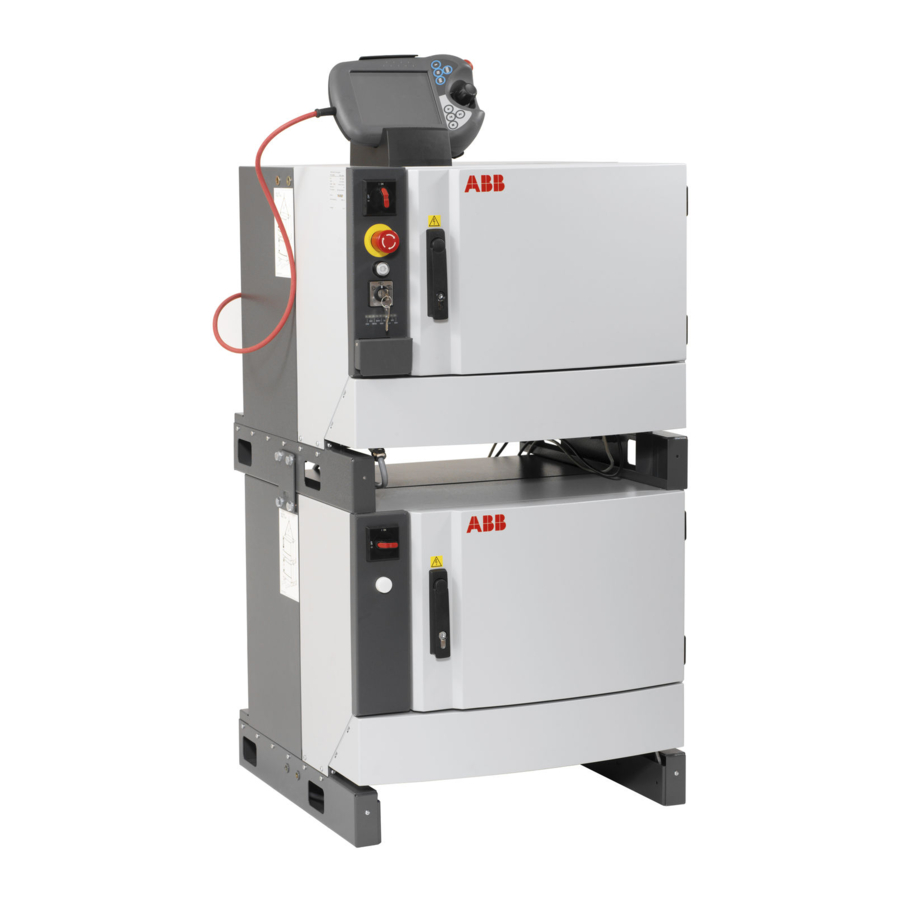
2 Installation and Commissioning, IRC5 2.1. Overview 2 Installation and Commissioning, IRC5 2.1. Overview General The ABB IRC5 controller is available in two basic configurations: Single Cabinet Controller and Dual Cabinet Controller. xx0600002929 Dual Cabinet (Control Module) Dual Cabinet (Drive Module) -
Page 38: Installation Activities
How to connect buses e.g DeviceNet, is detailed in the Application manual for the bus respectively. How to connect I/O units to the IRC5 controller is detailed in the Application manual for the I/O unit respectively. How to connect to a network is detailed in... -
Page 39: Transporting And Handling
2.3.1. Lifting the controller modules Lifting device Use the two lifting eyes or a fork lift when lifting the IRC5 controller, as shown below. The figure below shows the maximum angle between the lifting straps when lifting the controller. The weight of the controller modules are detailed in section... -
Page 40: Unpacking, Irc5 Controller
When unpacking the controller, check that it was not damaged during transport. NOTE! If the IRC5 Controller is going to be stored before unpacking and installation, read the following information regarding storage conditions. Storage conditions The table below shows the recommended storage conditions for the IRC5 Controller:... - Page 41 2 Installation and Commissioning, IRC5 2.3.2. Unpacking, IRC5 Controller Continued Equipment Protection class FlexPendant IP54 3HAC021313-001 Revision: K...
-
Page 42: On-Site Installation
2.4 On-site Installation 2.4.1. Required installation space, IRC5 Controller Dimensions The figure below shows the required installation space for the IRC5 controller, the illustration shows a Single Cabinet Controller. The measures are the same for the Dual Cabinet Controller. xx0500001848 NOTE! The free space on the right hand side of the controller is required to allow opening the door a full 180°... -
Page 43: Bolting Down The Controller
2 Installation and Commissioning, IRC5 2.4.2. Bolting down the controller 2.4.2. Bolting down the controller Bolt pattern, Single Cabinet Controller and Dual Cabinet Controller Design 2006 The figure below shows the bolt pattern for the Single Cabinet Controller: xx0500001853 Bolt pattern, Dual Cabinet Controller Design 2004 The figures below shows the bolt pattern for the Control Module and the Drive Module. -
Page 44: Transportation Screws
2 Installation and Commissioning, IRC5 2.4.3. Transportation screws 2.4.3. Transportation screws General During transportation the kick cover is secured with two screws. The two screws must be removed before removal of the plate and connection of cables. The screws are located as shown in the illustration below. -
Page 45: Mounting The Flexpendant Holder
2 Installation and Commissioning, IRC5 2.4.4. Mounting the FlexPendant holder 2.4.4. Mounting the FlexPendant holder Location The placement of the FlexPendant holder is shown in the illustration below. xx0500002542 FlexPendant holder mounted on top of the control cabinet. FlexPendant holder mounted on the control cabinet door. - Page 46 2 Installation and Commissioning, IRC5 2.4.4. Mounting the FlexPendant holder Continued Procedure - On top of the control cabinet The following procedure details how to mount the FlexPendant holder on top of the control cabinet. Action Note/illustration 1. Remove the protective liner from the tape.
- Page 47 2 Installation and Commissioning, IRC5 2.4.4. Mounting the FlexPendant holder Continued Procedure - On the control cabinet door The following procedure details how to mount the FlexPendant holder on the control cabinet door. Action Note/Illustration 1. At assembly of FlexPendant holder on the...
- Page 48 2 Installation and Commissioning, IRC5 2.4.4. Mounting the FlexPendant holder Continued Action Note/Illustration 5. Press the mounting plate against the control cabinet door. NOTE! The surface must be clean and dry. xx0700000243 3HAC021313-001 Revision: K...
-
Page 49: Connections
2.5 Connections 2.5.1. Connectors on controller, IRC5 General The following section describes the connectors on respective front panels on the IRC5 controller. These are described below. Single Cabinet Controller The following details the connection interface on the Single Cabinet Controller. - Page 50 2 Installation and Commissioning, IRC5 2.5.1. Connectors on controller, IRC5 Continued Large robots The following details the connection interface for large robots. Old connection interface: xx0500002044 New connection interface: xx0700000425 Description XP.0 Mains connection XS.1 Robot power connection XS.7 Additional axes power connection XS.58 Position switches...
- Page 51 2 Installation and Commissioning, IRC5 2.5.1. Connectors on controller, IRC5 Continued Dual Cabinet Controller The following details the connectors on the frontpanel of the Dual Cabinet Controller, that is the Control Module and the Drive Module. Control Module The following details the connectors on the frontpanel of the Control Module.
- Page 52 2 Installation and Commissioning, IRC5 2.5.1. Connectors on controller, IRC5 Continued Drive Module The following details the connectors on the frontpanel of the Drive Module. Small robots: xx0600002931 Large robots: xx0700000424 Description A4.X0: Mains connection to transformer A4.XS25: Power to Control Module A4.X1: Robot power connection...
-
Page 53: Connecting A Flexpendant
2 Installation and Commissioning, IRC5 2.5.2. Connecting a FlexPendant 2.5.2. Connecting a FlexPendant Location of FlexPendant connector The FlexPendant connector is located as shown below. xx0600002782 FlexPendant connector (A22.X1) On a Dual Cabinet Controller, the FlexPendant connector is located on the front of the Control Module. -
Page 54: Connecting A Pc To The Service Port
2 Installation and Commissioning, IRC5 2.5.3. Connecting a PC to the service port 2.5.3. Connecting a PC to the service port NOTE! The service port shall only be used for direct connection to a PC as described in this procedure. It must not be connected to a LAN (local area network), since it has a DHCP server that automatically distributes IP addresses to all units connected to the LAN. - Page 55 2 Installation and Commissioning, IRC5 2.5.3. Connecting a PC to the service port Continued Connections to ports may be done as detailed below: Connection to/from: Detailed in section: Connecting the Single Cabinet/Control Module to the factory LAN. Connecting a PC to the Single Cabinet/ Proceed as detailed below! Control Module service port.
- Page 56 2 Installation and Commissioning, IRC5 2.5.3. Connecting a PC to the service port Continued Connecting a PC to the service port Action Illustration 1. Make sure the network setting on the PC to Refer to the system documentation for be connected is correct.
-
Page 57: Connection To Serial Channel Connector
2 Installation and Commissioning, IRC5 2.5.4. Connection to serial channel connector 2.5.4. Connection to serial channel connector Overview The controller has one serial channel RS232 for permanent use which can be used for communication point to point with printers, terminals, computers or other equipment. - Page 58 2 Installation and Commissioning, IRC5 2.5.4. Connection to serial channel connector Continued Location DSQC639 The serial channel connector is placed on the computer unit as shown below. xx0600002892 Description COM1 Required equipment Equipment Note RS-232/422 converter DSQC 615 Computer unit DSQC 639 parts on page for spare part number.
- Page 59 2 Installation and Commissioning, IRC5 2.5.4. Connection to serial channel connector Continued Conversion of the RS232 channel The RS232 channel can be converted to RS422 full duplex with an optional adapter (Option 714-1). The RS422 enables a more reliable point to point communication (differential) over longer distances, from RS232 = 15m to RS422 = 120m.
-
Page 60: Connecting Power Supply To The Single Cabinet Controller
2 Installation and Commissioning, IRC5 2.5.5. Connecting power supply to the Single Cabinet Controller 2.5.5. Connecting power supply to the Single Cabinet Controller General The following sections details how to connect power supply to the Single Cabinet Controller. Location xx0500001869... - Page 61 2 Installation and Commissioning, IRC5 2.5.5. Connecting power supply to the Single Cabinet Controller Continued Action Note/Illustration 2. Fit the cable trough the cable gland and tighten. xx0500001870 Parts: • A: cable gland • B: rotary switch • C: cable pipe •...
- Page 62 2 Installation and Commissioning, IRC5 2.5.5. Connecting power supply to the Single Cabinet Controller Continued Action Note/Illustration 5. Route the phase wires through the pipe See illustration above. up to the rotary switch. 6. Connect the wires as shown in the illus- tration.
-
Page 63: Connecting Power Supply To The Dual Cabinet Controller
Control Module after delivery. Action Note/Illustrator 1. Lead the harness through the Connectors on the Control Module are described in cable gland, into the Control section, Connectors on controller, IRC5 on page 47 Cabinet. Continues on next page 3HAC021313-001 Revision: K... - Page 64 2 Installation and Commissioning, IRC5 2.5.6. Connecting power supply to the Dual Cabinet Controller Continued Action Note/Illustrator 2. Loosen the contact behind the main switch of the Control Cabinet. xx0600003367 A - Connect 3. Connect the two power cables from the harness to the contacts marked 1L1 and 3L2 on the contact.
-
Page 65: Connecting The Communication Cabling For The Dual Cabinet Controller
2 Installation and Commissioning, IRC5 2.5.7. Connecting the communication cabling for the Dual Cabinet Controller 2.5.7. Connecting the communication cabling for the Dual Cabinet Controller General Normally the communication cabling between the Control Module and Drive Module are installed at delivery. - Page 66 2 Installation and Commissioning, IRC5 2.5.7. Connecting the communication cabling for the Dual Cabinet Controller Continued Procedure The procedures below details how to install the communication cabling. The placement of Computer unit, Axis computer, Panel unit and Contactor board are described in the repairs section respectively.
-
Page 67: Fitting The Connector
2 Installation and Commissioning, IRC5 2.5.8. Fitting the connector 2.5.8. Fitting the connector General This section details how to fabricate a cable for connecting the mains power to the Drive Module. Specifications The following details the cable and fuse requirements for the mains power connection to the Drive Module. - Page 68 2 Installation and Commissioning, IRC5 2.5.8. Fitting the connector Continued Action Note/Illustration 3. Fit the cable through the hosing and the brass cable clamp, and connect the wires to the female connector. xx0400001044 • A: housing • B: Brass cable clamp •...
-
Page 69: Connecting The Manipulator To The Irc5 Controller
2.5.9. Connecting the manipulator to the IRC5 controller General Connect the manipulator and IRC5 controller to each other after installing them. The lists below specify which cables to be used in each application. All connectors on the IRC5 controller are shown in section... -
Page 70: The Motors On/Motors Off Circuit
2 Installation and Commissioning, IRC5 2.5.10. The MOTORS ON/MOTORS OFF circuit 2.5.10. The MOTORS ON/MOTORS OFF circuit Outline diagram The MOTORS ON/MOTORS OFF circuit is made up of two identical chains of switches. The diagram shows the available customer connections, AS, GS, SS and ES. - Page 71 2 Installation and Commissioning, IRC5 2.5.10. The MOTORS ON/MOTORS OFF circuit Continued Function of the MOTORS ON/MOTORS OFF circuit The circuit monitors all safety related equipment and switches. If any of the switches is opened, the MOTORS ON/MOTORS OFF circuit switches the power to the motors off.
- Page 72 2 Installation and Commissioning, IRC5 2.5.10. The MOTORS ON/MOTORS OFF circuit Continued Technical data per chain GS/AS/SS open "0" < 5 V External supply of GS/AS/SS Max. + 35 VDC Min. - 35 VDC GS/AS/SS Filter time 2,0 ms Max. potential in relation to the...
- Page 73 2 Installation and Commissioning, IRC5 2.5.10. The MOTORS ON/MOTORS OFF circuit Continued Connection of ES1/ES2 on panel unit The diagram below shows the terminals for the emergency circuits. The supply from internal 24V (X1/X2:10) and 0V (X1/X2:10) is displayed. For an ext.
- Page 74 2 Installation and Commissioning, IRC5 2.5.10. The MOTORS ON/MOTORS OFF circuit Continued Technical data ES1 and ES2 max output voltage 120 VAC or 48 VDC ES1 and ES2 max output current 120 VAC: 4 A 48 VDC L/R: 50 mA...
-
Page 75: Connection Of External Safety Relay
2 Installation and Commissioning, IRC5 2.5.11. Connection of external safety relay 2.5.11. Connection of external safety relay Description The motor contactors K42 and K43 in the Drive Module can operate with external equipment if external relays are used. The figure below shows an example of how to connect an external safety relay. -
Page 76: Connection To Motors On/Motors Off Contactor
2 Installation and Commissioning, IRC5 2.5.12. Connection to MOTORS ON/MOTORS OFF contactor 2.5.12. Connection to MOTORS ON/MOTORS OFF contactor General This section details connection to the MOTORS ON/MOTORS OFF contactor. To be used when the customer wants external equipment to follow the robot control. - Page 77 2 Installation and Commissioning, IRC5 2.5.12. Connection to MOTORS ON/MOTORS OFF contactor Continued Procedure Following procedure details connection to the MOTORS ON/MOTORS OFF contactor. Action Info/Illustration DANGER! Before any work inside the cabinet, please observe the safety information in section...
-
Page 78: Connection Of Drive Module Disconnect, By Limit Switch
2 Installation and Commissioning, IRC5 2.5.13. Connection of Drive Module Disconnect, by limit switch 2.5.13. Connection of Drive Module Disconnect, by limit switch General This function enables you to temporarily disconnect a Drive Module and deactivate any robot or additional mechanical units connected to this module. The procedures are detailed below. - Page 79 The following procedures details how to enabeling the system for a Drive Module Disconnect. Action 1. On the FlexPendant, Tap ABB and then Tap Control Panel. 2. In the Control panel menu, Tap Configuration. 3. In the Configuration menu, Tap Topics, and select Motion.
- Page 80 2 Installation and Commissioning, IRC5 2.5.13. Connection of Drive Module Disconnect, by limit switch Continued Action Note/illustration 2. Disconnect the connector X22. It is also possible to use connector X21, but this is typically used for limit switches on the robot.
- Page 81 2 Installation and Commissioning, IRC5 2.5.13. Connection of Drive Module Disconnect, by limit switch Continued Action Note/illustration 3. Connect the wires to the connector X22 according to the diagram on the right. xx0500002091 3HAC021313-001 Revision: K...
-
Page 82: Connection Of Servo Disconnect, By Servo Power Switch
2.5.14. Connection of servo disconnect, by servo power switch 2.5.14. Connection of servo disconnect, by servo power switch General The IRC5 controller is pre-wired to accept a customer servo disconnect. NOTE! Due to risk of voltage drop, the switch to the servo disconnect circuit should not be mounted more than 50 meters from the Drive Module. - Page 83 2 Installation and Commissioning, IRC5 2.5.14. Connection of servo disconnect, by servo power switch Continued WARNING! It is recommmended to also open the 24V to the brake (wire 489) to avoid accidental release of the brakes when the drive system is disconnected.
-
Page 84: Connecting A Limit Switch Override Push Button
The following procedure details how to connect a Limit switch override circuit in a Single Cabinet Controller. Action Note/illustration Danger DANGER! Before any work inside the IRC5 controller modules, please observe the safety information in section DANGER - Make sure that the main power has been switched off! on page... - Page 85 2 Installation and Commissioning, IRC5 2.5.15. Connecting a Limit switch override push button Continued Action Note/illustration 2. Attach two additional contact blocks on the existing push button (Motors on). note Note! There is only room for one additional contact block beside the two existing.
- Page 86 2 Installation and Commissioning, IRC5 2.5.15. Connecting a Limit switch override push button Continued Action Note/illustration 4. Route the wires together with the existing harness on the left wall. xx0500002557 • A: Contact blocks • B: Wires • C: Connector X23 5.
- Page 87 The following procedure details how to connect a Limit switch override circuit in a Dual Cabinet Controller. Action Note/illustration Danger DANGER! Before any work inside the IRC5 controller modules, please observe the safety information in section DANGER - Make sure that the main power has been switched off! on page 2.
- Page 88 2 Installation and Commissioning, IRC5 2.5.15. Connecting a Limit switch override push button Continued Action Note/illustration 6. Connect wires from the contact blocks to the connector according to the diagram to the right. xx050000 7. Route the wires together with the existing harness on the left wall.
-
Page 89: Drive System
2.6 Drive system 2.6.1. Drive functions, general General The manipulator is powered by power electronics found in the IRC5 controller, (for the Dual Cabinet Controller it’s found in the Drive Module). This also includes power electronics for driving external axes. -
Page 90: Configuration Of The Drive System, Irc5
2.6.2. Configuration of the drive system, IRC5 General The IRC5 Single Cabinet Controller contains a number of drive units, rectifiers and filters. Any allowed combination of these, depending on the robot type, is specified below. The robot system may also be equipped with up to three additional drive modules, which are described in the Product manual - IRC5, section Installation of additional drive module. - Page 91 2 Installation and Commissioning, IRC5 2.6.2. Configuration of the drive system, IRC5 Continued IRB 140 The figures show the drive unit with and without additional axes respectively. The table specifies which units may be fitted in which positions. xx0200000121 xx0200000120 Pos.
- Page 92 2 Installation and Commissioning, IRC5 2.6.2. Configuration of the drive system, IRC5 Continued IRB 340, 360 The figures show the drive unit with and without additional axes respectively. The table specifies which units may be fitted in which positions. xx0200000121 xx0200000120 Pos.
- Page 93 2 Installation and Commissioning, IRC5 2.6.2. Configuration of the drive system, IRC5 Continued IRB 1400 The figures show the drive unit with and without additional axes respectively. The table specifies which units may be fitted in which positions. xx0200000121 xx0200000120 Pos.
- Page 94 2 Installation and Commissioning, IRC5 2.6.2. Configuration of the drive system, IRC5 Continued IRB 2400 The figures show the drive unit with and without additional axes respectively. The table specifies which units may be fitted in which positions. xx0200000121 xx0200000120 Pos.
- Page 95 2 Installation and Commissioning, IRC5 2.6.2. Configuration of the drive system, IRC5 Continued IRB 4400 The figures show the drive unit with and without additional axes respectively. The table specifies which units may be fitted in which positions. Rectifier: Z2...
- Page 96 2 Installation and Commissioning, IRC5 2.6.2. Configuration of the drive system, IRC5 Continued Pos. Identification Description Art. no. Note DSQC 620_C4 Capacitor unit 3HAC14551-3 DSQC 618_R2 Rectifier 3HAC14549-2 Y2, X2 DSQC 619 Optional drive units 3HAC14550-4 Size: 1W for external axes...
- Page 97 2 Installation and Commissioning, IRC5 2.6.2. Configuration of the drive system, IRC5 Continued Designation in Template file name Main drive unit Power stage circuit diagram (drive unit name) DSQC 617_2E2C2B • M1 (R,S,T) M1 (DMX) Used for irb 1400, 1600, 2400 •...
-
Page 98: Memory Functions
RAM memory (memory modules fitted on the main computer motherboard) Computer units Computer unit DSQC623: • Computer Module BD plus features a hard disk drive containing ABB VxWorks boot image software. • Computer Module AC plus features a IDE Flash Module 256MB drive containing ABB VxWorks boot image software. -
Page 99: Connecting A Usb Memory To The Computer Unit
2 Installation and Commissioning, IRC5 2.7.2. Connecting a USB memory to the computer unit 2.7.2. Connecting a USB memory to the computer unit Location DSQC623 A USB memory may be connected to either one of the USB ports on the computer unit. The... - Page 100 2 Installation and Commissioning, IRC5 2.7.2. Connecting a USB memory to the computer unit Continued Location DSQC639 A USB memory may be connected to either one of the USB ports on the computer unit. The USB ports are shown in the figure below: xx0600002895 USB 1, 2 The USB connectors provide two legacy USB 2.0 ports supporting High...
- Page 101 Do not disconnect the USB memory approx. 10 seconds unit just as any other hard after connecting it. drive unit. CAUTION! CAUTION! Handling of USB memory is described in Operating manual - IRC5 with FlexPendant, section File Managing. 3HAC021313-001 Revision: K...
-
Page 102: I/O System
The IRC5 controller may be fitted with I/O, Gateway or Encoder units. These are configured in an identical way. The IRC5 Single Cabinet Controller is prepared for up to two I/O units, Gateways or Encoder interfaces units, and the Dual Cabinet Controller (Control Module) is prepared for up to four I/O units, Gateways or Encoder interface units. - Page 103 2 Installation and Commissioning, IRC5 2.8.1. Definition of I/O units, IRC5 Continued I/O units The table below specifies the I/O units: Description Note AD Combi I/O DSQC 651 I/O System parts on page 323 for the spare part number Digital I/O...
-
Page 104: Installation Of Add-Ons
2.9.1. Installation of additional Drive Module General To be able to use a Multi Move system or to control more than 3 additional axes, an additional Drive Module is needed. The IRC5 controller is prepared for up to three additional Drive Modules. xx0400001042... - Page 105 2 Installation and Commissioning, IRC5 2.9.1. Installation of additional Drive Module Continued Action Info/Illustration WARNING! The unit is sensitive to ESD, before handling the unit please observe the safety information in section WARNING - The unit is sensitive to ESD! on page 29 3.
- Page 106 2 Installation and Commissioning, IRC5 2.9.1. Installation of additional Drive Module Continued Action Info/Illustration 6. Loosen the attachment screws, and remove the cover to a empty slot in the back of the controller. xx0500001888 • A: cover • B: attachment screw (2pcs) 7.
- Page 107 2 Installation and Commissioning, IRC5 2.9.1. Installation of additional Drive Module Continued Action Info/Illustration 8. Connect the ethernet cable (A32.X9) to the DSQC 612 Ethernet board. Connector: • A32.X9 to Ethernet board connector, AXC1 9. Connect the safety signal cable (A21.X7) to the Panel board.
-
Page 108: Installation Of External Operator's Panel, Irc5
2 Installation and Commissioning, IRC5 2.9.2. Installation of external operator's panel, IRC5 2.9.2. Installation of external operator's panel, IRC5 Location An external operator's panel may be fitted in a separate wall cabinet as shown in the illustration below. xx0400000956 Wall cabinet IRC5... - Page 109 2 Installation and Commissioning, IRC5 2.9.2. Installation of external operator's panel, IRC5 Continued Procedure The procedure below details how to install the external control panel. Action Info/Illustration DANGER! Before any work inside the cabinet, please observe the safety information in section...
- Page 110 2 Installation and Commissioning, IRC5 2.9.2. Installation of external operator's panel, IRC5 Continued Action Info/Illustration 4. Remove the cover to a free customer The illustration below shows the connector slot on the connection panel. connection panel for the Dual Cabinet Controller.
- Page 111 2 Installation and Commissioning, IRC5 2.9.2. Installation of external operator's panel, IRC5 Continued Action Info/Illustration 7. Connect the ethernet connector A32.A8 to DSQC623: the computer unit. Slot 1 Slot 2 Slot 3 Slot 4 Slot 5 xx0400000960 • A: Connector X8...
- Page 112 2 Installation and Commissioning, IRC5 2.9.2. Installation of external operator's panel, IRC5 Continued Action Info/Illustration 8. Connect the signal connectors A21.X9 and A21.X10 to the connector X9 and X10 on the panel board unit. xx0500001890 xx0600003257 9. Strap the cabling to the existing cable straping inside the module.
-
Page 113: Installation Of Drive System Parts
Art. no. Note A number of choices are Specified in section Configuration available of the drive system, IRC5 on page Standard toolkit The contents are defined in section Standard toolkit. Other tools and procedures may These procedures include be required. See references to references to the tools required. - Page 114 • C: attachment screw 3. Fit the drive unit in position. Allowed positions are specified in section Configuration of the drive system, IRC5 Secure it with its attachment screws. on page 88 4. Connect any additional connectors to the unit.
-
Page 115: Installation Of I/O, Gateways And Encoder Interface Units, Irc5
2 Installation and Commissioning, IRC5 2.9.4. Installation of I/O, Gateways and encoder interface units, IRC5 2.9.4. Installation of I/O, Gateways and encoder interface units, IRC5 Location in Single Cabinet Controller The location for the I/O units, Gateway or encoder interface units to be installed are shown in the illustration below. - Page 116 2 Installation and Commissioning, IRC5 2.9.4. Installation of I/O, Gateways and encoder interface units, IRC5 Continued Fitting The procedure below details how to fit the units. Action Note/Illustration DANGER! Before any work inside the cabinet, please observe the safety information in section...
-
Page 117: Installation Of Pmc-Card For Force Control Function
2 Installation and Commissioning, IRC5 2.9.5. Installation of PMC-card for Force Control Function 2.9.5. Installation of PMC-card for Force Control Function Location The PMC-card shall be mounted on the axis computer card. The axis computer is located as shown in the illustration below. - Page 118 2 Installation and Commissioning, IRC5 2.9.5. Installation of PMC-card for Force Control Function Continued Equipment Art. no. Note Circuit diagram Circuit Diagram on page 341 Procedures The following procedures details how to install the PMC-card on the axis computer card.
- Page 119 2 Installation and Commissioning, IRC5 2.9.5. Installation of PMC-card for Force Control Function Continued Action Note/illustration 4. Remove the six attachments screws on the sides of the axis computer, and remove the back cover. xx0500002134 • A: back cover •...
- Page 120 2 Installation and Commissioning, IRC5 2.9.5. Installation of PMC-card for Force Control Function Continued Action Note/illustration 7. Refit the axis computer in controller. xx0500001885 • A: axis computer • B: attachment screws 8. Install the Force Control software. Installation of the software is...
-
Page 121: Installation Of Extra Mass Memory In Computer Unit Dsqc623
2 Installation and Commissioning, IRC5 2.9.6. Installation of extra mass memory in computer unit DSQC623 2.9.6. Installation of extra mass memory in computer unit DSQC623 Location The mass memory is located in the Computer unit as shown in the figure below. - Page 122 2 Installation and Commissioning, IRC5 2.9.6. Installation of extra mass memory in computer unit DSQC623 Continued Procedure Hard disk drive The procedure below details how to install the extra mass memory. Action Info/Illustration DANGER! Before any work inside the cabinet, please...
- Page 123 2 Installation and Commissioning, IRC5 2.9.6. Installation of extra mass memory in computer unit DSQC623 Continued Action Info/Illustration 7. Disconnect the flat ribbon cable from the IDE connector on the motherboard. xx0400000895 • A: IDE connector 8. Connect the included flat ribbon cable to the IDE connector on the motherboard.
- Page 124 2 Installation and Commissioning, IRC5 2.9.6. Installation of extra mass memory in computer unit DSQC623 Continued Action Note/illustration WARNING! The unit is sensitive to ESD, before handling the unit please observe the safety information in section WARNING - The unit is sensitive to ESD! on page 29 3.
-
Page 125: Installation Of Euromap And Spi
(similar to EM 67). The robot interface for Euromap 67 and SPI - AN 146 is implemented in the standard IRC5 controller. For Euromap 12 and SPI - AN 116 an additional converter box outside the cabinet is plugged on the Euromap 67 interface. - Page 126 2 Installation and Commissioning, IRC5 2.9.7. Installation of Euromap and SPI Continued Relay 24K1 and Relay 24K2 Position switch terminal XT13 Euromap 67: Digital 24 VDC I/O (I/O 1) Euromap 12 and SPI: Digital Relay Connector XS13 Location of Euromap harness in the Dual Cabinet xx0500002634 Connector A21.X5, on Panel board...
- Page 127 2 Installation and Commissioning, IRC5 2.9.7. Installation of Euromap and SPI Continued Equipment Art. number Description Note Cabling 3HAC024069-001 internal in cabinet Dual Cabinet Converter box bracket eio.cfg pre-configured file Available in RW CD/Utility Cable 3HAC024328-001 external cable 10m Option 673-1...
- Page 128 2 Installation and Commissioning, IRC5 2.9.7. Installation of Euromap and SPI Continued Action Note/Illustration 3. Remove the original adapter plate on the front of the controller. xx0600002652 • A: original adapter plate • B: attachment screw (8 pcs) 4. Fit the included adapter plate.
- Page 129 2 Installation and Commissioning, IRC5 2.9.7. Installation of Euromap and SPI Continued Action Note/Illustration 8. Connect the connectors X1, X2 and X5 on the panel board. xx0500001890 9. Connect the wires no. 1002 and no. 1019 to the "Mould area free" (Euromap) or light barrier and safety relay.
- Page 130 2 Installation and Commissioning, IRC5 2.9.7. Installation of Euromap and SPI Continued Installation of internal harness (Euromap 67) in the Dual Cabinet Controller The following procedure details how to install the internal harness (Euromap 67) in the Dual Cabinet Controller.
- Page 131 2 Installation and Commissioning, IRC5 2.9.7. Installation of Euromap and SPI Continued Action Note/Illustration 5. Fit the harness through the connector hole on the adapter plate, and fit the connector XS13 with the attachment screws. xx0600002654 • A: connector XS13 •...
- Page 132 2 Installation and Commissioning, IRC5 2.9.7. Installation of Euromap and SPI Continued Action Note/Illustration 12. Connect the connectors X1, X2, X3 and X4 on See the location of I/O 2 in Location of I/O 2. Euromap harness in the Dual Cabinet on page 124.
-
Page 133: Upgrading And Installation Of 2X Euromap Interface (Option 671-4)
2.9.8. Upgrading and installation of 2X Euromap interface (Option 671-4) General This section describes installation of 2X Euromap interface (Option 671-4) in an IRC5 Single Cabinet Controller and in an IRC5 Dual Cabinet Controller. The customer option 2X Euromap interface is not a pre mounted delivery option, it must be complimented with a safety relay, not included in the option kit from ABB. - Page 134 2 Installation and Commissioning, IRC5 2.9.8. Upgrading and installation of 2X Euromap interface (Option 671-4) Continued Cable protection Euromap adapter X13x and X14z connector Placement of customer safety relay Location of Euromap 2X interfaces in the Dual Cabinet xx0800000215 Connector A21.X5, on panel board Connector A21.X1, on panel board...
- Page 135 2 Installation and Commissioning, IRC5 2.9.8. Upgrading and installation of 2X Euromap interface (Option 671-4) Continued Required equipment for 2X Euromap interfaces in the Single Cabinet Controller Equipment Art. number Description Note Cable harness 3HAC026692-001 Harness-Euromap 67 Single Cab. Gasket...
- Page 136 2 Installation and Commissioning, IRC5 2.9.8. Upgrading and installation of 2X Euromap interface (Option 671-4) Continued Action Note/Illustration 3. Before assembling the harness 2, disconnect X31.1, X31.2 and X31.3 and discard the harness with the connectors X1, X2 and X5 for the panel board.
- Page 137 2 Installation and Commissioning, IRC5 2.9.8. Upgrading and installation of 2X Euromap interface (Option 671-4) Continued Action Note/Illustration 8. Connect the harness from the Connectors X13.1, X13.2 and X13.3, described in panel board to the adapter. section Adapter Euromap 67 on page 137.
- Page 138 WARNING - The unit is sensitive to ESD! on page 3. Assemble the relay (customer supplied) on the recommended location in the IRC5 Controller. 4. Connect all wires from the adapter. Described in section Wiring Relay.
- Page 139 2 Installation and Commissioning, IRC5 2.9.8. Upgrading and installation of 2X Euromap interface (Option 671-4) Continued Adapter Euromap 67 The figure below shoes the connections for the Euromap 67 adapter 3HAC032370-001. xx0800000216 Wiring adapter Harness Connection From-To Connection XS13.1 X13-Adapter XP13.1...
- Page 140 2 Installation and Commissioning, IRC5 2.9.8. Upgrading and installation of 2X Euromap interface (Option 671-4) Continued Wiring relay The figure below shoes the connections for the Euromap safety loop. xx0800000219 Connection point A Connection point B Wire No. Term Term...
-
Page 141: Installation Of Cooling Fan Harness Axis 1 And 2
2 Installation and Commissioning, IRC5 2.9.9. Installation of cooling fan harness axis 1 and 2 2.9.9. Installation of cooling fan harness axis 1 and 2 General If the robot is going to be supplemented with cooling fans on axis 1 and 2 the controller has to be supplemented with a internal harness. - Page 142 2 Installation and Commissioning, IRC5 2.9.9. Installation of cooling fan harness axis 1 and 2 Continued Locations in Single Cabinet Controller xx0600002686 Harness, cooling - Axis 1 and 2 Cable protection Contactor interface board Connector A43.X10 Connector A43.X11 Position switch terminals...
- Page 143 2 Installation and Commissioning, IRC5 2.9.9. Installation of cooling fan harness axis 1 and 2 Continued Procedures for Dual Cabinet Controller Following procedure details how to install the harness, cooling - Axis 1 and 2 kit in the Dual Cabinet Controller.
- Page 144 2 Installation and Commissioning, IRC5 2.9.9. Installation of cooling fan harness axis 1 and 2 Continued Action Note/Illustration 7. Connect the harness connectors to the contactor interface board. • A43.X11 to X11 • A43.X10 to X10 xx0500002690 Locations in Dual Cabinet Controller on page 139.
- Page 145 2 Installation and Commissioning, IRC5 2.9.9. Installation of cooling fan harness axis 1 and 2 Continued Action Note/Illustration 5. Route the cable to the left and connect the harness connectors to the contactor interface board. • A43.X11 to X11 •...
-
Page 146: Installation Of Hot Plug
2 Installation and Commissioning, IRC5 2.9.10. Installation of Hot plug 2.9.10. Installation of Hot plug Location To be able to use the Hot plug function an additional hot plug button is needed. The figure below shows the location of the hot plug button on the Single Cabinet Controller and Dual Cabinet Controller. - Page 147 2 Installation and Commissioning, IRC5 2.9.10. Installation of Hot plug Continued Procedure Single Cabinet Controller The procedure below details how to install the hot plug button in the Single Cabinet Controller. Action Note/Illustration DANGER! Before any work inside the cabinet, please...
- Page 148 2 Installation and Commissioning, IRC5 2.9.10. Installation of Hot plug Continued Action Note/Illustration 4. Disconnect signal cabling from the panel board unit. xx0600002946 • A: Connector X10 5. Remove the FlexPendant connector with harness from the Operator panel. xx0600002948 •...
- Page 149 2 Installation and Commissioning, IRC5 2.9.10. Installation of Hot plug Continued Action Note/Illustration 10. Connect the cables to the hot plug button connector. xx0600002953 11. Place the warning label above the hot plug button. xx0600002957 • A: Warning label 12. Test the hot plug button function.
- Page 150 2 Installation and Commissioning, IRC5 2.9.10. Installation of Hot plug Continued Procedure Dual Cabinet Controller The procedure below details how to install the hot plug button in the Dual Cabinet Controller. Action Note/Illustration DANGER! Before any work inside the cabinet, please...
- Page 151 2 Installation and Commissioning, IRC5 2.9.10. Installation of Hot plug Continued Action Note/Illustration 4. Disconnect signal cabling from the panel board unit. xx0600002946 • A: Connector X10 5. Remove the cover plate with the FlexPendant connector and harness. xx0600002954 •...
- Page 152 2 Installation and Commissioning, IRC5 2.9.10. Installation of Hot plug Continued Action Note/Illustration 9. Connect the cables to the hot plug button connector. xx0600002956 10. Place the warning label below the hot plug button. xx0600002955 • A: Warning label 11. Test the hot plug button function.
- Page 153 2 Installation and Commissioning, IRC5 2.9.10. Installation of Hot plug Continued Action Note/Illustration 4. Keep pressing the hot plug button and at the same time, switch the jumper plug with the FlexPendant plug. • Verify that the system still has motors on.
-
Page 154: Installing The Eps Board Dsqc 646 For Electronic Position Switches
2 Installation and Commissioning, IRC5 2.9.11. Installing the EPS board DSQC 646 for Electronic Position Switches 2.9.11. Installing the EPS board DSQC 646 for Electronic Position Switches General To use the option Electronic Position Switches you need to install an EPS board in the robot controller. - Page 155 2 Installation and Commissioning, IRC5 2.9.11. Installing the EPS board DSQC 646 for Electronic Position Switches Continued Procedure The procedure below details how to install an EPS board. Action Note/illustration DANGER! Before any work inside the cabinet, please observe the safety information in section...
- Page 156 2 Installation and Commissioning, IRC5 2.9.11. Installing the EPS board DSQC 646 for Electronic Position Switches Continued Action Note/illustration 5. Remove the attachment screws of the axis computer. xx0500002002 • A: axis computer • B: attachment screws 6. Lift out the axis computer so that the EPS board can be fitted behind the axis computer.
- Page 157 2 Installation and Commissioning, IRC5 2.9.11. Installing the EPS board DSQC 646 for Electronic Position Switches Continued Action Note/illustration 8. Fit the axis computer on the EPS board. xx0600003206 • A: axis computer • B: EPS board • C: attachment screws 9.
- Page 158 2 Installation and Commissioning, IRC5 2.9.11. Installing the EPS board DSQC 646 for Electronic Position Switches Continued Action Note/illustration 10. Remove the SMB cable from the axis computer and connect it to the EPS board. Connect the SMB cable from the EPS board to the axis computer.
- Page 159 2 Installation and Commissioning, IRC5 2.9.11. Installing the EPS board DSQC 646 for Electronic Position Switches Continued Action Note/illustration 12. Connect signal cables to the plug contact, which is then connected to the I/O connector of the EPS board. •...
-
Page 160: Installing The Safemove Board Dsqc 647
2 Installation and Commissioning, IRC5 2.9.12. Installing the SafeMove board DSQC 647 2.9.12. Installing the SafeMove board DSQC 647 General To use the option SafeMove you need to install an SafeMove board DSQC 647 in the robot controller. The procedure below will show how to install this board. - Page 161 2 Installation and Commissioning, IRC5 2.9.12. Installing the SafeMove board DSQC 647 Continued Procedure The procedure below details how to install the SafeMove board. Action Note/illustration DANGER! Before any work inside the cabinet, please observe the safety information in section...
- Page 162 2 Installation and Commissioning, IRC5 2.9.12. Installing the SafeMove board DSQC 647 Continued Action Note/illustration 4. Connect both SMB cables and both Ethernet cables to the SafeMove board before mounting the board. These connections may be difficult to reach once the board is mounted.
- Page 163 2 Installation and Commissioning, IRC5 2.9.12. Installing the SafeMove board DSQC 647 Continued Action Note/illustration 7. Fit the SafeMove board in the same place as the axis computer was before. xx0800000104 • A: SafeMove board • B: attachments screws (4 pcs) 8.
- Page 164 2 Installation and Commissioning, IRC5 2.9.12. Installing the SafeMove board DSQC 647 Continued Action Note/illustration 9. For a Single Cabinet Controller: Remove the Ethernet cable between the main computer and the axis computer. Replace it with the long Ethernet cable from the SafeMove board to the main computer.
- Page 165 2 Installation and Commissioning, IRC5 2.9.12. Installing the SafeMove board DSQC 647 Continued Action Note/illustration 11. Connect the SMB cables from the SafeMove board to the axis computer xx0800000032 • A: SMB1 cable • B: SMB2 cable 12. Disconnect the power cable from the axis computer and connect it to the split cable.
- Page 166 2 Installation and Commissioning, IRC5 2.9.12. Installing the SafeMove board DSQC 647 Continued Action Note/illustration 13. Connect the limit switch cable between the SafeMove board: SafeMove board (X13) and the contactor interface board (X21) xx0800000033 Contactor interface board: xx0800000105 •...
- Page 167 2 Installation and Commissioning, IRC5 2.9.12. Installing the SafeMove board DSQC 647 Continued Action Note/illustration 15. Connect signal cables to the plug contacts, which is then connected to the I/O connector of the SafeMove board. xx0700000640 • A: Power supply •...
-
Page 168: Installation Of Remote Service
2 Installation and Commissioning, IRC5 2.9.13. Installation of Remote Service 2.9.13. Installation of Remote Service General To use the option Remote Service you need a Remote Service box mounted in the robot controller. The procedure below will show how to connect the Remote Service antenna. - Page 169 2 Installation and Commissioning, IRC5 2.9.13. Installation of Remote Service Continued Procedure The following procedure details how to connect the Remote Service antenna. Action Note/illustration 1. Connect the antenna cable to the adapter cover plate on the controller. Use tightening torque 0.8 - 1.1 Nm.
- Page 170 2 Installation and Commissioning, IRC5 2.9.13. Installation of Remote Service 3HAC021313-001 Revision: K...
-
Page 171: Maintenance Activities, Controller Irc5
3.1. Maintenance schedule, controller IRC5 3 Maintenance activities, controller IRC5 3.1. Maintenance schedule, controller IRC5 General The IRC5 robot controller must be maintained at regular intervals to ensure its function. The maintenance activities and their respective intervals are specified below: Intervals Maintenance... -
Page 172: Inspection Activities
Inspection The procedure below details how to inspect the IRC5 controller. WARNING! Please observe the following before commencing any repair work on the IRC5 Controller modules or units connected to the controller: • Switch off all electric power supplies with the power switches on the Control and Drive modules! •... - Page 173 3 Maintenance activities, controller IRC5 3.2.1. Inspection of the controller Continued Action Note/Illustration 4. Inspect the drive system fans and air channels in the controller to make sure they are clean. xx0500002172 • A: drive system fans (4 pcs) 5. After cleaning:...
-
Page 174: Changing/Replacing Activities
3 Maintenance activities, controller IRC5 3.3.1. Activities 3.3 Changing/replacing activities 3.3.1. Activities References Certain activities to be performed as specified in the Maintenance Schedule are not all detailed in this chapter, but in the Repairs chapter. Please refer to the Repair chapter of the equipment in question. -
Page 175: Replacement Of Moist Dust Filter
3 Maintenance activities, controller IRC5 3.3.2. Replacement of moist dust filter 3.3.2. Replacement of moist dust filter Location The moist dust filters are located as shown in the illustration below. xx0700000128 Moist dust filter magazine Single Cabinet Controller Dual Cabinet Controller, Control Module... - Page 176 3 Maintenance activities, controller IRC5 3.3.2. Replacement of moist dust filter Continued Removal The procedure below details how to replace the moist dust filter. Action Note/Illustration 1. Pull the moist dust filter magazine upwards. xx0700000131 2. Pull the moist dust filter magazine in the arrow direction and remove it.
- Page 177 3 Maintenance activities, controller IRC5 3.3.2. Replacement of moist dust filter Continued Refitting The procedure below details how to refit the moist dust filter. Action Note/Illustration 1. Fit the new moist dust filter in the magazine and lock it with the lock shackle.
-
Page 178: Cleaning Activities
300. compressed air to clean the channels. 4. If the IRC5 controller is installed in a very harsh envi- How to remove the drive units is ronment, the drive units cooling fans must be cleaned detailed in section, at regular intervals. -
Page 179: Cleaning Moist Dust Filter
3 Maintenance activities, controller IRC5 3.4.2. Cleaning moist dust filter 3.4.2. Cleaning moist dust filter Location The moist dust filters are located as shown in the illustration below. xx0700000128 Moist dust filter magazine Single Cabinet Controller Dual Cabinet Controller, Control Module... - Page 180 3 Maintenance activities, controller IRC5 3.4.2. Cleaning moist dust filter Continued Action Note/Illustration 4. Refit the moist dust filter. How to refit the moist dust filter is detailed in section Replacement of moist dust filter on page 173. 3HAC021313-001 Revision: K...
-
Page 181: Cleaning The Flexpendant
3 Maintenance activities, controller IRC5 3.4.3. Cleaning the FlexPendant 3.4.3. Cleaning the FlexPendant Location The surfaces to clean are shown in the illustration below. xx0400000973 Touch screen Hard buttons Required equipment Equipment, etc. Note Soft cloth ESD Protected Warm water/Mild cleaning agent Clean the touch screen This section details how to clean the touch screen. - Page 182 3 Maintenance activities, controller IRC5 3.4.3. Cleaning the FlexPendant Continued Action Info/Illustration 2. Tap the Lock button in the following window. en0400000657 3. When the next window appers, it is safe to clean the screen. en0400000658 4. Clean the touch screen and...
- Page 183 3 Maintenance activities, controller IRC5 3.4.3. Cleaning the FlexPendant Continued Do's and don'ts! The section below specifies some special considerations when cleaning the FlexPendant. Always: • use ESD Protection • use cleaning equipment as specified above! Any other cleaning equipment may shorten the life time of the touch screen.
- Page 184 3 Maintenance activities, controller IRC5 3.4.3. Cleaning the FlexPendant 3HAC021313-001 Revision: K...
-
Page 185: Repair Activities, Controller Irc5
4 Repair activities, controller IRC5 4.1. Overview 4 Repair activities, controller IRC5 4.1. Overview General The ABB IRC5 controller is available in two basic configurations: Single Cabinet Controller and Dual Cabinet Controller. xx0600002929 Dual Cabinet (Control Module) Dual Cabinet (Drive Module) -
Page 186: Replacement Of Panel Board
4 Repair activities, controller IRC5 4.2. Replacement of panel board 4.2. Replacement of panel board Location The panel board unit is located as shown in the illustration below. In the Dual Cabinet Controller the panel board unit is located in the Control Module. - Page 187 4 Repair activities, controller IRC5 4.2. Replacement of panel board Continued Removal The procedure below details how to remove the panel board unit. Action Note/Illustration DANGER! Before any work inside the cabinet, please observe the safety information in section DANGER - Make...
- Page 188 4 Repair activities, controller IRC5 4.2. Replacement of panel board Continued Refitting The procedure below details how to refit the panel board unit. Action Note/Illustration DANGER! Before any work inside the cabinet, please observe the safety information in section DANGER - Make...
-
Page 189: Replacement Of Power Supply
4 Repair activities, controller IRC5 4.3.1. Replacement of control power supply 4.3 Replacement of power supply 4.3.1. Replacement of control power supply Location The control power supply is located on the left hand side as shown in the illustration below. - Page 190 4 Repair activities, controller IRC5 4.3.1. Replacement of control power supply Continued Equipment Spare part no. Art. no. Note Circuit Diagram 3HAC024480-004 Complete control system Removal The procedures below details how to remove the control power supply. Action Note/Illustration DANGER!
- Page 191 4 Repair activities, controller IRC5 4.3.1. Replacement of control power supply Continued Action Note/Illustration 2. Refit the new power supply unit by pushing it upward to fit the cap nut. Refit the control power supply by pull it down to fit the cap nut.
-
Page 192: Replacement Of Power Distribution Board
4 Repair activities, controller IRC5 4.3.2. Replacement of power distribution board 4.3.2. Replacement of power distribution board General In the Single Cabinet Controller the control power supply DSQC 604 will be replaced by the power distribution board DSQC 662. The replacement will start from August 2007. - Page 193 4 Repair activities, controller IRC5 4.3.2. Replacement of power distribution board Continued Equipment Spare part no. Art. no. Note Other tools and procedures may be required. See references to these procedures in the step-by- step instructions below. Circuit diagram 3HAC024480-004 Removal The procedure below details how to remove the power distribution board.
- Page 194 4 Repair activities, controller IRC5 4.3.2. Replacement of power distribution board Continued Refitting The procedure below details how to refit the power distribution board. Action Note/Illustration DANGER! Before any work inside the cabinet, please observe the safety information in section...
-
Page 195: Replacement Of Customer I/O Power Supply, Irc5
4 Repair activities, controller IRC5 4.3.3. Replacement of customer I/O power supply, IRC5 4.3.3. Replacement of customer I/O power supply, IRC5 Location The customer I/O power supply is located as shown in the illustration below. For the Dual Cabinet Controller the customer I/O power supply is located in the Control Module with the same placement. - Page 196 4 Repair activities, controller IRC5 4.3.3. Replacement of customer I/O power supply, IRC5 Continued Equipment Spare part no. Art. no. Note Circuit Diagram 3HAC024480-004 Complete control system Removal The procedure below details how to remove the customer I/O power supply.
- Page 197 4 Repair activities, controller IRC5 4.3.3. Replacement of customer I/O power supply, IRC5 Continued Refitting The procedure below details how to refit the customer I/O power supply. Action Note/Illustration DANGER! Before any work inside the cabinet, please observe the safety information in section...
-
Page 198: Replacement Of Customer I/O Power Supply
4 Repair activities, controller IRC5 4.3.4. Replacement of customer I/O power supply 4.3.4. Replacement of customer I/O power supply General In the Single Cabinet Controller and Dual Cabinet Controller the customer I/O power supply DSQC 608 will be replaced by the customer I/O power supply DSQC 609. The replacement will start from August 2007. - Page 199 4 Repair activities, controller IRC5 4.3.4. Replacement of customer I/O power supply Continued Equipment Spare part no. Art. no. Note Standard toolkit The contents are defined in section Standard toolkit. Other tools and procedures These procedures may be required. See...
- Page 200 4 Repair activities, controller IRC5 4.3.4. Replacement of customer I/O power supply Continued Refitting The procedure below details how to refit the customer I/O power supply. Action Note/Illustration DANGER! Before any work inside the cabinet, please observe the safety information in section...
-
Page 201: Replacement Of Drive System Power Supply
4 Repair activities, controller IRC5 4.3.5. Replacement of drive system power supply 4.3.5. Replacement of drive system power supply Location The illustration below shows the location of the drive system power supply in a Single Cabinet Controller. In the Dual Cabinet Controller the drive system power supply is located in the Drive Module. - Page 202 4 Repair activities, controller IRC5 4.3.5. Replacement of drive system power supply Continued Equipment Spare part no. Art. no. Note Circuit Diagram 3HAC024480-004 Complete control system Removal The procedure below details how to remove the drive system power supply. Action...
- Page 203 4 Repair activities, controller IRC5 4.3.5. Replacement of drive system power supply Continued Refitting The procedure below details how to refit the drive system power supply. Action Note/Illustration Danger DANGER! Before any repair work, please observe the safety information in section...
-
Page 204: Replacement Of System Power Supply
4 Repair activities, controller IRC5 4.3.6. Replacement of system power supply 4.3.6. Replacement of system power supply General In the Single Cabinet Controller the drive system power supply DSQC 626A/627 will be replaced by the system power supply DSQC 661.The replacement will start from August 2007. - Page 205 4 Repair activities, controller IRC5 4.3.6. Replacement of system power supply Continued Removal The procedure below details how to remove the system power supply. Action Note/Illustration DANGER! Before any work inside the cabinet, please observe the safety information in section...
- Page 206 4 Repair activities, controller IRC5 4.3.6. Replacement of system power supply Continued Refitting The procedure below details how to refit the system power supply. Action Note/Illustration DANGER! Before any work inside the cabinet, please observe the safety information in section...
-
Page 207: Replacement Of Flange Disconnect
4 Repair activities, controller IRC5 4.4. Replacement of Flange disconnect 4.4. Replacement of Flange disconnect Location The Flange disconnect unit is located as shown in the illustration below. xx0600003133 Flange disconnect Required equipment Equipment Art. no. Note Flange disconnect 3HAC027113-001... - Page 208 4 Repair activities, controller IRC5 4.4. Replacement of Flange disconnect Continued Removal The procedure below details how to remove the Flange disconnect unit. Action Note/Illustration DANGER! Before any work inside the cabinet, please observe the safety information in section DANGER - Make sure that the main power has been switched off! on page 2.
- Page 209 4 Repair activities, controller IRC5 4.4. Replacement of Flange disconnect Continued Action Note/Illustration 4. Loosen the two upper attachment screws and remove the unit. xx0600003140 • A: attachment screws 5. Disconnect the cables. Refitting The procedure below details how to refit the Flange disconnect unit.
-
Page 210: Replacement Of I/O Units And Gateways
4.5. Replacement of I/O units and Gateways 4.5. Replacement of I/O units and Gateways General A number of I/O units and Gateways may be installed in the IRC5 controller. These are specified in Definition of I/O units, IRC5 on page 100. - Page 211 4 Repair activities, controller IRC5 4.5. Replacement of I/O units and Gateways Continued Required equipment Equipment Note A number of choices are available! Specified in section Definition of I/O units, IRC5 on page 100. Standard toolkit The contents are defined in section Standard toolkit! Other tools and procedures may be required.
- Page 212 4 Repair activities, controller IRC5 4.5. Replacement of I/O units and Gateways Continued Action Note/Illustration WARNING! The unit is sensitive to ESD, before handling the unit please observe the safety information in section WARNING - The unit is sensitive to ESD! on page 29 3.
-
Page 213: Replacement Of Backup Energy Bank
4 Repair activities, controller IRC5 4.6. Replacement of backup energy bank 4.6. Replacement of backup energy bank Location The illustration below shows the location of the backup energy bank in a Single Cabinet Controller. In the Dual Cabinet Controller the backup energy bank is located in the Drive Module. - Page 214 4 Repair activities, controller IRC5 4.6. Replacement of backup energy bank Continued Removal The procedure below details how to remove the backup energy bank. Action Note/Illustration DANGER! Before any work inside the cabinet, please observe the safety information in section...
- Page 215 4 Repair activities, controller IRC5 4.6. Replacement of backup energy bank Continued Action Note/Illustration 2. Refit the new backup energy bank. xx0600002900 • A: connector • B: cup nut • C: control power supply • D: backup energy bank •...
-
Page 216: Replacement Of Control System Fan
4 Repair activities, controller IRC5 4.7. Replacement of control system fan 4.7. Replacement of control system fan Location The control system fan is located in the back of the Single Cabinet Controller as shown below. On the Dual Cabinet Controller the control system fan is located on the Control Module. - Page 217 4 Repair activities, controller IRC5 4.7. Replacement of control system fan Continued Removal of control system fan The procedure below details how to remove the control system fan. Action Note/Illustration DANGER! Before any work inside the cabinet, please observe the...
- Page 218 4 Repair activities, controller IRC5 4.7. Replacement of control system fan Continued Action Note/Illustration 6. Push the fan upwards, and pull it out. xx0700000417 • A: fan • B: screw Refitting of control system fan The procedure below details how to refit the control system fan.
- Page 219 4 Repair activities, controller IRC5 4.7. Replacement of control system fan Continued Action Note/Illustration 4. Refit the top cover. xx0700000416 • A: fan • B: top cover • C: attachment screws (4 pcs) 5. Refit the attachment screws. 3HAC021313-001 Revision: K...
-
Page 220: Replacement Of Heat Exchange Unit And Fan
4 Repair activities, controller IRC5 4.8. Replacement of heat exchange unit and fan 4.8. Replacement of heat exchange unit and fan Location The heat exchanger unit is located in the back of the Control Module as shown below. On the Dual Cabinet Controller the heat exchange unit is located on the Control Module. - Page 221 4 Repair activities, controller IRC5 4.8. Replacement of heat exchange unit and fan Continued Removal of heat exchanger fan The procedure below details how to remove the heat exchange unit fan. Action Note/Illustration DANGER! Before any work inside the cabinet, please...
- Page 222 4 Repair activities, controller IRC5 4.8. Replacement of heat exchange unit and fan Continued Refitting of heat exchanger fan The procedure below details how to refit the heat exchange unit fan. Action Note/Illustration 1. Put the new fan in place, and push down.
- Page 223 4 Repair activities, controller IRC5 4.8. Replacement of heat exchange unit and fan Continued Action Note/Illustration 2. Follow step 2 through 5 in Removal of heat exchanger fan on page 219. 3. Mark the placement of the heat exchange unit with a pen before removal.
-
Page 224: Replacement Of Computer Unit Dsqc623
4 Repair activities, controller IRC5 4.9. Replacement of computer unit DSQC623 4.9. Replacement of computer unit DSQC623 Location The computer unit is located in the top of the module as shown below. In the Dual Cabinet Controller the computer unit is located in the Control Module. - Page 225 4 Repair activities, controller IRC5 4.9. Replacement of computer unit DSQC623 Continued Removal The procedures below details how to remove the computer. Action Note/illustration DANGER! Before any work inside the cabinet, please observe the safety information in section DANGER - Make sure that the main power has...
- Page 226 4 Repair activities, controller IRC5 4.9. Replacement of computer unit DSQC623 Continued Action Note/illustration 5. Pull the computer unit out until the guide pins reach the end stop. xx0500001957 Parts: • A: guide pin at end stop • B: computer unit 6.
- Page 227 4 Repair activities, controller IRC5 4.9. Replacement of computer unit DSQC623 Continued Action Note/illustration 3. Place the rear guide pins of the computer unit over the end stops. xx0500001984 Parts: • A: end stop • B: guide pin 4. Lift the front end of the computer unit up.
-
Page 228: Replacement Of Computer Unit Dsqc639
4 Repair activities, controller IRC5 4.10. Replacement of computer unit DSQC639 4.10. Replacement of computer unit DSQC639 Location The computer unit is located in the top of the module as shown below. In the Dual Cabinet Controller the computer unit is located in the Control Module. - Page 229 4 Repair activities, controller IRC5 4.10. Replacement of computer unit DSQC639 Continued Equipment Note Circuit diagram Circuit Diagram on page 341 Removal The procedure below details how to remove the computer unit. NOTE! The computer unit can have different design. The procedure how to remove the computer unit is the same.
- Page 230 4 Repair activities, controller IRC5 4.10. Replacement of computer unit DSQC639 Continued Action Note/Illustration 5. Support the computer unit beneath by hand and push the spring lock in the arrow direction. WARNING! Prevent the computer unit from falling down xx0600002965 due to gravity when releasing the spring lock •...
- Page 231 4 Repair activities, controller IRC5 4.10. Replacement of computer unit DSQC639 Continued Action Note/Illustration 3. Fit the computer unit in position xx0600002967 4. Push the computer unit up until the spring lock snaps into position. xx0600002968 5. Refit the transportation screw.
-
Page 232: Replacement Of Motherboard In Computer Unit Dsqc623
4 Repair activities, controller IRC5 4.11. Replacement of motherboard in computer unit DSQC623 4.11. Replacement of motherboard in computer unit DSQC623 Location The computer motherboard is located as shown in the figure below. xx0400000870 Solid state and hard disk drive... - Page 233 4 Repair activities, controller IRC5 4.11. Replacement of motherboard in computer unit DSQC623 Continued Removal The procedure below details how to remove the motherboard and related components. Action Note/Illustration DANGER! Before any work inside the cabinet, please observe the safety information in section...
- Page 234 4 Repair activities, controller IRC5 4.11. Replacement of motherboard in computer unit DSQC623 Continued Action Note/Illustration 7. Disconnect all connectors from the computer unit. xx0300000340 Connectors: • A: mouse cableNot used! • B: keyboard cableNot used! • C: USB 1 •...
- Page 235 4 Repair activities, controller IRC5 4.11. Replacement of motherboard in computer unit DSQC623 Continued Action Note/Illustration 9. Disconnect the connectors from the moth- erboard. xx0300000342 Connectors: • A: attachment screw (8 pcs) • B: primary IDE 10. Remove the eight motherboard attachment NOTE! Always grip the board around the screws.
- Page 236 4 Repair activities, controller IRC5 4.11. Replacement of motherboard in computer unit DSQC623 Continued Action Note/Illustration 6. Refit any PCI boards to the motherboard. Detailed in section Replacement of PCI cards in the computer unit DSQC623 on page 245. 7. Refit the hard disk, flash disk drive bay.
-
Page 237: Replacement Of Motherboard In Computer Unit Dsqc639
4 Repair activities, controller IRC5 4.12. Replacement of motherboard in computer unit DSQC639 4.12. Replacement of motherboard in computer unit DSQC639 Location The motherboard is located as shown in the figure below. xx0600002912 Motherboard Required equipment Equipment Note Computer unit... - Page 238 4 Repair activities, controller IRC5 4.12. Replacement of motherboard in computer unit DSQC639 Continued Removal (old design of computer unit DSQC 639) The procedure below details how to remove the motherboard in the computer unit. Action Note/Illustration DANGER! Before any work inside the cabinet, please...
- Page 239 4 Repair activities, controller IRC5 4.12. Replacement of motherboard in computer unit DSQC639 Continued Action Note/Illustration 8. Remove the ten motherboard attachment screws xx0600002914 • A: attachment screw (10 pcs) Always grip the board around the edges to avoid damage to the board or its components! 9.
- Page 240 4 Repair activities, controller IRC5 4.12. Replacement of motherboard in computer unit DSQC639 Continued Action Note/Illustration 8. Remove the PCI boards. Detailed in section Replacement of PCI boards in the computer unit DSQC639 on page 249. 9. Remove the nine motherboard attachment...
- Page 241 4 Repair activities, controller IRC5 4.12. Replacement of motherboard in computer unit DSQC639 Continued Action Note/Illustration 4. Secure the motherboard with its attachment screws. 5. Refit the PCI boards. Detailed in section Replacement of PCI boards in the computer unit DSQC639 on page 249.
-
Page 242: Replacement Of Ddr Sdram Memory On Motherboard In Computer Unit Dsqc639
4 Repair activities, controller IRC5 4.13. Replacement of DDR SDRAM memory on motherboard in computer unit DSQC639 4.13. Replacement of DDR SDRAM memory on motherboard in computer unit DSQC639 Location The DDR SDRAM memory is located as shown in figure below. - Page 243 4 Repair activities, controller IRC5 4.13. Replacement of DDR SDRAM memory on motherboard in computer unit DSQC639 Continued Equipment Note Standard toolkit The contents are defined in section Standard toolkit Other tools and procedures may be required. These procedures include references to See references to these procedures in the step- the tools required.
- Page 244 4 Repair activities, controller IRC5 4.13. Replacement of DDR SDRAM memory on motherboard in computer unit DSQC639 Continued Action Note/Illustration 5. Disconnect the fan cable from the mother- board. 6. Gently lift the DDR SDRAM memory straight xx0600003033 • A: DDR SDRAM memory...
- Page 245 4 Repair activities, controller IRC5 4.13. Replacement of DDR SDRAM memory on motherboard in computer unit DSQC639 Continued Action Note/Illustration 5. Gently lift the DDR SDRAM memory straight xx0600003033 • A: DDR SDRAM memory NOTE! Always grip the memory around...
- Page 246 4 Repair activities, controller IRC5 4.13. Replacement of DDR SDRAM memory on motherboard in computer unit DSQC639 Continued Action Note/illustration 3. Gently lift the DDR SDRAM memory out of the ESD safe bag and fit it into position on the motherboard.
-
Page 247: Replacement Of Pci Cards In The Computer Unit Dsqc623
4 Repair activities, controller IRC5 4.14. Replacement of PCI cards in the computer unit DSQC623 4.14. Replacement of PCI cards in the computer unit DSQC623 Location A number of PCI cards may be fitted in the slots in the Computer Module as shown in the figure below: •... - Page 248 4 Repair activities, controller IRC5 4.14. Replacement of PCI cards in the computer unit DSQC623 Continued Equipment Art no. Note Interbus master/slave, optical fibre 3HAC12092-1 DSQC 512 Interbus communication is also described in “Applica- tion manual - Interbus”. Robot Com. Card...
- Page 249 4 Repair activities, controller IRC5 4.14. Replacement of PCI cards in the computer unit DSQC623 Continued Removal The procedure below details how to remove the cards. Action Note/Illustration DANGER! Before any work inside the cabinet, please observe the safety information in section...
- Page 250 4 Repair activities, controller IRC5 4.14. Replacement of PCI cards in the computer unit DSQC623 Continued Action Note/Illustration WARNING! The unit is sensitive to ESD, before handling the unit please observe the safety information in section WARNING - The unit is sensitive to ESD! on page 29 3.
-
Page 251: Replacement Of Pci Boards In The Computer Unit Dsqc639
4 Repair activities, controller IRC5 4.15. Replacement of PCI boards in the computer unit DSQC639 4.15. Replacement of PCI boards in the computer unit DSQC639 Location A number of boards may be fitted in the slots in the computer unit as shown in the figure below: •... - Page 252 4 Repair activities, controller IRC5 4.15. Replacement of PCI boards in the computer unit DSQC639 Continued Required equipment Equipment Art. no. Note Ethernet card 3HAC15639-1 DSQC 612 Only used in multirobot applications. Interbus Master/Slave copper 3HAC11819-1 DSQC 529 Interbus communi- wire cation is described in "Applica-...
- Page 253 4 Repair activities, controller IRC5 4.15. Replacement of PCI boards in the computer unit DSQC639 Continued Removal The procedure below details how to remove the PCI cards from the computer unit. Action Note/Illustration DANGER! Before any work inside the cabinet, please observe...
- Page 254 4 Repair activities, controller IRC5 4.15. Replacement of PCI boards in the computer unit DSQC639 Continued Refitting The procedure below details how to refit the PCI cards in the computer unit. Action Note/Illustration DANGER! Before any work inside the cabinet, please observe...
-
Page 255: Replacement Of Fieldbus Adapter In The Computer Unit Dsqc639
4 Repair activities, controller IRC5 4.16. Replacement of fieldbus adapter in the computer unit DSQC639 4.16. Replacement of fieldbus adapter in the computer unit DSQC639 Location The following fieldbus adapter may be fitted in the compact flash slot as shown in the figure below: •... - Page 256 4 Repair activities, controller IRC5 4.16. Replacement of fieldbus adapter in the computer unit DSQC639 Continued Equipment Art. no. Note PROFIBUS Fieldbus Adapter 3HAC026840-001 DSQC 667, PROFIBUS communi- cation is described in "Application manual - PROFIBUS Fieldbus Adapter" PROFINET Fieldbus Adapter...
- Page 257 4 Repair activities, controller IRC5 4.16. Replacement of fieldbus adapter in the computer unit DSQC639 Continued Action Note/Illustration 5. Identify the fieldbus adapter. The barcode sticker contains information on type designation. 6. Disconnect the cable to/from the fieldbus adapter. 7. Loosen the attachment screws (2 psc) on front of the fieldbus adapter to release the fastening mechanism.
- Page 258 4 Repair activities, controller IRC5 4.16. Replacement of fieldbus adapter in the computer unit DSQC639 Continued Action Note/Illustration 8. Grip the loosen attachment screws and gently pull the fieldbus adapter out in the arrow direction. xx0700000195 Refitting The following procedure details how to refit the fieldbus adapter in the computer unit.
- Page 259 4 Repair activities, controller IRC5 4.16. Replacement of fieldbus adapter in the computer unit DSQC639 Continued Action Note/Illustrator 3. Fit the fieldbus adapter in position by NOTE! Always grip the fieldbus adapter pushing the fieldbus adapter along the around the edges to avoid damage to the rails on the motherboard.
- Page 260 4 Repair activities, controller IRC5 4.16. Replacement of fieldbus adapter in the computer unit DSQC639 Continued Action Note/Illustrator 8. Make sure the robot system is configured to reflect the fieldbus adapter installed. 3HAC021313-001 Revision: K...
-
Page 261: Replacement Of Fan In Computer Unit Dsqc623
4 Repair activities, controller IRC5 4.17. Replacement of fan in computer unit DSQC623 4.17. Replacement of fan in computer unit DSQC623 Location The computer fan is located in the back of the computer unit as shown below. xx0400000870 Solid state drive / hard disk drive... - Page 262 4 Repair activities, controller IRC5 4.17. Replacement of fan in computer unit DSQC623 Continued Removal The procedure below details how to remove the computer unit fan. Action Note/Illustration DANGER! Before any work inside the cabinet, please observe the safety information in section...
- Page 263 4 R e p a ir a c t iv it ie s , c o n t ro lle r IR C 5 4.17. Replacement of fan in computer unit DSQC623 Continued Refitting The procedure below details how to refit the computer unit fan. Action Note/Illustration DANGER!
-
Page 264: Replacement Of Fan In Computer Unit Dsqc639
4 Repair activities, controller IRC5 4.18. Replacement of fan in computer unit DSQC639 4.18. Replacement of fan in computer unit DSQC639 Location The computer fan is located as shown in the figure below. xx0600002917 Required equipment Equipment Note Computer unit DSQC 639 parts on page 325. - Page 265 4 Repair activities, controller IRC5 4.18. Replacement of fan in computer unit DSQC639 Continued Removal (old design of the computer unit DSQC 639) The procedure below details how to remove the fan in the computer unit. Action Note/Illustration DANGER! Before any work inside the cabinet, please...
- Page 266 4 Repair activities, controller IRC5 4.18. Replacement of fan in computer unit DSQC639 Continued Action Note/Illustration 7. Remove the fan from the cover plate in arrow direction. xx0600002920 Removal (new design of the computer unit DSQC 639) The procedure below details how to remove the fan in the computer unit.
- Page 267 4 Repair activities, controller IRC5 4.18. Replacement of fan in computer unit DSQC639 Continued Action Note/Illustration 6. Straighten the fan plate locking device to loosen the fan unit. Remove the fan unit. xx0800000206 • A: fan plate locking device 7. Press out the plastic rivets.
- Page 268 4 Repair activities, controller IRC5 4.18. Replacement of fan in computer unit DSQC639 Continued Action Note/Illustration WARNING! The unit is sensitive to ESD, before handling the unit please observe the safety information in section WARNING - The unit is sensitive to ESD! on page 3.
- Page 269 4 Repair activities, controller IRC5 4.18. Replacement of fan in computer unit DSQC639 Continued Action Note/Illustration 3. Refit the fan on the fan plate. Press in the plastic rivets to fasten the fan on the fan plate. xx0800000207 • A: plastic rivet (4 pcs) 4.
-
Page 270: Replacement Of Hard Disk Or Ide Flash Module And Cable In Computer Unit Dsqc623
4 Repair activities, controller IRC5 4.19. Replacement of hard disk or IDE Flash module and cable in computer unit DSQC623 4.19. Replacement of hard disk or IDE Flash module and cable in computer unit DSQC623 Location Either the hard disk drive or the solid state drive and cable are located in a bay in the computer module as shown in the figure below. - Page 271 4 Repair activities, controller IRC5 4.19. Replacement of hard disk or IDE Flash module and cable in computer unit DSQC623 Continued Removal The procedure below details how to remove the hard disk drive or the solid state drive and cable.
- Page 272 4 Repair activities, controller IRC5 4.19. Replacement of hard disk or IDE Flash module and cable in computer unit DSQC623 Continued Action Note/Illustration 7. Disconnect the 40 pin interface cable from the motherboard. xx0400000895 • A: Primary IDE connector 8. Remove and replace the complete cage and drive assembly.
- Page 273 4 Repair activities, controller IRC5 4.19. Replacement of hard disk or IDE Flash module and cable in computer unit DSQC623 Continued Action Note/Illustration 5. Reconnect the flat ribbon cable to the primary IDE connector on the motherboard. xx0400000895 • A: Primary IDE connector...
-
Page 274: Replacement Of Compact Flash Memory In Computer Unit Dsqc639
Location The Compact Flash memory is located in the computer unit as shown in the figure below. xx0600002922 Slot for Compact Flash memory NOTE! Only use Compact flash memory supplied by ABB. Required equipment Equipment Note Compact Flash 256MB DSQC 656 256MB NOTE! Only use Compact flash memory supplied by ABB. - Page 275 4 Repair activities, controller IRC5 4.20. Replacement of Compact Flash memory in computer unit DSQC639 Continued Equipment Note Compact Flash 2GB DSQC 656 2GB NOTE! Only use Compact flash memory supplied by ABB. Includes ABB Vx-Works boot image software to correctly reboot the robot controller.
- Page 276 4 Repair activities, controller IRC5 4.20. Replacement of Compact Flash memory in computer unit DSQC639 Continued Refitting The procedure below details how to refit the Compact Flash memory in the computer unit. Action Note/Illustration DANGER! Before any work inside the cabinet, please...
-
Page 277: Replacement Of Computer Power Supply In Computer Unit Dsqc623
4 Repair activities, controller IRC5 4.21. Replacement of computer power supply in computer unit DSQC623 4.21. Replacement of computer power supply in computer unit DSQC623 Location The computer power supply is located in the computer unit as shown below. xx0400000870... - Page 278 4 Repair activities, controller IRC5 4.21. Replacement of computer power supply in computer unit DSQC623 Continued Removal The procedure below details how to remove the computer power supply. Action Note/Illustration DANGER! Before any work inside the cabinet, please observe the safety information in section...
- Page 279 4 Repair activities, controller IRC5 4.21. Replacement of computer power supply in computer unit DSQC623 Continued Action Note/Illustration 9. Remove the attachment screws. xx0400000909 • A: attachment screw (4 pcs) 10. Remove the computer power supply. Refitting The procedure below details how to refit the computer power supply.
- Page 280 4 Repair activities, controller IRC5 4.21. Replacement of computer power supply in computer unit DSQC623 Continued Action Note/Illustration 6. Refit the air deflector plate, and tighten the attachment screw. xx0400001135 • A: attachment screw • B: air deflector plate 7. Refit the computer unit cover.
-
Page 281: Replacement Of Servo Drive Units, Rectifierand Capacitorunit
Drive system ( drive units and rectifier) Configuration The drive module exists in a number of versions, these are described in section Configuration of the drive system, IRC5 on page 88 Required equipment Equipment Note Drive units, rectifiers and capacitor units... - Page 282 4 Repair activities, controller IRC5 4.22. Replacement of servo drive units, rectifierand capacitorunit Continued Equipment Note Other tools and procedures may be required. These procedures include references to See references to these procedures in the step- the tools required. by-step instructions below.
- Page 283 4 Repair activities, controller IRC5 4.22. Replacement of servo drive units, rectifierand capacitorunit Continued Action Note/Illustration 5. Remove the drive unit after unscrewing its attachment screws . xx0500002001 Parts: • A: drive unit • B: attachment screw Refitting The procedure below details how to refit the servo drive units, rectifiers and capacitor units.
-
Page 284: Replacement Of Axis Computer
4 Repair activities, controller IRC5 4.23. Replacement of Axis computer 4.23. Replacement of Axis computer Location The illustration below shows the location of the axis computer in the Single Cabinet Controller. In the Dual Cabinet Controller the axis computer is located in the Drive Module. - Page 285 4 Repair activities, controller IRC5 4.23. Replacement of Axis computer Continued Action Note/Illustration WARNING! The unit is sensitive to ESD, before handling the unit please observe the safety information in section WARNING - The unit is sensitive to ESD! on page 29 3.
- Page 286 4 Repair activities, controller IRC5 4.23. Replacement of Axis computer Continued Action Note/Illustration 2. Fit the new axis computer. xx0500002002 • A: axis computer • B: attachment screws 3. Refit the attachment screws. 4. Reconnect all the connectors. 3HAC021313-001 Revision: K...
-
Page 287: Replacement Of Eps Board Dsqc 646
4 Repair activities, controller IRC5 4.24. Replacement of EPS board DSQC 646 4.24. Replacement of EPS board DSQC 646 General An EPS board is mounted in the Single Cabinet Controller or Drive Module if the option Electronic Position Switches is used. - Page 288 4 Repair activities, controller IRC5 4.24. Replacement of EPS board DSQC 646 Continued Action Note/illustration 3. Disconnect the following cables connected to the EPS board and axis computer: • Plug contact in I/O connector • Power cables • SMB cables •...
- Page 289 4 Repair activities, controller IRC5 4.24. Replacement of EPS board DSQC 646 Continued Action Note/illustration 5. Remove the attachment screws of the EPS board and remove the EPS board. xx0600003204 • A: EPS board • B: attachment screws Refitting Action...
- Page 290 4 Repair activities, controller IRC5 4.24. Replacement of EPS board DSQC 646 Continued Action Note/illustration 4. Connect the short SMB cable and both Ethernet cables to the EPS board before mounting the board. These connections may be difficult to reach once the board is mounted.
-
Page 291: Replacement Of Safemove Board Dsqc 647
4 Repair activities, controller IRC5 4.25. Replacement of SafeMove board DSQC 647 4.25. Replacement of SafeMove board DSQC 647 General A SafeMove board is mounted in the Single Cabinet Controller or Drive Module if the option SafeMove is used. NOTE! After replacement of the safety controller, the SafeMove configuration must be downloaded to the new safety controller and then validated. - Page 292 4 Repair activities, controller IRC5 4.25. Replacement of SafeMove board DSQC 647 Continued Removal The procedure below details how to remove the SafeMove board. Action Note/illustration DANGER! Before any work inside the cabinet, please observe the safety information in section...
- Page 293 4 Repair activities, controller IRC5 4.25. Replacement of SafeMove board DSQC 647 Continued Action Note/illustration 5. Remove the attachment screws of the SafeMove board and remove the SafeMove board. xx0800000104 • A: SafeMove board • B: attachment screws (4 pcs) Refitting The procedure below details how to refit the SafeMove board.
- Page 294 4 Repair activities, controller IRC5 4.25. Replacement of SafeMove board DSQC 647 Continued Action Note/illustration 3. If not already in place, fit the EMC strips on the SafeMove board. xx0800000204 • A: EMC strips 4. Connect both SMB cables and both Ethernet cables to the SafeMove board before mounting the board.
- Page 295 4 Repair activities, controller IRC5 4.25. Replacement of SafeMove board DSQC 647 Continued Action Note/illustration 7. After replacement of the safety controller, the SafeMove configuration must be downloaded to the new safety controller and then validated. For more information, see Application manual - SafeMove...
-
Page 296: Replacement Of Remote Service Box
4 Repair activities, controller IRC5 4.26. Replacement of Remote Service box 4.26. Replacement of Remote Service box General A Remote Service box is mounted in the Single Cabinet Controller or in the Control Module of the Dual Cabinet Controller if option Remote Service is used. - Page 297 4 Repair activities, controller IRC5 4.26. Replacement of Remote Service box Continued Removal The following procedure details how to remove the Remote Service box. Action Note/illustration DANGER! Before any work inside the cabinet, please observe the safety information in section...
- Page 298 4 Repair activities, controller IRC5 4.26. Replacement of Remote Service box Continued Action Note/illustration WARNING! The unit is sensitive to ESD, before handling the unit please observe the safety information in section The unit is sensitive to ESD! on page 3.
-
Page 299: Replacement Of Contactor Interface Board
4 Repair activities, controller IRC5 4.27. Replacement of Contactor Interface Board 4.27. Replacement of Contactor Interface Board Location The contactor interface board is located on the left wall in the Single Cabinet Controller. In the Dual Cabinet Controller the contactor interface board is located on the left wall in the Drive Module. - Page 300 4 Repair activities, controller IRC5 4.27. Replacement of Contactor Interface Board Continued Removal The procedure below details how to remove the contactor board. Action Note/Illustration DANGER! Before any work inside the cabinet, please observe the safety information in section DANGER - Make sure that the main power...
- Page 301 4 Repair activities, controller IRC5 4.27. Replacement of Contactor Interface Board Continued Refitting The procedure below details how to refit the contactor board. Action Note/Illustration DANGER! Before any work inside the cabinet, please observe the safety information in section DANGER - Make sure that the main power...
-
Page 302: Replacement Of Drive System Fans
4 Repair activities, controller IRC5 4.28. Replacement of drive system fans 4.28. Replacement of drive system fans Location The illustration below shows the drive system fans in the Single Cabinet Controller. In the Dual Cabinet Controller the drive system fans are located in the back of the Drive Module. - Page 303 4 Repair activities, controller IRC5 4.28. Replacement of drive system fans Continued Removal The following procedures details how to remove the drive system fan. Action Note /illustration DANGER! Before any work inside the cabinet, please observe the safety information in section...
- Page 304 4 Repair activities, controller IRC5 4.28. Replacement of drive system fans Continued Action Note/illustration 2. Reconnect the connector to the fan. 3. Refit the fan by placing the attachments in the back of the fan housing in the grooves. xx0500002015 •...
-
Page 305: Replacement Of Transformer Unit
4 Repair activities, controller IRC5 4.29. Replacement of transformer unit 4.29. Replacement of transformer unit Location The illustration below shows the location of the transformer unit in the Single Cabinet Controller. In the Dual Cabinet Controller the transformer is located in the back of the Drive Module. - Page 306 4 Repair activities, controller IRC5 4.29. Replacement of transformer unit Continued Removal The following procedures details how to remove the transformer unit. Action Note/illustration DANGER! Before any work inside the cabinet, please observe the safety information in section DANGER - Make sure that the main power has...
- Page 307 4 Repair activities, controller IRC5 4.29. Replacement of transformer unit Continued Action Note/illustration 8. Remove the two transformer attachment screws. xx0500002032 • A: attachment screw (2pcs) 9. Push the transformer unit side ways and lift it out with lifting slings and a hoist.
- Page 308 4 Repair activities, controller IRC5 4.29. Replacement of transformer unit Continued Action Note/illustration 6. Refit the cover. 7. Refit the moist dust filter magazine. (Option) How to refit the moist dust filter magazine is detailed in section Replacement of moist dust filter on page 173.
-
Page 309: Replacement Of Brake Resistor Bleeder
4 Repair activities, controller IRC5 4.30. Replacement of brake resistor bleeder 4.30. Replacement of brake resistor bleeder Location The illustration below shows the location of the brake resistor bleeder (behind the cover) in the Single Cabinet Controller. In the Dual Cabinet Controller the brake resistor bleeder is located in the Drive Module. - Page 310 4 Repair activities, controller IRC5 4.30. Replacement of brake resistor bleeder Continued Removal, Single Cabinet Controller The following procedure details how remove the brake resistor bleeder in the Single Cabinet Controller. Action Note/illustration DANGER! Before any work inside the cabinet,...
- Page 311 4 Repair activities, controller IRC5 4.30. Replacement of brake resistor bleeder Continued Action Note/illustration 4. Disconnect the two connectors from the bleeder. xx0500002020 • A: attachment screw (4 pcs) • B: connectors • C: brake resistor bleeder • D: bleeder attachment screw (4 pcs) 5.
- Page 312 4 Repair activities, controller IRC5 4.30. Replacement of brake resistor bleeder Continued Action Note/Illustration 6. Lift carefully the Control Module in the front edge and pull the Control Module 10 cm so it rests on the upper front edge of the Drive Module.
- Page 313 4 Repair activities, controller IRC5 4.30. Replacement of brake resistor bleeder Continued Action Note/illustration 6. Refit the moist dust filter magazine. How to refit the moist dust filter magazine (Option) is detailed in section Replacement of moist dust filter on page 173.
- Page 314 4 Repair activities, controller IRC5 4.30. Replacement of brake resistor bleeder 3HAC021313-001 Revision: K...
-
Page 315: Reference Information, Irc5
5 Reference information, IRC5 5.1. Introduction 5 Reference information, IRC5 5.1. Introduction General This chapter includes general information, complementing the more specific information in the different procedures in the manual. 3HAC021313-001 Revision: K... -
Page 316: Unit Conversion
5 Reference information, IRC5 5.2. Unit conversion 5.2. Unit conversion Converter table Use the table below to convert units used in this manual. Quantity Units Length 3.28 ft 39.37 in Weight 1 kg 2.21 lb Pressure 1 bar 100 kPa 14.5 psi... -
Page 317: Screw Joints
5 Reference information, IRC5 5.3. Screw joints 5.3. Screw joints General This section details how to tighten the various types of screw joints on the controller. The instructions and torque values are valid for screw joints comprised of metallic materials and do not apply to soft or brittle materials. -
Page 318: Weight Specifications
In all repair and maintenance instructions, weights of the components handled are sometimes specified. All components exceeding 22 kg (50 lbs) are high-lighted in this way. To avoid injury, ABB recommends the use of lifting equipment when handling components with a weight exceeding 22 kg. -
Page 319: Standard Toolkit, Irc5
5 Reference information, IRC5 5.5. Standard toolkit, IRC5 5.5. Standard toolkit, IRC5 General All service (repair, maintenance and installation) instructions contain lists of tools required to perform the specified activity. All special tools, i.e. all tools that are not considered standard as defined below, are listed in their instructions respectively. -
Page 320: Document References
The product specification includes generic technical data. The specification listed below is the English version. Document name Document ID Product Specification - Controller IRC5 with FlexPendant 3HAC021785-001 Operating manuals The operating manuals contains instructions for daily operation of robot systems. The operating manuals listed below is the English version. - Page 321 5 Reference information, IRC5 5.6. Document references Continued Document name Document ID Product manual, IRB 260 3HAC026048-001 Product manual, IRB 660 3HAC025755-001 Product manual, IRB 7600 3HAC022033-001 Product manual, IRB 340 3HAC022546-001 Product manual, IRB 360 3HAC030005-001 3HAC021313-001 Revision: K...
-
Page 322: Lifting Equipment And Lifting Instructions
5 Reference information, IRC5 5.7. Lifting equipment and lifting instructions 5.7. Lifting equipment and lifting instructions General Many repair and maintenance activities require different pieces of lifting equipment, which are specified in each procedure. The use of each piece of lifting equipment is not detailed in the activity procedure, but in the instruction delivered with each piece of lifting equipment. -
Page 323: Spare Parts
6.1 Controller parts 6.1.1. Single Cabinet Controller General The illustrations in this section show the locations of the parts in the IRC5 Single Cabinet Controller. The spare parts for the Single and Dual Cabinet Controller are in general identical but the location of parts in the Dual Cabinet Controller are divided between the Control Module and the Drive Module. - Page 324 6 Spare Parts 6.1.1. Single Cabinet Controller Continued Spare part no. Description Note 3HAC025338-002 Main Servo Drive Unit, D6 2E 2C 2B DSQC 617 3HAC025338-003 Main Servo Drive Unit, D4 3E 1C DSQC 617 3HAC025338-004 Main Servo Drive Unit, D6 3T 3G DSQC 617 3HAC025338-006 Main Servo Drive Unit, D6 3W 3V...
- Page 325 6 Spare Parts 6.1.1. Single Cabinet Controller Continued I/O System parts The illustration below shows the placement of the I/O system parts in the recommended spare part list. xx0600002681 Spare part no. Description Note 3HAC025784-001 ADCombi I/O DSQC 651 3HAC025917-001 Digital I/O DSQC 652 3HAC025918-001...
- Page 326 6 Spare Parts 6.1.1. Single Cabinet Controller Continued Computer unit DSQC 623 parts The illustration below shows the placement of the computer unit parts in the recommended spare part list. xx0600002682 Spare part no. Description Note 3HAC020929-006 Computer AC plus 3HAC020929-007 Computer BD plus 3HNE00025-1...
- Page 327 6 Spare Parts 6.1.1. Single Cabinet Controller Continued Computer unit DSQC 639 parts The illustration below shows the placement of the computer unit parts in the recommended spare part list. xx0600003029 Continues on next page 3HAC021313-001 Revision: K...
- Page 328 6 Spare Parts 6.1.1. Single Cabinet Controller Continued Spare part no. Description Note 3HAC025527-001 Computer unit DSQC 639 3HAC025465-001 Compact flash 256MB DSQC 656 256MB 3HAC025465-003 Compact flash 2GB DSQC 656 2GB 3HAC14944-1 RS-232/422 Converter DSQC 615 E, D, F 3HAC025779-001 DeviceNet Master/Slave Single DSQC 658...
- Page 329 6 Spare Parts 6.1.1. Single Cabinet Controller Continued Spare part no Description Note 3HAC024174-001 Transfomer unit 2,5kVA drive 3HAC024180-001 Transfomer unit 6kVA 3HAC024729-001 Heat exchange unit 45°C 3HAC024439-001 Heat exchange unit 52°C 3HAC024628-001 Brake resistor bleeder asm 3HAC021700-001 Fan with receptacle 52°C 3HAC021702-001 Fan with receptacle...
-
Page 330: Manipulator Cables
6 Spare Parts 6.2.1. Manipulator variants 6.2 Manipulator cables 6.2.1. Manipulator variants General When ordering cables, consider the option numbers for the manipulators. Manipulator Variants Option no. IRB 140 Standard 435-2 Standard 6-0.8 435-87 High speed 435-44 High speed 6-0.8 435-87 IRB 1400 435-3... - Page 331 6 Spare Parts 6.2.1. Manipulator variants Continued Manipulator Variants Option no. IRB 6650 200-2.75 435-19 125-3.2 435-30 IRB 6650S 125-3.5 435-50 200-3.0 435-51 IRB 6620 150-2.2 435-64 IRB 6640 180-2.55 435-71 235-2.55 435-72 205-2.75 435-73 185-2.8 435-74 130-3.2 435-75 IRB 6640ID 200-2.55 435-76 170-2.75...
- Page 332 6 Spare Parts 6.2.2. Manipulator cables 6.2.2. Manipulator cables Signal cables, IRB 1400,IRB 1600 Art. no. Description Option no. 3HAC2493-1 Control cable signal L=7m 210-2 3HAC2530-1 Control cable signal L=15m 210-3 3HAC2540-1 Control cable signal L=22m 210-4 3HAC2566-1 Control cable signal L=30m 210-5 Signal cables, IRB 2400, IRB 260, IRB 4400, IRB 6400RF, IRB 660, IRB 6600, IRB 6650 and IRB 7600 Art.
- Page 333 6 Spare Parts 6.2.2. Manipulator cables Continued Power cables, IRB 260 Art. no. Description Option no. 3HAC9038-1 Control cable power L=7m Foundry: 210-2 and 287-3 Wash: 210-5 and 287-5 3HAC9038-2 Control cable power L=15m Foundry: 210-3 and 287-3 Wash: 210-5 and 287-5 3HAC9038-3 Control cable power L=22m Foundry: 210-4 and 287-3...
- Page 334 6 Spare Parts 6.2.2. Manipulator cables Continued Art. no. Description Option no. 3HAC2560-1 Control cable power L=22m Standard: 210-4 and 287-4 Clean room: 210-4 and 287-1 3HAC2572-1 Control cable power L=30m Standard: 210-5 and 287-4 Clean room: 210-5 and 287-1 3HAC8182-1 Control cable power L=7m Foundry: 210-2 and 287-3...
-
Page 335: Position Switch Cables
6 Spare Parts 6.2.3. Position switch cables 6.2.3. Position switch cables IRB 1400 Axis 1 Art. no. Description Option no. 3HAC3363-1 Pos. switch cable L=7m 273-1 3HAC3364-1 Pos. switch cable L=15m 273-2 3HAC3365-1 Pos. switch cable L=22m 273-3 3HAC3366-1 Pos. switch cable L=30m 273-4 IRB 1600, 2400, 260, 4400, 6400RF and 340 Axis 1... -
Page 336: Fan Cables
6 Spare Parts 6.2.4. Fan cables 6.2.4. Fan cables IRB6600 and 7600 Art. no. Description Option no. 3HAC022723-001 Harness - Axis 1&2 cooling (87-1 or 88-1 or 89-1) and 210-2 3HAC022723-004 Harness - Axis 1&2 cooling (87-1 or 88-1 or 89-1) and 210-3 3HAC022723-005 Harness - Axis 1&2 cooling... -
Page 337: Cp/Cs Harness Irb 6400Rf
6 Spare Parts 6.2.5. CP/CS Harness IRB 6400RF 6.2.5. CP/CS Harness IRB 6400RF CP/CS Canbus Art. no. Description Option no. 3HAC9288-1 Harness CP/CS, CAN L=7m 16-1 and 90-2 3HAC9288-2 Harness CP/CS, CAN L=15m 16-1 and 90-3 3HAC9288-3 Harness CP/CS, CAN L=22m 16-1 and 90-4 3HAC9288-4 Harness CP/CS, CAN L=30m... -
Page 338: Cp/Cs Harness Irb 6600, 7600, 660, 6620 And 6640
6 Spare Parts 6.2.6. CP/CS Harness IRB 6600, 7600, 660, 6620 and 6640 6.2.6. CP/CS Harness IRB 6600, 7600, 660, 6620 and 6640 CP/CS Art. no. Description Option no. 3HAC022957-001 Harness CP/CS L=7m 16-1 and 94-1 3HAC022957-002 Harness CP/CS L=15m 16-1 and 94-2 3HAC022957-003 Harness CP/CS L=22m... -
Page 339: Customer Signal, Cs/Cp And Cs
6 Spare Parts 6.2.7. Customer signal, CS/CP and CS 6.2.7. Customer signal, CS/CP and CS IRB 1400 Art. no. Description Option no. 3HAC3346-1 Customer cable sign. L=7m 16-1 and 17-5 and 94-1 3HAC3347-1 Customer cable sign. L=15m 16-1 and 17-5 and 94-2 3HAC3348-1 Customer cable sign. -
Page 340: Customer Power-Signal
6 Spare Parts 6.2.8. Customer power-signal 6.2.8. Customer power-signal IRB 1600, 260, 2400 and 4400 Art. no. Description Option no. 3HAC8183-1 Customer pow.-sign. L=7m 94-1 and 16-1 and 17-5 and (287-3 or 243-5) 3HAC8183-2 Customer pow.-sign. L=15m 94-2 and 16-1 and 17-5 and (287-3 or 243-5) 3HAC8183-3 Customer pow.-sign. -
Page 341: External Axis Cables
6 Spare Parts 6.2.9. External axis cables 6.2.9. External axis cables Power cable (stationary gun) Art. no. Description Option no. 3HEA800736-001 Power cable (floor) L=7m 809-1 3HEA800736-002 Power cable (floor) L=15m 809-2 3HEA800736-003 Power cable (floor) L=22m 809-3 3HEA800736-004 Power cable (floor) L=30m 809-4 Power cable (robot gun) Art. - Page 342 6 Spare Parts 6.2.9. External axis cables 3HAC021313-001 Revision: K...
-
Page 343: Circuit Diagram
7 Circuit Diagram 7.1. Introduction 7 Circuit Diagram 7.1. Introduction Definitions This chapter specifies the circuit diagram of the IRC5 Controller. 3HAC021313-001 Revision: K... - Page 344 7 Circuit Diagram 7.1. Introduction 3HAC021313-001 Revision: K...
- Page 345 ABB for losses, damages to persons or property, fitness for a specific purpose or the like. In no event shall ABB be liable for incidental or consequential damages arising from use of this document. This document and parts thereof must not be reproduced or copied without ABB's written permission, and contents therof must not be imparted to a third party nor be used for any unauthorized purpose.
- Page 346 Customer Control cabinet CONTROL SYS. IRC5 M2004 DESIGN 06 Drawing number CONTROL MODULE Drawing version Manufacture Type Type of installation Control cabinet Mains voltage Supply Control voltage Year of construction Project start Project manager Last revision Designed by sejesun Designed date...
- Page 347 Page 36.1 Changed connections on button -S22. Added interruptionpoints + conn. ETH_FPU Page 38 Show x-ref to page 29, 30, 31. Added symbolic line to -X1 and -X2 Lab/Office: Latest revision: Status: 2008-07-17 Plant: CONTROL SYS. IRC5 M2004 DESIGN 06 Location: Approved REVISION INFORMATION Sublocation: Document no. Rev. Ind...
- Page 348 Renumbered page 112-118 to page 160-167 Renumbered page 119-135 to page 170-187 Renumbered page 136-140 to page 200-205 Lab/Office: Latest revision: Status: 2008-07-17 Plant: CONTROL SYS. IRC5 M2004 DESIGN 06 Location: Approved REVISION INFORMATION Sublocation: Document no. Rev. Ind Page 3.1...
- Page 349 A33.1 PrpfiNet added. Page 52 New Fieldbus adapter A38.3 ProfiNet IO. Page 57.1 New sheet for ProfiNet. Lab/Office: Latest revision: Status: 2008-07-17 Plant: CONTROL SYS. IRC5 M2004 DESIGN 06 Location: Approved REVISION INFORMATION Sublocation: Document no. Rev. Ind Page 3.2 Next...
- Page 350 Approved 2008-04-01 sejesun 33 PROCESS POWER SUPPLY Approved 2008-04-01 sejesun Lab/Office: Latest revision: Status: Plant: CONTROL SYS. IRC5 M2004 DESIGN 06 2008-07-17 Location: Approved Sublocation: Document no. Table of contents: (1 - 33) Rev. Ind Page Next 3HAC024480-004 Table of contents...
- Page 351 Approved 2008-04-01 sejesun 62 ETHERNET CARD Approved 2008-04-01 sejesun Lab/Office: Latest revision: Status: Plant: CONTROL SYS. IRC5 M2004 DESIGN 06 2008-07-17 Location: Approved Sublocation: Document no. Table of contents: (34 - 62) Rev. Ind Page Next 3HAC024480-004 Table of contents...
- Page 352 2008-04-01 sejesun 97 ADDITIONAL AXIS 1-3, DRIVE UNIT NO 9 Approved 2008-04-01 sejesun Lab/Office: Latest revision: Status: Plant: CONTROL SYS. IRC5 M2004 DESIGN 06 2008-07-17 Location: Approved Sublocation: Document no. Table of contents: (63 - 97) Rev. Ind Page Next...
- Page 353 CAB.DC 153 CUSTOMER POWER/SIGNAL DUAL CABINET IRB 2400 Approved 2008-04-01 sejesun Lab/Office: Latest revision: Status: Plant: CONTROL SYS. IRC5 M2004 DESIGN 06 2008-07-17 Location: Approved Sublocation: Document no. Table of contents: (98 - 153) Rev. Ind Page Next 3HAC024480-004...
- Page 354 Approved 2008-04-01 sejesun 201 SERVO DRIVE SYSTEM IRB 6400R Approved 2008-04-01 sejesun Lab/Office: Latest revision: Status: Plant: CONTROL SYS. IRC5 M2004 DESIGN 06 2008-07-17 Location: Approved Sublocation: Document no. Table of contents: (154 - 201) Rev. Ind Page Next 3HAC024480-004...
- Page 355 2008-04-01 sejesun 204 CUSTOMER POWER/SIGNAL/BUS IRB 6400R Approved 2008-04-01 sejesun Lab/Office: Latest revision: Status: Plant: CONTROL SYS. IRC5 M2004 DESIGN 06 2008-07-17 Location: Approved Sublocation: Document no. Table of contents: (202 - 204) Rev. Ind Page Next Table of contents...
- Page 356 =CAB.DC+CM- CUSTOMER POWER SUPPLY =CAB+DM- -A41.1 MAIN SERVO DRIVE UNIT =CAB.DC+CM- CUSTOMER POWER SUPPLY Lab/Office: Latest revision: Status: Plant: CONTROL SYS. IRC5 M2004 DESIGN 06 2008-07-17 Location: Approved Sublocation: Document no. Device: =CAB+CM-1 - =CAB.DC+CM-G5 Rev. Ind Page Next 3HAC024480-004...
- Page 357 -S21.1 3-MODE SELECTOR =CAB+CM- -S21.1 2-MODE SELECTOR =CAB+EXT- -S21.1 2-MODE SELECTOR Lab/Office: Latest revision: Status: Plant: CONTROL SYS. IRC5 M2004 DESIGN 06 2008-07-17 Location: Approved Sublocation: Document no. Device: =CAB.DC+CM-G6 - =CAB+DM-Z2 Rev. Ind Page Next 3HAC024480-004 Device list Prepared by, date:...
- Page 358 +EXT -A21 -DP3 DUAL PRESS +EXT -A21 -S21.1.X1 3 MODE SELECTOR EXT Lab/Office: Latest revision: Status: Plant: CONTROL SYS. IRC5 M2004 DESIGN 06 2008-07-17 Location: Approved Sublocation: Document no. Plugs : =CAB+CM-A36-A1 Rev. Ind Page Next 3HAC024480-004 Plugs overview - =CAB+EXT-SLO.5-A21-S21.1.X1...
- Page 359 24V SYS 24V COOL OPTION : INTERNAL FAN SIGNAL INPUT -E41 FAN UNIT POWER 24V DC CUSTOMER CONN. Lab/Office: Latest revision: Status: Plant: CONTROL SYS. IRC5 M2004 DESIGN 06 2008-07-17 Location: Approved Sublocation: Document no. Plugs : =MAN+R1-1400-SMB Rev. Ind Page Next...
- Page 360 EXT. COTROL PANEL -I/Ox1 COMBI I/O AND DIG.I/O +EXT -A21 -X10 EXT. COTROL PANEL Lab/Office: Latest revision: Status: Plant: CONTROL SYS. IRC5 M2004 DESIGN 06 2008-07-17 Location: Approved Sublocation: Document no. Plugs : =CAB.DC+CM-G4-X2 Rev. Ind Page Next 3HAC024480-004 Plugs overview - =CAB+EXT-SLO.3-A21-X10...
- Page 361 -XP/XT5.1 Customer signals terminal -A41.1 -X19 Main servo drive power connector -XP/XT5.2 Customer signals terminal Lab/Office: Latest revision: Status: Plant: CONTROL SYS. IRC5 M2004 DESIGN 06 2008-07-17 Location: Approved Sublocation: Document no. Plugs : =CAB+EXT-SLO.4-A21-X10 Rev. Ind Page Next 3HAC024480-004 Plugs overview - =CAB.DC+CM-1600-XP/XT5.2...
- Page 362 Position switch axes 2-3 terminal -XS/XP13 Customer power/signals -XS1 Fan connector -XS/XP13 Customer power/signals Profibus Lab/Office: Latest revision: Status: Plant: CONTROL SYS. IRC5 M2004 DESIGN 06 2008-07-17 Location: Approved Sublocation: Document no. Plugs : =CAB.SC+CM-1600-XP/XT5.2 Rev. Ind Page Next 3HAC024480-004...
- Page 363 -XT31 TERMINAL FOR 24V I/O -XT31 TERMINAL FOR 24V I/O -XT31 TERMINAL FOR 24V I/O Lab/Office: Latest revision: Status: Plant: CONTROL SYS. IRC5 M2004 DESIGN 06 2008-07-17 Location: Approved Sublocation: Document no. Plugs : =CAB+CM-XS/XP13 Rev. Ind Page Next Plugs overview - =CAB.SC+CM-SLO.1-XT31...
- Page 364 STATUS LABEL XP28 XS17 XP0 XS1 Lab/Office: Latest revision: Status: 2008-07-17 Plant: CAB.SC CONTROL SYS. IRC5 M2004 DESIGN 06 Location: Approved FRONT VIEW OF SINGLE CABINET Sublocation: Document no. Rev. Ind Page 20 Next 3HAC024480-004 Prepared by, date: Approved by, date:...
- Page 365 LEFT VIEW WITH RIGHT VIEW LEFT VIEW FLANGE DISCONNECT Lab/Office: Latest revision: Status: 2008-07-17 Plant: CAB.SC CONTROL SYS. IRC5 M2004 DESIGN 06 Location: Approved SIDE VIEWS OF SINGLE CABINET Sublocation: Document no. Rev. Ind Page 21 Next 3HAC024480-004 Prepared by, date:...
- Page 366 I/O1 I/O3 XT31 (FLOOR MOUNTED) XP28 XS17 Lab/Office: Latest revision: Status: 2008-07-17 Plant: CAB.DC CONTROL SYS. IRC5 M2004 DESIGN 06 Location: Approved VIEW OF CONTROL MODULE Sublocation: Document no. Rev. Ind Page 22 DUAL CABINET Next 3HAC024480-004 Prepared by, date:...
- Page 367 A35 Devicenet A36 Ethernet A37 Interbus M/S PCI-SLOTS PANEL BOARD Lab/Office: Latest revision: Status: 2008-07-17 Plant: CONTROL SYS. IRC5 M2004 DESIGN 06 Location: Approved VIEW OF COMPUTER UNIT Sublocation: Document no. Rev. Ind Page 23 AND PANEL BOARD Next 3HAC024480-004...
- Page 368 VIEW PANEL VIEW VIEW ROOF-MOUNTED XS41 Lab/Office: Latest revision: Status: 2008-07-17 Plant: CAB.DC CONTROL SYS. IRC5 M2004 DESIGN 06 Location: Approved VIEW OF DRIVE MODULE Sublocation: Document no. Rev. Ind Page 24 DUAL CABINET Next 3HAC024480-004 Prepared by, date: Approved by, date:...
- Page 369 A42 Axis computer unit A43 Contactor unit Lab/Office: Latest revision: Status: 2008-07-17 Plant: CONTROL SYS. IRC5 M2004 DESIGN 06 Location: Approved VIEW OF CONTACTOR UNIT AND Sublocation: Document no. Rev. Ind Page 25 AXIS COMPUTER UNIT Next 3HAC024480-004 Prepared by, date:...
- Page 370 OPTION: EXT AXIS 8 DC-BUSBAR A41.1.5 SINGLE SERVO DRIVE UNIT OPTION: EXT AXIS 9 Lab/Office: Latest revision: Status: 2008-07-17 Plant: CONTROL SYS. IRC5 M2004 DESIGN 06 Location: Approved VIEW OF DRIVE UNIT VARIANTS Sublocation: Document no. Rev. Ind Page 26 Next 3HAC024480-004...
- Page 371 Location + CM Sublocation = SLO.1 or SLO.2 etc. shows that the sheet is a variant of the CM. Lab/Office: Latest revision: Status: 2008-07-17 Plant: CONTROL SYS. IRC5 M2004 DESIGN 06 Location: Approved CONTROL MODULE Sublocation: Document no. Rev. Ind...
- Page 372 Service outlet Customer Customer connection connection Lab/Office: Latest revision: Status: 2008-07-17 Plant: CONTROL SYS. IRC5 M2004 DESIGN 06 Location: Approved BLOCK DIAGRAM CM Sublocation: Document no. Rev. Ind Page 31 Next 3HAC024480-004 Prepared by, date: Approved by, date: Total...
- Page 373 MAIN SWITCH CROSS CONNECTION 230V JUMPER JUMPER -XT16 Lab/Office: Latest revision: Status: 2008-07-17 Plant: CAB.DC CONTROL SYS. IRC5 M2004 DESIGN 06 Location: Approved MAINS CONNECTION DUAL CABINET Sublocation: Document no. Rev. Ind Page 32 Next 3HAC024480-004 Prepared by, date: Approved by, date:...
- Page 374 ULTRA CAP COMPUTER MAIN PANEL BOARD UNIT COMPUTER Lab/Office: Latest revision: Status: 2008-07-17 Plant: CONTROL SYS. IRC5 M2004 DESIGN 06 Location: Approved PROCESS POWER SUPPLY Sublocation: Document no. Rev. Ind Page 33 Next 3HAC024480-004 Prepared by, date: Approved by, date:...
- Page 375 SUPPLY SUPPLY Customer Customer Connection Connection Lab/Office: Latest revision: Status: 2008-07-17 Plant: CAB.DC CONTROL SYS. IRC5 M2004 DESIGN 06 Location: Approved OPTION: POWER SUPPLY Sublocation: Document no. Rev. Ind Page 34 FOR DUAL CABINET Next 3HAC024480-004 Prepared by, date: Approved by, date:...
- Page 376 AWG20 BU -703 -XT31 AWG20 BU Customer Connection Lab/Office: Latest revision: Status: 2008-07-17 Plant: CAB.DC CONTROL SYS. IRC5 M2004 DESIGN 06 Location: Approved OPTION: POWER SUPPLY DSQC 609 Sublocation: SLO.1 Document no. Rev. Ind Page 35 FOR DUAL CABINET Next 3HAC024480-004...
- Page 377 CUSTOMER POWER POWER SUPPLY SUPPLY -XT31 Lab/Office: Latest revision: Status: 2008-07-17 Plant: CAB.SC CONTROL SYS. IRC5 M2004 DESIGN 06 Location: Approved OPTION: POWER SUPPLY Sublocation: Document no. Rev. Ind Page 36 FOR SINGLE CABINET Next 3HAC024480-004 Prepared by, date: Approved by, date:...
- Page 378 AWG20 BU -703 AWG20 BU Customer Connection Lab/Office: Latest revision: Status: 2008-07-17 Plant: CAB.SC CONTROL SYS. IRC5 M2004 DESIGN 06 Location: Approved OPTION: POWER SUPPLY DSQC 609 Sublocation: SLO.1 Document no. Rev. Ind Page 37 FOR SINGLE CABINET Next 3HAC024480-004...
- Page 379 0V_Sig.ref. / /50.7 WHBN ES1:int EMERGENCY STOP RELAY SIGNALS ES2:int Lab/Office: Latest revision: Status: 2008-07-17 Plant: CONTROL SYS. IRC5 M2004 DESIGN 06 Location: Approved EMERGENCY STOP Sublocation: Document no. Rev. Ind Page 38 Next 3HAC024480-004 Prepared by, date: Approved by, date:...
- Page 380 TACHO AWG20 BU OP_MAN_FS -360 FAN 0V AWG20 BU Lab/Office: Latest revision: Status: 2008-07-17 Plant: CONTROL SYS. IRC5 M2004 DESIGN 06 Location: Approved RUN CHAIN OPERATING Sublocation: Document no. Rev. Ind Page 39 MODE SELECTOR, 3 MODES Next 3HAC024480-004 Prepared by, date:...
- Page 381 SS1+ SUPERIOR STOP SS1- SOFT SS SS2+ SS2- Lab/Office: Latest revision: Status: 2008-07-17 Plant: CONTROL SYS. IRC5 M2004 DESIGN 06 Location: Approved EMERGENCY STOP Sublocation: Document no. Rev. Ind Page 40 Next 3HAC024480-004 Prepared by, date: Approved by, date: Total...
- Page 382 ENABLE2_4 A43.X1 ENABLE2_4Ret AC_ON1 if not used Lab/Office: Latest revision: Status: 2008-07-17 Plant: CONTROL SYS. IRC5 M2004 DESIGN 06 Location: Approved RUN CHAIN Sublocation: Document no. Rev. Ind Page 41 Next 3HAC024480-004 Prepared by, date: Approved by, date:...
- Page 383 MOTON -228 AWG20 24V PANEL -230 AWG20 MONLMP Lab/Office: Latest revision: Status: 2008-07-17 Plant: CONTROL SYS. IRC5 M2004 DESIGN 06 Location: Approved RUN CHAIN OPERATING Sublocation: SLO.1 Document no. Rev. Ind Page 42 MODE SELECTOR, 2 MODES Next 3HAC024480-004 Prepared by, date:...
- Page 384 /50.6 / TD- COMPUTER /50.6 / RD+ A31-A8 /50.6 / RD- Lab/Office: Latest revision: Status: 2008-07-17 Plant: CONTROL SYS. IRC5 M2004 DESIGN 06 Location: Approved RUN CHAIN EXT OPERATING Sublocation: SLO.2 Document no. Rev. Ind Page 43 MODE SELECTOR, 2 MODES...
- Page 385 /50.6 / TD- COMPUTER /50.6 / RD+ A31-A8 /50.6 / RD- Lab/Office: Latest revision: Status: 2008-07-17 Plant: CONTROL SYS. IRC5 M2004 DESIGN 06 Location: Approved RUN CHAIN EXT OPERATING Sublocation: SLO.3 Document no. Rev. Ind Page 44 MODE SELECTOR, 2 MODES...
- Page 386 /50.6 / TD- COMPUTER /50.6 / RD+ A31-A8 /50.6 / RD- Lab/Office: Latest revision: Status: 2008-07-17 Plant: CONTROL SYS. IRC5 M2004 DESIGN 06 Location: Approved RUN CHAIN EXT OPERATING Sublocation: SLO.4 Document no. Rev. Ind Page 45 MODE SELECTOR, 3 MODES...
- Page 387 /50.6 / TD- COMPUTER /50.6 / RD+ A31-A8 /50.6 / RD- Lab/Office: Latest revision: Status: 2008-07-17 Plant: CONTROL SYS. IRC5 M2004 DESIGN 06 Location: Approved RUN CHAIN EXT OPERATING Sublocation: SLO.5 Document no. Rev. Ind Page 46 MODE SELECTOR, 3 MODES...
- Page 388 MAIN /50.6 / TD- COMPUTER /50.6 / RD+ A31-A8 /50.6 / RD- Lab/Office: Latest revision: Status: 2008-07-17 Plant: CONTROL SYS. IRC5 M2004 DESIGN 06 Location: Approved FPU, FLEXPENDANT Sublocation: SLO.6 Document no. Rev. Ind Page 47 Next 3HAC024480-004 Prepared by, date:...
- Page 389 -ETH_FPU /50.6 / TD- COMPUTER A31-A8 /50.6 / RD+ /50.6 / RD- Lab/Office: Latest revision: Status: 2008-07-17 Plant: CONTROL SYS. IRC5 M2004 DESIGN 06 Location: Approved FPU, FLEXPENDANT Sublocation: SLO.7 Document no. Rev. Ind Page 48 OPTION: HOT PLUG Next...
- Page 390 -292 SS2+ AWG20 BU -288 24V PANEL AWG20 BU AWG20 BU Lab/Office: Latest revision: Status: 2008-07-17 Plant: CONTROL SYS. IRC5 M2004 DESIGN 06 Location: Approved OPTION: EXTERNAL CONNECTION Sublocation: SLO.8 Document no. Rev. Ind Page 49 SYSTEM SIGNALS Next 3HAC024480-004...
- Page 391 RD+ / /47.2 /48.2 /43.2 /44.2 /45.2 /46.2 FAN_TACH RD- / /47.2 /48.2 /43.2 /44.2 /45.2 /46.2 Lab/Office: Latest revision: Status: 2008-07-17 Plant: CONTROL SYS. IRC5 M2004 DESIGN 06 Location: Approved MAIN COMPUTER DSQC 639 Sublocation: Document no. Rev. Ind Page 50...
- Page 392 AWG24 /73.2 / CON_RI CONSOLE_RI USB2 +5V / /33.6 /87.8 AWG24 Lab/Office: Latest revision: Status: 2008-07-17 Plant: CONTROL SYS. IRC5 M2004 DESIGN 06 Location: Approved MAIN COMPUTER DSQC 639 Sublocation: Document no. Rev. Ind Page 51 Next 3HAC024480-004 Prepared by, date:...
- Page 393 PROFINET IO Fieldbus adapter DSQC 688 -A38.3 OPTION & HARNESS TO CUSTOMER I/O CompactCom Lab/Office: Latest revision: Status: 2008-07-17 Plant: CONTROL SYS. IRC5 M2004 DESIGN 06 Location: Approved FIELDBUS ADAPTER: Sublocation: Document no. Rev. Ind Page 52 ETHERNET/IP, PROFIBUS and...
- Page 394 -D31 P1 & J6H1 CONNECTS TO EITHER D32 OR D31 DEPENDING OF CHOSED OPTION. Lab/Office: Latest revision: Status: 2008-07-17 Plant: CONTROL SYS. IRC5 M2004 DESIGN 06 Location: Approved MAIN COMPUTER AC/BD Sublocation: SLO.1 Document no. Rev. Ind Page 53 Next...
- Page 395 FAN2_TACH CHASSIS BLOWER -E23 -J9H2 AWG 24 +12V FAN1_TACH Lab/Office: Latest revision: Status: 2008-07-17 Plant: CONTROL SYS. IRC5 M2004 DESIGN 06 Location: Approved MAIN COMPUTER AC/BD Sublocation: SLO.1 Document no. Rev. Ind Page 54 Next 3HAC024480-004 Prepared by, date: Approved by, date:...
- Page 396 AWG24 USB2_GND AWG24 USB2 +5V -G2.X5 -USB3 -USB4 Lab/Office: Latest revision: Status: 2008-07-17 Plant: CONTROL SYS. IRC5 M2004 DESIGN 06 Location: Approved MAIN COMPUTER AC/BD Sublocation: SLO.1 Document no. Rev. Ind Page 55 Next 3HAC024480-004 Prepared by, date: Approved by, date:...
- Page 397 DRIVE MODULE ETH_DRIVE AXIS COMPUTER -X23 SERVICE PORT ETH_SERVICE Lab/Office: Latest revision: Status: 2008-07-17 Plant: CONTROL SYS. IRC5 M2004 DESIGN 06 Location: Approved MAIN COMPUTER AC/BD Sublocation: SLO.1 Document no. Rev. Ind Page 56 ROBOT COMM. CARD DSQC 602 Next 3HAC024480-004...
- Page 398 -A33-X3 SHIELD RXD/TXD-P MASTER CONTROL-P +5VDC RXD/TXD-N Lab/Office: Latest revision: Status: 2008-07-17 Plant: CONTROL SYS. IRC5 M2004 DESIGN 06 Location: Approved PROFIBUS DP M/S Sublocation: Document no. Rev. Ind Page 57 Next 57.1 3HAC024480-004 Prepared by, date: Approved by, date:...
- Page 399 Customer Connection PROFINET DSQC678 -A33.1 PCI BUS -LAN1 Lab/Office: Latest revision: Status: 2008-07-17 Plant: CONTROL SYS. IRC5 M2004 DESIGN 06 Location: Approved PROFINET Sublocation: Document no. Rev. Ind Page 57.1 Next 3HAC024480-004 Prepared by, date: Approved by, date: Total...
- Page 400 1) IT IS IMPORTANT THAT 24 DC EXT SUPPLY ALWAYS IS AVAILABLE OTHERWISE THE INTERBUS CAN NOT WORK IF THE CONTROLLER IS TURNED OFF. Lab/Office: Latest revision: Status: 2008-07-17 Plant: CONTROL SYS. IRC5 M2004 DESIGN 06 Location: Approved INTERBUS M/S Sublocation: Document no. Rev. Ind Page 58...
- Page 401 CAN_H / /60.2 V+ / /60.2 ONLY FOR DUAL DEVNETCARD DSQC 659 -CHB-J2 CUSTOMER OPTION BUS Lab/Office: Latest revision: Status: 2008-07-17 Plant: CONTROL SYS. IRC5 M2004 DESIGN 06 Location: Approved DEVICENET SINGLE/DUAL ADAPTER Sublocation: Document no. Rev. Ind Page 59 Next 3HAC024480-004...
- Page 402 /35.6 /37.3 /34.2 /36.5 / +24Vdevicenet;1 CAN_H / /72.1 Encoder unit V+ / /72.1 DRAIN / /72.1 Lab/Office: Latest revision: Status: 2008-07-17 Plant: CONTROL SYS. IRC5 M2004 DESIGN 06 Location: Approved DEVICENET ADAPTER Sublocation: Document no. Rev. Ind Page 60 Next 3HAC024480-004...
- Page 403 COM3_TXD COM3_DTR COM3 COM3_DSR RS232 COM3_RTS-N COM3_CTS-N Lab/Office: Latest revision: Status: 2008-07-17 Plant: CONTROL SYS. IRC5 M2004 DESIGN 06 Location: Approved DUAL RS232 CARD Sublocation: Document no. Rev. Ind Page 61 Next 3HAC024480-004 Prepared by, date: Approved by, date: Total...
- Page 404 -A36 DRIVE MODULE 2 (OPTION) PCI BUS DRIVE MODULE 3 (OPTION) DRIVE MODULE 4 (OPTION) Lab/Office: Latest revision: Status: 2008-07-17 Plant: CONTROL SYS. IRC5 M2004 DESIGN 06 Location: Approved ETHERNET CARD Sublocation: Document no. Rev. Ind Page 62 Next 3HAC024480-004...
- Page 405 3) CONNECTED IN THE LAST CONNECTOR IN THE CAN-BUS CIRCUIT. 4) ONLY FOR DIGITAL I/O DSQC 652. Lab/Office: Latest revision: Status: 2008-07-17 Plant: CONTROL SYS. IRC5 M2004 DESIGN 06 Location: Approved DIGITAL PART OF COMBI I/O AND Sublocation: Document no. Rev. Ind Page 63...
- Page 406 24V DC OUTPUT CH 9-16 XTXX.X2 <1 OUTPUT CH.9 24V DC Lab/Office: Latest revision: Status: 2008-07-17 Plant: CONTROL SYS. IRC5 M2004 DESIGN 06 Location: Approved DIGITAL I/O UNIT Sublocation: Document no. Rev. Ind Page 64 Next 3HAC024480-004 Prepared by, date:...
- Page 407 INPUT CH.1 INPUT CH.2 OUTPUT CH.1 OUTPUT CH.2 +15V -15V Lab/Office: Latest revision: Status: 2008-07-17 Plant: CONTROL SYS. IRC5 M2004 DESIGN 06 Location: Approved COMBI I/O UNIT Sublocation: SLO.1 Document no. Rev. Ind Page 65 Next 3HAC024480-004 Prepared by, date:...
- Page 408 LAST CONNECTOR IN THE CAN-BUS CIRCUIT. 3) CONNECTED IN THE LAST CONNECTOR IN THE CAN-BUS CIRCUIT. Lab/Office: Latest revision: Status: 2008-07-17 Plant: CONTROL SYS. IRC5 M2004 DESIGN 06 Location: Approved RELAY I/O UNIT Sublocation: SLO.2 Document no. Rev. Ind Page 66...
- Page 409 OUT CH.6A OUT CH.6B OUT CH.7A OUT CH.7B OUT CH.8A OUT CH.8B Lab/Office: Latest revision: Status: 2008-07-17 Plant: CONTROL SYS. IRC5 M2004 DESIGN 06 Location: Approved RELAY I/O UNIT Sublocation: SLO.2 Document no. Rev. Ind Page 67 Next 3HAC024480-004 Prepared by, date:...
- Page 410 LAST CONNECTOR IN THE CAN-BUS CIRCUIT. 3) CONNECTED IN THE LAST CONNECTOR IN THE CAN-BUS CIRCUIT. Lab/Office: Latest revision: Status: 2008-07-17 Plant: CONTROL SYS. IRC5 M2004 DESIGN 06 Location: Approved ANALOGUE I/O UNIT Sublocation: SLO.3 Document no. Rev. Ind Page 68...
- Page 411 LAST CONNECTOR IN THE CAN-BUS CIRCUIT. 3) CONNECTED IN THE LAST CONNECTOR IN THE CAN-BUS CIRCUIT. Lab/Office: Latest revision: Status: 2008-07-17 Plant: CONTROL SYS. IRC5 M2004 DESIGN 06 Location: Approved REMOTE I/O UNIT Sublocation: SLO.4 Document no. Rev. Ind Page 69...
- Page 412 4) IT IS IMPORTANT THAT 24V DC EXT SUPPLY ALWAYS IS AVAILABLE. OTHERWISE THE INTERBUS CAN NOT WORK IF THE CONTROLLER IS TURNED OFF. Lab/Office: Latest revision: Status: 2008-07-17 Plant: CONTROL SYS. IRC5 M2004 DESIGN 06 Location: Approved INTERBUS SLAVE Sublocation: SLO.5 Document no. Rev. Ind Page 70...
- Page 413 LAST CONNECTOR IN THE CAN-BUS CIRCUIT. 3) CONNECTED IN THE LAST CONNECTOR IN THE CAN-BUS CIRCUIT. Lab/Office: Latest revision: Status: 2008-07-17 Plant: CONTROL SYS. IRC5 M2004 DESIGN 06 Location: Approved PROFIBUS DP SLAVE Sublocation: SLO.6 Document no. Rev. Ind Page 71...
- Page 414 LAST CONNECTOR IN THE CAN-BUS CIRCUIT. 3) CONNECTED IN THE LAST CONNECTOR IN THE CAN-BUS CIRCUIT. Lab/Office: Latest revision: Status: 2008-07-17 Plant: CONTROL SYS. IRC5 M2004 DESIGN 06 Location: Approved ENCODER UNIT Sublocation: SLO.7 Document no. Rev. Ind Page 72...
- Page 415 /51.3 / CON_GND /51.3 / CON_DTR /51.3 / CON_DCD /51.3 / CON_CTS-N /51.3 / CON_RI Lab/Office: Latest revision: Status: 2008-07-17 Plant: CONTROL SYS. IRC5 M2004 DESIGN 06 Location: Approved REMOTE SERVICE Sublocation: SLO.1 Document no. Rev. Ind Page 73 Next...
- Page 416 Location + DM Sublocation = SLO.1 or SLO.2 etc. shows that the sheet is a variant of the DM Lab/Office: Latest revision: Status: 2008-07-17 Plant: CONTROL SYS. IRC5 M2004 DESIGN 06 Location: Approved DRIVE MODULE Sublocation: Document no. Rev. Ind...
- Page 417 AWG10 BK OPTION: -104 AWG10 BK MAINS LINE FILTER TRANSFORMER UNIT Lab/Office: Latest revision: Status: 2008-07-17 Plant: CONTROL SYS. IRC5 M2004 DESIGN 06 Location: Approved MAINS CONNECTION Sublocation: Document no. Rev. Ind Page 82 Next 3HAC024480-004 Prepared by, date: Approved by, date:...
- Page 418 UNITS OUTLET CABINET CABINET CABINET CABINET 1), 2) Lab/Office: Latest revision: Status: 2008-07-17 Plant: CONTROL SYS. IRC5 M2004 DESIGN 06 Location: Approved TRANSFORMER UNIT Sublocation: Document no. Rev. Ind Page 83 Next 3HAC024480-004 Prepared by, date: Approved by, date: Total...
- Page 419 BREAKER -185 -186 AWG16 GNYE AWG18 -X22 Lab/Office: Latest revision: Status: 2008-07-17 Plant: CONTROL SYS. IRC5 M2004 DESIGN 06 Location: Approved OPTION : SERVICE OUTLET Sublocation: Document no. Rev. Ind Page 84 Next 3HAC024480-004 Prepared by, date: Approved by, date:...
- Page 420 DRIVE UNIT UNIT UNIT DRIVE UNIT UNIT Lab/Office: Latest revision: Status: 2008-07-17 Plant: CAB.DC CONTROL SYS. IRC5 M2004 DESIGN 06 Location: Approved POWER SUPPLY DSQC 626 AND 627 Sublocation: Document no. Rev. Ind Page 85 FOR DUAL CABINET Next 3HAC024480-004...
- Page 421 DRIVE UNIT UNIT UNIT DRIVE UNIT UNIT Lab/Office: Latest revision: Status: 2008-07-17 Plant: CAB.SC CONTROL SYS. IRC5 M2004 DESIGN 06 Location: Approved POWER SUPPLY DSQC 626 AND 627 Sublocation: Document no. Rev. Ind Page 86 FOR SINGLE CABINET Next 3HAC024480-004...
- Page 422 PANELBOARD, COMPUTER UNIT CONTACTOR UNIT BOARDS Lab/Office: Latest revision: Status: 2008-07-17 Plant: CAB.SC CONTROL SYS. IRC5 M2004 DESIGN 06 Location: Approved POWER SUPPLY DSQC 661 AND 662 Sublocation: SLO.1 Document no. Rev. Ind Page 87 FOR SINGLE CABINET Next 3HAC024480-004...
- Page 423 TIME AWG20 /85.4 /87.3 /86.3 / 0V BRAKE;1 COUNTER CONTINUATION NEXT PAGE Lab/Office: Latest revision: Status: 2008-07-17 Plant: CONTROL SYS. IRC5 M2004 DESIGN 06 Location: Approved CONTACTOR BOARD Sublocation: Document no. Rev. Ind Page 88 Next 3HAC024480-004 Prepared by, date:...
- Page 424 BRAKEREL1 BRAKEREL2 BRAKEPB RECTIFIER CONTROL CABLE AND OPTION: EXTERNAL AXIS Lab/Office: Latest revision: Status: 2008-07-17 Plant: CONTROL SYS. IRC5 M2004 DESIGN 06 Location: Approved POWER UNIT Sublocation: Document no. Rev. Ind Page 89 SERVO DISCONNECTOR Next 3HAC024480-004 Prepared by, date:...
- Page 425 /85.2 /87.1 /86.2 / 24V Drive sys 1) No connection to main computer if EPS or SAFE MOVE is connected Lab/Office: Latest revision: Status: 2008-07-17 Plant: CONTROL SYS. IRC5 M2004 DESIGN 06 Location: Approved AXIS COMPUTER UNIT Sublocation: Document no. Rev. Ind...
- Page 426 EXT. AXIS MRCI2_N SIGNAL 24V_SMB2 1) -X8 ONLY ON DSQC 635 Lab/Office: Latest revision: Status: 2008-07-17 Plant: CONTROL SYS. IRC5 M2004 DESIGN 06 Location: Approved AXIS COMPUTER UNIT Sublocation: Document no. Rev. Ind Page 91 Next 3HAC024480-004 Prepared by, date:...
- Page 427 PROCESS I/O UT3A UT3B UT4A UT4B UT5A UT5B IN1A IN1B Lab/Office: Latest revision: Status: 2008-07-17 Plant: CONTROL SYS. IRC5 M2004 DESIGN 06 Location: Approved Sublocation: Document no. Rev. Ind Page 92 Next 92.1 3HAC024480-004 Prepared by, date: Approved by, date: Total...
- Page 428 SIGNAL BOARD MRCI2-N MRCI2-N XS41 A42-X5 24V-SMB2 24V-SMB2 Lab/Office: Latest revision: Status: 2008-07-17 Plant: CONTROL SYS. IRC5 M2004 DESIGN 06 Location: Approved SAFE MOVE Sublocation: SLO.1 Document no. Rev. Ind Page 92.1 Next 92.2 3HAC024480-004 Prepared by, date: Approved by, date:...
- Page 429 OUT7B OVR A Antivalent OUT8A Inputs OVR B OUT8B Lab/Office: Latest revision: Status: 2008-07-17 Plant: CONTROL SYS. IRC5 M2004 DESIGN 06 Location: Approved SAFE MOVE Sublocation: SLO.1 Document no. Rev. Ind Page 92.2 Next 3HAC024480-004 Prepared by, date: Approved by, date:...
- Page 430 7/VT AWG20 BU AWG20 BU AWG20 BU AWG20 BU DC-BUSBAR Lab/Office: Latest revision: Status: 2008-07-17 Plant: CONTROL SYS. IRC5 M2004 DESIGN 06 Location: Approved RECTIFIER AND BLEEDER Sublocation: Document no. Rev. Ind Page 93 Next 3HAC024480-004 Prepared by, date: Approved by, date:...
- Page 431 /85.4 /87.8 /86.4 / 0V COOL;3 AWG24 BU -355 /85.5 /87.8 /86.4 / 0V COOL;2 AWG24 BU Lab/Office: Latest revision: Status: 2008-07-17 Plant: CONTROL SYS. IRC5 M2004 DESIGN 06 Location: Approved FAN UNIT Sublocation: Document no. Rev. Ind Page 94 Next 3HAC024480-004...
- Page 432 SINGLE SERVO DRIVE UNIT -A41.1 -A41.1.3 -X20 DC-BUSBAR Lab/Office: Latest revision: Status: 2008-07-17 Plant: CONTROL SYS. IRC5 M2004 DESIGN 06 Location: Approved ADDITIONAL AXIS 1-3, DRIVE UNIT NO 7 Sublocation: Document no. Rev. Ind Page 95 Next 3HAC024480-004 Prepared by, date:...
- Page 433 SINGLE SERVO DRIVE UNIT -A41.1 -A41.1.4 -X20 DC-BUSBAR Lab/Office: Latest revision: Status: 2008-07-17 Plant: CONTROL SYS. IRC5 M2004 DESIGN 06 Location: Approved ADDITIONAL AXIS 1-3, DRIVE UNIT NO 8 Sublocation: Document no. Rev. Ind Page 96 Next 3HAC024480-004 Prepared by, date:...
- Page 434 SINGLE SERVO DRIVE UNIT -A41.1 -A41.1.5 -X20 DC-BUSBAR Lab/Office: Latest revision: Status: 2008-07-17 Plant: CONTROL SYS. IRC5 M2004 DESIGN 06 Location: Approved ADDITIONAL AXIS 1-3, DRIVE UNIT NO 9 Sublocation: Document no. Rev. Ind Page 97 Next 3HAC024480-004 Prepared by, date:...
- Page 435 DRIVE MODULE -XP40 AWG16 AWG10 GNYE AWG16 AWG16 AWG16 Lab/Office: Latest revision: Status: 2008-07-17 Plant: CONTROL SYS. IRC5 M2004 DESIGN 06 Location: Approved EXTERNAL AXIS no 7 Sublocation: SLO.1 Document no. Rev. Ind Page 98 Next 3HAC024480-004 Prepared by, date:...
- Page 436 -X21 -4000 -4001 -4002 -4003 -4004 -4005 Lab/Office: Latest revision: Status: 2008-07-17 Plant: CONTROL SYS. IRC5 M2004 DESIGN 06 Location: Approved EXTERNAL AXIS no 8 - 9 Sublocation: SLO.2 Document no. Rev. Ind Page 99 Next 3HAC024480-004 Prepared by, date:...
- Page 437 IRB140 cabinet module Sublocation +140 Lab/Office: Latest revision: Status: 2008-07-17 Plant: CONTROL SYS. IRC5 M2004 DESIGN 06 Location: Approved IRB 140 CABINET MODULE Sublocation: Document no. Rev. Ind Page 110 Next 3HAC024480-004 Prepared by, date: Approved by, date: Total...
- Page 438 -X19 -XS/XP1 DRIVE MODULE MANIPULATOR =MAN+R1-MP 4-6 =MAN+R1-MP 1-3 Lab/Office: Latest revision: Status: 2008-07-17 Plant: CONTROL SYS. IRC5 M2004 DESIGN 06 Location: Approved SERVO DRIVE SYSTEM Sublocation: Document no. Rev. Ind Page 111 IRB 140 Next 3HAC024480-004 Prepared by, date:...
- Page 439 /88.7 AWG16 BU OGRD / 0V BRAKE;3 GYWH GYRD OGGN Lab/Office: Latest revision: Status: 2008-07-17 Plant: CONTROL SYS. IRC5 M2004 DESIGN 06 Location: Approved CONTROL CABLE Sublocation: Document no. Rev. Ind Page 112 IRB 140 Next 3HAC024480-004 Prepared by, date:...
- Page 440 -634 AWG24 OG -635 AWG24 OG -636 AWG24 OG Lab/Office: Latest revision: Status: 2008-07-17 Plant: CAB.DC CONTROL SYS. IRC5 M2004 DESIGN 06 Location: Approved CUSTOMER SIGNAL Sublocation: Document no. Rev. Ind Page 113 DUAL CABINET Next 3HAC024480-004 IRB 140 Prepared by, date:...
- Page 441 -XS/XP5 -708 -XP/XT5 =MAN+R1-CS AWG24 WH/BK WH/BN Lab/Office: Latest revision: Status: 2008-07-17 Plant: CAB.SC CONTROL SYS. IRC5 M2004 DESIGN 06 Location: Approved CUSTOMER SIGNAL Sublocation: Document no. Rev. Ind Page 114 SINGLE CABINET Next 3HAC024480-004 IRB 140 Prepared by, date:...
- Page 442 IRB340 and IRB360 cabinet module Sublocation +340 Lab/Office: Latest revision: Status: 2008-07-17 Plant: CONTROL SYS. IRC5 M2004 DESIGN 06 Location: Approved IRB 340 AND IRB360 CABINET MODULE Sublocation: Document no. Rev. Ind Page 120 Next 3HAC024480-004 Prepared by, date: Approved by, date:...
- Page 443 -X19 -XS/XP1 DRIVE MODULE MANIPULATOR =MAN+R1-MP 1-3 =MAN+R1-MP 4-6 Lab/Office: Latest revision: Status: 2008-07-17 Plant: CONTROL SYS. IRC5 M2004 DESIGN 06 Location: Approved SERVO DRIVE UNITS Sublocation: Document no. Rev. Ind Page 121 IRB 340 AND IRB360 Next 3HAC024480-004 Prepared by, date:...
- Page 444 GNRD / 0V BRAKE;3 GYBU GYRD GYWH GYGN Lab/Office: Latest revision: Status: 2008-07-17 Plant: CONTROL SYS. IRC5 M2004 DESIGN 06 Location: Approved CONTROL CABLE Sublocation: Document no. Rev. Ind Page 122 IRB 340 AND IRB360 Next 3HAC024480-004 Prepared by, date:...
- Page 445 AWG24 OG -635 AWG24 OG -636 AWG24 OG Lab/Office: Latest revision: Status: 2008-07-17 Plant: CAB.DC CONTROL SYS. IRC5 M2004 DESIGN 06 Location: Approved CUSTOMER SIGNAL Sublocation: Document no. Rev. Ind Page 123 DUAL CABINET Next 3HAC024480-004 IRB 340 AND IRB360...
- Page 446 -708 -XP/XT5 AWG24 =MAN+R1-CS WH/BK WH/BN Lab/Office: Latest revision: Status: 2008-07-17 Plant: CAB.SC CONTROL SYS. IRC5 M2004 DESIGN 06 Location: Approved CUSTOMER SIGNAL Sublocation: Document no. Rev. Ind Page 124 SINGLE CABINET Next 3HAC024480-004 IRB 340 AND IRB360 Prepared by, date:...
- Page 447 IRB1400 cabinet module Sublocation +1400 Lab/Office: Latest revision: Status: 2008-07-17 Plant: CONTROL SYS. IRC5 M2004 DESIGN 06 Location: Approved IRB 1400 CABINET MODULE Sublocation: 1400 Document no. Rev. Ind Page 130 Next 3HAC024480-004 Prepared by, date: Approved by, date: Total...
- Page 448 -X17 -X18 -X19 -XS/XP1 DRIVE MODULE =MAN+R1-MP MANIPULATOR Lab/Office: Latest revision: Status: 2008-07-17 Plant: CONTROL SYS. IRC5 M2004 DESIGN 06 Location: Approved SERVO DRIVE SYSTEM Sublocation: 1400 Document no. Rev. Ind Page 131 IRB 1400 Next 3HAC024480-004 Prepared by, date:...
- Page 449 /88.7 AWG16 BU OGRD / 0V BRAKE;3 GYWH GYRD OGGN Lab/Office: Latest revision: Status: 2008-07-17 Plant: CONTROL SYS. IRC5 M2004 DESIGN 06 Location: Approved CONTROL CABLE Sublocation: 1400 Document no. Rev. Ind Page 132 IRB 1400 Next 3HAC024480-004 Prepared by, date:...
- Page 450 -634 AWG24 OG -635 AWG24 OG -636 AWG24 OG Lab/Office: Latest revision: Status: 2008-07-17 Plant: CAB.DC CONTROL SYS. IRC5 M2004 DESIGN 06 Location: Approved CUSTOMER SIGNALS Sublocation: 1400 Document no. Rev. Ind Page 133 DUAL CABINET Next 3HAC024480-004 IRB 1400...
- Page 451 -XS/XP5 -XP/XT5 =MAN+R1-CS -708 AWG24 WH/BK WH/BN Lab/Office: Latest revision: Status: 2008-07-17 Plant: CAB.SC CONTROL SYS. IRC5 M2004 DESIGN 06 Location: Approved CUSTOMER SIGNALS Sublocation: 1400 Document no. Rev. Ind Page 134 SINGLE CABINET Next 3HAC024480-004 IRB 1400 Prepared by, date:...
- Page 452 -606 -607 -608 -609 -610 -611 -612 Lab/Office: Latest revision: Status: 2008-07-17 Plant: CAB.DC CONTROL SYS. IRC5 M2004 DESIGN 06 Location: Approved POSITION SWITCHES Sublocation: 1400 Document no. Rev. Ind Page 135 DUAL CABINET Next 3HAC024480-004 IRB 1400 Prepared by, date:...
- Page 453 -XS/XP8 -XP/XT8 =MAN+R1-SW -705 AWG24 WH/BK WH/BN Lab/Office: Latest revision: Status: 2008-07-17 Plant: CAB.SC CONTROL SYS. IRC5 M2004 DESIGN 06 Location: Approved POSITION SWITCHES Sublocation: 1400 Document no. Rev. Ind Page 136 SINGLE CABINET Next 3HAC024480-004 IRB 1400 Prepared by, date:...
- Page 454 IRB1600 cabinet module Sublocation +1600 Lab/Office: Latest revision: Status: 2008-07-17 Plant: CONTROL SYS. IRC5 M2004 DESIGN 06 Location: Approved IRB 1600 CABINET MODULE Sublocation: 1600 Document no. Rev. Ind Page 140 Next 3HAC024480-004 Prepared by, date: Approved by, date: Total...
- Page 455 -X18 -X19 -XS/XP1 DRIVE MODULE 0,00 =MAN+R1-MP MANIPULATOR Lab/Office: Latest revision: Status: 2008-07-17 Plant: CONTROL SYS. IRC5 M2004 DESIGN 06 Location: Approved SERVO DRIVE UNIT Sublocation: 1600 Document no. Rev. Ind Page 141 IRB 1600 Next 3HAC024480-004 Prepared by, date:...
- Page 456 LIM 2B AWG16 -_444 /88.2 / A43-X21:1 LIM 1B AWG16 OGGN Lab/Office: Latest revision: Status: 2008-07-17 Plant: CONTROL SYS. IRC5 M2004 DESIGN 06 Location: Approved CONTROL CABLE Sublocation: 1600 Document no. Rev. Ind Page 142 IRB 1600 Next 3HAC024480-004 Prepared by, date:...
- Page 457 -645 AWG24 OG -646 AWG24 OG -647 AWG24 OG Lab/Office: Latest revision: Status: 2008-07-17 Plant: CAB.DC CONTROL SYS. IRC5 M2004 DESIGN 06 Location: Approved CUSTOMER POWER/SIGNAL Sublocation: 1600 Document no. Rev. Ind Page 143 DUAL CABINET Next 3HAC024480-004 IRB 1600...
- Page 458 WH/BU WH/VT WH/GY BN/BK BN/RD BN/OG BN/YE Lab/Office: Latest revision: Status: 2008-07-17 Plant: CAB.SC CONTROL SYS. IRC5 M2004 DESIGN 06 Location: Approved CUSTOMER POWER/SIGNAL Sublocation: 1600 Document no. Rev. Ind Page 144 SINGLE CABINET Next 3HAC024480-004 IRB 1600 Prepared by, date:...
- Page 459 -_606 -_607 -_608 -_609 -_610 -_611 -_612 Lab/Office: Latest revision: Status: 2008-07-17 Plant: CAB.DC CONTROL SYS. IRC5 M2004 DESIGN 06 Location: Approved POSITION SWITCH Sublocation: 1600 Document no. Rev. Ind Page 145 DUAL CABINET Next 3HAC024480-004 IRB 1600 Prepared by, date:...
- Page 460 -XS/XP8 -XP/XT8 -705 =MAN+R1-SW AWG24 WH/BK WH/BN Lab/Office: Latest revision: Status: 2008-07-17 Plant: CAB.SC CONTROL SYS. IRC5 M2004 DESIGN 06 Location: Approved POSITION SWITCH Sublocation: 1600 Document no. Rev. Ind Page 146 SINGLE CABINET Next 3HAC024480-004 IRB 1600 Prepared by, date:...
- Page 461 IRB260 and IRB2400 cabinet module Sublocation +2400 Lab/Office: Latest revision: Status: 2008-07-17 Plant: CONTROL SYS. IRC5 M2004 DESIGN 06 Location: Approved IRB 260 and IRB 2400 CABINET MODULE Sublocation: 2400 Document no. Rev. Ind Page 150 Next 3HAC024480-004 Prepared by, date:...
- Page 462 -X17 -X18 -X19 -XS/XP1 DRIVE MODULE =MAN+R1-MP MANIPULATOR Lab/Office: Latest revision: Status: 2008-07-17 Plant: CONTROL SYS. IRC5 M2004 DESIGN 06 Location: Approved SERVO DRIVE UNIT Sublocation: 2400 Document no. Rev. Ind Page 151 IRB 2400 Next 3HAC024480-004 Prepared by, date:...
- Page 463 LIM 2B AWG16 -444 /88.2 / A43-X21:1 LIM 1B AWG16 OGGN Lab/Office: Latest revision: Status: 2008-07-17 Plant: CONTROL SYS. IRC5 M2004 DESIGN 06 Location: Approved CONTROL CABLE Sublocation: 2400 Document no. Rev. Ind Page 152 IRB 2400 Next 3HAC024480-004 Prepared by, date:...
- Page 464 -645 AWG24 OG -646 AWG24 OG -647 AWG24 OG Lab/Office: Latest revision: Status: 2008-07-17 Plant: CAB.DC CONTROL SYS. IRC5 M2004 DESIGN 06 Location: Approved CUSTOMER POWER/SIGNAL Sublocation: 2400 Document no. Rev. Ind Page 153 DUAL CABINET Next 3HAC024480-004 IRB 2400...
- Page 465 WH/BU WH/VT WH/GY BN/BK BN/RD BN/OG BN/YE Lab/Office: Latest revision: Status: 2008-07-17 Plant: CAB.SC CONTROL SYS. IRC5 M2004 DESIGN 06 Location: Approved CUSTOMER POWER/SIGNAL Sublocation: 2400 Document no. Rev. Ind Page 154 SINGLE CABINET Next 3HAC024480-004 IRB 2400 Prepared by, date:...
- Page 466 -_606 -_607 -_608 -_609 -_610 -_611 -_612 Lab/Office: Latest revision: Status: 2008-07-17 Plant: CAB.DC CONTROL SYS. IRC5 M2004 DESIGN 06 Location: Approved POSITION SWITCH Sublocation: 2400 Document no. Rev. Ind Page 155 DUAL CABINET Next 3HAC024480-004 IRB 2400 Prepared by, date:...
- Page 467 -XS/XP8 -XP/XT8 -705 =MAN+R1-SW AWG24 WH/BK WH/BN Lab/Office: Latest revision: Status: 2008-07-17 Plant: CAB.SC CONTROL SYS. IRC5 M2004 DESIGN 06 Location: Approved POSITION SWITCH Sublocation: 2400 Document no. Rev. Ind Page 156 SINGLE CABINET Next 3HAC024480-004 IRB 2400 Prepared by, date:...
- Page 468 IRB4400 cabinet module Sublocation +4400 Lab/Office: Latest revision: Status: 2008-07-17 Plant: CONTROL SYS. IRC5 M2004 DESIGN 06 Location: Approved IRB 4400 CABINET MODULE Sublocation: 4400 Document no. Rev. Ind Page 160 Next 3HAC024480-004 Prepared by, date: Approved by, date: Total...
- Page 469 -X14 -X15 -X16 -XS/XP1 DRIVE MODULE MANIPULATOR =MAN+R1-MP Lab/Office: Latest revision: Status: 2008-07-17 Plant: CONTROL SYS. IRC5 M2004 DESIGN 06 Location: Approved SERVO DRIVE SYSTEM Sublocation: 4400 Document no. Rev. Ind Page 161 IRB 4400 Next 3HAC024480-004 Prepared by, date:...
- Page 470 AWG16 VTBK -_444 /88.2 / A43-X21:1 LIM 1B AWG16 VTRD Lab/Office: Latest revision: Status: 2008-07-17 Plant: CONTROL SYS. IRC5 M2004 DESIGN 06 Location: Approved CONTROL CABLE Sublocation: 4400 Document no. Rev. Ind Page 162 IRB 4400 Next 3HAC024480-004 Prepared by, date:...
- Page 471 -W645 AWG24 OG -W646 AWG24 OG -W647 AWG24 OG Lab/Office: Latest revision: Status: 2008-07-17 Plant: CAB.DC CONTROL SYS. IRC5 M2004 DESIGN 06 Location: Approved CUSTOMER POWER/SIGNAL Sublocation: 4400 Document no. Rev. Ind Page 163 DUAL CABINET Next 3HAC024480-004 IRB 4400...
- Page 472 WH/BU WH/VT WH/GY BN/BK BN/RD BN/OG BN/YE Lab/Office: Latest revision: Status: 2008-07-17 Plant: CAB.SC CONTROL SYS. IRC5 M2004 DESIGN 06 Location: Approved CUSTOMER POWER/SIGNAL Sublocation: 4400 Document no. Rev. Ind Page 164 SINGLE CABINET Next 3HAC024480-004 IRB 4400 Prepared by, date:...
- Page 473 -_610 AWG24 OG -_611 AWG24 OG -_612 AWG24 OG Lab/Office: Latest revision: Status: 2008-07-17 Plant: CAB.DC CONTROL SYS. IRC5 M2004 DESIGN 06 Location: Approved POSITION SWITCH Sublocation: 4400 Document no. Rev. Ind Page 165 DUAL CABINET Next 3HAC024480-004 IRB 4400...
- Page 474 -XS/XP8 -XP/XT8 =MAN+R1-SW -705 AWG24 WH/BK WH/BN Lab/Office: Latest revision: Status: 2008-07-17 Plant: CAB.SC CONTROL SYS. IRC5 M2004 DESIGN 06 Location: Approved POSITION SWITCH Sublocation: 4400 Document no. Rev. Ind Page 166 SINGLE CABINET Next 3HAC024480-004 IRB 4400 Prepared by, date:...
- Page 475 IRB660 and IRB66xx-76xx cabinet module Sublocation +6676 Lab/Office: Latest revision: Status: 2008-07-17 Plant: CONTROL SYS. IRC5 M2004 DESIGN 06 Location: Approved IRB 660 and IRB 66xx-76xx Sublocation: 6676 Document no. Rev. Ind Page 170 CABINET MODULE Next 3HAC024480-004 Prepared by, date:...
- Page 476 -X14 -X15 -X16 -XS/XP1 DRIVE MODULE MANIPULATOR =MAN+R1-MP Lab/Office: Latest revision: Status: 2008-07-17 Plant: CONTROL SYS. IRC5 M2004 DESIGN 06 Location: Approved SERVO DRIVE SYSTEM Sublocation: 6676 Document no. Rev. Ind Page 171 IRB 6600 - 7600 Next 3HAC024480-004 Prepared by, date:...
- Page 477 PKWH / PTC1 ret -_438 /88.7 AWG16 BU / 0V BRAKE;3 Lab/Office: Latest revision: Status: 2008-07-17 Plant: CONTROL SYS. IRC5 M2004 DESIGN 06 Location: Approved CONTROL CABLE Sublocation: 6676 Document no. Rev. Ind Page 172 IRB 6600 - 7600 Next...
- Page 478 -622 AWG24 OG -623 AWG24 OG -624 AWG24 OG Lab/Office: Latest revision: Status: 2008-07-17 Plant: CAB.DC CONTROL SYS. IRC5 M2004 DESIGN 06 Location: Approved POSITION SWITCH 1 Sublocation: 6676 Document no. Rev. Ind Page 173 DUAL CABINET Next 3HAC024480-004 IRB 6600 - 7600...
- Page 479 WH/GY BN/BK BN/RD BN/OG BN/YE BN/GN Lab/Office: Latest revision: Status: 2008-07-17 Plant: CAB.SC CONTROL SYS. IRC5 M2004 DESIGN 06 Location: Approved POSITION SWITCH 1 Sublocation: 6676 Document no. Rev. Ind Page 174 SINGLE CABINET Next 3HAC024480-004 IRB 6600 - 7600...
- Page 480 IRB 6600, 7600 -XS/XP58 AWG 24 OG -XP/XT58.1 =MAN+R1-SW23 -XP/XT58.2 Lab/Office: Latest revision: Status: 2008-07-17 Plant: CAB.DC CONTROL SYS. IRC5 M2004 DESIGN 06 Location: Approved POSITION SWITCH 2/3 Sublocation: 6676 Document no. Rev. Ind Page 175 DUAL CABINET Next 3HAC024480-004...
- Page 481 WH/GY BN/BK BN/RD BN/OG BN/YE BN/GN Lab/Office: Latest revision: Status: 2008-07-17 Plant: CAB.SC CONTROL SYS. IRC5 M2004 DESIGN 06 Location: Approved POSITION SWITCH 2/3 Sublocation: 6676 Document no. Rev. Ind Page 176 SINGLE CABINET Next 3HAC024480-004 IRB 6600 - 7600...
- Page 482 2/OG /88.8 / FAN2 ret FAN2 ret 3/GN Lab/Office: Latest revision: Status: 2008-07-17 Plant: CAB.DC CONTROL SYS. IRC5 M2004 DESIGN 06 Location: Approved POS.SWITCH 2/3 AND COOLING AXES 1/2 Sublocation: 6676 Document no. Rev. Ind Page 177 DUAL CABINET Next...
- Page 483 0V FAN2 /88.8 / FAN2 ret FAN2 ret Not in use Lab/Office: Latest revision: Status: 2008-07-17 Plant: CAB.SC CONTROL SYS. IRC5 M2004 DESIGN 06 Location: Approved COOLING AXES 1/2 Sublocation: 6676 Document no. Rev. Ind Page 178 SINGLE CABINET Next...
- Page 484 For more information aboute Option connected to XS13. SPOTPACK circuit diagram 3HAC026208-001 DRESSPACK circuit diagram 3HAC026209-001 Lab/Office: Latest revision: Status: 2008-07-17 Plant: CAB.DC CONTROL SYS. IRC5 M2004 DESIGN 06 Location: Approved CUSTOMER POWER/SIGNAL Sublocation: 6676 Document no. Rev. Ind Page 179...
- Page 485 For more information aboute Option connected to XS13. SPOTPACK circuit diagram 3HAC026208-001 DRESSPACK circuit diagram 3HAC026209-001 Lab/Office: Latest revision: Status: 2008-07-17 Plant: CAB.SC CONTROL SYS. IRC5 M2004 DESIGN 06 Location: Approved CUSTOMER POWER/SIGNAL Sublocation: 6676 Document no. Rev. Ind Page 180...
- Page 486 RXD/TXD-P 1/RD OPTION : PROFIBUS RXD/TXD-N RXD/TXD-N 1/GN Lab/Office: Latest revision: Status: 2008-07-17 Plant: CONTROL SYS. IRC5 M2004 DESIGN 06 Location: Approved DevNet//IBUS//PBUS ADDITION TO CP/CS Sublocation: 6676 Document no. Rev. Ind Page 181 IRB 6600 - 7600 Next 3HAC024480-004...
- Page 487 //PROFIBUS acc. to page SPOTPACK circuit diagram 3HAC026208-001 DRESSPACK circuit diagram 3HAC026209-001 Lab/Office: Latest revision: Status: 2008-07-17 Plant: CAB.DC CONTROL SYS. IRC5 M2004 DESIGN 06 Location: Approved CUSTOMER POWER/SIGNAL Sublocation: 6676_P Document no. Rev. Ind Page 182 DUAL CABINET PROFIBUS...
- Page 488 SPOTPACK circuit diagram 3HAC026208-001 OPTION //INTERBUS-S acc. to page DRESSPACK circuit diagram 3HAC026209-001 Lab/Office: Latest revision: Status: 2008-07-17 Plant: CAB.DC CONTROL SYS. IRC5 M2004 DESIGN 06 Location: Approved CUSTOMER POWER/SIGNAL Sublocation: 6676_I Document no. Rev. Ind Page 183 DUAL CABINET INTERBUS...
- Page 489 //DEVICENET acc. to page SPOTPACK circuit diagram 3HAC026208-001 DRESSPACK circuit diagram 3HAC026209-001 Lab/Office: Latest revision: Status: 2008-07-17 Plant: CAB.DC CONTROL SYS. IRC5 M2004 DESIGN 06 Location: Approved CUSTOMER POWER/SIGNAL Sublocation: 6676_D Document no. Rev. Ind Page 184 DUAL CABINET DEVICE NET...
- Page 490 //PROFIBUS acc. to page SPOTPACK circuit diagram 3HAC026208-001 DRESSPACK circuit diagram 3HAC026209-001 Lab/Office: Latest revision: Status: 2008-07-17 Plant: CAB.SC CONTROL SYS. IRC5 M2004 DESIGN 06 Location: Approved CUSTOMER POWER/SIGNAL Sublocation: 6676_P Document no. Rev. Ind Page 185 SINGLE CABINET PROFI BUS...
- Page 491 SPOTPACK circuit diagram 3HAC026208-001 OPTION //INTERBUS-S acc. to page DRESSPACK circuit diagram 3HAC026209-001 Lab/Office: Latest revision: Status: 2008-07-17 Plant: CAB.SC CONTROL SYS. IRC5 M2004 DESIGN 06 Location: Approved CUSTOMER POWER/SIGNAL Sublocation: 6676_I Document no. Rev. Ind Page 186 SINGLE CABINET INTERBUS...
- Page 492 //DEVICENET acc. to page SPOTPACK circuit diagram 3HAC026208-001 DRESSPACK circuit diagram 3HAC026209-001 Lab/Office: Latest revision: Status: 2008-07-17 Plant: CAB.SC CONTROL SYS. IRC5 M2004 DESIGN 06 Location: Approved CUSTOMER POWER/SIGNAL Sublocation: 6676_D Document no. Rev. Ind Page 187 SINGLE CABINET DEVICE NET...
- Page 493 IRB6400R cabinet module Sublocation +6400R Lab/Office: Latest revision: Status: 2008-07-17 Plant: CONTROL SYS. IRC5 M2004 DESIGN 06 Location: Approved IRB 6400R CABINET MODULE Sublocation: 6400R Document no. Rev. Ind Page 200 Next 3HAC024480-004 Prepared by, date: Approved by, date: Total...
- Page 494 -X14 -X15 -X16 -XS/XP1 DRIVE MODULE MANIPULATOR =MAN+R1-MP Lab/Office: Latest revision: Status: 2008-07-17 Plant: CONTROL SYS. IRC5 M2004 DESIGN 06 Location: Approved SERVO DRIVE SYSTEM Sublocation: 6400R Document no. Rev. Ind Page 201 IRB 6400R Next 3HAC024480-004 Prepared by, date:...
- Page 495 AWG16 BU A43-X5 / PTC1 ret -437 /88.7 AWG16 BU / 0V BRAKE;3 Lab/Office: Latest revision: Status: 2008-07-17 Plant: CONTROL SYS. IRC5 M2004 DESIGN 06 Location: Approved CONTROL CABLE Sublocation: 6400R Document no. Rev. Ind Page 202 IRB 6400R Next 3HAC024480-004...
- Page 496 9/BN 9/BN 10/RD 10/RD 10/GY 10/GY 11/BK 11/BK Lab/Office: Latest revision: Status: 2008-07-17 Plant: CONTROL SYS. IRC5 M2004 DESIGN 06 Location: Approved POSITON SWITCH Sublocation: 6400R Document no. Rev. Ind Page 203 IRB 6400R Next 3HAC024480-004 Prepared by, date: Approved by, date:...
- Page 497 2/BK Connect to A35.X2 9-POL CAN1_H 1/WH CAN1_L 1/BU Lab/Office: Latest revision: Status: 2008-07-17 Plant: CONTROL SYS. IRC5 M2004 DESIGN 06 Location: Approved CUSTOMER POWER/SIGNAL/BUS Sublocation: 6400R Document no. Rev. Ind Page 204 IRB 6400R Next 3HAC024480-004 Prepared by, date:...
- Page 498 ABB for losses, damages to persons or property, fitness for a specific purpose or the like. In no event shall ABB be liable for incidental or consequential damages arising from use of this document. This document and parts thereof must not be reproduced or copied without ABB's written permission, and contents therof must not be imparted to a third party nor be used for any unauthorized purpose.
- Page 499 Customer EUROMAP 67 EUROMAP 12/SPI Control cabinet Drawing number Drawing version Manufacture Type Type of installation Control cabinet Mains voltage Supply Control voltage Year of construction Project start Project manager Last revision Designed by sejesun Designed date 2008-07-16 Number of pages Lab/Office: Latest revision: Status:...
- Page 500 Revison information 02 Sh.13 Connection changed at XT31 Sh 24-29 Changed new computer. Sh.39 Added connections. Sh.40 Added connections. Sh.49 Added contact I/O1.X1 and I/O1.X2 Sh.50 Added contact I/O.X3 Revison information 03 Sh 14.1 added for e stop with 2 IMM. Sh 51 and 52 added for 2 IMM Sh 49 connection om I/O1.X1 changed and I/O1.X2 deleted.
- Page 501 Table of contents ABB_table_of_contents Plant Location Page Page description Page supplementary field Date Editor EUROMAP CONTROLER 1 COPYRIGHT page Approved 2008-04-01 sejesun EUROMAP CONTROLER 2 TITLE PAGE Approved 2008-04-01 sejesun EUROMAP CM.1 3 REVISION INFORMATION Approved 2008-04-01 sejesun EUROMAP 5 Table of contents: (1 - 34) Approved 2008-07-16 sejesun...
- Page 502 Table of contents ABB_table_of_contents Plant Location Page Page description Page supplementary field Date Editor EUROMAP 34 DUAL RS232 CARD Approved 2008-04-01 sejesun EUROMAP 35 ETHERNET CARD Approved 2008-04-01 sejesun EUROMAP 36 DIGITAL PART OF COMBI I/O ANDDIGITAL I/O UNIT Approved 2008-04-01 sejesun EUROMAP...
- Page 503 HOUSING ON HOUSING ON HOUSING ON CONVERTER BOX CONVERTER BOX IRC5 CABINET SOCKET -XS13Z -XS.13Z- -XS13 -XS.13- SOCKET PIN Z SOCKET Z W_XS13 CONVERTER 64x1 mm2 SOCKET EUROMAP 12/SPI EUROMAP 67 Lab/Office: Latest revision: Status: 2008-07-17 Plant: EUROMAP Location: CM.1...
- Page 504 Control Module Customer Manipulator Connection IRB 1400 -XS/XP8 =EUROMAP 67-R1.SW -XP/XT8 /47.3 /49.3 /51.1 /51.5 / XT8:1 /47.5 /49.6 /51.4 /51.7 / XT8:3 1) Alt. connected to a terminal block Lab/Office: Latest revision: Status: 2008-07-17 Plant: EUROMAP Location: Approved MAINS CONNECTION Sublocation: Document no.
- Page 505 TRANSFORMER UNIT T1.X2:230V 230V AC1_DM 230V AC2_DM MAIN SWITCH CROSS CONNECTION 230V XT16 JUMPER JUMPER Lab/Office: Latest revision: Status: 2008-07-17 Plant: EUROMAP Location: Approved MAINS CONNECTION Sublocation: Document no. Rev. Ind Page 11 Next 3HAC024120-004 Prepared by, date: Approved by, date: Total JSUNDIN MTORNROS...
- Page 506 FOR SINGLE CABINET FOR DUAL CABINET AWG16 gnye PROCESS POWER SUPPLY AC -INPUT 24V SYS 24V PC ULTRA CAP 24V COOL +Sense ULTRA CAP COMPUTER MAIN PANEL BOARD UNIT COMPUTER Lab/Office: Latest revision: Status: 2008-07-17 Plant: EUROMAP Location: Approved POWER SUPPLY Sublocation: Document no.
- Page 507 gnye DEVICENET POWER SUPPLY CUSTOMER CUSTOMER POWER POWER SUPPLY SUPPLY Customer Connection -XT31 Customer Connection Lab/Office: Latest revision: Status: 2008-07-17 Plant: EUROMAP Location: Approved OPTION: POWER SUPPLY Sublocation: Document no. Rev. Ind Page 13 Next 3HAC024120-004 Prepared by, date: Approved by, date: Total JSUNDIN MTORNROS...
- Page 508 PANEL BOARD -A21 -X12 24V FPU POWER -250 /12.2 / 24V SYS AWG18 BU 24V SYS 24V PANEL -251 /12.2 / 0V SYS AWG18 BU 0V SYS -252 /12.2 / 24V COOL AWG18 BU -253 /12.2 / 0V COOL AWG18 BU /49.2 / NA1.1:IRB EMP12/SPI /49.3 / NA2.1:IRB...
- Page 509 PANEL BOARD -A22 -X12 24V FPU POWER -10062 / 24V SYS AWG18 BU 24V SYS 24V PANEL -10063 / 0V SYS AWG18 BU 0V SYS -10064 / 24V COOL AWG18 BU -10065 / 0V COOL AWG18 BU -10070 /52.4 / ES1_EM ES1 top AWG20 ES FPU 1:A /...
- Page 510 PANEL BOARD -A21 24V SYS 24V FPU POWER AWG20 24V FPU_POWER / /21.2 General in1 24V PANEL AWG20 0V PANELB / /21.2 General in2 0V SYS AWG20 EN1_1 / /21.2 General in3 AWG20 EN1_2 / /21.2 General in4 AWG20 FPU START / /21.2 General in5 General in6 General in7...
- Page 511 EM FOR /52.3 / 24V_PANEL PANEL BOARD 2 IMM -A21 /52.3 / 0V_PANEL 24V SYS 24V FPU POWER 24V PANEL 0V SYS /48.3 /50.3 / KSD1 :13 1024 24V PANEL 24V PANEL /48.3 /50.3 / KSD1 :23 1026 /48.5 /50.3 / KSD1 :14 1027 AS1+ AUTO...
- Page 512 CONTROL PANEL BOARD MODULE -A21 /16.7 / RCH1 /16.7 / RCH2 RUN CH1 RUN CH1Ret RUN CH2Ret Drive RUN CH2 24V PANEL module1 /15.4 / SPEED SPEED A43.X1 /16.6 / ENABLE2_1 ENABLE2_1 ENABLE2_1Ret /16.6 / ENABLE2_2 AC_ON1 /16.6 / ENABLE2_3 /16.6 / ENABLE2_4 RUN CH1 RUN CH1Ret...
- Page 513 PANEL BOARD -A21 -S21.1.X1 -222 -241 AWG20 MAN2 EXT.AUTO1 -221 -240 AWG20 AUTO2 EXT.MAN1 -226 -245 AWG20 MAN1 EXT.AUTO2 -225 -244 AWG20 AUTO1 EXT.MAN2 OPTION 2-MODE SELECTOR -S21.1 -224 -246 AWG20 EXT.COMMON2 -220 -242 AWG20 24V panel EXT.COMMON1 MOTOR ON PB -S21.2 -229 AWG20...
- Page 514 CONTROL PANEL BOARD EXT.CONTROL PANEL MODULE -A21 EXT-A21 -S21.1.X12 -222 -241 AWG20 EXT.AUTO1 -221 -240 AWG20 EXT.MAN1 -226 -245 AWG20 EXT.AUTO2 -225 -244 AWG20 EXT.MAN2 3 MODE SELECTOR -S21.1 OPTION -224 -246 AWG20 EXT.COMMON2 -220 -242 AWG20 EXT.COMMON1 MOTOR ON PB -S21.2 -229 EXT.CONTROL PANEL...
- Page 515 CONTROL PANEL BOARD EXT.CONTROL PANEL MODULE -A21 EXT.1-A21 -S21.1.X13 -227 -245 EXT.AUTO2 AWG20 -226 -244 EXT.MAN2 AWG20 -225 -243 EXT MAN FS2 AWG20 -223 -241 EXT.AUTO1 AWG20 -222 -240 EXT.MAN1 AWG20 -221 -239 EXT.CONTROL PANEL AWG20 MODE SELECTOR -S21.1 OPTION 6 12 10 2 4 8 18 22 24...
- Page 516 OPTION: FPU-PLUG 1) When external control panel connected to page 19 and 20 -XP1 FLEXPENDANT -FPU1 EMERGENCY-STOP -209 /14.7 / ES FPU 1:A AWG20 BU -211 PANEL /14.7 / ES FPU 2:A AWG20 BU BOARD -212 /14.7 / ES FPU 2:B AWG20 -210 /14.7 / ES FPU 1:B...
- Page 517 PANEL BOARD PANEL BOARD -A21 -XS/XP3 -XS/XP3 -260 -272 ES1 bottom AWG20 BU 24V PANEL AWG20 BU AWG20 BU -261 -273 ES2 bottom AWG20 BU AS1+ AWG20 BU -262 -274 24V PANEL AWG20 BU AS1- AWG20 BU AWG20 BU -263 -275 AWG20 BU AWG20 BU...
- Page 518 CONTROL MODULE MAIN COMPUTER DSQC639 -A31 TX+ / DRIVE TX- / MODULE RX+ / AXIS AXC1 COMPUTER ETH_DRIVE /12.3 / 24V PC RX- / PROCESS /12.3 / 24V PC POWER SUPPLY /12.3 / 0V PC /12.3 / 0V PC AWG24 WHOG PWR LED (GREEN) SERVICE...
- Page 519 MAIN COMPUTER DSQC639 CONTROL -A31 MODULE -XP1 -LAN1 OPTION: 232/422/485 SERIE CONVERTER -A39 OPTION : EXTERN LAN COM1 COM1_DCD COM1_RXD COM1_TXD COM1_DTR COM1_DSR COM1_RTS-N COM1_CTS-N OPT. EXTERNAL PWR COM1_RI -USB1 AWG28 USB1 D+ AWG28 USB1 D- AWG24 USB1_GND CONTROL MODULE AWG24 USB1 +5V MC CONSOLE...
- Page 520 COMPUTER UNIT AC/BD COMPUTER UNIT DSQC623 COMPUTER POWER SUPPLY -A31 -G31 -J4H1 +3.3V +3.3V PROCESS POWER SUPPLY -G2.X3 -G1-PSU-X1 V- V- PWR_OK -PSU-X1 +5VSB +12V +3.3V -12V -PSU-X1 MOTHER BOARD PS_ON POWER SOLID STATE DRIVE -D32 -J6H1 ATA/IDE -A1-IDEpwr1 SOLID STATE DRIVE REMARK: -D31 P1 &...
- Page 521 COMPUTER UNIT AC/BD COMPUTER POWER SUPPLY -G31 +12V CHASSIS BLOWER -E22 AWG 24 COMPUTER UNIT DSQC623 -A31 -J9H1 +12V FAN2_TACH CHASSIS BLOWER -E23 -J9H2 AWG 24 +12V FAN1_TACH Lab/Office: Latest revision: Status: 2008-07-17 Plant: EUROMAP Location: Approved MAIN COMPUTER AC/BD Sublocation: SLO.1 Document no.
- Page 522 COMPUTER UNIT AC/BD CONTROL MODULE OPTION: -A31 COMPUTER UNIT DSQC623 232/422/485 SERIE CONVERTER PWR LED (GREEN) -A39 -J9H1 COM1 COM1_DCD COM1_RXD IDE LED (YELLOW) COM1_TXD COM1_DTR COM1_DSR COM1_RTS-N COM1_CTS-N OPT. EXTERNAL PWR COM1_RI -LAN1 -X24 -USB1 MC CONSOLE AWG28 USB1 D+ CONSOLE_DCD AWG28 USB1 D-...
- Page 523 COMPUTER UNIT AC/BD DSQC602 -A32 WHGN 24V_Sign.ref RS485+ RS 485 WHBU RS485- PANEL BOARD -A21.X11 WHBN 0V_Sign.ref WHOG FLEXPENDANT ETH_FPU -XS4 WHGN CONTROL MODULE PCI BUS DRIVE MODULE ETH_DRIVE AXIS COMPUTER -X23 SERVICE PORT ETH_SERVICE Lab/Office: Latest revision: Status: 2008-07-17 Plant: EUROMAP Location:...
- Page 524 PROFIBUS DP M/S -A33 Customer Connection -DP-S-X2 SHIELD RXD/TXD-P SLAVE CONTROL-P PCI BUS +5VDC RXD/TXD-N -DP-M-X3 SHIELD RXD/TXD-P MASTER CONTROL-P +5VDC RXD/TXD-N Lab/Office: Latest revision: Status: 2008-07-17 Plant: EUROMAP Location: Approved PROFIBUS DP M/S Sublocation: Document no. Rev. Ind Page 30 Next 3HAC024120-004 Prepared by, date:...
- Page 525 INTERBUS M/S (OPTICAL FIBRE) INTERBUS M/S (COPPER WIRE) EUROMAP =EUROMAP CM.1 +CM.1 INTERBUS M/S (OPTICAL FIBRE) -A37 -A38.1 -A37.1 24V+ 24V+ 24V+ 24V+ REMOTE IN -FO1 PCI BUS LW/BK PCI BUS GNDISI REMOTE IN BK (IN) LW/OG GY (OUT) GY (OUT) -FO2 REMOTE OUT LW/BK...
- Page 526 CONTROL MODULE -A35 /33.3 -CHA-J1 -XS17 -A35 OPTION PCI BUS V- / /33.2 CAN_L / /33.2 DRAIN / /33.2 CAN_H / /33.2 V+ / /33.2 Only for dual DEVNET card DSQC 659 -CHB-J2 Customer option bus Lab/Office: Latest revision: Status: 2008-07-17 Plant: EUROMAP...
- Page 527 -I/O1 /32.5 / V- /32.5 / CAN_L /32.5 / CAN_H /32.5 / V+ /32.5 / DRAIN V- / /36.1 CAN_L / /36.1 CAN_H / /36.1 Digital I/O unit V+ / /36.1 -I/O2 DRAIN / /36.1 V- / /39.2 CAN_L / /39.2 CAN_H / /39.2 Relay I/O unit V+ / /39.2...
- Page 528 DUAL RS232 CARD -A34 CONSOLE_RXD CONSOLE_TXD CONSOLE_DTR MC CONSOLE CONSOLE_DSR RS232 CONSOLE_RTS-N CONSOLE_CTS-N COM1_RXD PCI BUS COM1_TXD COM1_DTR COM1 COM1_DSR RS232 COM1_RTS-N COM1_CTS-N Lab/Office: Latest revision: Status: 2008-07-17 Plant: EUROMAP Location: Approved DUAL RS232 CARD Sublocation: Document no. Rev. Ind Page 34 Next 3HAC024120-004...
- Page 529 ETHERNET CARD -A36 DRIVE MODULE 2 (OPTION) PCI BUS DRIVE MODULE 3 (OPTION) DRIVE MODULE 4 (OPTION) Lab/Office: Latest revision: Status: 2008-07-17 Plant: EUROMAP Location: Approved ETHERNET CARD Sublocation: Document no. Rev. Ind Page 35 Next 3HAC024120-004 Prepared by, date: Approved by, date: Total JSUNDIN...
- Page 530 TO NEXT I/O UNIT 120 ohm DIG. PART OF COMBO I/O AND DIG. I/O UNIT DSQC 651& 652 /13.3 / +24V devicenet -I/O1 /13.3 / 0V devicenet XTXX.X3 INPUT CH.1 1030 I/O1 X3:1 / /48.3 /52.2 /52.6 1034 I/O1 X3:2 / /48.4 /52.2 /52.6 1035 I/O1 X3:3 / /48.4 /52.2 /52.6 1036...
- Page 531 -I/O1 UNIT /39.4 OUTPUT CH 1-8 XTXX.X1 <1 OUTPUT CH.1 1047 OUTP CH1 / /47.3 /51.4 /51.6 47nF 1048 OUTP CH2 / /47.4 /51.6 /51.5 1011 I/O1 X1:3 / /47.4 /51.2 /51.6 1012 I/O1 X1:4 / /47.4 /51.2 /51.6 1014 I/O1 X1:5 / /47.5 /51.3 /51.7 1013 I/O1 X1:6 / /47.4 /51.3 /51.6...
- Page 532 COMBI I/O UNIT I/Ox OUTPUT CH 1-8 XTXX.X1 <1 OUTPUT CH.1 24V DC INPUT CH.1 INPUT CH.2 OUTPUT CH.1 OUTPUT CH.2 +15V -15V Lab/Office: Latest revision: Status: 2008-07-17 Plant: EUROMAP Location: CM.2 Approved COMBI I/O UNIT Sublocation: Document no. Rev. Ind Page 38 Next 3HAC024120-004...
- Page 533 TO NEXT I/O UNIT 120 ohm UNIT -I/O1 /37.2 /13.3 / +24V devicenet /13.3 / 0V devicenet XTXX.X3 -I/Ox1-X3 INPUT CH.1 1077 R.I/O.X3:1 / /50.4 1078 R.I/O.X3:2 / /50.5 1079 R.I/O.X3:3 / /50.5 -I/Ox1-X5 47nF 1080 R.I/O.X3:4 / /50.5 /33.5 / V- 1081 R.I/O.X3:5 / /50.5 /33.5 / CAN_L...
- Page 534 RELAY I/O UNIT -RELAY I/O1 XTXX.X1 1086 24VDC:IMM / OUT CH.1A 1070 R.I/O.X1.2 / /49.1 OUT CH.1B OUT CH.2A 1071 R.I/O.X1.4 / /49.1 OUT CH.2B OUT CH.3A 1072 R.I/O.X1.6 / /49.1 OUT CH.3B OUT CH.4A 1073 R.I/O.X1.8 / /49.1 OUT CH.4B OUT CH.5A 1074 R.I/O.X1.10 / /49.1...
- Page 535 TO NEXT I/O UNIT ANALOGUE I/O UNIT I/Ox 120 ohm ANALOGUE I/O UNIT ANOUT_1 /13.3 / +24V devicenet ANOUT_2 /13.3 / 0V devicenet ANOUT_3 ANOUT_4 /33.5 / V- /33.5 / CAN_L /33.5 / CAN_H /33.5 / V+ /33.5 / DRAIN OR PREVIOUS ANIN_1 I/O UNIT...
- Page 536 TO NEXT I/O UNIT 120 ohm /13.3 / +24V devicenet /13.4 / 0V devicenet REMOTE I/O UNIT I/Ox /33.5 / V- /33.5 / CAN_L /33.5 / CAN_H LINE 1 (BLUE) /33.5 / V+ REMOTE I/O IN /33.5 / DRAIN LINE 2 (CLEAR) OR PREVIOUS I/O UNIT (BLUE)
- Page 537 TO NEXT I/O UNIT 120 ohm INTERBUS SLAVE /13.4 / +24V devicenet I/Ox /13.4 / 0V devicenet /33.5 / V- -X21 /33.5 / CAN_L TPDO2 /33.5 / CAN_H TPDI2 /33.5 / V+ IB-S OUT +5VDC /33.5 / DRAIN TPDO2-N TPDI2-N OR PREVIOUS RBST I/O UNIT...
- Page 538 TO NEXT I/O UNIT 120 ohm PROFIBUS DP SLAVE I/Ox /13.4 / +24V devicenet /13.4 / 0V devicenet Customer Connection /33.5 / V- -X20 /33.5 / CAN_L SHIELD /33.5 / CAN_H /33.5 / V+ RXD/TXD-P CONTROL-P /33.5 / DRAIN +5VDC OR PREVIOUS RXD/TXD-N I/O UNIT...
- Page 539 TO NEXT I/O UNIT 120 ohm ENCODER UNIT I/Ox /13.4 / +24V devicenet Encoder /13.4 / 0V devicenet Connection -X20 24 VDC /33.5 / V- /33.5 / CAN_L /33.5 / CAN_H ENC +24V /33.5 / V+ ENC 0V /33.5 / DRAIN Encoder ENC_A OR PREVIOUS...
- Page 540 1008 24VDC:IMM / /37.7 0VDC:IMM / /37.7 -24K1 -24K2 -XS13 Lab/Office: Latest revision: Status: 2008-07-17 Plant: EUROMAP Location: Approved XS13 Sh. 47 when EMP67 Sublocation: Document no. Rev. Ind Page 47 Next 3HAC024120-004 Prepared by, date: Approved by, date: Total JSUNDIN MTORNROS...
- Page 541 -XS13Z Lab/Office: Latest revision: Status: 2008-07-17 Plant: EUROMAP Location: Approved XS13Z Sublocation: Document no. Rev. Ind Page 48 Next 3HAC024120-004 Prepared by, date: Approved by, date: Total JSUNDIN MTORNROS...
- Page 542 1076 -I/O.X1 /40.6 / R.I/O.X1.2 1070 /40.6 / R.I/O.X1.4 1071 1008 24VDC:IMM / /37.7 0VDC:IMM / /37.7 +CM-24K3 +CM-24K4 /40.6 / R.I/O.X1.6 1072 /40.6 / R.I/O.X1.8 1073 /40.6 / R.I/O.X1.10 1074 /40.6 / R.I/O.X1.12 1075 /40.6 / R.I/O.X1.14 1076 /40.6 / R.I/O.X1.16 1087 +CONVERTOR -X13...
- Page 543 -I/O1.X3 -X13Z -KN1 -KSD1 -X13A Lab/Office: Latest revision: Status: 2008-07-17 Plant: EUROMAP Location: Approved CONVERTOR BOX Sublocation: Document no. Rev. Ind Page 50 EUROMAP 67/12 Next 3HAC024120-004 Prepared by, date: Approved by, date: Total JSUNDIN MTORNROS...
- Page 544 SAFTY RELAY 1008 24VDC:IMM / /37.7 1205 1220 1204 1221 -24K3 -24K4 -24K5 -24K6 1200 1212 1201 1213 1209 1210 0VDC:IMM / /37.7 1208 1211 1217 1218 1216 1219 I/O2 I/O2 I/O2 I/O2 -XS13.2 -XS13.22 (XP13.2) (XP13.2) -XS13 -XS14 Lab/Office: Latest revision: Status: 2008-07-17...
- Page 545 (XP13.1) (XS13.2) -XP13.2 (XS13.3) -XS13.1 -XP13.3 (XS13.1) -XP13.1 1206 1207 1202 1203 -XS13.32 (XP13.3) -XP13.3/XS13.1 I/O2 I/O2 I/O2 -XS13Z -XS14Z Lab/Office: Latest revision: Status: 2008-07-17 Plant: EUROMAP2 Location: Approved EUROMAP 67 Sublocation: Document no. Rev. Ind Page 52 FOR 2 IMM Next 3HAC024120-004 Prepared by, date:...
- Page 546 280 installation space 40 IRC5 controller modules 36 capacitor 88 capacitor, repair 279 lifting device 37 Cleaning of the IRC5 controller 176 Cleaning the FlexPendant 179 computer unit 119 Main cable 67 computer unit, repair 222 main power...
- Page 547 Index stop connections overview 18 stop modes overview 18 stops overview 18 Storage conditions 38 symbols, safety 26 uncontrolled stop 18 USB ports 97 Validity and responsibility 15 Weight 38 3HAC021313-001 Revision: K...
- Page 549 ABB AB Robotics Products S-721 68 VÄSTERÅS SWEDEN Telephone: +46 (0) 21 344000 Telefax: +46 (0) 21 132592...
Need help?
Do you have a question about the IRC5 and is the answer not in the manual?
Questions and answers