ABB IRC5 Product Manual
Hide thumbs
Also See for IRC5:
- Operating manual (590 pages) ,
- Product manual (550 pages) ,
- Applications manual (110 pages)
Table of Contents
Advertisement
Quick Links
Advertisement
Table of Contents

Related Manuals for ABB IRC5


Summary of Contents for ABB IRC5
- Page 1 ROBOTICS Product manual IRC5...
- Page 2 Trace back information: Workspace R18-2 version a11 Checked in 2018-10-11 Skribenta version 5.3.008...
- Page 3 Product manual IRC5 Design 14 Document ID: 3HAC047136-001 Revision: M © Copyright 2004-2018 ABB. All rights reserved. Specifications subject to change without notice.
- Page 4 The information in this manual is subject to change without notice and should not be construed as a commitment by ABB. ABB assumes no responsibility for any errors that may appear in this manual. Except as may be expressly stated anywhere in this manual, nothing herein shall be construed as any kind of guarantee or warranty by ABB for losses, damages to persons or property, fitness for a specific purpose or the like.
-
Page 5: Table Of Contents
Transporting and handling .................. 2.3.1 Lifting the controller cabinet ..............2.3.2 Unpacking the controller ................On-site installation .................... 2.4.1 Required installation space, IRC5 Controller ..........2.4.2 Bolting down the controller ............... 2.4.3 Transportation screws ................2.4.4 Mounting the FlexPendant holder ............... - Page 6 Installation of external enabling device ............2.9.3 Installation of Local I/O devices ..............2.9.4 Installation of DeviceNet I/O, Gateways and encoder interface units, IRC5 ..2.9.5 Installation of cooling fan harness axis 1 and 2 ..........2.9.6 Installation of the option Hot plug ...............
- Page 7 Fan cables ..................... 7.3.3 CP/CS Harness ..................7.3.4 Cables customer power/customer signal ............. 7.3.5 Other customer cables ................7.3.6 Additional cables ..................Circuit diagrams Circuit diagrams ....................Index Product manual - IRC5 3HAC047136-001 Revision: M © Copyright 2004-2018 ABB. All rights reserved.
- Page 8 This page is intentionally left blank...
-
Page 9: Overview Of This Manual
• repair personnel. Prerequisites Maintenance/repair/installation personnel working with an ABB Robot must: • be trained by ABB and have the required knowledge of mechanical and electrical installation/repair/maintenance work. References Reference Document ID Operating manual - Emergency safety information... - Page 10 Manipu- lator cables on page 314. • Article number for DeviceNet Slave (DSQC 1004) changed. See Definition of fieldbuses, IRC5 on page 114 • Added information about labels on the controller, see Safety symbols on controller labels on page •...
- Page 11 • Removed all references to computer unit DSQC1024. • Minor corrections. • Updated section Installation of additional Drive Module on page 172. Continues on next page Product manual - IRC5 3HAC047136-001 Revision: M © Copyright 2004-2018 ABB. All rights reserved.
- Page 12 311. • Added note in section Replacement of SD-card memory in computer unit on page 243, that SD-card from DSQC1018 cannot be used in DSQC1024. Product manual - IRC5 3HAC047136-001 Revision: M © Copyright 2004-2018 ABB. All rights reserved.
-
Page 13: Product Documentation
Product documentation Categories for user documentation from ABB Robotics The user documentation from ABB Robotics is divided into a number of categories. This listing is based on the type of information in the documents, regardless of whether the products are standard or optional. - Page 14 The operating manuals describe hands-on handling of the products. The manuals are aimed at those having first-hand operational contact with the product, that is production cell operators, programmers, and troubleshooters. Product manual - IRC5 3HAC047136-001 Revision: M © Copyright 2004-2018 ABB. All rights reserved.
-
Page 15: Network Security
ABB Ltd and its entities are not liable for damages and/or losses related to such security breaches, any unauthorized access, interference, intrusion, leakage and/or theft of data or information. - Page 16 This page is intentionally left blank...
-
Page 17: Safety
Limitation of liability Any information given in this manual regarding safety must not be construed as a warranty by ABB that the industrial robot will not cause injury or damage even if all safety instructions are complied with. The information does not cover how to design, install and operate a complete system, nor does it cover all peripheral equipment that can influence the safety of the entire system. - Page 18 Unauthorized modifications of the originally delivered robot are prohibited. Without the consent of ABB, it is forbidden to attach additional parts through welding, riveting, or drilling of new holes into the castings. The strength of the robot could be affected.
-
Page 19: Safety Data
• CCF (Common Cause Failures) – better than 65 scores according to Annex Performance level for ABB IRC5 controller To verify that robots and controller comply with at least PL d a self assessment has been carried out and documented in a Technical Report. The essential conclusions are accounted for below. - Page 20 EN ISO 13849-1 Annex C, D and E resulting in the values as specified in the following table. See the SISTEMA/ABB FSDT libraries for details of the safety functions. IRC5 Single and IRC5 Panel Mounted Controller Safety function...
- Page 21 1.35x10E-07 Conclusion according to EN ISO 13849-1:2015 The IRC5 controller safety system has a safety category 3 with performance level PL d according to EN ISO 13849-1 using the simplified method of chapter 4.5.4 of EN ISO 13849-1 and thus fulfils the safety performance requirement of the robot safety standard EN ISO 10218-1.
- Page 22 1 Safety 1.1.2 Safety data Continued The Common Cause Failure (CCF) is met according to the standard requirements. Product manual - IRC5 3HAC047136-001 Revision: M © Copyright 2004-2018 ABB. All rights reserved.
-
Page 23: Protective Stop And Emergency Stop
As defined in IEC 60204, a controlled stop with power available to the machine actuators to achieve the stop and then removal of power when the stop is achieved. In IRC5 this is implemented by removing power in the drive units after about 1 second using the servos to stop the machine. - Page 24 Emergency stop must not be used for protective stop or program stop as this causes extra, unnecessary wear on the robot. For how to perform program stops, see Operating manual - IRC5 with FlexPendant. Depending on selected options for the robot, the number of emergency stops can vary.
-
Page 25: Safety Actions
1.2.1 Fire extinguishing 1.2 Safety actions 1.2.1 Fire extinguishing Note Use a CARBON DIOXIDE (CO ) extinguisher in the event of a fire in the manipulator or controller. Product manual - IRC5 3HAC047136-001 Revision: M © Copyright 2004-2018 ABB. All rights reserved. -
Page 26: Make Sure That The Main Power Has Been Switched Off
Switch off all main power switches in a MultiMove system. Main power switch Action Note Switch off the main switch for the controller. xx0600003255 Disconnect the input power cable from the wall socket. Product manual - IRC5 3HAC047136-001 Revision: M © Copyright 2004-2018 ABB. All rights reserved. -
Page 27: Enabling Device And Hold-To-Run Functionality
The hold-to-run function can only be used in manual mode. How to operate the hold-to-run function for IRC5 is described in Operating manual - IRC5 with FlexPendant. Product manual - IRC5 3HAC047136-001 Revision: M ©... -
Page 28: Recover From Emergency Stops
Locate and reset the device or devices that gave the emergency stop condition. Press the Motors On button to recover from the emergency stop condition. Product manual - IRC5 3HAC047136-001 Revision: M © Copyright 2004-2018 ABB. All rights reserved. -
Page 29: Safety During Troubleshooting
The manipulator must at all times be expected to perform any movement. • Since safety circuits may be disconnected or strapped to enable normally prohibited functions, the system must be expected to perform accordingly. Product manual - IRC5 3HAC047136-001 Revision: M © Copyright 2004-2018 ABB. All rights reserved. -
Page 30: Safety Risks
Corrective maintenance must only be carried out by qualified personnel who are familiar with the entire installation as well as the special risks associated with its different parts. Continues on next page Product manual - IRC5 3HAC047136-001 Revision: M © Copyright 2004-2018 ABB. All rights reserved. - Page 31 ABB is not liable for damages caused by the use of non-original spare parts and special equipment. ABB is not liable for damages or injuries caused by unauthorized modifications to the robot.
-
Page 32: Risks Associated With Live Electric Parts
The power supply for the motors (up to 800 VDC). • The user connections for tools or other parts of the installation (max. 230 VAC). Continues on next page Product manual - IRC5 3HAC047136-001 Revision: M © Copyright 2004-2018 ABB. All rights reserved. - Page 33 Tools, material handling devices, etc., may be live even if the robot system is in the OFF position. Power supply cables which are in motion during the working process may be damaged. Product manual - IRC5 3HAC047136-001 Revision: M © Copyright 2004-2018 ABB. All rights reserved.
-
Page 34: The Unit Is Sensitive To Esd
The mat must be grounded through a current-limit- ing resistor. Use a dissipative table mat. The mat should provide a controlled discharge of static voltages and must be grounded. Product manual - IRC5 3HAC047136-001 Revision: M © Copyright 2004-2018 ABB. All rights reserved. -
Page 35: Close The Cabinet Door
Note To comply with IP54 all openings to the controller cabinet must be covered. This includes unconnected connectors which must be fitted with covers. Product manual - IRC5 3HAC047136-001 Revision: M © Copyright 2004-2018 ABB. All rights reserved. -
Page 36: Hot Components In Controller
Units and heat sinks are hot after running the robot. Touching the units and heat sinks may result in burns. With higher environment temperature more surfaces on the controller get hot and may result in burns. Product manual - IRC5 3HAC047136-001 Revision: M © Copyright 2004-2018 ABB. All rights reserved. -
Page 37: Make Sure That All Mode Selector Keys Are Kept Safe
1.3.6 Make sure that all mode selector keys are kept safe Description The key for the mode selector on the IRC5 controller is designed to work with all mode switches on all IRC5 controllers, unless unique keys are ordered. To prevent misuse, it is the responsibility of the robot owner to make sure that all keys only are accessible to authorized personnel. -
Page 38: Risk Of Disabling Function "Reduced Speed 250 Mm/S
Do not change Transm gear ratio or other kinematic system parameters from the FlexPendant or a PC. This will affect the safety function "Reduced speed 250 mm/s". Product manual - IRC5 3HAC047136-001 Revision: M © Copyright 2004-2018 ABB. All rights reserved. -
Page 39: Safety Signals And Symbols
ELECTROSTATIC Warns for electrostatic hazards which could result DISCHARGE (ESD) in severe damage to the product. Continues on next page Product manual - IRC5 3HAC047136-001 Revision: M © Copyright 2004-2018 ABB. All rights reserved. - Page 40 Continued Symbol Designation Significance NOTE Describes important facts and conditions. Describes where to find additional information or how to do an operation in an easier way. Product manual - IRC5 3HAC047136-001 Revision: M © Copyright 2004-2018 ABB. All rights reserved.
-
Page 41: Safety Symbols On Controller Labels
Disconnect power supply before servicing the controller (only for welding equipment). xx1400001160 Disconnect power supply before servicing the controller (for controllers without UL mains switch). xx1700000354 Continues on next page Product manual - IRC5 3HAC047136-001 Revision: M © Copyright 2004-2018 ABB. All rights reserved. - Page 42 OFF position. xx1400001156 Lifting instruction for the IRC5 controller. xx1400001157 Required installation space. xx1400001155 QR code for ABB Basic Care service agreement. xx1400001154 Continues on next page Product manual - IRC5 3HAC047136-001 Revision: M © Copyright 2004-2018 ABB. All rights reserved.
- Page 43 Electrical safety check of the robot system (internal). xx1400001158 Functional test of the robot system (internal). xx1400001159 Rating label xx1400001163 CE label xx1800000835 Continues on next page Product manual - IRC5 3HAC047136-001 Revision: M © Copyright 2004-2018 ABB. All rights reserved.
- Page 44 UL certified (robot with controller) xx1400002061 SafeMove label (for SafeMove Basic and SafeMove Advanced software). xx1700000355 Safety UL label (for the Functional Safety solution together with UL mark). xx1700000353 Product manual - IRC5 3HAC047136-001 Revision: M © Copyright 2004-2018 ABB. All rights reserved.
-
Page 45: Installation And Commissioning
General The ABB IRC5 controller has all components in one cabinet. xx1300000607 Note When replacing a unit in the controller, report the following data to ABB, for both the replaced unit and the replacement unit: • the serial number •... - Page 46 2 Installation and commissioning 2.1 Overview Continued Wrist strap button Product manual - IRC5 3HAC047136-001 Revision: M © Copyright 2004-2018 ABB. All rights reserved.
-
Page 47: Installation Activities
How to connect buses, for example Devi- ceNet, is detailed in the respective applic- ation manual. How to connect I/O units to the IRC5 con- troller is detailed in section Installation of DeviceNet I/O, Gateways and encoder in- terface units, IRC5 on page 130. -
Page 48: Transporting And Handling
2.3 Transporting and handling 2.3.1 Lifting the controller cabinet Lifting device Use the two lifting eyes or a fork lift when lifting the IRC5 controller, as shown below. The following figure shows the maximum angle between the lifting straps when lifting the controller. -
Page 49: Unpacking The Controller
Note If the controller is going to be stored before unpacking and installation, read the following information regarding storage conditions. Storage conditions The table below shows the recommended storage conditions for the IRC5 controller: Parameter Value Min. ambient temperature -25°C (-13°F) Max. - Page 50 2 Installation and commissioning 2.3.2 Unpacking the controller Continued Protection class The table below shows the protection classes for the IRC5 controller and the FlexPendant: Equipment Protection class IRC5 controller electronics IP54 IRC5 controller air cooling ducts IP33 FlexPendant IP54...
-
Page 51: On-Site Installation
2.4 On-site installation 2.4.1 Required installation space, IRC5 Controller Dimensions The figure below shows the required installation space for the IRC5 controller. xx0500001848 Note The free space on the right hand side of the controller is required to allow opening the door a full 180°... -
Page 52: Bolting Down The Controller
2 Installation and commissioning 2.4.2 Bolting down the controller 2.4.2 Bolting down the controller Bolt pattern The figure below shows the bolt pattern for the IRC5 controller. The diameter of the four bolt holes are 14 mm. xx0500001853 Product manual - IRC5 3HAC047136-001 Revision: M ©... -
Page 53: Transportation Screws
During transportation the connector cover is secured with two screws. The two screws must be removed before removal of the plate and connection of cables. The screws are located as shown in the illustration below. xx0500002038 Product manual - IRC5 3HAC047136-001 Revision: M © Copyright 2004-2018 ABB. All rights reserved. -
Page 54: Mounting The Flexpendant Holder
The contents are defined in section, Standard toolkit, IRC5 on page 305 FlexPendant holder For spare parts, see Miscellaneous parts on page 312. Continues on next page Product manual - IRC5 3HAC047136-001 Revision: M © Copyright 2004-2018 ABB. All rights reserved. - Page 55 A: Cable bracket holder Mount the cable bracket on the cable bracket holder using enclosed Fastite screws (4 pcs). xx0700000241 • A: Cable bracket Continues on next page Product manual - IRC5 3HAC047136-001 Revision: M © Copyright 2004-2018 ABB. All rights reserved.
- Page 56 FlexPendant holder before attaching the holder on to the mounting plate. xx1700001453 • A: Cable bracket • B: FlexPendant holder • C: FlexPendant metal sheet plate Continues on next page Product manual - IRC5 3HAC047136-001 Revision: M © Copyright 2004-2018 ABB. All rights reserved.
- Page 57 Remove the protective liner from the tape on the mounting plate. Hitch the hooks around the top of the cabinet door and then press the mounting plate against the door. xx0700000243 Product manual - IRC5 3HAC047136-001 Revision: M © Copyright 2004-2018 ABB. All rights reserved.
-
Page 58: Connections
2.5.1 Connectors on the controller 2.5 Connections 2.5.1 Connectors on the controller General The following section describes the connectors on the front panel of the IRC5 controller. CAUTION Always inspect the connector for dirt or damage before connecting it to the controller. -
Page 59: Connecting Cables To The Controller
Shielded cable with twisted pair conductors. A specific cable signals should be used for field bus connections and Ethernet, according to the standard specification of the respective bus. Continues on next page Product manual - IRC5 3HAC047136-001 Revision: M © Copyright 2004-2018 ABB. All rights reserved. - Page 60 All signals that are sensitive to interference should be routed and strapped along the right side of the controller cabinet according to the image. xx1300000853 Continues on next page Product manual - IRC5 3HAC047136-001 Revision: M © Copyright 2004-2018 ABB. All rights reserved.
- Page 61 B Metal, or metallized, back shell makes 360° bond to the connector body. C The cable shield is exposed and 360° clamped to the back shell. A tight fit is a must. Continues on next page Product manual - IRC5 3HAC047136-001 Revision: M © Copyright 2004-2018 ABB. All rights reserved.
- Page 62 IEC 61000-5-2. For details of cross-sectional area of PE refer to IEC 60204-1. Grounding installation For information on how to install the ground for the IRC5 controller cabinet, see Connecting power supply to the controller on page For information on how to install the ground for the manipulator, see the corresponding product manual.
- Page 63 The screens of the 2 cables must be connected as shown in the figure, but not connected to the chassis of the unit. Continues on next page Product manual - IRC5 3HAC047136-001 Revision: M © Copyright 2004-2018 ABB. All rights reserved.
- Page 64 V max voltage and 125 V nominal voltage. The resistor should be 100 Ω, and the capacitor should be 1W 0.1 - 1 µF (typically 0.47 µF). Product manual - IRC5 3HAC047136-001 Revision: M © Copyright 2004-2018 ABB. All rights reserved.
-
Page 65: Power Supply System Requirements
PE and an N conductor. xx1700001311 xx1700001310 Not recommended power supply systems The following systems are not recommended by ABB: TT system (separate ground rods) Resistance grounded secondary system If this kind of system must be used, the If this kind of system must be used, the... - Page 66 TT system (separate ground rods) Resistance grounded secondary system xx1700001312 xx1700001313 Not allowed power supply systems The following systems are not allowed by ABB: Un-symmetric system IT system (ungrounded secondary) These transformers provide un-symmetric The voltage between phases and ground is phase voltages with respect to ground.
- Page 67 B Secondary/output Mains line filter The IRC5 controller option 129-1 Prepared for CE labelling consists of a mains line filter (3HAC024322-001) to prevent emissions to the incoming power. A mains line filter in each robot cabinet is required for any of the below conditions: •...
-
Page 68: Connecting Power Supply To The Controller
The illustration shows an example of lable position. xx0900000273 Controller name plate Short Circuit Current Rating (SCCR) Ampere UL/CSA 10 KA EU(IEC) 6.5 KA Continues on next page Product manual - IRC5 3HAC047136-001 Revision: M © Copyright 2004-2018 ABB. All rights reserved. - Page 69 Circuit diagram Circuit diagrams on page 325. Continues on next page Product manual - IRC5 3HAC047136-001 Revision: M © Copyright 2004-2018 ABB. All rights reserved.
- Page 70 Fit the cable trough the cable gland and tighten. xx0500001870 Parts: • A: cable gland • B: rotary switch • C: cable pipe • D: grounding point Continues on next page Product manual - IRC5 3HAC047136-001 Revision: M © Copyright 2004-2018 ABB. All rights reserved.
- Page 71 CAUTION Always inspect the connector for dirt or damage before connecting it to the controller. Clean or replace any damaged parts. Continues on next page Product manual - IRC5 3HAC047136-001 Revision: M © Copyright 2004-2018 ABB. All rights reserved.
- Page 72 Connect the power cable from the shop supply to connector XP0 on the front panel on the controller. xx0500001852 Parts: • A: XP0 Mains power connector Product manual - IRC5 3HAC047136-001 Revision: M © Copyright 2004-2018 ABB. All rights reserved.
-
Page 73: Connecting The Manipulator To The Controller
These categories above are divided into sub-categories which are specified in section Manipulator cables on page 314. Product manual - IRC5 3HAC047136-001 Revision: M © Copyright 2004-2018 ABB. All rights reserved. -
Page 74: Connecting Safety Signals
Always inspect the connector for dirt or damage before connecting it to the controller. Clean or replace any damaged parts. xx1300000601 External customer connection of safety signals. Continues on next page Product manual - IRC5 3HAC047136-001 Revision: M © Copyright 2004-2018 ABB. All rights reserved. - Page 75 The same goes for all customer I/O signals. Product manual - IRC5 3HAC047136-001 Revision: M © Copyright 2004-2018 ABB. All rights reserved.
-
Page 76: Connecting A Flexpendant
2.5.7 Connecting a FlexPendant 2.5.7 Connecting a FlexPendant Location of FlexPendant connector The FlexPendant connector on the IRC5 controller is located on the operator’s panel on the controller, or on an external operator’s panel. CAUTION Always inspect the connector for dirt or damage before connecting it to the controller. -
Page 77: Using The Hot Plug Option
FlexPendant. Only press the hot plug button while connecting or disconnecting the FlexPendant. WARNING A disconnected FlexPendant must always be stored separated from the IRC5 controller! Connect and disconnect the FlexPendant using the hot plug button The following procedure describes how to connect or disconnect the FlexPendant on a system in automatic mode using the hot plug button option. - Page 78 FlexPendant. If possible, avoid using these types of instructions when programming systems that are using the hot plug button option. Continues on next page Product manual - IRC5 3HAC047136-001 Revision: M © Copyright 2004-2018 ABB. All rights reserved.
- Page 79 When connecting the FlexPendant, event log messages can be viewed also for the period when the FlexPendant was disconnected, since these are stored on the controller. Product manual - IRC5 3HAC047136-001 Revision: M © Copyright 2004-2018 ABB. All rights reserved.
-
Page 80: Connectors On The Computer Unit
Service port test middle The service port is intended for service engineers and programmers connecting directly to the controller with a PC. Continues on next page Product manual - IRC5 3HAC047136-001 Revision: M © Copyright 2004-2018 ABB. All rights reserved. - Page 81 Some network services, like FTP and RobotStudio, are enabled by default. Other services are enabled by the respective RobotWare application. Note The WAN port cannot use any of the following IP-addresses which are allocated for other functions on the IRC5 controller: • 192.168.125.0 - 255 •...
- Page 82 2.5.9 Connectors on the computer unit Continued LAN 2 can only be used as private network to the IRC5 controller. Isolated LAN 3 or LAN 3 as part of the private network (only for RobotWare 6.01 and later) The default configuration is that LAN 3 is configured as an isolated network. This allows LAN 3 to be connected to an external network, including other robot controllers.
-
Page 83: Connecting A Serial Channel To The Controller
The serial channel connector is located on the expansion board in the computer unit as shown below. xx1300000610 COM1 CONSOLE Note The CONSOLE connector is used for debugging purposes only. Continues on next page Product manual - IRC5 3HAC047136-001 Revision: M © Copyright 2004-2018 ABB. All rights reserved. - Page 84 Info/Illustration Connect the adapter to the serial channel A cable is needed between the serial connector. channel connector and the adapter. xx1300000854 A cable B adapter Product manual - IRC5 3HAC047136-001 Revision: M © Copyright 2004-2018 ABB. All rights reserved.
-
Page 85: Programmable Stop Functions
Stop with system input signals In the control system, it is possible to define system input signals to be set/reset through different interactions, for example, through networks, I/O blocks, RobAPI, etc. See Application manual - Controller software IRC5. Pre-defined system input Description... - Page 86 The current move instruction and BREAK the program execution will be stopped immediately as a normal program stop. A restart will contin- ue the program execution. Continues on next page Product manual - IRC5 3HAC047136-001 Revision: M © Copyright 2004-2018 ABB. All rights reserved.
- Page 87 \Sup: the robot will continue to the ToPoint. If more than one search hit is found, an error will be repor- ted. RAPID instructions valid for IRC5 are described in Technical reference manual - RAPID Instructions, Functions and Data types. Other unexpected stops Type of stop...
-
Page 88: The Motors On/Motors Off Circuit
SS (superior stop, same function as GS) AS (Automatic mode safeguarded space stop) ED (FlexPendant three-position enabling device) Manual mode Automatic mode Operating mode selector Continues on next page Product manual - IRC5 3HAC047136-001 Revision: M © Copyright 2004-2018 ABB. All rights reserved. - Page 89 MOTORS ON/MOTORS OFF circuit switches the power to the motors off. As long as the two chains not are in an identical state, the robot will remain in MOTORS OFF mode. Continues on next page Product manual - IRC5 3HAC047136-001 Revision: M © Copyright 2004-2018 ABB. All rights reserved.
- Page 90 GS/AS/SS open "0" < 5 V External supply of GS/AS/SS Max. + 35 VDC Min. - 35 VDC GS/AS/SS Filter time 2.0 ms Continues on next page Product manual - IRC5 3HAC047136-001 Revision: M © Copyright 2004-2018 ABB. All rights reserved.
- Page 91 (option 996-1). For a controller with a safety module, status signals for emergency stop can only be read from the safe fieldbus (see Application manual - Functional safety and SafeMove2). Continues on next page Product manual - IRC5 3HAC047136-001 Revision: M © Copyright 2004-2018 ABB. All rights reserved.
- Page 92 Run chain 2 top Emergency stop output 1 Emergency stop output 2 Technical data ES1 and ES2 max output voltage 120 VAC or 48 VDC Continues on next page Product manual - IRC5 3HAC047136-001 Revision: M © Copyright 2004-2018 ABB. All rights reserved.
- Page 93 Technical data Max. voltage 48 VDC Max. current Max. potential in relation to the cabinet earthing 300 V and other signal groups. Signal class Control signals Product manual - IRC5 3HAC047136-001 Revision: M © Copyright 2004-2018 ABB. All rights reserved.
-
Page 94: Connection Of External Safety Relay
The following figure shows an example of how to connect an external safety relay. xx0100000246 Robot 1 Robot 2 ES (emergency stop) relay External Safety relay To other equipment Safety gate Cell ES (emergency stop) Product manual - IRC5 3HAC047136-001 Revision: M © Copyright 2004-2018 ABB. All rights reserved. -
Page 95: Connection To Motors On/Motors Off Contactor
Circuit diagram Circuit diagrams on page 325. Technical data The table below shows technical data. Technical data Max. voltage 48 VDC Max. current Continues on next page Product manual - IRC5 3HAC047136-001 Revision: M © Copyright 2004-2018 ABB. All rights reserved. - Page 96 Make sure that the main power has been switched off on page Connect the wires to the contactor auxiliary blocks 33-34, accord- ing to the diagram to the right. xx0400001231 Product manual - IRC5 3HAC047136-001 Revision: M © Copyright 2004-2018 ABB. All rights reserved.
-
Page 97: Connection Of Drive Module
A controller that handles several robots or an application that requires more than three external axes needs extra drive modules (one drive module per robot). Up to four drive modules can be used, including the one assembled in the IRC5 controller. -
Page 98: Connection Of Drive Module Disconnect, By Limit Switch
These messages are accessible using the FlexPendant or RobotStudio. Note This functionality cannot be used together with SafeMove, option 810-2. Continues on next page Product manual - IRC5 3HAC047136-001 Revision: M © Copyright 2004-2018 ABB. All rights reserved. - Page 99 The table below details the required equipment. Equipment Note Wire AWG20 Switch 24V 0.5A Operating manual - RobotStudio Operating manual - IRC5 with FlexPendant Standard toolkit Circuit diagram Circuit diagrams on page 325. Continues on next page Product manual - IRC5 3HAC047136-001 Revision: M...
- Page 100 Reconnecting the drive module Use this procedure to reconnect the drive module. Action Note/illustration Make sure that the system is in the MO- TORS_OFF state. Continues on next page Product manual - IRC5 3HAC047136-001 Revision: M © Copyright 2004-2018 ABB. All rights reserved.
- Page 101 Make sure that the system is in the MO- TORS_OFF state. Disconnect the jumpers from the connector X22. Connect the wires to the connector X22 according to the diagram on the right. xx0500002091 Product manual - IRC5 3HAC047136-001 Revision: M © Copyright 2004-2018 ABB. All rights reserved.
-
Page 102: Connection Of Servo Disconnect, By Servo Power Switch
2.5.17 Connection of servo disconnect, by servo power switch 2.5.17 Connection of servo disconnect, by servo power switch General The IRC5 controller is pre-wired to accept a customer servo disconnect. Note Due to risk of voltage drop, the switch to the servo disconnect circuit should not be mounted more than 50 meters from the Drive Module. - Page 103 A: MOTOR ON contactor K43 • B: Jumper (4 pcs) • C: MOTOR ON contactor K42 • D: Wires to external main switch • E: External switch Product manual - IRC5 3HAC047136-001 Revision: M © Copyright 2004-2018 ABB. All rights reserved.
-
Page 104: Connecting A Limit Switch Override Push Button
Circuit diagram Circuit diagrams on page 325. Note The parts needs to be ordered separately from ABB and are not part of an option package. Procedure The following procedure details how to connect a Limit switch override circuit in the controller. - Page 105 C: Holder • D: Push button Connect wires from the contact blocks to the connector according to the diagram to the right. xx0500002556 Continues on next page Product manual - IRC5 3HAC047136-001 Revision: M © Copyright 2004-2018 ABB. All rights reserved.
- Page 106 • A: Contact blocks • B: Wires • C: Connector X23 Fit the connector to the X23 connector on the contactor interface board. xx0500002087 Product manual - IRC5 3HAC047136-001 Revision: M © Copyright 2004-2018 ABB. All rights reserved.
-
Page 107: Drive System
2.6 Drive system 2.6.1 Drive functions, general General The robot is powered by power electronics found in the IRC5 controller. This also includes power electronics for driving additional axes. Standard configurations The drive system is available in different sizes depending on which robot to drive and other power requirements. -
Page 108: Configuration Of The Drive System
2.6.2 Configuration of the drive system General The IRC5 Controller contains one Main Drive Unit and up to three Additional Drive Units, and in some cases an Additional Rectifier Unit. The allowed combinations of these, depending on the robot type, is specified below. - Page 109 IRB 2400, 2600, 4400, 460, 4600, 660, 6600, 6620, 6640, 6650, 6660, 6700, 760, 7600, 8700* The following illustration shows the drive units. The table specifies which units may be fitted in which positions. en0800000292 Continues on next page Product manual - IRC5 3HAC047136-001 Revision: M © Copyright 2004-2018 ABB. All rights reserved.
- Page 110 ADU-790A * IRB 8700 uses two ADU, in addition to the MDU, for the robot. Therefore, only one ADU can be used for an additional axis. Product manual - IRC5 3HAC047136-001 Revision: M © Copyright 2004-2018 ABB. All rights reserved.
-
Page 111: Memory Functions
2.7 Memory functions 2.7.1 Memory functions General The controller is fitted with an SD-card memory containing ABB Boot Application software. The SD-card memory is located inside the computer unit. For more information on how to replace the SD-card memory, see... -
Page 112: Connecting A Usb Memory
2.7.2 Connecting a USB memory 2.7.2 Connecting a USB memory Handling USB Handling of USB memory is described in Operating manual - IRC5 with FlexPendant. Location on FlexPendant The location of the USB port on the FlexPendant is shown by the following... - Page 113 It is recommended to use the USB ports USB and USB on the X10 connector for connecting USB memory devices. The USB ports on the X11 connector are intended for internal use. Product manual - IRC5 3HAC047136-001 Revision: M © Copyright 2004-2018 ABB. All rights reserved.
-
Page 114: I/O System
2.8 I/O system 2.8.1 Definition of fieldbuses, IRC5 General The IRC5 Controller may be fitted with a number of different fieldbus adapters and fieldbus master/slave boards. In the standard form, no fieldbus is mounted to the controller. Fieldbus master/slave boards On the main computer unit there are slots available for installing a master/slave board. - Page 115 Assembled expansion board for fieldbus adapters, without adapter. Description Art. no. Type designation AnybusCC / RS232 expansion 3HAC046408-001 DSQC1003 board Continues on next page Product manual - IRC5 3HAC047136-001 Revision: M © Copyright 2004-2018 ABB. All rights reserved.
- Page 116 Application manual - EtherNet/IP Scanner/Adapter 3HAC050998-001 Application manual - PROFIBUS Anybus Device 3HAC050965-001 Application manual - PROFIBUS Controller 3HAC050966-001 Application manual - PROFIenergy Device 3HAC050967-001 Continues on next page Product manual - IRC5 3HAC047136-001 Revision: M © Copyright 2004-2018 ABB. All rights reserved.
- Page 117 2 Installation and commissioning 2.8.1 Definition of fieldbuses, IRC5 Continued Manual title Art. no. Application manual - PROFINET Anybus Device 3HAC050968-001 Application manual - PROFINET Controller/Device 3HAC050969-001 Product manual - IRC5 3HAC047136-001 Revision: M © Copyright 2004-2018 ABB. All rights reserved.
-
Page 118: Local I/O Devices
Local I/O devices and parts For more information about Local I/O device and parts, see Local I/O devices on page 310. Product manual - IRC5 3HAC047136-001 Revision: M © Copyright 2004-2018 ABB. All rights reserved. -
Page 119: Devicenet I/O Units
2.8.3 DeviceNet I/O units 2.8.3 DeviceNet I/O units General The IRC5 controller may be fitted with DeviceNet I/O or encoder units. These are configured in an identical way. The IRC5 controller is prepared for up to four DeviceNet I/O units or encoder interfaces units. - Page 120 Detailed descriptions of all available The application manual for the different I/O buses re- DeviceNet I/O units. spectively, see listing in Definition of fieldbuses, IRC5 on page 114. Product manual - IRC5 3HAC047136-001 Revision: M © Copyright 2004-2018 ABB. All rights reserved.
-
Page 121: Installation Of Add-Ons
2 Installation and commissioning 2.9.1 Installation of external operator's panel, IRC5 2.9 Installation of add-ons 2.9.1 Installation of external operator's panel, IRC5 Overview External operator’s panels can be either simply a panel or a panel box. See illustrations below. Note When ordering the external operator's panel as an add-on, the external operator's panel is delivered empty together with labels and blanking plugs. - Page 122 2 Installation and commissioning 2.9.1 Installation of external operator's panel, IRC5 Continued External operator’s panel box (option 733-4) xx1000000954 Wall cabinet Front panel Blanking plug for FlexPendant Blanking plug for actuator red Emergency stop button Motor ON button Mode switch...
- Page 123 2 Installation and commissioning 2.9.1 Installation of external operator's panel, IRC5 Continued Procedure The procedure below details how to install the external control panel. Action Info/Illustration DANGER Before commencing any work inside the cabinet, please observe the safety informa- tion in section...
- Page 124 2 Installation and commissioning 2.9.1 Installation of external operator's panel, IRC5 Continued Action Info/Illustration Connect the signal connectors A21.X9 and A21.X10 to the connector X9 and X10 on the panel board unit. Strap the cabling to the existing cable strapping inside the controller.
-
Page 125: Installation Of External Enabling Device
2.9.2 Installation of external enabling device Overview IRC5 is delivered with one enabling device but have the possibility to connect one additional external enabling device (cannot be ordered from ABB Robotics). When an external enabling device is used together with the three-position enabling device on the teach pendant, both enabling devices must be enabled to be able to operate the manipulator in manual mode. - Page 126 2 Installation and commissioning 2.9.2 Installation of external enabling device Continued with IRC5’s enabling device chain is above 55 years. See safety related performance for the enabling device chain below. Performance of IRC5 original enabling device chain The safety-related performance of the enabling device chain, without the external enabling device, is as follows: •...
-
Page 127: Installation Of Local I/O Devices
Use this procedure to install the base device. Action Note DANGER Before commencing any work inside the cabinet make sure that the main power has been switched off. Continues on next page Product manual - IRC5 3HAC047136-001 Revision: M © Copyright 2004-2018 ABB. All rights reserved. - Page 128 Connect wires to the inputs and outputs as re- quired. Configure the device, see Application manu- al - Local I/O. Continues on next page Product manual - IRC5 3HAC047136-001 Revision: M © Copyright 2004-2018 ABB. All rights reserved.
- Page 129 The add-on devices to be installed and the base device is shown in the illustration below. xx1600002032 For more information about installing Local I/O add-on devices, please see Application manual - Local I/O. Product manual - IRC5 3HAC047136-001 Revision: M © Copyright 2004-2018 ABB. All rights reserved.
-
Page 130: Installation Of Devicenet I/O, Gateways And Encoder Interface Units, Irc5
2 Installation and commissioning 2.9.4 Installation of DeviceNet I/O, Gateways and encoder interface units, IRC5 2.9.4 Installation of DeviceNet I/O, Gateways and encoder interface units, IRC5 Location The DeviceNet I/O units, Gateway or encoder interface units to be installed are shown in the illustration below. - Page 131 2 Installation and commissioning 2.9.4 Installation of DeviceNet I/O, Gateways and encoder interface units, IRC5 Continued Fitting The procedure below details how to fit the units. Action Note/Illustration DANGER Before commencing any work inside the cabinet, please observe the safety inform-...
-
Page 132: Installation Of Cooling Fan Harness Axis 1 And 2
Equipment Article no. Note Harness, cooling - Axis 1 and 2 kit 3HAC025488-001 Standard toolkit IRC5 Standard toolkit, IRC5 on page 305. Continues on next page Product manual - IRC5 3HAC047136-001 Revision: M © Copyright 2004-2018 ABB. All rights reserved. - Page 133 Route the wires with terminals to be mounted on the cabinet door inside the cable protection accord- ing to the illustration. Continues on next page Product manual - IRC5 3HAC047136-001 Revision: M © Copyright 2004-2018 ABB. All rights reserved.
- Page 134 2.9.5 Installation of cooling fan harness axis 1 and 2 Continued Action Note/Illustration Fit the snap locking terminals to the plate on the cabinet door according to the illustration. xx0600002693 XT8/8.1 XT8/8.2 XP58.2 XP58.1 Product manual - IRC5 3HAC047136-001 Revision: M © Copyright 2004-2018 ABB. All rights reserved.
-
Page 135: Installation Of The Option Hot Plug
Circuit diagram Circuit diagrams on page 325. Continues on next page Product manual - IRC5 3HAC047136-001 Revision: M © Copyright 2004-2018 ABB. All rights reserved. - Page 136 • A: Connector X10 Remove the FlexPendant connector with harness from the Operator panel. xx0600002948 • A: FlexPendant connector Continues on next page Product manual - IRC5 3HAC047136-001 Revision: M © Copyright 2004-2018 ABB. All rights reserved.
- Page 137 Connect the signal connector A21.X10 to the panel board unit. Connect the cables to the hot plug button connector. 209/BU1 YE/BU1 210/GN 211/BU 212/VT Bridge xx0600002953 Continues on next page Product manual - IRC5 3HAC047136-001 Revision: M © Copyright 2004-2018 ABB. All rights reserved.
- Page 138 Verify that the system still has motors on. Switch to Manual mode. Motors off Confirm the mode change. • Verify motors on. Press the hot plug button. • Verify motors off. Product manual - IRC5 3HAC047136-001 Revision: M © Copyright 2004-2018 ABB. All rights reserved.
-
Page 139: Installing The Eps Board Dsqc 646 For Electronic Position Switches
Illustration The EPS board should be mounted behind the axis computer. xx0600003203 EPS board Axis computer Continues on next page Product manual - IRC5 3HAC047136-001 Revision: M © Copyright 2004-2018 ABB. All rights reserved. - Page 140 (it does not matter which is connected to the main computer and which is connected to the axis computer). xx0600003303 Continues on next page Product manual - IRC5 3HAC047136-001 Revision: M © Copyright 2004-2018 ABB. All rights reserved.
- Page 141 Replacement of drive units on page 246. 2 Move the upper mounting rail two steps (50 mm) down. 3 Replace the Main Drive Unit. xx0900000737 Continues on next page Product manual - IRC5 3HAC047136-001 Revision: M © Copyright 2004-2018 ABB. All rights reserved.
- Page 142 B: attachment screws Fit the axis computer on the EPS board. xx0900000438 • A: axis computer • B: EPS board • C: attachment screws Continues on next page Product manual - IRC5 3HAC047136-001 Revision: M © Copyright 2004-2018 ABB. All rights reserved.
- Page 143 Remove the SMB cable from the axis computer and connect it to the EPS board. Connect the SMB cable from the EPS board to the axis computer. xx0600003207 Continues on next page Product manual - IRC5 3HAC047136-001 Revision: M © Copyright 2004-2018 ABB. All rights reserved.
- Page 144 • A: I/O Connector • B: Plug contact • C: Power supply • D: 5 safe outputs (10 signals) • E: Sync switch (dual signal) Product manual - IRC5 3HAC047136-001 Revision: M © Copyright 2004-2018 ABB. All rights reserved.
-
Page 145: Installing The Safemove Board Dsqc 647
The unit is sensitive to ESD. Before handling the unit please read the safety information in the section The unit is sensitive to ESD on page 34 Continues on next page Product manual - IRC5 3HAC047136-001 Revision: M © Copyright 2004-2018 ABB. All rights reserved. - Page 146 • A: SMB1 cable • B: SMB2 cable • C: Ethernet cables Continues on next page Product manual - IRC5 3HAC047136-001 Revision: M © Copyright 2004-2018 ABB. All rights reserved.
- Page 147 Replacement of drive units on page 246. 2 Move the upper mounting rail two steps (50 mm) down. 3 Replace the Main Drive Unit. xx0900000737 Continues on next page Product manual - IRC5 3HAC047136-001 Revision: M © Copyright 2004-2018 ABB. All rights reserved.
- Page 148 Fit the axis computer on the SafeMove board. xx0900000441 • A: Axis computer • B: SafeMove board • C: attachment screws (4 pcs) Continues on next page Product manual - IRC5 3HAC047136-001 Revision: M © Copyright 2004-2018 ABB. All rights reserved.
- Page 149 Disconnect the SMB cables from the axis computer and connect them to the SafeMove board. xx0800000031 • A: SMB1 cable (robot) • B: SMB2 cable (external axes) Continues on next page Product manual - IRC5 3HAC047136-001 Revision: M © Copyright 2004-2018 ABB. All rights reserved.
- Page 150 Connect the split cable to the SafeMove board and the axis computer. xx0800000028 Continues on next page Product manual - IRC5 3HAC047136-001 Revision: M © Copyright 2004-2018 ABB. All rights reserved.
- Page 151 SafeMove board: the SafeMove board (X13) and the con- tactor interface board (X21) xx0800000033 Contactor interface board: xx0800000105 • A: limit switch cable Continues on next page Product manual - IRC5 3HAC047136-001 Revision: M © Copyright 2004-2018 ABB. All rights reserved.
- Page 152 B: 8 safe outputs (16 signals) • C: 8 safe inputs (16 signals) • D: Sync switch (dual signal) • E: Override operation input (dual sig- nal) Product manual - IRC5 3HAC047136-001 Revision: M © Copyright 2004-2018 ABB. All rights reserved.
-
Page 153: Installing The Safety Module Dsqc1015 For Safemove
(for example a fieldbus board) in the lower PCIexpress slot, it is recommended to move this to the upper PCIexpress slot. Continues on next page Product manual - IRC5 3HAC047136-001 Revision: M © Copyright 2004-2018 ABB. All rights reserved. - Page 154 Before commencing any work inside the cabinet, please observe the safety inform- ation in section Make sure that the main power has been switched off on page Continues on next page Product manual - IRC5 3HAC047136-001 Revision: M © Copyright 2004-2018 ABB. All rights reserved.
- Page 155 Always grip the board around the edges to avoid damage to the board or its compon- ents. Refit the attachment screw on top of the Safety module bracket. Continues on next page Product manual - IRC5 3HAC047136-001 Revision: M © Copyright 2004-2018 ABB. All rights reserved.
- Page 156 The unit is sensitive to ESD. Before handling the unit please read the safety information in the section unit is sensitive to ESD on page 34 Continues on next page Product manual - IRC5 3HAC047136-001 Revision: M © Copyright 2004-2018 ABB. All rights reserved.
- Page 157 Connect safety keyless harness (A) with internal cus- tomer connection harness (E) at connector XS/XP39. Route cables properly in existing cable holders. Continues on next page Product manual - IRC5 3HAC047136-001 Revision: M © Copyright 2004-2018 ABB. All rights reserved.
- Page 158 Connect connector A21.X9 on safety key- less harness (A) to panel board. Mount auxiliary contact harness contact blocks (B) on contactors K42 and K43. Continues on next page Product manual - IRC5 3HAC047136-001 Revision: M © Copyright 2004-2018 ABB. All rights reserved.
- Page 159 Fit connector XS3 in to a free customer connector slot on the connection panel. xx1500003045 Route cables properly in existing cable holders. Continues on next page Product manual - IRC5 3HAC047136-001 Revision: M © Copyright 2004-2018 ABB. All rights reserved.
- Page 160 Connect auxiliary contact harness (B) to safety hard Key switch harness (A2) at connector XS/XP38. Connect safety hard Key switch harness connector A31.4.X6 (A2) to Safety module DSQC1015. Continues on next page Product manual - IRC5 3HAC047136-001 Revision: M © Copyright 2004-2018 ABB. All rights reserved.
- Page 161 Connect extended Key switch harness (G) to safety hard Key switch harness (A2) at connector XS/XP37. Route cables properly in existing cable holders. Continues on next page Product manual - IRC5 3HAC047136-001 Revision: M © Copyright 2004-2018 ABB. All rights reserved.
- Page 162 Connect auxiliary contact harness (B) to safety hard Key switch harness (A2) at connector XS/XP38. Connect safety hard Key switch harness connector A31.4.X6 (A2) to Safety module DSQC1015. Continues on next page Product manual - IRC5 3HAC047136-001 Revision: M © Copyright 2004-2018 ABB. All rights reserved.
- Page 163 Connect extended Key switch harness (G) to safety hard Key switch harness (A2) at connector XS/XP37. Route cables properly in existing cable holders. Product manual - IRC5 3HAC047136-001 Revision: M © Copyright 2004-2018 ABB. All rights reserved.
-
Page 164: Installation Of Dispensepac Support
If a second Process I/O board is to be connected, remove the termination resistance on the second cable and connect the second Process I/O board to this cable. Product manual - IRC5 3HAC047136-001 Revision: M © Copyright 2004-2018 ABB. All rights reserved. -
Page 165: Installation Of Additional Drive Units
2.9.11 Installation of additional drive units General The following sections describes the standard installation of additional drive units. For more complex configurations please contact ABB. For information about additional axes, see Application manual - Additional axes and stand alone controller. - Page 166 Harn-External axis 8/9 First additional drive unit, high voltage system Article number Equipment Quantity Note 3HAC030923-001 DSQC664 HV ADU Drive unit 3HAC032612-001 Harn-MDU/ADU DC-bus Continues on next page Product manual - IRC5 3HAC047136-001 Revision: M © Copyright 2004-2018 ABB. All rights reserved.
- Page 167 Before any work inside the cabinet, please observe the safety information in section Make sure that the main power has been switched off on page Continues on next page Product manual - IRC5 3HAC047136-001 Revision: M © Copyright 2004-2018 ABB. All rights reserved.
- Page 168 Only for small robots with low voltage system. Install the XS7 additional axes power con- nector and gasket to the front panel of the IRC5 controller and connect the ground cable. Connect the additional axes brake harness The additional axes brake harness con-...
- Page 169 Connect the Ethernet cable between the main drive unit (A41.1) and the additional drive unit (A41.3). Install the XS41 additional axes SMB con- nector to the front panel of the IRC5 control- Note ler and plug in the connector to the axis computer (A42).
- Page 170 Before any work inside the cabinet, please observe the safety information in section Make sure that the main power has been switched off on page Install the additional drive units in the IRC5 controller. xx1400000272 A Additional drive unit 1...
- Page 171 (A41.1) and the additional drive units (A41.4 and A41.5). Install the XS41 additional axes SMB con- nector to the front panel of the IRC5 control- Note ler and plug in the connector to the axis computer (A42).
-
Page 172: Installation Of Additional Drive Module
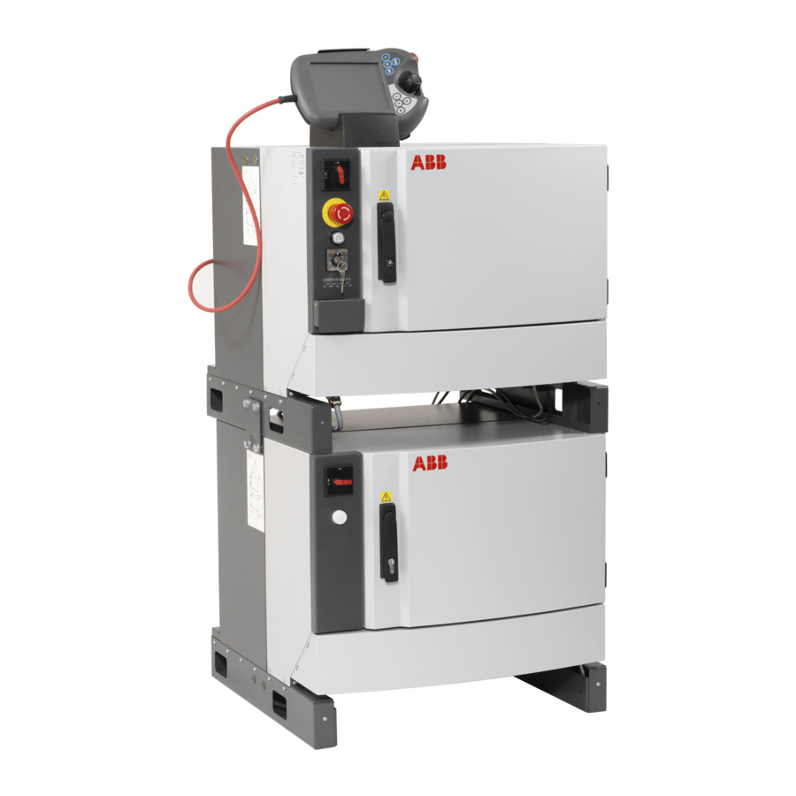
2.9.12 Installation of additional Drive Module General To be able to use a MultiMove system or to control more than 3 additional axes, an additional Drive Module is needed. The IRC5 Controller is prepared for up to three additional Drive Modules. xx0400001042 For more information about installing additional Drive Modules, see Application manual - MultiMove. -
Page 173: Process Module
Option numbers Product Option number Process module, Small 768-1 Process module, Large 768-2 Installation kit 715-1 Measurements Small process module xx1500000116 Continues on next page Product manual - IRC5 3HAC047136-001 Revision: M © Copyright 2004-2018 ABB. All rights reserved. - Page 174 The installation kit can be used for both the small and the large process module. It consists of the following parts. xx1500000118 Continues on next page Product manual - IRC5 3HAC047136-001 Revision: M © Copyright 2004-2018 ABB. All rights reserved.
- Page 175 Connection block bracket Holder for cables (2 pcs) Example of process module interior xx1500000115 Mounting beam Mounting bracket Connection block bracket Mounting bracket, short I/O mounting plate Product manual - IRC5 3HAC047136-001 Revision: M © Copyright 2004-2018 ABB. All rights reserved.
-
Page 176: Installation Of Drive System Fans With Temperature Sensors
3HAC056513-004, four fans • Temp sensor with sensor bracket • Gasket (4 pcs) Standard toolkit The contents are defined in section Standard toolkit. Continues on next page Product manual - IRC5 3HAC047136-001 Revision: M © Copyright 2004-2018 ABB. All rights reserved. - Page 177 C Attachment screws (4 pcs) Remove the top cover. Disconnect the connector to the fan. Remove the screw (item B in image below). Continues on next page Product manual - IRC5 3HAC047136-001 Revision: M © Copyright 2004-2018 ABB. All rights reserved.
- Page 178 187. Loosen the four attachment screws to the cover. Remove the cover. Disconnect the connector to the fan. Continues on next page Product manual - IRC5 3HAC047136-001 Revision: M © Copyright 2004-2018 ABB. All rights reserved.
- Page 179 Fit the connector for fan power supply from above into the outer hole on the bracket of the fan holder. Continues on next page Product manual - IRC5 3HAC047136-001 Revision: M © Copyright 2004-2018 ABB. All rights reserved.
- Page 180 A Sensor on sensor holder B Sensor cable C Fan channel bracket Route the fan cable behind the fan channel bracket. Continues on next page Product manual - IRC5 3HAC047136-001 Revision: M © Copyright 2004-2018 ABB. All rights reserved.
- Page 181 Connect the connectors to the fan. Refit the cover and the attachment screws. Refit the moist dust filter magazine. (Op- tion) Product manual - IRC5 3HAC047136-001 Revision: M © Copyright 2004-2018 ABB. All rights reserved.
-
Page 182: Testing
Function tests When the installation is complete, perform the function tests in section Function tests on page 196 to verify that the safety features work properly. Product manual - IRC5 3HAC047136-001 Revision: M © Copyright 2004-2018 ABB. All rights reserved. -
Page 183: Maintenance
Function test of general stop on page 203 Superior stop (tested if used) Function test 12 months Function test of superior stop on page 204 Continues on next page Product manual - IRC5 3HAC047136-001 Revision: M © Copyright 2004-2018 ABB. All rights reserved. - Page 184 Function test after replacement of component In addition to performing the function tests according to the intervals, function tests should be performed after replacing a component in the controller. Product manual - IRC5 3HAC047136-001 Revision: M © Copyright 2004-2018 ABB. All rights reserved.
-
Page 185: Inspection Activities
Inspection The procedure below describes how to inspect the IRC5 controller. WARNING Please observe the following before commencing any repair work on the IRC5 controller, or units connected to the controller: • Switch off all electric power supplies with the power switch! •... - Page 186 • Turn the power supply back off. Replace any malfunctioning fans as described in Replacement of heat ex- change unit and fan on page 220. Product manual - IRC5 3HAC047136-001 Revision: M © Copyright 2004-2018 ABB. All rights reserved.
-
Page 187: Changing/Replacing Activities
Other tools and procedures may be required. These procedures include references to the See references to these procedures in the step- tools required. by-step instructions below. Continues on next page Product manual - IRC5 3HAC047136-001 Revision: M © Copyright 2004-2018 ABB. All rights reserved. - Page 188 Pull the moist dust filter magazine in the arrow direction and remove it. xx0700000132 Remove the old moist dust filter by releasing the lock shackle and lifting it. xx0200000003 Continues on next page Product manual - IRC5 3HAC047136-001 Revision: M © Copyright 2004-2018 ABB. All rights reserved.
- Page 189 Fit the moist dust filter magazine on the cabinet and push inwards. xx0700000134 Push the moist dust filter magazine downwards until it stops. xx0700000135 Product manual - IRC5 3HAC047136-001 Revision: M © Copyright 2004-2018 ABB. All rights reserved.
-
Page 190: Cleaning Activities
• Never use compressed air or spray with a high pressure cleaner. • Never leave the door open when cleaning the exterior. Product manual - IRC5 3HAC047136-001 Revision: M © Copyright 2004-2018 ABB. All rights reserved. -
Page 191: Cleaning Moist Dust Filter
Lying flat on a flat surface Note • Blow with compressed air in opposite Do not wring the filter out! direction of filter airflow. Continues on next page Product manual - IRC5 3HAC047136-001 Revision: M © Copyright 2004-2018 ABB. All rights reserved. - Page 192 3 Maintenance 3.4.2 Cleaning moist dust filter Continued Action Note/Illustration Refit the moist dust filter. Product manual - IRC5 3HAC047136-001 Revision: M © Copyright 2004-2018 ABB. All rights reserved.
-
Page 193: Cleaning The Flexpendant
This section details how to clean the touch screen. Action Info/Illustration Before cleaning the screen, tap Lock Screen on the ABB menu. en0400001221 Continues on next page Product manual - IRC5 3HAC047136-001 Revision: M © Copyright 2004-2018 ABB. All rights reserved. - Page 194 Do's and don'ts! The section below specifies some special considerations when cleaning the FlexPendant. Always! • use ESD Protection Continues on next page Product manual - IRC5 3HAC047136-001 Revision: M © Copyright 2004-2018 ABB. All rights reserved.
- Page 195 FlexPendant. • spray with a high pressure cleaner. • clean the device, operating panel and operating elements with compressed air, solvents, scouring agent or scrubbing sponges. Product manual - IRC5 3HAC047136-001 Revision: M © Copyright 2004-2018 ABB. All rights reserved.
-
Page 196: Function Tests
If the earth fault breaker did not release, the test failed and the root cause of the failure must be found. After the test, reset the earth fault breaker. Product manual - IRC5 3HAC047136-001 Revision: M © Copyright 2004-2018 ABB. All rights reserved. -
Page 197: Function Test Of Emergency Stop
After the test, release the emergency stop button and press the motors on button to reset the emergency stop state. Product manual - IRC5 3HAC047136-001 Revision: M © Copyright 2004-2018 ABB. All rights reserved. -
Page 198: Function Test Of Mode Switch
If the event message “10015 Manual mode selected” is not shown in the FlexPendant log, the test failed and the root cause of the failure must be found. Product manual - IRC5 3HAC047136-001 Revision: M © Copyright 2004-2018 ABB. All rights reserved. -
Page 199: Function Test Of Three-Position Enabling Device
"20224 Enabling device conflict" appears in the Flexpendant log, the test is failed and the root cause of the failure must be found. Product manual - IRC5 3HAC047136-001 Revision: M © Copyright 2004-2018 ABB. All rights reserved. -
Page 200: Function Test Of Motor Contactors K42 And K43
If the event message "20227 Motor contact- or conflict" appears in the FlexPendant log, the test is failed and the root cause of the failure must be found. Product manual - IRC5 3HAC047136-001 Revision: M © Copyright 2004-2018 ABB. All rights reserved. -
Page 201: Function Test Of Brake Contactor K44
If the event message "37101 Brake failure" appears in the FlexPendant log, the test is failed and the root cause of the failure must be found. Product manual - IRC5 3HAC047136-001 Revision: M © Copyright 2004-2018 ABB. All rights reserved. -
Page 202: Function Test Of Auto Stop
“20225 Auto stop conflict” ap- pears in the Flexpendant log, the test is failed and the root cause of the failure must be found. Product manual - IRC5 3HAC047136-001 Revision: M © Copyright 2004-2018 ABB. All rights reserved. -
Page 203: Function Test Of General Stop
“20226 General stop conflict” appears in the Flexpendant log, the test is failed and the root cause of the failure must be found. Product manual - IRC5 3HAC047136-001 Revision: M © Copyright 2004-2018 ABB. All rights reserved. -
Page 204: Function Test Of Superior Stop
“20220 Superior stop conflict” appears in the Flexpendant log, the test is failed and the root cause of the failure must be found. Product manual - IRC5 3HAC047136-001 Revision: M © Copyright 2004-2018 ABB. All rights reserved. -
Page 205: Function Test Of Limit Switch
Testing limit switches for a SafeMove system Perform validation of the function Safe Axis Speed. See Application manual - SafeMove1. If this test is passed the limit switch works as intended. Product manual - IRC5 3HAC047136-001 Revision: M © Copyright 2004-2018 ABB. All rights reserved. -
Page 206: Function Test Of Automatic Fuse F1
If the automatic fuse did not release, the test failed and the root cause of the failure must be found. After the test, reset the automatic fuse. Product manual - IRC5 3HAC047136-001 Revision: M © Copyright 2004-2018 ABB. All rights reserved. -
Page 207: Function Test Of Reduced Speed Control
To get accurate results, use sensors or I/O signals to measure the time. Product manual - IRC5 3HAC047136-001 Revision: M © Copyright 2004-2018 ABB. All rights reserved. - Page 208 This page is intentionally left blank...
-
Page 209: Repair
If the procedure in general is the same, it is mentioned in each procedure where the part is located in the IRC5 controller. If there are significant differences, both the IRC5 controller and the drive module configurations are shown. -
Page 210: Replacement Of Panel Board
These procedures include references to the See references to these procedures in the tools required. step-by-step instructions below. Circuit diagram Circuit diagrams on page 325. Continues on next page Product manual - IRC5 3HAC047136-001 Revision: M © Copyright 2004-2018 ABB. All rights reserved. - Page 211 Make a note of any connections. Remove the lower attachment screw, and remove the Panel Unit. xx0400000812 • A: fixed attachments • B: hole for attachment screw Continues on next page Product manual - IRC5 3HAC047136-001 Revision: M © Copyright 2004-2018 ABB. All rights reserved.
- Page 212 B: hole for attachment screw Reconnect all connectors. Perform the function tests in section Function tests on page 196 to verify that the safety features work properly. Product manual - IRC5 3HAC047136-001 Revision: M © Copyright 2004-2018 ABB. All rights reserved.
-
Page 213: Replacement Of Flange Disconnect
See refer- ences to the tools needed. ences to these procedures in the step-by-step instructions below. Circuit diagram Circuit diagrams on page 325. Continues on next page Product manual - IRC5 3HAC047136-001 Revision: M © Copyright 2004-2018 ABB. All rights reserved. - Page 214 • A: spring • B: link Remove the two lower attachment screws. xx0600003139 • A: attachment screws Continues on next page Product manual - IRC5 3HAC047136-001 Revision: M © Copyright 2004-2018 ABB. All rights reserved.
- Page 215 Refit the two lower attachment screws. Refit the link to the unit. Perform the function tests in section Function tests on page 196 to verify that the safety features work properly. Product manual - IRC5 3HAC047136-001 Revision: M © Copyright 2004-2018 ABB. All rights reserved.
-
Page 216: Replacement Of I/O Units And Gateways
These procedures include references to the See references to these procedures in the tools required. step-by-step instructions below. Circuit diagram Circuit diagrams on page 325. Continues on next page Product manual - IRC5 3HAC047136-001 Revision: M © Copyright 2004-2018 ABB. All rights reserved. - Page 217 Hook the unit back onto the mounting rail and snap it gently in position. Reconnect all connectors disconnected during removal. Perform the function tests in section Function tests on page 196 to verify that the safety features work properly. Product manual - IRC5 3HAC047136-001 Revision: M © Copyright 2004-2018 ABB. All rights reserved.
-
Page 218: Replacement Of Backup Energy Bank
4.5 Replacement of backup energy bank 4.5 Replacement of backup energy bank Location The illustration below shows the location of the backup energy bank in the IRC5 controller. The backup energy bank is located behind the main computer attachment plate. - Page 219 Refit the front with the Panel Board Unit. Perform the function tests in section Function tests on page 196 to verify that the safety features work properly. Product manual - IRC5 3HAC047136-001 Revision: M © Copyright 2004-2018 ABB. All rights reserved.
-
Page 220: Replacement Of Heat Exchange Unit And Fan
These procedures include references to the quired. See references to these procedures tools required. in the step-by-step instructions below. Circuit diagram Circuit diagrams on page 325. Continues on next page Product manual - IRC5 3HAC047136-001 Revision: M © Copyright 2004-2018 ABB. All rights reserved. - Page 221 Put the new fan in place, and push down. xx0500001954 • A: fan • B: screw Refit the screw (item B in image above). Reconnect the connector to fan. Continues on next page Product manual - IRC5 3HAC047136-001 Revision: M © Copyright 2004-2018 ABB. All rights reserved.
- Page 222 • A: attachment screw for heat exchange unit Continues on next page Product manual - IRC5 3HAC047136-001 Revision: M © Copyright 2004-2018 ABB. All rights reserved.
- Page 223 Refitting of heat ex- changer fan on page 221. Perform the function tests in section Function tests on page 196 to verify that the safety fea- tures work properly. Product manual - IRC5 3HAC047136-001 Revision: M © Copyright 2004-2018 ABB. All rights reserved.
-
Page 224: Replacement Of Computer Unit
These procedures include references to the See references to these procedures in the tools required. step-by-step instructions below. Circuit diagram Circuit diagrams on page 325. Continues on next page Product manual - IRC5 3HAC047136-001 Revision: M © Copyright 2004-2018 ABB. All rights reserved. - Page 225 The procedure below details how to remove the computer unit. Note If possible, do a backup of the system before removing the computer unit. For information on how to do a backup see Operating manual - IRC5 with FlexPendant. Action...
- Page 226 The procedure below describes how to refit the computer unit. Note After replacing the main computer, the RobotWare system can be reset. It is then necessary to restore a backup. For information on how to restore a backup see Operating manual - IRC5 with FlexPendant. Action Note/illustration DANGER...
- Page 227 Reconnect all connectors to the computer unit. Perform the function tests in section Function tests on page 196 to verify that the safety features work properly. Product manual - IRC5 3HAC047136-001 Revision: M © Copyright 2004-2018 ABB. All rights reserved.
-
Page 228: Replacement Of Pciexpress Boards In The Computer Unit
Application manual - Func- tional safety and SafeMove2. Standard toolkit The contents are described in sec- tion Standard toolkit, IRC5 on page 305. Continues on next page Product manual - IRC5 3HAC047136-001 Revision: M © Copyright 2004-2018 ABB. All rights reserved. - Page 229 ESD on page 34 Disconnect any cables to/from the PCIex- press board. Make a note of which cables are disconnec- ted. Continues on next page Product manual - IRC5 3HAC047136-001 Revision: M © Copyright 2004-2018 ABB. All rights reserved.
- Page 230 Before commencing any work inside the cabinet, please observe the safety inform- ation in section Make sure that the main power has been switched off on page Continues on next page Product manual - IRC5 3HAC047136-001 Revision: M © Copyright 2004-2018 ABB. All rights reserved.
- Page 231 Make sure the robot system is configured to support the installed PCIexpress board. Perform the function tests in section Function tests on page 196 to verify that the safety features work properly. Product manual - IRC5 3HAC047136-001 Revision: M © Copyright 2004-2018 ABB. All rights reserved.
-
Page 232: Replacement Of Expansion Board In The Computer Unit
Before commencing any work inside the cabinet, please observe the safety inform- ation in section Make sure that the main power has been switched off on page Continues on next page Product manual - IRC5 3HAC047136-001 Revision: M © Copyright 2004-2018 ABB. All rights reserved. - Page 233 Grip the expansion board and gently pull it straight out. CAUTION Always grip the expansion board around the edges to avoid damage to the board or its components. Continues on next page Product manual - IRC5 3HAC047136-001 Revision: M © Copyright 2004-2018 ABB. All rights reserved.
- Page 234 Reconnect any cable to the fieldbus ad- apter. Perform the function tests in section Function tests on page 196 to verify that the safety features work properly. Product manual - IRC5 3HAC047136-001 Revision: M © Copyright 2004-2018 ABB. All rights reserved.
-
Page 235: Replacement Of Fieldbus Adapter In The Computer Unit
- PROFIBUS Anybus Device AnybusCC PROFINET slave 3HAC031670-001 DSQC 688 fieldbus adapter PROFINET communication is de- scribed in Application manu- al - PROFINET Anybus Device Continues on next page Product manual - IRC5 3HAC047136-001 Revision: M © Copyright 2004-2018 ABB. All rights reserved. - Page 236 The unit is sensitive to ESD on page 34 Disconnect any cables to/from the fieldbus adapter. Continues on next page Product manual - IRC5 3HAC047136-001 Revision: M © Copyright 2004-2018 ABB. All rights reserved.
- Page 237 A Attachment screws (2 pcs) B Fastening mechanism Grip the loosened attachment screws and gently pull the fieldbus adapter straight out. xx1500001755 A Fieldbus adapter Continues on next page Product manual - IRC5 3HAC047136-001 Revision: M © Copyright 2004-2018 ABB. All rights reserved.
- Page 238 A Fieldbus adapter CAUTION Always grip the fieldbus adapter around the edges to avoid damage to the adapter or its components. Continues on next page Product manual - IRC5 3HAC047136-001 Revision: M © Copyright 2004-2018 ABB. All rights reserved.
- Page 239 Make sure the robot system is configured to reflect the fieldbus adapter installed. Perform the function tests in section Function tests on page 196 to verify that the safety features work properly. Product manual - IRC5 3HAC047136-001 Revision: M © Copyright 2004-2018 ABB. All rights reserved.
-
Page 240: Replacement Of Fan In Computer Unit
These procedures include references to the See references to these procedures in the tools required. step-by-step instructions below. Circuit diagram Circuit diagrams on page 325. Continues on next page Product manual - IRC5 3HAC047136-001 Revision: M © Copyright 2004-2018 ABB. All rights reserved. - Page 241 The fan cable must not be stretched. Remove the fan attachment screw. Remove the fan from the upper cover. xx1300000806 Continues on next page Product manual - IRC5 3HAC047136-001 Revision: M © Copyright 2004-2018 ABB. All rights reserved.
- Page 242 The fan cable must not be squeezed. Perform the function tests in section Function tests on page 196 to verify that the safety features work properly. Product manual - IRC5 3HAC047136-001 Revision: M © Copyright 2004-2018 ABB. All rights reserved.
-
Page 243: Replacement Of Sd-Card Memory In Computer Unit
Slot for SD-card memory SD-card memory Note Only use SD-card memory supplied by ABB. Note The SD-card from the computer unit DSQC1018 cannot be used in the computer unit DSQC1024. Use the backup and restore function to move data from DSQC1018 to DSQC1024. - Page 244 Make sure that the SD-card memory is correctly oriented before inserting it. Otherwise the SD-card memory or the SD-card memory slot may be damaged. Continues on next page Product manual - IRC5 3HAC047136-001 Revision: M © Copyright 2004-2018 ABB. All rights reserved.
- Page 245 Gently push the SD-card memory with your finger until it clicks into place. Perform the function tests in section Function tests on page 196 to verify that the safety features work properly. Product manual - IRC5 3HAC047136-001 Revision: M © Copyright 2004-2018 ABB. All rights reserved.
-
Page 246: Replacement Of Drive Units
These procedures include references to See references to these procedures in the step- the tools required. by-step instructions below. Circuit diagram Circuit diagrams on page 325. Continues on next page Product manual - IRC5 3HAC047136-001 Revision: M © Copyright 2004-2018 ABB. All rights reserved. - Page 247 • A: Main Drive Unit • B: Attachment screws for MDU • C: Additional Drive Unit • D: Attachment screws for ADU Continues on next page Product manual - IRC5 3HAC047136-001 Revision: M © Copyright 2004-2018 ABB. All rights reserved.
- Page 248 Perform the function tests in section Function tests on page 196 to verify that the safety features work properly. Product manual - IRC5 3HAC047136-001 Revision: M © Copyright 2004-2018 ABB. All rights reserved.
-
Page 249: Replacement Of Axis Computer
The unit is sensitive to ESD on page 34 Disconnect all connectors from the axis com- puter. Make a note of the connections. Continues on next page Product manual - IRC5 3HAC047136-001 Revision: M © Copyright 2004-2018 ABB. All rights reserved. - Page 250 Refit the attachment screws. Reconnect all the connectors. Perform the function tests in section Function tests on page 196 to verify that the safety features work properly. Product manual - IRC5 3HAC047136-001 Revision: M © Copyright 2004-2018 ABB. All rights reserved.
-
Page 251: Replacement Of Eps Board Dsqc 646 For Electronic Position Switches
Before any work inside the cabinet, please observe the safety information in section Make sure that the main power has been switched off on page Continues on next page Product manual - IRC5 3HAC047136-001 Revision: M © Copyright 2004-2018 ABB. All rights reserved. - Page 252 • SMB cables • Ethernet cables xx0700000101 A: Plug contact in I/O connector B: Power cables C: SMB cables D: Ethernet cables Continues on next page Product manual - IRC5 3HAC047136-001 Revision: M © Copyright 2004-2018 ABB. All rights reserved.
- Page 253 Before commencing any work inside the cabinet, please observe the safety informa- tion in section Make sure that the main power has been switched off on page Continues on next page Product manual - IRC5 3HAC047136-001 Revision: M © Copyright 2004-2018 ABB. All rights reserved.
- Page 254 - Electronic Position Switches. Perform the function tests in section Func- tion tests on page 196 to verify that the basic safety features (e.g. emergency stop) work properly. Product manual - IRC5 3HAC047136-001 Revision: M © Copyright 2004-2018 ABB. All rights reserved.
-
Page 255: Replacement Of Safemove Board Dsqc 647
Before commencing any work inside the cabinet, please observe the safety inform- ation in section Make sure that the main power has been switched off on page Continues on next page Product manual - IRC5 3HAC047136-001 Revision: M © Copyright 2004-2018 ABB. All rights reserved. - Page 256 Remove the attachment screws of the SafeMove board and remove the SafeMove board. xx0800000104 • A: SafeMove board • B: attachment screws (4 pcs) Continues on next page Product manual - IRC5 3HAC047136-001 Revision: M © Copyright 2004-2018 ABB. All rights reserved.
- Page 257 The unit is sensitive to ESD on page If not already in place, fit the EMC strips on the SafeMove board. xx0800000204 • A: EMC strips Continues on next page Product manual - IRC5 3HAC047136-001 Revision: M © Copyright 2004-2018 ABB. All rights reserved.
- Page 258 Application manual - SafeMove1. Perform the function tests in section Func- tion tests on page 196 to verify that the basic safety features (e.g. emergency stop) work properly. Product manual - IRC5 3HAC047136-001 Revision: M © Copyright 2004-2018 ABB. All rights reserved.
-
Page 259: Replacement Of Safety Module Dsqc1015 For Safemove
Before commencing any work inside the cabinet, please observe the safety inform- ation in section Make sure that the main power has been switched off on page Continues on next page Product manual - IRC5 3HAC047136-001 Revision: M © Copyright 2004-2018 ABB. All rights reserved. - Page 260 Before commencing any work inside the cabinet, please observe the safety inform- ation in section Make sure that the main power has been switched off on page Continues on next page Product manual - IRC5 3HAC047136-001 Revision: M © Copyright 2004-2018 ABB. All rights reserved.
- Page 261 Perform a Cyclic Brake Check. See Application manual - Functional safety and SafeMove2. Lock the SafeMove configuration file. See Application manual - Functional safety and SafeMove2. Product manual - IRC5 3HAC047136-001 Revision: M © Copyright 2004-2018 ABB. All rights reserved.
-
Page 262: Replacement Of Remote Service Box
Other tools and procedures may be required. See references to these procedures in the step-by-step instructions below. Circuit diagram Circuit diagrams on page 325. Continues on next page Product manual - IRC5 3HAC047136-001 Revision: M © Copyright 2004-2018 ABB. All rights reserved. - Page 263 The unit is sensitive to ESD. Before handling the unit please observe the safety information in section The unit is sensitive to ESD on page Continues on next page Product manual - IRC5 3HAC047136-001 Revision: M © Copyright 2004-2018 ABB. All rights reserved.
- Page 264 Reconnect all connectors to the Remote Ser- vice box. Perform the function tests in section Function tests on page 196 to verify that the safety fea- tures work properly. Product manual - IRC5 3HAC047136-001 Revision: M © Copyright 2004-2018 ABB. All rights reserved.
-
Page 265: Replacement Of Contactor Interface Board
These procedures include references references to these procedures in the step-by-step to the tools required. instructions below. Circuit diagram Circuit diagrams on page 325. Continues on next page Product manual - IRC5 3HAC047136-001 Revision: M © Copyright 2004-2018 ABB. All rights reserved. - Page 266 4, must be moved to the new contactor inter- face board. Use a small flat pliers to remove the plugs. xx0800000035 • A: plug (2 pcs) Continues on next page Product manual - IRC5 3HAC047136-001 Revision: M © Copyright 2004-2018 ABB. All rights reserved.
- Page 267 Refit the attachment screws. Reconnect all connectors. Perform the function tests in section Func- tion tests on page 196 to verify that the safety features work properly. Product manual - IRC5 3HAC047136-001 Revision: M © Copyright 2004-2018 ABB. All rights reserved.
-
Page 268: Replacement Of Drive System Fans
These procedures include references to the quired. see references to these procedures tools required. in the step-by-step instructions below. Circuit diagram Circuit diagrams on page 325. Continues on next page Product manual - IRC5 3HAC047136-001 Revision: M © Copyright 2004-2018 ABB. All rights reserved. - Page 269 Before commencing any work inside the cabinet, please observe the safety inform- ation in section Make sure that the main power has been switched off on page Continues on next page Product manual - IRC5 3HAC047136-001 Revision: M © Copyright 2004-2018 ABB. All rights reserved.
- Page 270 Refit the moist dust filter magazine. (Op- tion) Perform the function tests in section Function tests on page 196 to verify that the safety features work properly. Product manual - IRC5 3HAC047136-001 Revision: M © Copyright 2004-2018 ABB. All rights reserved.
-
Page 271: Replacement Of Sensors For The Drive System Fans
These procedures include references to the quired. See references to these procedures tools required. in the step-by-step instructions below. Circuit diagram Circuit diagrams on page 325. Continues on next page Product manual - IRC5 3HAC047136-001 Revision: M © Copyright 2004-2018 ABB. All rights reserved. - Page 272 Slide the cable gland out of the indentation. xx1500000856 A Fan B Latches C Grooves D Temp sensor cable E Cable gland Push the fan upwards and remove it. Continues on next page Product manual - IRC5 3HAC047136-001 Revision: M © Copyright 2004-2018 ABB. All rights reserved.
- Page 273 A Sensor on sensor holder B Sensor cable C Fan channel bracket Route the fan cable behind the fan channel bracket. Continues on next page Product manual - IRC5 3HAC047136-001 Revision: M © Copyright 2004-2018 ABB. All rights reserved.
- Page 274 Refit the moist dust filter magazine. (Op- tion) Perform the function tests in section Function tests on page 196 to verify that the safety features work properly. Product manual - IRC5 3HAC047136-001 Revision: M © Copyright 2004-2018 ABB. All rights reserved.
-
Page 275: Replacement Of Transformer Unit
Before commencing any work inside the cabin- et, please observe the safety information in section Make sure that the main power has been switched off on page Continues on next page Product manual - IRC5 3HAC047136-001 Revision: M © Copyright 2004-2018 ABB. All rights reserved. - Page 276 This will facilitate reconnection to the same terminal. Remove the two transformer attachment screws. xx0500002032 • A: attachment screw (2pcs) Continues on next page Product manual - IRC5 3HAC047136-001 Revision: M © Copyright 2004-2018 ABB. All rights reserved.
- Page 277 Refit the moist dust filter magazine. (Option) Perform the function tests in section Function tests on page 196 to verify that the safety features work properly. Product manual - IRC5 3HAC047136-001 Revision: M © Copyright 2004-2018 ABB. All rights reserved.
-
Page 278: Replacement Of Brake Resistor Bleeder
These procedures include references to the See references to these procedures in the tools required. step-by-step instructions below. Circuit diagram Circuit diagrams on page 325. Continues on next page Product manual - IRC5 3HAC047136-001 Revision: M © Copyright 2004-2018 ABB. All rights reserved. - Page 279 This will result in too high temperature in the controller cabinet and shorter life time for the components. Continues on next page Product manual - IRC5 3HAC047136-001 Revision: M © Copyright 2004-2018 ABB. All rights reserved.
- Page 280 Lift the bleeder slightly and push it in to release the attachments. Lift the bleeder straight up. If the IRC5 controller uses an Additional Rectifier Unit, an extra ARU bleeder is mounted on the MDU bleeder. Remove the attachment screws and re- move the ARU bleeder from the MDU bleeder.
- Page 281 Make sure that the main power has been switched off on page If the IRC5 controller uses an Additional Rectifier Unit, an extra ARU bleeder is required. Attach the mounting brackets for ARU bleeder on the MDU bleeder.
- Page 282 Refit the moist dust filter magazine. (Op- tion) Perform the function tests in section Function tests on page 196 to verify that the safety features work properly. Product manual - IRC5 3HAC047136-001 Revision: M © Copyright 2004-2018 ABB. All rights reserved.
-
Page 283: Replacement Of Process Interface Board
Before commencing any work inside the cabinet, please observe the safety information in section Make sure that the main power has been switched off on page Continues on next page Product manual - IRC5 3HAC047136-001 Revision: M © Copyright 2004-2018 ABB. All rights reserved. - Page 284 Connect all connectors to the Process Interface Board. Perform the function tests in section Function tests on page 196 to verify that the safety features work properly. Product manual - IRC5 3HAC047136-001 Revision: M © Copyright 2004-2018 ABB. All rights reserved.
-
Page 285: Replacement Of Ethernet Switch
The unit is sensitive to ESD on page 34 Disconnect all connectors from the switch. Pull the spring lock to remove the switch. Continues on next page Product manual - IRC5 3HAC047136-001 Revision: M © Copyright 2004-2018 ABB. All rights reserved. - Page 286 Pull the spring lock and attach the switch to the mounting bar. Connect all connectors to the switch. Perform the function tests in section Function tests on page 196 to verify that the safety features work properly. Product manual - IRC5 3HAC047136-001 Revision: M © Copyright 2004-2018 ABB. All rights reserved.
-
Page 287: Replacement Of Power Supply
Risk of burns. Be careful when removing the unit. Do not route or place cables on top of the power distribution unit. Continues on next page Product manual - IRC5 3HAC047136-001 Revision: M © Copyright 2004-2018 ABB. All rights reserved. - Page 288 • A: left attachment screw • B: right attachment screw Remove the power distribution unit. Continues on next page Product manual - IRC5 3HAC047136-001 Revision: M © Copyright 2004-2018 ABB. All rights reserved.
- Page 289 Do not route or place cables on top of the power distribution unit. Perform the function tests in section Function tests on page 196 to verify that the safety features work properly. Product manual - IRC5 3HAC047136-001 Revision: M © Copyright 2004-2018 ABB. All rights reserved.
-
Page 290: Replacement Of Customer I/O Power Supply
To avoid damaging the Customer I/O power supply units, the units must be separated with 3 pcs of exterior support. Required equipment Equipment Article number Note Customer I/O power supply 3HAC14178-1 DSQC 609 Continues on next page Product manual - IRC5 3HAC047136-001 Revision: M © Copyright 2004-2018 ABB. All rights reserved. - Page 291 A: DIN-lock fixing screw • B: DIN-lock lever Pull the DIN-lock lever downwards to release the power supply unit. Remove the power supply unit. Continues on next page Product manual - IRC5 3HAC047136-001 Revision: M © Copyright 2004-2018 ABB. All rights reserved.
- Page 292 Refit the Flange disconnect unit (option). Perform the function tests in section Function tests on page 196 to verify that the safety features work properly. Product manual - IRC5 3HAC047136-001 Revision: M © Copyright 2004-2018 ABB. All rights reserved.
-
Page 293: Replacement Of System Power Supply
Other tools and procedures may be required. See refer- ences to these procedures in the step-by-step instructions below. Circuit diagram Circuit diagrams on page 325. Continues on next page Product manual - IRC5 3HAC047136-001 Revision: M © Copyright 2004-2018 ABB. All rights reserved. - Page 294 Before commencing any work inside the cabinet, please observe the safety information in section Make sure that the main power has been switched off on page Continues on next page Product manual - IRC5 3HAC047136-001 Revision: M © Copyright 2004-2018 ABB. All rights reserved.
- Page 295 Tighten the attachment screws (4 pcs). Reconnect all connectors to the unit. Perform the function tests in section Function tests on page 196 to verify that the safety features work properly. Product manual - IRC5 3HAC047136-001 Revision: M © Copyright 2004-2018 ABB. All rights reserved.
- Page 296 This page is intentionally left blank...
-
Page 297: Decommissioning
To remove all data from the SD card, use the Clean Disk function (part of Recovery Disk function) in RobotStudio. See Operating manual - RobotStudio. Product manual - IRC5 3HAC047136-001 Revision: M © Copyright 2004-2018 ABB. All rights reserved. -
Page 298: Environmental Information
Cables Steel Cabinet structure, plates, screws, etc. Plastic/rubber Cables, connectors, etc. Aluminium Heat sinks on power supplies and drive units Lead Electronics Brominated flame retardants Electronics Product manual - IRC5 3HAC047136-001 Revision: M © Copyright 2004-2018 ABB. All rights reserved. -
Page 299: Reference Information
6 Reference information 6.1 Introduction 6 Reference information 6.1 Introduction General This chapter includes general information, complementing the more specific information in the different procedures in the manual. Product manual - IRC5 3HAC047136-001 Revision: M © Copyright 2004-2018 ABB. All rights reserved. -
Page 300: Applicable Standards
Terminology and general principles EN 574:1996 + A1:2008 Safety of machinery - Two-hand control devices - Functional aspects - Principles for design Continues on next page Product manual - IRC5 3HAC047136-001 Revision: M © Copyright 2004-2018 ABB. All rights reserved. - Page 301 Safety requirements for industrial robots and robot systems ANSI/UL 1740 Safety standard for robots and robotic equipment CAN/CSA Z 434-14 Industrial robots and robot Systems - General safety require- ments Product manual - IRC5 3HAC047136-001 Revision: M © Copyright 2004-2018 ABB. All rights reserved.
-
Page 302: Unit Conversion
1 kg 2.21 lb. Weight 0.035 ounces Pressure 1 bar 100 kPa 14.5 psi Force 0.225 lbf Moment 1 Nm 0.738 lbf-ft Volume 0.264 US gal Product manual - IRC5 3HAC047136-001 Revision: M © Copyright 2004-2018 ABB. All rights reserved. -
Page 303: Screw Joints
The table below specifies the recommended standard tightening torque for oil-lubricated screws with slotted or cross-recess heads. Dimension Tightening torque (Nm) Class 4.8, oil-lubricated M2.5 0.25 Product manual - IRC5 3HAC047136-001 Revision: M © Copyright 2004-2018 ABB. All rights reserved. -
Page 304: Weight Specifications
In all repair and maintenance instructions, weights of the components handled are sometimes specified. All components exceeding 22 kg (50 lbs) are high-lighted in this way. To avoid injury, ABB recommends the use of lifting equipment when handling components with a weight exceeding 22 kg. Example... -
Page 305: Standard Toolkit, Irc5
Tx25 Screw driver, flat blade 4 mm Screw driver, flat blade 8 mm Screw driver, flat blade 12 mm Screw driver Phillips-1 Box spanner 8 mm Product manual - IRC5 3HAC047136-001 Revision: M © Copyright 2004-2018 ABB. All rights reserved. -
Page 306: Lifting Accessories And Lifting Instructions
This implies that the instructions delivered with the lifting accessories should be stored for later reference. Product manual - IRC5 3HAC047136-001 Revision: M © Copyright 2004-2018 ABB. All rights reserved. -
Page 307: Spare Parts
3HAC029818-001 Main Drive Unit, MDU-790A (large robots) DSQC 663 3HAC035381-001 Additional Rectifier Unit, ARU-430A (small DSQC 417 robots with additional drive unit) Continues on next page Product manual - IRC5 3HAC047136-001 Revision: M © Copyright 2004-2018 ABB. All rights reserved. - Page 308 1SFA611102R1105 Actuator white 1SFA611605R1201 Contact block 3HAC17317-3 LED lamp 3HNE 01586-1 Conveyor Tracking Unit DSQC 377B 3HNA027579-001 CTM-01 Conveyor Tracking Module DSQC2000 Continues on next page Product manual - IRC5 3HAC047136-001 Revision: M © Copyright 2004-2018 ABB. All rights reserved.
- Page 309 Spare part no. Description Type 3HAC025784-001 ADCombi I/O unit DSQC 651 3HAC025917-001 Digital I/O unit DSQC 652 3HNA006144-001 Process Interface Board Continues on next page Product manual - IRC5 3HAC047136-001 Revision: M © Copyright 2004-2018 ABB. All rights reserved.
- Page 310 Additional parts Spare part no. Description 3HAC060919-001 Connectors digital base/add-on 3HAC060925-001 Connectors analog add-on 3HAC060926-001 Connectors relay add-on 3HAC062073-001 DIN bracket Continues on next page Product manual - IRC5 3HAC047136-001 Revision: M © Copyright 2004-2018 ABB. All rights reserved.
- Page 311 3HAC045973-001 DeviceNet Slave Fieldbus Adapter DSQC1004 3HAC043383-001 DeviceNet Master/Slave PCIexpress DSQC1006 3HAC044872-001 PROFIBUS-DP Master PCIexpress DSQC1005 3HAC026525-001 3HAC14944-1 RS-232/422 Converter DSQC 615 Continues on next page Product manual - IRC5 3HAC047136-001 Revision: M © Copyright 2004-2018 ABB. All rights reserved.
- Page 312 Part of option 1170-1 3HAC054852-001 Temp sensor with sensor bracket for Part of option sensor controlled fan 1170-1 3HAC027697-001 Moist dust filter Option 3HAC027641-001 Moist dust filter Option Product manual - IRC5 3HAC047136-001 Revision: M © Copyright 2004-2018 ABB. All rights reserved.
-
Page 313: Flexpendant Parts
3HAC055665-004 FlexPendant extension cable 30 m 3HAC033498-001 FlexPendant holder 3HAC033596-002 FlexPendant holder upper part Cannot be used together with external operator's panel (option 733-3 or 733-4). Product manual - IRC5 3HAC047136-001 Revision: M © Copyright 2004-2018 ABB. All rights reserved. -
Page 314: Manipulator Cables
Control cable power 30 m Standard: 210-5 and 287-4 3HAC9038-1 Control cable power 7 m Foundry: 210-2 and 287-3 Wash: 210-2 and 287-5 Continues on next page Product manual - IRC5 3HAC047136-001 Revision: M © Copyright 2004-2018 ABB. All rights reserved. - Page 315 Control cable, power and signal 15 m (435-80 or 435-81 or 435-82) 3HAC029903-004 Control cable, power and signal 22 m (435-80 or 435-81 or 435-82) Continues on next page Product manual - IRC5 3HAC047136-001 Revision: M © Copyright 2004-2018 ABB. All rights reserved.
- Page 316 (435-6 or 435-18 or 435-24 or 435-36) and 210-3 3HAC026787-003 Control cable power 22 m (435-6 or 435-18 or 435-24 or 435-36) and 210-4 Continues on next page Product manual - IRC5 3HAC047136-001 Revision: M © Copyright 2004-2018 ABB. All rights reserved.
- Page 317 Art. no. Description Option no. 3HAC026787-004 Control cable power 30 m (435-6 or 435-18 or 435-24 or 435-36) and 210-5 Note IRB 8700 requires two power cables. Product manual - IRC5 3HAC047136-001 Revision: M © Copyright 2004-2018 ABB. All rights reserved.
-
Page 318: Fan Cables
(87-1 or 88-1 or 89-1) and 210-5 3HAC022708-001 Harness - axis 1/2/3 cooling (87-1 or 88-1 or 89-1) and 274-1 or 274-2 or 274-3 or 274-4 Product manual - IRC5 3HAC047136-001 Revision: M © Copyright 2004-2018 ABB. All rights reserved. -
Page 319: Cp/Cs Harness
Connection of Ethernet, L=3m 859-9 3HAC055518-002 Connection of Ethernet, L=7m 859-1 3HAC055518-003 Connection of Ethernet, L=15m 859-2 3HAC055518-004 Connection of Ethernet, L=22m 859-3 3HAC055518-005 Connection of Ethernet, L=30m 859-4 Product manual - IRC5 3HAC047136-001 Revision: M © Copyright 2004-2018 ABB. All rights reserved. -
Page 320: Cables Customer Power/Customer Signal
Wash: 94-4, 16-1 and 287-5 Foundry Prime: 94-4, 16-1 and 287-6 The option number depends on the protection type of the manipulator. Continues on next page Product manual - IRC5 3HAC047136-001 Revision: M © Copyright 2004-2018 ABB. All rights reserved. - Page 321 Cable CP/CS 22 m 218-9 and 94-3 3HAC14860-4 Cable CP/CS 30 m 218-9 and 94-4 The option number depends on the protection type of the manipulator. Product manual - IRC5 3HAC047136-001 Revision: M © Copyright 2004-2018 ABB. All rights reserved.
-
Page 322: Other Customer Cables
671-2 and 673-1 3HAC024328-005 Cable EMP67 15 m 671-2 and 673-2 3HAC024330-001 Cable EMP12 10 m 671-1 and 673-1 3HAC024330-004 Cable EMP12 15 m 671-1 and 673-2 Product manual - IRC5 3HAC047136-001 Revision: M © Copyright 2004-2018 ABB. All rights reserved. -
Page 323: Additional Cables
Cable between control module and drive module: L=1.7 m 3HAC025600-005 Cable between control module and drive 761-1 module: L=4 m 3HAC025600-006 Cable between control module and drive 761-3 module: L=30 m Product manual - IRC5 3HAC047136-001 Revision: M © Copyright 2004-2018 ABB. All rights reserved. - Page 324 This page is intentionally left blank...
-
Page 325: Circuit Diagrams
Controllers Product Article numbers for circuit diagrams Circuit diagram - IRC5 3HAC024480-011 Circuit diagram - IRC5 Compact 3HAC049406-003 Circuit diagram - IRC5 Panel Mounted Con- 3HAC026871-020 troller Circuit diagram - Euromap 3HAC024120-004 Circuit diagram - Spot welding cabinet 3HAC057185-001 Robots... - Page 326 3HAC025744-001 3HAC029940-001 Circuit diagram - IRB 6700 3HAC043446-005 Circuit diagram - IRB 7600 3HAC13347-1 3HAC025744-001 Circuit diagram - Product.ProductName 3HAC050778-003 Circuit diagram - IRB 910SC 3HAC056159-002 Product manual - IRC5 3HAC047136-001 Revision: M © Copyright 2004-2018 ABB. All rights reserved.
-
Page 327: Index
77 drive system fan, repair, 268 drive system fan sensor, 176, 271 drive unit, 108, 246 key of the mode switch, 37 DSQC1015, 153, 259 labels Product manual - IRC5 3HAC047136-001 Revision: M © Copyright 2004-2018 ABB. All rights reserved. - Page 328 176, 271 region specific regulations, 17 three-position enabling device, 27, 199 replacing tightening torque, 303 contactor interface board, 265 transformer, 69 expansion board, 232 fieldbus adapter, 235 Product manual - IRC5 3HAC047136-001 Revision: M © Copyright 2004-2018 ABB. All rights reserved.
- Page 329 Index USB ports, 112 weight, 49 wrist strap, 45 validity and responsibility, 17 Product manual - IRC5 3HAC047136-001 Revision: M © Copyright 2004-2018 ABB. All rights reserved.
- Page 332 PuDong District SHANGHAI 201319, China Telephone: +86 21 6105 6666 ABB Inc. Robotics and Motion 1250 Brown Road Auburn Hills, MI 48326 Telephone: +1 248 391 9000 abb.com/robotics © Copyright 2004-2018 ABB. All rights reserved. Specifications subject to change without notice.
Need help?
Do you have a question about the IRC5 and is the answer not in the manual?
Questions and answers