ABB RELION REX640 Technical Manual
Protection and control
Hide thumbs
Also See for RELION REX640:
- Technical manual (1760 pages) ,
- Operation manual (164 pages) ,
- Engineering manual (156 pages)
Table of Contents
Advertisement
Quick Links
Advertisement
Table of Contents

Related Manuals for ABB RELION REX640


Summary of Contents for ABB RELION REX640
- Page 1 — ® RELION PROTECTION AND CONTROL REX640 Technical Manual...
- Page 3 Document ID: 1MRS759142 Issued: 2023-02-07 Revision: F © Copyright 2023 ABB. All rights reserved...
- Page 4 Copyright This document and parts thereof must not be reproduced or copied without written permission from ABB, and the contents thereof must not be imparted to a third party, nor used for any unauthorized purpose. The software or hardware described in this document is furnished under a license and may be used, copied, or disclosed only in accordance with the terms of such license.
- Page 5 Other than under explicit contractual commitments, in no event shall ABB be responsible or liable for any loss or damage resulting from the use of this manual or the application of the equipment.
- Page 6 Conformity This product complies with the directive of the Council of the European Communities on the approximation of the laws of the Member States relating to electromagnetic compatibility (EMC Directive 2014/30/EU) and concerning electrical equipment for use within specified voltage limits (Low-voltage directive 2014/35/EU).
-
Page 7: Table Of Contents
Contents Contents Introduction..................... 30 This manual............................30 Intended audience..........................30 Product documentation........................31 1.3.1 Product documentation set....................31 1.3.2 Document revision history....................31 1.3.3 Related documentation......................31 Symbols and conventions........................32 1.4.1 Symbols........................... 32 1.4.2 Document conventions......................32 1.4.3 Functions, codes and symbols................... 34 REX640 overview..................42 Overview.............................. - Page 8 Contents 3.1.8 HMI control settings......................60 3.1.9 IEC 103 Settings........................61 3.1.10 IEC 103 Monitored data......................63 3.1.11 IEC 101-104 General settings....................63 3.1.12 IEC 101-104 Secure settings....................64 3.1.13 IEC 101-104 Secure statistics thresholds settings............65 3.1.14 IEC 101-104 Monitored data....................66 3.1.15 IEC 101-104 Secure monitored data...................66 3.1.16 IEC 61850-8-1 MMS settings....................67...
- Page 9 Contents 3.4.1 Function block........................116 3.4.2 Functionality .........................117 Individual virtual LED control LED.....................117 3.5.1 Identification.........................117 3.5.2 Function block........................117 3.5.3 Functionality......................... 118 3.5.4 Signals............................121 3.5.5 Settings..........................121 3.5.6 Monitored data........................121 Time synchronization..........................122 3.6.1 Time master supervision GNRLLTMS................122 Generic protection control PROTECTION..................131 3.7.1 Function block........................
- Page 10 Contents 3.14 Binary outputs............................163 3.14.1 Power output contacts.......................163 3.14.2 Signal output contacts.......................166 3.15 RTD/mA inputs/mA outputs......................169 3.15.1 Function blocks........................169 3.15.2 Functionality.........................169 3.15.3 Operation principle......................170 3.15.4 Application..........................174 3.15.5 RTD/mA input/mA output connection................180 3.15.6 Signals........................... 185 3.15.7 Settings..........................186 3.15.8 Monitored data........................
- Page 11 Contents 3.19.15 Integer 32-bit switch selector SWITCHI32..............227 3.19.16 Integer 32-bit to boolean conversion T_I32_TO_B16............ 228 3.19.17 Boolean to integer 32-bit conversion T_B16_TO_I32............ 229 3.19.18 Integer 8-bit to integer 32-bit conversion T_I8_TO_I32..........230 3.20 Configurable logic blocks........................231 3.20.1 Minimum pulse timer......................231 3.20.2 Pulse timer, eight channels PTGAPC (ANSI 62PT)............
- Page 12 Contents 3.22.7 Real greater than or equal comparator GER..............305 3.22.8 Real less than or equal comparator LER.................306 3.22.9 Real maximum value selector MAX3R................307 3.22.10 Real minimum value selector MIN3R................308 3.22.11 Real switch selector SWITCHR..................309 3.22.12 Integer 32-bit switch selector SWITCHI32..............310 3.23 Factory settings restoration......................
- Page 13 Contents 4.1.2 Three-phase directional overcurrent protection DPHxPDOC (ANSI 67P/51P-1, 67P/51P-2)........................344 4.1.3 Three-phase voltage-dependent overcurrent protection PHPVOC (ANSI 51V)..369 4.1.4 Accidental energization protection GAEPVOC (ANSI 27/50)........378 4.1.5 Three-phase thermal protection for feeders, cables and distribution transformers T1PTTR (ANSI 49F)................383 4.1.6 Three-phase thermal overload protection, two time constants T2PTTR (ANSI 49T/G/C).........................
- Page 14 Contents 4.4.1 Negative-sequence overcurrent protection NSPTOC (ANSI 46M)......819 4.4.2 Directional negative-sequence overcurrent protection DNSPDOC (ANSI 67Q)..825 4.4.3 Phase discontinuity protection PDNSPTOC (ANSI 46PD)........... 832 4.4.4 Phase reversal protection PREVPTOC (ANSI 46R)............837 4.4.5 Negative-sequence overcurrent protection for machines MNSPTOC (ANSI 46M).841 Voltage protection..........................850 4.5.1 Three-phase overvoltage protection PHPTOV (ANSI 59)..........
- Page 15 Contents 4.10.2 Function block........................1093 4.10.3 Functionality........................1094 4.10.4 Analog input configuration.....................1094 4.10.5 Operation principle......................1095 4.10.6 Application......................... 1099 4.10.7 Signals..........................1102 4.10.8 STTPMSU Settings......................1103 4.10.9 STTPMSU Monitored data....................1104 4.10.10 Technical data ........................1105 4.10.11 Technical revision history....................1105 4.11 Multipurpose protection MAPGAPC (ANSI MAP).................1105 4.11.1 Identification........................
- Page 16 Contents 5.2.2 Function block........................1162 5.2.3 Functionality........................1162 5.2.4 Analog channel configuration..................1163 5.2.5 Operation principle......................1163 5.2.6 Application...........................1171 5.2.7 Signals..........................1172 5.2.8 CCBRBRF Settings......................1173 5.2.9 CCBRBRF Monitored data....................1174 5.2.10 Technical data ........................1174 5.2.11 Technical revision history....................1174 Master trip TRPPTRC (ANSI 94/86)....................1175 5.3.1 Identification........................
- Page 17 Contents 5.6.6 Application.......................... 1191 5.6.7 Signals..........................1192 5.6.8 ESMGAPC Settings......................1192 5.6.9 ESMGAPC Monitored data....................1192 5.6.10 Technical data ........................1193 5.6.11 Technical revision history....................1193 Fault locator SCEFRFLO (ANSI FLOC).................... 1193 5.7.1 Identification........................1193 5.7.2 Function block........................1193 5.7.3 Functionality........................1194 5.7.4 Analog channel configuration..................1194 5.7.5 Operation principle......................
- Page 18 Contents 5.10.4 Operation principle......................1237 5.10.5 Application......................... 1244 5.10.6 Signals..........................1248 5.10.7 DSOCPSCH Settings......................1250 5.10.8 DSOCPSCH Monitored data....................1250 5.10.9 Technical data........................1250 5.11 Communication logic for residual overcurrent RESCPSCH (ANSI 85 67G/N SCHLGC)..1251 5.11.1 Identification........................1251 5.11.2 Function block........................1251 5.11.3 Functionality........................
- Page 19 Contents 5.14.5 Operation principle......................1282 5.14.6 Application......................... 1284 5.14.7 Signals..........................1284 5.14.8 DPSRDIR Settings......................1284 5.14.9 DPSRDIR Monitored data....................1285 5.15 Neutral power directional element DNZSRDIR (ANSI 67N-TC)..........1285 5.15.1 Identification........................1285 5.15.2 Function block........................1286 5.15.3 Functionality........................1286 5.15.4 Analog channel configuration..................1286 5.15.5 Operation principle......................
- Page 20 Contents 6.2.7 Signals..........................1317 6.2.8 CCSPVC Settings........................1318 6.2.9 CCSPVC Monitored data....................1318 6.2.10 Technical data ........................1318 6.2.11 Technical revision history....................1318 Current transformer supervision for high-impedance protection scheme HZCCxSPVC (ANSI CCM_A, CCM_B, CCM_C)....................1319 6.3.1 Identification........................1319 6.3.2 Function block........................1319 6.3.3 Functionality........................
- Page 21 Contents 6.6.6 Signals..........................1340 6.6.7 MDSOPT Settings......................1341 6.6.8 MDSOPT Monitored data....................1342 6.6.9 Technical data ........................1342 Motor start counter MSCPMRI (ANSI 66)..................1342 6.7.1 Identification........................1342 6.7.2 Function block........................1342 6.7.3 Functionality........................1342 6.7.4 Operation principle......................1343 6.7.5 Application......................... 1344 6.7.6 Signals..........................1344 6.7.7 MSCPMRI Settings......................
- Page 22 Contents 7.1.7 Signals..........................1371 7.1.8 SSCBR Settings........................1373 7.1.9 SSCBR Monitored data..................... 1375 7.1.10 Technical data ........................1375 Motor controlled earthing switch and disconnector supervision ESDCSSWI (ANSI 29CM)1376 7.2.1 Identification........................1376 7.2.2 Function block........................1376 7.2.3 Functionality........................1376 7.2.4 Operation principle......................1376 7.2.5 Application......................... 1380 7.2.6 Signals..........................1380 7.2.7...
- Page 23 Contents 7.5.7 Signals..........................1420 7.5.8 Settings..........................1423 7.5.9 DGMGAPC Monitored data....................1430 7.5.10 Technical data........................1432 Measurement functions..............1433 Basic measurements........................1433 8.1.1 Functions..........................1433 8.1.2 Measurement functionality..................... 1433 8.1.3 Measurement function applications................1442 8.1.4 Three-phase current measurement CMMXU (ANSI IA, IB, IC)........1442 8.1.5 Three-phase voltage measurement VMMXU (ANSI VA, VB, VC).......
- Page 24 Contents 8.5.7 TPOSYLTC Settings......................1503 8.5.8 TPOSYLTC Monitored data....................1503 8.5.9 Technical data ........................1504 Control functions................1505 Circuit breaker control CBXCBR, Disconnector control DCXSWI and Earthing switch control ESXSWI (ANSI 52, 29DS, 29GS)..................1505 9.1.1 Identification........................1505 9.1.2 Function block........................1505 9.1.3 Functionality........................
- Page 25 Contents 9.4.8 Monitored data........................1542 Synchronism and energizing check SECRSYN (ANSI 25)............1543 9.5.1 Identification........................1543 9.5.2 Function block........................1543 9.5.3 Functionality........................1543 9.5.4 Analog channel configuration..................1544 9.5.5 Operation principle......................1545 9.5.6 Application..........................1552 9.5.7 Signals..........................1553 9.5.8 SECRSYN Settings......................1554 9.5.9 SECRSYN Monitored data....................1555 9.5.10 Technical data ........................
- Page 26 Contents 9.9.1 Identification........................1661 9.9.2 Function block........................1661 9.9.3 Functionality........................1662 9.9.4 Operation principle......................1664 9.9.5 Counters..........................1677 9.9.6 Application..........................1678 9.9.7 Signals..........................1689 9.9.8 DARREC Settings.......................1690 9.9.9 DARREC Monitored data....................1693 9.9.10 Technical data ........................1694 9.10 Tap changer control with voltage regulator OL5ATCC (ANSI 90V)..........1695 9.10.1 Identification........................1695 9.10.2...
- Page 27 Contents 9.12.8 HSABTC Settings....................... 1801 9.12.9 HSABTC Monitored data....................1803 9.12.10 Technical data........................1806 10 Power quality measurement functions..........1807 10.1 Current total demand, harmonic distortion, DC component (TDD, THD, DC) and individual harmonics CHMHAI (ANSI PQM ITHD,IDC)............1807 10.1.1 Identification........................1807 10.1.2 Function block........................
- Page 28 Contents 10.4.3 Functionality........................1848 10.4.4 Analog channel configuration..................1849 10.4.5 Operation principle......................1849 10.4.6 Application......................... 1854 10.4.7 Signals..........................1854 10.4.8 VSQVUB Settings.......................1855 10.4.9 VSQVUB Monitored data....................1856 10.4.10 Technical data ........................1857 General function block features............1858 11.1 Definite time characteristics......................1858 11.1.1 Definite time operation....................
- Page 29 Contents 14 Technical data..................1940 15 Protection relay and functionality tests.......... 1949 16 Applicable standards and regulations..........1953 Glossary....................1954 REX640 Technical Manual...
-
Page 30: Introduction
Introduction 1MRS759142 F Introduction This manual The technical manual contains application and functionality descriptions and lists function blocks, logic diagrams, input and output signals, setting parameters and technical data sorted per function. The manual can be used as a technical reference during the engineering phase, installation and commissioning phase, and during normal service. -
Page 31: Product Documentation
1MRS759142 F Introduction Product documentation 1.3.1 Product documentation set Quick installation guide Brochure Product guide Operation manual Installation manual Engineering manual Technical manual Application manual Communication protocol manual IEC 61850 engineering guide Cyber security deployment guideline Hardware modification instructions Modification sales guideline Figure 1: The intended use of documents during the product life cycle 1.3.2 Document revision history... -
Page 32: Related Documentation
IEC 61850 interface in REX640 IEC 61850 Ed2 Model Implementation Conformance State- 1MRS759028 ment (MICS) for REX640 www.abb.com/ Download the latest documents from the ABB Web site mediumvoltage Symbols and conventions 1.4.1 Symbols The electrical warning icon indicates the presence of a hazard which could result in electrical shock. - Page 33 1MRS759142 F Introduction • Abbreviations and acronyms are spelled out in the glossary. The glossary also contains definitions of important terms. • Menu paths are presented in bold. Select Main menu > Settings. • Parameter names are shown in italics. Operation setting The function can be enabled and disabled with the •...
-
Page 34: Functions, Codes And Symbols
Introduction 1MRS759142 F 1.4.3 Functions, codes and symbols Table 1: Functions included in the relay Function IEC 61850 IEC 60617 ANSI Protection Distance protection DSTPDIS Z< 21P,21N Local acceleration logic DSTPLAL 21LAL Scheme communication logic DSOCPSCH 85 21SCHLGC Current reversal and weak-end infeed logic CRWPSCH CLCRW 85 21CREV,WEI... - Page 35 1MRS759142 F Introduction Function IEC 61850 IEC 60617 ANSI Phase discontinuity protection PDNSPTOC I2/I1> 46PD Residual overvoltage protection ROVPTOV Uo> 59G/59N Three-phase undervoltage protection PHPTUV 3U< Three-phase overvoltage variation protection PHVPTOV 3Urms> 59.S1 Three-phase overvoltage protection PHPTOV 3U> Positive-sequence overvoltage protection PSPTOV U1>...
- Page 36 Introduction 1MRS759142 F Function IEC 61850 IEC 60617 ANSI Loss of phase, undercurrent PHPTUC 3I< Loss of load supervision LOFLPTUC 3I< Motor load jam protection JAMPTOC Ist> 50TDJAM Motor start-up supervision STTPMSU Is2t n< 49,66,48,50TDLR Motor start counter MSCPMRI n< Phase reversal protection PREVPTOC I2>>...
- Page 37 1MRS759142 F Introduction Function IEC 61850 IEC 60617 ANSI Disconnector position indication DCSXSWI I <-> O DC 29DS Earthing switch position indication ESSXSWI I <-> O ES 29GS Motor controlled earthing switch and disconnector supervision ESDCSSWI ESDCCM 29CM Emergency start-up ESMGAPC ESTART EST,62...
- Page 38 Introduction 1MRS759142 F Function IEC 61850 IEC 60617 ANSI Phase voltage measurement VPHMMXU Residual voltage measurement RESVMMXU VG/VN Sequence voltage measurement VSMSQI U1, U2, U0 V1, V2, V0 Three-phase power and energy measurement PEMMXU P, E P, E Load profile recorder LDPRLRC LOADPROF LOADPROF...
- Page 39 1MRS759142 F Introduction Function IEC 61850 IEC 60617 ANSI OR gate with twenty inputs OR20 OR20 OR20 AND gate with two inputs AND gate with six inputs AND6 AND6 AND6 AND gate with twenty inputs AND20 AND20 AND20 XOR gate with two inputs NOT gate Real maximum value selector MAX3R...
- Page 40 Introduction 1MRS759142 F Function IEC 61850 IEC 60617 ANSI Real equal comparator Real not equal comparator Real greater than or equal comparator Real less than or equal comparator Voltage switch VMSWI VSWI VSWI Current sum CMSUM CSUM CSUM Current switch CMSWI CMSWI CMSWI...
- Page 41 1MRS759142 F Introduction Function IEC 61850 IEC 60617 ANSI Switching device status decoder - OPEN position T_POS_OP T_POS_OP T_POS_OP Switching device status decoder - OK status T_POS_OK T_POS_OK T_POS_OK Controllable gate, 8 Channels GATEGAPC GATEGAPC GATEGAPC Security application GSAL GSAL GSAL Hotline tag HLTGAPC...
-
Page 42: Rex640 Overview
PCM600 and relay connectivity package version • Protection and Control IED Manager PCM600 Ver. 2.12 or later • REX640 Connectivity Package Ver. 1.3.0 or later www.abb.com/ Download connectivity packages from the ABB Web site mediumvoltage or directly with Update Manager in PCM600. Relay hardware The relay includes a Ready LED on the power supply module that indicates the relay's status. - Page 43 In case the relay and the HMI will be exposed to harsh environmental conditions; like high humidity, chemicals or other corrosive agents, we recommend using the conformal coated versions of both. Contact the nearest ABB sales representative for more information regarding the ordering data.
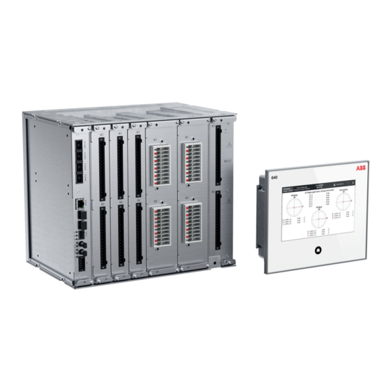
- Page 44 REX640 overview 1MRS759142 F Figure 2: Hardware module slot overview of the REX640 relay Slot markings in enclosure (top and bottom) Ready LED Table 3: Module description Module Description ARC1001 4 × ARC sensor inputs (lense, loop or mixed) COM1001 1 ×...
-
Page 45: Local Hmi
1MRS759142 F REX640 overview Module Description COM1005 1 × RJ-45 (LHMI port) + 2 × LC + 1 × LD-SFP + 1 × RS-485/IRIG-B + 1 × FO UART BIO1001/ 14 × BI + 8 × SO BIO1003 BIO1002/ 6 × SPO + 2 × SPO (TCS) + 9 × BI BIO1004 RTD1001 10 ×... - Page 46 REX640 overview 1MRS759142 F Figure 3: Example of a local HMI page The LHMI presents pages in two categories. • Operator pages are typically required as a part of an operator’s normal activities, such as a single-line diagram, controls, measurements, events or alarms •...
- Page 47 1MRS759142 F REX640 overview State Power supply LHMI Home Alarm module Ready button acknowledged Communication lost between Relay Steady green High frequency and LHMI, but no IRF blinking green LHMI not running normally or in Steady green High frequency start-up initialization phase blinking green Process related alarm active Steady green...
- Page 48 REX640 overview 1MRS759142 F Table 5: Local HMI default pages Page category Pages Subpages Operator pages Overview Alarms Events Fault Records Timeline Measurements Phasors Load Profile Records Engineer pages Parameters Testing and Commissioning Force Functions Force Outputs Simulate Inputs View I/O Send Events Secondary Injection Monitor- Protection Measurement Di-...
-
Page 49: Switchgear Hmi
1MRS759142 F REX640 overview Figure 5: Engineer pages menu Switchgear HMI The SHMI is used for setting, monitoring and controlling up to 20 REX640 protection relays and the related processes. It comprises a 7-inch color screen with capacitive touch sensing and a Home button at the bottom of the SHMI. All features of standard HMI are also available in the SHMI. - Page 50 REX640 overview 1MRS759142 F Figure 6: Example of a switchgear HMI navigation page The SHMI has a navigation page which presents the physical switchgear lineup installation and indicates the status of each REX640 within the system. The area presenting a single switchgear bay has a small user-configurable bay overview section and a virtual Home button showing the status of the connected relay.
-
Page 51: Bay Overview Area
1MRS759142 F REX640 overview Figure 7: Navigation page elements User-defined substation name User-defined name for the switchgear or sub-part of switchgear lineup controlled by the SHMI Date, time and time synchronization status Logout button and authentication status Menu button User-defined voltage level name User defined bay name and voltage level extension Bay overview area showing static or dynamic information for a bay and functioning as a navigation point to launch the HMI view for the respective... -
Page 52: Physical And Virtual Home Buttons
REX640 overview 1MRS759142 F 2.4.1 Bay overview area Bay overview area consists either of a static picture or a dynamic SLD. They are configured with Graphical Display Editor in PCM600. One relay can have two overview pages. Static picture may be, for example, a drawing or a photo of switchgear lineup. Maximum size of the picture is 186 ×... -
Page 53: Physical Ports
1MRS759142 F REX640 overview identifying which relay requires operator’s attention when the bay overview is not visible on the navigation page. When the HMI view is opened for a relay, the SHMI works exactly like a normal HMI. All the same features are available, and the Home button switches between the configured home pages and indicates the alarm status for the respective relay. -
Page 54: Web Hmi
REX640 overview 1MRS759142 F Web HMI The WHMI allows secure access to the protection relay via a Web browser. The WHMI is verified with Google Chrome, Mozilla Firefox and Microsoft Edge. Figure 9: Example view of the Web HMI WHMI offers several functions. The menu tree structure on the WHMI is almost identical to the one on the LHMI. -
Page 55: User Authorization
1MRS759142 F REX640 overview Main groups Submenus Description Parameters Used to view the menu tree structure for the protection relay's setting parameters Language selection Used to change the language Logout Used to end the session The WHMI can be accessed locally and remotely. •... -
Page 56: Station Communication
If it is needed to use the possibilities provided by the Modification Sales concept, please contact your local ABB unit. REX640 Technical Manual... -
Page 57: Basic Functions
1MRS759142 F Basic functions Basic functions General parameters 3.1.1 Authorization settings Table 7: Non group settings Parameter Values (Range) Unit Step Default Description Remote Update 0=Disable Remote update 0=Disable 1=Enable Thumbprint ClientThumb Print Remote override 1=True Disable authority 0=False 1=True Local override 1=True Disable authority... -
Page 58: Binary Input Settings
Basic functions 1MRS759142 F 3.1.2 Binary input settings Table 8: Binary input settings Parameter Values (Range) Unit Step Default Description Slot specific threshold 0=False 0=False Use slot specific binary input voltage threshold 1=True Slot specific hysteresis 0=False 0=False Use slot specific binary input voltage hysteresis 1=True Input threshold voltage... -
Page 59: System Settings
1MRS759142 F Basic functions Table 11: Non group settings Parameter Values (Range) Unit Step Default Description IP address 192.168.0.254 IP address for front port (fixed) Mac address XX-XX-XX-XX-XX-XX Mac address for front port 3.1.6 System settings Table 12: Non group settings Parameter Values (Range) Unit... -
Page 60: Hmi Control Settings
Basic functions 1MRS759142 F Table 13: Non group settings Parameter Values (Range) Unit Step Default Description FB naming conven- 1=IEC61850 FB naming conven- 1=IEC61850 tion tion used in IED 2=IEC60617 3=ANSI Backlight timeout 1...60 LHMI backlight timeout Web HMI mode 0=Off Web HMI function- 0=Off... -
Page 61: Iec 103 Settings
1MRS759142 F Basic functions Parameter Values Unit Step Default Description tors and earthing switches from HMI Close delay 5…900 Operation delay for Close delay mode Breaker oper- 0=After confir- Enable or disable 0=After confirmation ation mation confirmation dialog 1=Without confirma- before operating cir- tion cuit breakers, discon-... - Page 62 Basic functions 1MRS759142 F Parameter Values (Range) Unit Step Default Description 0=User frame 1=Standard frame 1 2=Standard frame 2 3=Standard frame 3 4=Standard frame 5=Standard frame 6=Private frame 6 7=Private frame 7 Frame3InUse -1=Not in use Active Class2 -1=Not in use Frame 3 0=User frame 1=Standard frame 1...
-
Page 63: Iec 103 Monitored Data
1MRS759142 F Basic functions Parameter Values (Range) Unit Step Default Description Block Monitoring 0=Not in use Blocking of Moni- 0=Not in use toring Direction 1=Discard events 2=Keep events EC_FRZ 0=False Control point for 0=False freezing energy 1=True counters Prtl Customization 0...2147483647 Customization pa- rameter. -
Page 64: Iec 101-104 Secure Settings
Basic functions 1MRS759142 F Parameter Values (Range) Unit Step Default Description Single Char Resp 0=False Single character 0=False response ena- 1=True bled/disabled Show Bad Time 1=True Enable/disable bad 0=False time quality indica- 1=True tion in events Time Format 1=Full 56bit Time stamp format 1=Full 56bit 3 or 7 octet... -
Page 65: Iec 101-104 Secure Statistics Thresholds Settings
1MRS759142 F Basic functions Table 18: Non group settings Parameter Values (Range) Unit Step Default Description Protocol Security 0=Off Protocol Security 1=App. authentica- Mode Mode - 0: Off; 1: tion Aplication authenti- 2=TLS and appl. cation; 2: TLS and auth. Aplication authenti- cation 0=Off... -
Page 66: Iec 101-104 Monitored Data
Basic functions 1MRS759142 F Parameter Values (Range) Unit Step Default Description Error Msgs Tx 1...65535 Security statistics threshold error messages sent Error Msgs Rx 1...65535 Security statistics threshold error messages received Successful Authn 1...65535 Security statistics threshold for suc- cessful authentica- tions Sesn key Chg 1...65535... -
Page 67: Iec 61850-8-1 Mms Settings
1MRS759142 F Basic functions Table 21: Monitored data Name Type Values (Range) Unit Description Unexp Msgs Cnt INT32 0...2147483646 Security statistics coun- ter for unexpected mes- sages Auth Fail Cnt INT32 0...2147483646 Security statistics coun- ter for authorization failures Authn Fail Cnt INT32 0...2147483646 Security statistics coun-... -
Page 68: Modbus Settings
Basic functions 1MRS759142 F Parameter Values (Range) Unit Step Default Description 1=On 1=On MMS communica- 0=Off tion mode 1=On 3.1.17 MODBUS Settings Table 23: Non group settings Parameter Values (Range) Unit Step Default Description Operation 5=off Enable or disable 1=on this protocol in- 5=off stance... - Page 69 1MRS759142 F Basic functions Parameter Values (Range) Unit Step Default Description Event ID selection 0=Address Selects whether the 0=Address events are reported 1=UID using the MB ad- dress or the UID number. Event buffering 0=Keep oldest Selects whether the 0=Keep oldest oldest or newest 1=Keep newest events are kept in...
-
Page 70: Modbus Monitored Data
Basic functions 1MRS759142 F 3.1.18 MODBUS Monitored data Table 24: Monitored data Name Type Values (Range) Unit Description Customization Mode Enum Protocol Customization 0=Off/Normal Mode 1=By Parameter 2=By File Reset counters BOOLEAN Reset counters 0=False 1=True Received frames INT32 -1...2147483646 Number of received frames Transmitted frames... - Page 71 1MRS759142 F Basic functions Parameter Values (Range) Unit Step Default Description UDP Tx Port 0...65535 UDP Destination Port for cli- ent/master Client control au- 2=All clients 0=no client con- 0=No clients thority trols allowed; 1=Reg. clients 1=Controls allowed by registered cli- 2=All clients ents;...
- Page 72 Basic functions 1MRS759142 F Parameter Values (Range) Unit Step Default Description UR Class 2 Min 0...999 Min number of events class 2 events to generate UR UR Class 2 TO 0...65535 Max holding time for class 2 events to generate UR UR Class 3 Min 0...999 Min number of...
-
Page 73: Dnp 3.0 Secure Settings
1MRS759142 F Basic functions Parameter Values (Range) Unit Step Default Description 6=16 bit frz counter 6=6:16bit FrzCnt event with time. evt&time Default Var Obj 30 5=5:AI float 1=32 bit AI; 2=16 bit 1=1:32bit AI AI; 3=32 bit AI with- 2=2:16bit AI out flag;... -
Page 74: Dnp 3.0 Secure Statistics Thresholds Settings
Basic functions 1MRS759142 F Parameter Values (Range) Unit Step Default Description Aplication authenti- 2=TLS and appl. cation auth. 0=Off Aggressive mode 1=Disable Aggressove mode - 1=Disable enable 1: disable; 2: enable 2=Enable Reply timeout 100...120000 2000 Reply timeout Exp Sesn key Chg 0...14400 1800 Expected Session... -
Page 75: Dnp 3.0 Monitored Data
1MRS759142 F Basic functions Parameter Values (Range) Unit Step Default Description Reply timeouts 1...65535 Security statistics threshold for reply timeouts Rekeys Authn fail- 1...65535 Security statistics threshold for re- keys due to authen- tication failure Total Msgs Tx 1...65535 Security statistics threshold for total messages sent Total Msgs Rx... -
Page 76: Dnp 3.0 Secure Monitored Data
Basic functions 1MRS759142 F 3.1.23 DNP 3.0 Secure monitored data Table 29: Monitored data Name Type Values (Range) Unit Description Unexp Msgs Cnt INT32 0...2147483646 Security statistics coun- ter for unexpected mes- sages Auth Fail Cnt INT32 0...2147483646 Security statistics coun- ter for authorization failures Authn Fail Cnt... -
Page 77: Com1 Monitored Data
1MRS759142 F Basic functions Parameter Values (Range) Unit Step Default Description 4=RS232 with hand- shake Baudrate 6=9600 Baudrate 1=300 2=600 3=1200 4=2400 5=4800 6=9600 7=19200 8=38400 9=57600 10=115200 3.1.25 COM1 Monitored data Table 31: Monitored data Name Type Values (Range) Unit Description Characters received... -
Page 78: Com2 Monitored Data
Basic functions 1MRS759142 F Parameter Values (Range) Unit Step Default Description 1=Fiber light ON loop 2=Fiber light OFF loop 3=Fiber light ON star 4=Fiber light OFF star Baudrate 6=9600 Baudrate 1=300 2=600 3=1200 4=2400 5=4800 6=9600 7=19200 8=38400 9=57600 10=115200 3.1.27 COM2 Monitored data Table 33: Monitored data... -
Page 79: Communication
1MRS759142 F Basic functions Parameter Values (Range) Unit Step Default Description 1=True Slot specific hyste- 0=False Use slot specific bi- 0=False resis nary input voltage 1=True hysteresis Input threshold 16...176 Global binary input voltage threshold for all slots Input threshold 10...50 Global binary input hysteresis... -
Page 80: Ethernet Addresses For Hmi
Basic functions 1MRS759142 F The LHMI has two RJ-45 connectors. One is for connecting the LHMI to the protection relay main unit and the second is a service port which is used for connecting the LHMI and a computer. This computer can be, for example, a laptop with the PCM600 engineering tool or a browser for WHMI. -
Page 81: Ethernet Redundancy
1MRS759142 F Basic functions 3.2.3 Ethernet redundancy IEC 61850 specifies a network redundancy scheme that improves the system availability for substation communication. It is based on two complementary protocols defined in the IEC 62439-3:2012 standard: parallel redundancy protocol PRP and high-availability seamless redundancy HSR protocol. Both protocols rely on the duplication of all transmitted information via two Ethernet ports for one logical network connection. - Page 82 Basic functions 1MRS759142 F LAN A LAN A LAN B LAN B Figure 10: Parallel redundancy protocol solution In case a laptop or a PC workstation is connected as a non-PRP node to one of the PRP networks, LAN A or LAN B, it is recommended to use a redundancy box device or an Ethernet switch with similar functionality between the PRP network and SAN to remove additional PRP information from the Ethernet frames.
-
Page 83: Process Bus
1MRS759142 F Basic functions Redundancy Redundancy Redundancy Redundancy Redundancy Redundancy Figure 11: High-availability seamless redundancy solution 3.2.3.1 Interlink port In the relay redundant COM module, the port without LAN-A/LAN-B tag is so called interlink-port. This port can be used to connect a device directly to the relay. Mainly this port should be used to connect a single point-to-point device, such as RIO600. - Page 84 Basic functions 1MRS759142 F over process bus brings also higher error detection because the signal transmission is automatically supervised. Additional contribution to the higher availability is the possibility to use redundant Ethernet network for transmitting SMV signals. Common Ethernet Station bus (IEC 61850-8-1), process bus (IEC 61850-9-2 LE) and IEEE 1588 v2 time synchronization Figure 12: Process bus application of voltage sharing and synchrocheck REX640 supports IEC 61850 process bus with sampled values of analog currents and voltages.
-
Page 85: Secure Communication
1MRS759142 F Basic functions Primary Secondary IEEE 1588 v2 IEEE 1588 v2 master clock master clock (optional) Managed HSR Managed HSR Ethernet Ethernet switch switch IEC 61850 Backup 1588 master clock Figure 13: Example network topology with process bus, redundancy and IEEE 1588 v2 time synchronization 3.2.5 Secure communication... - Page 86 Basic functions 1MRS759142 F Table 35: Secondary IP address parameters Parameter Options Description Configuration/Communication/Ether- False (default) Network 2 disabled net/Network 2 address/ Enable TRUE Network 2 enabled Configuration/Communication/Ether- 0.0.0.0 IP address for Net- net/Network 2 address/IP address work 2 Configuration/Communication/Ether- 0.0.0.0 Subnet address for net/Network 2 address/IP address...
- Page 87 1MRS759142 F Basic functions ARC1001 COM1002 COM1003 COM1001 Figure 14: Ethernet modes with Network 1 and Network 2 Network 1 Network 1 / Network 2 3.2.6.2 Protocol control It is possible to allow or block different protocols for different network interfaces in the protection relay using the parameters in Configuration >...
- Page 88 Basic functions 1MRS759142 F Table 36: Protocol control in the protection relay Parameter Options Description Configuration/Communication/Proto- Denies FTP and FTPS cols/Network1/FTP Allows FTP and FTPS Secure (Default) Allows FTPS only Configuration/Communication/Proto- Denies FTP and FTPS cols/Network2/FTP Allows FTP and FTPS Secure (Default) Allows FTPS only Configuration/Communication/Proto-...
-
Page 89: Serial Port Supervision Serlcch
1MRS759142 F Basic functions Table 37: Protocol write access in the protection relay Parameter Options Description Configuration/Authorization/Net- FTP write access denied for work1/FTP write access Network 1 On (Default) FTP write access allowed for Network 1 Configuration/Authorization/Net- IEC 61850 MMS write access work1/MMS write access denied for Network 1 On (Default) -
Page 90: Serial Port Supervision Serlcch
Basic functions 1MRS759142 F 3.2.7.1 Function block Figure 15: Function block 3.2.7.2 Functionality The function block represents the IEC61850 GOOSE communication monitoring and diagnostics in the relay. Function block includes the GOOSE diagnostic counters that can be accessed via HMI, and ALARM output. ALARM output indicates if overall GOOSE communication status is good or not. -
Page 91: Physical Locations Of The Serial Channels
1MRS759142 F Basic functions 3.2.9 Assigning of a serial communication protocol to a COM serial port The settings of the serial communication protocol instance include a setting Port or Serial port , which is used to select the COM1 or parameter, called either COM2 setting. - Page 92 Basic functions 1MRS759142 F Figure 17: X8 connector pinout for socket on communication board Table 39: LED configuration (COM1004...COM1005) Description X1 LANA X2 LANB X6 LD X7 TX FO-UART X8 TX RS-485/COM2 X8 TX RS-485/COM1 IRIG-B IRIG-B REX640 Technical Manual...
-
Page 93: Rs-485 Bias And Termination Settings
1MRS759142 F Basic functions 3.2.11 RS-485 bias and termination settings A 6 x DIP switch is located on the COM1004...COM1005 cards. The COM card Figure 18 needs to be pulled out from the relay case to access the switch. See for the location of the switch. -
Page 94: Serial Link Diagnostics And Monitoring
Basic functions 1MRS759142 F 3.2.12 Serial link diagnostics and monitoring Serial communication diagnostics and monitoring is divided between the serial link driver and the serial communication protocol. The lower-level physical and protocol- independent aspects of the UART-based serial communication are monitored in the serial link driver. -
Page 95: Modbus Protocol Mbslprt
1MRS759142 F Basic functions 3.2.13 Modbus protocol MBSLPRT 3.2.13.1 Function block MBSLPRT1 STATUS Figure 19: Function block 3.2.13.2 Functionality The function block represents a Modbus server protocol instance in the protection relay. Function block settings include communication interface assignment for the instance, that is, Ethernet/TCP or serial. -
Page 96: Iec 60870-5-103 Protocol I3Clprt
Basic functions 1MRS759142 F A DNP3 server protocol instance is activated if the function block instance is added Operation should be "On" and setting to the application configuration. The setting Port should have the communication interface assignment. The STATUS output of the function block is active if DNP3 client requests or DNP3 supervision messages have been received on the communication interface within an interval defined by the link keep-alive parameter. -
Page 97: Iec 60870-5-104 Protocol I5Clprt
1MRS759142 F Basic functions 3.2.16 IEC 60870-5-104 protocol I5CLPRT 3.2.16.1 Function block Figure 22: Function block 3.2.16.2 Functionality The function block represents one IEC 60870-5-104 TCP/IP server protocol instance in the protection relay. An IEC 60870-5-104 server protocol instance is activated if the function block Operation should instance is added to the application configuration. - Page 98 Basic functions 1MRS759142 F preventing the relay from making false decisions, such as issuing false control commands. There are two types of fault indications. • Internal faults • Warnings Warnings are indications of less severe situations which can also be caused by external reasons, for example, in case the RTD sensor measurement circuit is not complete.
-
Page 99: Internal Faults
3-5 opens. Figure 25: Output contact The internal fault code indicates the type of internal relay fault. When a fault appears, the code must be recorded so that it can be reported to ABB customer service. REX640... - Page 100 Basic functions 1MRS759142 F More details about the active internal fault are found on the Relay Status page. On the LHMI, the internal fault state is indicated with a red LED. More information about the fault and recovery options can be accessed by tapping More Information. Figure 26: Internal fault state indicated with red LED More Information shows all active faults and the corresponding fault codes.
- Page 101 Start up error: If relay SW has just been System error HW/SW mismatch updated, redo it. If not re- covered, contact your near- est ABB representative to check the next possible corrective action. Internal Fault Start up or runtime Yes (3) Restart the relay.
- Page 102 Basic functions 1MRS759142 F Slow 10min self- recovery Fast self- Fault Immediate Additional recovery (# of Action in permanent fault Fault indication code information attempt attempts) IRF-mode state ing, replace the relay, most probably hardware failure in CPU module. Internal Fault Start up error: Card Yes (3) Restart the relay.
- Page 103 1MRS759142 F Basic functions Slow 10min self- recovery Fast self- Fault Immediate Additional recovery (# of Action in permanent fault Fault indication code information attempt attempts) IRF-mode state Internal Fault Start up error: Er- Restart the relay. If recov- EEPROM error ror in the EEPROM ered by restarting, contin- memory on the...
- Page 104 Basic functions 1MRS759142 F Slow 10min self- recovery Fast self- Fault Immediate Additional recovery (# of Action in permanent fault Fault indication code information attempt attempts) IRF-mode state Internal Fault Runtime error: Yes (3) Check wirings. Restart the SO-relay(s), Slot Faulty Signal Out- relay.
- Page 105 1MRS759142 F Basic functions Slow 10min self- recovery Fast self- Fault Immediate Additional recovery (# of Action in permanent fault Fault indication code information attempt attempts) IRF-mode state Internal Fault Runtime error: Yes (3) Check wirings. Restart the PO-relay(s), Slot Faulty Power Out- relay.
- Page 106 Product license er- cation Sales has been car- cense error ror, license file is ried out, redo the update. If not found or is not recovered, contact your wrong nearest ABB representative to check the next possible corrective action. REX640 Technical Manual...
-
Page 107: Warnings
LHMI Home button flashes red. If a warning appears, record the name and code so that it can be provided to ABB customer service. See the operation manual for more information on reading internal log files from the relay. On the LHMI, an active warning is indicated with a yellow LED. More information about the warning and recovery options can be accessed by tapping More Information. - Page 108 Basic functions 1MRS759142 F Figure 30: More information about the warning The warning alarm is only displayed when configured in PCM600 event filtering. Table 44: Warning indications and codes Warning indication Warning code Additional information Watchdog reset A watchdog reset has occurred. Power down det.
-
Page 109: Power Supply Module Ready Led And Hmi Home Button Led
1MRS759142 F Basic functions Warning indication Warning code Additional information Comm. channel down Redundant Ethernet (HSR/ PRP) communication interrupted. Settings mismatch Mismatch between parameter set- tings and application configuration. Protection comm. Error in protection communication. ARC1 cont. light A continuous light has been detec- ted on the ARC light input 1. -
Page 110: Fail-Safe Principle For Relay Protection
Basic functions 1MRS759142 F State Power supply LHMI Home Alarm module Ready button acknowledged Process related alarm has been ac- Steady green Steady green tive earlier, but is not any more ac- tive Relay set to Test Mode LF blinking green LF blinking green No The physical SHMI Home button has two operation modes. - Page 111 1MRS759142 F Basic functions Control + AUX. POWER <U Control - Figure 31: Motor feeder fail-safe trip circuit principle, example 1 Protection relay Emergency stop Circuit breaker (CB) Protection relay trip output Internal relay fault indication <U CB undervoltage trip coil CB trip coil 1 Distributed process control system Miniature circuit breaker...
- Page 112 Basic functions 1MRS759142 F Protection relay trip output Internal relay fault indication <U CB undervoltage trip coil CB trip coil 1 Distributed process control system Miniature circuit breaker In example 2, the fail-safe approach aims at securing motor shutdown via an emergency switch and in case the control voltage disappears.
- Page 113 1MRS759142 F Basic functions Control + Control + +J01 +J02 +J02 -A1 +J01 -A1 +J02 -A1 +J01 -A1 <U <U Control - Control - Figure 34: Motor feeder fail-safe trip circuit principle, example 4 Feeder #1 panel Feeder #2 panel Emergency stop Circuit breaker Relay trip output #1...
- Page 114 Basic functions 1MRS759142 F Control + Control + +J01 +J0x Incomer protec on start + AUX. POWER AUX. POWER Incomer protec on start + Incomer protec on start - Incomer Control - Control - protec on start - Figure 35: Redundant protection fail-safe principle, example 1 Incomer feeder panel Load feeder panels Circuit breaker (CB)
- Page 115 1MRS759142 F Basic functions Feeder #1 panel Feeder #2 panel Circuit breaker (CB) Relay trip output #1 Relay trip output #2 Protection relay CB trip coil 1 CB trip coil 2 Miniature circuit breaker In example 2, the fail-safe approach aims at securing circuit breaker tripping even if a relay fails.
-
Page 116: Led Indication Control Ledptrc
Basic functions 1MRS759142 F have all the features of the main relay, mainly containing a minimum acceptable set of protection functions. Control + -TO1 -TO2 -TO2 Same principle as for TC1 AUX. POWER AUX. POWER AUX. POWER -TO1 -TO1 -TO2 Control - Figure 38: Redundant protection fail-safe principle, example 4 Circuit breaker (CB) -
Page 117: Function Block
1MRS759142 F Basic functions 3.4.1 Function block Figure 39: Function block 3.4.2 Functionality The protection relay includes a global conditioning function LEDPTRC that is used to control the virtual Start and Trip indication LEDs. LED indication control should never be used for tripping purposes. There is a separate trip logic function TRPPTRC available in the relay configuration. -
Page 118: Functionality
Basic functions 1MRS759142 F 3.5.2 Function block Figure 40: Function block 3.5.3 Functionality The virtual, programmable LEDs are visible on the Programmable LEDs page in LHMI and on the WHMI dashboard. Figure 41: Programmable LEDs page in LHMI REX640 Technical Manual... - Page 119 1MRS759142 F Basic functions Figure 42: Programmable LEDs status in WHMI Programmable LEDs are available only when at least one LED has been instantiated and the OK or ALARM signal is connected in Application Configuration in PCM600. All the programmable LEDs on the protection relay's HMI have two colors, green and red.
- Page 120 Basic functions 1MRS759142 F Alarm mode alternatives The ALARM input behavior can be selected with the alarm mode settings from the alternatives "Follow-S", "Follow-F", "Latched-S" and "LatchedAck-F-S". The OK input behavior is always according to "Follow-S". The alarm input latched modes can be cleared with the reset input in the application logic.
-
Page 121: Signals
1MRS759142 F Basic functions Activating signal Acknow. Figure 47: Operating sequence "LatchedAck-F-S" 3.5.4 Signals Table 46: Input signals for LEDs 1...66 Name Type Default Description BOOLEAN 0=False Ok input for the LED ALARM BOOLEAN 0=False Alarm input for the RESET BOOLEAN 0=False Reset input for the... -
Page 122: Time Synchronization
Basic functions 1MRS759142 F Table 49: IEC 61850 mapping LED instance in Application Mapping in IEC 61850 data model (ALARM and OK signals) Configuration LED1...LED11 LEDGGIO1.Alm1...LEDGGIO1.Alm11 LEDGGIO1.Ind1...LEDGGIO1.Ind11 LED12...LED22 LEDGGIO2.Alm1...LEDGGIO2.Alm11 LEDGGIO2.Ind1...LEDGGIO2.Ind11 LED23..LED33 LEDGGIO3.Alm1...LEDGGIO3.Alm11 LEDGGIO3.Ind1...LEDGGIO3.Ind11 LED34...LED44 LEDGGIO4.Alm1...LEDGGIO4.Alm11 LEDGGIO4.Ind1...LEDGGIO4.Ind11 LED45...LED55 LEDGGIO5.Alm1...LEDGGIO5.Alm11 LEDGGIO5.Ind1...LEDGGIO5.Ind11 LED56..LED66 LEDGGIO6.Alm1...LEDGGIO6.Alm11 LEDGGIO6.Ind1...LEDGGIO6.Ind11 Time synchronization... - Page 123 1MRS759142 F Basic functions Real-time clock at power off During power off, the system time is kept in a separate capacitor-backed RTC. This RTC provides a millisecond resolution and digital temperature compensation for the crystal oscillator. Typical accuracy is 5 ppm which means the time may drift maximum 0.5 seconds per day.
- Page 124 Basic functions 1MRS759142 F IP SNTP secondary as "0.0.0.0". If one SNTP server is used, it is recommended to set This disables the server redundancy scheme and prevents the IED from attempting to access a non-existing secondary server. The time is requested from the SNTP server every 60 seconds. Supported SNTP versions are 3 and 4.
- Page 125 1MRS759142 F Basic functions IRIG-B IRIG-B time synchronization requires IRIG-B format B00x and IRIG-B time code extensions according to IEEE Std C37.118.1TM-2011. The extensions are defined by Annex D. The synchronization time in IRIG-B can be either UTC time or local time. As no reboot is necessary, the time synchronization starts immediately after the IRIG- B synchronization source is selected and the IRIG-B signal source is connected.
- Page 126 Basic functions 1MRS759142 F Name Type Description FALSE if the clock has not been synchronized by an SNTP server. Table 52: IEEE 1588v2 Output signals Name Type Description ALARM BOOLEAN Alarm status for clock synchronization. TRUE if the current master’s accuracy is not within 1μs or priority1 is bigger than that of first secondary’s.
- Page 127 1MRS759142 F Basic functions Name Type Description FALSE if the clock has been synchronized by the master. WARNING BOOLEAN Warning status for clock synchronization. TRUE if the clock has not been synchronized by the master. FALSE if the clock has been synchronized by the master.
- Page 128 Basic functions 1MRS759142 F Time settings Table 57: Non group settings Parameter Values (Range) Unit Step Default Description Synch source 1=SNTP Time synchroniza- 0=None tion source 1=SNTP 2=Modbus 3=IEEE 1588 5=IRIG-B 9=DNP 17=IEC60870-5-103 PTP Profile 1=IEEE Profile Selection for 1=IEEE C37.238-2011 the Precision Time C37.238-2011...
- Page 129 1MRS759142 F Basic functions Table 60: Non group settings Parameter Values (Range) Unit Step Default Description DST in use 1=True DST in use setting 0=False 1=True DST on time 0...23 Daylight saving (hours) time on, time (hh) DST on time (mi- 0...59 Daylight saving nutes)
- Page 130 Basic functions 1MRS759142 F Parameter Values (Range) Unit Step Default Description 2=Tuesday 3=Wednesday 4=Thursday 5=Friday 6=Saturday 7=Sunday DST offset -720...720 Daylight saving time offset 3.6.1.5 Monitored data Table 61: Monitored data Name Type Values (Range) Unit Description Synch source Enum Time synchronization 0=Not defined source...
-
Page 131: Generic Protection Control Protection
1MRS759142 F Basic functions Name Type Values (Range) Unit Description 11=2.5 ms 12=10 ms 13=25 ms 14=100 ms 15=250 ms 16=1 s 17=10 s 18=more than 10 s Generic protection control PROTECTION 3.7.1 Function block Figure 49: Function block 3.7.2 Functionality 3.7.2.1 Setting group control... - Page 132 Basic functions 1MRS759142 F Table 62: Optional operation modes for setting group selection SG operation mode Description Operator (Default) Setting group can be changed with the setting Settings/Set- ting group/Active group. Value of the out- SG_LOGIC_SEL put is FALSE. Logic mode 1 Setting group can be changed with binary inputs ).
- Page 133 1MRS759142 F Basic functions 3.7.2.2 Test mode The function has two outputs, BEH_TST and BEH_BLK, which are activated in test Table 65 mode according to Table 65: Test mode Test mode Description Protection Protection BEH_BLK BEH_TST Normal mode Normal operation FALSE FALSE IED blocked...
-
Page 134: Signals
Basic functions 1MRS759142 F 3.7.2.4 Special function block outputs The function block has a few outputs dedicated for special purposes. Table 66: Special function block outputs Output Description CNF_CHANGE Any setting change in the protection relay activates this out- put for a short period of time (100...200 ms). GRPOFF Some application function blocks do now allow unconnected analog inputs. -
Page 135: Settings
1MRS759142 F Basic functions Name Type Description GRPOFF Group signal Group off signal for function blocks DEV_WARN BOOLEAN Protection relay internal warning FRQ_ADP_WARN BOOLEAN Frequency adaptivity warning FRQ_ADP_FAIL BOOLEAN Frequency adaptivity status fail FRQ_ADP_BU BOOLEAN Main frequency adaptivity source 3.7.4 Settings Table 69: PROTECTION Settings Parameter... -
Page 136: L/R Control Access
Basic functions 1MRS759142 F The actual state is reflected on the CONTROL function outputs. Only one output is active at a time. Table 70: Truth table for CONTROL Input Output CTRL_OFF CTRL_LOC CTRL_STA CTRL_REM CTRL_ALL TRUE OFF = TRUE FALSE TRUE LOCAL = TRUE... - Page 137 1MRS759142 F Basic functions REMOTE LOCAL IEC 61850 IEC 61850 IEC 61850 IEC 61850 IEC 61850 IEC 61850 remote remote remote remote remote remote Figure 51: Station authority is “L,R” When station authority level “L,R” is used, control access can be selected using R/L button or CONTROL function block.
-
Page 138: Station Authority Level "L,R,L+R
Basic functions 1MRS759142 F 3.8.5 Station authority level "L,R,L+R" Station authority level "L,R, L+R" adds multilevel access support. Control access can also be simultaneously permitted from local or remote location. Simultaneous local or remote control operation is not allowed as one client and location at time can access controllable objects and they remain reserved until the previously started control operation is first completed by the client. -
Page 139: Station Authority Level "L,S,R
1MRS759142 F Basic functions 3.8.6 Station authority level "L,S,R" Station authority level "L,S,R" adds station control access. In this level IEC 61850 command originator category validation is performed to distinguish control commands with IEC 61850 command originator category set to “Remote” or “Station”. -
Page 140: Station Authority Level "L,S,S+R,L+S,L+S+R
Basic functions 1MRS759142 F Table 76: Station authority level “L,S,R” using CONTROL function block L/R Control L/R Control status Control access R/L button CTRL.LLN0.LocS CTRL.LLN0.MltL L/R state Local user IEC 61850 client IEC 61850 CTRL.LLN0.Loc client KeyHMI CTRL_OFF FALSE FALSE CTRL_LOC FALSE FALSE... -
Page 141: Control Mode
1MRS759142 F Basic functions Table 77: Station authority level “L,S,S+R,L+S,L+S+R” using R/L button L/R Control L/R Control status Control access R/L button CTRL.LLN0.LocS CTRL.LLN0.MltL L/R state Local user IEC 61850 client IEC 61850 CTRL.LLN0.Loc client KeyHMI Local FALSE FALSE Remote FALSE TRUE Remote... -
Page 142: Signals
Basic functions 1MRS759142 F 3.8.9 Signals Table 80: CONTROL Input signals Name Type Default Description CTRL_OFF BOOLEAN Control input OFF CTRL_LOC BOOLEAN Control input Local CTRL_STA BOOLEAN Control input Station CTRL_REM BOOLEAN Control input Remote CTRL_ALL BOOLEAN Control input All Table 81: CONTROL Output signals Name Type... -
Page 143: Monitored Data
1MRS759142 F Basic functions 3.8.11 Monitored data Table 83: Monitored data Name Type Values (Range) Unit Description Command response Enum Latest command re- 0=No commands sponse 1=Select open 2=Select close 3=Operate open 4=Operate close 5=Direct open 6=Direct close 7=Cancel 8=Position reached 9=Position timeout 10=Object status only 11=Object direct... -
Page 144: Fault Recorder Fltrfrc (Ansi Fr)
Basic functions 1MRS759142 F Fault recorder FLTRFRC (ANSI FR) 3.9.1 Function block Figure 55: Function block 3.9.2 Functionality The protection relay has the capacity to store the records of the latest 128 fault events. Fault records include fundamental or RMS current values. The records enable the user to analyze recent power system events. -
Page 145: Analog Channel Configuration
1MRS759142 F Basic functions The fault-related current, voltage, frequency, angle values, shot pointer and the active setting group number are taken from the moment of the operate event, or from the beginning of the fault if only a start event occurs during the fault. The maximum current value collects the maximum fault currents during the fault. -
Page 146: Signals
Basic functions 1MRS759142 F Table 85: Special conditions Condition Description URES1 connected to the cal- The function requires that all three voltage channels are con- VT connection must be "Wye" in culated residual voltage nected to UTVTR. Setting that particular UTVTR. URES2 connected to the cal- The function requires that all three voltage channels are con- VT connection must be "Wye"... -
Page 147: Monitored Data
1MRS759142 F Basic functions Table 87: FLTRFRC Non group settings (Basic) Parameter Values (Range) Unit Step Default Description Operation 1=on Operation Off / On 1=on 5=off Trig mode 0=From all faults Triggering mode 0=From all faults 1=From operate 2=From only start Table 88: FLTRFRC Non group settings (Advanced) Parameter Values (Range) - Page 148 Basic functions 1MRS759142 F Name Type Values (Range) Unit Description 41=PDNSPTOC1 44=T1PTTR1 46=T2PTTR1 48=MPTTR1 50=DEFLPDEF1 51=DEFLPDEF2 53=DEFHPDEF1 56=EFPADM1 57=EFPADM2 58=EFPADM3 59=FRPFRQ1 60=FRPFRQ2 61=FRPFRQ3 62=FRPFRQ4 63=FRPFRQ5 64=FRPFRQ6 65=LSHDPFRQ1 66=LSHDPFRQ2 67=LSHDPFRQ3 68=LSHDPFRQ4 69=LSHDPFRQ5 71=DPHLPDOC1 72=DPHLPDOC2 74=DPHHPDOC1 77=MAPGAPC1 78=MAPGAPC2 79=MAPGAPC3 85=MNSPTOC1 86=MNSPTOC2 88=LOFLPTUC1 90=TR2PTDF1 91=LNPLDF1 92=LREFPNDF1...
- Page 149 1MRS759142 F Basic functions Name Type Values (Range) Unit Description -96=SPHIPTOC1 -93=SPHLPTOC2 -92=SPHLPTOC1 -89=SPHHPTOC2 -88=SPHHPTOC1 -87=SPHPTUV4 -86=SPHPTUV3 -85=SPHPTUV2 -84=SPHPTUV1 -83=SPHPTOV4 -82=SPHPTOV3 -81=SPHPTOV2 -80=SPHPTOV1 -25=OEPVPH4 -24=OEPVPH3 -23=OEPVPH2 -22=OEPVPH1 -19=PSPTOV2 -18=PSPTOV1 -15=PREVPTOC1 -12=PHPTUC2 -11=PHPTUC1 -9=PHIZ1 5=PHLTPTOC1 20=EFLPTOC4 26=EFHPTOC5 27=EFHPTOC6 37=NSPTOC3 38=NSPTOC4 45=T1PTTR2 54=DEFHPDEF2 75=DPHHPDOC2 89=LOFLPTUC2...
- Page 150 Basic functions 1MRS759142 F Name Type Values (Range) Unit Description -32=LSHDPFRQ8 -31=LSHDPFRQ7 70=LSHDPFRQ6 80=MAPGAPC4 81=MAPGAPC5 82=MAPGAPC6 83=MAPGAPC7 -102=MAPGAPC12 -101=MAPGAPC11 -100=MAPGAPC10 -99=MAPGAPC9 -98=RESCPSCH1 -57=FDEFLPDEF2 -56=FDEFLPDEF1 -54=FEFLPTOC1 -53=FDPHLPDOC2 -52=FDPHLPDOC1 -50=FPHLPTOC1 -47=FRPFRQ8 -46=FRPFRQ7 -45=MAPGAPC24 -44=MAPGAPC23 -43=MAPGAPC22 -42=MAPGAPC21 -41=MAPGAPC20 -40=MAPGAPC19 -37=HAEFPTOC1 -35=WPWDE3 -34=WPWDE2 -33=WPWDE1 52=DEFLPDEF3 84=MAPGAPC8 93=LREFPNDF2...
- Page 151 1MRS759142 F Basic functions Name Type Values (Range) Unit Description -59=CUBPTOC1 -72=DOPPDPR1 -69=DUPPDPR1 -61=COLPTOC1 -106=MAPGAPC16 -105=MAPGAPC15 -104=MAPGAPC14 -103=MAPGAPC13 -76=MAPGAPC18 -75=MAPGAPC17 -62=SRCPTOC1 -74=DOPPDPR3 -73=DOPPDPR2 -70=DUPPDPR2 -58=UZPDIS1 -36=UEXPDIS1 14=MFADPSDE1 -10=LVRTPTUV1 -8=LVRTPTUV2 -6=LVRTPTUV3 -122=DPH3LPDOC1 -121=DPH3HPDOC2 -120=DPH3HPDOC1 -119=PH3LPTOC2 -118=PH3LPTOC1 -79=PH3HPTOC2 -78=PH3HPTOC1 -77=PH3IPTOC1 -127=PHAPTUV1 -124=PHAPTOV1 -123=DPH3LPDOC2 -68=PHPVOC2 -67=DQPTUV2...
- Page 152 Basic functions 1MRS759142 F Name Type Values (Range) Unit Description -71=HIAPDIF2 -55=FRPFRQ12 -51=FRPFRQ11 -49=FRPFRQ10 -48=FRPFRQ9 -38=DSTPDIS1 -21=CUBPTOC3 -20=CUBPTOC2 -17=MPUPF2 -2=PHCPTUV1 -1=PHBPTUV1 4=PHIPTOC3 15=MFADPSDE2 16=MFADPSDE3 73=DPHLPDOC3 76=DPHHPDOC3 95=HCUBPTOC2 99=MREFPTOC2 124=PSPTUV4 125=PSPTOV4 127=JAMPTOC2 21=DEFHPDEF4 33=DPHHPDOC4 34=DPHLPDOC4 47=DEFLPDEF4 55=DEFHPDEF3 Protection (rec. set 2) Enum Protection function 0=None...
- Page 153 1MRS759142 F Basic functions Name Type Values (Range) Unit Description Diff current IL3:1 FLOAT32 0.000...80.000 Differential current phase C (1) Max bias current IL1:1 FLOAT32 0.000...50.000 Maximum phase A bias current: (1) Max bias current IL2:1 FLOAT32 0.000...50.000 Maximum phase B bias current (1) Max bias current IL3:1 FLOAT32...
- Page 154 Basic functions 1MRS759142 F Name Type Values (Range) Unit Description Current IL2:3 FLOAT32 0.000...50.000 Phase B current (3) Current IL3:3 FLOAT32 0.000...50.000 Phase C current (3) Current Io:3 FLOAT32 0.000...50.000 Residual current (3) Current Io-Calc:3 FLOAT32 0.000...50.000 Calculated residual cur- rent (3) Current Ps-Seq:3 FLOAT32...
- Page 155 1MRS759142 F Basic functions Name Type Values (Range) Unit Description ted object relative to the operate level PDNSPTOC1 rat. I2/I1 FLOAT32 0.00...999.99 PDNSPTOC1 ratio I2/I1 Frequency:1 FLOAT32 0.00...80.00 Frequency (1) Frequency gradient:1 FLOAT32 -10.00...10.00 Hz/s Frequency gradient (1) Frequency:2 FLOAT32 0.00...80.00 Frequency (2) Frequency gradient:2...
-
Page 156: Nonvolatile Memory
Basic functions 1MRS759142 F 3.10 Nonvolatile memory The relay does not include any battery backup power. If the auxiliary power is lost, critical information such as relay configuration and settings, events, disturbance recordings and other critical data are saved to the relay’s nonvolatile memory. The relay’s real-time clock keeps running via a 48-hour capacitor backup. -
Page 157: Sensor Inputs For Currents And Voltages
Figure 56: Example of ABB Rogowski current sensor KECA 80 D85 rating plate Current (Rogowski) sensor setting example In this example, an 80 A/0.150 V at 50 Hz (0.180 V at 60 Hz) sensor, such as... - Page 158 Basic functions 1MRS759142 F Primary current . Taken from the sensor’s technical data, this sensor setting example sensor can be used with up to 4000 A application nominal current. As the Rogowski sensor is linear and does not saturate, the 80 A/0.150 V at 50 Hz sensor also works as a 150 A/0.28125 V at 50 Hz sensor.
- Page 159 1MRS759142 F Basic functions Table 93: Application nominal current relation to the upper limit of linear measurement range Application nominal Rated secondary value Upper limit of linear current (I with 80A / 0.150 V at 50 measurement range Hz (0.180 V at 60 Hz) 40...800 A 1.500...30.000 mV/Hz 60 ×...
-
Page 160: Binary Inputs
Primary voltage parameter is set to 10 kV. For protection relays with sensor Voltage input type is set to "Voltage sensor". The measurement support, the VT connection parameter is set to the "WYE" type. The division ratio for ABB Division ratio parameter is voltage sensors is most often 10000:1. Thus, the usually set to "10000". -
Page 161: Binary Input Threshold Voltage
1MRS759142 F Basic functions counter threshold voltage and Input counter threshold hysteresis settings. Oxide- burn feature cannot be disabled in BIO1002 & BIO1004. In RTD1002 module wetting current can be adjusted by setting the parameter Input oxide burn A in Configuration > I/O modules > Slot # > Input filtering. This parameter is common for all binary inputs in the module. -
Page 162: Binary Input Inversion
Basic functions 1MRS759142 F Filtered input signal Filter time Input signal Figure 58: Binary input filtering At the beginning, the input signal is at the high state, the short low state is filtered and no input state change is detected. The low state starting from the time t exceeds the filter time, which means that the change in the input state is detected and the time tag attached to the input change is t . -
Page 163: Oscillation Suppression
1MRS759142 F Basic functions 3.13.5 Oscillation suppression Oscillation suppression is used to reduce the load from the system when a binary input starts oscillating. A binary input is regarded as oscillating if the number of valid state changes (= number of events after filtering) during one second is equal to or greater than the set oscillation level value. - Page 164 Basic functions 1MRS759142 F 3.14.1 Power output contacts Power output contacts are normally used for energizing the breaker closing coil and trip coil, external high burden lockout or trip relays. 3.14.1.1 Dual single-pole power outputs POSP1 and POSP2 Dual (series-connected) single-pole (normally open/form A) power output contacts POSP1 and POSP2 are rated for continuous current of 8 A.
- Page 165 1MRS759142 F Basic functions Figure 60: Double-pole power outputs with trip circuit supervision in power supply module 3.14.1.3 Static power outputs SPO1...SPO8 The outputs are normally used in applications that require fast relay output contact activation time to achieve fast opening of a breaker, such as, arc-protection or breaker failure protection, where fast operation is required either to minimize fault effects to the equipment or to avoid a fault to expand to a larger area.
-
Page 166: Signal Output Contacts
Basic functions 1MRS759142 F Figure 61: Static power outputs SPO1...SPO8 3.14.2 Signal output contacts Signal output contacts are single-pole, single (normally open/form A or change- over/form C) signal output contacts (SO1, SO2,...) or parallel connected dual contacts. The signal output contacts are used for energizing, for example, external low burden trip relays, auxiliary relays, annunciators and LEDs. - Page 167 1MRS759142 F Basic functions Figure 62: Signal outputs in power supply module REX640 Technical Manual...
- Page 168 Basic functions 1MRS759142 F Figure 63: Signal outputs in BIO1001 and BIO1003 modules 3.14.2.1 Internal fault signal output IRF The internal fault signal output (change-over/form C) IRF is a single contact included in the power supply module of the protection relay in slot G. REX640 Technical Manual...
-
Page 169: Rtd/Ma Inputs/Ma Outputs
1MRS759142 F Basic functions Figure 64: Internal fault signal output IRF 3.15 RTD/mA inputs/mA outputs 3.15.1 Function blocks Figure 65: Function block for mA channel Figure 66: Function block for RTD channel 3.15.2 Functionality The Slot#-mA#/RTD# function is an interface function between the relay's mA/RTD hardware channels. -
Page 170: Operation Principle
Basic functions 1MRS759142 F 3.15.3 Operation principle The operation of Slot#-mA#/RTD# can be described with a module diagram that illustrates a single input-output combination of the actual function block. All the modules in the diagram are explained in the next sections. mA/RTD ... - Page 171 1MRS759142 F Basic functions The RTD inputs have separate setting values for value update interval. The settings are: "No delay", "10 ms delay", "50 ms delay" and "100 ms delay". Between the update intervals the RTD input constantly returns the last valid value before updating to the new value after the interval time expires.
- Page 172 Basic functions 1MRS759142 F When a resistance type signal is connected to the RTD channel and the application Value unit setting value has to be set requires a linear scaling of the input range, the to "Dimensionless" so that the input range can be linearly scaled with the settings Input minimum and Input maximum to Value minimum and Value maximum .
- Page 173 1MRS759142 F Basic functions Self-supervision Each input contains functionality to monitor the input measurement chain. The circuitry monitors the RTD channels continuously and reports a circuitry break of any enabled input channel. If the measured input value is outside the limits, the minimum/maximum value is shown in the corresponding output.
-
Page 174: Application
Basic functions 1MRS759142 F to the input scaling but there is also a possibility to use up to four different knee points. To be able to cover a wide range of input units, the input settings used for scaling are dimensionless. The output range of the mA output is selected with Value maximum and Value minimum and the selected number of knee parameters Num of knee points . - Page 175 1MRS759142 F Basic functions AI_VAL 200 °C Value unit ”Degrees celsius” -40 °C Input Input mode ”Pt100” Figure 69: Pt100 scaling function Scaling example 2 Input mode is set to –20...20 mA that is used for tap position information fed from the tap changer.
- Page 176 Basic functions 1MRS759142 F Value maximum AI_VAL Value unit ”Dimensionless” Value minimum Input Input mode 100Ω 1600Ω ”Resistance” Input minimum Input maximum Figure 71: Output as a ratio of the resistance range The output scaling function: Input maximum Input minimum −...
- Page 177 1MRS759142 F Basic functions Value unit Hysteresis Degrees Celsius 0.5°C 2 Ω Value maximum Value minimum − Hysteresis ⋅ Input maximum Input m m inimum − (Equation 7) Example Ampere input –20…20 mA is scaled to tap position information 0...36. The actual hysteresis for limit supervision is 0.18.
- Page 178 Basic functions 1MRS759142 F Input knee point 1-4 and linear curves. The knee points are defined by parameters Value knee point 1-4 . Example 1: VMMXU1 to mA output VMMXU1 Slot# – mA# HIGH_ALARM AO_VAL AI_VAL BLOCK HIGH_WARNING HIGH_ALARM HIGH_WARN LOW_WARN LOW_ALARM LOW_WARN...
- Page 179 1MRS759142 F Basic functions mA current is measured at channel 1. AI_VAL from measuring channel 1 is Input maximum is set to "20" connected to AO_VAL of output channel 2. Input minimum to "–20" (mA). Value maximum is set to "20" mA (mA) and Value minimum is set to "0"...
-
Page 180: Rtd/Ma Input/Ma Output Connection
Basic functions 1MRS759142 F Output [mA] Value maximum 20 Value knee point 4 Value knee point 3 Value knee point 2 Value knee point 1 Value minimum AO_VAL Figure 78: Scaling of AO_VAL to mA output with four knee points Incorrect knee point values against the minimum and maximum values and a too narrow interval between the knee point values can cause inaccuracy to the output... - Page 181 1MRS759142 F Basic functions Figure 79: Four RTD/resistance sensors connected according to the 3-wire connection for 10RTD/2mA card REX640 Technical Manual...
- Page 182 Basic functions 1MRS759142 F Figure 80: Four RTD/resistance sensors connected according to the 2-wire connection for 10RTD/2mA card Figure 81: mA channels working as mA inputs REX640 Technical Manual...
- Page 183 1MRS759142 F Basic functions Figure 82: mA channels working as mA outputs Figure 83: mA channels working as mA inputs REX640 Technical Manual...
- Page 184 Basic functions 1MRS759142 F Figure 84: mA channels working as mA outputs REX640 Technical Manual...
- Page 185 1MRS759142 F Basic functions RTD1002 RTD1 RTD2 RTD3 BI10 BI11 BI12 Figure 85: RTD1002 module REX640 Technical Manual...
-
Page 186: Signals
Basic functions 1MRS759142 F 3.15.6 Signals Table 106: mA Input signals Name Type Default Description AO_VAL FLOAT32 mA output, instanta- neous value Table 107: mA Output signals Name Type Description AI_VAL FLOAT32 mA input, instantaneous value Table 108: RTD Output signals Name Type Description... - Page 187 1MRS759142 F Basic functions Parameter Values (Range) Unit Step Default Description Value low limit –10000.0...10000.0 –10000 Output value low warning limit for supervision Value low low limit –10000.0...10000.0 –10000 Output value low alarm limit for supervision Value deadband 100...100000 1000 Deadband configuration value for integral calculation.
-
Page 188: Monitored Data
Basic functions 1MRS759142 F Parameter Values (Range) Unit Step Default Description 6=0...20mA Num of knee points 0...4 Number of knee points in scaling Input maximum –10000.0...10000.0 10000.0 Maximum analog input value for mA scaling Input knee point 4 –10000.0...10000.0 Input knee point value 4 for scal- Input knee point 3 –10000.0...10000.0 Input knee point value 3 for scal-... -
Page 189: Smv Stream Sender (Iec 61850-9-2Le) Smvsender
1MRS759142 F Basic functions 3.16.1 SMV stream sender (IEC 61850-9-2LE) SMVSENDER 3.16.1.1 Function block Figure 86: Function block 3.16.1.2 Functionality The SMV stream sender (IEC 61850-9-2LE) function SMVSENDER is used for activating the SMV sending functionality. It adds/removes the sampled value control block and the related data set into/from the sending device's configuration. -
Page 190: Smv Stream Receiver (Iec 61850-9-2Le) Smvrcv
Basic functions 1MRS759142 F 3.16.2 SMV stream receiver (IEC 61850-9-2LE) SMVRCV 3.16.2.1 Function block Figure 87: Function block 3.16.2.2 Functionality The SMV stream receiver (IEC 61850-9-2LE) function SMVRCV is used for connecting SMV channels to the application. 3.16.2.3 Signals Table 116: SMVRCV Output signals Name Type Description... -
Page 191: Preprocessing Blocks
1MRS759142 F Basic functions 3.17 Preprocessing blocks 3.17.1 Phase current preprocessing ILTCTR 3.17.1.1 Identification Function description IEC 61850 IEC 60617 ANSI/IEEE C37.2 identification identification device number Phase current preprocessing ILTCTR ILTCTR ILTCTR 3.17.1.2 Function block Figure 88: Function block 3.17.1.3 Functionality The phase current preprocessing function ILTCTR is used for setting up the three phase current measurement channels. - Page 192 Basic functions 1MRS759142 F The WARNING output in the receiver is activated if the synchronization accuracy of the sender or the receiver is worse than 4 μs. The output remains on for 10 seconds after the synchronization accuracy returns within limits. The ALARM in the receiver is activated if the synchronization accuracy of the sender or the receiver is not within tolerances.
- Page 193 1MRS759142 F Basic functions ILTCTR Output signals Table 119: ILTCTR Output signals Name Type Description ALARM BOOLEAN Alarm WARNING BOOLEAN Warning SIGNAL Three-phase currents IRES_CLC SIGNAL Residual current, calculated IRES_CLC_DR SIGNAL Residual current, calculated, for disturbance recorder IL1_DR SIGNAL Phase current IL1 for disturb- ance recorder IL2_DR SIGNAL...
-
Page 194: Residual Current Preprocessing Restctr
Basic functions 1MRS759142 F Table 121: ILTCTR Non group settings (Advanced) Parameter Values (Range) Unit Step Default Description Reverse polarity 0=False Reverse the polari- 0=False ty of the phase CTs 1=True Frequency adaptivi- 0=Disable Frequency adaptivi- 0=Disable ty selection 1=Enable 3=Backup frequen- cy source 3.17.1.6... - Page 195 1MRS759142 F Basic functions Residual current magnitude correction of an external CT can be made using the Amplitude Corr setting. Angle Residual current angle correction of an external CT can be made using the correction setting . Rated secondary Val (RSV) setting in combination with Primary current setting Chapter 3.12 Sensor inputs for currents and defines the ratio for sensor use.
- Page 196 Basic functions 1MRS759142 F RESTCTR Output signals Table 124: RESTCTR Output signals Name Type Description ALARM BOOLEAN Alarm WARNING BOOLEAN Warning IRES_MEAS SIGNAL Residual current, measured IRES_MEAS_DR SIGNAL Residual current, measured, for disturbance recorder 3.17.2.5 Settings RESTCTR Settings Table 125: RESTCTR Non group settings (Basic) Parameter Values (Range) Unit...
-
Page 197: Phase And Residual Voltage Preprocessing Utvtr
1MRS759142 F Basic functions 3.17.3 Phase and residual voltage preprocessing UTVTR 3.17.3.1 Identification Function description IEC 61850 IEC 60617 ANSI/IEEE C37.2 identification identification device number Phase and residual voltage prepro- UTVTR UTVTR UTVTR cessing 3.17.3.2 Function block Figure 90: Function block 3.17.3.3 Functionality The phase and residual voltage preprocessing function UTVTR is used for setting up... - Page 198 Division ratio setting defines the ratio for sensor use. The division ratio for ABB voltage sensors is typically 10000:1. Thus, the Division ratio setting is usually set to "10000". For more information on Chapter 3.12 Sensor inputs for currents and voltages...
- Page 199 1MRS759142 F Basic functions Outputs WARNING and URES_WARNING are always internally active whenever outputs ALARM and URES_ALARM, respectively, are active. The receiver activates the WARNING, URES_WARNING, ALARM and URES_ALARM outputs if any of the quality bits, except for the derived bit, is activated. When the receiver is in the test mode, it accepts SMV frames with test bit without activating the WARNING, URES_WARNING, ALARM and URES_ALARM outputs.
- Page 200 Basic functions 1MRS759142 F Typical markings of an open-delta U transformer in a 20 kV network can be: 20kV/ sqrt(3) :100V/sqrt(3) :100V/3. In case of a solid earth fault, this transformer gives 100 V output which corresponds to 11.547 kV. If ULTVTR primary voltage is set to 20 kV and RESTVTR primary voltage is set to 11.547 kV when this transformer is used, URES_CLC and URES_MEAS output equal amplitude.
- Page 201 1MRS759142 F Basic functions UTVTR Output signals Table 130: UTVTR Output signals Name Type Description ALARM BOOLEAN Alarm WARNING BOOLEAN Warning URES_ALARM BOOLEAN Alarm URES_WARNING BOOLEAN Warning SIGNAL Three-phase voltages URES_CLC SIGNAL Residual voltage, calculated URES_MEAS SIGNAL Residual voltage, measured URES_CLC_DR SIGNAL Residual voltage, calculated,...
- Page 202 Basic functions 1MRS759142 F Parameter Values (Range) Unit Step Default Description correction of an external voltage transformer Amplitude Corr B 0.9000...1.1000 0.0001 1.0000 Phase B Voltage phasor magnitude correction of an external voltage transformer Amplitude Corr C 0.9000...1.1000 0.0001 1.0000 Phase C Voltage phasor magnitude correction of an...
-
Page 203: Residual Current Preprocessing, Current Measured As Voltage Resutctr
1MRS759142 F Basic functions 3.17.4 Residual current preprocessing, current measured as voltage RESUTCTR 3.17.4.1 Identification Function description IEC 61850 IEC 60617 ANSI/IEEE identification identification identification Residual current preprocessing, cur- RESUTCTR Io(U) Io(U) rent measured as voltage 3.17.4.2 Function block Figure 93: Function block 3.17.4.3 Functionality The preprocessing block RESUTCTR is used for setting up the residual current... -
Page 204: Goose Function Blocks
Basic functions 1MRS759142 F 3.17.4.4 Signals RESUTCTR Input signals Table 135: RESUTCTR Input signals Name Type Default Description URES SIGNAL Residual voltage RESUTCTR Output signals Table 136: RESUTCTR Output signals Name Type Description IRES_MEAS SIGNAL Residual current, measured IRES_MEAS_DR SIGNAL Residual current, measured, for disturbance recorder 3.17.4.5... - Page 205 1MRS759142 F Basic functions bad data quality bits or GOOSE communication failure. See IEC 61850 engineering guide for details. The OUT output passes the received GOOSE value for the application. Default value (0) is used if VALID output indicates invalid status. The IN input is defined in the GOOSE configuration and can always be seen in SMT sheet.
-
Page 206: Received Goose Binary Information Goosercv_Bin
Basic functions 1MRS759142 F 3.18.1 Received GOOSE binary information GOOSERCV_BIN 3.18.1.1 Function block Figure 94: Function block 3.18.1.2 Functionality The received GOOSE binary information function GOOSERCV_BIN is used to connect the GOOSE binary inputs to the application. 3.18.1.3 Signals Table 139: GOOSERCV_BIN Input signals Name Type Default... -
Page 207: Received Goose Double Binary Information Goosercv_Dp
1MRS759142 F Basic functions 3.18.2 Received GOOSE double binary information GOOSERCV_DP 3.18.2.1 Function block Figure 95: Function block 3.18.2.2 Functionality The received GOOSE double binary information function GOOSERCV_DP is used to connect the GOOSE double binary inputs to the application. 3.18.2.3 Signals Table 141: GOOSERCV_DP Input signals... -
Page 208: Received Goose Measured Value Information Goosercv_Mv
Basic functions 1MRS759142 F 3.18.3 Received GOOSE measured value information GOOSERCV_MV 3.18.3.1 Function block Figure 96: Function block 3.18.3.2 Functionality The received GOOSE measured value information function GOOSERCV_MV is used to connect the GOOSE measured value inputs to the application. 3.18.3.3 Signals Table 143: GOOSERCV_MV Input signals... -
Page 209: Received Goose 8-Bit Integer Value Information Goosercv_Int8
1MRS759142 F Basic functions 3.18.4 Received GOOSE 8-bit integer value information GOOSERCV_INT8 3.18.4.1 Function block Figure 97: Function block 3.18.4.2 Functionality The received GOOSE 8-bit integer value information function GOOSERCV_INT8 is used to connect the GOOSE 8-bit integer inputs to the application. 3.18.4.3 Signals Table 145: GOOSERCV_INT8 Input signals... -
Page 210: Received Goose 32-Bit Integer Value Information Goosercv_Int32
Basic functions 1MRS759142 F 3.18.5 Received GOOSE 32-bit integer value information GOOSERCV_INT32 3.18.5.1 Function block Figure 98: Function block 3.18.5.2 Functionality The received GOOSE 32-bit integer value information function GOOSERCV_INT32 is used to connect GOOSE 32-bit integer inputs to the application. 3.18.5.3 Signals Table 147: GOOSERCV_INT32 Input signals... -
Page 211: Received Goose Interlocking Information Goosercv_Intl
1MRS759142 F Basic functions 3.18.6 Received GOOSE interlocking information GOOSERCV_INTL 3.18.6.1 Function block Figure 99: Function block 3.18.6.2 Functionality The received GOOSE interlocking information function GOOSERCV_INTL is used to connect the GOOSE double binary input to the application and extracting single binary position signals from the double binary position signal. -
Page 212: Received Goose Measured Value (Phasor) Information Goosercv_Cmv
Basic functions 1MRS759142 F 3.18.7 Received GOOSE measured value (phasor) information GOOSERCV_CMV 3.18.7.1 Function block Figure 100: Function block 3.18.7.2 Functionality The received GOOSE measured value (phasor) information function GOOSERCV_CMV is used to connect GOOSE measured value inputs to the application. -
Page 213: Received Goose Enumerator Value Information Goosercv_Enum
1MRS759142 F Basic functions 3.18.8 Received GOOSE enumerator value information GOOSERCV_ENUM 3.18.8.1 Function block Figure 101: Function block 3.18.8.2 Functionality The received GOOSE enumerator value information function GOOSERCV_ENUM is used to connect GOOSE enumerator inputs to the application. 3.18.8.3 Signals Table 153: GOOSERCV_ENUM Input signals Name Type... -
Page 214: Bad Signal Quality Qty_Bad
Basic functions 1MRS759142 F 3.19.1.2 Functionality The good signal quality function QTY_GOOD evaluates the quality bits of the input signal and passes it as a Boolean signal for the application. The IN input can be connected to any logic application signal (except preprocessing block). -
Page 215: Received Goose Test Mode Qty_Goose_Test
1MRS759142 F Basic functions 3.19.2.3 Signals Table 157: QTY_BAD Input signals Name Type Default Description Input signal Table 158: QTY_BAD Output signals Name Type Description BOOLEAN Output signal 3.19.3 Received GOOSE test mode QTY_GOOSE_TEST 3.19.3.1 Function block Figure 104: Function block 3.19.3.2 Functionality The GOOSE test mode function QTY_GOOSE_TEST determines whether test mode... -
Page 216: Goose Communication Quality Qty_Goose_Comm
Basic functions 1MRS759142 F 3.19.4 GOOSE communication quality QTY_GOOSE_COMM 3.19.4.1 Function block Figure 105: Function block 3.19.4.2 Functionality The GOOSE communication quality function QTY_GOOSE_COMM evaluates the peer device communication status from the quality bits of the input signal and passes it as a Boolean signal to the application. - Page 217 1MRS759142 F Basic functions 3.19.5.2 Functionality The GOOSE data health function T_HEALTH evaluates enumerated data of “Health” data attribute. This function block can only be used with GOOSE. The IN input can be connected to GOOSERCV_ENUM function block, which is receiving the LD0.LLN0.Health.stVal data attribute sent by another device.
-
Page 218: Fault Direction Evaluation T_Dir
Basic functions 1MRS759142 F 3.19.6 Fault direction evaluation T_DIR 3.19.6.1 Function block Figure 107: Function block 3.19.6.2 Functionality The fault direction evaluation function T_DIR evaluates enumerated data of the FAULT_DIR and DIRECTION data attributes of the directional functions. The outputs FWD and REV are extracted from the enumerated input value. 3.19.6.3 Signals Table 165: T_DIR Input signals... -
Page 219: Fault Direction Evaluation T_Dir_Fwd
1MRS759142 F Basic functions 3.19.7 Fault direction evaluation T_DIR_FWD 3.19.7.1 Function block Figure 108: Function block 3.19.7.2 Functionality The fault direction evaluation function T_DIR_FWD evaluates enumerated data of the FAULT_DIR and DIRECTION data attributes of the directional functions. The output FWD is extracted from the enumerated input value. 3.19.7.3 Signals Table 167: T_DIR_FWD Input signals... -
Page 220: Fault Direction Evaluation T_Dir_Rev
Basic functions 1MRS759142 F 3.19.8 Fault direction evaluation T_DIR_REV 3.19.8.1 Function block Figure 109: Function block 3.19.8.2 Functionality The fault direction evaluation function T_DIR_REV evaluates enumerated data of the FAULT_DIR and DIRECTION data attributes of the directional functions. The output REV is extracted from the enumerated input value. 3.19.8.3 Signals Table 169: T_DIR_REV Input signals... -
Page 221: Enumerator To Boolean Conversion T_Tcmd
1MRS759142 F Basic functions 3.19.9 Enumerator to boolean conversion T_TCMD 3.19.9.1 Function block Figure 110: Function block 3.19.9.2 Functionality The enumerator to boolean conversion function T_TCMD is used to convert enumerated input signals to boolean output signals. Table 171: Conversion from enumerated to Boolean RAISE LOWER FALSE... -
Page 222: 32-Bit Integer To Binary Command Conversion T_Tcmd_Bin
Basic functions 1MRS759142 F 3.19.10 32-bit integer to binary command conversion T_TCMD_BIN 3.19.10.1 Function block Figure 111: Function block 3.19.10.2 Functionality The 32-bit integer to binary command conversion function T_TCMD_BIN is used to convert 32 bit integer input signal to boolean output signals. Table 174: Conversion from integer to Boolean RAISE LOWER... -
Page 223: Binary Command To 32-Bit Integer Conversion T_Bin_Tcmd
1MRS759142 F Basic functions 3.19.11 Binary command to 32-bit integer conversion T_BIN_TCMD 3.19.11.1 Function block Figure 112: Function block 3.19.11.2 Functionality The binary command to 32-bit integer conversion function T_BIN_TCMD is used to convert boolean input signals to 32 bit integer output signals. Table 177: Conversion from Boolean to integer RAISE LOWER... -
Page 224: Integer 32-Bit To Real Conversion T_I32_To_R
Basic functions 1MRS759142 F 3.19.12 Integer 32-bit to real conversion T_I32_TO_R 3.19.12.1 Function block Figure 113: Function block 3.19.12.2 Functionality The integer 32-bit to real conversion function T_I32_TO_R converts a 32-bit integer to a real value. The output quality follows the input quality information. If the integer value is greater than 2097151, then the real value is set to 2097151 and the output quality is set as bad. -
Page 225: Real To Integer 8-Bit Conversion T_R_To_I8
1MRS759142 F Basic functions 3.19.13 Real to integer 8-bit conversion T_R_TO_I8 3.19.13.1 Function block Figure 114: Function block 3.19.13.2 Functionality The real to integer 8-bit conversion function T_R_TO_I8 converts a real to an integer 8-bit value. The real value is floored to integer value. The output quality follows the input quality information. -
Page 226: Real To Integer 32-Bit Conversion T_R_To_I32
Basic functions 1MRS759142 F 3.19.14 Real to integer 32-bit conversion T_R_TO_I32 3.19.14.1 Function block Figure 115: Function block 3.19.14.2 Functionality The real to integer 32-bit conversion function T_R_TO_I32 converts a real to an integer 32-bit value. The real value is floored to integer value. The output quality follows the input quality information. -
Page 227: Integer 32-Bit Switch Selector Switchi32
1MRS759142 F Basic functions 3.19.15 Integer 32-bit switch selector SWITCHI32 3.19.15.1 Function block Figure 116: Function block 3.19.15.2 Functionality The integer 32-bit switch selector function SWITCHI32 is operated by the CTL_SW input, which selects the output value INT32_OUT between the INT32_IN1 and INT32_IN2 inputs. -
Page 228: Integer 32-Bit To Boolean Conversion T_I32_To_B16
Basic functions 1MRS759142 F 3.19.16 Integer 32-bit to boolean conversion T_I32_TO_B16 3.19.16.1 Function block Figure 117: Function block 3.19.16.2 Functionality The integer 32-bit to boolean conversion function T_I32_TO_B16 is used to transform an integer input INT32_IN into a set of 16 binary (logical) signals OUT1… OUT16. -
Page 229: Boolean To Integer 32-Bit Conversion T_B16_To_I32
1MRS759142 F Basic functions Name Type Description OUT10 BOOLEAN Boolean output value 10 OUT11 BOOLEAN Boolean output value 11 OUT12 BOOLEAN Boolean output value 12 OUT13 BOOLEAN Boolean output value 13 OUT14 BOOLEAN Boolean output value 14 OUT15 BOOLEAN Boolean output value 15 OUT16 BOOLEAN Boolean output value 16... -
Page 230: Integer 8-Bit To Integer 32-Bit Conversion T_I8_To_I32
Basic functions 1MRS759142 F Name Type Default Description BOOLEAN 0 (FALSE) Boolean input value 8 BOOLEAN 0 (FALSE) Boolean input value 9 IN10 BOOLEAN 0 (FALSE) Boolean input value IN11 BOOLEAN 0 (FALSE) Boolean input value 11 IN12 BOOLEAN 0 (FALSE) Boolean input value IN13 BOOLEAN... -
Page 231: Configurable Logic Blocks
1MRS759142 F Basic functions Table 194: T_I8_TO_I32 Output signals Name Type Description INT32_OUT INT32 Integer output value 3.20 Configurable logic blocks 3.20.1 Minimum pulse timer 3.20.1.1 Minimum pulse timer, two channels TPGAPC (ANSI 62TP) Identification Function description IEC 61850 IEC 60617 ANSI/IEEE C37.2 identification identification... - Page 232 Basic functions 1MRS759142 F Signals Table 195: TPGAPC Input signals Name Type Default Description BOOLEAN 0=False Input 1 BOOLEAN 0=False Input 2 Table 196: TPGAPC Output signals Name Type Description OUT1 BOOLEAN Output 1 status OUT2 BOOLEAN Output 2 status Settings Table 197: TPGAPC Non group settings (Basic) Parameter...
- Page 233 1MRS759142 F Basic functions Figure 123: A = Trip pulse is shorter than Pulse time setting, B = Trip pulse is longer than Pulse time setting Signals Table 198: TPSGAPC Input signals Name Type Default Description BOOLEAN 0=False Input 1 BOOLEAN 0=False Input 2...
- Page 234 Basic functions 1MRS759142 F 3.20.1.3 Minimum pulse timer minutes resolution, two channels TPMGAPC (ANSI 62TPM) Identification Function description IEC 61850 IEC 60617 ANSI/IEEE C37.2 identification identification device number Minimum pulse timer minutes reso- TPMGAPC 62TPM lution, two channels Function block Figure 124: Function block Functionality The minimum pulse timer minutes resolution, two channels, function TPMGAPC...
-
Page 235: Pulse Timer, Eight Channels Ptgapc (Ansi 62Pt)
1MRS759142 F Basic functions Settings Table 203: TPMGAPC Non group settings (Basic) Parameter Values (Range) Unit Step Default Description Pulse time 0...2880 Minimum pulse time Technical revision history Table 204: TPMGAPC Technical revision history Product connectivity Technical revision Change level PCL2 Changed the maximum pulse time from 5 h to 48 h... - Page 236 Basic functions 1MRS759142 F dt = Pulse delay time Figure 127: Timer operation 3.20.2.4 Signals Table 205: PTGAPC Input signals Name Type Default Description BOOLEAN 0=False Input 1 status BOOLEAN 0=False Input 2 status BOOLEAN 0=False Input 3 status BOOLEAN 0=False Input 4 status BOOLEAN...
-
Page 237: Daily Timer Dtmgapc (Ansi Dtm)
1MRS759142 F Basic functions Parameter Values (Range) Unit Step Default Description Pulse time 7 0...3600000 Pulse time Pulse time 8 0...3600000 Pulse time 3.20.2.6 Monitored data Table 208: PTGAPC Monitored data Name Type Values (Range) Unit Description T_LEFT1 FLOAT32 0...3600 Time left 1 T_LEFT2 FLOAT32... - Page 238 Basic functions 1MRS759142 F 3.20.3.2 Function block Figure 128: Function block 3.20.3.3 Functionality The daily timer function DTMGAPC is used to activate or deactivate its output at the set time of the day. It is possible to set a different activation or deactivation time separately for each day of the week.
- Page 239 1MRS759142 F Basic functions different days of the week. For example, if the signal should be active on Mondays Monday Act enable setting should be "True", Monday between 7:15 and 16:00, the Act hour should be "7", Monday Act Mn should be "15", and Monday off delay should Figure 130 be "525"...
- Page 240 Basic functions 1MRS759142 F Parameter Values (Range) Unit Step Default Description Monday Act Mn 0...59 Activation minute time for Monday Monday off delay 1...1440 Activation duration for Monday Tuesday Act enable 0=False false Activation / deacti- vation need on 1=True Tuesday Tuesday Act hour 0...23...
-
Page 241: Calendar Function Calgapc (Ansi Cal)
1MRS759142 F Basic functions Table 214: DTMGAPC Monitored data Name Type Values (Range) Unit Description DTMGAPC Enum Status 1=on 2=blocked 3=test 4=test/blocked 5=off 3.20.4 Calendar function CALGAPC (ANSI CAL) 3.20.4.1 Identification Function description IEC 61850 IEC 60617 ANSI/IEEE C37.2 identification identification device number Calendar function... - Page 242 Basic functions 1MRS759142 F Activation day and Activation month settings, output are the same or greater than Deactivation day and Q is activated and remains active till the date reaches the set Deactivation month settings. Activation of the BLOCK input deactivates the function output whereas the activation of the FREEZE input freezes the output.
- Page 243 1MRS759142 F Basic functions CALGAPC Input signals Table 215: CALGAPC Input signals Name Type Default Description BLOCK BOOLEAN 0=False Block signal for bina- ry output FREEZE BOOLEAN 0=False Freeze signal for bina- ry output CALGAPC Output signals Table 216: CALGAPC Output signals Name Type Description...
-
Page 244: Time Delay Off, Eight Channels Tofgapc (Ansi 62Tof)
Basic functions 1MRS759142 F Parameter Values (Range) Unit Step Default Description 12=December 3.20.4.8 CALGAPC Monitored data Table 218: CALGAPC Monitored data Name Type Values (Range) Unit Description CALGAPC Enum Status 1=on 2=blocked 3=test 4=test/blocked 5=off 3.20.5 Time delay off, eight channels TOFGAPC (ANSI 62TOF) 3.20.5.1 Identification Function description... - Page 245 1MRS759142 F Basic functions dt = Off delay time Figure 136: Timer operation 3.20.5.4 Signals Table 219: TOFGAPC Input signals Name Type Default Description BOOLEAN 0=False Input 1 status BOOLEAN 0=False Input 2 status BOOLEAN 0=False Input 3 status BOOLEAN 0=False Input 4 status BOOLEAN...
-
Page 246: Time Delay On, Eight Channels Tongapc (Ansi 62Ton)
Basic functions 1MRS759142 F Parameter Values (Range) Unit Step Default Description Off delay time 6 0...3600000 Off delay time Off delay time 7 0...3600000 Off delay time Off delay time 8 0...3600000 Off delay time 3.20.5.6 Monitored data Table 222: TOFGAPC Monitored data Name Type Values (Range) - Page 247 1MRS759142 F Basic functions 3.20.6.2 Function block Figure 137: Function block 3.20.6.3 Functionality The time delay on, eight channels, function TONGAPC can be used, for example, for time-delaying the output related to the input signal. TONGAPC contains eight independent timers. The timer has a settable time delay. Once the input is activated, On delay time setting has elapsed.
- Page 248 Basic functions 1MRS759142 F Name Type Description BOOLEAN Output 3 BOOLEAN Output 4 BOOLEAN Output 5 BOOLEAN Output 6 BOOLEAN Output 7 BOOLEAN Output 8 3.20.6.5 Settings Table 227: TONGAPC Non group settings (Basic) Parameter Values (Range) Unit Step Default Description On delay time 1 0...3600000...
-
Page 249: Sr Flip-Flop, Eight Channels, Nonvolatile Srgapc (Ansi Sr)
1MRS759142 F Basic functions 3.20.6.8 Technical revision history Table 230: TONGAPC Technical revision history Product connectivity Technical revision Change level On delay time step to 1 ms PCL2 Changed the 3.20.7 SR flip-flop, eight channels, nonvolatile SRGAPC (ANSI SR) 3.20.7.1 Identification Function description IEC 61850... - Page 250 Basic functions 1MRS759142 F Table 231: Truth table for SRGAPC 3.20.7.4 Signals Table 232: SRGAPC Input signals Name Type Default Description BOOLEAN 0=False Set Q1 output when BOOLEAN 0=False Resets Q1 output when set BOOLEAN 0=False Set Q2 output when BOOLEAN 0=False Resets Q2 output...
-
Page 251: Boolean Value Event Creation Mvgapc (Ansi Mv)
1MRS759142 F Basic functions Table 233: SRGAPC Output signals Name Type Description BOOLEAN Q1 status BOOLEAN Q2 status BOOLEAN Q3 status BOOLEAN Q4 status BOOLEAN Q5 status BOOLEAN Q6 status BOOLEAN Q7 status BOOLEAN Q8 status 3.20.7.5 Settings Table 234: SRGAPC Non group settings (Basic) Parameter Values (Range) Unit... - Page 252 Basic functions 1MRS759142 F 3.20.8.2 Function block Figure 140: Function block 3.20.8.3 Functionality The boolean value event creation function MVGAPC is used for user logic bits. Each input state is directly copied to the output state. This allows the creating of events from advanced logic combinations.
-
Page 253: Integer Value Event Creation Mvi4Gapc (Ansi Mvi4)
1MRS759142 F Basic functions Table 237: MVGAPC Non group settings (Basic) Parameter Values (Range) Unit Step Default Description Description MVGAPC1 Q1 Output description Description MVGAPC1 Q2 Output description Description MVGAPC1 Q3 Output description Description MVGAPC1 Q4 Output description Description MVGAPC1 Q5 Output description Description MVGAPC1 Q6... -
Page 254: Analog Value Event Creation With Scaling Sca4Gapc (Ansi Sca4)
Basic functions 1MRS759142 F Table 239: MVI4GAPC Output signals Name Type Description OUT1 INT32 Integer output value 1 OUT2 INT32 Integer output value 2 OUT3 INT32 Integer output value 3 OUT4 INT32 Integer output value 4 3.20.10 Analog value event creation with scaling SCA4GAPC (ANSI SCA4) 3.20.10.1 Identification... -
Page 255: 16 Settable Real Values Setrgapc
1MRS759142 F Basic functions If the result of AIn_VALUE multiplied by the Scale ratio n setting exceeds the analog output range, AOn_VALUE shows the minimum or maximum value, according to analog value range. 3.20.10.4 Signals Table 240: SCA4GAPC Input signals Name Type Default... - Page 256 Basic functions 1MRS759142 F 3.20.11.2 Function block Figure 143: Function block 3.20.11.3 Functionality The value of function outputs AO1_VALUE...AO16_VALUE can be set with settings value 1 ... Set value 16 . 3.20.11.4 Signals Table 243: SETRGAPC Output signals Name Type Description AO1_VALUE FLOAT32...
-
Page 257: 16 Settable 32-Bit Integer Values Seti32Gapc
1MRS759142 F Basic functions Table 244: SETRGAPC Non-group settings (Basic) IEC name Values (Range) Unit Step Default Description Set value 1 –2000000.000...200 0.001 Set value for analog value 1 0000.000 Set value 2 –2000000.000...200 0.001 Set value for analog value 2 0000.000 Set value 3 –2000000.000...200... - Page 258 Basic functions 1MRS759142 F 3.20.12.2 Function block Figure 144: Function block 3.20.12.3 Functionality The value of function outputs IO1_VALUE...IO16_VALUE can be set with settings value 1 ... Set value 16 . 3.20.12.4 Signals Table 245: SETI32GAPC Output signals Name Type Description IO1_VALUE INT32...
-
Page 259: Generic Control Points Spcgapc (Ansi Spcg)
1MRS759142 F Basic functions Table 246: SETI32GAPC Non-group settings (Basic) IEC name Values (Range) Unit Step Default Description Set value 1 –2147483648...2147 Set value for integer value 1 483647 Set value 2 –2147483648...2147 Set value for integer value 2 483647 Set value 3 –2147483648...2147 Set value for integer value 3... - Page 260 Basic functions 1MRS759142 F 3.20.13.2 Function block Figure 145: Function block 3.20.13.3 Functionality The generic control points function SPCGAPC contains 16 independent control points. SPCGAPC offers the capability to activate its outputs through a local or remote control. The local control request can be issued through the buttons in the single-line diagram or via inputs and the remote control request through communication.
- Page 261 1MRS759142 F Basic functions Operation mode is "Pulsed", the activation of the BLOCK input input is active. If resets the outputs to the "False" state and further control requests are ignored while the BLOCK input is active. From the remote communication point of view SPCGAPC toggled operation mode is always working as persistent mode.
- Page 262 Basic functions 1MRS759142 F Table 248: SPCGAPC Output signals Name Type Description BOOLEAN Output 1 status BOOLEAN Output 2 status BOOLEAN Output 3 status BOOLEAN Output 4 status BOOLEAN Output 5 status BOOLEAN Output 6 status BOOLEAN Output 7 status BOOLEAN Output 8 status BOOLEAN...
- Page 263 1MRS759142 F Basic functions 3.20.13.5 Settings Table 249: SPCGAPC Non group settings (Basic) Parameter Values (Range) Unit Step Default Description Loc Rem restriction 1=True Local remote switch restriction 0=False 1=True Operation mode -1=Off Operation mode for generic con- 0=Pulsed trol point 1=Toggle/Persistent -1=Off Pulse length...
- Page 264 Basic functions 1MRS759142 F Parameter Values (Range) Unit Step Default Description 1=Toggle/Persistent -1=Off Pulse length 10...3600000 1000 Pulse length for pulsed operation mode Description SPCGAPC1 Output 8 Generic control point description Operation mode -1=Off Operation mode for generic con- 0=Pulsed trol point 1=Toggle/Persistent -1=Off...
-
Page 265: Pulse Counter For Energy Measurement Pcgapc
1MRS759142 F Basic functions Parameter Values (Range) Unit Step Default Description Pulse length 10...3600000 1000 Pulse length for pulsed operation mode Description SPCGAPC1 Output 16 Generic control point description 3.20.14 Pulse counter for energy measurement PCGAPC 3.20.14.1 Identification Function description IEC 61850 IEC 60617 ANSI/IEEE C37.2... - Page 266 Basic functions 1MRS759142 F VALUE_READ Pulse Scaling PULSE_INPUT counter COUNT_SAT RESET FREEZE_COUNT READ_VALUE Figure 148: Functional module diagram Pulse counter This module counts the number of pulses available at PULSE_INPUT. The count value Count criteria setting. is incremented depending upon Table 250: Relation between setting Count criteria and count value behavior Count criteria values PULSE_INPUT count value...
- Page 267 1MRS759142 F Basic functions Unit selection is set accordingly, When using this function for energy measurement, Impulse that is, real, active or apparent energy and the count value is divided by ratio to calculate the scaled value. The prefix for unit of Impulse ratio is defined by Impulse ratio prefix .
- Page 268 Basic functions 1MRS759142 F PULSE_INPUT Reporting time Reporting time Reporting time Reporting time Internal counter COUNT_VALUE READ_VALUE VALUE_READ Fixed pulse of 200ms SCALED_VALUE Unit selection set to Count Pulse quantity set to 10 RESET Figure 149: PCGAPC operation REX640 Technical Manual...
- Page 269 1MRS759142 F Basic functions PULSE_INPUT Reporting time Reporting time Reporting time Reporting time Internal counter COUNT_VALUE FREEZE_COUNT READ_VALUE VALUE_READ Fixed pulse of 200ms SCALED_VALUE Unit selection set to Count Pulse quantity set to 10 Figure 150: Behavior of FREEZE_COUNT input 3.20.14.5 Application PCGAPC counts externally generated binary pulses, for example, pulses coming...
- Page 270 Basic functions 1MRS759142 F Station HMI Communication 1234567890 channel PCGGIO Energy meter PULSE_INPUT VALUE_READ READ_VALUE COUNT_SAT RESET Impulse ratio = FREEZE_COUNT 10 impulses/MWh Unit selection = Active Energy Impulse ratio = 10 Impulse ratio prefix = Mega Figure 151: Typical application of PCGAPC PCGAPC can also be used as a general-purpose counter.
-
Page 271: Hotline Tag Hltgapc
1MRS759142 F Basic functions 3.20.14.7 PCGAPC Settings Table 253: PCGAPC Non group settings (Basic) Parameter Values (Range) Unit Step Default Description Operation 1=on Operation Off / On 1=on 5=off Count criteria 2=Rising edge Pulse counter crite- 1=Freeze 2=Rising edge 3=Falling edge 4=On change Unit selection 1=Count... - Page 272 Basic functions 1MRS759142 F 3.20.15.2 Function block Figure 152: Function block 3.20.15.3 Functionality The hotline tag function HLTGAPC is used to block all reclosing of the breaker, from both local and remote sources, when activated. When the function is activated locally, it can only be reset locally.
- Page 273 1MRS759142 F Basic functions If a rising edge tag is detected locally, and the status of the nonvolatile variable TAG_SOURCE is “None”, the tag is locally activated. TAG_SOURCE changes to “Local” while TAG_ON is set to TRUE and TAG_OFF to FALSE. If a rising edge tag is detected locally, and the status of TAG_SOURCE is “Local”, the tag is locally deactivated.
- Page 274 Basic functions 1MRS759142 F The tag activation, deactivation and status information can be configured through the Graphical Display Editor (GDE). 3.20.15.6 Signals HLTGAPC Input signals Table 255: HLTGAPC Input signals Name Type Default Description TAG_ON_OFF BOOLEAN 0=False Toggles the local tag on/off with each ris- ing edge HLTGAPC Output signals...
-
Page 275: Voltage Switch Vmswi (Ansi Vswi)
1MRS759142 F Basic functions 3.20.16 Voltage switch VMSWI (ANSI VSWI) 3.20.16.1 Identification Function description IEC 61850 IEC 60617 ANSI/IEEE C37.2 identification identification device number Voltage switch VMSWI VSWI VSWI 3.20.16.2 Function block Figure 154: Function block 3.20.16.3 Functionality The voltage switch function VMSWI performs the switching function between up to four voltage groups (Bus1, Bus 2, Bus 3 and Bus 4). - Page 276 Basic functions 1MRS759142 F Input Description URES3 Residual voltage (measured or calculated) URES4 Residual voltage (measured or calculated) See the preprocessing function blocks in this document for the possible signal sources. The GRPOFF signal is available in the function block called Protection.
- Page 277 1MRS759142 F Basic functions If the numbers of channels connected to U3P1...U3P4 and URES1...URES4 does not match with the number of connected SWITCH_TOx inputs, the configuration of the function fails. Outputs ALARM and URES_ALARM indicate bad quality data of system measurements for selected U3P and URES, respectively.
-
Page 278: Current Switch Cmswi
Basic functions 1MRS759142 F 3.20.16.7 VMSWI Monitored data Table 264: VMSWI Monitored data Name Type Values (Range) Unit Description SWITCH_POS Enum Switch position 1=Source 1 2=Source 2 3=Source 3 4=Source 4 3.20.17 Current switch CMSWI 3.20.17.1 Identification Function description IEC 61850 IEC 60617 ANSI/IEEE C37.2 identification... - Page 279 1MRS759142 F Basic functions Table 265: Analog inputs Input Description I3P1 Three-phase currents I3P2 Three-phase currents I3P3 Three-phase currents I3P4 Three-phase currents IRES1 Residual current (measured or calculated) IRES2 Residual current (measured or calculated) IRES3 Residual current (measured or calculated) IRES4 Residual current (measured or calculated) See the preprocessing function blocks in this document for the possible...
- Page 280 Basic functions 1MRS759142 F Primary Depending on the connected I3P channels to the current switch, the current settings between the source I3P must match. Depending on the connected IRES channels, the Primary current settings between the source IRES must match. Setting validation for the primary current fails unless they are all stored simultaneously to the protection relay.
-
Page 281: Generic Up-Down Counter Udfcnt
1MRS759142 F Basic functions Name Type Values (Range) Unit Description 3=Source 3 4=Source 4 3.20.18 Generic up-down counter UDFCNT 3.20.18.1 Identification Function description IEC 61850 IEC 60617 ANSI/IEEE C37.2 identification identification device number Generic up-down counter UDFCNT UDCNT UDCNT 3.20.18.2 Function block Figure 156: Function block 3.20.18.3... - Page 282 Basic functions 1MRS759142 F Up-down counter Each rising edge of the UP_CNT input increments the counter value CNT_VAL by one and each rising edge of the DOWN_CNT input decrements the CNT_VAL by one. If there is a rising edge at both the inputs UP_CNT and DOWN_CNT, the counter value CNT_VAL is unchanged.
-
Page 283: Current Sum Cmsum (Ansi Csum)
1MRS759142 F Basic functions Parameter Values (Range) Unit Step Default Description 1=Reset Load counter Loads the counter to preset val- 0=Cancel 0=Cancel 1=Load 3.20.18.7 Monitored data Table 273: UDFCNT Monitored data Name Type Values (Range) Unit Description CNT_VAL INT64 0...2147483647 Output counter value 3.20.19... - Page 284 Basic functions 1MRS759142 F Figure 159: Current summing configuration 3.20.19.4 Analog channel configuration CMSUM has two analog group inputs which must be properly configured, that is, both of the ILTCTR function blocks connected to these inputs must have the same primary current setting value.
-
Page 285: Transformer Data Combiner Olgapc
1MRS759142 F Basic functions Table 276: CMSUM Output signals Name Type Description SIGNAL Summed three-phase currents IRES SIGNAL Calculated residual current of summed three- phase currents 3.20.20 Transformer data combiner OLGAPC 3.20.20.1 Identification Function description IEC 61850 IEC 60617 ANSI/IEEE C37.2 identification identification device number... - Page 286 Basic functions 1MRS759142 F Figure 161: Application example 3.20.20.6 Signals OLGAPC Input signals Table 277: OLGAPC Input signals Name Type Default Description TR_TAP_POS INT32 Integer value repre- senting tap chang- er position of trans- former TR_I_AMPL FLOAT32 0.00 Received current magnitude from transformer TR_I_ANGL...
-
Page 287: Controllable Gate, 8 Channels Gategapc
1MRS759142 F Basic functions 3.20.21 Controllable gate, 8 channels GATEGAPC 3.20.21.1 Identification Function description IEC 61850 IEC 60617 ANSI/IEEE C37.2 identification identification device number Controllable gate, 8 channels GATEGAPC GATEGAPC GATEGAPC 3.20.21.2 Function block Figure 162: Function block 3.20.21.3 Functionality Controllable gate function GATEGAPC can pass each input IN1...IN8 to output Connect INx to Qx . - Page 288 Basic functions 1MRS759142 F Name Type Description BOOLEAN Q4 status BOOLEAN Q5 status BOOLEAN Q6 status BOOLEAN Q7 status BOOLEAN Q8 status 3.20.21.5 Settings Table 281: GATEGAPC settings Parameter Values (Range) Unit Step Default Description Connect IN1 to Q1 IN1 to Q1 connection 1=On 0=Off 0=Off...
-
Page 289: Standard Logic Operators
1MRS759142 F Basic functions 3.21 Standard logic operators 3.21.1 OR gate with two inputs OR, six inputs OR6 and twenty inputs OR20 3.21.1.1 Function block Figure 163: Function block 3.21.1.2 Functionality OR, OR6 and OR20 are used to form general combinatory expressions with boolean variables. - Page 290 Basic functions 1MRS759142 F Table 283: OR6 Input signals Name Type Default Description BOOLEAN Input signal 1 BOOLEAN Input signal 2 BOOLEAN Input signal 3 BOOLEAN Input signal 4 BOOLEAN Input signal 5 BOOLEAN Input signal 6 Table 284: OR20 Input signals Name Type Default...
-
Page 291: And Gate With Two Inputs And, Six Inputs And6 And Twenty Inputs And20
1MRS759142 F Basic functions Table 287: OR20 Output signals Name Type Description BOOLEAN Output signal 3.21.1.4 Settings The function does not have any parameters available in LHMI or PCM600. 3.21.2 AND gate with two inputs AND, six inputs AND6 and twenty inputs AND20 3.21.2.1 Function block... - Page 292 Basic functions 1MRS759142 F Table 289: AND6 Input signals Name Type Default Description BOOLEAN Input signal 1 BOOLEAN Input signal 2 BOOLEAN Input signal 3 BOOLEAN Input signal 4 BOOLEAN Input signal 5 BOOLEAN Input signal 6 Table 290: AND20 Input signals Name Type Default...
-
Page 293: Xor Gate With Two Inputs Xor
1MRS759142 F Basic functions Table 293: AND20 Output signals Name Type Description BOOLEAN Output signal 3.21.2.4 Settings The function does not have any parameters available in LHMI or PCM600. 3.21.3 XOR gate with two inputs XOR 3.21.3.1 Function block Figure 165: Function block 3.21.3.2 Functionality The exclusive OR function XOR is used to generate combinatory expressions with... -
Page 294: Rising Edge Detector R_Trig
Basic functions 1MRS759142 F 3.21.4 NOT gate NOT 3.21.4.1 Function block Figure 166: Function block 3.21.4.2 Functionality NOT is used to generate combinatory expressions with boolean variables. NOT inverts the input signal. 3.21.4.3 Signals Table 296: NOT Input signal Name Type Default Description... -
Page 295: Falling Edge Detector F_Trig
1MRS759142 F Basic functions 3.21.5.3 Signals Table 298: R_TRIG Input signals Name Type Default Description BOOLEAN Input signal Table 299: R_TRIG Output signals Name Type Description BOOLEAN Output signal 3.21.5.4 Settings The function does not have any parameters available in LHMI or PCM600. 3.21.6 Falling edge detector F_TRIG 3.21.6.1... -
Page 296: Switching Device Status Decoder Close Position T_Pos_Cl, Open Position T_Pos_Op And Ok Status T_Pos_Ok
Basic functions 1MRS759142 F 3.21.6.4 Settings The function does not have any parameters available in LHMI or PCM600. 3.21.7 Switching device status decoder CLOSE position T_POS_CL, OPEN position T_POS_OP and OK status T_POS_OK 3.21.7.1 Function block Figure 169: Function blocks 3.21.7.2 Functionality The circuit breaker position information can be communicated with the IEC 61850... -
Page 297: Sr Flip-Flop, Volatile Sr
1MRS759142 F Basic functions Table 305: T_POS_OK Input signals Name Type Default Description Double binary Input signal Table 306: T_POS_CL Output signals Name Type Description CLOSE BOOLEAN Output signal Table 307: T_POS_OP Output signals Name Type Description CLOSE BOOLEAN Output signal Table 308: T_POS_OK Output signals Name Type... -
Page 298: Rs Flip-Flop, Volatile Rs
Basic functions 1MRS759142 F Table 309: Truth table for SR flip-flop 3.21.8.3 Signals Table 310: SR Input signals Name Type Default Description BOOLEAN 0=False Set Q output when BOOLEAN 0=False Resets Q output when set Table 311: SR Output signals Name Type Description... -
Page 299: Mathematical Operators
1MRS759142 F Basic functions Table 312: Truth table for RS flip-flop 3.21.9.3 Signals Table 313: RS Input signals Name Type Default Description BOOLEAN 0=False Set Q output when BOOLEAN 0=False Resets Q output when set Table 314: RS Output signals Name Type Description... -
Page 300: Real Division Divr
Basic functions 1MRS759142 F If the value of the sum is outside the range, then the output quality is set as bad and VALID is set to FALSE. The minimum negative sum value is restricted to –2097152.000 and the maximum positive sum value is restricted to 2097152.000. 3.22.1.3 Signals Table 315: ADDR Input signals... -
Page 301: Real Multiplication Mulr
1MRS759142 F Basic functions 3.22.2.3 Signals Table 317: DIVR Input signals Name Type Default Description REAL_IN1 FLOAT32 Real input 1 REAL_IN2 FLOAT32 Real input 2 Table 318: DIVR Output signals Name Type Description REAL_OUT Real output VALID BOOLEAN Output validity 3.22.3 Real multiplication MULR 3.22.3.1... -
Page 302: Real Subtraction Subr
Basic functions 1MRS759142 F 3.22.4 Real subtraction SUBR 3.22.4.1 Function block Figure 175: Function block 3.22.4.2 Functionality The real subtraction function SUBR subtracts input REAL_IN2 from REAL_IN1. SUBR executes the equation REAL_OUT = REAL_IN1 – REAL_IN2 If the value of the difference is outside the range, then the output quality is set as bad and VALID is set to FALSE. - Page 303 1MRS759142 F Basic functions 3.22.5.2 Functionality The real equal comparator function EQR compares the real input REAL_IN1 with the real input REAL_IN2 and activates the binary output OUT if REAL_IN1 is within the region of REAL_IN2 + TOLR and REAL_IN2 –TOLR, that is, if REAL_IN1 ≥ (REAL_IN2 –...
-
Page 304: Real Not Equal Comparator Ner
Basic functions 1MRS759142 F 3.22.6 Real not equal comparator NER 3.22.6.1 Function block Figure 178: Function block 3.22.6.2 Functionality The real not equal comparator function NER compares the real input REAL_IN1 with the real input REAL_IN2 and activates the binary output OUT if REAL_IN1 is outside the region of REAL_INT2 + TOLR and REAL_IN2 - TOLR. -
Page 305: Real Greater Than Or Equal Comparator Ger
1MRS759142 F Basic functions 3.22.6.3 Signals Table 325: NER Input signals Name Type Default Description REAL_IN1 FLOAT32 Real input 1 REAL_IN2 FLOAT32 Real input 2 TOLR FLOAT32 Tolerance for compar- ison Table 326: NER Output signals Name Type Description BOOLEAN Output value 3.22.7 Real greater than or equal comparator GER... -
Page 306: Real Less Than Or Equal Comparator Ler
Basic functions 1MRS759142 F GER function blocks do not have the hysteresis feature. Oscillating outputs should be avoided when comparing analog signals that have closely varying values. 3.22.7.3 Signals Table 327: GER Input signals Name Type Default Description REAL_IN1 FLOAT32 Real input 1 REAL_IN2 FLOAT32... -
Page 307: Real Maximum Value Selector Max3R
1MRS759142 F Basic functions REAL_IN2+TOLR Equal region REAL_IN2 Lesser than region Min -2097152.000 Figure 183: Region of LER comparison 3.22.8.3 Signals Table 329: LER Input signals Name Type Default Description REAL_IN1 FLOAT32 Real input 1 REAL_IN2 FLOAT32 Real input 2 TOLR FLOAT32 Tolerance for compar-... -
Page 308: Real Minimum Value Selector Min3R
Basic functions 1MRS759142 F 3.22.9.3 Signals Table 331: MAX3R Input signals Name Type Default Description REAL_IN1 FLOAT32 Real input value 1 REAL_IN2 FLOAT32 Real input value 2 REAL_IN3 FLOAT32 Real input value 3 Table 332: MAX3R Output signals Name Type Description REAL_OUT FLOAT32... -
Page 309: Real Switch Selector Switchr
1MRS759142 F Basic functions 3.22.11 Real switch selector SWITCHR 3.22.11.1 Function block Figure 186: Function block 3.22.11.2 Functionality The real switch selector function SWITCHR is operated by the CTL_SW input and selects the output value REAL_OUT between the REAL_IN1 and REAL_IN2 inputs. Table 335: SWITCHR CTL_SW value REAL_OUT value... -
Page 310: Integer 32-Bit Switch Selector Switchi32
Basic functions 1MRS759142 F 3.22.12 Integer 32-bit switch selector SWITCHI32 3.22.12.1 Function block Figure 187: Function block 3.22.12.2 Functionality The integer 32-bit switch selector function SWITCHI32 is operated by the CTL_SW input, which selects the output value INT32_OUT between the INT32_IN1 and INT32_IN2 inputs. -
Page 311: Load Profile Ldprlrc (Ansi Loadprof)
1MRS759142 F Basic functions 3.24 Load profile LDPRLRC (ANSI LOADPROF) 3.24.1 Identification Function description IEC 61850 IEC 60617 ANSI/IEEE C37.2 identification identification device number Load profile recorder LDPRLRC LOADPROF LOADPROF 3.24.2 Function block Figure 188: Function block 3.24.3 Functionality The protection relay is provided with a load profile recorder. The load profile feature stores the historical load data captured at a periodical time interval (demand interval). - Page 312 Basic functions 1MRS759142 F Function Signal Description PEMMXU S_DMD Demand value of apparent power P_DMD Demand value of active power Q_DMD Demand value of reactive power PF_DMD Demand value of power factor RESCMMXU I_DMD_RES Demand value of residual current VMMXU U_DMD_AB Demand value of U12 voltage U_DMD_BC...
- Page 313 1MRS759142 F Basic functions Demand interval 45.5 91.0 136.5 272.9 545.8 1637.5 37.9 75.8 113.7 227.4 454.9 1364.6 32.5 65.0 97.5 194.9 389.9 1169.6 28.4 56.9 85.3 170.6 341.1 1023.4 25.3 50.5 75.8 151.6 303.2 909.7 22.7 45.5 68.2 136.5 272.9 818.8 20.7...
-
Page 314: Configuration
Basic functions 1MRS759142 F 3.24.3.4 Clearing of record Reset load profile rec via HMI, The load profile record can be cleared with communication or the ACT input in PCM600. Clearing of the record is allowed only on the engineer and administrator authorization levels. The load profile record is automatically cleared if the quantity selection parameters are changed or any other parameter which affects the content of the COMTRADE configuration file is changed. -
Page 315: Ldprlrc Settings
1MRS759142 F Basic functions 3.24.5.1 LDPRLRC Output signals Table 343: LDPRLRC Output signals Name Type Description MEM_WARN BOOLEAN Recording memory warning status MEM_ALARM BOOLEAN Recording memory alarm sta- 3.24.6 LDPRLRC Settings Table 344: LDPRLRC Non group settings (Basic) Parameter Values (Range) Unit Step Default... - Page 316 Basic functions 1MRS759142 F 3.25.1.1 Function block Figure 191: Function block 3.25.1.2 Functionality Redundant Ethernet channel supervision RCHLCCH represents LAN A and LAN B redundant Ethernet channels. 3.25.1.3 Signals Table 346: RCHLCCH Output signals Name Values (Range) Description CHLIV BOOLEAN Status of redundant Ethernet channel LAN Redundant mode is set to "HSR"...
-
Page 317: Ethernet Channel Supervision Schlcch
1MRS759142 F Basic functions 3.25.1.4 Settings Table 347: RCHLCCH Settings Parameter Values (Range) Unit Step Default Description Redundant mode Mode selection for Ethernet switch on redundant commu- nication modules. The "None" mode is used with normal and Self-healing Ethernet topologies. Filter Mode A_B Filtering selection for message types... - Page 318 Basic functions 1MRS759142 F 3.25.2.1 Function block Figure 192: Function block 3.25.2.2 Functionality Ethernet channel supervision SCHLCCH represents X1/LAN, X2/LAN and X3/LAN Ethernet channels. An unused Ethernet port can be set "Off" with the setting Configuration > Communication > Ethernet > Rear port(s) > Port x Mode. This setting closes the port from software, disabling the Ethernet communication in that port.
- Page 319 1MRS759142 F Basic functions 3.25.2.4 Settings Table 352: SCHLCCH Settings Parameter Values (Range) Unit Step Default Description Port n Mode Mode selection for rear port(s). If port is not used, it can be set to “Off”. Port cannot be set to “Off” Redundant mode is “HSR”...
-
Page 320: External Hmi Wake-Up Eihmi
Basic functions 1MRS759142 F 3.26 External HMI wake-up EIHMI 3.26.1 Function block Figure 193: Function block 3.26.2 Functionality The external HMI wake-up function EIHMI is a control block that is used to control certain parts of the HMI with Application Configuration in PCM600. Some data can be bound to control options to enable the required features: remote HMI wake-up, remote acknowledgment of alarms, information when the device has been woken up, indication when the Home button on the HMI is activated and... -
Page 321: Application
1MRS759142 F Basic functions second until the output is reset to FALSE. The output remains in this state until the Home button is pressed again. The output signal WOKEN is activated whenever the HMI device is woken from a low-power state. This generates a one-second boolean TRUE value pulse. After one second, the output is reset to FALSE. -
Page 322: Signals
Basic functions 1MRS759142 F Figure 194: Binary input connection Do not keep the HMI backlight always on as it may cause premature and unnecessary wear of the display panel. 3.26.5 Signals Table 354: EIHMI Input signals Name Type Default Description WAKEUP BOOLEAN 0=False... -
Page 323: Monitored Data
1MRS759142 F Basic functions 3.26.7 Monitored data Table 357: HMI monitoring parameters Parameter Description CONNECTION Status of connection between the protection relay and HMI. The parameter is set TRUE when the paired HMI is connected to the protection relay. Service port IP address IP address of service port connector X1.2. -
Page 324: Settings
Basic functions 1MRS759142 F 3.27.4 Settings Table 359: HMILCCH Settings Parameter Values (Range) Unit Step Default Description IP Address 192.168.2.254 IP address for the HMI. MAC Address XX-XX-XX-XX-XXXX MAC address for the HMI. This parameter is read-only. 3.27.5 Monitored data Monitored data is available in two locations. -
Page 325: Monitored Data
1MRS759142 F Basic functions 3.28.4 Monitored data Monitored data is available in two locations. • Monitoring > Communication > Ethernet > Activity > CH6LIV • Monitoring > Communication > Ethernet > Link statuses > LNK6LIV 3.28.5 Diagnostics Diagnostics data is available in Monitoring > Communication > Ethernet > Diagnostics > X&. Table 361: Parameters read from the SFP module connected in the X6/LD line differential channel Parameter Values (Range) Unit... -
Page 326: Protection Functions
Protection functions 1MRS759142 F Protection functions Three-phase current protection 4.1.1 Three-phase non-directional overcurrent protection PHxPTOC (ANSI 51P-1, 51P-2, 50P) 4.1.1.1 Identification Function description IEC 61850 IEC 60617 ANSI/IEEE C37.2 identification identification device number Three-phase non-directional over- PHLPTOC 3I> 51P-1 current protection, low stage Three-phase non-directional over- PHHPTOC 3I>>... - Page 327 1MRS759142 F Protection functions The function contains a blocking functionality. It is possible to block function outputs, timers or the function itself. 4.1.1.4 Analog input configuration PHxPTOC has one analog group input which must be properly configured. Table 362: Analog inputs Input Description Three-phase currents...
- Page 328 Protection functions 1MRS759142 F The start value multiplication is normally done when the inrush detection function (INRPHAR) is connected to the ENA_MULT input. Figure 199: Start value behavior with ENA_MULT input activated Phase selection logic If the fault criteria are fulfilled in the level detector, the phase selection logic detects the phase or phases in which the measured current exceeds the setting.
- Page 329 1MRS759142 F Protection functions causes an immediate reset. With the reset curve type "Def time reset", the reset Reset delay time setting. With the reset curve type "Inverse time depends on the reset", the reset time depends on the current during the drop-off situation and the value of START_DUR.
- Page 330 IEEE C37.112 and six with the IEC 60255-3 standard. Two curves follow the special characteristics of ABB praxis and are referred to as RI and RD. One curve is for rectifier bridge protection. In addition to this, a user programmable curve can be used if none of the standard curves are applicable.
- Page 331 1MRS759142 F Protection functions PHIPTOC supports only definite time characteristic. Chapter 11 General function For a detailed description of timers, see block features in this manual. Table 365: Reset time characteristics supported by different stages Reset curve type PHLPTOC PHHPTOC Note (1) Immediate Available for all operate time curves...
- Page 332 Protection functions 1MRS759142 F Transformer overcurrent protection The purpose of transformer overcurrent protection is to operate as main protection, when differential protection is not used. It can also be used as coarse back-up protection for differential protection in faults inside the zone of protection, that is, faults occurring in incoming or outgoing feeders, in the region of transformer terminals and tank cover.
- Page 333 1MRS759142 F Protection functions The operating times of the main and backup overcurrent protection of the above scheme become quite long, this applies especially in the busbar faults and also in the transformer LV-terminal faults. In order to improve the performance of the above scheme, a multiple-stage overcurrent protection with reverse blocking is Figure 202 proposed.
- Page 334 Protection functions 1MRS759142 F Figure 201: Backup overcurrent protection for line differential applications Transformer and busbar overcurrent protection with reverse blocking principle By implementing a full set of overcurrent protection stages and blocking channels between the protection stages of the incoming feeders, bus-tie and outgoing feeders, it is possible to speed up the operation of overcurrent protection in the busbar and transformer LV-side faults without impairing the selectivity.
- Page 335 1MRS759142 F Protection functions Table 366: Proposed functionality of numerical transformer and busbar overcur- rent protection. DT = definite time, IDMT = inverse definite minimum time O/C-stage Operating char. Selectivity mode Operation speed Sensitivity HV/3I> DT/IDMT time selective very high HV/3I>>...
- Page 336 Protection functions 1MRS759142 F example, a grading margin of 150 ms in the DT mode of operation can be used, provided that the circuit breaker interrupting time is shorter than 60 ms. The sensitivity and speed of the current-selective stages become as good as possible due to the fact that the transient overreach is very low.
- Page 337 1MRS759142 F Protection functions Figure 203: Functionality of numerical multiple-stage overcurrent protection The coordination plan is an effective tool to study the operation of time selective operation characteristics. All the points mentioned earlier, required to define the overcurrent protection parameters, can be expressed simultaneously in a coordination plan.
- Page 338 Protection functions 1MRS759142 F Figure 204: Example coordination of numerical multiple-stage overcurrent protection 4.1.1.9 Signals PHLPTOC Input signals Table 367: PHLPTOC Input signals Name Type Default Description SIGNAL Three-phase currents BLOCK BOOLEAN 0=False Block signal for acti- vating the blocking mode ENA_MULT BOOLEAN...
- Page 339 1MRS759142 F Protection functions PHIPTOC Input signals Table 369: PHIPTOC Input signals Name Type Default Description SIGNAL Three-phase currents BLOCK BOOLEAN 0=False Block signal for acti- vating the blocking mode ENA_MULT BOOLEAN 0=False Enable signal for cur- rent multiplier PHLPTOC Output signals Table 370: PHLPTOC Output signals Name Type...
- Page 340 Protection functions 1MRS759142 F Parameter Values (Range) Unit Step Default Description Time multiplier 0.025...15.000 0.005 1.000 Time multiplier in IEC/ANSI IDMT curves Operate delay time 40...300000 Operate delay time Operating curve 15=IEC Def. Time Selection of time 1=ANSI Ext. inv. type delay curve type 2=ANSI Very inv.
- Page 341 1MRS759142 F Protection functions Table 376: PHLPTOC Non group settings (Advanced) Parameter Values (Range) Unit Step Default Description Minimum operate 20...60000 Minimum operate time time for IDMT curves Reset delay time 0...60000 Reset delay time Measurement 2=DFT Selects used meas- 1=RMS mode urement mode...
- Page 342 Protection functions 1MRS759142 F Parameter Values (Range) Unit Step Default Description Curve parameter C 0.02...2.00 0.01 2.00 Parameter C for customer program- mable curve Curve parameter D 0.46...30.00 0.01 29.10 Parameter D for customer program- mable curve Curve parameter E 0.0...1.0 Parameter E for customer program-...
- Page 343 1MRS759142 F Protection functions Name Type Values (Range) Unit Description 2=blocked 3=test 4=test/blocked 5=off PHHPTOC Monitored data Table 385: PHHPTOC Monitored data Name Type Values (Range) Unit Description START_DUR FLOAT32 0.00...100.00 Ratio of start time / op- erate time PHHPTOC Enum Status 1=on...
-
Page 344: Three-Phase Directional Overcurrent Protection Dphxpdoc (Ansi 67P/51P-1, 67P/51P-2)
Protection functions 1MRS759142 F Characteristic Value Start = 2 × set Fault 7 ms 9 ms 12 ms value Start = 10 × set Fault value PHHPTOC and 23 ms 26 ms 29 ms PHLPTOC: = 2 × set Start Fault value Reset time... - Page 345 1MRS759142 F Protection functions 4.1.2.1 Identification Function description IEC 61850 IEC 60617 ANSI/IEEE C37.2 identification identification device number Three-phase directional overcurrent DPHLPDOC 3I> -> 67P/51P-1 protection, low stage Three-phase directional overcurrent DPHHPDOC 3I>> -> 67P/51P-2 protection, high stage 4.1.2.2 Function block Figure 205: Function block 4.1.2.3 Functionality...
- Page 346 Protection functions 1MRS759142 F Table 390: Special conditions Condition Description U3P connected to real measurements The function can work with any two phase voltage channels connected but it is recom- mended to connect all three voltage chan- nels. Improper analog channel configuration causes a validation error if the analog channels are not completely configured or they do not match with certain settings.
- Page 347 1MRS759142 F Protection functions Table 391: Polarizing quantities Polarizing quantity Description Pos. seq. volt Positive sequence voltage Neg. seq. volt Negative sequence voltage Self pol Self polarization Cross pol Cross polarization Directional mode setting. The The directional operation can be selected with the user can select either "Non-directional", "Forward"...
- Page 348 Protection functions 1MRS759142 F Min operate voltage while the fictive voltage is in use. When the voltage is below and hysteresis and the fictive voltage is unusable, the fault direction cannot be determined. The fictive voltage can be unusable for two reasons: Voltage Mem time •...
- Page 349 1MRS759142 F Protection functions The start value multiplication is normally done when the inrush detection function (INRPHAR) is connected to the ENA_MULT input. Figure 208: Start value behavior with ENA_MULT input activated Phase selection logic If the fault criteria are fulfilled in the level detector and the directional calculation, the phase selection logic detects the phase or phases in which the measured Num of start current exceeds the setting.
- Page 350 Protection functions 1MRS759142 F Reset delay time value is exceeded. is selected, the reset timer runs until the set Type of reset curve setting can be set to When the IDMT curves are selected, the "Immediate", "Def time reset" or "Inverse reset". The reset curve type "Immediate" causes an immediate reset.
- Page 351 1MRS759142 F Protection functions 4.1.2.7 Directional overcurrent characteristics The forward and reverse sectors are defined separately. The forward operation area Min forward angle and Max forward angle settings. The reverse is limited with the Min reverse angle and Max reverse angle settings. operation area is limited with the The sector limits are always given as positive degree values.
- Page 352 Protection functions 1MRS759142 F Criterion for per phase direction information The value for DIR_A/_B/_C The ANGLE_X is in the reverse sector 2 = backward (The ANGLE_X is in both forward and reverse sectors, that is, 3 = both when the sectors are overlapping) Table 394: Momentary phase combined direction value for monitored data view Criterion for phase combined direction information The value for DIRECTION...
- Page 353 1MRS759142 F Protection functions In an example case of the phasors in a single-phase earth fault where the faulted phase is phase A, the angle difference between the polarizing quantity U operating quantity I is marked as φ. In the self-polarization method, there is no need to rotate the polarizing quantity.
- Page 354 Protection functions 1MRS759142 F Cross-polarizing as polarizing quantity Table 396: Equations for calculating angle difference for cross-polarizing method Faulted Used Used Angle difference phases fault polarizi current voltage ANGLE A ϕ ϕ ϕ (Equation 15) ANGLE B ϕ ϕ ϕ (Equation 16) ANGLE C ϕ...
- Page 355 1MRS759142 F Protection functions Figure 212: Single-phase earth fault, phase A In an example of the phasors in a two-phase short-circuit failure where the fault is between the phases B and C, the angle difference is measured between the polarizing quantity U and operating quantity I marked as φ.
- Page 356 Protection functions 1MRS759142 F Figure 213: Two-phase short circuit, short circuit is between phases B and C The equations are valid when network rotating direction is counter- clockwise, that is, ABC. If the network rotating direction is reversed, 180 degrees is added to the calculated angle difference. This is done Phase rotation .
- Page 357 1MRS759142 F Protection functions Figure 214: Phasors in a single-phase earth fault, phases A-N, and two-phase short circuit, phases B and C, when the actuating polarizing quantity is the negative- sequence voltage -U2 Positive sequence voltage as polarizing quantity Table 397: Equations for calculating angle difference for positive-sequence quanti- ty polarizing method Faulted Used...
- Page 358 Protection functions 1MRS759142 F Faulted Used Used Angle difference phases fault polarizi current voltage B - C ANGLE B ϕ ϕ ϕ − − − − (Equation 26) C - A ANGLE C ϕ − ϕ − − ϕ (Equation 27) -90°...
- Page 359 1MRS759142 F Protection functions NETWORK ROTATION ABC NETWORK ROTATION ACB Figure 216: Examples of network rotating direction 4.1.2.8 Application DPHxPDOC is used as short-circuit protection in three-phase distribution or sub transmission networks operating at 50 or 60 Hz. In radial networks, phase overcurrent protection relays are often sufficient for the short circuit protection of lines, transformers and other equipment.
- Page 360 Protection functions 1MRS759142 F Figure 217: Overcurrent protection of parallel lines using directional protection relays DPHxPDOC can be used for parallel operating transformer applications. In these applications, there is a possibility that the fault current can also be fed from the LV- side up to the HV-side.
- Page 361 1MRS759142 F Protection functions Figure 219: Closed ring network topology where feeding lines are protected with directional overcurrent protection relays 4.1.2.9 Signals DPHLPDOC Input signals Table 398: DPHLPDOC Input signals Name Type Default Description SIGNAL Three-phase currents SIGNAL Three-phase voltages BLOCK BOOLEAN 0=False...
- Page 362 Protection functions 1MRS759142 F DPHHPDOC Input signals Table 399: DPHHPDOC Input signals Name Type Default Description SIGNAL Three-phase currents SIGNAL Three-phase voltages BLOCK BOOLEAN 0=False Block signal for acti- vating the blocking mode ENA_MULT BOOLEAN 0=False Enable signal for cur- rent multiplier NON_DIR BOOLEAN...
- Page 363 1MRS759142 F Protection functions Parameter Values (Range) Unit Step Default Description Operate delay time 40...300000 Operate delay time Operating curve 15=IEC Def. Time Selection of time 1=ANSI Ext. inv. type delay curve type 2=ANSI Very inv. 3=ANSI Norm. inv. 4=ANSI Mod. inv. 5=ANSI Def.
- Page 364 Protection functions 1MRS759142 F Table 404: DPHLPDOC Non group settings (Basic) Parameter Values (Range) Unit Step Default Description Operation 1=on Operation Off / On 1=on 5=off Num of start pha- 1=1 out of 3 Number of phases 1=1 out of 3 required for oper- 2=2 out of 3 ate activation...
- Page 365 1MRS759142 F Protection functions Parameter Values (Range) Unit Step Default Description 3=ANSI Norm. inv. 5=ANSI Def. Time 9=IEC Norm. inv. 10=IEC Very inv. 12=IEC Ext. inv. 15=IEC Def. Time 17=Programmable Operate delay time 40...300000 Operate delay time Characteristic an- -179...180 Characteristic an- Max forward angle 0...90...
- Page 366 Protection functions 1MRS759142 F Parameter Values (Range) Unit Step Default Description 3=3 out of 3 Table 409: DPHHPDOC Non group settings (Advanced) Parameter Values (Range) Unit Step Default Description Reset delay time 0...60000 Reset delay time Minimum operate 20...60000 Minimum operate time time for IDMT curves...
- Page 367 1MRS759142 F Protection functions Name Type Values (Range) Unit Description 4=test/blocked 5=off DPHHPDOC Monitored data Table 411: DPHHPDOC Monitored data Name Type Values (Range) Unit Description START_DUR FLOAT32 0.00...100.00 Ratio of start time / op- erate time DIR_A Enum Direction phase A 0=unknown 1=forward 2=backward...
- Page 368 Protection functions 1MRS759142 F Characteristic Value Phase angle: ±2° DPHHPDOC Current: ±1.5% of the set value or ±0.002 × I (at currents in the range of 0.1…10 × I ±5.0% of the set value (at currents in the range of 10…40 × I Voltage: ±1.5% of the set value or ±0.002 ×...
-
Page 369: Three-Phase Voltage-Dependent Overcurrent Protection Phpvoc (Ansi 51V)
1MRS759142 F Protection functions 4.1.3 Three-phase voltage-dependent overcurrent protection PHPVOC (ANSI 51V) 4.1.3.1 Identification Function description IEC 61850 IEC 60617 ANSI/IEEE C37.2 identification identification device number Three-phase voltage-dependent PHPVOC 3I(U)> overcurrent protection 4.1.3.2 Function block Figure 220: Function block 4.1.3.3 Functionality The three-phase voltage-dependent overcurrent protection function PHPVOC is used for single-phase, two-phase or three-phase voltage-dependent time... - Page 370 Protection functions 1MRS759142 F Table 415: Special conditions Condition Description U3P connected to real measurements The function can work with any two phase voltage channels connected but it is recom- mended to connect all three voltage chan- nels. Improper analog channel configuration causes a validation error if the analog channels are not completely configured or they do not match with certain settings.
- Page 371 1MRS759142 F Protection functions Voltage control mode In the Voltage control mode, the Effective start value is calculated based on the magnitude of input voltages U_AB, U_BC and U_CA. The voltage dependency is phase sensitive, which means that the magnitude of one input voltage controls the start value of only the corresponding phase, that is, the magnitude of voltage inputs U_AB, U_BC and U_CA independently control the current start values of phases A, B and C.
- Page 372 Protection functions 1MRS759142 F Voltage low limit ≤ U < Voltage high limit , I>(effective) = I> - [ ((I> - A) / (C – D)) * (C – U) ] (Equation 28) Start value low Start value I> Voltage high limit Voltage low limit Here U represents the measured input voltage.
- Page 373 1MRS759142 F Protection functions If ENA U MULT isTRUE Effective start value Start value low (Equation 29) If ENA U MULT is FALSE Effective start value Start value (Equation 30) Voltage and input control mode Control mode is set to "Voltage and input Ctrl", both the "Voltage control" and "Input control"...
- Page 374 Protection functions 1MRS759142 F In a drop-off situation, that is, when a fault suddenly disappears before the operating delay is exceeded, the timer reset state is activated. The functionality Operating curve of the Timer in the reset state depends on the combination of the type , Type of reset curve and Reset delay time settings.
- Page 375 1MRS759142 F Protection functions currents by controlling the generator excitation system. If the AVR is out of service or if there is an internal fault in the operation of AVR, the low fault currents can go unnoticed and therefore a voltage-depended overcurrent protection should be used for backup.
- Page 376 Protection functions 1MRS759142 F PHPVOC Output signals Table 417: PHPVOC Output signals Name Type Description OPERATE BOOLEAN Operate START BOOLEAN Start 4.1.3.8 PHPVOC Settings Table 418: PHPVOC Group settings (Basic) Parameter Values (Range) Unit Step Default Description Start value 0.05...5.00 0.01 0.05 Start value...
- Page 377 1MRS759142 F Protection functions Table 420: PHPVOC Non group settings (Basic) Parameter Values (Range) Unit Step Default Description Operation 1=on Operation Off / On 1=on 5=off Num of start pha- 1=1 out of 3 Number of phases 1=1 out of 3 required for oper- 2=2 out of 3 ate activation...
-
Page 378: Accidental Energization Protection Gaepvoc (Ansi 27/50)
Protection functions 1MRS759142 F Name Type Values (Range) Unit Description 5=off 4.1.3.10 Technical data Table 423: PHPVOC Technical data Characteristic Value Operation accuracy Depending on the frequency of the meas- ured current and voltage: ±2 Hz Current: ±1.5% of the set value or ± 0.002 × I Voltage: ±1.5% of the set value or ±0.002 ×... - Page 379 1MRS759142 F Protection functions 4.1.4.3 Functionality The accidental energization protection function GAEPVOC for the synchronous generator is an overcurrent protection function which is enabled only when the generator is at a standstill or in turning gear. The function is used to protect the generator rotor from damage due to rapid heating.
- Page 380 Protection functions 1MRS759142 F 4.1.4.5 Operation principle Operation setting . The The function can be enabled and disabled with the corresponding parameter values are "on" and "off". The operation of GAEPVOC can be described by using a module diagram. All the modules in the diagram are explained in the next sections.
- Page 381 1MRS759142 F Protection functions The activation of the BLOCK input resets Timer and blocks the START and OPERATE outputs. Timer calculates the start duration value START_DUR which indicates the percentage ratio of the start situation and the set operating time. The value is available in the monitored data view.
- Page 382 Protection functions 1MRS759142 F Parameter Values (Range) Unit Step Default Description tection (Phase-to- phase value of volt- age) Operate delay time 20...300000 Operate delay time Arm delay time 40...300000 5000 Time delay to arm the function Disarm delay time 40...300000 Time delay to dis- arm the function Table 429: GAEPVOC Non group settings (Basic)
-
Page 383: Three-Phase Thermal Protection For Feeders, Cables And Distribution Transformers T1Pttr (Ansi 49F)
1MRS759142 F Protection functions Characteristic Value Operate time accuracy ±1.0% of the set value or ±20 ms Suppression of harmonics Voltage: -50 dB at f = n × f , where n = 2, 3, 4, 5, … Current: No suppression 4.1.5 Three-phase thermal protection for feeders, cables and distribution transformers T1PTTR (ANSI 49F) - Page 384 Protection functions 1MRS759142 F Table 433: Analog inputs Input Description Three-phase currents See the preprocessing function blocks in this document for the possible signal sources. Improper analog channel configuration causes a validation error if the analog channels are not completely configured or they do not match with certain settings. For troubleshooting, check the contents of this chapter and also the preprocessing blocks in this document.
- Page 385 1MRS759142 F Protection functions Θ ⋅ final (Equation 31) the highest phase current Current reference Temperature rise The ambient temperature is added to the calculated final temperature rise estimation, and the ambient temperature value used in the calculation is also available in the monitored data as TEMP_AMB in degrees.
- Page 386 Protection functions 1MRS759142 F There is also a calculation of the present time to operation with the present current. This calculation is only performed if the final temperature is calculated to be above the operation temperature: Θ − Θ ...
- Page 387 1MRS759142 F Protection functions 4.1.5.6 Application The lines and cables in the power system are constructed for a certain maximum load current level. If the current exceeds this level, the losses will be higher than expected. As a consequence, the temperature of the conductors will increase. If the temperature of the lines and cables reaches too high values, it can cause a risk of damages by, for example, the following ways: •...
- Page 388 Protection functions 1MRS759142 F T1PTTR Output signals Table 435: T1PTTR Output signals Name Type Description OPERATE BOOLEAN Operate START BOOLEAN Start ALARM BOOLEAN Thermal Alarm BLK_CLOSE BOOLEAN Thermal overload indicator. To inhibite reclose. 4.1.5.8 T1PTTR Settings Table 436: T1PTTR Group settings (Basic) Parameter Values (Range) Unit...
-
Page 389: Three-Phase Thermal Overload Protection, Two Time Constants T2Pttr (Ansi 49T/G/C)
1MRS759142 F Protection functions 4.1.5.9 T1PTTR Monitored data Table 440: T1PTTR Monitored data Name Type Values (Range) Unit Description TEMP FLOAT32 -100.0...9999.9 °C The calculated temper- ature of the protected object TEMP_RL FLOAT32 0.00...99.99 The calculated temper- ature of the protected object relative to the operate level T_OPERATE... - Page 390 Protection functions 1MRS759142 F 4.1.6.2 Function block Figure 228: Function block 4.1.6.3 Functionality The three-phase thermal overload protection, two time constants, protection function T2PTTR protects the transformer mainly from short-time overloads. The transformer is protected from long-time overloads with the oil temperature detector included in its equipment.
- Page 391 1MRS759142 F Protection functions The function uses ambient temperature which can be measured locally or remotely. Local measurement is done by the protection relay. Remote measurement uses analog GOOSE to connect AMB_TEMP input. If the quality of remotely measured temperature is invalid or communication channel fails the function uses ambient temperature set Env temperature Set .
- Page 392 Protection functions 1MRS759142 F Thermal counter T2PTTR applies the thermal model of two time constants for temperature measurement. The temperature rise in degrees Celsius (°C) is calculated from the highest of the three-phase currents according to the expression: ...
- Page 393 1MRS759142 F Protection functions Figure 230: Effect of the Weighting factor p factor and the difference between the two time constants and one time constant models The actual temperature of the transformer is calculated by adding the ambient temperature to the calculated temperature. Θ...
- Page 394 Protection functions 1MRS759142 F transformer manufacturers. The actual alarm, operating and lockout temperatures Max temperature setting. for T2PTTR are given as a percentage value of the When the transformer temperature reaches the alarm level defined with the Alarm temperature setting, the ALARM output signal is set. When the transformer Operate temperature temperature reaches the trip level value defined with the setting, the OPERATE output is activated.
- Page 395 1MRS759142 F Protection functions power systems before the temperature reaches a high value. If the temperature continues to rise to the trip value, the protection initiates the trip of the protected transformer. After the trip, the transformer needs to cool down to a temperature level where the transformer can be taken into service again.
- Page 396 Protection functions 1MRS759142 F T2PTTR Input signals Table 444: T2PTTR Input signals Name Type Default Description SIGNAL Three-phase currents BLOCK BOOLEAN 0=False Block signal for acti- vating the blocking mode AMB_TEMP FLOAT32 The ambient temper- ature used in the cal- culation T2PTTR Output signals Table 445: T2PTTR Output signals...
- Page 397 1MRS759142 F Protection functions Table 447: T2PTTR Group settings (Advanced) Parameter Values (Range) Unit Step Default Description Current reference 0.05...4.00 0.01 1.00 The load current leading to Temper- ature raise temper- ature Table 448: T2PTTR Non group settings (Basic) Parameter Values (Range) Unit Step...
-
Page 398: Motor Load Jam Protection Jamptoc (Ansi 50Tdjam)
Protection functions 1MRS759142 F 4.1.6.10 Technical data Table 451: T2PTTR Technical data Characteristic Value Operation accuracy Depending on the frequency of the measured current: f ±2 Hz Current measurement: ±1.5% of the set value or ±0.002 x I (at currents in the range of 0.01...4.00 x I Operate time accuracy ±2.0% of the theoretical value or ±0.50 s... - Page 399 1MRS759142 F Protection functions Table 452: Analog inputs Input Description Three-phase currents See the preprocessing function blocks in this document for the possible signal sources. Improper analog channel configuration causes a validation error if the analog channels are not completely configured or they do not match with certain settings. For troubleshooting, check the contents of this chapter and also the preprocessing blocks in this document.
- Page 400 Protection functions 1MRS759142 F The timer calculates the start duration value START_DUR, which indicates the percentage ratio of the start situation and the set operating time. The value is available in the monitored data view. Blocking logic There are three operation modes in the blocking function. The operation modes are controlled by the BLOCK input and the global setting Configuration >...
- Page 401 1MRS759142 F Protection functions JAMPTOC Output signals Table 454: JAMPTOC Output signals Name Type Description OPERATE BOOLEAN Operate 4.1.7.8 JAMPTOC Settings Table 455: JAMPTOC Non group settings (Basic) Parameter Values (Range) Unit Step Default Description Operation 1=on Operation Off / On 1=on 5=off Start value...
-
Page 402: Loss Of Load Supervision Loflptuc (Ansi 37)
Protection functions 1MRS759142 F Characteristic Value Retardation time <35 ms Operate time accuracy in definite time mode ±1.0% of the set value or ±20 ms 4.1.8 Loss of load supervision LOFLPTUC (ANSI 37) 4.1.8.1 Identification Function description IEC 61850 IEC 60617 ANSI/IEEE C37.2 identification identification... - Page 403 1MRS759142 F Protection functions blocks in this document. The configuration can be written to the protection relay once the mismatch is corrected. 4.1.8.5 Operation principle Operation setting. The The function can be enabled and disabled with the corresponding parameter values are "On" and "Off". The operation of LOFLPTUC can be described using a module diagram.
- Page 404 Protection functions 1MRS759142 F 4.1.8.6 Application When a motor runs with a load connected, it draws a current equal to a value between the no-load value and the rated current of the motor. The minimum load current can be determined by studying the characteristics of the connected load. When the current drawn by the motor is less than the minimum load current drawn, it can be inferred that the motor is either disconnected from the load or the coupling mechanism is faulty.
- Page 405 1MRS759142 F Protection functions 4.1.8.8 LOFLPTUC Settings Table 462: LOFLPTUC Group settings (Basic) Parameter Values (Range) Unit Step Default Description Start value low 0.01...0.50 0.01 0.10 Current set- ting/Start value Start value high 0.01...1.00 0.01 0.50 Current set- ting/Start value high Operate delay time 400...600000...
-
Page 406: Loss Of Phase, Undercurrent Phptuc (Ansi 37)
Protection functions 1MRS759142 F 4.1.9 Loss of phase, undercurrent PHPTUC (ANSI 37) 4.1.9.1 Identification Function description IEC 61850 IEC 60617 ANSI/IEEE C37.2 identification identification device number Loss of phase, undercurrent PHPTUC1 3I< 4.1.9.2 Function block Figure 235: Function block 4.1.9.3 Functionality The phase undercurrent protection function PHPTUC is used to detect an undercurrent that is considered as a fault condition. - Page 407 1MRS759142 F Protection functions 4.1.9.5 Operation principle Operation setting . The The function can be enabled and disabled with the corresponding parameter values are "On" and "Off". The operation of PHPTUC can be described with a module diagram. All the modules in the diagram are explained in the next sections.
- Page 408 Protection functions 1MRS759142 F operates, the reset timer is activated. If the reset timer reaches the value set by Reset delay time , the operate timer resets and the START output is deactivated. The timer calculates the start duration value START_DUR, which indicates the percentage ratio of the start situation and the set operating time.
- Page 409 1MRS759142 F Protection functions 4.1.9.8 Settings Table 470: PHPTUC Group settings (Basic) Parameter Values (Range) Unit Step Default Description Current block value 0.00...0.50 0.01 0.10 Low current setting to block internally Start value 0.01...1.00 0.01 0.50 Current setting to start Operate delay time 50...200000 2000...
-
Page 410: Thermal Overload Protection For Motors Mpttr (Ansi 49M)
Protection functions 1MRS759142 F Characteristic Value Start time Typically <55 ms Reset time <40 ms Reset ratio Typically 1.04 Retardation time <35 ms Operate time accuracy in definite time mode mode ±1.0% of the set value or ±20 ms 4.1.10 Thermal overload protection for motors MPTTR (ANSI 49M) 4.1.10.1... - Page 411 1MRS759142 F Protection functions See the preprocessing function blocks in this document for the possible signal sources. Improper analog channel configuration causes a validation error if the analog channels are not completely configured or they do not match with certain settings. For troubleshooting, check the contents of this chapter and also the preprocessing blocks in this document.
- Page 412 Protection functions 1MRS759142 F are scaled for different temperatures. The scaled currents are known as internal FLC. An internal FLC is calculated based on the ambient temperature shown in the table. Env temperature mode setting defines whether the thermal level calculations are based on FLC or internal FLC.
- Page 413 1MRS759142 F Protection functions − τ + × × − × θ × × (Equation 39) TRMS value of the measured max of phase currents Current reference , FLC or internal FLC measured negative sequence current Overload factor...
- Page 414 Protection functions 1MRS759142 F Table 477: Time constant and the respective phase current values Time constant (tau) in use Phase current Time constant start Any current whose value is over 2.5 x I Time constant normal Any current whose value is over 0.12 x I all currents are below 2.5 x I Time constant stop All the currents whose values are below 0.12 x...
- Page 415 1MRS759142 F Protection functions 3840 1920 Figure 240: Trip curves when no prior load and p=20...100 %. Overload factor = 1.05. REX640 Technical Manual...
- Page 416 Protection functions 1MRS759142 F 3840 1920 160 320 480 640 Figure 241: Trip curves at prior load 1 x FLC and p=100 %, Overload factor = 1.05. REX640 Technical Manual...
- Page 417 1MRS759142 F Protection functions 3840 1920 Figure 242: Trip curves at prior load 1 x FLC and p=50 %. Overload factor = 1.05. 4.1.10.6 Application MPTTR is intended to limit the motor thermal level to predetermined values during the abnormal motor operating conditions. This prevents a premature motor insulation failure.
- Page 418 Protection functions 1MRS759142 F protection addresses these deficiencies to a larger extent by deploying a motor thermal model based on load current. The thermal load is calculated using the true RMS phase value and negative sequence value of the current. The heating up of the motor is determined by the square value of the load current.
- Page 419 1MRS759142 F Protection functions 4000 3000 2000 1000 Cold curve 1.05 Figure 243: The influence of Weighting factor p at prior load 1xFLC, timeconstant = 640 s, and Overload factor = 1.05 Setting the overload factor Overload factor defines the highest permissible continuous load. The The value of recommended value is 1.05.
- Page 420 Protection functions 1MRS759142 F can be more severe than the heating effects and therefore a separate unbalance protection is used. Unbalances in other connected loads in the same busbar can also affect the motor. A voltage unbalance typically produces 5 to 7 times higher current unbalance. Because the thermal overload protection is based on the highest TRMS value of the phase current, the additional heating in stator winding is automatically taken Negative Seq factor setting...
- Page 421 1MRS759142 F Protection functions Alarm thermal value is set to a level which allows the use of the full The value of thermal capacity of the motor without causing a trip due to a long overload time. Generally, the prior alarm level is set to a value of 80 to 90 percent of the trip level. 4.1.10.7 Signals MPTTR Input signals...
- Page 422 Protection functions 1MRS759142 F Parameter Values (Range) Unit Step Default Description Negative Seq factor 0.0...10.0 Heating effect fac- tor for negative se- quence current Weighting factor p 20.0...100.0 50.0 Weighting factor Time constant nor- 80...4000 Motor time con- stant during the normal operation of motor Time constant start 80...4000...
-
Page 423: Thermal Overload Protection For Rotors Rpttr (Ansi 49R)
1MRS759142 F Protection functions Name Type Values (Range) Unit Description 5=off Therm-Lev:1 FLOAT32 0.00...9.99 Thermal level of protec- ted object (1.00 is the operate level) 4.1.10.10 Technical data Table 484: MPTTR Technical data Characteristic Value Operation accuracy Depending on the frequency of the measured current: f ±2 Hz Current measurement: ±1.5% of the set value... - Page 424 Protection functions 1MRS759142 F often encountered during the motor start-up and with abnormal conditions such as locked rotor or unbalance, which both produce excess heat due to the skin effect. The skin effect causes the current to distribute in a smaller surface in the rotor bars, increasing the resistance, and therefore also the heating effect.
- Page 425 1MRS759142 F Protection functions Alarm and tripping logic The modules generate alarm, restart inhibit and tripping signal. Alarm thermal value setting, When the thermal level exceeds the set value of the the ALARM output is activated. Sometimes a condition arises when it becomes necessary to inhibit the restarting of a motor, for example in case of some extreme starting condition like long starting time.
- Page 426 Protection functions 1MRS759142 F Overload factor , is the set value of Weighting factor and ρ is the set value of is the time constant. The equation θB is used whenever all phase current is below overload limit i.e. 2.5 ∙ , whereas equation θA is used when any of the phase current exceeds overload IFLC limit.
- Page 427 1MRS759142 F Protection functions Table 486: Time constant and the respective phase current values Time constant in Phase current tStart Any current is over 2.5 ∙ IFLC tNormal Any current is over 0.12 ∙ and all currents are below 2.5 ∙ IFLC IFLC tStop...
- Page 428 Protection functions 1MRS759142 F The ambient temperature TEMP_AMB is available in the monitored data view. Env temperature Set setting is used: • If the ambient temperature measurement value is not connected to the AMB_TEMP input in ACT. • When the ambient temperature measurement connected to RPTTR is set to "Not in use"...
- Page 429 1MRS759142 F Protection functions is the initial stator resistance calculated from line voltages and phase currents, is the rotor resistance at nominal speed and is the rotor resistance at locked rotor. The rotor positive and negative sequence resistance vary depending on the motor slip.
- Page 430 Protection functions 1MRS759142 F which cause the heating to be rapid. This prevents premature degeneration of the rotor unit. Additionally, the function provides an estimate of the motor slip, which allows identify locked rotor. This function is applicable for direct-on-line started induction motors with the motor line voltages available.
- Page 431 1MRS759142 F Protection functions Figure 247: Trip time curves In order to account for the difference between the warm and cold curves the Weighting factor p is used. This defines the difference, which is based on the warm Weighting factor p and cold locked rotor times defined by the motor manufacturer.
- Page 432 Protection functions 1MRS759142 F and long-time thermal history, allowing more critical situations like motor start-ups to be taken into consideration more carefully. Setting of thermal restart level Restart thermal Val can be calculated as follows: − ℎ = 100% − ∙...
- Page 433 1MRS759142 F Protection functions RPTTR Output signals Table 489: RPTTR Output signals Name Type Description OPERATE BOOLEAN Operate ALARM BOOLEAN Thermal Alarm BLK_RESTART BOOLEAN Thermal overload indicator, to inhibit restart STALL_IND BOOLEAN Indicates that the rotor is stalling TEMP_RL FLOAT32 The calculated temperature of the protected object rela- tive to the operate level...
- Page 434 Protection functions 1MRS759142 F Parameter Values (Range) Unit Step Default Description Relative starting 100.0...2000.0 600.0 Relative starting current current i.e. locked rotor current Motor synchronous 125...3600 1500 Motor synchronous speed speed in rpm Motor nominal 100...3599 1485 Motor speed at speed nominal load in Table 492: RPTTR Non group settings (Advanced)
-
Page 435: Generator Shaft Current Leakage Protection Gslptoc ( Ansi 38,51)
1MRS759142 F Protection functions 4.1.12 Generator shaft current leakage protection GSLPTOC ( ANSI 38,51) 4.1.12.1 Identification Function description IEC 61850 IEC 60617 ANSI/IEEE C37.2 identification identification device number Generator shaft current leakage GSLPTOC I>,GS 38, 51 protection 4.1.12.2 Function block Figure 248: Function block 4.1.12.3 Functionality... - Page 436 Protection functions 1MRS759142 F Timer 1 OPERATE Harmonic Level ISHFT selector detector 1 START Timer 2 Level ALARM detector 2 BLOCK Figure 249: Functional module diagram Harmonic selector This module receives the shaft current measurement signal ISHAFT from the measurement arrangement. The recommended measurement arrangements (axial shaft CT with resistor or Rogowski coil with integrator) provide a voltage signal which is amplified for the relay input.
- Page 437 1MRS759142 F Protection functions START_DUR , which indicates the The module calculates the start duration value percentage ratio of the start time and the set operating time. The value is available in the monitored data view. Timer 2 Once activated, the alarm timer is activated. The time characteristics are according Alarm delay time , the ALARM to DT.
- Page 438 Protection functions 1MRS759142 F Rogowski Integrator box Amplifier Protection relay coil ∫ I> Figure 251: Rogowski coil measurement arrangement It is also possible to feed shaft current, measured with CT, directly to the relay current input. Proper signal levels need to be ensured for reaching acceptable operation accuracy.
- Page 439 1MRS759142 F Protection functions 4.1.12.8 GSLPTOC Settings Table 498: GSLPTOC Group settings (Basic) Parameter Values (Range) Unit Step Default Description Sel operate har- 1=Fundamental Select operating 1=Fundamental monic harmonic 3=Third harmonic 5=Fifth harmonic Alarm start value 0.10...10.00 0.01 0.25 Alarm start value Operate start value 0.10...10.00 0.01 0.50...
-
Page 440: Earth-Fault Protection
Protection functions 1MRS759142 F 4.1.12.10 Technical data Table 501: GSLPTOC Technical data Characteristics Value Operation accuracy Depending on the frequency of the measured current f ±2 Hz ±1.5% of the set value or ±0.03 × I 1, 2 Start time Typically 30ms Reset time <30 ms... - Page 441 1MRS759142 F Protection functions 4.2.1.3 Functionality The non-directional earth-fault protection function EFxPTOC is used as non- directional earth-fault protection for feeders. The function starts and operates when the residual current exceeds the set limit. The operate time characteristic for low stage EFLPTOC and high stage EFHPTOC can be selected to be either definite time (DT) or inverse definite minimum time (IDMT).
- Page 442 Protection functions 1MRS759142 F Timer Level IRES OPERATE detector ENA_MULT Blocking BLOCK START logic Figure 253: Functional module diagram Level detector Start value . If the measured The measured residual current is compared to the set Start value , the level detector sends an enable-signal to the value exceeds the set Start value setting is multiplied by timer module.
- Page 443 1MRS759142 F Protection functions The "Inverse reset" selection is only supported with ANSI or user programmable types of the IDMT operating curves. If another operating curve type is selected, an immediate reset occurs during the drop-off situation. Time multiplier is used for scaling the IDMT operate and reset times. The setting Minimum operate time defines the minimum desired operate The setting parameter...
- Page 444 IEEE C37.112 and six with the IEC 60255-3 standard. Two curves follow the special characteristics of ABB praxis and are referred to as RI and RD. In addition to this, a user programmable curve can be used if none of the standard curves are Operating applicable.
- Page 445 1MRS759142 F Protection functions Table 505: Reset time characteristics supported by different stages Reset curve type EFLPTOC EFHPTOC Note (1) Immediate Available for all operate time curves (2) Def time reset Available for all operate time curves (3) Inverse reset Available only for ANSI and user pro- grammable curves Type of reset curve setting does not apply to EFIPTOC or when the...
- Page 446 Protection functions 1MRS759142 F EFHPTOC Input signals Table 507: EFHPTOC Input signals Name Type Default Description IRES SIGNAL Residual current BLOCK BOOLEAN 0=False Block signal for acti- vating the blocking mode ENA_MULT BOOLEAN 0=False Enable signal for cur- rent multiplier EFIPTOC Input signals Table 508: EFIPTOC Input signals Name...
- Page 447 1MRS759142 F Protection functions 4.2.1.10 Settings EFLPTOC Settings Table 512: EFLPTOC Group settings (Basic) Parameter Values (Range) Unit Step Default Description Start value 0.010...10.000 0.005 0.010 Start value Start value Mult 0.8...10.0 Multiplier for scal- ing the start value Time multiplier 0.025...15.000 0.005 1.000...
- Page 448 Protection functions 1MRS759142 F Parameter Values (Range) Unit Step Default Description Curve parameter D 0.46...30.00 0.01 29.10 Parameter D for customer program- mable curve Curve parameter E 0.0...1.0 Parameter E for customer program- mable curve Table 515: EFLPTOC Non group settings (Advanced) Parameter Values (Range) Unit...
- Page 449 1MRS759142 F Protection functions Parameter Values (Range) Unit Step Default Description Curve parameter B 0.0000...0.7120 0.0001 0.1217 Parameter B for customer program- mable curve Curve parameter C 0.02...2.00 0.01 2.00 Parameter C for customer program- mable curve Curve parameter D 0.46...30.00 0.01 29.10...
- Page 450 Protection functions 1MRS759142 F Name Type Values (Range) Unit Description 4=test/blocked 5=off EFHPTOC Monitored data Table 524: EFHPTOC Monitored data Name Type Values (Range) Unit Description START_DUR FLOAT32 0.00...100.00 Ratio of start time / op- erate time EFHPTOC Enum Status 1=on 2=blocked 3=test...
-
Page 451: Directional Earth-Fault Protection Defxpdef (Ansi 67G/N-1 51G/N-1, 67G/N-1 51G/N-2)
1MRS759142 F Protection functions Characteristic Value = 2 × set Start 8 ms 11 ms 14 ms Fault value 8 ms 9 ms 11 ms Start = 10 × set Fault value EFHPTOC and EFLP- 23 ms 26 ms 29 ms Start = 2 ×... - Page 452 Protection functions 1MRS759142 F Function description IEC 61850 IEC 60617 ANSI/IEEE C37.2 identification identification device number 51G/N-1 Directional earth-fault protection, DEFHPDEF Io>> -> 67G/N-1 high stage 51G/N-2 4.2.2.2 Function block Figure 254: Function block 4.2.2.3 Functionality The directional earth-fault protection function DEFxPDEF is used as directional earth-fault protection for feeders.
- Page 453 1MRS759142 F Protection functions Input Description Three-phase voltages, necessary when quantity is set to "Neg. seq. volt." URES Residual voltage (measured or calculated), Pol quantity is set to "Zero necessary when seq. volt." See the preprocessing function blocks in this document for the possible signal sources.
- Page 454 Protection functions 1MRS759142 F IRES Timer Level OPERATE detector URES ENA_MULT START Directional calculation RCA_CTL FAULT_DIR DIRECTION Blocking BLOCK logic Figure 255: Functional module diagram Level detector Start value and The magnitude of the operating quantity is compared to the set Voltage start value .
- Page 455 1MRS759142 F Protection functions In the phasor diagrams representing the operation of DEFxPDEF, the polarity of the polarizing quantity (Uo or U2) is reversed, that is, the polarizing quantity in the phasor diagrams is either -Uo or -U2. Reversing is done by switching the polarity of the residual current measuring channel (see the connection in the Protection relay's physical connections section).
- Page 456 Protection functions 1MRS759142 F Characteristic angle setting is used in the "Phase angle" mode to adjust the operation according to the method of neutral point earthing so that in an isolated Characteristic angle (φ network the ) = -90° and in a compensated network φ = 0°.
- Page 457 1MRS759142 F Protection functions Type of reset curve setting can be set to "Immediate", curves are selected, the "Def time reset" or "Inverse reset". The reset curve type "Immediate" causes an immediate reset. With the reset curve type "Def time reset", the reset time depends Reset delay time setting.
- Page 458 Protection functions 1MRS759142 F angle is positive if the operating current lags the polarizing quantity and negative if it leads the polarizing quantity. Example 1 The "Phase angle" mode is selected, compensated network (φRCA = 0 deg) => Characteristic angle = 0 deg Figure 256: Definition of the relay characteristic angle, RCA=0 degrees in a compensated network Example 2...
- Page 459 1MRS759142 F Protection functions Figure 257: Definition of the relay characteristic angle, RCA=+60 degrees in a solidly earthed network Example 3 The "Phase angle" mode is selected, isolated network (φRCA = -90 deg) Characteristic angle = -90 deg => REX640 Technical Manual...
- Page 460 Protection functions 1MRS759142 F Figure 258: Definition of the relay characteristic angle, RCA=–90 degrees in an isolated network Directional earth-fault protection in an isolated neutral network In isolated networks, there is no intentional connection between the system neutral point and earth. The only connection is through the phase-to-earth capacitances (C ) of phases and leakage resistances (R ).
- Page 461 1MRS759142 F Protection functions Figure 259: Earth-fault situation in an isolated network Directional earth-fault protection in a compensated network In compensated networks, the capacitive fault current and the inductive resonance coil current compensate each other. The protection cannot be based on the reactive current measurement, since the current of the compensation coil would disturb the operation of the protection relays.
- Page 462 Protection functions 1MRS759142 F Figure 260: Earth-fault situation in a compensated network The Petersen coil or the earthing resistor may be temporarily out of operation. To Characteristic keep the protection scheme selective, it is necessary to update the angle setting accordingly. This can be done with an auxiliary input in the protection relay which receives a signal from an auxiliary switch of the disconnector of the Petersen coil in compensated networks.
- Page 463 1MRS759142 F Protection functions groups or the RCA_CTL input. Alternatively, the operating sector of the directional earth-fault protection function can be extended to cover the operating sectors of both neutral earthing principles. Such characteristic is valid for both unearthed and compensated network and does not require any modification in case the neutral earthing changes temporarily from the unearthed to compensated network or vice versa.
- Page 464 IEEE C37.112 and six with the IEC 60255-3 standard. Two curves follow the special characteristics of ABB praxis and are referred to as RI and RD. In addition to this, a user programmable curve can be used if none of the standard curves are Operating applicable.
- Page 465 1MRS759142 F Protection functions Table 536: Reset time characteristics supported by different stages Reset curve type DEFLPDEF DEFHPDEF Note (1) Immediate Available for all operate time curves (2) Def time reset Available for all operate time curves (3) Inverse reset Available only for ANSI and user pro- grammable curves 4.2.2.9...
- Page 466 Protection functions 1MRS759142 F Figure 262: Configurable operating sectors in phase angle characteristic Table 537: Momentary operating direction Fault direction The value for DIRECTION Angle between the polarizing and operating 0 = unknown quantity is not in any of the defined sectors. Angle between the polarizing and operating 1= forward quantity is in the forward sector.
- Page 467 1MRS759142 F Protection functions Iosin(φ) and Iocos(φ) criteria A more modern approach to directional protection is the active or reactive current measurement. The operating characteristic of the directional operation depends on the earthing principle of the network. The Iosin(φ) characteristics is used in an isolated network, measuring the reactive component of the fault current caused by the earth capacitance.
- Page 468 Protection functions 1MRS759142 F Figure 263: Operating characteristic Iosin(φ) in forward fault The operating sector is limited by angle correction, that is, the operating sector is 180 degrees - 2*(angle correction). Example 2. Iosin(φ) criterion selected, reverse-type fault => FAULT_DIR = 2 Figure 264: Operating characteristic Iosin(φ) in reverse fault REX640 Technical Manual...
- Page 469 1MRS759142 F Protection functions Example 3. Iocos(φ) criterion selected, forward-type fault => FAULT_DIR = 1 Figure 265: Operating characteristic Iocos(φ) in forward fault Example 4. Iocos(φ) criterion selected, reverse-type fault => FAULT_DIR = 2 Figure 266: Operating characteristic Iocos(φ) in reverse fault REX640 Technical Manual...
- Page 470 Protection functions 1MRS759142 F Phase angle 80 Operation mode setting The operation criterion phase angle 80 is selected with the by using the value "Phase angle 80". Phase angle 80 implements the same functionality as the phase angle but with the following differences: Max forward angle and Max reverse angle settings cannot be set but they •...
- Page 471 1MRS759142 F Protection functions Io / % of I Min forward angle 80 deg Operating zone 3% of In 70 deg Non- 1% of In operating zone Figure 268: Phase angle 80 amplitude ( Directional mode = Forward) Phase angle 88 Operation mode setting The operation criterion phase angle 88 is selected with the using the value "Phase angle 88".
- Page 472 Protection functions 1MRS759142 F Figure 269: Operating characteristic for phase angle 88 Io / % of I 88 deg 100% of In Min forward angle 85 deg 20% of In 73 deg 1% of In Figure 270: Phase angle 88 amplitude ( Directional mode = Forward) REX640 Technical Manual...
- Page 473 1MRS759142 F Protection functions 4.2.2.10 Application The directional earth-fault protection DEFxPDEF is designed for protection and clearance of earth faults and for earth-fault protection of different equipment connected to the power systems, such as shunt capacitor banks or shunt reactors, and for backup earth-fault protection of power transformers.
- Page 474 Protection functions 1MRS759142 F Pol reversal parameter to "True" or by switching the polarity of the residual voltage measurement wires. Although the Iosin(φ) operation can be used in solidly earthed networks, the phase angle is recommended. Connection of measuring transformers in directional earth fault applications The residual current Io can be measured with a core balance current transformer or the residual connection of the phase current signals.
- Page 475 1MRS759142 F Protection functions DEFLPDEF Input signals Table 539: DEFLPDEF Input signals Name Type Default Description SIGNAL Three-phase currents IRES SIGNAL Residual current SIGNAL Three-phase voltages URES SIGNAL Residual voltage BLOCK BOOLEAN 0=False Block signal for acti- vating the blocking mode ENA_MULT BOOLEAN...
- Page 476 Protection functions 1MRS759142 F DEFHPDEF Output signals Table 542: DEFHPDEF Output signals Name Type Description OPERATE BOOLEAN Operate START BOOLEAN Start FAULT_DIR Enum Detected fault direction DIRECTION Enum Direction information 4.2.2.12 Settings DEFLPDEF Settings Table 543: DEFLPDEF Group settings (Basic) Parameter Values (Range) Unit...
- Page 477 1MRS759142 F Protection functions Parameter Values (Range) Unit Step Default Description Max reverse angle 0...180 Maximum phase angle in reverse di- rection Min forward angle 0...180 Minimum phase an- gle in forward di- rection Min reverse angle 0...180 Minimum phase an- gle in reverse direc- tion Voltage start value...
- Page 478 Protection functions 1MRS759142 F Parameter Values (Range) Unit Step Default Description 2=DFT 3=Peak-to-Peak Min operate current 0.5...100.0 Minimum operating current Min operate volt- 1.0...100.0 Minimum operating voltage Correction angle 0.0...10.0 Characteristic cor- rection angle in IoCos and IoSin mode Pol reversal 0=False Rotate polarizing 0=False...
- Page 479 1MRS759142 F Protection functions Parameter Values (Range) Unit Step Default Description 2=Def time reset 3=Inverse reset Operation mode 1=Phase angle Operation criteria 1=Phase angle 2=IoSin 3=IoCos 4=Phase angle 80 5=Phase angle 88 Enable voltage limit 0=False 1=True Enable voltage limit 1=True Table 549: DEFHPDEF Non group settings (Basic) Parameter...
- Page 480 Protection functions 1MRS759142 F 4.2.2.13 Monitored data DEFLPDEF Monitored data Table 551: DEFLPDEF Monitored data Name Type Values (Range) Unit Description START_DUR FLOAT32 0.00...100.00 Ratio of start time / op- erate time ANGLE_RCA FLOAT32 -180.00...180.00 Angle between operat- ing angle and charac- teristic angle ANGLE FLOAT32...
- Page 481 1MRS759142 F Protection functions Characteristic Value Voltage ±1.5% of the set value or ±0.002 × U Phase angle: ±2° DEFHPDEF Current: ±1.5% of the set value or ±0.002 × I (at currents in the range of 0.1…10 × I ±5.0% of the set value (at currents in the range of 10…40 ×...
-
Page 482: Transient-Intermittent Earth-Fault Protection Intrptef (Ansi 67Ntef/Nief)
Protection functions 1MRS759142 F 4.2.2.15 Technical revision history Table 554: DEFLPDEF Technical revision history Product Technical Change connectivi revision ty level Start value maximum value extended to 10.000xIn. PCL4 Setting 4.2.3 Transient-intermittent earth-fault protection INTRPTEF (ANSI 67NTEF/NIEF) 4.2.3.1 Identification Function description IEC 61850 IEC 60617 ANSI/IEEE C37.2... - Page 483 1MRS759142 F Protection functions See the preprocessing function blocks in this document for the possible signal sources. There are a few special conditions which must be noted with the configuration. Table 556: Special conditions Condition Description URES calculated The function requires that all three voltage channels are connected for calculating the re- VT connection must sidual voltage.
- Page 484 Protection functions 1MRS759142 F fundamental frequency current. This setting should be set based on the value of the parallel resistor of the coil, with security margin. For example, if the resistive current of the parallel resistor is 10 A, then a value of 0.7×10 A = 7 A could be used. The same setting is also applicable in case the coil is disconnected and the network becomes unearthed.
- Page 485 1MRS759142 F Protection functions Figure 274: Example of INTRPTEF operation in ”Transient EF” mode in the faulty feeder In the "Intermittent EF" mode the OPERATE output is activated when the following conditions are fulfilled: Peak counter limit • the number of transients that have been detected exceeds the setting Operate delay time •...
- Page 486 Protection functions 1MRS759142 F Figure 275: Example of INTRPTEF operation in ”Intermittent EF” mode in the faulty feeder, Peak counter limit=3 The timer calculates the start duration value START_DUR which indicates the percentage ratio of the start situation and the set operating time. The value is available in the monitored data view.
- Page 487 1MRS759142 F Protection functions output" mode, the function operates normally but the OPERATE output is not activated. 4.2.3.6 Application INTRPTEF is an earth-fault function dedicated to operate in intermittent and permanent earth faults occurring in distribution and sub-transmission networks. Fault detection is done from the residual current and residual voltage signals by monitoring the transients with predefined criteria.
- Page 488 Protection functions 1MRS759142 F the voltage of the faulty phase decreases and the corresponding capacitance is discharged to earth (→ discharge transients). At the same time, the voltages of the healthy phases increase and the related capacitances are charged (→ charge transient).
- Page 489 1MRS759142 F Protection functions 4.2.3.8 INTRPTEF Settings Table 559: INTRPTEF Group settings (Basic) Parameter Values (Range) Unit Step Default Description Directional mode 2=Forward Directional mode 1=Non-directional 2=Forward 3=Reverse Operate delay time 40...1200000 Operate delay time Voltage start value 0.05...0.50 0.01 0.20 Voltage start value Table 560: INTRPTEF Non group settings (Basic)
-
Page 490: Admittance-Based Earth-Fault Protection Efpadm (Ansi 21Ny)
Protection functions 1MRS759142 F 4.2.3.10 Technical data Table 563: INTRPTEF Technical data Characteristic Value Operation accuracy (Uo criteria with transi- Depending on the frequency of the measured ent protection) current: f ±2 Hz ±1.5% of the set value or ±0.002 × U Operate time accuracy ±1.0% of the set value or ±20 ms Suppression of harmonics... - Page 491 1MRS759142 F Protection functions directionality of the oversusceptance and overconductance criteria can be defined as forward, reverse or non-directional, and the boundary lines can be tilted if required by the application. This allows the optimization of the shape of the admittance characteristics for any given application.
- Page 492 Protection functions 1MRS759142 F Timer OPERATE IRES Neutral Operation admittance charasteristics calculation URES START RELEASE FAULT_DIR Blocking BLOCK logic Figure 279: Functional module diagram Neutral admittance calculation Voltage start value , an earth When the residual voltage exceeds the set threshold fault is detected and the neutral admittance calculation is released.
- Page 493 1MRS759142 F Protection functions Calculated neutral admittance [Siemens] Residual current during the fault [Amperes] fault Residual voltage during the fault [Volts] fault Prefault residual current [Amperes] prefault Prefault residual voltage [Volts] prefault Δ Io Change in the residual current due to fault [Amperes] Δ...
- Page 494 Protection functions 1MRS759142 F neutral admittance protection: admittance characteristic is set to cover the value Yo = – Y with a suitable margin. Fdtot Due to inaccuracies in voltage and current measurement, the small real part of the calculated neutral admittance may appear as positive, which brings the measured admittance in the fourth quadrant in the admittance plane.
- Page 495 1MRS759142 F Protection functions 1 15 milliSiemens ≈ − ⋅ = − ⋅ = − ⋅ (Equation 61) The result is valid regardless of the neutral earthing method. In this case, the resistive part of the measured admittance is due to leakage losses of the protected feeder.
- Page 496 Protection functions 1MRS759142 F Magnitude of the earth-fault current of the protected feeder when the fault resist- ance is zero ohm Magnitude of the uncompensated earth-fault current of the network when Rf is eTot zero ohm Compensation degree, K = 1 full resonance, K<1 undercompensated, K>1 overcom- pensated Rated current of the neutral earthing resistor Equation 62...
- Page 497 1MRS759142 F Protection functions A B C Protected feeder Forward Fault eTot Background network eTot Forward fault, high resistance earthed network: Yo ≈ (I +j*(I ))/U eTot Im(Yo) Forward fault, unearthed network: Yo ≈ j*(I eTot Under-comp. (K<1) Re(Yo) Resonance (K=1) Reverse fault: Yo ≈...
- Page 498 Protection functions 1MRS759142 F must therefore be based on the real part of the measured admittance, that is, conductance. Thus, the best selectivity is achieved when the compensated network is operated either in the undercompensated or overcompensated mode. For example, in a 15 kV compensated network, the magnitude of the earth-fault current of the protected feeder is 10 A (Rf = 0 Ω) and the magnitude of the network is 100 A (Rf = 0 Ω).
- Page 499 1MRS759142 F Protection functions Table 566: Operation criteria Operation mode Description Admittance criterion Susceptance criterion Conductance criterion Yo, Go Admittance criterion combined with the conductance criteri- Yo, Bo Admittance criterion combined with the susceptance criteri- Go, Bo Conductance criterion combined with the susceptance crite- rion Yo, Go, Bo Admittance criterion combined with the conductance and...
- Page 500 Protection functions 1MRS759142 F Figure 282: Admittance characteristic with different operation modes when Directional mode = "Non-directional" REX640 Technical Manual...
- Page 501 1MRS759142 F Protection functions Figure 283: Admittance characteristic with different operation modes when Directional mode = "Forward" REX640 Technical Manual...
- Page 502 Protection functions 1MRS759142 F Figure 284: Admittance characteristic with different operation modes when Directional mode = "Reverse" REX640 Technical Manual...
- Page 503 1MRS759142 F Protection functions Timer Once activated, the timer activates the START output. The time characteristic is according to DT. When the operation timer has reached the value set with the Operate delay time setting, the OPERATE output is activated. If the fault disappears before the module operates, the reset timer is activated.
- Page 504 Protection functions 1MRS759142 F Figure 285: Overadmittance characteristic. Left figure: classical origin-centered admittance circle. Right figure: admittance circle is set off from the origin. Non-directional overconductance characteristic Operation mode The non-directional overconductance criterion is enabled with the Directional mode to "Non-directional". The characteristic is setting set to "Go"...
- Page 505 1MRS759142 F Protection functions Forward directional overconductance characteristic Operation The forward directional overconductance criterion is enabled with the mode setting set to "Go" and Directional mode set to "Forward". The characteristic Conductance forward is defined by one overconductance boundary line with the setting.
- Page 506 Protection functions 1MRS759142 F Figure 288: Forward directional oversusceptance characteristic. Left figure: classical forward directional oversusceptance criterion. Middle figure: characteristic is tilted with negative tilt angle. Right figure: characteristic is tilted with positive tilt angle. Combined overadmittance and overconductance characteristic The combined overadmittance and overconductance criterion is enabled with the Operation mode setting set to "Yo, Go"...
- Page 507 1MRS759142 F Protection functions Figure 289: Combined overadmittance and overconductance characteristic. Left figure: classical origin-centered admittance circle combined with two overconductance boundary lines. Right figure: admittance circle is set off from the origin. Combined overconductance and oversusceptance characteristic The combined overconductance and oversusceptance criterion is enabled with the Operation mode setting set to "Go, Bo".
- Page 508 Protection functions 1MRS759142 F Figure 290: Combined forward directional overconductance and forward directional oversusceptance characteristic. Left figure: the Conductance tilt Ang and Susceptance tilt Ang settings equal zero degrees. Right figure: the setting Conductance tilt Ang > 0 degrees and the setting Susceptance tilt Ang < 0 degrees. Figure 291: Combined non-directional overconductance and non-directional oversusceptance characteristic The non-directional overconductance and non-directional...
- Page 509 1MRS759142 F Protection functions 4.2.4.7 Application Admittance-based earth-fault protection provides a selective earth-fault protection for high-resistance earthed, unearthed and compensated networks. It can be applied for the protection of overhead lines as well as with underground cables. It can be used as an alternative solution to traditional residual current-based earth-fault protection functions, for example the IoCos mode in DEFxPDEF.
- Page 510 Protection functions 1MRS759142 F Unearthed Resonance, K = 1 Over/Under-Compensated, K = 1.2/0.8 Rf = 500 ohm Rf = 2500 ohm Rf = 5000 ohm Rf = 10000 ohm 0 10 20 30 40 50 60 70 80 90 100 0 10 20 30 40 50 60 70 80 90 100 0 10 20 30 40 50 60 70 80 90 100 Total earth f ault current (A), Rf = 0 ohm...
- Page 511 1MRS759142 F Protection functions Voltage start value = 0.15 × Un Figure 293 According to , this selection ensures at least a sensitivity corresponding to a 2000 ohm fault resistance when the compensation degree varies between 80% and 120%. The greatest sensitivity is achieved when the compensation degree is close to full resonance.
- Page 512 Protection functions 1MRS759142 F from origin to include some margin for the admittance operation point due to CT/VT-errors, when fault is located outside the feeder. Conductance forward : 15 A/(15 kV/sqrt(3)) * 0.2 = +0.35 mS corresponding to 3.0 A (at 15 kV). The selected value provides margin considering also the effect of CT/VT-errors in case of outside faults.
- Page 513 1MRS759142 F Protection functions EFPADM Input signals Table 567: EFPADM Input signals Name Type Default Description IRES SIGNAL Residual current URES SIGNAL Residual voltage BLOCK BOOLEAN 0=False Block signal for acti- vating the blocking mode RELEASE BOOLEAN 0=False External trigger to re- lease neutral admit- tance protection EFPADM Output signals...
- Page 514 Protection functions 1MRS759142 F Parameter Values (Range) Unit Step Default Description Conductance for- -500.00...500.00 0.01 1.00 Conductance ward threshold in for- ward direction Conductance re- -500.00...500.00 0.01 -1.00 Conductance verse threshold in reverse direction Susceptance for- -500.00...500.00 0.01 1.00 Susceptance ward threshold in for- ward direction...
-
Page 515: Rotor Earth-Fault Protection, Injection Method Mrefptoc (Ansi 64R)
1MRS759142 F Protection functions Name Type Values (Range) Unit Description 5=off 4.2.4.11 Technical data Table 574: EFPADM Technical data Characteristic Value Operation accuracy At the frequency f = f ±1.0% or ±0.01 mS (In range of 0.5...100 mS) Start time Minimum Typical Maximum... - Page 516 Protection functions 1MRS759142 F 50/60 Hz input source and injects a 100 V AC voltage via its coupling capacitors to the rotor circuit towards earth. MREFPTOC consists of independent alarm and operating stages. The operating time characteristic is according to definite time (DT) for both stages. MREFPTOC contains a blocking functionality.
- Page 517 1MRS759142 F Protection functions Level detector 1 Operate start The measured rotor earth-fault current (DFT value) is compared to the value setting. If the measured value exceeds that of the Operate start value setting, Level detector 1 sends a signal to start the Timer 1 module. Level detector 2 Alarm The measured rotor earth-fault current (DFT value) is compared to the set...
- Page 518 Protection functions 1MRS759142 F fault appears, creating a rotor winding interturn fault and causing severe magnetic imbalance and heavy rotor vibrations that soon lead to a severe damage. Therefore, it is essential that any occurrence of an insulation failure is detected and that the machine is disconnected as soon as possible.
- Page 519 1MRS759142 F Protection functions Figure 299: Measured current as a function of the rotor earth-fault resistance with various field-to-earth capacitance values with the measuring circuit resistance Rm = 3.0 Ω, fn = 50 Hz. Only one coupling capacitor is used. 4.2.5.7 Signals REX640...
- Page 520 Protection functions 1MRS759142 F MREFPTOC Input signals Table 576: MREFPTOC Input signals Name Type Default Description IRES SIGNAL Residual current BLOCK BOOLEAN 0=False Block signal for acti- vating the blocking mode MREFPTOC Output signals Table 577: MREFPTOC Output signals Name Type Description OPERATE...
-
Page 521: Harmonics-Based Earth-Fault Protection Haefptoc (Ansi 51Nh)
1MRS759142 F Protection functions Name Type Values (Range) Unit Description 3=test 4=test/blocked 5=off 4.2.5.10 Technical data Table 582: MREFPTOC Technical data Characteristic Value Operation accuracy Depending on the frequency of the current measured: f ±2 Hz ±1.5% of the set value or ±0.002 × I 1, 2 Start time = 1.2 ×... - Page 522 Protection functions 1MRS759142 F By default, HAEFPTOC is used as a standalone mode. Substation-wide application can be achieved using horizontal communication where the detection of a faulty feeder is done by comparing the harmonics earth-fault current measurements. The function starts when the harmonics content of the earth-fault current exceeds the set limit.
- Page 523 1MRS759142 F Protection functions Timer Harmonics Level START IRES calculation detector Current OPERATE comparison I_REF_RES Blocking BLOCK logic Figure 301: Functional module diagram Harmonics calculation This module feeds the measured residual current to the high-pass filter, where the frequency range is limited to start from two times the fundamental frequency of the network (for example, in a 50 Hz network the cutoff frequency is 100 Hz), that is, summing the harmonic components of the network from the second harmonic.
- Page 524 Protection functions 1MRS759142 F Frequency Figure 302: High-pass filter Level detector Start value setting. If the value exceeds The harmonics current is compared to the Start value setting, Level detector sends an enabling signal to the the value of the Timer module.
- Page 525 1MRS759142 F Protection functions Table 584: Values of the Enable reference use setting Enable reference use Functionality Standalone In the standalone mode, depending on the value Operating curve type setting, the time char- of the acteristics are according to DT or IDMT. When the operation timer has reached the value of the Oper- ate delay time setting in the DT mode or the value...
- Page 526 Protection functions 1MRS759142 F Minimum operate time defines the minimum desired The setting parameter operation time for IDMT. The setting is applicable only when the IDMT curves are used Minimum operate time setting should be used with great care because the operation time is according to the IDMT curve but always at least the value of the Minimum operate time setting.
- Page 527 1MRS759142 F Protection functions 4.2.6.7 Signals HAEFPTOC Input signals Table 585: HAEFPTOC Input signals Name Type Default Description IRES SIGNAL Residual current BLOCK BOOLEAN 0=False Block signal for acti- vating the blocking mode I_REF_RES FLOAT32 Reference current HAEFPTOC Output signals Table 586: HAEFPTOC Output signals Name Type...
- Page 528 Protection functions 1MRS759142 F Table 588: HAEFPTOC Group settings (Advanced) Parameter Values (Range) Unit Step Default Description Minimum operate 100...200000 Minimum operate time time for IDMT curves Type of reset curve 1=Immediate Selection of reset 1=Immediate curve type 2=Def time reset 3=Inverse reset Enable reference 0=False...
-
Page 529: Wattmetric-Based Earth-Fault Protection Wpwde (Ansi 32N)
1MRS759142 F Protection functions 4.2.6.10 Technical data Table 592: HAEFPTOC Technical data Characteristic Value Operation accuracy Depending on the frequency of the measured current: f ±2 Hz ±5% of the set value or ±0.004 × I Start time , Typically 77 ms Reset time Typically 40 ms Reset ratio... - Page 530 Protection functions 1MRS759142 F WPWDE measures the earth-fault power 3UoIoCosφ and gives an operating signal when the residual current Io, residual voltage Uo and the earth-fault power exceed the set limits and the angle (φ) between the residual current and the residual voltage is inside the set operating sector, that is, forward or backward sector.
- Page 531 1MRS759142 F Protection functions The minus sign (-) is needed to match the polarity of calculated and measured residual currents. The operation of WPWDE can be described with a module diagram. All the modules in the diagram are explained in the next sections. Timer IRES Directional...
- Page 532 Protection functions 1MRS759142 F Figure 306: Definition of the relay characteristic angle Characteristic angle setting The phase angle difference is calculated based on the (also known as Relay Characteristic Angle (RCA) or Relay Base Angle or Maximum Characteristic angle setting is done based on the method Torque Angle (MTA)).
- Page 533 1MRS759142 F Protection functions -Uo (Polarizing quantity) Forward area Backward area RCA = -90˚ Maximum torque line Io (Operating quantity) Minimum operate current Forward area Backward area Figure 307: Definition of relay characteristic angle, RCA = -90° in an isolated network Characteristic angle should be set to a positive value if the operating signal lags the polarizing signal and to a negative value if the operating signal leads the polarizing signal.
- Page 534 Protection functions 1MRS759142 F Maximum torque line forward direction (RCA = 0˚) -Uo (Polarizing quantity) Io (Operating quantity) Forward Forward area area Zero torque line Correction angle Correction angle Minimum operate current Backward Backward area area Figure 308: Definition of correction angle The polarity of the polarizing quantity can be changed (rotated by 180°) by setting Pol reversal to "True"...
- Page 535 1MRS759142 F Protection functions Timer Once activated, Timer activates the START output. Depending on the value of Operating curve type setting, the time characteristics are according to DT or Operate delay wattmetric IDMT. When the operation timer has reached the value of time in the DT mode or the maximum value defined by the inverse time curve, the OPERATE output is activated.
- Page 536 Protection functions 1MRS759142 F Figure 309: Operation time curves for wattmetric IDMT for S ref set at 0.15 xPn REX640 Technical Manual...
- Page 537 1MRS759142 F Protection functions 4.2.7.7 Measurement modes The function operates on three alternative measurement modes: "RMS", "DFT" and Measurement mode "Peak-to-Peak". The measurement mode is selected with the setting. 4.2.7.8 Application The wattmetric method is one of the commonly used directional methods for detecting the earth faults especially in compensated networks.
- Page 538 Protection functions 1MRS759142 F ΣI ΣI ΣI ΣI Figure 311: Typical radial compensated network employed with wattmetric protection The wattmetric function is activated when the residual active power component exceeds the set limit. However, to ensure a selective operation, it is also required that the residual current and residual voltage also exceed the set limit.
- Page 539 1MRS759142 F Protection functions The use of wattmetric protection gives a possibility to use the dedicated inverse definite minimum time characteristics. This is applicable in large high-impedance earthed networks with a large capacitive earth-fault current. In a network employing a low-impedance earthed system, a medium-size neutral point resistor is used.
- Page 540 Protection functions 1MRS759142 F Parameter Values (Range) Unit Step Default Description Characteristic an- -179...180 Characteristic an- Time multiplier 0.025...2.000 0.005 1.000 Time multiplier for Wattmetric IDMT curves Operating curve 15=IEC Def. Time Selection of time 5=ANSI Def. Time type delay curve type 15=IEC Def.
-
Page 541: Third Harmonic Based Stator Earth-Fault Protection H3Efpsef (Ansi 64Tn)
1MRS759142 F Protection functions Name Type Values (Range) Unit Description ANGLE_RCA FLOAT32 -180.00...180.00 Angle between operat- ing angle and charac- teristic angle RES_POWER FLOAT32 -160.000...160.000 Calculated residual ac- tive power WPWDE Enum Status 1=on 2=blocked 3=test 4=test/blocked 5=off 4.2.7.12 Technical data Table 601: WPWDE Technical data Characteristic Value... - Page 542 Protection functions 1MRS759142 F 4.2.8.2 Function block Figure 312: Function block 4.2.8.3 Functionality The third harmonic-based stator earth-fault protection H3EFPSEF is used to detect stator earth fault at the neutral point and at least up to 15...20% from the neutral point along the stator winding.
- Page 543 1MRS759142 F Protection functions Table 603: Special conditions Condition Description U3P connected to real measurements The function can work with at least one volt- age channel connected. URES calculated The function requires that all three voltage channels from the terminal side are connec- ted to calculate residual voltage.
- Page 544 Protection functions 1MRS759142 F selection set to "No Voltage", third harmonic-based earth-fault protection is based on third harmonic neutral side undervoltage protection. Voltage selection setting is set to "Measured Uo" if the third harmonic voltage • is measured directly from an open-delta voltage connection of the voltage transformer or the third harmonic voltage is calculated using all three phase-to- earth voltages.
- Page 545 1MRS759142 F Protection functions Beta × 3H_N (Equation 81) Magnitude of the third harmonic bias voltage Beta Setting to achieve the required degree of security under healthy conditions Ū Neutral side third harmonic voltage phasor 3H_N Equation 81 The third harmonic bias voltage calculation shown in is valid under all operating conditions if there is no generator circuit breaker between generator and transformer.
- Page 546 Protection functions 1MRS759142 F 4.2.8.6 Application Mechanical and thermal stress deteriorates stator winding insulation, which can eventually cause an earth fault between the winding and stator core. The fault current magnitude in case of stator earth fault depends on the grounding type.
- Page 547 1MRS759142 F Protection functions Third harmonic voltage-based differential protection The voltage generated by a generator is not a perfect sinusoidal wave but contains triplen harmonics voltages. These triplen harmonics appear in each phase with the same magnitude and angle, due to which they do not sum to zero and thus also appear in the neutral side of the generator as a zero-sequence quantity.
- Page 548 Protection functions 1MRS759142 F Beta U − × (Equation 83) The third harmonic voltages Ū and Ū are the phasor with its real and 3H_T 3H_N imaginary parts. Ū is approximately in the opposite direction to that of the 3H_T Ū...
- Page 549 1MRS759142 F Protection functions Beta is no risk of trip during the normal, non-faulted operation of the generator. If is set high, this limits the portion of the stator winding covered by the protection. In most cases, the default setting “3.00” gives an acceptable sensitivity for an earth fault near the neutral point of the stator winding.
- Page 550 Protection functions 1MRS759142 F conditions. However, the generator breaker normally exists between the protected generator and its power transformer. Stator winding (1-x) E Generator CB Step-up unit Circuit breaker Terminal Neutral side side (1-x) Fault at distance ‘x’ from generator neutral = 3*C = 3*C /2 + 3*C...
- Page 551 1MRS759142 F Protection functions Beta the third harmonic neutral voltage is measured For a particular value of with the generator in the no-load condition and the circuit breaker in the closed position. With the same condition, the third harmonic neutral voltage with the circuit breaker in the open position is measured.
- Page 552 Protection functions 1MRS759142 F Table 607: H3EFPSEF Group settings (Advanced) Parameter Values (Range) Unit Step Default Description Voltage selection 2=Uo Type of voltage 1=No voltage connection availa- 2=Uo ble at generator terminal 4=Phase A 5=Phase B 6=Phase C CB open factor 1.00...10.00 0.01 1.00...
-
Page 553: Multifrequency Admittance-Based Earth-Fault Protection Mfadpsde (Ansi 67Nyh)
1MRS759142 F Protection functions 4.2.8.10 Technical data Table 611: H3EFPSEF Technical data Characteristic Value Operation accuracy Depending on the frequency of the meas- ured voltage: ±2 Hz ±5% of the set value or ±0.004 × U 1, 2 Start time Typically 35 ms Reset time Typically 35 ms... - Page 554 Protection functions 1MRS759142 F intermittent) or the fault resistance value (low or high ohmic). MFADPSDE replaces traditional sensitive directional earth-fault protection (such as Iocos) and transient earth-fault protection (such as Wischer principle) combining the same functionality Table 612 into a single function block (see Table 612: Comparison of the MFADPSDE functionality with traditional methods in resonant earthed networks Earth-fault type...
- Page 555 1MRS759142 F Protection functions The operating time characteristic is according to the definite time (DT). MFADPSDE contains a blocking functionality to block function outputs, timers or the function itself. 4.2.9.4 Analog channel configuration MFADPSDE has two analog group inputs which must be properly configured. Table 613: Analog inputs Input Description...
- Page 556 Protection functions 1MRS759142 F PEAK_IND Transient INTR_EF detector DIRECTION FAULT_DIR Multi- IRES Fault START frequency Operation direction admittance logic OPERATE determination URES calculation Timer General BLK_EF fault criterion RELEASE RESET BLOCK Figure 319: Functional module diagram General fault criterion The General fault criterion ( GFC) module monitors the presence of earth faults in the network and it is based on the value of the fundamental frequency zero- sequence voltage defined as the vector sum of fundamental frequency phase voltage phasors divided by three.
- Page 557 1MRS759142 F Protection functions Resonance Curve Uo [%] Voltage start value Margin few % Maximum healthy-state lcoil: A 68 A Figure 320: Example of selection of setting Voltage start value to maximize the earth-fault detection sensitivity based on the resonance curve calculated by the coil controller There are three MFADPSDE instances (stages) available.
- Page 558 Protection functions 1MRS759142 F • Alarms (but no tripping) about high-ohmic earth faults in order to monitor the insulation status of the network and provide early indication of evolving faults before they cause tripping (by stages 1 or 2), stage 3. Besides the internal start condition based on residual zero-sequence overvoltage, MFADPSDE can also be externally released by using the RELEASE input.
- Page 559 1MRS759142 F Protection functions nth harmonic frequency zero-sequence voltage phasor Im Y nth harmonic frequency susceptance, For fault direction determination, the fundamental frequency admittance and harmonic susceptances are summed together in phasor format. The result is the sum admittance phasor defined as ...
- Page 560 Protection functions 1MRS759142 F osum CPS osum osum osum osum (Equation 94) t ( ) osum CPS osum osum osum osum (Equation 95) Figure 321: Principle of Cumulative Phasor Summing (CPS) The CPS technique provides a stable directional phasor quantity despite individual phasors varying in magnitude and phase angle in time due to an unstable fault type such as a restriking or intermittent earth fault.
- Page 561 1MRS759142 F Protection functions • Phasor 1 depicts the direction of the accumulated sum admittance phasor in case of earth fault outside the protected feeder (assuming that the admittance of the protected feeder is dominantly capacitive). The result is valid regardless of the fault type (low ohmic, high(er) ohmic, permanent, intermittent or restriking).
- Page 562 Protection functions 1MRS759142 F measured residual current Io. The phase angle of operation point in the faulted feeder can be approximated with equation EFFd detuning ϕ = atan damping (Equation 96) Earth-fault current produced by the protected feeder [A] EFFd Detuning of the arc suppression coil [A] detuning...
- Page 563 1MRS759142 F Protection functions residual current estimate regardless of the fault type. This estimate is the result of the fundamental frequency admittance calculation using the CPS technique. The stabilized current value is obtained (after conversion) from the corresponding admittance value by multiplying it by the system nominal phase-to-earth voltage value.
- Page 564 Protection functions 1MRS759142 F Table 615: Comparison of Operating quantity of MFADPSDE with traditional meth- Traditional method Setting Operating quantity of MFADPSDE Adaptive Amplitude Resistive Iosin Iocos Iosin/Iocos When Operating quantity is set to "Adaptive", the method adapts the principle of current magnitude supervision to the system earthing condition.
- Page 565 1MRS759142 F Protection functions Operating quantity should be set to "Adaptive" in resonant Setting earthed systems, except when protected feeders are overcompensated Operating quantity should be set to by distributed coils. In such a case, "Resistive". Operating quantity to "Adaptive" enables secure and dependable Setting directional determination in compensated networks, which is also valid when the compensation coil is switched off and the network becomes...
- Page 566 Protection functions 1MRS759142 F In compensated networks, where distributed compensation coils are Operating quantity also used to compensate earth-fault current, setting should be set to "Resistive". This enables secure and dependable directional determination also in case of local overcompensation where the earth-fault current produced by the healthy feeder can become inductive.
- Page 567 1MRS759142 F Protection functions network calculation results of the coil controller in resonant earthed networks. In Petersen coil controller, this value is denoted as ‘I_DAMPING’ [A]. When evaluating this numerical value, the connection status of the parallel resistor of the coil must Figure 326 be considered.
- Page 568 Protection functions 1MRS759142 F The main task of the current magnitude supervision module is to secure the correct directional determination of an earth fault so that only the faulty feeder is disconnected or generates alarms. Therefore, the Min operate current should be selected carefully and threshold value should not be set too high as this can inhibit the disconnection of the faulty feeder.
- Page 569 1MRS759142 F Protection functions PEAK_IND release Reset timer INTR_EF Reset delay time Reset delay time Figure 327: Example of operation of Transient detector: indication of detected transient by PEAK_IND output and detection of restriking or intermittent earth fault by INTR_EF output (setting Peak counter limit = 3) Operation logic MFADPSDE supports four operation modes selected with setting Operation mode: "General EF", "Alarming EF", "Intermittent EF"...
- Page 570 Protection functions 1MRS759142 F Start delay time has elapsed. OPERATE output The START output is activated once Operate delay time has elapsed and the above three conditions is activated once are valid. Reset timer is started if any of the above three conditions is not valid.
- Page 571 1MRS759142 F Protection functions Figure 328: Operation in “General EF” mode Alarming EF Operation mode “Alarming EF” is applicable in all kinds of earth faults in high-impedance earthed networks, that is, in compensated, unearthed and high resistance earthed networks, where fault detection is only alarming. It is intended to detect earth faults regardless of their type (transient, intermittent or restriking, permanent, high or low ohmic).
- Page 572 Protection functions 1MRS759142 F Start delay time has elapsed. OPERATE output is The START output is activated once not valid in the “Alarming EF” mode. Reset timer is started if any of the above three conditions are not valid. In case the fault is transient and self-extinguishes, START Reset delay time ).
- Page 573 1MRS759142 F Protection functions Operation mode “Intermittent EF” is used to detect restriking or intermittent earth Peak faults. A required number of intermittent earth fault transients set with the counter limit setting must be detected for operation. Therefore, transient faults or permanent faults with only initial fault ignition transient are not detected in this mode.
- Page 574 Protection functions 1MRS759142 F Figure 330: Operation in “Intermittent EF” mode, Peak counter limit = 3 Transient EF Operation mode “Transient EF” is dedicated for detecting fast transient faults where the fault current stays on only for a very short time. It is recommended method in networks, where network damping has very small value or when parallel resistor of the coil is not used, for example in sub-transmission networks.
- Page 575 1MRS759142 F Protection functions • Estimated stabilized fundamental frequency residual current exceeds the o stab set Min operate current level, which is applied in current magnitude threshold supervision, and which is further defined with setting Operating quantity (available options are "Adaptive", "Amplitude" and "Resistive"). In the “Transient EF”...
- Page 576 Protection functions 1MRS759142 F controlled by a binary input, a horizontal communication input or an internal signal of the protection relay's program. The influence of the BLOCK signal activation is preselected with the global setting Blocking mode . Blocking mode setting has three blocking methods. In the "Freeze timers" mode, the operate timer is frozen to the prevailing value.
- Page 577 1MRS759142 F Protection functions TONGAPC: On delay time (ms) ROVPTOV, START -output TONGAPC, Q1 -output MFADPSDE, BLOCK -input, inversed MFADPSDE, START -output MFADPSDE, OPERATE -output Figure 332: Logic to release MFADPSDE at the time of resistor (re)connection The logic enables exact operate time of MFADPSDE elapsed from time of resistor (re)connection.
- Page 578 Protection functions 1MRS759142 F Figure 333: Activation of BLK_EF output (indication that fault is located opposite to the set operate direction) 4.2.9.6 Application MFADPSDE provides selective directional earth-fault protection for high-impedance earthed networks, that is, for compensated, unearthed and high-resistance earthed systems.
- Page 579 1MRS759142 F Protection functions Table 616: Comparison of the MFADPSDE functionality with traditional methods in resonant earthed networks Earth-fault type Transient Continuous Restriking / Low- High-ohmic Intermittent ohmic Traditional Iocos Traditional Wischer New MFADPSDE As shown by numerous practical field tests, MFADPSDE provides better sensitivity and selectivity compared with traditional methods with less complexity in settings and configuration.
- Page 580 Protection functions 1MRS759142 F separate fault type dedicated earth-fault functions which need to be coordinated. Other advantages of MFADPSDE include versatile applicability, good selectivity, good sensitivity and easy setting principles. Three instances (stages) of MFADPSDE are available. 4.2.9.7 Signals MFADPSDE Input signals Table 617: MFADPSDE Input signals Name Type...
- Page 581 1MRS759142 F Protection functions Parameter Values (Range) Unit Step Default Description 3=Reverse Voltage start value 0.01...1.00 0.01 0.10 Voltage start value Operate delay time 60...1200000 Operate delay time Table 620: MFADPSDE Group settings (Advanced) Parameter Values (Range) Unit Step Default Description Operating quantity 1=Adaptive 1=Adaptive...
-
Page 582: Touch Voltage Based Earth-Fault Current Protection Ifptoc (Ansi 46Snq/59N)
Protection functions 1MRS759142 F 4.2.9.10 Technical data Table 624: MFADPSDE Technical data Characteristic Value Operation accuracy Depending on the frequency of the measured voltage: ±2 Hz ±1.5% of the set value or ±0.002 × U Start time Typically 35 ms Reset time Typically 40 ms Operate time accuracy... - Page 583 1MRS759142 F Protection functions systems. It can be applied for the earth-fault protection of overhead lines and underground cables, regardless of actual earth-fault type (continuous or intermittent) or fault resistance value (low or high ohmic). Operation time of IFPTOC can either be definite time or inverse time. In case of inverse time operation, operation time becomes automatically adapted to estimated single-phase earth- fault current or touch-voltage magnitude.
- Page 584 Protection functions 1MRS759142 F fact that the phase angle difference between U and I increases as the capacitive earth-fault current contribution increases. Phase angle difference may become so high that correct operation of traditional protection functions is endangered. This is not the case for IFPTOC, as fault current estimate is not affected by the capacitive earth-fault current contribution of the protected feeder itself.
- Page 585 1MRS759142 F Protection functions document. The configuration can be written to the protection relay once the mismatch is corrected. 4.2.10.5 Operation principle Operation setting is used to enable or disable the function. When selected “on” the function is enabled and respectively “off” means function is disabled. Touch voltage-based earth-fault current protection IFPTOC can be The operation of described by using a module diagram (see figure below).
- Page 586 Protection functions 1MRS759142 F defined as the vector sum of fundamental frequency phase voltage phasors divided by three. (Equation 100) Voltage start value , an earth fault is When the magnitude of U exceeds setting Voltage start value detected and EF_IND output is set to TRUE. Setting value is given in per unit format with system nominal phase-to-earth value (U ) as n_PE...
- Page 587 1MRS759142 F Protection functions Figure 336: Example of selection of setting Voltage start value in order to maximize the earth-fault detection sensitivity of IFPTOC based on the resonance curve calculated by the coil controller Voltage start value To avoid unselective start or operation of IFPTOC, must always be set to a value which exceeds the maximum healthy-state residual voltage value, taking into consideration of possible network topology changes (variation in unbalance), compensation coil and parallel...
- Page 588 Protection functions 1MRS759142 F where t (1) equals the first time instant, when earth fault is detected by the GFC- Revert time before earth fault occurrence module. Pre-fault time moment is at least moment. Revert time setting should be set high enough (default value is 300 ms), because during a high(er) ohmic fault the increase speed (gradient) of the magnitude of may be slow, refer to example in Figure 337...
- Page 589 1MRS759142 F Protection functions (Equation 104) Maximum fault current value is obtained when fault resistance ( ) is zero, in case of Equation 104 can be written as: (Equation 105) Equation 105 Interpretation of is that fault current has resistive part due to network damping and imaginary part due to network detuning.
- Page 590 Protection functions 1MRS759142 F fault current due to total network phase-to-earth capacitance value and the network damping ( ) value includes losses due to the neutral point resistor. Estimation of earth-fault current and methods for ensuring its validity are explained next.
- Page 591 1MRS759142 F Protection functions Max Dur delta Calc (maximum duration for delta calculation). After this time is elapsed from initial fault detection moment, then the validity of delta-calculation is not considered to be valid anymore and thus fault current estimation is done without delta calculation i.e.
- Page 592 Protection functions 1MRS759142 F (Equation 112) Enable harmonics = “Enable”: When setting (Equation 113) Where is the magnitude of the n harmonic negative-sequence current component (n = 1, 2, 3, 5, 7 and 9). In case of frequency adaptive system measurements, only 2 and 5 harmonics are calculated.
- Page 593 1MRS759142 F Protection functions and has thus value of 1. 0pu (xU = Nominal phase-to-earth voltage). In the n_PE n_PE middle column is shown residual voltage, phase currents and fault current estimate during a higher ohmic earth fault (R = 3000 ohm). During a higher ohmic earth fault U reduces and thus also the magnitude of fault current is reduced.
- Page 594 Protection functions 1MRS759142 F Reduction factor = 1.00 be considered from electrical safety perspective. Setting means that 100% of earth-fault current flows back through “remote” earth and thus 100% of earth-fault current will introduce rise of earth potential. Figure 340: Simplified illustration and explanation of setting Reduction factor. Only fault current which flows through earth (I ) will introduce rise of earth potential (earth potential rise, EPR, also called as ground potential rise, GPR).
- Page 595 1MRS759142 F Protection functions EF validity Min Curr . The current values used in and then compared with setting validity check are called as transient resistive and reactive components and noted as Transient Ris Comp and Transient React Comp in Recorded data and TR_RIS_COMP and TR_REACT_COMP in Monitored Data.
- Page 596 Protection functions 1MRS759142 F (Equation 116) where = Conductance representing the total system shunt losses, i.e. losses of the oTot coil(s), the parallel resistor and the total network shunt losses. | = The sum of absolute values of capacitive and inductive susceptances oFdTot of the protected feeder.
- Page 597 1MRS759142 F Protection functions (fundamental frequency magnitude). Positive value means that fault is seen inside the protected feeder, negative value means that fault is seen outside the protected feeder. Touch voltage estimation After estimate for earth-fault current is calculated and its validity confirmed, then conversion of fault current estimate into earth potential rise estimate derived using equations below:...
- Page 598 Protection functions 1MRS759142 F Earth-fault current and touch voltage protection Based on the practical experience from real earth faults, some faults have re- striking/intermittent characteristics, where the voltage and current waveforms generated by earth fault are rich with harmonics and non-sinusoidal content. In such fault type the operation of IFPTOC can alternatively be based on the counted number of transients instead of estimated fault current or touch voltage.
- Page 599 1MRS759142 F Protection functions can be obtained. Sensitivity in terms of fault resistance depends also on the network parameters (nominal voltage, damping and detuning) as described by equation below: (Equation 120) where is the nominal phase-to-earth voltage [V], is the total system damping EF current Str Val in primary amperes.
- Page 600 Protection functions 1MRS759142 F Figure 341: Example of definite time operation of IFPTOC, when Operation principle = “EF current based”, Operating curve type = “Definite time”. Settings EF current Str Val = 0.04*In (4A) and DT stage Op time = 400ms. Reduction factor = 1.0. Maximum earthing Ris = 10ohm.
- Page 601 1MRS759142 F Protection functions Figure 342: Permissible time-touch voltage characteristics given in standard EN 50522 • Time margin for practical circuit-breaker operate time can be applied with CB delay Comp . Default time margin is 0 ms. setting • START and ST_EF outputs are activated when estimated effective earth-fault Reduction factor and current magnitude (considering the effect of settings Enable harmonics ) exceeds setting EF current Str Val and earth fault is detected,...
- Page 602 Protection functions 1MRS759142 F Maximum earthing Ris is used to scale the touch voltage and earth Setting potential rise requirements defined in standard EN 50522 into corresponding earth-fault current requirements. UTp multiplier enables operation based on permissible earth potential Setting rise U , by scaling of the permissible time-touch voltage characteristics given in standard EN 50522 with Setting...
- Page 603 1MRS759142 F Protection functions EF current Str Val is 0.5%*400 A = 2 A. The lower setting EF for setting current Str Val is used, the higher sensitivity in terms of fault resistance can be obtained. Sensitivity in terms of fault resistance depends also on the network parameters (nominal voltage, damping and detuning) as Equation 120 described by...
- Page 604 Protection functions 1MRS759142 F Figure 343: Operation timer characteristic of IFPTOC function when Operation principle = “EF-current based” and Operating curve type = “Inverse time EN50522”. Setting UTp multiplier is 1.0, Maximum earthing Ris = 10ohms, EF current Str Val = 0.02*In (2A), IDMT stage Min Op Tm = 100 ms and IDMT stage Max Op Tm = 5000 ms.
- Page 605 1MRS759142 F Protection functions Figure 344: Operation timer characteristic of IFPTOC function when Operation principle = “EF-current based” and Operating curve type = “Inverse time EN50522”. Setting UTp multiplier is 2.0, Maximum earthing Ris = 10 ohms, EF current Str Val = 0.02*In (4 A), IDMT stage Min Op Tm = 100 ms and IDMT stage Max Op Tm = 5000 ms.
- Page 606 Protection functions 1MRS759142 F Figure 345: Operation timer characteristic of IFPTOC function when Operation principle = “EF-current based” and Operating curve type = “Inverse time EN50522”. Setting UTp multiplier is 4.0, Maximum earthing Ris = 10 ohms, EF current Str Val = 0.06*In (6 A), IDMT stage Min Op Tm = 100 ms and IDMT stage Max Op Tm = 5000 ms.
- Page 607 1MRS759142 F Protection functions Figure 346: Permissible time-touch voltage characteristics given in standard IEEE80 (metal-to-metal contact) • This operation mode can be also used when maximum allowed earth potential t [ sec ]. rise vs. operation speed follows a relationship such as 750 V/√ •...
- Page 608 Protection functions 1MRS759142 F For body weight of 70kg: (Equation 123) where is the surface layer derating factor ρ is the surface material resistivity in Ω·m ρ is the resistivity of the earth beneath the surface material in Ω·m ρ ρ...
- Page 609 1MRS759142 F Protection functions earthing Ris in primary ohms i.e. the maximum earthing resistance encountered in protected feeder. Fault duration t [sec.] Permissible touch voltage, U converted into corresponding permissible fault current, I 0.05 702 V/R Emax 0.10 496 V/R Emax 0.20 351 V/R...
- Page 610 Protection functions 1MRS759142 F Maximum earthing Ris in primary ohms i.e. the maximum earthing 89 with setting resistance encountered in protected feeder. Group Highest allowed EPR values [V] converted into corresponding permissible fault current, I [A],when earth fault is automatically disconnected within time t [sec] (750 V/ Maximum earthing Ris )/√t...
- Page 611 1MRS759142 F Protection functions Figure 347: Operation timer characteristic of IFPTOC-function when Operation principle = “EF-current based” and Operating curve type = “Inverse time IEEE80”. Setting IEEE multiplier is 500,Maximum earthing Ris is 10 ohms, EF current Str Val = 0.02*In (2 A), IDMT stage Min Op Tm = 100 ms and IDMT stage Max Op Tm = 5000 ms.
- Page 612 Protection functions 1MRS759142 F Operation time can be either definite time or inverse time, selected with setting Operating curve type = “Definite time”, “Inverse time EN50522” or “Inverse time IEEE80”. Operating curve type = “Definite time” is selected, then When •...
- Page 613 1MRS759142 F Protection functions Figure 348: Example of definite time operation of IFPTOC, when Operation principle = “Touch voltage based”, Operating curve type = “Definite time”. Setting Touch Vol Str Val = 40 V and DT stage Op time = 400 ms. Maximum earthing Ris = 10 ohm Maximum Parameter defining maximum earthing resistance, setting earthing Ris must be always set in case Operation principle = “Touch...
- Page 614 Protection functions 1MRS759142 F Figure 349: Permissible time-touch voltage characteristics given in standard EN 50522 • Time margin for practical circuit-breaker operate time can be applied with CB delay Comp . Default setting is 0 ms. setting • START and ST_EF outputs are activated when estimated touch voltage (considering the effect of settings Reduction factor and Enable harmonics ) Touch Vol Str Val and earth fault is detected and earth-fault...
- Page 615 1MRS759142 F Protection functions Reduction factor and Maximum earthing Ris are used to scale the Settings estimated effective earth-fault current value into corresponding touch voltage or earth-potential rise estimate. UTp multiplier enables operation based on permissible earth potential Setting rise U , by scaling of the permissible time-touch voltage characteristics given in standard EN 50522 with Setting UTp multiplier , see table below.
- Page 616 Protection functions 1MRS759142 F in terms of fault resistance depends also on the network parameters Equation 126 (nominal voltage, damping and detuning) as described by (Equation 126) where U is the nominal phase-to-earth voltage [V], I is the total system damping Touch Vol Str Val in primary volts and R [A], I is the detuning [A], U...
- Page 617 1MRS759142 F Protection functions Figure 350: Operation timer characteristic of IFPTOC function when Operation principle = “Touch voltage based”, Operating curve type = “Inverse time EN50522” and Operating curve type = 1.0. Characteristics are according to standard EN50522. Maximum earthing Ris = 10 ohm. Operation principle = “Touch Example 5b.
- Page 618 Protection functions 1MRS759142 F Figure 351: Operation timer characteristic of IFPTOC function when Operation principle = “Touch voltage based”, Operating curve type = “Inverse time EN50522” and UTp multiplier = 2.0. Characteristics are according to standard EN50522. Maximum earthing Ris = 10 ohm. Operation principle = “Touch Example 5c.
- Page 619 1MRS759142 F Protection functions Figure 352: Operation timer characteristic of IFPTOC function when Operation principle = “Touch voltage based”, Operating curve type = “Inverse time EN50522” and UTp multiplier = 4.0. Characteristics are according to standard EN50522. Maximum earthing Ris = 10 ohm. Operating curve type = “Inverse time IEEE80”...
- Page 620 Protection functions 1MRS759142 F Figure 353: Permissible time-touch voltage characteristics given in standard IEEE80 (metal-to-metal contact). • This operation mode can be also used when maximum allowed earthing voltage, i.e. earth potential rise, vs. operation speed follows a relationship such as 750V/ t [ sec ].
- Page 621 1MRS759142 F Protection functions (Equation 128) For body weight of 70 kg: (Equation 129) where is the surface layer derating factor ρ is the surface material resistivity in Ω·m ρ is the resistivity of the earth beneath the surface material in Ω·m ρ...
- Page 622 Protection functions 1MRS759142 F ρ ρ = 0 into IFPTOC. The numerical values assume body weight of 70 kg, IEEE multiplier equals 157. Ω·m, then Fault duration t [sec.] Permissible touch voltage, U 0.05 0.10 0.20 0.50 1.00 2.00 5.00 10.00 In some countries, safety during an earth fault is defined in terms of highest allowed earth potential rise (EPR) as a function of fault duration.
- Page 623 1MRS759142 F Protection functions Reduction factor considers the fact that only part of the earth- Setting fault current (I ) will flow back through “remote” earth and introduces earth potential rise and touch voltages. Operating curve type = “Inverse time IEEE80” is selected, then When UTp multiplier is not effective.
- Page 624 Protection functions 1MRS759142 F Figure 354: Operation timer characteristic of IFPTOC function when Operation principle = “Touch voltage based”, Operating curve type = “Inverse time IEEE80” and IEEE multiplier = 500. Characteristics are according to standard IEEE80. Maximum earthing Ris = 10ohm. Cross-country fault protection In high impedance earthed networks, single phase earth fault introduces over- voltages in the healthy phases.
- Page 625 1MRS759142 F Protection functions Figure 355: Simplified illustration of a cross-country fault between phases A and C, where two simultaneous single-phase earth faults occur in two different locations and two different phases in the network IFPTOC has an in-build dedicated functionality for cross-county fault detection and tripping.
- Page 626 Protection functions 1MRS759142 F (Equation 133) where = Uncompensated earth-fault current of the network taking into account the eNet decentralized compensation. 3I> = Setting of the low-set overcurrent stage of the protected feeder The magnitude of the minimum expected cross-country fault current can be coarsely estimated based on the knowledge of the maximum earthing resistance Maximum earthing Ris , of all the feeders in the substation, and using the values,...
- Page 627 1MRS759142 F Protection functions Phase-to-phase under-voltage criterion Monitoring of the magnitude of any phase-to-phase voltage (U or U ) and XC stage PP V Val during a detected earth fault: comparing it to setting (Equation 135) During a single-phase earth fault phase-to-phase voltages are not affected, but during a cross-country fault the phase-to-phase voltages are affected, refer to Figure 356 XC stage PP V Val is 0.9xU...
- Page 628 Protection functions 1MRS759142 F (Equation 136) where = Estimate of the highest phase-to-phase voltage during cross-country fault PP_XC with minimum expected cross-country fault current according to Equation 136 Example 2: • = 20 kV n_PP Maximum earthing Ris = 15 ohm •...
- Page 629 1MRS759142 F Protection functions Figure 357: Illustration of fault current magnitude and phase-to-phase voltage magnitude during a cross-country fault as a function of fault resistance. Note that fault resistance equals the average of fault resistances R and R = 20 kV, X n_PP = 2.2 ohm, R = 0.2 ohm.
- Page 630 Protection functions 1MRS759142 F Enable XC Op mode = In case tripping of cross-country fault is enabled (setting “on”), then operation of IFPTOC requires that simultaneously both the magnitude of calculated residual current (I ) and estimated earth-fault current ( ) exceeds XC stage A Str Val during a detected earth fault: setting...
- Page 631 1MRS759142 F Protection functions The IFPTOC has inbuild directional transient detector module for detecting earth- fault transients. Transient detector module is used to count the number of transients during an earth fault to discriminate intermittent earth fault from continuous earth fault. Transient detector module counts the number of transients during an earth fault both in faulty and healthy feeders.
- Page 632 Protection functions 1MRS759142 F EF counter Lim +1 detected transients). OPERATE output activation occurs always at time of detected transient. OPERATE output signal has fixed length of 100 ms, but OP_INTR_EF signal is activated for only one cycle time i.e. 2. 5m. Several factors affect the magnitude and frequency of fault transients, such as the fault inception angle on the voltage wave, fault location, fault resistance and the parameters of the feeders and the supplying...
- Page 633 1MRS759142 F Protection functions Switch onto fault protection During switch onto fault condition i.e. when breaker is closed into existing fault, earth-fault current estimate may be disturbed by the inrush currents of energized transformers. Therefore, IFPTOC includes a dedicated switch onto fault (SOTF) logic module.
- Page 634 Protection functions 1MRS759142 F Switch-onto-fault (SOTF) logic module enabling requires connection of breaker close command into input CB_CL_CMD. Switch-onto-fault (SOTF) logic module can be disabled by not connecting the breaker close command signal to IFPTOC. In case SOTF condition is detected, then all other functionality of IFPTOC function is blocked.
- Page 635 1MRS759142 F Protection functions Faulted phase information is not given in case of cross-country fault (XC_FLT = TRUE). Fault resistance estimation Protection function IFPTOC includes fault resistance (R ) magnitude estimation based on information on the faulted phase, the faulted phase voltage and estimated earth fault current magnitude (fundamental frequency).
- Page 636 Protection functions 1MRS759142 F The timer calculates the start duration value, which indicates the percentage elapse of operate timer, 100% means that operate time is completely elapsed and OPERATE output is activated. The value is available in the Recorded data as Start duration and in Monitored data as START_DUR.
- Page 637 1MRS759142 F Protection functions Activation of OPERATE output results to automatic triggering of fault recording. The recording function of IFPTOC includes recorded data 1 data objects as shown in Table 636 Table 636: Recorded data 1 data objects of the IFPTOC function Parameter name Parameter description Recorded Data DO...
- Page 638 Protection functions 1MRS759142 F 4.2.10.6 Signals IFPTOC Input signals Table 637: IFPTOC Input signals Name Type Default Description SIGNAL Three-phase currents IRES SIGNAL Residual current SIGNAL Three-phase voltages URES SIGNAL Residual voltage EXT_RELEASE BOOLEAN 0=False External GFC start signal, alternative for internal GFC module.
- Page 639 1MRS759142 F Protection functions Name Type Description touch voltage according to the standards OP_XC BOOLEAN Operate signal according to cross-country stage earth- fault module OP_SOTF BOOLEAN Operate signal according to SOTF-module OP_INTR_EF BOOLEAN Operate signal according to intermittent earth-fault mod- PEAK_IND BOOLEAN Current transient detection...
- Page 640 Protection functions 1MRS759142 F Parameter Values (Range) Unit Step Default Description DT stage Op time 100...60000 Operate delay time for Touch volt- age/fault current estimation module, DT timer IDMT stage Min Op 50...6000 Minimum operate delay for touch voltage/fault cur- rent estimation module IDMT tim- er according to...
- Page 641 1MRS759142 F Protection functions Parameter Values (Range) Unit Step Default Description 3=No validity EF validity Min Curr 0.005...0.200 0.001 0.010 Minimum current for EF validity eval- uation. Note that In means residual nominal current. Ena cyclic reset 1=Enable Enable adaptation 0=Disable of fault direction 1=Enable...
- Page 642 Protection functions 1MRS759142 F Parameter Values (Range) Unit Step Default Description continuous earth fault. CB delay Comp 0...200 Delay compensa- tion for circuit- breaker operate time 4.2.10.8 IFPTOC Monitored data Table 643: IFPTOC Monitored data Name Type Values (Range) Unit Description FLT_CURRENT FLOAT32...
-
Page 643: Differential Protection
1MRS759142 F Protection functions 4.2.10.9 Technical data Table 644: IFPTOC Technical data Characteristics Value Operation accuracy Depending on the frequency of the measured current f ±2 Hz Earth-fault current and touch voltage: ±1% of the set value or ±0.005 × I Accuracy of follows accuracy. - Page 644 Protection functions 1MRS759142 F 4.3.1.2 Function block Figure 360: Function block 4.3.1.3 Functionality The line differential protection with in-zone power transformer LNPLDF is used as feeder differential protection for the distribution network lines and cables. LNPLDF includes low, stabilized and high, non-stabilized stages. The line differential protection can also be used when there is an in-zone transformer in the protected feeder section.
- Page 645 1MRS759142 F Protection functions 4.3.1.5 Operation principle Operation setting. The The function can be enabled and disabled with the corresponding parameter values are “On” and “Off”. Operation setting to The function can also be set into test mode by setting the “test/blocked”.
- Page 646 Protection functions 1MRS759142 F The timer is activated according to the calculated differential, stabilizing current and the set differential characteristic. PROT_ACTIVE ENABLE OPERATION (from Fail safe function) BLOCK_LS Timer Charact. I_DIFF OPR_LS_LOC (from Differential calculation) I_BIAS (from Differential calculation) BLKD2H_LOC (from Inrush detector) bias STR_LS_LOC...
- Page 647 1MRS759142 F Protection functions End section 1 . The differential current required for • Section 1 where 0.0 < I < tripping is constant. The value of the differential current is the same as the basic Low operate value ) selected for the function. The basic setting allows setting ( the appearance of the no-load current of the line, the load current of the tapped load and minor inaccuracies of the current transformers.
- Page 648 Protection functions 1MRS759142 F Figure 364: Inrush current detection logic Differential calculation The operating principle is to calculate on both ends differential current from currents entering and leaving the protection zone by utilizing the digital communication channels for data exchange. The differential currents are almost zero on normal operation.
- Page 649 1MRS759142 F Protection functions needs to be compensated to provide a correct differential current calculation result on both ends. The operation characteristics related settings are given in units as percentage of the current transformer secondary nominal current on each line end protection relay.
- Page 650 Protection functions 1MRS759142 F CT ratio correction (Equation 145) Nominal primary current of the CT After the CT ratio correction, the measured currents and corresponding setting values of LNPLDF are expressed in multiples of the rated power transformer current Ir (×Ir) or percentage value of Ir (%Ir). An example shows how the CT ratio correction settings are calculated;...
- Page 651 1MRS759142 F Protection functions Figure 368: Connection example of current transformers of Type 1 REX640 Technical Manual...
- Page 652 Protection functions 1MRS759142 F Figure 369: Connection example of current transformers of Type 1 REX640 Technical Manual...
- Page 653 1MRS759142 F Protection functions Figure 370: Connection example of current transformers of Type 2 REX640 Technical Manual...
- Page 654 Protection functions 1MRS759142 F Figure 371: Connection example of current transformers of Type 2 Transformer vector group matching Before differential and bias currents can be calculated, the phase difference of the currents must be vector group matched based on the transformer connection type. The vector group of the power transformer is numerically matched on the high Winding selection , Winding 1 type , voltage and low voltage sides by means of the...
- Page 655 1MRS759142 F Protection functions Winding selection setting defines the protection relay location respect to the transformer. If the protection relay is situated at the HV side of the transformer, then protection relay location setting is set to “Winding 1” and respectively to “Winding 2”...
- Page 656 Protection functions 1MRS759142 F − − − − L mLV (Equation 150) − − − − L mLV (Equation 151) The “Y” side currents stay untouched, while the “d” side currents are compensated to match the currents actually flowing in the windings. In this example there is no neutral current on either side of the transformer (assuming there are no earthing transformers installed).
- Page 657 1MRS759142 F Protection functions Vector group of Winding 1 type Winding 2 type Phase shift Zero sequence the transformer current elimination YNy10 (Automatic) YNyn10 (Automatic) Yyn10 (Automatic) Not needed YNd1 (Automatic) Not needed YNd5 (Automatic) Not needed YNd7 (Automatic) Yd11 Not needed YNd11 (Automatic...
- Page 658 Protection functions 1MRS759142 F Vector group of Winding 1 type Winding 2 type Phase shift Zero sequence the transformer current elimination Yz11 Not needed YNz11 (Automatic) YNzn11 LV side Yzn11 (Automatic) Not needed Zyn1 (Automatic) ZNyn1 HV side ZNy1 (Automatic) Not needed Zyn5 (Automatic)
- Page 659 1MRS759142 F Protection functions Vector group of Winding 1 type Winding 2 type Phase shift Zero sequence the transformer current elimination ZNd4 (Automatic) Not needed ZNd6 HV side Not needed ZNd8 (Automatic) Zd10 Not needed ZNd10 (Automatic) Not needed ZNz0 HV side ZNzn0 HV &...
- Page 660 Protection functions 1MRS759142 F Clock number is “Clk Num 1”, “Clk Num 5”, “Clk Num 7” or “Clk Num 11”, the vector group matching is done on one side only. A possible zero-sequence component of the phase currents at earth faults occurring outside the protection area is automatically eliminated in the numerically implemented delta connection before the differential current and the biasing current are calculated.
- Page 661 1MRS759142 F Protection functions Protection communication supervision (PCSITPC) BLOCK PROT_ACTIVE Operation ”Test/blocked” Operation ”Off” Figure 372: Operation logic of the fail safe function Operation setting. The function can also be set into “test/blocked” state with the This can also be utilized during the commissioning. The BLOCK input is provided for blocking the function with the logic.
- Page 662 Protection functions 1MRS759142 F Figure 373: Operation logic of instantaneous high stage Direct inter-trip Direct inter-trip is used to ensure the simultaneous opening of the circuit breakers at both ends of the protected line when a fault is detected. Both start and operate signals are sent to the remote end via communication.
- Page 663 1MRS759142 F Protection functions OPERATE START OPR_HS_A Inst. OPR_HS_B OPR_HS_LOC SEND high stage OPR_HS_C OPR_LS_A OPR_LS_B OPR_LS_LOC SEND OPR_LS_C Stabilized low stage STR_LS_A STR_LS_LOC STR_LS_B SEND STR_LS_C OPR_HS_A OPR_HS_B OPR_HS_REM RECEIVE OPR_HS_C OPR_LS_A OPR_LS_B OPR_LS_REM RECEIVE OPR_LS_C STR_LS_A STR_LS_B STR_LS_REM RECEIVE STR_LS_C Figure 374: Operation logic of the direct intertrip function...
- Page 664 Protection functions 1MRS759142 F transferring the possible additional blocking information between the local and remote terminals whenever the blocking logic behavior needs to be the same on both line ends. Test mode The line differential function in one protection relay can be set to test mode, that Operation setting is set to “test/blocked”.
- Page 665 1MRS759142 F Protection functions Figure 376: Operation during test operation of the line differential protection 4.3.1.6 Commissioning The commissioning of the line differential protection scheme would be difficult without any support features in the functionality because of the relatively long distance between the protection relays.
- Page 666 Protection functions 1MRS759142 F The circuit diagrams of the application are recommended to be available. These are required for checking the terminal block numbers of the current, trip, alarm and possibly other auxiliary circuits. The technical and application manuals contain application and functionality summaries, function blocks, logic diagrams, input and output signals, setting parameters and technical data sorted per function.
- Page 667 1MRS759142 F Protection functions • Earthing check of the individual CT secondary circuits to verify that each three- phase set of main CTs is properly connected to the station earth and only at one electrical point. • Insulation resistance check. •...
- Page 668 Protection functions 1MRS759142 F Connecting of test equipment to the protection relay Before testing, connect the test equipment according to the protection relay specific connection diagram. Pay attention to the correct connection of the input and output current terminals. Check that the input and output logical signals in the logic diagram for the function under test are connected to the corresponding binary inputs and outputs of the protection relay.
- Page 669 1MRS759142 F Protection functions used in testing the operating level and time of the low and high stages of the local end protection relay. This is due to a test situation when the remote end does not measure any current and therefore, all the current fed to the local end current circuit is seen as differential current at both ends.
- Page 670 Protection functions 1MRS759142 F CT connection type is still used by the line When the test mode is active, the differential protection function as in the normal operation mode. The setting can be used for shifting the phase (0 or 180 degrees). Figure 378: An example of a test mode situation where three-phase currents are injected to the local end protection relay 4.3.1.7...
- Page 671 1MRS759142 F Protection functions around 10...50 MVA) is protected with the line differential function. The protection includes the transformer from the protection field. In case D, the connection between two substations and a small distribution transformer is located at the tapped load.
- Page 672 Protection functions 1MRS759142 F PCSITPC BLOCK LNPLDF UNBLOCK PHIPTOC UNBLOCK PHHPTOC(2) RED 615 PHHPTOC(1) PHLPTOC PCSITPC BLOCK LNPLDF UNBLOCK RED 615 PHIPTOC UNBLOCK PHHPTOC(2) PHHPTOC(1) PHLPTOC PHLPTOC RED 615 PHHPTOC(1) PHIPTOC Figure 381: Protection communication supervision detects failures on communication REX640 Technical Manual...
- Page 673 1MRS759142 F Protection functions In-zone transformer RED 615 RED 615 Yd11 PROTECTED 40MW ZONE 1500A/1 300A/1 20kV 110kV Figure 382: In-zone transformer example about CT ratio correction calculation The CT ratio correction calculation starts with the rated load current calculation for HV and LV sides.
- Page 674 Protection functions 1MRS759142 F RED 615 RED 615 400A/1 400A/1 PROTECTED ZONE 33kV 500kVA Figure 383: Influence of the tapped transformer load current to the stabilized low stage setting The stabilized stage provides both DT and IDMT characteristics that are used for time selective protection against faults which are not covered by the instantaneous...
- Page 675 1MRS759142 F Protection functions current includes high order harmonic components which can be detected and used as the blocking criteria for the stabilized stage. The inrush detection information is changed between two ends so that fast and safe blocking of the stabilized stage can be issued on both ends.
- Page 676 Protection functions 1MRS759142 F Name Type Default Description BLOCK_LS BOOLEAN 0=False Signal for blocking the stab. stage ENA_MULT_HS BOOLEAN 0=False Enables the high stage multiplier LNPLDF Output signals Table 648: LNPLDF Output signals Name Type Description OPERATE BOOLEAN Operate, local or remote, stabilized or instantaneous stage START...
- Page 677 1MRS759142 F Protection functions Parameter Values (Range) Unit Step Default Description Time multiplier 0.05...15.00 0.01 1.00 Time multiplier in IDMT curves End section 1 0...200 Turn-point between the first and the second line of the operating char- acteristics Slope section 2 10...50 Slope of the second line of the operat-...
- Page 678 Protection functions 1MRS759142 F Parameter Values (Range) Unit Step Default Description 8=Clk Num 8 10=Clk Num 10 11=Clk Num 11 CT ratio correction 0.200...5.000 0.001 1.000 Local phase current transformer ratio correction CT connection type 1=Type 1 1=Type 1 CT connection type.
- Page 679 1MRS759142 F Protection functions Name Type Values (Range) Unit Description I_ANGL_DIFF_A FLOAT32 -180.00...180.00 Current phase angle differential between lo- cal and remote, phase A I_ANGL_DIFF_B FLOAT32 -180.00...180.00 Current phase angle differential between lo- cal and remote, phase B I_ANGL_DIFF_C FLOAT32 -180.00...180.00 Current phase angle differential between lo-...
-
Page 680: Stabilized And Instantaneous Differential Protection For Two-Winding
Protection functions 1MRS759142 F Characteristics Value Operate time accuracy in definite ±1.0% of the set value or ±20 ms time mode Operate time accuracy in inverse ±5.0% of the set value or ±20 ms time mode Suppression of harmonics RMS: No suppression DFT: -50 dB at f = n ×... - Page 681 1MRS759142 F Protection functions The instantaneous high stage provides a very fast clearance of severe faults with a high differential current regardless of their harmonics. The setting characteristic can be set more sensitive with the aid of tap changer position compensation. The correction of transformation ratio due to the changes in tap position is done automatically based on the tap changer status information.
- Page 682 Protection functions 1MRS759142 F Differential I_A1 calculation I_B1 I3P1 I_C1 Transformer vector group matching I_A2 Instantaneo I_B2 us high OPERATE I3P2 Zero-sequence stage I_C2 component elimination OPR_HS TAP_POS Compensation OPR_LS of tap changer position BLK_OPR_HS BLOCK BLK_OPR_LS Second harmonic blocking BLKD2H Biased Fifth harmonic...
- Page 683 1MRS759142 F Protection functions inaccuracies, variations in tap changer position (if not compensated), transformer no-load current and instantaneous transformer inrush currents. An increase in the load current causes the differential current, caused by the CT inaccuracies and the tap changer position, to grow at the same percentage rate. In a biased differential protection relay in normal operation or during external faults, the higher the load current is the higher is the differential current required for tripping.
- Page 684 Protection functions 1MRS759142 F − L mHV − L mHV − L mHV (Equation 159) Example 2 CT connection type is according to type But if vector group is Yd11 and Winding 1 type setting is ”Y”, 1, the compensation is a little different. The Winding 2 type is “d”...
- Page 685 1MRS759142 F Protection functions zero-sequence component on the star connected side that is earthed at its star Zro A elimination parameter. point has to be eliminated by using the The same parameter has to be used to eliminate the zero-sequence component if there is, for example, an earthing transformer on the delta-connected side of the "Ynd"...
- Page 686 Protection functions 1MRS759142 F winding tap parameter tells the tap position number resulting in the maximum effective number of winding turns. Min winding tap and Max winding tap parameters help the tap position compensation algorithm know in which direction the compensation is being made. This ensures also that if the current tap position information is corrupted for some reason, the automatic tap changer position adaptation does not try to adapt to any unrealistic position values.
- Page 687 1MRS759142 F Protection functions normal after the clearance of a fault outside the protected area. The sympathetic inrush is caused by the energization of another transformer running in parallel with the protected transformer already connected to the network. The ratio of the second harmonic to a fundamental component can vary considerably between the phases.
- Page 688 Protection functions 1MRS759142 F 5.H parameter, the blocking removal is enabled. The enabling and disabling of Harmonic deblock 5.H parameter. deblocking feature is also done through the Figure 390: The limits and operation of the fifth harmonic blocking when both blocking and deblocking features are enabled using the Harmonic deblock 5.H control parameter.
- Page 689 1MRS759142 F Protection functions The differential current caused by CT errors or tap changer positions increases at the same percent ratio as the load current. In the protection of generators, the false differential current can be caused by various factors. •...
- Page 690 Protection functions 1MRS759142 F the same for all the phases. When the differential current exceeds the operating value determined by the operating characteristic, the differential function awakes. If the differential current stays above the operating value continuously for a suitable period, which is 1.1 times the fundamental cycle, the OPR_LS output is activated.
- Page 691 1MRS759142 F Protection functions Slope section ⋅ (Equation 164) End section 2 can be set in the range of 100 percent to The second turning point 500 percent. The slope of the differential function's operating characteristic curve varies in the different sections of the range.
- Page 692 Protection functions 1MRS759142 F Figure 393: Setting range for biased low stage If the biasing current is small compared to the differential current of the phase angle between the winding 1 and winding 2 phase currents is close to zero (in a normal situation, the phase difference is 180 degrees), a fault has most likely occurred in the area protected by TR2PTDF.
- Page 693 1MRS759142 F Protection functions Figure 394: Operating characteristics of the protection. (LS) stands for the biased low stage and (HS) for the instantaneous high stage The OPERATE output is activated always when the OPR_HS output activates . The internal blocking signals of the differential function do not prevent the operate signal of the instantaneous differential current stage.
- Page 694 Protection functions 1MRS759142 F does not, however, reset the counters holding the blockings, so the blocking signals may return when these conditions are not valid anymore. External blocking functionality TR2PTDF has three inputs for blocking. • When the BLOCK input is active ("TRUE"), the operation of the function is blocked but measurement output signals are still updated.
- Page 695 1MRS759142 F Protection functions unwanted and false differential currents. The main reasons for unwanted differential currents are: • Mismatch due to varying tap changer positions • Different characteristics, loads and operating conditions of the current transformers • Zero sequence currents that only flow on one side of the power transformer •...
- Page 696 Protection functions 1MRS759142 F Figure 397: Differential protection of a three-winding transformer and a transformer with two output feeders TR2PTDF can also be used for the protection of the power transformer feeding the frequency converter. An interposing CT is required for matching the three-winding transformer currents to a two-winding protection relay.
- Page 697 1MRS759142 F Protection functions Figure 398: Protection of the power transformer feeding the frequency converter REX640 Technical Manual...
- Page 698 Protection functions 1MRS759142 F Transforming ratio correction of CTs The CT secondary currents often differ from the rated current at the rated load of the power transformer. The CT transforming ratios can be corrected on both sides of the power transformer with the CT ratio Cor Wnd 1 and CT ration Cor Wnd 2 settings.
- Page 699 1MRS759142 F Protection functions Figure 399: Example of two-winding power transformer differential protection The rated load of the transformer is calculated: HV side: I = 25 MVA / (1.732 x 110 kV) = 131.2 A nT_Wnd1 LV side: I = 25 MVA / (1.732 x 21 kV) = 687.3 A nT_Wnd2 Settings: CT ratio Cor Wnd 1 = 300 A / 131.2 A = “2.29”...
- Page 700 Protection functions 1MRS759142 F Vector group of Winding 1 type Winding 2 type Clock number Zro A the transformer Elimination YNyn2 Clk Num 2 Not needed Yyn2 Clk Num 2 Not needed Clk Num 4 Not needed YNy4 Clk Num 4 Not needed YNyn4 Clk Num 4...
- Page 701 1MRS759142 F Protection functions Vector group of Winding 1 type Winding 2 type Clock number Zro A the transformer Elimination Dyn7 Clk Num 7 Not needed Dy11 Clk Num 11 Not needed Dyn11 Clk Num 11 Not needed Clk Num 1 Not needed YNz1 Clk Num 1...
- Page 702 Protection functions 1MRS759142 F Vector group of Winding 1 type Winding 2 type Clock number Zro A the transformer Elimination Clk Num 2 Not needed Dzn2 Clk Num 2 Not needed Clk Num 4 Not needed Dzn4 Clk Num 4 Not needed Clk Num 6 Not needed...
- Page 703 1MRS759142 F Protection functions Vector group of Winding 1 type Winding 2 type Clock number Zro A the transformer Elimination Zzn6 Clk Num 6 LV side Clk Num 8 Not needed ZNz8 Clk Num 8 Not needed ZNzn8 Clk Num 8 Not needed Zzn8 Clk Num 8...
- Page 704 Protection functions 1MRS759142 F Vector group of Winding 1 type Winding 2 type Clock number Zro A the transformer Elimination Clk Num 7 Not needed YNd7 Clk Num 7 Not needed Yd11 Clk Num 11 Not needed YNd11 Clk Num 11 Not needed Clk Num 0 Not needed...
- Page 705 1MRS759142 F Protection functions Vector group of Winding 1 type Winding 2 type Clock number Zro A the transformer Elimination ZNy1 Clk Num 1 Not needed Clk Num 5 Not needed Zyn5 Clk Num 5 Not needed ZNyn5 Clk Num 5 HV side ZNy5 Clk Num 5...
- Page 706 Protection functions 1MRS759142 F When injecting the currents in the high voltage winding, the angle values I_ANGL_A1_B1, I_ANGL_B1_C1, I_ANGL_C1_A1, I_ANGL_A2_B2, I_ANGL_B2_C2 and I_ANGL_C2_A2 have to show +120 deg. Otherwise the phase order can be wrong or the polarity of a current transformer differs from the polarities of the other current transformers on the same side.
- Page 707 1MRS759142 F Protection functions Figure 401: Connection example of current transformers of Type 1 REX640 Technical Manual...
- Page 708 Protection functions 1MRS759142 F Figure 402: Alternative connection example of current transformers of Type 1 REX640 Technical Manual...
- Page 709 1MRS759142 F Protection functions Figure 403: Connection of current transformers of Type 2 and example of the currents during an external fault REX640 Technical Manual...
- Page 710 Protection functions 1MRS759142 F Figure 404: Alternative connection example of current transformers of Type 2 The CT secondary currents often differ from the rated current at the rated load of the power transformer. The CT transforming ratios can be corrected on both CT ratio Cor Wnd 1 and CT ratio Cor Wnd 2 sides of the power transformer with the settings.
- Page 711 1MRS759142 F Protection functions Name Type Default Description BLK_OPR_LS BOOLEAN 0=False Blocks operate out- puts from biased stage BLK_OPR_HS BOOLEAN 0=False Blocks operate out- puts from instantane- ous stage TR2PTDF Output signals Table 657: TR2PTDF Output signals Name Type Description OPERATE BOOLEAN Operate combined...
- Page 712 Protection functions 1MRS759142 F Table 659: TR2PTDF Group settings (Advanced) Parameter Values (Range) Unit Step Default Description Enable high set 1=True Enable high set 0=False stage 1=True Slope section 3 10...100 Slope of the third line of the operat- ing characteristics Harmonic deblock 1=True 2.
- Page 713 1MRS759142 F Protection functions Table 661: TR2PTDF Non group settings (Advanced) Parameter Values (Range) Unit Step Default Description Min winding tap -36...36 The tap position number resulting the minimum num- ber of effective winding turns on the side of the transformer where the tap changer is.
- Page 714 Protection functions 1MRS759142 F Name Type Values (Range) Unit Description BLKD5H_C BOOLEAN 5th harmonic restraint 0=False block phase C status 1=True BLKDWAV_A BOOLEAN Waveform blocking 0=False phase A status 1=True BLKDWAV_B BOOLEAN Waveform blocking 0=False phase B status 1=True BLKDWAV_C BOOLEAN Waveform blocking 0=False...
- Page 715 1MRS759142 F Protection functions Name Type Values (Range) Unit Description I_2H_RAT_A FLOAT32 0.00...1.00 Differential current sec- ond harmonic ratio, phase A I_2H_RAT_B FLOAT32 0.00...1.00 Differential current sec- ond harmonic ratio, phase B I_2H_RAT_C FLOAT32 0.00...1.00 Differential current sec- ond harmonic ratio, phase C I_ANGL_A1_B1 FLOAT32...
-
Page 716: Stabilized And Instantaneous Differential Protection For Two- Or Three-Winding Transformers Tr3Ptdf (Ansi 87T3)
Protection functions 1MRS759142 F 4.3.2.11 Technical data Table 663: TR2PTDF Technical data Characteristic Value Operation accuracy Depending on the frequency of the measured current: ±2 Hz ±3.0% of the set value or ±0.002 × I 1, 2 Start time Minimum Typical Maximum Low stage... - Page 717 1MRS759142 F Protection functions phase current sets either on the winding 1 or winding 2 side in case of two- winding transformer protection. The function includes a biased low stage and an instantaneous high stage. The biased low stage provides fast fault clearing while remaining stable with the high currents passing through the protected zone, which increase the errors in current measuring.
- Page 718 Protection functions 1MRS759142 F Differential I_A1 calculation I_B1 I3P1 I_C1 Transformer vector group matching I_A2 Instantaneo I_B2 us high OPERATE I3P2 Zero-sequence stage I_C2 component elimination OPR_HS I_A3 I_B3 I3P3 Compensation OPR_LS I_C3 of tap changer position TAP_POS BLK_OPR_HS BLOCK BLK_OPR_LS Second harmonic...
- Page 719 1MRS759142 F Protection functions (Equation 167) In a normal situation, no fault occurs in the area protected by TR3PTDF. Then the currents I and I cancel each other and the differential current I is zero. In practice, however, the differential current deviates from zero in normal situations. In the power transformer protection, the differential current is caused by CT inaccuracies, variations in tap changer position (if not compensated), transformer no-load current and instantaneous transformer inrush currents.
- Page 720 Protection functions 1MRS759142 F Phase difference matching is based on the ABB-patented generalized transform Phase shift Wnd 1-2 and Phase shift Wnd 1-3 determine the current method. Settings phase angle difference between windings 1 and 2 and between 1 and 3, respectively.
- Page 721 1MRS759142 F Protection functions to the protection function through the tap changer position indication function TPOSYLTC. Typically, the tap changer is located within the HV winding, that is, winding 1 of the Tapped winding setting parameter specifies whether the power transformer. The Tapped winding tap changer is connected to winding 1, winding 2 or winding 3.
- Page 722 Protection functions 1MRS759142 F the last value with the good quality information is used instead. In addition, the Low operate value setting, is minimum sensitivity of the biased stage, set by the automatically desensitized with the total range of the tap position correction. The new acting low operate value can be calculated.
- Page 723 1MRS759142 F Protection functions algorithm does not eliminate the blocking at inrush currents unless there is a fault in the protected area. Harmonic deblock 2. setting. The feature can be enabled and disabled through the Fifth harmonic blocking The inhibition of the protection relay operation in situations of overexcitation is based on the ratio of the fifth harmonic to the fundamental component of the differential current (Id5f / Id1f).
- Page 724 Protection functions 1MRS759142 F Blocking reset All three blocking signals, that is, waveform and the second and fifth harmonic, have a counter or time limit which holds the blocking on for a certain time after the blocking conditions have ceased to be fulfilled. The deblocking takes place when the counters or time have elapsed.
- Page 725 1MRS759142 F Protection functions Figure 410: Operation logic of the biased low stage The high currents passing through a protected object can be caused by the short circuits outside the protected area, the high currents fed by the transformer in a motor startup or transformer inrush situations.
- Page 726 Protection functions 1MRS759142 F low stage is blocked by the waveform blocking functionality, the BLKDWAV output is activated according to the phase information. When required, the operating outputs of the biased low stage can be blocked by the external control signals BLK_OPR_LS and BLOCK. Figure 411 The operation of the protection relay is affected by biasing as shown in [%Ir]...
- Page 727 1MRS759142 F Protection functions Table 666: Different sections of the range and their operation Sections Operation Section 1 In section 1, where 0 percent Ir < Ib < End section 1, with End section 1 being fixed to 50 percent of Ir, the differential current required for tripping is constant.
- Page 728 Protection functions 1MRS759142 F Slope operate section section Curve value 50 % 100 %Ir 50 %Ir 20 %Ir 30 % 150 %Ir 5 %Ir 10 % 500 %Ir Curve 1 Curve 2 ( Default settings ) Curve 3 Figure 412: Setting range for biased low stage If the biasing current is small compared to the differential current or if the phase angle between the currents of two windings with the highest phase current is close to zero (normally, the phase difference is 180 degrees) or the phase angle...
- Page 729 1MRS759142 F Protection functions Id/Ir OPERATE NON-OPERATE AREA (HS) AREA (LS) High operate value OPERATE AREA (LS) Slope section 3 Slope NON-OPERATE section 2 AREA (LS & HS) Low operate value Ib/Ir End section 1 End section 2 Figure 413: Operating characteristics of the protection. LS stands for the biased low stage and HS for the instantaneous high stage The OPERATE output is always activated with the OPR_HS output.
- Page 730 Protection functions 1MRS759142 F Blocking inputs Description When active (TRUE), the operation of the function is blocked; BLOCK only measurement value outputs are updated. When active (TRUE), TR3PTDF acts normally except that the BLK_OPR_LS output is not active or activated in any circumstan- OPR_LS ces.
- Page 731 1MRS759142 F Protection functions 1/5A 1/5A 1/5A 1/5A 1/5A 1/5A 1/5A 1/5A 1/5A 1/5A 1/5A 1/5A Figure 415: Connection of current transformers of Type 1 and example of currents during an external fault 1/5A 1/5A 1/5A 1/5A 1/5A 1/5A 1/5A 1/5A 1/5A 1/5A...
- Page 732 Protection functions 1MRS759142 F CT ratio Cor Wnd 1 and CT ratio Cor Wnd 2 are used to the transformation ratios. CT ratio Cor 3 depends on the correct the ratios on winding 1 and 2 while the use of Current group 3 type .
- Page 733 1MRS759142 F Protection functions TR3PTDF is designed mainly for protection of two-winding or three-winding transformers. TR3PTDF can also be used for the protection of generator- transformer blocks as well as short cables and overhead lines. If the distance between the measuring points is relatively long in line protection, interposing CTs might be needed to reduce the burden of the CTs.
- Page 734 Protection functions 1MRS759142 F TR3PTDF TR3PTDF 3dI>T 3dI>T TR3PTDF 3dI>T Figure 418: Differential protection of a three-winding transformer, transformer with two output feeders and transformer with two input feeders Transforming ratio correction of CTs The CT secondary currents often differ from the rated current at the rated load of the power transformer.
- Page 735 1MRS759142 F Protection functions 100 MVA YNyn0d1 14.4 kV 4000/1 A 400/1 A 4000/1 A 154 kV 4.37 kV 87T3 3dI>T Figure 419: Example of three-winding power transformer differential protection 154 kV side: CT ratio correction factor = 400 A / 375 A = 1.07 The rated current 375 A corresponds to a 100 MVA power but on the MV sides 1.732 ·...
- Page 736 Protection functions 1MRS759142 F If the neutral of a star-connected power transformer is earthed, any earth fault in the network is perceived by the protection as differential current. The elimination of the zero-sequence component can be selected to be on or off for that winding by Zro A elimination setting.
- Page 737 1MRS759142 F Protection functions I_ANGL_A3_B3, I_ANGL_B3_C3 and I_ANGL_C3_A3 show -120°, the phase order is wrong on winding 3, for example, the tertiary side. If the angle values I_ANGL_A1_B1, I_ANGL_B1_C1 and I_ANGL_C1_A1 do not show the same value (+120°), the polarity of one current transformer may be wrong.
- Page 738 Protection functions 1MRS759142 F Table 668: Angle outputs when settings CT connection 1-2 and CT connection 1-3 match the actual CT connections on windings 1, 2 and 3 but the phase order is wrong on winding 1 Angle output name Angle value Possible reason if not OK I_ANGL_A1_B1...
- Page 739 1MRS759142 F Protection functions Angle output name Angle value Possible reason if not OK I_ANGL_C1_C2 ±180 I_ANGL_A1_A3 ±180 I_ANGL_B1_B3 ±180 I_ANGL_C1_C3 ±180 Table 670: Angle outputs when settings CT connection 1-2 and CT connection 1-3 match the actual CT connections on windings 1, 2 and 3 but the phase B polarity is wrong compared to other phases on winding 2 Angle output name Angle value...
- Page 740 Protection functions 1MRS759142 F at the rated burden, the rated burden S , the internal burden S and the actual burden S of the CT. ⋅ (Equation 173) Example 1 In the example, the rated burden S of the CTs 5P20 is 10 VA, the secondary rated current 5A, the internal resistance R = 0.07 Ω...
- Page 741 1MRS759142 F Protection functions The minimum time to saturate (T ) in TR3PTDF is 10 ms. Two typical cases considered for the determination of the sufficient accuracy limit factor (F ) are a fault occurring at the substation bus and re-energizing against a fault occurring further down in the network.
- Page 742 Protection functions 1MRS759142 F Equation 173 If the actual burden of the current transformer (S ) in cannot be reduced enough to provide a sufficient value for F , there are two alternatives. • A current transformer with a higher rated burden S can be chosen (which also means a higher rated accuracy limit F ) or...
- Page 743 1MRS759142 F Protection functions TR3PTDF Output signals Table 672: TR3PTDF Output signals Name Type Description OPERATE BOOLEAN Operate combined OPR_LS BOOLEAN Operate from low set OPR_HS BOOLEAN Operate from high set BLKD2H BOOLEAN 2nd harmonic restraint block status BLKD5H BOOLEAN 5th harmonic restraint block status BLKDWAV...
- Page 744 Protection functions 1MRS759142 F Table 675: TR3PTDF Non group settings (Basic) Parameter Values (Range) Unit Step Default Description Operation 1=on Operation Off/On 1=on 5=off Current group 3 2=Winding 3 Type of the third 1=Not in use type set/group of cur- 2=Winding 3 rent inputs 3=Wnd 1 restraint...
- Page 745 1MRS759142 F Protection functions Parameter Values (Range) Unit Step Default Description 3=Winding 2 4=Winding 3 Step of tap 0.60...9.00 0.01 1.50 The percentage change in voltage corresponding one step of the tap changer CT ratio Cor Wnd 1 0.20...5.00 0.01 1.00 CT ratio correction, winding 1...
- Page 746 Protection functions 1MRS759142 F Name Type Values (Range) Unit Description BLKD2HPHAR_A BOOLEAN 2nd harmonic restraint 0=False blocking for PHAR LN, 1=True phase A BLKD2HPHAR_B BOOLEAN 2nd harmonic restraint 0=False blocking for PHAR LN, 1=True phase B BLKD2HPHAR_C BOOLEAN 2nd harmonic restraint 0=False blocking for PHAR LN, 1=True...
- Page 747 1MRS759142 F Protection functions Name Type Values (Range) Unit Description I_2H_RAT_B FLOAT32 0.00...1.00 Differential current sec- ond harmonic ratio, phase B I_2H_RAT_C FLOAT32 0.00...1.00 Differential current sec- ond harmonic ratio, phase C I_5H_RAT_A FLOAT32 0.00...1.00 Differential current fifth harmonic ratio, phase A I_5H_RAT_B FLOAT32 0.00...1.00...
-
Page 748: Numerically Stabilized Low-Impedance Restricted Earth-Fault Protection Lrefpndf (Ansi 87Nli)
Protection functions 1MRS759142 F Name Type Values (Range) Unit Description IL1-bias:1 FLOAT32 0.00...80.00 Measured bias current amplitude phase IL1 IL2-bias:1 FLOAT32 0.00...80.00 Measured bias current amplitude phase IL2 IL3-bias:1 FLOAT32 0.00...80.00 Measured bias current amplitude phase IL3 4.3.3.12 Technical data Table 677: TR3PTDF Technical data Characteristic Value... - Page 749 1MRS759142 F Protection functions 4.3.4.3 Functionality The numerical stabilized low-impedance restricted earth-fault protection function LREFPNDF for a two-winding transformer is based on the numerically stabilized differential current principle. No external stabilizing resistor or non-linear resistor are required. The fundamental components of the currents are used for calculating the residual current of the phase currents, the neutral current, differential currents and stabilizing currents.
- Page 750 Protection functions 1MRS759142 F Timer OPERATE Earth fault detector START IRES Second BLK2H harmonic blocking BLOCK Figure 422: Functional module diagram Earth-fault detector The operation is based on comparing the amplitude and the phase difference between the sum of the fundamental frequency component of the phase currents (ΣI, residual current) and the fundamental frequency component of the neutral current (Io) flowing in the conductor between the transformer or generator's neutral point and earth.
- Page 751 1MRS759142 F Protection functions no earth fault in the protected area. Thus tripping is possible only when the phase difference between the residual current and the neutral current is above 90 degrees. The stabilizing current IB used by the stabilizing current principle is calculated as an average of the phase currents in the windings to be protected.
- Page 752 Protection functions 1MRS759142 F current is higher than 1.0, the slope of the operation characteristic (ID/IB) is constant at 50 percent. Different operating characteristics are possible based on Operate value setting. For the protection of the trip, the measured neutral current has to be above 4 percent.
- Page 753 1MRS759142 F Protection functions 4.3.4.6 Application An earth-fault protection using an overcurrent element does not adequately protect the transformer winding in general and the star-connected winding in particular. The restricted earth-fault protection is mainly used as a unit protection for the transformer windings.
- Page 754 Protection functions 1MRS759142 F Figure 425: Connection of the current transformers of Type 1. The connected phase currents and the neutral current have opposite directions at an external earth-fault situation. Figure 426: Connection of the current transformers of Type 1. The connected phase currents and the neutral current have opposite directions at an external earth-fault situation.
- Page 755 1MRS759142 F Protection functions Figure 427: Connection of the current transformers of Type 2. The phase currents and the neutral current have equal directions at an external earth-fault situation. S1 S2 S1 S2 1/5A 1/5A 1/5A 1/5A Figure 428: Connection of the current transformers of Type 2. The phase currents and the neutral current have equal directions at an external earth-fault situation.
- Page 756 Protection functions 1MRS759142 F zone of protection a = 0 b = 0 b = 0 c = 0 For external fault Reference is Neutral Current Operate for Restrain for internal fault external fault Figure 429: Current flow in all the CTs for an external fault zone of protection a = 0...
- Page 757 1MRS759142 F Protection functions LREFPNDF does not respond to phase-to-phase faults either, as in this case the fault current flows between the two line CTs and so the neutral CT does not experience this fault current. Blocking based on the second harmonic of the neutral current The transformer magnetizing inrush currents occur when the transformer is energized after a period of de-energization.
- Page 758 Protection functions 1MRS759142 F 4.3.4.8 LREFPNDF Settings Table 682: LREFPNDF Group settings (Basic) Parameter Values (Range) Unit Step Default Description Operate value 5.0...50.0 Operate value Table 683: LREFPNDF Group settings (Advanced) Parameter Values (Range) Unit Step Default Description Minimum operate 40...300000 Minimum operate time...
-
Page 759: High-Impedance Based Restricted Earth-Fault Protection Hrefpdif (Ansi 87Nhi)
1MRS759142 F Protection functions 4.3.4.10 Technical data Table 687: LREFPNDF Technical data Characteristic Value Operation accuracy Depending on the frequency of the measured current: f ±2 Hz ±2.5% of the set value or ±0.002 x I 1, 2 Start time Minimum Typical Maximum... - Page 760 Protection functions 1MRS759142 F The function contains a blocking functionality. It is possible to block function outputs, timers or the function itself. 4.3.5.4 Analog channel configuration HREFPDIF has one analog group input which must be properly configured. Table 688: Analog inputs Input Description IRES...
- Page 761 1MRS759142 F Protection functions Timer Once activated, the timer activates the START output. The time characteristic is Minimum according to DT. When the operation timer has reached the value set by operate time , the OPERATE output is activated. If the fault disappears before the module operates, the reset timer is activated.
- Page 762 Protection functions 1MRS759142 F Stabilizing Resistor High impedance protection (HREFPDIF) Figure 433: Connection scheme for the restricted earth-fault protection according to the high-impedance principle High-impedance principle High-impedance principle is stable for all types of faults outside the zone of protection. The stabilization is obtained by a stabilizing resistor in the differential circuit.
- Page 763 1MRS759142 F Protection functions Figure 434: High-impedance principle The stability of the protection is based on the use of the stabilizing resistor (Rs) and the fact that the impedance of the CT secondary quickly decreases as the CT saturates. The magnetization reactance of a fully saturated CT goes to zero and the impedance is formed only by the resistance of the winding (R ) and lead resistance The CT saturation causes a differential current which now has two paths to flow:...
- Page 764 Protection functions 1MRS759142 F The whole scheme, that is, the stabilizing resistor, voltage-dependent resistor and wiring, must be adequately maintained (operation- and insulation-tested regularly) to be able to withstand the high-voltage pulses which appear during an internal fault throughout the lifetime of the equipment. Otherwise, during a fault within the zone of protection, any flashover in the CT secondary circuits or in any other part of the scheme may prevent a correct operation of the high-impedance differential function.
- Page 765 1MRS759142 F Protection functions (Equation 181) the highest through-fault current in primary amps. The highest earth-fault or kmax short circuit current during the out-of-zone fault. the turns ratio of the CT the secondary internal resistance of the CT in ohms the resistance (maximum of R ) of the CT secondary circuit in ohms The current transformers must be able to force enough current to operate the...
- Page 766 Protection functions 1MRS759142 F The actual sensitivity of the protection is affected by the protection relay setting, the magnetizing currents of the parallel connected CTs and the shunting effect of the voltage-dependent resistor ( VDR). The value of the primary current I prim which the protection relay operates at a certain setting can be calculated with the formula...
- Page 767 1MRS759142 F Protection functions the rated accuracy limit factor corresponding to the rated burden S the rated secondary current of the CT the secondary internal resistance of the CT the volt-amp rating of the CT Equation 182 The formulas are based on choosing the CTs according to which results an absolutely stable scheme.
- Page 768 Protection functions 1MRS759142 F 4.3.5.9 Setting examples Example 1 Figure 436: Restricted earth-fault protection of a transformer The data for the protected power transformer are: = 20 MVA = 11 kV The longest distance of the secondary circuit is 50 m (the whole loop is 100 m) and the area of the cross section is 10 mm / (√3 ·...
- Page 769 1MRS759142 F Protection functions 12600 0 47 0 18 × ≈ = 2 · U = 68 V (required value). Equation As mentioned earlier, I = 0.5 · I gives a realistic value for I prim . If I = 0 and I = m ·...
- Page 770 Protection functions 1MRS759142 F = 770 A = 6 · I = 6 · 770 A = 4620 A kmax In this example, the CT type is KOFD 12 A 21 with: = 1000 A (value given by the manufacturer). CT_1n = 1 A (value given by the manufacturer).
- Page 771 1MRS759142 F Protection functions 4.3.5.10 Signals HREFPDIF Input signals Table 689: HREFPDIF Input signals Name Type Default Description IRES SIGNAL Residual current BLOCK BOOLEAN 0=False Block signal for acti- vating the blocking mode HREFPDIF Output signals Table 690: HREFPDIF Output signals Name Type Description...
-
Page 772: High-Impedance Differential Protection Hixpdif (Ansi 87_A, 87_B, 87_C)
Protection functions 1MRS759142 F HREFPDIF Monitored data Table 694: HREFPDIF Monitored data Name Type Values (Range) Unit Description START_DUR FLOAT32 0.00...100.00 Ratio of start time / op- erate time HREFPDIF Enum Status 1=on 2=blocked 3=test 4=test/blocked 5=off 4.3.5.13 Technical data Table 695: HREFPDIF Technical data Characteristic Value... - Page 773 1MRS759142 F Protection functions 4.3.6.1 Identification Function description IEC 61850 IEC 60617 ANSI/IEEE C37.2 identification identification device number High-impedance differential protec- HIAPDIF dHi_A> 87_A tion for phase A High-impedance differential protec- HIBPDIF dHi_B> 87_B tion for phase B High-impedance differential protec- HICPDIF dHi_C>...
- Page 774 Protection functions 1MRS759142 F 4.3.6.5 Operation principle Operation setting. The The function can be enabled and disabled with the corresponding parameter values are "On" and "Off". The operation of HIxPDIF can be described with a module diagram. All the modules in the diagram are explained in the next sections.
- Page 775 1MRS759142 F Protection functions Level detector The module compares differential currents I_A calculated by the peak-to-peak Operate value . The Timer module is activated if the measurement mode to the set Operate value setting. differential current exceeds the value of the Timer Once activated, Timer activates the START output.
- Page 776 Protection functions 1MRS759142 F If there is a fault outside the zone, a high current, known as the through-fault current, can go through the protected object. This can cause partial saturation in the CTs. The relay operation is avoided with a stabilizing resistor (R ) in the protection relay measuring branch.
- Page 777 1MRS759142 F Protection functions Figure 441: Equivalent circuit when there is no fault or CT saturation When there is no fault, the CT secondary currents and their emf voltages, E and E , are opposite and the protection relay measuring branch has no voltage or current. If an in-zone fault occurs, the secondary currents have the same direction.
- Page 778 Protection functions 1MRS759142 F The protection relay must not operate during the saturation. This is achieved by increasing the relay impedance by using the stabilizing resistor (R ) which forces the majority of the differential current to flow through the saturated CT. As a result, the relay operation is avoided, that is, the relay operation is stabilized against the CT saturation at through-fault current.
- Page 779 1MRS759142 F Protection functions flow into the protection zone, that is, currents with positive value, must be equal to currents that flow out of the protection zone, that is, currents with negative value, at any instant of time. Figure 445 shows an example of a phase segregated single busbar protection employing high-impedance differential protection.
- Page 780 Protection functions 1MRS759142 F When the bus coupler is in the open position, each section of the busbar handles the current flow independently, that is, the instantaneous incoming current is equal to the total instantaneous outgoing current and the difference current is negligible. The difference current is no longer zero with a fault in the busbar and the protection operates.
- Page 781 1MRS759142 F Protection functions Figure 447: Example for busbar differential protection Bus data: 20 kV 2000 A 25 kA kmax 10 feeders per protected zone including bus coupler and incomer. CT data is assumed to be: 2000/1 A 15.75 Ω 436 V <7 mA (at U 1Ω...
- Page 782 Protection functions 1MRS759142 F 25000 15 75 Ω Ω ≈ 209 37 2000 (Equation 189) In this case, the requirement for the current transformer knee point voltage is fulfilled because U > 2U The magnetizing curve of the CT is assumed to be linear. The magnetizing current at the stabilizing voltage can be estimated as: ⋅...
- Page 783 1MRS759142 F Protection functions ≥ ≈ 5900 Ω (Equation 196) Equation 197 Equation 198 Based on , the need for voltage-dependent resistor is checked. 25000 5900 Ω 15 75 Ω 1 00 Ω ≈ 74 0 2000 (Equation 197) ˘ 2 436 74000 16 0...
- Page 784 Protection functions 1MRS759142 F HIBPDIF Input signals Table 698: HIBPDIF Input signals Name Type Default Description SIGNAL Three-phase currents BLOCK BOOLEAN 0=False Block signal for acti- vating the blocking mode HICPDIF Input signals Table 699: HICPDIF Input signals Name Type Default Description SIGNAL...
- Page 785 1MRS759142 F Protection functions HIAPDIF Settings Table 703: HIAPDIF Group settings (Basic) Parameter Values (Range) Unit Step Default Description Operate value 1.0...200.0 Operate value, per- centage of the nominal current Minimum operate 20...300000 Minimum operate time time Table 704: HIAPDIF Non group settings (Basic) Parameter Values (Range) Unit...
- Page 786 Protection functions 1MRS759142 F Parameter Values (Range) Unit Step Default Description 5=off Table 711: HICPDIF Non group settings (Advanced) Parameter Values (Range) Unit Step Default Description Reset delay time 0...60000 Reset delay time 4.3.6.10 Monitored data HIAPDIF Monitored data Table 712: HIAPDIF Monitored data Name Type Values (Range)
- Page 787 1MRS759142 F Protection functions 4.3.6.11 Technical data Table 715: HIxPDIF Technical data Characteristic Value Operation accuracy Depending on the frequency of the current measured: f ±2 Hz ±1.5% of the set value or ±0.002 × I 1, 2 Start time Minimum Typical Maximum...
-
Page 788: Stabilized And Instantaneous Differential Protection For Machines Mpdif (Ansi 87M/87G)
Protection functions 1MRS759142 F 4.3.7 Stabilized and instantaneous differential protection for machines MPDIF (ANSI 87M/87G) 4.3.7.1 Identification Function description IEC 61850 IEC 60617 ANSI/IEEE C37.2 identification identification device number Stabilized and instantaneous differ- MPDIF 3dI>G/M 87M/87G ential protection for machines 4.3.7.2 Function block Figure 448: Function block... - Page 789 1MRS759142 F Protection functions Improper analog channel configuration causes a validation error if the analog channels are not completely configured or they do not match with certain settings. For troubleshooting, check the contents of this chapter and also the preprocessing blocks in this document.
- Page 790 Protection functions 1MRS759142 F (Equation 201) During normal conditions, there is no fault in the area protected by the function block, so the currents I and I are equal and the differential current I = 0. However, in practice some differential current exists due to inaccuracies in the current transformer on the phase and neutral sides, but it is very small during normal conditions.
- Page 791 1MRS759142 F Protection functions DC restraint On detection of a DC component, the function temporarily desensitizes the DC restrain differential protection. The functioning of this module depends on the Enable setting. The DC components are continuously extracted from the three instantaneous differential currents.
- Page 792 Protection functions 1MRS759142 F Slope section ⋅ (Equation 204) Slope section ⋅ (Equation 205) End section 1 can be set at a desired point within the The end of the first section range of 0 to 100 percent (or % I ).
- Page 793 1MRS759142 F Protection functions blocked by the waveform blocking functionality, the INT_BLKD output is activated according to the phase information. The phase angle difference between the two currents I_A1 and I_A2 is theoretically 180 electrical degrees for the external fault and 0 electrical degrees for the internal fault conditions.
- Page 794 Protection functions 1MRS759142 F Figure 451: Operating characteristic for the stabilized stage of the generator differential protection function 4.3.7.6 Application The differential protection works on the principle of calculating the differential current at the two ends of the winding, that is, the current entering the winding is compared to the current exiting the winding.
- Page 795 1MRS759142 F Protection functions The DC restraint feature should be used in case of an application with a long DC time constant in the fault currents is present. This fault current may be of a lesser magnitude (less than rated current) but is unpleasant and tends to saturate the CT and operate the differential protection for external faults.
- Page 796 Protection functions 1MRS759142 F measurement conductors have a resistance of 0.113 Ω, the actual burden of the current transformer is S = (5A)² × (0.113 + 0.020) Ω = 3.33 VA. Thus, the accuracy limit factor F corresponding to the actual burden is about 46. The CT burden can grow considerably at the rated current 5A.
- Page 797 1MRS759142 F Protection functions A fault occurring at the substation bus. The protection must be stable at a fault arising during a normal operating situation. The reenergizing of the transformer against a bus fault leads to very high fault currents and thermal stress. Therefore, reenergizing is not preferred in this case.
- Page 798 Protection functions 1MRS759142 F Alternative 2 is more cost-effective and therefore often better, although the sensitivity of the scheme is slightly reduced. Example 2 Here the actions according to alternative 2 are taken to improve the actual accuracy limit factor. ...
- Page 799 1MRS759142 F Protection functions Figure 452: Connection of current transformer of Type 1, example 1 Figure 453: Connection of current transformer of Type 1, example 2 REX640 Technical Manual...
- Page 800 Protection functions 1MRS759142 F Figure 454: Connection of current transformer of Type 2, example 1 Figure 455: Connection of current transformer of Type 2, example 2 REX640 Technical Manual...
- Page 801 1MRS759142 F Protection functions Saturation of current transformers There are basically two types of saturation phenomena that have to be detected: the AC saturation and the DC saturation. The AC saturation is caused by a high fault current where the CT magnetic flux exceeds its maximum value. As a result, Figure 456 the secondary current is distorted as shown in .
- Page 802 Protection functions 1MRS759142 F MPDIF Input signals Table 717: MPDIF Input signals Name Type Default Description I3P1 SIGNAL Three-phase currents I3P2 SIGNAL Three-phase currents BLOCK BOOLEAN 0=False Block signal for acti- vating the blocking mode BLK_OPR_LS BOOLEAN 0=False Blocks operate out- puts from biased stage BLK_OPR_HS...
- Page 803 1MRS759142 F Protection functions Table 720: MPDIF Group settings (Advanced) Parameter Values (Range) Unit Step Default Description Slope section 3 10...100 Slope of the third line of the operat- ing characteristics DC restrain enable 0=False Setting for ena- 0=False bling DC restrain 1=True feature Table 721: MPDIF Non group settings (Basic)
- Page 804 Protection functions 1MRS759142 F Name Type Values (Range) Unit Description I_ANGL_C1_A1 FLOAT32 -180.00...180.00 Current phase angle phase C to A, line side I_ANGL_A2_B2 FLOAT32 -180.00...180.00 Current phase angle phase A to B, neutral side I_ANGL_B2_C2 FLOAT32 -180.00...180.00 Current phase angle phase B to C, neutral side I_ANGL_C2_A2...
- Page 805 1MRS759142 F Protection functions Characteristic Value High stage 9 ms 13 ms 19 ms Reset time Typically 40 ms Reset ratio Typically 0.95 Retardation time <20 ms Suppression of harmonics DFT: -50 dB at f = n × f , where n = 2, 3, 4, 5... REX640 Technical Manual...
-
Page 806: High-Impedance Or Flux-Balance Based Differential Protection Mhzpdif (Ansi 87Him)
Protection functions 1MRS759142 F 4.3.8 High-impedance or flux-balance based differential protection MHZPDIF (ANSI 87HIM) 4.3.8.1 Identification Function description IEC 61850 IEC 60617 ANSI/IEEE C37.2 identification identification device number High-impedance or flux-balance MHZPDIF 3dIHi>M 87HIM based differential protection 4.3.8.2 Function block Figure 458: Function block 4.3.8.3 Functionality... - Page 807 1MRS759142 F Protection functions 4.3.8.5 Operation principle Operation setting . The The function can be enabled and disabled with the corresponding parameter values are "On" and "Off". The operation of MHZPDIF can be described using a module diagram. All the modules in the diagram are explained in the next sections.
- Page 808 Protection functions 1MRS759142 F saturates. The magnetization reactance of a fully saturated CT drops to zero and the impedance is formed only by the resistance of the winding (R ) and lead resistance The CT saturation causes a differential current which can flow through the saturated CT, because of the near-zero magnetizing reactance, or through the measuring branch.
- Page 809 1MRS759142 F Protection functions At an internal fault, the secondary circuit voltage can easily exceed the isolation voltage of the CTs, connection wires and the protection relay. To limit this voltage, a voltage-dependent resistor (VDR) is used. The whole scheme, that is, the stabilizing resistor, voltage-dependent resistor and wiring, must be adequately maintained (operation and insulation tested regularly) to be able to withstand the high-voltage pulses that appear during an internal fault throughout the lifetime of the equipment.
- Page 810 Protection functions 1MRS759142 F impedance principle or stabilized three-phase differential protection must be used. REX640 Technical Manual...
- Page 811 1MRS759142 F Protection functions 4.3.8.7 Recommendations for current transformers High-impedance principle The sensitivity and reliability of the protection depend on the characteristics of the current transformers. The CTs must have an identical transformation ratio. It is recommended that all current transformers have an equal burden and characteristics and that they are of the same type.
- Page 812 Protection functions 1MRS759142 F The current transformers must be able to force enough current to operate the IED through the differential circuit during a fault condition inside the zone of protection. To ensure this, the knee point voltage U should be at least two times higher than the stabilizing voltage U The required knee point voltage U of the current transformer is calculated using...
- Page 813 1MRS759142 F Protection functions The magnetizing current per current transformer at the U voltage The primary current at which the protection is to start prim Operate value setting The value of the The leakage current flowing through the VDR at the U voltage The turn ratio of the current transforme The number of current transformers included in the protection per phase (=2)
- Page 814 Protection functions 1MRS759142 F Voltage Umax, ignoring the CT saturation during the fault is calculated using First, voltage U , ignoring the CT saturation during the fault, is calculated with Equation 218 the equation × ≈ × (Equation 218) Maximum fault current inside the zone, in primary amps kmaxin Turns ration of the CT Internal resistance of the CT in ohms...
- Page 815 1MRS759142 F Protection functions 4.3.8.8 Example calculations for high-impedance differential protection Operate value setting, stabilizing The example shows the calculations for the resistor value (R ) and required knee point voltage (U ) of the CTs. Table 725: Protected generator values Quantity Value 8 MVA...
- Page 816 Protection functions 1MRS759142 F Ω 0 00865 ⋅ ≈ 1 73 Ω (Equation 222) First the stabilizing voltage is calculated based on equation 6 770 ⋅ 15 3 1 73 78 7 ⋅ Ω Ω ≈ 1000 (Equation 223) In this case the requirement for the current transformer knee point voltage is fulfilled because U >...
- Page 817 1MRS759142 F Protection functions 1000 0 020 2 0 0085 ⋅ + ⋅ ≈ prim (Equation 229) The power of the stabilizing resistor is calculated as follows. ≥ ≈ 3900 Ω (Equation 230) The need for voltage dependent resistor is checked with equations 12 770 ⋅...
- Page 818 Protection functions 1MRS759142 F MHZPDIF Output signals Table 728: MHZPDIF Output signals Name Type Description OPERATE BOOLEAN Operate START BOOLEAN Start 4.3.8.10 MHZPDIF Settings Table 729: MHZPDIF Group settings (Basic) Parameter Values (Range) Unit Step Default Description Operate value 0.5...50.0 Operate value, per- centage of the nominal current...
-
Page 819: Unbalance Protection
1MRS759142 F Protection functions 4.3.8.12 Technical data Table 733: MHZPDIF Technical data Characteristic Value Operation accuracy Depending on the frequency of the measured current: ±2 Hz ±1.5% of the set value or 0.002 × I 1, 2 Start time Minimum Typical Maximum = 2.0 ×... - Page 820 Protection functions 1MRS759142 F 4.4.1.2 Function block Figure 465: Function block 4.4.1.3 Functionality The negative-sequence overcurrent protection function NSPTOC is used for increasing sensitivity to detect single-phase and phase-to-phase faults or unbalanced loads due to, for example, broken conductors or unsymmetrical feeder voltages.
- Page 821 1MRS759142 F Protection functions The operation of NSPTOC can be described using a module diagram. All the modules in the diagram are explained in the next sections. Timer Level detector OPERATE ENA_MULT START Blocking BLOCK logic Figure 466: Functional module diagram Level detector Start value .
- Page 822 Protection functions 1MRS759142 F Reset delay time value is exceeded. is selected, the reset timer runs until the set When the IDMT curves are selected, the Type of reset curve setting can be set to "Immediate", "Def time reset" or "Inverse reset". The reset curve type "Immediate" causes an immediate reset.
- Page 823 1MRS759142 F Protection functions occurs on the wye-connected side of the power transformer, negative sequence current quantities appear on the delta-connected side of the power transformer. The most common application for the negative sequence overcurrent protection is probably rotating machines, where negative sequence current quantities indicate unbalanced loading conditions (unsymmetrical voltages).
- Page 824 Protection functions 1MRS759142 F Parameter Values (Range) Unit Step Default Description 7=L.T.V. inv. 8=L.T. inv. 9=IEC Norm. inv. 10=IEC Very inv. 11=IEC inv. 12=IEC Ext. inv. 13=IEC S.T. inv. 14=IEC L.T. inv. 15=IEC Def. Time 17=Programmable 18=RI type 19=RD type Table 738: NSPTOC Group settings (Advanced) Parameter Values (Range)
- Page 825 1MRS759142 F Protection functions 4.4.1.9 NSPTOC Monitored data Table 741: NSPTOC Monitored data Name Type Values (Range) Unit Description START_DUR FLOAT32 0.00...100.00 Ratio of start time / op- erate time NSPTOC Enum Status 1=on 2=blocked 3=test 4=test/blocked 5=off 4.4.1.10 Technical data Table 742: NSPTOC Technical data Characteristic Value...
- Page 826 Protection functions 1MRS759142 F 4.4.2.2 Function block Figure 467: Function block 4.4.2.3 Functionality The directional negative-sequence overcurrent protection function DNSPDOC is used as directional overcurrent and short-circuit protection. DNSPDOC starts up when the fundamental value of the operating quantity (negative-sequence or residual current) exceeds the set limit and the directional criterion is fulfilled.
- Page 827 1MRS759142 F Protection functions blocks in this document. The configuration can be written to the protection relay once the mismatch is corrected. 4.4.2.5 Operation principle Operation setting . The The function can be enabled and disabled with the corresponding parameter values are "on" and "off". The operation of DNSPDOC can be described with a module diagram.
- Page 828 Protection functions 1MRS759142 F Reliable directional calculation requires that both negative-sequence current and negative-sequence voltage quantities exceed certain minimum amplitude levels. The minimum amplitude level for the negative-sequence current is set with the operate current setting. The minimum amplitude level for the polarizing quantity, Min operate voltage setting.
- Page 829 1MRS759142 F Protection functions Characteristic angle setting that has clockwise sector, a measurement from the been rotated 180 degrees. Relay characteristic angle (RCA) is set positive if the operating current lags the polarizing quantity and negative if the operating current leads the polarizing quantity.
- Page 830 Protection functions 1MRS759142 F FAULT_DIR gives the detected direction of the fault during fault situations, that is, when the START output is active. 4.4.2.7 Application The ability of a protection relay to provide direction information for faults is referred to as its directional security. It is extremely important for the directional protection function to identify the direction of the fault relative to the location of the protection relay.
- Page 831 1MRS759142 F Protection functions Parameter Values (Range) Unit Step Default Description 2=Forward 3=Reverse Operate delay time 40...300000 Operate delay time Characteristic an- -179...180 Characteristic an- Max forward angle 0...90 Maximum phase angle in forward di- rection Max reverse angle 0...90 Maximum phase angle in reverse di- rection...
- Page 832 Protection functions 1MRS759142 F Name Type Values (Range) Unit Description 2=backward 3=both ANGLE FLOAT32 -180.00...180.00 Calculated angle differ- ence I_OPER FLOAT32 0.00...40.00 Calculated operating current DNSPDOC Enum Status 1=on 2=blocked 3=test 4=test/blocked 5=off 4.4.2.11 Technical data Table 753: DNSPDOC Technical data Characteristic Value Operation accuracy...
- Page 833 1MRS759142 F Protection functions 4.4.3.2 Function block Figure 470: Function block 4.4.3.3 Functionality The phase discontinuity protection function PDNSPTOC is used for detecting unbalance situations caused by broken conductors. The function starts and operates when the unbalance current I exceeds the set limit.
- Page 834 Protection functions 1MRS759142 F Timer OPERATE Level detector START Blocking current logic check BLOCK Figure 471: Functional module diagram The I module calculates the ratio of the negative and positive sequence current. It reports the calculated value to the level detector. Level detector The level detector compares the calculated ratio of the negative and positive- Start value .
- Page 835 1MRS759142 F Protection functions function is blocked and the timers are reset. In the "Block OPERATE output" mode, the function operates normally but the OPERATE output is not activated. 4.4.3.6 Application In three-phase distribution and subtransmission network applications the phase discontinuity in one phase can cause an increase of zero-sequence voltage and short overvoltage peaks and also oscillation in the corresponding phase.
- Page 836 Protection functions 1MRS759142 F Figure 473: Three-phase current quantities during the broken conductor fault in phase A with the ratio of negative-sequence and positive-sequence currents 4.4.3.7 Signals PDNSPTOC Input signals Table 755: PDNSPTOC Input signals Name Type Default Description SIGNAL Three-phase currents BLOCK BOOLEAN...
- Page 837 1MRS759142 F Protection functions Table 758: PDNSPTOC Non group settings (Basic) Parameter Values (Range) Unit Step Default Description Operation 1=on Operation Off / On 1=on 5=off Table 759: PDNSPTOC Non group settings (Advanced) Parameter Values (Range) Unit Step Default Description Reset delay time 0...60000 Reset delay time...
- Page 838 Protection functions 1MRS759142 F 4.4.4.1 Identification Function description IEC 61850 IEC 60617 ANSI/IEEE C37.2 identification identification device number Phase reversal protection PREVPTOC I2>> 4.4.4.2 Function block Figure 474: Function block 4.4.4.3 Functionality The phase reversal protection function PREVPTOC is used to detect the reversed connection of the phases to a three-phase motor by monitoring the negative phase sequence current I of the motor.
- Page 839 1MRS759142 F Protection functions The operation of PREVPTOC can be described with a module diagram. All the modules in the diagram are explained in the next sections. Timer OPERATE Level detector START BLOCK Figure 475: Functional module diagram Level detector Start value .
- Page 840 Protection functions 1MRS759142 F PREVPTOC Input signals Table 763: PREVPTOC Input signals Name Type Default Description SIGNAL Three-phase currents BLOCK BOOLEAN 0=False Block signal for acti- vating the blocking mode PREVPTOC Output signals Table 764: PREVPTOC Output signals Name Type Description OPERATE BOOLEAN...
- Page 841 1MRS759142 F Protection functions 4.4.4.10 Technical data Table 768: PREVPTOC Technical data Characteristic Value Operation accuracy Depending on the frequency of the measured current: f ±2 Hz ±1.5% of the set value or ±0.002 × I 1, 2 Start value Start time = 2.0 ×...
- Page 842 Protection functions 1MRS759142 F 4.4.5.4 Analog channel configuration MNSPTOC has one analog group input which must be properly configured. Table 769: Analog inputs Input Description Three-phase currents See the preprocessing function blocks in this document for the possible signal sources. Improper analog channel configuration causes a validation error if the analog channels are not completely configured or they do not match with certain settings.
- Page 843 1MRS759142 F Protection functions In a drop-off situation, that is, when the value of the negative-sequence current Start value setting, the reset timer is activated and the START drops below the output resets after the time delay of Reset delay time for the DT characteristics. For IDMT, the reset time depends on the curve type selected.
- Page 844 Protection functions 1MRS759142 F Start calculation or integration starts immediately when the current exceeds the set value and the START output is activated. The OPERATE output of the component is activated when the cumulative sum of the integrator calculating the overcurrent situation exceeds the value set by the inverse time mode.
- Page 845 1MRS759142 F Protection functions Figure 478: MNSPTOC Inverse Curve A Start value setting, the reset time If the negative sequence current drops below the is defined as: = × (Equation 238) t[s] Reset time in seconds Cooling time percentage of start time elapse ( START_DUR...
- Page 846 Protection functions 1MRS759142 F set value during the reset period, the operate calculations are continued using the saved values. If the reset period elapses without a fault being detected, the operate timer is reset and the saved values of start time and integration are cleared. Inv.
- Page 847 1MRS759142 F Protection functions Figure 479: MNSPTOC Inverse Curve B Start If the fault disappears, the negative-sequence current drops below the value setting and the START output is deactivated. The function does not reset Cooling time setting. instantaneously. Resetting depends on the equation or the The timer is reset in three ways: •...
- Page 848 Protection functions 1MRS759142 F Cooling time setting or until The reset period thus continues for a time equal to the the operate time decreases to zero, whichever is less. 4.4.5.7 Application In a three-phase motor, the conditions that can lead to unbalance are single phasing, voltage unbalance from the supply and single-phase fault.
- Page 849 1MRS759142 F Protection functions MNSPTOC Output signals Table 771: MNSPTOC Output signals Name Type Description OPERATE BOOLEAN Operate START BOOLEAN Start BLK_RESTART BOOLEAN Overheated machine recon- nection blocking 4.4.5.9 MNSPTOC Settings Table 772: MNSPTOC Group settings (Basic) Parameter Values (Range) Unit Step Default...
- Page 850 Protection functions 1MRS759142 F 4.4.5.10 MNSPTOC Monitored data Table 775: MNSPTOC Monitored data Name Type Values (Range) Unit Description START_DUR FLOAT32 0.00...100.00 Ratio of start time / op- erate time T_ENARESTART INT32 0...10000 Estimated time to reset of block restart MNSPTOC Enum Status...
- Page 851 1MRS759142 F Protection functions 4.5.1 Three-phase overvoltage protection PHPTOV (ANSI 59) 4.5.1.1 Identification Function description IEC 61850 IEC 60617 ANSI/IEEE C37.2 identification identification device number Three-phase overvoltage protection PHPTOV 3U> 4.5.1.2 Function block Figure 480: Function block 4.5.1.3 Functionality The three-phase overvoltage protection function PHPTOV is applied on power system elements, such as generators, transformers, motors and power lines, to protect the system from excessive voltages that could damage the insulation and cause insulation breakdown.
- Page 852 Protection functions 1MRS759142 F Condition Description tages must be connected (third one will be derived). Improper analog channel configuration causes a validation error if the analog channels are not completely configured or they do not match with certain settings. For troubleshooting, check the contents of this chapter and also the preprocessing blocks in this document.
- Page 853 1MRS759142 F Protection functions Num of start phases , the phase selection logic activates phases match with the set the Timer. Timer Once activated, the Timer activates the START output. Depending on the value of Operating curve type , the time characteristics are selected according to DT the set or IDMT.
- Page 854 Protection functions 1MRS759142 F Figure 482: Behavior of different IDMT reset modes. Operate signal is based on settings Type of reset curve = “Def time reset” and Type of time reset= “Freeze Op timer”. The effect of other reset modes is also presented Time multiplier setting is used for scaling the IDMT operate times.
- Page 855 1MRS759142 F Protection functions Blocking logic There are three operation modes in the blocking function. The operation modes are controlled by the BLOCK input and the global setting in Configuration > System > Blocking mode which selects the blocking mode. The BLOCK input can be controlled by a binary input, a horizontal communication input or an internal signal of the protection relay's program.
- Page 856 Protection functions 1MRS759142 F It is essential to provide power frequency overvoltage protection, in the form of time delayed element, either IDMT or DT to prevent equipment damage. 4.5.1.8 Signals PHPTOV Input signals Table 782: PHPTOV Input signals Name Type Default Description SIGNAL...
- Page 857 1MRS759142 F Protection functions Table 786: PHPTOV Non group settings (Basic) Parameter Values (Range) Unit Step Default Description Operation 1=on Operation Off / On 1=on 5=off Num of start pha- 1=1 out of 3 Number of phases 1=1 out of 3 required for oper- 2=2 out of 3 ate activation...
- Page 858 Protection functions 1MRS759142 F 4.5.1.11 Technical data Table 789: PHPTOV Technical data Characteristic Value Operation accuracy Depending on the frequency of the measured voltage: ±2 Hz ±1.5% of the set value or ±0.002 × U 1, 2 Start time = 1.1 × set Minimum Typical Maximum...
- Page 859 1MRS759142 F Protection functions for the detection of undervoltage either in a single phase, two phases or three phases. The function contains a blocking functionality. It is possible to block function outputs, timer or the function itself. 4.5.2.4 Analog channel configuration PHPTUV has one analog group input which must be properly configured.
- Page 860 Protection functions 1MRS759142 F Figure 484: Functional module diagram Level detector The fundamental frequency component of the measured three phase voltages are Start value . If the measured value is lower than compared phase-wise to the set Start value setting, the level detector enables the phase the set value of the Relative hysteresis setting can be used for preventing selection logic module.
- Page 861 1MRS759142 F Protection functions Operate delay time in the DT When the operation timer has reached the value set by mode or the maximum value defined by the IDMT, the OPERATE output is activated. When the user-programmable IDMT curve is selected, the operate time Curve parameter A , Curve parameter characteristics are defined by the parameters B , Curve parameter C , Curve parameter D and Curve parameter E .
- Page 862 Protection functions 1MRS759142 F Figure 485: Behavior of different IDMT reset modes. Operate signal is based on settings Type of reset curve = “Def time reset” and Type of time reset= “Freeze Op timer”. The effect of other reset modes is also presented Time multiplier setting is used for scaling the IDMT operate times.
- Page 863 1MRS759142 F Protection functions by a binary input, a horizontal communication input or an internal signal of the protection relay's program. The influence of the BLOCK input signal activation is preselected with the global Blocking mode setting. Blocking mode setting has three blocking methods. In the "Freeze timers" mode, the operation timer is frozen to the prevailing value, but the OPERATE output is not deactivated when blocking is activated.
- Page 864 Protection functions 1MRS759142 F 4.5.2.8 Signals PHPTUV Input signals Table 794: PHPTUV Input signals Name Type Default Description SIGNAL Three-phase voltages BLOCK BOOLEAN 0=False Block signal for acti- vating the blocking mode PHPTUV Output signals Table 795: PHPTUV Output signals Name Type Description...
- Page 865 1MRS759142 F Protection functions Parameter Values (Range) Unit Step Default Description 5=off Num of start pha- 1=1 out of 3 Number of phases 1=1 out of 3 required for oper- 2=2 out of 3 ate activation 3=3 out of 3 Curve parameter A 0.005...200.000 0.001...
- Page 866 Protection functions 1MRS759142 F 4.5.2.11 Technical data Table 801: PHPTUV Technical data Characteristic Value Operation accuracy Depending on the frequency of the voltage measured: ±2 Hz ±1.5% of the set value or ±0.002 × U Start time Minimum Typical Maximum = 0.85 ×...
- Page 867 1MRS759142 F Protection functions 4.5.3.2 Function block Figure 486: Function block 4.5.3.3 Functionality The residual overvoltage protection function ROVPTOV is used in distribution networks where the residual overvoltage can reach non-acceptable levels in, for example, high impedance earthing. The function starts when the residual voltage exceeds the set limit. ROVPTOV operates with the definite time (DT) characteristic.
- Page 868 Protection functions 1MRS759142 F 4.5.3.5 Operation principle Operation setting. The The function can be enabled and disabled with the corresponding parameter values are "On" and "Off". The operation of ROVPTOV can be described by using a module diagram. All the modules in the diagram are explained in the next sections.
- Page 869 1MRS759142 F Protection functions 4.5.3.6 Application ROVPTOV is designed to be used for earth-fault protection in isolated neutral, resistance earthed or reactance earthed systems. In compensated networks, starting of the function can be used to control the switching device of the neutral resistor.
- Page 870 Protection functions 1MRS759142 F Table 808: ROVPTOV Non group settings (Basic) Parameter Values (Range) Unit Step Default Description Operation 1=on Operation Off / On 1=on 5=off Table 809: ROVPTOV Non group settings (Advanced) Parameter Values (Range) Unit Step Default Description Reset delay time 0...60000 Reset delay time...
- Page 871 1MRS759142 F Protection functions 4.5.4 Positive-sequence overvoltage protection PSPTOV (ANSI 59PS) 4.5.4.1 Identification Function description IEC 61850 IEC 60617 ANSI/IEEE C37.2 identification identification device number Positive-sequence overvoltage pro- PSPTOV U1> 59PS tection 4.5.4.2 Function block Figure 488: Function block 4.5.4.3 Functionality The positive-sequence overvoltage protection function PSPTOV is used as an alternative to the ordinary three-phase overvoltage protection.
- Page 872 Protection functions 1MRS759142 F Table 813: Special conditions Condition Description U3P connected to real measurements The function can work with any two voltage channels connected but it is recommended to connect all three voltage channels. Improper analog channel configuration causes a validation error if the analog channels are not completely configured or they do not match with certain settings.
- Page 873 1MRS759142 F Protection functions Timer calculates the start duration value START_DUR, which indicates the percentage ratio of the start situation and the set operation time. The value is available in the Monitored data view. Blocking logic The binary input BLOCK can be used to block the function. The activation of the BLOCK input deactivates all outputs and resets internal timers.
- Page 874 Protection functions 1MRS759142 F PSPTOV Output signals Table 815: PSPTOV Output signals Name Type Description OPERATE BOOLEAN Operate START BOOLEAN Start 4.5.4.8 PSPTOV Settings Table 816: PSPTOV Group settings (Basic) Parameter Values (Range) Unit Step Default Description Start value 0.400...1.600 0.001 0.650 Start value...
- Page 875 1MRS759142 F Protection functions Characteristic Value 1, 2 Start time Minimum Typical Maximum = 1.1 × set Fault Start value 29 ms 32 ms 34 ms = 2.0 × set Fault 32 ms 24 ms 26 ms Start value Reset time Typically 40 ms Reset ratio Typically 0.96...
- Page 876 Protection functions 1MRS759142 F 4.5.5.4 Analog channel configuration NSPTOV has one analog group input which must be properly configured. Table 821: Analog inputs Input Description Three-phase voltages See the preprocessing function blocks in this document for the possible signal sources. There are a few special conditions which must be noted with the configuration.
- Page 877 1MRS759142 F Protection functions Timer Once activated, the timer activates the START output. The time characteristic is Operate according to DT. When the operation timer has reached the value set by delay time , the OPERATE output is activated if the overvoltage condition persists. If the negative-sequence voltage normalizes before the module operates, the reset timer is activated.
- Page 878 Protection functions 1MRS759142 F Voltage start value is approximately An appropriate value for the setting parameter Operate delay time 3 percent of U . A suitable value for the setting parameter depends on the application. If the NSPTOV operation is used as backup protection, the operate time should be set in accordance with the operate time of NSPTOC used as main protection.
- Page 879 1MRS759142 F Protection functions 4.5.5.9 NSPTOV Monitored data Table 828: NSPTOV Monitored data Name Type Values (Range) Unit Description START_DUR FLOAT32 0.00...100.00 Ratio of start time / op- erate time NSPTOV Enum Status 1=on 2=blocked 3=test 4=test/blocked 5=off 4.5.5.10 Technical data Table 829: NSPTOV Technical data Characteristic Value...
- Page 880 Protection functions 1MRS759142 F 4.5.6.2 Function block Figure 492: Function block 4.5.6.3 Functionality The positive-sequence undervoltage protection function PSPTUV is used to detect positive-sequence undervoltage conditions. PSPTUV is used for the protection of small power generation plants. The function helps in isolating an embedded plant from a fault line when the fault current fed by the plant is too low to start an overcurrent function but high enough to maintain the arc.
- Page 881 1MRS759142 F Protection functions 4.5.6.5 Operation principle Operation setting. The The function can be enabled and disabled with the corresponding parameter values are "On" and "Off". The operation of PSPTUV can be described using a module diagram. All the modules in the diagram are explained in the next sections.
- Page 882 Protection functions 1MRS759142 F be controlled by a binary input, a horizontal communication input or an internal signal of the protection relay's program. The influence of the BLOCK signal activation is preselected with the global setting Blocking mode . Blocking mode setting has three blocking methods. In the "Freeze timers" mode, the operation timer is frozen to the prevailing value, but the OPERATE output is not deactivated when blocking is activated.
- Page 883 1MRS759142 F Protection functions PSPTUV Input signals Table 832: PSPTUV Input signals Name Type Default Description SIGNAL Three-phase voltages BLOCK BOOLEAN 0=False Block signal for acti- vating the blocking mode PSPTUV Output signals Table 833: PSPTUV Output signals Name Type Description OPERATE BOOLEAN...
- Page 884 Protection functions 1MRS759142 F 4.5.6.9 PSPTUV Monitored data Table 838: PSPTUV Monitored data Name Type Values (Range) Unit Description START_DUR FLOAT32 0.00...100.00 Ratio of start time / op- erate time PSPTUV Enum Status 1=on 2=blocked 3=test 4=test/blocked 5=off 4.5.6.10 Technical data Table 839: PSPTUV Technical data Characteristic Value...
- Page 885 1MRS759142 F Protection functions 4.5.7.2 Function block Figure 494: Function block 4.5.7.3 Functionality The overexcitation protection function OEPVPH is used to protect generators and power transformers against an excessive flux density and saturation of the magnetic core. The function calculates the U/f ratio (volts/hertz) proportional to the excitation level of the generator or transformer and compares this value to the setting limit.
- Page 886 Protection functions 1MRS759142 F Condition Description Phase selection “1”, “2” or “3”) if Voltage selection is set to "phase-to-phase". The function requires that all three voltage channels are connected if Voltage selection is set to "pos sequence". Improper analog channel configuration causes a validation error if the analog channels are not completely configured or they do not match with certain settings.
- Page 887 1MRS759142 F Protection functions Table 842: Voltages and currents used for induced voltage (emf) E calculation Voltage selection Phase Calculation of internal induced voltage (emf) E setting supervision setting phase-to-earth A or AB ⋅ ⋅ ⋅ leak (Equation 240) phase-to-earth B or BC ⋅...
- Page 888 Protection functions 1MRS759142 F The excitation level (M) can be calculated: Volt Max continuous ⋅ (Equation 247) excitation level (U/f ratio or volts/hertz) in pu internal induced voltage (emf) measured frequency nominal phase-to-phase voltage nominal frequency If the input frequency (f ) is less than 20 percent of the nominal frequency (f ), the calculation of the excitation level is disabled and forced to zero value.
- Page 889 1MRS759142 F Protection functions The T_ENARESTART output indicates in seconds the duration for which the BLK_RESTART output still remains active. The value is available in the Monitored data view. Timer calculates the start duration value START_DUR, which indicates the percentage ratio of the start situation and the set operating time. The value is available in the Monitored data view.
- Page 890 Protection functions 1MRS759142 F reoccurs during the reset time, the operation calculation is made based on the effects of the period when START was previously active. This is intended to allow an operating condition to occur in less time to account for the heating effects from the previous active start period.
- Page 891 1MRS759142 F Protection functions t(s) Operate time in seconds Excitation level (U/f ratio or volts/hertz) in pu Time multiplier setting Equation 249 The constant "60" in converts time from minutes to seconds. Table 843: Parameters a, b and c for different IDMT curves Operating curve type setting OvExt IDMT Crv1...
- Page 892 Protection functions 1MRS759142 F 0 18 − (Equation 250) t(s) Operate time in seconds Constant delay setting in milliseconds Excitation value (U/f ratio or volts/hertz) in pu Time multiplier setting Figure 498: Operating time curves for the overexcitation IDMT curve 4 ("OvExt IDMT Crv4") for different values of the Time multiplier setting when the Constant delay is 800 milliseconds The activation of the OPERATE output activates the BLK_RESTART output.
- Page 893 1MRS759142 F Protection functions Figure 499: Example of an inverse time counter operation if START occurs when BLK_RESTART is inactive while COOL_ACTIVE is active. 4.5.7.7 Application If the laminated core of a power transformer or generator is subjected to a magnetic flux density beyond its designed limits, the leakage flux increases.
- Page 894 Protection functions 1MRS759142 F to be considered in a proper overexcitation protection of the transformer. Also, measurement for the voltage must not be taken from any winding where OLTC is located. It is assumed that overexcitation is a symmetrical phenomenon caused by events such as loss-of-load.
- Page 895 1MRS759142 F Protection functions 12490 49 98 Excitation level M = 1 1359 11000 1 00 ⋅ (Equation 253) Example 2 The situation and the data are according to Example 1. In this case, the manufacturer of the machine allows the continuous operation at 105 percent of the nominal voltage at the rated load and this value to be used as the base for overexcitation.
- Page 896 Protection functions 1MRS759142 F Figure 500: Operating curve of "OvExt IDMT Crv2" based on the settings specified in example 3. The two dots marked on the curve are referred to in the text. If the excitation level stays at 1.26, the operation occurs after 26.364 s as per Figure 500 the marked dot in .
- Page 897 1MRS759142 F Protection functions Figure 501: Operating curve of “OvExt IDMT Crv4” based on the specified settings. The two dots marked on the curve are referred to in the text. If the excitation level stays at 1.25, the operation occurs after 15.20 s. At the excitation level of 1.42, the time to operation would be 5.90 s as per the two Figure 501 Maximum operate time 3600 s...
- Page 898 Protection functions 1MRS759142 F OEPVPH Output signals Table 845: OEPVPH Output signals Name Type Description OPERATE BOOLEAN Operated START BOOLEAN Started BLK_RESTART BOOLEAN Signal for blocking reconnec- tion of an overheated ma- chine COOL_ACTIVE BOOLEAN Signal to indicate machine is in cooling process 4.5.7.9 OEPVPH Settings...
- Page 899 1MRS759142 F Protection functions Parameter Values (Range) Unit Step Default Description Leakage React 0.0...50.0 Leakage reactance of the machine Voltage Max Cont 80...160 Maximum allowed continuous operat- ing voltage ratio Table 848: OEPVPH Non group settings (Advanced) Parameter Values (Range) Unit Step Default...
- Page 900 Protection functions 1MRS759142 F Characteristic Value Operate time accuracy in definite-time mode ±1.0% of the set value or ±20 ms Operate time accuracy in inverse-time mode ±5.0% of the theoretical value or ±50 ms 4.5.8 Low-voltage ride-through protection LVRTPTUV (ANSI 27RT) 4.5.8.1 Identification...
- Page 901 1MRS759142 F Protection functions Table 852: Special conditions Condition Description U3P connected to real measurements The function requires that at least two volt- age channels are connected as the the third channel can then be derived. However, it is recommended that all three voltage channels are connected.
- Page 902 Protection functions 1MRS759142 F Voltage selection setting is “Positive Seq”, the positive-sequence When the Voltage start value . If it is lower than the set component is compared with the set Voltage start value , the START output is activated. Once START is activated, the function monitors the behavior of the voltage defined Voltage selection setting with the defined LVRT curve.
- Page 903 1MRS759142 F Protection functions Figure 505: Low voltage ride through example curve B Table 853: Settings for example A and B Settings Curve A Curve B Voltage start value 0.9 · Un 0.9 · Un Active coordinates Voltage level 1 0.2 ·...
- Page 904 Protection functions 1MRS759142 F Figure 506: Typical example of operation of LVRTPTUV function Activation of the BLOCK input resets the timers and deactivates the function outputs. 4.5.8.6 Application Distributed generation, mainly wind and solar farms, are rapidly increasing due to liberalized markets (deregulation) and the global trend to use more renewable sources of energy.
- Page 905 1MRS759142 F Protection functions Voltage level 1 to • Area B defines the linear growth recovery voltage level from Voltage level 2 in a time period from Recovery time 1 to Recovery time 2 . Voltage level 3 is defined to same •...
- Page 906 Protection functions 1MRS759142 F LVRTPTUV Output signals Table 855: LVRTPTUV Output signals Name Type Description OPERATE BOOLEAN Operate START BOOLEAN Start 4.5.8.8 LVRTPTUV Settings Table 856: LVRTPTUV Group settings (Basic) Parameter Values (Range) Unit Step Default Description Voltage start value 0.05...1.20 0.01 0.90...
- Page 907 1MRS759142 F Protection functions Parameter Values (Range) Unit Step Default Description Voltage level 9 0.00...1.20 0.01 0.90 9th voltage coordi- nate for defining LVRT curve Voltage level 10 0.00...1.20 0.01 0.90 10th voltage coor- dinate for defining LVRT curve Recovery time 1 0...300000 1st time coordinate for defining LVRT...
- Page 908 Protection functions 1MRS759142 F Characteristic Value 1, 2 Start time Typically 40 ms Recovery time Reset time Based on maximum value of setting Operate time accuracy ±1.0% of the set value or ±20 ms Suppression of harmonics DFT: -50 dB at f = n × f , where n = 2, 3, 4, 5,…...
- Page 909 1MRS759142 F Protection functions See the preprocessing function blocks in this document for the possible signal sources. There are a few special conditions which must be noted with the configuration. Table 861: Special conditions Condition Description U3P connected to real measurements The function can work with any two voltage channels connected but it is recommended to connect all three voltage channels.
- Page 910 Protection functions 1MRS759142 F Phase supervision is “Pos The recommended and the default value for sequence”. If the magnitude of the voltage level of any of the monitored voltage signal, defined Phase supervision setting, drops below Under Volt Blk value or exceeds Over by the Volt Blk value , the calculation of vector shift is disabled and the INT_BLKD output is activated.
- Page 911 1MRS759142 F Protection functions larger utility main grid is no longer available after the opening of a circuit-breaker. Islanding is also referred as Loss of Mains ( LOM) or Loss of Grid ( LOG). When LOM occurs, neither the voltage or the frequency is controlled by the utility supply. These distributed generators are not equipped with voltage and frequency control;...
- Page 912 Protection functions 1MRS759142 F Vector shift and rate of change of frequency are two parallel criteria typically used for detection of Loss of Mains. Chosen protection criteria can be included in the Application Configuration tool to create multicriteria loss of mains alarm or trip. 4.5.9.7 Signals VVSPPAM Input signals...
- Page 913 1MRS759142 F Protection functions Table 867: VVSPPAM Non group settings (Advanced) Parameter Values (Range) Unit Step Default Description Phase supervision 8=Pos sequence Monitored voltage 7=Ph A + B + C phase 8=Pos sequence 4.5.9.9 VVSPPAM Monitored data Table 868: VVSPPAM Monitored data Name Type Values (Range)
- Page 914 Protection functions 1MRS759142 F 4.5.10.1 Identification Function description IEC 61850 IEC 60617 ANSI/IEEE C37.2 identification identification device number Three-phase overvoltage variation PHVPTOV 3Urms> 59.S1 protection 4.5.10.2 Function block Figure 511: Function block 4.5.10.3 Functionality The three-phase overvoltage variation protection function PHVPTOV monitors the quality of the voltages.
- Page 915 1MRS759142 F Protection functions Improper analog channel configuration causes a validation error if the analog channels are not completely configured or they do not match with certain settings. For troubleshooting, check the contents of this chapter and also the preprocessing blocks in this document.
- Page 916 Protection functions 1MRS759142 F Time interval in seconds = Roundup refresh (Equation 255) The function Roundup rounds up the result to the next higher time multiple of 0.2 s Time because the result of the division is not a multiple of 0.2 s in case of an odd interval setting (1, 3, 5…120 mins).
- Page 917 1MRS759142 F Protection functions Level detector The calculated average voltage for all three voltages is compared phase-wise to the Start value setting. If the calculated voltage value is higher than the set value of Start value setting, Level detector enables the Phase selection logic module. The Relative hysteresis setting can be used for preventing unnecessary oscillations if the input signal slightly differs from the Start value setting.
- Page 918 Protection functions 1MRS759142 F function is blocked and the timers are reset. In the “Block OPERATE output” mode, the function operates normally but the OPERATE output is not activated. 4.5.10.6 Application Overvoltage in a network occurs either due to the transient surges on the network or due to power frequency overvoltages.
- Page 919 1MRS759142 F Protection functions 4.5.10.8 PHVPTOV Settings Table 874: PHVPTOV Group settings (Basic) Parameter Values (Range) Unit Step Default Description Start value 0.05...3.00 0.01 1.10 Start value Time interval 1...120 Time interval for average voltage calculation Operate delay Mult 0...100 Trip delay ex- pressed as a multi- ple of refresh time...
- Page 920 Protection functions 1MRS759142 F 4.5.10.10 Technical data Table 878: PHVPTOV Technical data Characteristic Value Operation accuracy Depending on the frequency of the measured voltage: f ±1.5 % of the set value or ±0.002 × U Relative hysteresis Reset ratio Depends on the set Operate time accuracy in definite time mode ±1.0 % of the set value or ±20 ms Frequency protection 4.6.1...
- Page 921 1MRS759142 F Protection functions 4.6.1.4 Analog channel configuration FRPFRQ has one analog group input which must be properly configured. Table 879: Analog inputs Input Description Three-phase voltages See the preprocessing function blocks in this document for the possible signal sources. There are a few special conditions which must be noted with the configuration.
- Page 922 Protection functions 1MRS759142 F Freq>/< detection The frequency detection module includes an overfrequency or underfrequency Operation mode setting. detection based on the Start value In the “Freq>” mode, the measured frequency is compared to the set Freq> . If the measured value exceeds the set value of the Start value Freq> setting, the module reports the exceeding of the value to the operate logic module.
- Page 923 1MRS759142 F Protection functions Operation mode Description If the frequency restores before the module operates, the reset timer is activated. If the timer reaches the value set Reset delay Tm Freq setting, the operate timer resets by the and the outputs are deactivated.
- Page 924 Protection functions 1MRS759142 F Operation mode Description Freq< OR df/dt A parallel operation between the protection methods is en- abled. The output is activated when either of the START measured values of the protection module exceeds its set value. Detailed information about the active module is availa- ble at the outputs.
- Page 925 1MRS759142 F Protection functions Blocking logic There are three operation modes in the blocking function. The operation modes are controlled by the BLOCK input and the global setting in Configuration > System > Blocking mode which selects the blocking mode. The BLOCK input can be controlled by a binary input, a horizontal communication input or an internal signal of the protection relay's program.
- Page 926 Protection functions 1MRS759142 F 4.6.1.7 Signals FRPFRQ Input signals Table 883: FRPFRQ Input signals Name Type Default Description SIGNAL Three-phase voltages BLOCK BOOLEAN 0=False Block signal for acti- vating the blocking mode FRPFRQ Output signals Table 884: FRPFRQ Output signals Name Type Description...
- Page 927 1MRS759142 F Protection functions Parameter Values (Range) Unit Step Default Description Start value df/dt -0.2000...0.2000 xFn/s 0.0001 0.0100 Frequency start val- ue rate of change Operate Tm Freq 80...5400000 Operate delay time for frequency Operate Tm df/dt 120...200000 Operate delay time for frequency rate of change Table 886: FRPFRQ Non group settings (Basic)
- Page 928 Protection functions 1MRS759142 F Characteristic Value df/dt <120 ms Reset time <150 ms Operate time accuracy ±1.0% of the set value or ±30 4.6.1.11 Technical revision history Table 890: FRPRFQ Technical revision history Product Technical Change connectivi revision ty level Operate Tm Freq maximum value extended to 5400000 PCL4 Setting...
- Page 929 1MRS759142 F Protection functions The measured system frequency is compared to the set value to detect the underfrequency condition. The measured rate of change of frequency (df/dt) is compared to the set value to detect a high frequency reduction rate. The combination of the detected underfrequency and the high df/dt is used for the activation of the load-shedding.
- Page 930 Protection functions 1MRS759142 F ST_FRQ Under frequency detection OPR_FRQ dF/dt ST_FRG df/dt detection OPR_FRG START Load shedding control OPERATE ST_REST Restore MAN_RESTORE detection RESTORE BLK_REST Blocking BLOCK logic Figure 516: Functional module diagram Underfrequency detection The underfrequency detection measures the input frequency calculated from the voltage signal.
- Page 931 1MRS759142 F Protection functions The df/dt detection module includes a timer with the DT characteristics. Upon detection of df/dt, operation timer activates the ST_FRG output. When the timer has reached the value set by Operate Tm df/dt , the OPR_FRG output is activated if the df/dt condition still persists.
- Page 932 Protection functions 1MRS759142 F Frequency Start value Freq set at 0.975 xFn [Hz] Start value df/dt set at -0.020 xFn/s 50 Hz Operate Tm df/dt = 500ms Operate Tm Freq = 1000ms Load shed mode = Freq< AND df/dt 49 Hz 48.75 Hz Time [s] ST_FRG...
- Page 933 1MRS759142 F Protection functions Frequency Start value Freq set at 0.975 xFn [Hz] Start value df/dt set at -0.020 xFn/s Operate Tm df/dt = 500ms 50 Hz Operate Tm Freq = 1000ms Load shed mode = Freq< AND df/dt 49 Hz Time [s] ST_FRG 500ms...
- Page 934 Protection functions 1MRS759142 F Restoring mode Description Restore start Val setting. The manual restoration cy has exceeded the includes a timer with the DT characteristics. When the timer has Restore delay time setting, the reached the set value of the RESTORE output is activated if the restoring condition still persists.
- Page 935 1MRS759142 F Protection functions underfrequency situation, the load-shedding trips out the unimportant loads to stabilize the network. Thus, loads are normally prioritized so that the less important loads are shed before the important loads. During the operation of some of the protective schemes or other system emergencies, the power system is divided into small islands.
- Page 936 Protection functions 1MRS759142 F Frequency [Hz] 50 Hz 48.8 Hz Time [s] START OPERATE ST_REST RESTORE Set Restore delay time Restore timer Timer Timer Timer starts suspended continues Figure 519: Operation of the load-shedding function Power system protection by load-shedding The decision on the amount of load that is required to be shed is taken through the measurement of frequency and the rate of change of frequency (df/dt).
- Page 937 1MRS759142 F Protection functions for the underfrequency can be set from a few seconds to a few fractions of a second stepwise from a higher frequency value to a lower frequency value. Table 893: Setting for a five-step underfrequency operation Load-shedding steps Start value Freq setting Operate Tm Freq setting...
- Page 938 Protection functions 1MRS759142 F Load-shedding steps Restore start Val setting Restore delay time setting 0.990 · Fn (49.5 Hz) 50000 ms 0.990 · Fn (49.5 Hz) 10000 ms 4.6.2.7 Signals LSHDPFRQ Input signals Table 896: LSHDPFRQ Input signals Name Type Default Description SIGNAL...
- Page 939 1MRS759142 F Protection functions Parameter Values (Range) Unit Step Default Description 8=Freq< AND df/dt Restore mode 1=Disabled Mode of operation 1=Disabled of restore function- 2=Auto ality 3=Manual Start value Freq 0.8000...1.2000 0.0001 0.9750 Frequency set- ting/start value Start value df/dt -0.2000...-0.0050 xFn/s 0.0001...
- Page 940 Protection functions 1MRS759142 F Characteristic Value ± 2.0% of the set value (in range 5 Hz/s < |df/dt| < 15 Hz/s) Start time f< <80 ms df/dt <120 ms Reset time <150 ms Operate time accuracy ±1.0% of the set value or ±30 ms 4.6.2.11 Technical revision history Table 903: LSHDPFRQ Technical revision history...
- Page 941 1MRS759142 F Protection functions 4.7.1.3 Functionality The distance protection function DSTPDIS provides a full-scheme distance protection function for distribution networks where three-phase tripping is allowed for all kinds of faults. DSTPDIS has five flexible, configurable impedance zones for protection (Z1...Z5). Under impedance start charactristics Zone Z4...
- Page 942 Protection functions 1MRS759142 F Directional mode Znx Non-directional Forward Reverse Imp zone shape Quadrilateral Pol. Pol. Mho (circular) Pol. Pol. Mho Dir line Offset Dir line Pol. Pol. Bullet (combi) Pol. = polarization method affects (mho)zone shape Figure 523: Possible combinations of Directional mode Znx and Zone characteristics settings.
- Page 943 1MRS759142 F Protection functions Figure 524: Average operate time of DSTPDIS according to IEC 60255-121 network models Short line and Long line (50 Hz) SIR curves are plotted from the data which includes variation of fault location (0… 100% of zone reach, 5% step), fault type (LN, LL, LLN, LLL) and fault inception angle (0, 30, 60, 90 degrees).
- Page 944 Protection functions 1MRS759142 F Input Description EF detection Mod GFC is set Necessary when to "Io AND IoRef" Three-phase voltages URES Residual voltage (measured) Necessary when EF detection Mod GFC is set to "Io OR Uo" or "Io AND Uo". Necessary also Phase if only main voltages are available but voltage Meas is set to "Accurate".
- Page 945 1MRS759142 F Protection functions General Fault Criteria (GFC) Zone Z1 Earth-fault detection function Zone Z2 Directional function for earth faults Zone Z3 Fault loop selection and back-up protection Zone Z4 Cross-country fault detection function for Zone Z5 high-impedance earthed networks Phase preference logic for high-impedance earthed networks Fault loop selection logic for low-impedance...
- Page 946 Protection functions 1MRS759142 F Table 906: Selection of earth-fault detection criteria Setting Enumerator name EF detection Mod GFC • Io • Io OR Uo • Io AND Uo • Io AND IoRef If the residual current Io is derived from the phase currents either by the summation connection of CTs, that is, the Holmgreen connection, or by internally summing the phase currents, there is a risk of a false earth-fault detection due to apparent residual current from the current transformer errors.
- Page 947 1MRS759142 F Protection functions Directional function for earth faults System grounding GFC setting is set In low-impedance earthed networks, when the to "Low impedance", the earth-fault detection function can be optionally supervised Dir mode EF GFC setting. by a directional function which can be enabled with the Dir mode EF GFC is set to "Forward"...
- Page 948 Protection functions 1MRS759142 F Table 907: Polarizing quantities for optional directional function for earth faults in low-impedance earthed networks Pol quantity GFC Polarizing Operating Description quantity quantity Zero seq. volt. Zero-sequence voltage polarization Neg. seq. volt. Negative-sequence voltage polari- zation Zero seq.
- Page 949 1MRS759142 F Protection functions • The “Vol Dep Overcur” method combines overcurrent and undervoltage conditions. An undervoltage condition allows lower current threshold settings and increases the sensitivity of the fault detection. • The “Under impedance” method uses fault loop impedance for identifying the faulted phases.
- Page 950 Protection functions 1MRS759142 F Enumeration name Value BC Fault CA Fault ABC Fault Table 911: Enumeration values for integer monitored data signal RELEASE_PP Enumeration name Value No fault AB Fault BC Fault CA Fault ABC Fault The phase selection function can be set to issue an operate signal as the faulted phase selection uses independent measuring elements from the distance protection zones.
- Page 951 1MRS759142 F Protection functions Start of element START_GFC STARTS_GF RELEASE_P RELEASE_P TRUE BC Fault No fault BC Fault > & I > TRUE CA Fault No fault CA Fault > & I > TRUE AB Fault AB Fault AB Fault >...
- Page 952 Protection functions 1MRS759142 F Ph V Ph Sel GFC PP V Ph Sel GFC Fault detected Normal High sensitivity sensitivity Lo A Ph Sel GFC Str A Ph Sel GFC Figure 528: Overcurrent/undervoltage characteristics Table 913: Conversion from element start to monitored data signals Start of element START_GFC STARTS_GF...
- Page 953 1MRS759142 F Protection functions Start of element START_GFC STARTS_GF RELEASE_P RELEASE_P >> & I >> & EARTH_FLT TRUE CA Fault CA Fault CA Fault > & I > & U < & EARTH_FLT >> & I >> & EARTH_FLT TRUE ABC Fault No fault ABC Fault...
- Page 954 Protection functions 1MRS759142 F (Equation 262) (Equation 263) The phase-to-phase measuring elements are based on the formula: (Equation 264) (Equation 265) (Equation 266) The faulted phase identification is done by comparing the measured impedance to the operating characteristics in the impedance domain. If a measured fault loop impedance is inside the characteristics, the corresponding phases are identified as faulty.
- Page 955 1MRS759142 F Protection functions Ris Fwd Rch Lod GFC, Ris Rv Rch Lod GFC and Angle load impedance defined by the area GFC settings. The underimpedance characteristics in case of phase-to-earth measuring elements Figure 529 Figure 530 are illustrated in .
- Page 956 Protection functions 1MRS759142 F Start of element START_GFC STARTS_GF RELEASE_P RELEASE_P TRUE AB Fault AB Fault AB Fault < & EARTH_FLT TRUE BC Fault BC Fault BC Fault < & EARTH_FLT TRUE CA Fault CA Fault CA Fault < & EARTH_FLT TRUE ABC Fault...
- Page 957 1MRS759142 F Protection functions Gnd Op A XC GFC setting. • The calculated residual current exceeds the value of This setting value should exceed the highest expected single-phase earth-fault current (calculated from phase currents). The condition is needed because the cable current transformer saturates easily due to the high fault current.
- Page 958 Protection functions 1MRS759142 F The phase preference logic influences only the selection of the phase-earth loops and has no effect on the selection of the phase-to-phase loops. The influence is seen in the RELEASE_PE monitored data. The logic does not affect the RELEASE_PP monitored data or START_GFC/STARTS_GFC outputs.
- Page 959 1MRS759142 F Protection functions “No filter” option does not block the single-phase earth-faults, therefore this option should be used with caution. Table 915: Supported phase preference logic schemes for high-impedance earthed networks and their operation in case of single phase start with and without cross-country fault detection Ph Prf mode Hi Z GFC Faulted loops A &...
- Page 960 Protection functions 1MRS759142 F Ph Pref logic Hi Imp Faulted loops A & B XC_FLT B & C XC_FLT C & A XC_FLT A & B XC_FLT B & C XC_FLT C & A XC_FLT RELEASE_PE RELEASE_PP Acyc B-C-A AB Fault BC Fault CA Fault AB Fault...
- Page 961 1MRS759142 F Protection functions Ph Prf mode Lo Z GFC = It is also possible to block the lagging phase-earth loop, "BLK lagging PE". If only the phase-to-phase loop or phase-to-earth loops must be Ph Prf mode Lo Z GFC = "PP only" or Ph Prf mode Lo Z GFC = "PE measured, settings only"...
- Page 962 Protection functions 1MRS759142 F Under impedance start charactristics Zone Z4 Zone Z3 Zone Z2 Load encroachment area Zone Z1 Zone Z5 Figure 535: Zones of DSTPDIS function (example 1) Under impedance start characteristics Zon Z4 Zone Z3 Zone Z2 Load encroachment area Zone Z1 Zone Z5...
- Page 963 1MRS759142 F Protection functions The operation of a particular zone is given after the set operate delay time for the particular zone has elapsed (considering the fault type). The actual operate time is the value calculated from the initial fault detection and it is not affected, for example, in case the fault moves between zones.
- Page 964 Protection functions 1MRS759142 F Value Value information AG Fault, CG Fault, AB Fault, BC Fault BG Fault, CG Fault, AB Fault, BC Fault AG Fault, BG Fault, CG Fault, AB Fault, BC Fault CA Fault AG Fault, CA Fault BG Fault, CA Fault AG Fault, BG Fault, CA Fault CG Fault, CA Fault AG Fault, CG Fault, CA Fault...
- Page 965 1MRS759142 F Protection functions The TLT_ANG_CONFLICT monitored data is an assisting integer output which supervises the validity of a tilt angle of quadrilateral characteristics so that the characteristics always produce a closed boundary. Impedance measurement DSTPDIS provides three independent phase-to-earth and phase-to-phase measuring elements per zone.
- Page 966 Protection functions 1MRS759142 F Earth return path resistance = (R0 - R1)/3 from measuring point to fault location Earth return path reactance = (X0 - X1)/3 from measuring point to fault location Zero-sequence resistance from measuring point to fault location Zero-sequence reactance from measuring point to fault location Physical fault resistance between phase and earth (includes arc and earthing resis- tances)
- Page 967 1MRS759142 F Protection functions blocked when the ratio between residual current of the parallel line and protected Fact EF current Bal configuration setting. lines exceeds the The parallel line compensation functionality is only used with single phase-to-earth faults. Parallel line compensation is not used if multiple phases are included into fault (more than one single earth fault releases).
- Page 968 Protection functions 1MRS759142 F Figure 540: The fault loop impedance model for phase-to-phase impedance measuring elements Positive-sequence resistance from measuring point to fault location. Positive-sequence reactance from measuring point to fault location. Physical fault resistance between phases, for example, arc resistance. The phase-to-phase impedance measuring elements measure only half of the physical fault resistance between phases.
- Page 969 1MRS759142 F Protection functions Figure 541: The fault loop impedance model for three-phase impedance measuring element Positive-sequence resistance from measuring point to fault location Positive-sequence reactance from measuring point to fault location. Physical fault resistance per phase, for example, arc resistance. The three-phase impedance measuring element measures the physical fault resistance per phase.
- Page 970 Protection functions 1MRS759142 F Forward Reverse Non-directional X1 zone x X1 zone x α -R1 zone x R1 zone x R1 zone x α -X1 reverse zone x -X1 zone x Figure 542: Settings which define the line reach for phase-to-phase or three-phase impedance measuring elements if Impedance mode Zn = "Rectangular"...
- Page 971 1MRS759142 F Protection functions Non -directional ⋅ X1 zone x + X0 zone x)/3 α ⋅ α R1 zone x + R0 zone x)/3 -X1 reverse zone x * (2 X1 zone x + X0 zone x)/3 ⋅ X1 zone x -X1 reverse zone x * (2 ⋅...
- Page 972 Protection functions 1MRS759142 F Z1 angle zone x (x = 1...5) • Factor K0 zone x (x = 1...5) • Factor K0 angle Zn x (x = 1...5) • The reach magnitude and angle are: (Equation 270) Angle angle Z (Equation 271) Z zone x (cos(...
- Page 973 1MRS759142 F Protection functions All impedance values defining the zone shape are entered in primary ohms. Angles are given in degrees. Quadrilateral characteristic If the zone has the "Quadrilateral" shape, DSTPDIS has a polygonal tripping characteristic. Forward Reverse Non-directional Min Ris Gnd Rch Znx Min Ris Gnd Rch Znx Max Ris Gnd Rch Znx Tilt angle zone x...
- Page 974 Protection functions 1MRS759142 F Compensation of over-reaching with Compensation of under-reaching with under-reaching zone over-reaching zone Tilt angle zone x < 0 deg. Tilt angle zone x > 0 deg. Zone Z2 Zone Z1 Figure 548: Operation principle of top reactance line tilting The tilt angle must be carefully set.
- Page 975 1MRS759142 F Protection functions three-phase impedance element have been modified. These zone settings should be checked to see whether a non-zero TLT_ANG_CONFLICT value has been found although, internally, the polygon boundary has been closed for existing settings. Directional lines Directional mode Znx = The direction of a zone is defined with setting "Nondirectional", "Forward"...
- Page 976 Protection functions 1MRS759142 F Voltage Mem time setting. After set Voltage Mem time elapses, fictive voltage (and frozen impedance direction) can no more be used without memory refreshment by a healthy positive-sequence voltage and also the frozen impedance direction is reset. Switch onto fault function (CVPSOF) should be used together with distance protection.
- Page 977 1MRS759142 F Protection functions Phase-to-Earth Phase-to-phase (2·Z 1Line 0Line 1Line (2·Z )/3 + Z 1source 1source 0source Figure 550: Tripping characteristic in case the zone characteristic is "Mho (circular)" and Pol quantity zone is "Cross pol" In case of positive-sequence polarization "Pos. seq. volt.", the polarization voltage is the positive-sequence voltage.
- Page 978 Protection functions 1MRS759142 F The directional offset mho is explicitly defined by the reach settings and is thus fixed in the impedance plane. The polarization method does not expand this circle even for directional mode. However, directional lines criteria are defined using polarized signals.
- Page 979 1MRS759142 F Protection functions Impedance Chr Gnd Zn and the offset mho characteristic. This is done by selecting Impedance Chr PP Zn as "Offset Dir line". Directional mode Znx Non-directional Forward Reverse Imp zone shape Quadrilateral Pol. Pol. Mho (circular) Pol.
- Page 980 Protection functions 1MRS759142 F Directional mode Zx Non-directional Forward Reverse Pol. Pol. Pol. = polarization method affects (mho) zone shape Figure 555: Bullet combi tripping characteristic. Pol. in the figure means the shape of the characteristic is affected by the selected polarization method, Pol quantity zone = "Cross pol", "Pos.
- Page 981 1MRS759142 F Protection functions The values of parameter Operate of all zones indicate by a number (0...31) which zones have been operated. Table 924: Enumerator values for parameter Operate of all zones Enumerator value Description No zone operates Zone 1 Zone 2 Zones 1 and 2 Zone 3...
- Page 982 Protection functions 1MRS759142 F Enumerator value Description Zones 2,4 and 5 Zones 1,2,4 and 5 Zones 3,4 and 5 Zones 1,3,4 and 5 Zones 2,3,4 and 5 Zones 1,2,3,4 and 5 Table 925: Recorded data parameters regarding specific zones Parameter Description Fault/load Dir Znx Direction of fault or load zone Zx...
- Page 983 1MRS759142 F Protection functions 4.7.1.7 Application DSTPDIS provides a fast and reliable protection for overhead lines and power cables. The function is applied in distribution and sub-transmission networks where three- phase tripping is allowed for all kinds of faults. Figure 556: Application scope of DSTPDIS Typically these networks are operated in ring or meshed type configurations.
- Page 984 Protection functions 1MRS759142 F DSTPDIS has five flexible configurable impedance zones for protection (Z1...Z5). Phase-to-earth distance protection is a basic earth-fault protection in solidly or low-impedance earthed networks. Together with the phase preference logic, it also serves as a selective protection function at cross-country faults in isolated or Petersen coil compensated networks.
- Page 985 1MRS759142 F Protection functions DSTPDIS Output signals Table 927: DSTPDIS Output signals Name Type Description OPERATE_GFC BOOLEAN Time delayed operate signal, OPERATE_Z1 BOOLEAN Time delayed operate signal, zone 1 OPERATE_Z2 BOOLEAN Time delayed operate signal, zone 2 OPERATE_Z3 BOOLEAN Time delayed operate signal, zone 3 OPERATE_Z4 BOOLEAN...
- Page 986 Protection functions 1MRS759142 F Parameter Values (Range) Unit Step Default Description 4=OC AND Und im- pedance EF detection Mod 1=Io Earth-fault (EF) de- 1=Io tection method 2=Io OR Uo 3=Io AND Uo 4=Io AND IoRef Operate delay GFC 100...60000 3000 Time delay to oper- ate, GFC Str A Ph Sel GFC...
- Page 987 1MRS759142 F Protection functions Parameter Values (Range) Unit Step Default Description drerimpedance, Angle load area 5.0...45.0 25.0 Load discrimina- tion angle, PSL Gnd Op current 0.00...10.00 0.01 0.10 Basic start value for residual curr., EF- detection function Gnd Op A Ref GFC 0.01...10.00 0.01 0.10...
- Page 988 Protection functions 1MRS759142 F Parameter Values (Range) Unit Step Default Description R0 zone 1 0.00...3000.00 0.01 160.00 Zero sequence re- sistive reach, zone 1 X0 zone 1 0.00...3000.00 0.01 160.00 Zero sequence re- active reach, zone 1 Factor K0 zone 1 0.00...5.00 0.01 1.00...
- Page 989 1MRS759142 F Protection functions Parameter Values (Range) Unit Step Default Description R0 zone 2 0.00...3000.00 0.01 160.00 Zero sequence re- sistive reach, zone X0 zone 2 0.00...3000.00 0.01 160.00 Zero sequence re- active reach, zone 2 Factor K0 zone 2 0.00...5.00 0.01 1.00...
- Page 990 Protection functions 1MRS759142 F Parameter Values (Range) Unit Step Default Description R0 zone 3 0.00...3000.00 0.01 160.00 Zero sequence re- sistive reach, zone X0 zone 3 0.00...3000.00 0.01 160.00 Zero sequence re- active reach, zone 3 Factor K0 zone 3 0.00...5.00 0.01 1.00...
- Page 991 1MRS759142 F Protection functions Parameter Values (Range) Unit Step Default Description R0 zone 4 0.00...3000.00 0.01 160.00 Zero sequence re- sistive reach, zone X0 zone 4 0.00...3000.00 0.01 160.00 Zero sequence re- active reach, zone 4 Factor K0 zone 4 0.00...5.00 0.01 1.00...
- Page 992 Protection functions 1MRS759142 F Parameter Values (Range) Unit Step Default Description R0 zone 5 0.00...3000.00 0.01 160.00 Zero sequence re- sistive reach, zone X0 zone 5 0.00...3000.00 0.01 160.00 Zero sequence re- active reach, zone 5 Factor K0 zone 5 0.00...5.00 0.01 1.00...
- Page 993 1MRS759142 F Protection functions Parameter Values (Range) Unit Step Default Description Par line Comp zone 0=False Enable parallel line 0=False compensation for 1=True PE-loops, zone 1 Mutual R0 zone 1 0.00...3000.00 0.01 40.00 Parallel line zero se- quence mutual re- sistance, zone 1 Mutual X0 zone 1 0.00...3000.00...
- Page 994 Protection functions 1MRS759142 F Parameter Values (Range) Unit Step Default Description 5=off Phase voltage Meas 1=Accurate 1=Accurate Phase voltage measurement prin- 2=Ph-to-ph without ciple Select active zones 1=Zone 1 Active zones selec- 1=Zone 1 tion 2=Zones 1-2 3=Zones 1-3 4=Zones 1-4 5=All 5 zones System grounding 2=Low impedance...
- Page 995 1MRS759142 F Protection functions Table 931: DSTPDIS Non group settings (Advanced) Parameter Values (Range) Unit Step Default Description EF Cur stabilization 0=False 0=False EF current stabili- zation enabled 1=True Fact EF current Bal 1.000...2.000 0.001 1.200 Residual current ra- tio for parallel line compensation Zone timer mode 1=Independent...
- Page 996 Protection functions 1MRS759142 F Name Type Values (Range) Unit Description STARTS_Z4 INT32 -5...63 Start signals for phases A, B and C, zone 4 STARTS_Z5 INT32 -5...63 Start signals for phases A, B and C, zone 5 DIR_LOOP_R FLOAT32 -3000.00...3000.00 Resistance used in dir. evaluation, zone 1 DIR_LOOP_X FLOAT32...
- Page 997 1MRS759142 F Protection functions Name Type Values (Range) Unit Description 5=BC Fault 6=CA Fault 7=ABC Fault Cross country fault BOOLEAN Indication of a cross- 0=False country-fault (high imp. 1=True earthed), GFC Earth fault detected BOOLEAN Indication of a single 0=False phase earth-fault, GFC 1=True Earth-fault direction...
- Page 998 Protection functions 1MRS759142 F Name Type Values (Range) Unit Description Flt PP-loop Rea Zn2 FLOAT32 -3000.00...3000.00 PP-loop reactance, zone Phase reactance Zn2 FLOAT32 -3000.00...3000.00 Phase to earth reac- tance in phase domain, zone 2 Fault/load Dir Zn3 Enum Direction of fault or 0=unknown load zone 3 1=forward...
- Page 999 1MRS759142 F Protection functions Name Type Values (Range) Unit Description Flt loop 1st Ris Zn5 FLOAT32 -3000.00...3000.00 First PE-loop resist- ance, zone 5 Flt loop 1st Rea Zn5 FLOAT32 -3000.00...3000.00 First PE-loop reactance, zone 5 Flt loop 2nd Ris Zn5 FLOAT32 -3000.00...3000.00 Second PE-loop resist-...
- Page 1000 Protection functions 1MRS759142 F Name Type Values (Range) Unit Description 1=forward 2=backward 3=both Dir resistance Zn1 FLOAT32 -3000.00...3000.00 Direction resistance, zone 1 Dir reactance Zn1 FLOAT32 -3000.00...3000.00 Direction reactance, zone 1 Flt loop 1st Ris Zn1 FLOAT32 -3000.00...3000.00 First PE-loop resist- ance, zone 1 Flt loop 1st Rea Zn1 FLOAT32...
- Page 1001 1MRS759142 F Protection functions Name Type Values (Range) Unit Description Flt loop 2nd Rea Zn3 FLOAT32 -3000.00...3000.00 Second PE-loop reac- tance, zone 3 Flt PP-loop Ris Zn3 FLOAT32 -3000.00...3000.00 PP-loop resistance, zone 3 Flt PP-loop Rea Zn3 FLOAT32 -3000.00...3000.00 PP-loop reactance, zone Phase reactance Zn3 FLOAT32 -3000.00...3000.00...