ABB Relion 630 Series Applications Manual
Motor protection and control
Hide thumbs
Also See for Relion 630 Series:
- Technical manual (380 pages) ,
- Communication protocol manual (304 pages) ,
- Engineering manual (156 pages)
Table of Contents
Advertisement
Quick Links
Advertisement
Table of Contents

Related Manuals for ABB Relion 630 Series


Summary of Contents for ABB Relion 630 Series
- Page 1 ® Relion 630 series Motor Protection and Control REM630 Application Manual...
- Page 3 Document ID: 1MRS756785 Issued: 15.09.2009 Revision: A Product version: 1.0 © Copyright 2009 ABB. All rights reserved...
- Page 4 Copyright This document and parts thereof must not be reproduced or copied without written permission from ABB, and the contents thereof must not be imparted to a third party, nor used for any unauthorized purpose. The software or hardware described in this document is furnished under a license and may be used, copied, or disclosed only in accordance with the terms of such license.
- Page 5 In case any errors are detected, the reader is kindly requested to notify the manufacturer. Other than under explicit contractual commitments, in no event shall ABB be responsible or liable for any loss or damage resulting from the use of this manual or the application of the equipment.
- Page 6 (EMC Directive 2004/108/EC) and concerning electrical equipment for use within specified voltage limits (Low-voltage directive 2006/95/EC). This conformity is the result of tests conducted by ABB in accordance with the product standards EN 50263 and EN 60255-26 for the EMC directive, and with the product standards EN 60255-6 and EN 60255-27 for the low voltage directive.
-
Page 7: Table Of Contents
Table of contents Table of contents Section 1 Introduction...............3 This manual..................3 Intended audience................3 Product documentation...............4 Product documentation set............4 Document revision history.............5 Related documentation..............6 Symbols and conventions..............6 Safety indication symbols..............6 Manual conventions...............7 Functions, codes and symbols............7 Section 2 REM630 overview............11 Overview...................11 Product version history..............11 PCM600 and IED connectivity package version......11 Operation functionality..............12... - Page 8 Table of contents Protection functions..............29 Thermal overload protection MPTTR........29 Emergency start ESMGAPC..........30 Motor startup supervision STTPMSU........30 Motor stall protection JAMPTOC..........30 Loss of load protection LOFLPTUC........31 Phase reversal protection PREVPTOC........32 Motor negative-sequence overcurrent protection MNSPTOC................32 Non-directional overcurrent protection PHxPTOC....33 Non-directional earth-fault protection EFxPTOC....34 Positive-sequence overvoltage protection PSPTOV....34 Positive-sequence undervoltage protection PSPTUV....34 Negative-sequence overvoltage protection NSPTOV....34...
-
Page 9: Section 1 Introduction
Section 1 1MRS756785 A Introduction Section 1 Introduction This manual The application manual contains descriptions of preconfigurations. The manual can be used as a reference for configuring control, protection, measurement, recording and LED functions. The manual can also be used when creating configurations according to specific application requirements. -
Page 10: Product Documentation
Section 1 1MRS756785 A Introduction Product documentation 1.3.1 Product documentation set Engineering manual Engineering manual Engineering manual Installation manual Installation manual Installation manual Commissioning manual Commissioning manual Commissioning manual Operation manual Operation manual Operation manual Service manual Service manual Service manual Application manual Application manual Application manual... -
Page 11: Document Revision History
IED. The manual should be used in conjunction with the corresponding communication protocol manual. The service manual is not available yet. 1.3.2 Document revision history Document revision/date Product version History A/2009.09.15 First release Download the latest documents from the ABB web site http:// www.abb.com/substationautomation. REM630 Application Manual... -
Page 12: Related Documentation
Section 1 1MRS756785 A Introduction 1.3.3 Related documentation Name of the document Document ID DNP3 Communication Protocol Manual 1MRS756789 IEC 61850 Communication Protocol Manual 1MRS756793 Installation Manual 1MRS755958 Operation Manual 1MRS756509 Technical Manual 1MRS756508 Engineering Manual 1MRS756800 Commissioning Manual 1MRS756801 Symbols and conventions 1.4.1 Safety indication symbols... -
Page 13: Manual Conventions
Section 1 1MRS756785 A Introduction 1.4.2 Manual conventions Conventions used in IED manuals. A particular convention may not be used in this manual. • Abbreviations and acronyms in this manual are spelled out in Glossary. Glossary also contains definitions of important terms. •... - Page 14 Section 1 1MRS756785 A Introduction Functionality IEC 61850 IEC 60617 ANSI Motor startup supervision STTPMSU Is2t n< 49,66,48,51LR Negative phase-sequence time overcurrent MNSPTOC >M protection Three-phase overvoltage PHPTOV 3U> Three-phase undervoltage PHPTUV 3U< Positive-sequence overvoltage PSPTOV > 47O+ Positive-sequence undervoltage PSPTUV <...
- Page 15 Section 1 1MRS756785 A Introduction Functionality IEC 61850 IEC 60617 ANSI Power monitoring with P, Q, S, power PWRMMXU factor, frequency Metering Pulse counter for energy metering PCGGIO Disturbance recorder function Disturbance recorder DRRDRE DREC DREC Analog channels 1-10 (samples) A1RADR ACH1 ACH1...
-
Page 17: Section 2 Rem630 Overview
REM630 is a comprehensive motor management IED for protection, control, measuring and supervision of medium and large asynchronous motors in medium ® voltage industrial power systems. REM630 is a member of ABB’s Relion product family and a part of its 630 protection and control product series characterized by functional scalability and flexible configurability. -
Page 18: Operation Functionality
Section 2 1MRS756785 A REM630 overview Operation functionality 2.2.1 Product variants The IED capabilities can be adjusted by selecting a product variant. The IED capabilities can be extended by adding HW and/or SW options to the basic variant. The number of binary inputs and outputs depends on the amount of the optional BIO modules selected. - Page 19 Section 2 1MRS756785 A REM630 overview Table 2: IED contents Content options LHMI Communication and 1 electrical Ethernet connector for the detached LHMI module (the CPU module connector must not be used for any other purpose) 1 Ethernet connector for communication (selectable electrical or optical connector) IRIG-B (external time synchronization) connector 1 fibre-optic connector pair for serial communication (selectable plastic or...
-
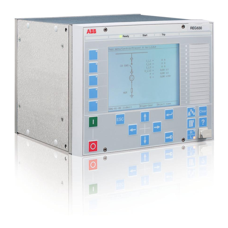
Page 20: Local Hmi
Section 2 1MRS756785 A REM630 overview Local HMI A071260 V3 EN Figure 2: 19" LHMI The LHMI of the IED contains the following elements: • Display • Buttons • LED indicators • Communication port The LHMI is used for setting, monitoring and controlling. 2.4.1 The LHMI includes a graphical monochrome LCD with a resolution of 320 x 240 pixels. - Page 21 Section 2 1MRS756785 A REM630 overview A071258 V2 EN Figure 3: Display layout 1 Path 2 Content 3 Status 4 Scroll bar (appears when needed) The function button panel shows on request what actions are possible with the function buttons. Each function button has a LED indication that can be used as a feedback signal for the function button control action.
- Page 22 Section 2 1MRS756785 A REM630 overview GUID-6828CE38-2B88-4BB5-8F29-27D2AC27CC18 V1 EN Figure 4: Function button panel The alarm LED panel shows on request the alarm text labels for the alarm LEDs. GUID-3CBCBC36-EFCE-43A0-9D62-8D88AD6B6287 V1 EN Figure 5: Alarm LED panel The function button and alarm LED panels are not visible at the same time. Each panel is shown by pressing one of the LCD function buttons or the Multipage button.
-
Page 23: Leds
Section 2 1MRS756785 A REM630 overview 2.4.2 LEDs The LHMI includes three protection indicators above the display: Ready, Start and Trip. There are also 15 matrix programmable alarm LEDs on front of the LHMI. Each LED can indicate three states with the colors: green, yellow and red. The alarm texts related to each three-color LED are divided into three pages. -
Page 24: Authorization
Section 2 1MRS756785 A REM630 overview WHMI offers several functions. • Alarm indications and event lists • System supervision • Parameter settings • Measurement display • Disturbance records The menu tree structure on the WHMI is almost identical to the one on the LHMI. A071242 V3 EN Figure 7: Example view of the WHMI... -
Page 25: Communication
Section 2 1MRS756785 A REM630 overview At delivery, the user has full access until users are created with PCM600. Logging on is not required for the LHMI. Table 3: Predefined user categories Username User rights SystemOperator Control from LHMI, no bypass ProtectionEngineer All settings DesignEngineer... - Page 26 Section 2 1MRS756785 A REM630 overview • SNTP (Simple Network Time Protocol) • DNP3 With special time synchronization wiring: • IRIG-B REM630 Application Manual...
-
Page 27: Section 3 Rem630 Variants
Section 3 1MRS756785 A REM630 variants Section 3 REM630 variants Presentation of preconfigurations The 630 series IEDs are offered with optional factory-made application preconfigurations. The preconfigurations contribute to faster commissioning and less engineering of the IED. The preconfigurations include default functionality typically needed for a specific application. -
Page 28: Preconfigurations
Section 3 1MRS756785 A REM630 variants 3.1.1 Preconfigurations Table 4: REM630 preconfigurations Description Preconfiguration Preconfiguration A for asynchronous motor Number of instances available Table 5: Supported functions Functionality Protection Three-phase non-directional overcurrent, low stage Three-phase non-directional overcurrent, instantaneous stage Non-directional earth-fault protection, low stage Non-directional earth fault, high stage Non-directional earth fault, instantaneous stage Directional earth fault, low stage... -
Page 29: Preconfiguration A For Asynchronous Motor
Section 3 1MRS756785 A REM630 variants Functionality Disconnector Local/remote switch interface Supervision and monitoring Circuit-breaker condition monitoring Fuse failure supervision Current-circuit supervision Trip-circuit supervision Generic measured values Measured value limit supervision Energy monitoring Station battery supervision Measurement Three-phase current Three-phase voltage, phase-to-earth voltages (RMS) Three-phase voltage, phase-to-phase voltages (RMS) Residual current Residual voltage... -
Page 30: Functions
Section 3 1MRS756785 A REM630 variants The apparatus controlled by the IED is the circuit breaker. The earth switch is considered to be operated manually. The open, close and undefined states of the circuit breaker and the earth switch are indicated on the LHMI. Required interlocking is configured in the IED. - Page 31 Section 3 1MRS756785 A REM630 variants Table 6: Functions included in preconfiguration A for asynchronous motor Functions IEC 61850 ANSI Three-phase non-directional PHLPTOC1 3I> 51P-1 overcurrent protection, low stage Three-phase non-directional PHIPTOC1 (1) 3I>>> 50P/51P (1) overcurrent protection, instantaneous stage Non-directional earth-fault EFLPTOC1 >...
-
Page 32: Input/Output Signal Interfaces
Section 3 1MRS756785 A REM630 variants Functions IEC 61850 ANSI Tripping logic TRPPTRC1 I→O Three phase current CMMXU1 (1) 3I (1) 3I (1) measurement, instance 1 Three phase voltage VPPMMXU1 3Upp 3Upp measurement, phase-to-phase (RMS) Sequence current measurement CSMSQI1 Sequence voltage measurement VSMSQI1 Power monitoring with P, Q, S, PWRMMXU... -
Page 33: Preprocessing Blocks And Fixed Signals
Section 3 1MRS756785 A REM630 variants Table 8: Interface of binary outputs Hardware module instance Hardware channel Description BO1_PO Master Trip 1 BO2_PO Motor start BO3_PO Master Trip 2 BO4_PO Restart enable BO5_PO Backup trip BO6_PO Not connected BO7_SO Common operate BO8_SO Common start BO9_SO... -
Page 34: Control Functions
Section 3 1MRS756785 A REM630 variants 3.2.5 Control functions 3.2.5.1 Motor bay control QCCBAY Bay control is used to handle the selection of the operator place per bay. It provides blocking functions that can be distributed to different apparatuses within the bay. Bay control sends information about the permitted source to operate (PSTO) and blocking conditions to other functions within the bay, for example switch control functions. -
Page 35: Protection Functions
Section 3 1MRS756785 A REM630 variants SCILO function checks for these conditions and provides a closing and opening enable signal. The enable signal is used by GNRLCSWI function blocks which check for the operator place selector before providing the final open or close signal to DAXSWI function. -
Page 36: Emergency Start Esmgapc
Section 3 1MRS756785 A REM630 variants reaches 100 percent, the function block generates a trip command to stop the motor. To prevent successive restarting of the motor when the motor temperature is high, restarting of the motor is inhibited if the thermal content exceeds the set restart inhibit level. -
Page 37: Loss Of Load Protection Loflptuc
Section 3 1MRS756785 A REM630 variants The set of three phase currents, I3P, is connected to the inputs. The function operates when the measured current is above the setting. The operation characteristic is definite time. The operate signal is used to trigger the disturbance recorder and to provide a LED indication on the LHMI. -
Page 38: Phase Reversal Protection Prevptoc
Section 3 1MRS756785 A REM630 variants 3.2.6.6 Phase reversal protection PREVPTOC The phase reversal protection is used for detecting the reversed connection of the phases to a three-phase motor by monitoring the negative-phase sequence current of the motor. The operation of the function is based on the detection of very high negative- sequence currents during motor start up due to incorrect phase connections to the motor. -
Page 39: Non-Directional Overcurrent Protection Phxptoc
Section 3 1MRS756785 A REM630 variants GUID-76CCD7FC-6435-476A-93EB-35411E87FC96 V1 EN Figure 11: Motor negative-sequence overcurrent protection 3.2.6.8 Non-directional overcurrent protection PHxPTOC The three-phase non-directional overcurrent functions are used for non-directional one-phase, two-phase and three-phase overcurrent and short-circuit protection with definite time or various inverse definite minimum time (IDMT) characteristic. The operation of a stage is based on three measuring principles: DFT, RMS or peak-to- peak values. -
Page 40: Non-Directional Earth-Fault Protection Efxptoc
Section 3 1MRS756785 A REM630 variants An operate and start signal from the low stage is used to provide a LED indication on the LHMI. Separate start and operate signals from both functions are connected to the disturbance recorder. 3.2.6.9 Non-directional earth-fault protection EFxPTOC The non-directional earth-fault protection functions are used for protection under earth-fault conditions with definite-time (DT) or with inverse definite minimum... -
Page 41: Circuit-Breaker Failure Protection Ccbrbrf
Section 3 1MRS756785 A REM630 variants The operate and start signals are used to provide a LED indication on the LHMI and they are also connected to the disturbance recorder. GUID-63612F53-F1C1-48E1-B940-DA878C64479A V1 EN Figure 12: Negative-sequence overvoltage protection 3.2.6.13 Circuit-breaker failure protection CCBRBRF The function is activated by the common operate command from the protection functions. -
Page 42: Tripping Logic Trpptrc
Section 3 1MRS756785 A REM630 variants 3.2.6.14 Tripping logic TRPPTRC Tripping logic has been configured to provide tripping signal of required duration to Master trip 1 and Master trip 2 circuit. The tripping circuit opens the circuit breaker on • Receipt of operate signal from the protection function or •... -
Page 43: Combined Restart Inhibit And Restart Enable Signal
Section 3 1MRS756785 A REM630 variants 3.2.6.16 Combined restart inhibit and restart enable signal The restart inhibit signals from the motor thermal protection, negative-sequence overcurrent and motor startup protection function are combined in an OR-gate to obtain a common restart inhibit signal. This signal is also connected to the disturbance recorder and it provides a LED indication on the LHMI. -
Page 44: Measurement And Analog Recording Functions
Section 3 1MRS756785 A REM630 variants inputs. Function requires also pressure lockout input and spring charged input connected via binary input COM_101.BI12 and COM_101.BI13 respectively. Various alarm outputs from the function are combined in an OR-gate to create a master circuit-breaker monitoring alarm. All of the alarms are separately connected to the binary recorder and a combined alarm is available as an indication via a LED on the LHMI. - Page 45 Section 3 1MRS756785 A REM630 variants All analog input channels are connected to the analog disturbance recorder. When any of these analog values violate the upper or lower threshold limits, the recorder unit is triggered which in turn will record all the signals connected to the recorder. Table 10: Signals connected to the analog recorder Channel ID...
-
Page 46: Binary Recording And Led Configuration
Section 3 1MRS756785 A REM630 variants 3.2.9 Binary recording and LED configuration All of the start and operate outputs from the respective protection functions, various alarms from supervision functions, and important signals from control and protective functions are connected to a binary recorder. In case of a fault, the binary recorder is triggered which in turn will record all the signals connected to the recorder. - Page 47 Section 3 1MRS756785 A REM630 variants Channel ID Description Channel 33 Backup trip from circuit-breaker failure protection Channel 34 Retrip from circuit-breaker failure protection Channel 35 Trip circuit alarm 1 (supervising motor stop circuit 1) Channel 36 Trip circuit alarm 2 (supervising motor stop circuit 2) Channel 37 Trip circuit alarm 3 (supervising motor start circuit 3) Channel 38...
- Page 48 Section 3 1MRS756785 A REM630 variants LED No LED color Description LED 10 Current circuit failure LED 11 Operate signal for thermal stress (IIT) LED 12 Motor stall at start LED 13 Yellow Motor startup in progress LED 14 Green Restart enabled LED 14 Restart inhibited...
-
Page 49: Section 4 Requirements For Measurement Transformers
Section 4 1MRS756785 A Requirements for measurement transformers Section 4 Requirements for measurement transformers Current transformers 4.1.1 Current transformer requirements for non-directional overcurrent protection For reliable and correct operation of the overcurrent protection, the CT has to be chosen carefully. The distortion of the secondary current of a saturated CT may endanger the operation, selectivity, and co-ordination of protection. -
Page 50: Non-Directional Overcurrent Protection
Section 4 1MRS756785 A Requirements for measurement transformers The CT accuracy primary limit current describes the highest fault current magnitude at which the CT fulfils the specified accuracy. Beyond this level, the secondary current of the CT is distorted and it might have severe effects on the performance of the protection IED. -
Page 51: Example For Non-Directional Overcurrent Protection
Section 4 1MRS756785 A Requirements for measurement transformers The factor 0.7 takes into account the protection IED inaccuracy, current transformer errors, and imperfections of the short circuit calculations. The adequate performance of the CT should be checked when the setting of the high set stage overcurrent protection is defined. - Page 52 Section 4 1MRS756785 A Requirements for measurement transformers A071142 V1 EN Figure 16: Example of three-stage overcurrent protection The maximum three-phase fault current is 41.7 kA and the minimum three-phase short circuit current is 22.8 kA. The actual accuracy limit factor of the CT is calculated to be 59.
-
Page 53: Section 5 Glossary
Section 5 1MRS756785 A Glossary Section 5 Glossary 100BASE-FX A physical media defined in the IEEE 802.3 Ethernet standard for local area networks (LANs) that uses fibre- optic cabling ANSI American National Standards Institute BI/O Binary input/output Binary input and output COMTRADE Common format for transient data exchange for power systems. - Page 54 Section 5 1MRS756785 A Glossary LHMI Local human-machine interface PCM600 Protection and Control IED Manager REM630 Motor protection and control IED RJ-45 Galvanic connector type Root-mean-square (value) SNTP Simple Network Time Protocol Software TCP/IP Transmission Control Protocol/Internet Protocol Trip-circuit supervision Voltage transformer Wide area network WHMI...
- Page 56 Contact us ABB Oy Distribution Automation P.O. Box 699 FI-65101 VAASA, Finland Phone +358 10 22 11 +358 10 22 41094 www.abb.com/substationautomation...