GE F650 Instruction Manual
Digital bay controller
Hide thumbs
Also See for F650:
- Instruction manual (534 pages) ,
- User manual (323 pages) ,
- User manual (298 pages)
Table of Contents
Advertisement
Quick Links
Download this manual
See also:
User Manual
GE
Digital Energy
GE Digital Energy
650 Markland Street, Markham, Ontario
Canada L6C 0M1
Tel: +1 905 927 7070 Fax: +1 905 927 5098
E gemultilin@ge.com
www.GEDigitalEnergy.com
F650
Digital Bay Controller
Instructions Manual
GEK-106310AB
Firmware version: 5.6x
EnerVista F650 Setup version: 6.2x
Copyright © 2014 GE Digital Energy
GE Digital Energy
Avda. Pinoa, 10
48170 Zamudio ESPAÑA
T +34 94 485 88 00 F +34 94 485 88 45
E gemultilin.euro@ge.com
Advertisement
Table of Contents

Related Manuals for GE F650


Summary of Contents for GE F650
- Page 1 Digital Energy F650 Digital Bay Controller Instructions Manual GEK-106310AB Firmware version: 5.6x EnerVista F650 Setup version: 6.2x Copyright © 2014 GE Digital Energy GE Digital Energy GE Digital Energy Avda. Pinoa, 10 650 Markland Street, Markham, Ontario 48170 Zamudio ESPAÑA...
-
Page 2: Table Of Contents
1.3 ENERVISTA 650 SETUP SOFTWARE 1.3.1 SYSTEM REQUIREMENTS ................1-12 1.3.2 INSTALLATION....................1-12 1.3.3 CONNECTING ENERVISTA 650 SETUP WITH F650 ........1-16 1.4 650 HARDWARE 1.4.1 MOUNTING & WIRING ................... 1-18 1.4.2 650 COMMUNICATIONS................1-18 1.4.3... - Page 3 FLEX CURVES ....................5-24 5.3.3 BREAKER......................5-26 5.3.4 SWITCHGEAR ....................5-28 5.3.5 TIME SETTINGS ....................5-28 5.4 PROTECTION ELEMENTS 5.4.1 CHANGE OF SETTING TABLES IN F650 ELEMENTS ........5-30 5.4.2 INVERSE TIME CURVES CHARACTERISTICS..........5-34 5.4.3 PHASE CURRENT ...................5-44 5.4.4 NEUTRAL CURRENT ..................5-55 5.4.5 GROUND CURRENT ..................5-61 5.4.6...
- Page 4 OPERATION BITS ..................... 6-2 6.2.2 BREAKER ......................6-2 6.2.3 PROTECTION....................6-3 6.2.4 CONTROL ELEMENTS ................... 6-10 6.2.5 PROTECTION SUMMARY ................6-17 6.2.6 SNAPSHOT EVENTS SUMMARY..............6-20 6.2.7 MODBUS USER MAP..................6-22 6.2.8 SWITCHGEAR STATUS.................. 6-22 GEK-106310AB F650 Digital Bay Controller...
- Page 5 7. IEC 61850 PROTOCOL 7.1 IEC61850 GENERIC SUBSTATION STATE EVENT (GSSE) 7.1.1 REMOTE DEVICES....................7-1 7.1.2 REMOTE INPUTS ....................7-3 7.1.3 REMOTE OUTPUTS ..................7-4 7.2 IEC 61850 PROFILE FOR F650 7.2.1 OVERVIEW ......................7-6 7.2.2 COMMUNICATION PROFILES .................7-8 7.2.3 TCP CONNECTION TIMING ................7-8 7.2.4 MMS PROTOCOL ....................7-8...
- Page 6 11.1 EXAMPLE 1: COMMUNICATION & PROTECTION SETTINGS PROCEDURE 11.1.1 DESCRIPTION OF THE EXERCISE ............... 11-1 11.1.2 PROCEDURE TO COMMUNICATE WITH THE RELAY ......... 11-1 11.1.3 PROCEDURE TO SET THE PROTECTION FUNCTION ........ 11-3 11.1.4 TEST ........................ 11-4 GEK-106310AB F650 Digital Bay Controller...
- Page 7 12.4 RELAY CONFIGURATION 13. F650TROUBLESHOOTING 13.1 SYMPTOMS AND RECOMMENDED ACTIONS GUIDE A. LOGIC OPERANDS A.1 LOGIC OPERANDS B. MODBUS PROTOCOL B.1 ACCESS TO F650 DATA B.2 MODBUS F650 B.2.1 FUNCTIONS USED ................... B-2 B.2.2 PHYSICAL LAYER .................... B-2 B.2.3 DATA LINK LAYER ................... B-3 B.2.4...
- Page 8 CONFIGURING DNP USER MAP ..............C-12 C.5.2 EXAMPLE OF CUSTOM BINARY INPUT POINTS MAP ........C-14 C.5.3 MULTIPLE DNP 3.0 MASTERS COMMUNICATION WITH F650 ....C-16 C.6 BINARY OUTPUT AND CONTROL RELAY OUTPUT C.7 BINARY COUNTERS C.8 ANALOG INPUTS D. IEC 60870-5-104 PROTOCOL D.1 INTRODUCTION...
- Page 9 TABLE OF CONTENTS F650 Digital Bay Controller GEK-106310AB...
-
Page 10: Getting Started
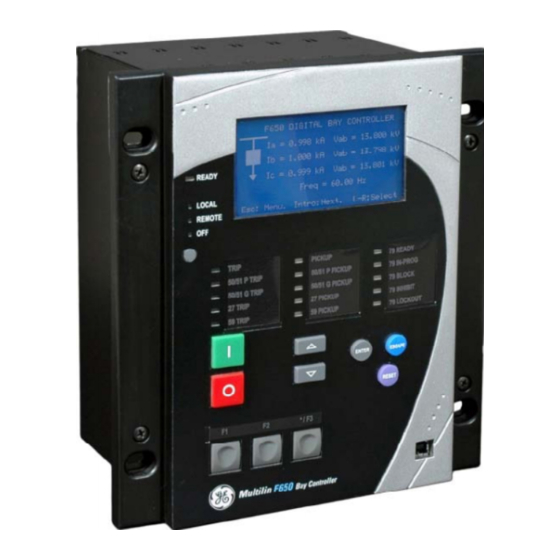
CAUTION: THE OPERATOR OF THIS INSTRUMENT IS ADVISED THAT IF THE EQUIPMENT IS USED IN A MANNER NOT SPECIFIED IN THIS MANUAL, THE PROTECTION PROVIDED BY THE EQUIPMENT MAY BE IMPAIRED. Figure 1–1: FRONT VIEW OF F650 UNITS GEK-106310AB F650 Digital Bay Controller... - Page 11 Check that the relay is fully operative. Figure 1–2: MODULE WITHDRAWAL/INSERTION GE Multilin will not be responsible for any damage of the relay, connected equipment or personnel whenever these safety rules are not followed.
- Page 12 It is very important, for safety reasons not to change or switch the terminals for CTs and VTs. AC Input Terminals Figure 1–3: REAR VIEW OF F650 UNIT will not be responsible for any damage of the relay, connected equipment or personnel GE Multilin whenever these safety rules are not followed.
-
Page 13: Inspection Checklist
1.1.2 INSPECTION CHECKLIST Unwrap the relay and inspect the relay for physical damage. Verify that the model on the label on the side of the relay matches the model ordered. Figure 1–4: IDENTIFICATION LABEL (A4455P6) F650 Digital Bay Controller GEK-106310AB... - Page 14 • Certificate of Compliance For product information, instruction manual updates, and the latest software updates, please visit the GE Multilin Home Page www.geindustrial.com/multilin. Note: If there is any physical damage detected on the relay, or any of the contents listed are missing, please...
-
Page 15: Safety Instructions
Figure 1–5: LOCATION OF GROUNDING SCREW Before communicating with a F650 unit through the front serial port, please ensure that the computer is grounded. In case of using a laptop, it is recommended not to have it connected to its power supply. In many cases it might not be correctly grounded either due to the power supply or to the connector cables used. - Page 16 AVERTISSEMENT: Laser de classe 1M (IEC60825-1) ÉVITER DE REGARDER DIRECTEMENT LE DISPOSITIF QUI ÉMET LE LASER OPTIQUE. CAUTION: Hot surface. AVERTISSEMENT: Surface chaude. Earth (Ground) Terminal. Terminal de terre (masse). Protective Earth Terminal. Terminal de terre de protection. GEK-106310AB F650 Digital Bay Controller...
-
Page 17: Overview
Input Elements accept a variety of analog or digital signals from the field. The 650 isolates and converts these signals into logic signals used by the relay. Output Elements convert and isolate the logic signals generated by the relay into digital signals that can be used to control field devices. F650 Digital Bay Controller GEK-106310AB... - Page 18 Remote inputs and outputs provide a means of sharing digital point state information between remote devices using IEC 61850 GSSE and GOOSE messages. Not available for G650 models. Analog Inputs are signals associated with transducers. GEK-106310AB F650 Digital Bay Controller...
-
Page 19: Software Architecture
Redundant 10/100BaseTX ports For options C and D it is required to select the active physical media, by means of an internal selector inside the module. The factory configuration for this selection is the 10/100BaseTX port. 1-10 F650 Digital Bay Controller GEK-106310AB... - Page 20 CAN BUS I/Os. This fact provides increased communication speed, as well as the possibility of acknowledgement of modules, abnormalities, etc. As this is a serial port supporting a communications protocol, it provides extraordinary immunity against external or internal disturbances. Figure 1–7: COMMUNICATIONS ARCHITECTURE (B6816F1) GEK-106310AB F650 Digital Bay Controller 1-11...
-
Page 21: Enervista 650 Setup Software
1.3.2 INSTALLATION After ensuring the minimum requirements for using EnerVista 650 Setup are met (see previous section), use the following procedure to install the EnerVista 650 Setup from the GE EnerVista CD. Insert the GE EnerVista CD into your CD-ROM drive. - Page 22 Install Software window as shown below. Select the “Web” option to ensure the most recent software release, or select “CD” if you do not have a web connection, then click the Add Now button to list software items for the F650.
- Page 23 11. When the Choose Destination Location window appears, and if the software is not to be located in the default directory, click Change… and type in the complete path name including the new directory name and click Next to continue with the installation procedure. Figure 1–12: ENERVISTA 650 SETUP INSTALLATION CONT. 1-14 F650 Digital Bay Controller GEK-106310AB...
- Page 24 Click Next to begin the installation process, and all the necessary program files will be copied into the chosen directory. Figure 1–13: SELECT PROGRAM FOLDER 13. To finish with the installation process, select the desired language for startup. Figure 1–14: LANGUAGE WINDOW GEK-106310AB F650 Digital Bay Controller 1-15...
-
Page 25: Connecting Enervista 650 Setup With F650
1.3 ENERVISTA 650 SETUP SOFTWARE 1 GETTING STARTED 14. Click Finish to end the installation. The F650 device will be added to the list of installed IEDs in the EnerVista Launchpad window, as shown below. Figure 1–15: ENERVISTA LAUNCHPAD 1.3.3 CONNECTING ENERVISTA 650 SETUP WITH F650 This section is intended as a quick start guide to using the EnerVista 650 Setup software. - Page 26 Before starting, verify that the RS232 serial cable, or the USB Cable, is properly connected to the RS232 port or the USB port on the front panel of the relay. Install and start the latest version of the EnerVista 650 Setup software (available from the GE EnerVista CD or online from http://www.GEindustrial.com/multilin...
-
Page 27: Hardware
USB shielded wire is needed To communicate through the F650 rear RS485 port from a PC RS232 port, the GE Multilin RS232/RS485 converter box is required. This device (catalog number F485) connects to the computer using a “straight-through” serial cable. A shielded twisted-pair (20, 22 or 24 AWG according to American standards;... -
Page 28: Faceplate Display
Figure 1–17: RS485 CONNECTION FOR 650 UNITS To communicate through the F650 rear Ethernet port from a PC a crossover cable is required. If the connection is performed through a hub or a switch, a direct Ethernet cable is required. - Page 29 View the event recorder and oscillography or fault report for correct operation of inputs,outputs and elements. If it is concluded that the relay or one of its modules is of concern, contact GE Multilin or one of its representative for prompt service.
-
Page 30: Product Description
2 PRODUCT DESCRIPTION 2.1OVERVIEW 2.1.1 F650 OVERVIEW F650 is a protection, control, monitoring, metering and registering unit, suitable for many different applications, such as main protection for distribution feeders and transmission lines, as well as backup protection for transformers, busbars, capacitor banks, etc. -
Page 31: Ansi Device Numbers And Functions
Phase Time Overcurrent with Voltage Restraint (two elements, High and Low) 51SG Ground Time Overcurrent for sensitive ground systems (measured from 5 current transformer) Phase Directional 67SG Sensitive Ground Directional Autoreclose (Four shot recloser) Frequency Rate of Change I2/I1 Broken Conductor Load Encroachment F650 Digital Bay Controller GEK-106310AB... -
Page 32: Other Device Functions
Easy menu management thanks to shuttle key Oscillography (up to 20 records) Configurable One-Line Diagram (Graphic Snapshot Events (up to 479) Operations (up to 24) model only) Phasor Diagram (available in EnerVista 650 Web Server Application Setup) GEK-106310AB F650 Digital Bay Controller... -
Page 33: Ordering Code
2.3F650 units are supplied as ½ 19” rack, 6 units high, containing the following modules: power supply, CPU, I/O modules, communication modules. The required information to completely define an F650 model is shown on Table 2–1: Table 2–1: ORDERING CODE... - Page 34 (Remote CAN Bus I/O module) for using up to 2 additional boards. F650 units allow monitoring and configuring these I/O boards as if they were internal boards, located on slots F and G. In this case, slots are labeled as H y J.
-
Page 35: Technical Specifications
Timing accuracy Operate at > 1.03 times the pickup ±3% of operate time or 50 ms. (whichever is greater) Voltage restraint Selectable by setting Saturation Level 48 times the pickup level Snapshot Events Selectable by setting F650 Digital Bay Controller GEK-106310AB... - Page 36 Instantaneous or time delayed according to IEEE Timing accuracy Operate at > 1.03 times the pickup ±3% of operate time or 50 ms. (whichever is greater) Saturation Level 48 times the pickup level Snapshot Events Selectable by setting GEK-106310AB F650 Digital Bay Controller...
- Page 37 <50 ms at 3 x Pickup at 50 Hz, typically Timing accuracy at 0 ms time delay (no intentional delay): 50ms at non-zero time delay: ±3% of operate time or 50 ms (whichever is greater) Snapshot Events Selectable by setting F650 Digital Bay Controller GEK-106310AB...
- Page 38 <50 ms at 3 x Pickup at 50 Hz, typically Timing accuracy at 0 ms time delay (no intentional delay): 50ms at non-zero time delay: ±3% of operate time or 50 ms (whichever is greater) Snapshot Events Selectable by setting GEK-106310AB F650 Digital Bay Controller...
- Page 39 Instantaneous or time delayed according to IEEE Timing accuracy Operate at > 1.03 times the pickup ±3% of operate time or 50 ms. (whichever is greater) Saturation Level 48 times the pickup level Snapshot Events Selectable by setting 2-10 F650 Digital Bay Controller GEK-106310AB...
- Page 40 Polarizing Current threshold 0.005 A Characteristic angle -90º to +90º in steps of 1º Block Logic Permission or Block selectable by setting ±3º for I>0.1 A and V>5 Vac Angle accuracy Operate time <30ms, typically GEK-106310AB F650 Digital Bay Controller 2-11...
- Page 41 Reset delay 0.00 to 900.00 s. in steps of 0.01 s. Timing accuracy ±3.5% of operate time or 50 ms. (whichever is greater) Logic Any/Two/All phases logic selectable by setting Snapshot Events Selectable by setting 2-12 F650 Digital Bay Controller GEK-106310AB...
- Page 42 0.00 to 900.00 s. in steps of 0.01 s Reset delay 0.00 to 900.00 s. in steps of 0.01 s Timing accuracy ±3.5% of operate time or 50 ms. (whichever is greater) Snapshot Events Selectable by setting GEK-106310AB F650 Digital Bay Controller 2-13...
- Page 43 0.00 to 900.00 s. in steps of 0.01 s Minimum voltage threshold 10 to 300V in steps of 1 V Time Delay Accuracy 0 to 7 cycles Operate time Typically 10 cycles at 0.1Hz/s change Snapshot Events Selectable by setting 2-14 F650 Digital Bay Controller GEK-106310AB...
- Page 44 ±3.5% of operate time or 50 ms. (whichever is greater) Block Time after close 0.00 to 900.00 s in steps of 0.01 s Snapshot Events Selectable by setting Operate time: < 45 ms at 50 Hz, typically GEK-106310AB F650 Digital Bay Controller 2-15...
-
Page 45: Control
0.00 to 900.00 s in steps of 0.01 s Reset time 0.00 to 900.00 s in steps of 0.01 s Snapshot Events Selectable by setting Possibility to modify protection settings after each shot programmable through PLC (block signals available after each shot) 2-16 F650 Digital Bay Controller GEK-106310AB... - Page 46 ±3.5% of operate time or 50 ms. (whichever is greater) Snapshot Events Selectable by setting Operation Threshold 0.000 to 1.000 A in steps of 0.001 A I2/I1 current inhibition level Selectable by setting from 0.000 to 1.000 in steps of 0.001 A GEK-106310AB F650 Digital Bay Controller 2-17...
- Page 47 -100000.000 to 100000.000 in steps of 0.001 Analog Delay 0.00 to 900.00 in steps of 0.01 Analog Hysteresis 0.0 to 50.00 in steps of 0.1 Analog Direction (for activation inside or outside the IN or OUT deadband) 2-18 F650 Digital Bay Controller GEK-106310AB...
- Page 48 0.03 to 0.25 s in steps of 0.01 s t integration Time Maximum openings 0 to 9999 in steps of 1 Maximum Openings in one hour 1 to 60 in steps of 1 Snapshot Events Selectable by setting GEK-106310AB F650 Digital Bay Controller 2-19...
-
Page 49: Monitoring
Up to 10 fault report records. Data: Fault date and time, pre-fault currents and voltages, fault currents and voltages, fault type, distance to the fault (fault location), line parameters, recloser and breaker status information. 2-20 F650 Digital Bay Controller GEK-106310AB... - Page 50 Samples: 5, 10, 15, 20, 30, 60 minutes. ±2% Accuracy: Trigger Input Selectable by setting (operation mode selection for the Block Interval calculation method) Snapshot Events: Selectable by setting GEK-106310AB F650 Digital Bay Controller 2-21...
-
Page 51: User-Programmable Elements
The following 10 ones (yellow and green) are self-reset but can be latched through PLC configuration. The LED’s can be reset by hardware, pressing the front “esc” key during more Reset Signal: than 3 seconds or using the LED reset signal through PLC configuration. 2-22 F650 Digital Bay Controller GEK-106310AB... -
Page 52: Metering
±2.0% of the reading at-0.2 ≤ PF ≤ 0.2 Accuracy: 2.4.5.5 APPARENT POWER (VA) ±2.0% of the reading Accuracy: 2.4.5.6 WATT-HOURS (POSITIVE AND NEGATIVE) ±2.0% of the reading Accuracy: Range: -2147483 to +2147483 MWh Parameters: 3-phase only Update rate: 100 ms GEK-106310AB F650 Digital Bay Controller 2-23... - Page 53 2.4.6.1 AC CURRENT INPUTS CT Ratio: 1.0 to 6000.0 in steps of 0.1 Rated currents: Appropriate for 1 or 5 A. F650 has universal range for CT (valid for 1 or 5 A to only one terminal). Relay Burden: < 0.04 Ohm...
- Page 54 0 to -1; 0 to +1; -1 to +1; 0 to 5; 0 to 10; 0 to 20; 4 to 20 (programmable) Conversion Range: -1 to +20mA ±0.2% of full scale Accuracy: Type: Passive GEK-106310AB F650 Digital Bay Controller 2-25...
-
Page 55: Real Time Clock
If the current in the tripping circuit is maintained over 500 mA, the function is sealed independently of the status of the function that caused the trip. 2.4.8.1 REMOTE OUTPUTS (IEC61850 GSSE/GOOSE) Standard output points User output points 2-26 F650 Digital Bay Controller GEK-106310AB... -
Page 56: Control Power Supply
Cable CAN port for I/O module Model M Cable CAN port for I/O module (cable) + RS485 (ModBus RTU) Optic Features for ST connectors Wave length: 1300nm devices: Fiber type: multimode 62.5/125 μm or 50/125 μm GEK-106310AB F650 Digital Bay Controller 2-27... - Page 57 Response time to ModBus commands: 10 ms Typical Isolation: 2 kV In Models C and D, the 10/100BaseTX port is selected by an internal switch (see 3.3.3) Two witness LED’s for transmission and reception are included 2-28 F650 Digital Bay Controller GEK-106310AB...
-
Page 58: Optic Features
At the Beginning of Life (BOL). Over the specified operating temperature and voltage ranges. All conditions for Note 3 apply except that the measurement is made at the center of the symbol with no window time- width. GEK-106310AB F650 Digital Bay Controller 2-29... -
Page 59: Environmental Characteristics
Seismic Type test report available upon request. F650 has been designed to comply with the highest existing requirements. More specifically, UNIPEDE recommendations for high voltage substations are followed, even if for most applications such high classes are not required. The relay complies with ANSI C37.90 standards, and has been designed to comply with international standards. -
Page 60: External Connections
2 PRODUCT DESCRIPTION 2.5 EXTERNAL CONNECTIONS 2.5EXTERNAL CONNECTIONS C O S Figure 2–2: F650 WIRING DIAGRAM (189C4216H2) GEK-106310AB F650 Digital Bay Controller 2-31... - Page 61 79 INITIATE I SENS RECLOSE F14 + CC8 F15 + COIL 2 52/a SUPERVISION TRIP F17 + COIL 2 52/b SUPERVISION F18 - 52/b Figure 2–3: INPUT/OUTPUT CONFIGURATIONS FOR BOARDS F1 AND F2 (189C4216H1) 2-32 F650 Digital Bay Controller GEK-106310AB...
-
Page 62: Hardware
Digital Supply SCREEN Figure 3–1: BLOCK DIAGRAM F650 units incorporate the following modules: • Power supply, which can be simple or redundant, depending on the selected model • Front module with alphanumerical (4 x 20) or optional graphical (16 x 40 characters) display. It includes the bus on its rear, which communicates with the rest of modules via a high speed CAN bus. -
Page 63: Power Supply
3 HARDWARE 3.2POWER SUPPLY F650 can incorporate a simple or redundant power supply. The power supply module is fixed to the base plate using 4 screws, and the main and backup modules are identical. These modules work in parallel continuously, distributing the 50% of the load for each of them, thus ensuring greater reliability, and an instantaneous load transfer from the failed power supply to the other one, without loss of time or module reset. -
Page 64: Mechanical Description
The user has access to the front keypad, display and communication port. The wiring is at the rear of the unit. The drilling dimensions are shown on Figure 3–4: Figure 3–3: PANEL MOUNTING The relay width allows the mounting of two units on a standard 19’’ panel, 8 units high. GEK-106310AB F650 Digital Bay Controller... - Page 65 3.3 MECHANICAL DESCRIPTION 3 HARDWARE Figure 3–4: DRILLING DIMENSIONS DIAGRAM F650 Digital Bay Controller GEK-106310AB...
- Page 66 3 HARDWARE 3.3 MECHANICAL DESCRIPTION Figure 3–5: DIMENSIONS OF THE 19” RACKS 8U HIGH FOR TWO RELAYS GEK-106310AB F650 Digital Bay Controller...
-
Page 67: Rear Description
15 A at 300 V. These terminal blocks admit a cable section of up to 2.54 mm (AWG 12). The communication boards have a different type of connector depending on the selected media: RS485, glass or plastic fiber optic. F650 Digital Bay Controller GEK-106310AB... - Page 68 3 HARDWARE 3.3 MECHANICAL DESCRIPTION Figure 3–6: CONNECTORS LOCATION GEK-106310AB F650 Digital Bay Controller...
- Page 69 It is very important, for safety reasons not to change or swift the terminals for CTs and VTs. F650 Digital Bay Controller GEK-106310AB...
- Page 70 3 HARDWARE 3.3 MECHANICAL DESCRIPTION A grounded antistatic wristband must be used when manipulating the module in order to avoid electrostatic discharges that may cause damage to the electronic components. Figure 3–9: REAR TERMINALS LOCATION GEK-106310AB F650 Digital Bay Controller...
-
Page 71: Wiring
3.4 WIRING 3 HARDWARE 3.4WIRING 3.4.1 EXTERNAL CONNECTIONS F650 units can hold different optionsfor F module: Option 1: Board with 16 digital inputs and 8 outputs. Option 2: Board with 8 digital inputs, 4 circuit supervision inputs, 6 conventional outputs, and two current sensing... -
Page 72: Cable/Fiber Ethernet Board
The default port selected by switch is 10/100 TX in factory configuration. The switch selects between cable (10/100 TX) and the first fiber port (100 FX). In Ethernet board type D (double fiber port) the backup channel is always fiber. Figure 3–10: FIBER/CABLE SELECTION GEK-106310AB F650 Digital Bay Controller 3-11... - Page 73 OPB (DB) FIBER OPTIC CABLE LENGTH (KM) 62.5/125 μm 50/125 μm 11.4 10.9 10.5 3-12 F650 Digital Bay Controller GEK-106310AB...
-
Page 74: Human Interfaces
4.1.2 ENERVISTA 650 SETUP SOFTWARE OVERVIEW This software package uses ModBus protocol, and it is designed to communicate with a single relay at a time. GE offers different communication software packages, such as GE-POWER, which can be used to communicate simultaneously with several relays. - Page 75 4.1.2.5 FIRMWARE UPGRADES The firmware of a F650 device can be upgraded, locally or remotely, via the EnerVista 650 Setup software. The corresponding instructions are provided by the EnerVista 650 Setup Help file under the topic ‚"Upgrading Firmware".
-
Page 76: Main Screen
The EnerVista 650 Setup software main window supports the following primary display components: • Title bar • Main menu bar • Main icon bar • Working area • Status bar Title Title Working Area Working Area Figure 4–1: ENERVISTA 650 SETUP MAIN SCREEN GEK-106310AB F650 Digital Bay Controller... -
Page 77: Communication Menu
ModBus/TCP Setup (if ModBus /TCP is selected as control type): Communication parameters for ModBus TCP communication. • Communication control: Device communication status (communicating or not communicating). • Communication optimization: allows optimizing the communication time outs and failure establishing. F650 Digital Bay Controller GEK-106310AB... - Page 78 EnerVista 650 Setup. These parameters are the maximum time to wait for a response in the relay (in ms) and the maximum attempts to perform before assuming communications failure. GEK-106310AB F650 Digital Bay Controller...
-
Page 79: File Management
*.650 for further logic changes. Figure 4–3: OFF-LINE MODE FILE MANAGEMENT 1.Note: "Relay and logic configuration" and "Protection and Control Settings" are required to be uploaded to the F650 relay in order for the device to operate properly F650 Digital Bay Controller GEK-106310AB... - Page 80 *.pep in the relay, the associated *.aut and *.lib files are also stored. File storage inside the relay "Communication > Upload info files to relay" through Ethernet (RECOMMENDED) Retrieval of files stored in the relay "Communication > Download info files from relay" through Ethernet (RECOMMENDED) GEK-106310AB F650 Digital Bay Controller...
- Page 81 Save all settings & configuration (“File>Get info from relay”) Store in the relay the Logic configuration files (*.pep, *.aut, *.lib) as well as the *.650 for further logic changes. (“Communication>Upload info files to relay”) Figure 4–4: ON LINE MODE FILE MANAGEMENT F650 Digital Bay Controller GEK-106310AB...
- Page 82 Logic programming support files (*.pep, *.aut, *.lib) CANNOT be retrieved directly from the relay. It is necessary * Either to have stored these files in the PC * Or to have uploaded previously the files into the relay ("Communication>Upload info files to relay") GEK-106310AB F650 Digital Bay Controller...
-
Page 83: Enervista 650 Setup Menu Structure
Get info Upload info files to from relay Clock (*) relay Send info Download info files to relay (*) from relay Print Setup (**) Print Preview (**) Print (**) Print to file (**) Exit 4-10 F650 Digital Bay Controller GEK-106310AB... -
Page 84: File Menu Overview
*.650 printed to file in excel format. Exit Quit the application closing all the open windows. Options enabled only in On-line mode are marked as (*). Options enabled only in Off-line mode are marked as (**) GEK-106310AB F650 Digital Bay Controller 4-11... - Page 85 "Close" option, a new *.650 can be opened without closing the previous one. The "Close" option is used to clear all data in EnerVista 650 Setup program, enabling "Language", "Upgrade firmware version" and "Upgrade Operating system" options. 4-12 F650 Digital Bay Controller GEK-106310AB...
- Page 86 When this option is selected, the program will show a screen including the relay model information, firmware version, etc. of the file being edited, as shown on Figure 4–7: Figure 4–7: FILE PROPERTIES MENU GEK-106310AB F650 Digital Bay Controller 4-13...
- Page 87 PRINT TO FILE (*XLS) Possibility to export the configuration file to an Excel file using the "Print to file (*.xls)" option. 4-14 F650 Digital Bay Controller GEK-106310AB...
- Page 88 This tool provides automatic comparison of two different configuration files, or online unit to one settings file. Open the source *.650 file and select the version and model to be compared to. Figure 4–9: COMPARE TO SETTINGS FILE It will appear the Figure 4–9: with the differences. GEK-106310AB F650 Digital Bay Controller 4-15...
-
Page 89: Setpoint Menu Overview
Options enabled only in On-line mode are marked as (*). Options enabled only in Off-line mode are marked as (**) a) COMMUNICATION SETTINGS This section details the settings related to communication parameters for the different protocols available in the F650. 4-16... - Page 90 Breaker settings, maintenance and switchgear selection of the device configured as breaker in the F650. The selected switchgear will be used in recloser, breaker failure and synchronism functions. The settings are Breaker settings...
- Page 91 Ground directional unit (67G). Voltage, current and dual polarization. SENSITIVE GROUND CURRENT Sensitive Ground TOC Sensitive ground time overcurrent (51SG). Sensitive Ground IOC Sensitive ground instantaneous overcurrent (50SG). Isolated Ground IOC Isolated ground overcurrent (50IG) 4-18 F650 Digital Bay Controller GEK-106310AB...
- Page 92 Table 4.11: GENERAL OVERVIEW OF CONTROL ELEMENTS MENU: CONTROL ELEMENTS F650 units incorporate a flexible grouping capability for protection units. This means that protection units can be used in either single setting group (default mode-all units can operate simultaneously) or three setting groups (in this mode, protection units are grouped in three independent tables, with only one of them active at a given time).
- Page 93 Options enabled only in On-line mode are marked as (*). Options enabled only in Off-line mode are marked as (**) This section shows the settings related to inputs and outputs for the different boards available in F650 (F, G, H, J).
- Page 94 Machine Interface) etc. The menu includes a library for power elements, metering elements, text and drawings. See an example on the next page. GEK-106310AB F650 Digital Bay Controller 4-21...
- Page 95 4.1 ENERVISTA 650 SETUP SOFTWARE INTERFACE 4 HUMAN INTERFACES. SETTINGS & ACTUAL VALUES The following figures show an example of the default factory configuration for F650. The F650 has no default factory configuration, but a possible example could be the following: Figure 4–10: RELAY CONFIGURATION...
- Page 96 PLC projects. 4.1.8.9 CLOCK This menu allows to update the date and time of the relay, either synchronizing them with the PC clock, or entering the information manually. GEK-106310AB F650 Digital Bay Controller 4-23...
- Page 97 4.1 ENERVISTA 650 SETUP SOFTWARE INTERFACE 4 HUMAN INTERFACES. SETTINGS & ACTUAL VALUES Figure 4–13: CLOCK 4-24 F650 Digital Bay Controller GEK-106310AB...
-
Page 98: Actual Values Menu Overview
Information related to the different records stored in the Relay, such as: Records Status Fault reports, control events, oscillography, data logger, demand, energy, and breaker maintenance. SNTP-IRIG-B Information related to synchronization via IRIG_B or SNTP GEK-106310AB F650 Digital Bay Controller 4-25... - Page 99 Status of the control events (if the signal configured to launch the control event is active or not). Oscillography Status of signals related to oscillography recording, such as status or digital channels, oscillography trigger, number of records available, etc. 4-26 F650 Digital Bay Controller GEK-106310AB...
- Page 100 Virtual Output Latched Status of Virtual Output Latched (configured in PLC Editor). Up to 16. Options enabled only in On-line mode are marked as (*). Options enabled only in Off-line mode are marked as (**) GEK-106310AB F650 Digital Bay Controller 4-27...
-
Page 101: Operations Menu Overview
Entry to first operation (with its corresponding text) Operation 24 (*) Entry to 24 operation (with its corresponding text) Options enabled only in On-line mode are marked as (*). Options enabled only in Off-line mode are marked as (**) 4-28 F650 Digital Bay Controller GEK-106310AB... -
Page 102: Communication Menu Overview
Troubleshooting (Serial or Ethernet connection): Lets the user to perform reading or writing in ModBus addresses, for verifying communications and access to different positions in the ModBus memory map. Only available if the communication has already been established. Go to "Communication>Troubleshooting". An example is provided in Figure 4–14: GEK-106310AB F650 Digital Bay Controller 4-29... - Page 103 Ethernet communication. Firmware is related to the relay internal program, designed by GE Multilin, which performs the protection and control functions, and which is run by the relay main microprocessor.
- Page 104 "Communications>Upload/Download info files to relay", stores/retrieves in the relay hard disk: settings, configuration and compiled logic equations (*.650) besides the PLC files (*.pep, *.aut, *.lib). This is only a physical storage (file backup). GEK-106310AB F650 Digital Bay Controller 4-31...
-
Page 105: Security Menu Overview
Table 4.27: GENERAL OVERVIEW OF HELP MENU: HELP Instructions Manual Instructions manual in the language selected in "View>Languages" menu. GE Mulitlin on the Web GE Multilin web page link. About EnerVista 650 Release version and date of EnerVista 650 Setup program. Setup... -
Page 106: Human Machine Interface (Hmi)
There is also a removable dust cover that fits over the display and other cover that protects the front RS232 Communications port and the commands buttons that can be sealed. The following figure shows the HMI in F650 HMI Interface DISPLAY &... -
Page 107: Display
4.2.1 DISPLAY F650 units are available with two different options for the front display. The first option is an alphanumerical display of 4 lines with 20 characters each, and the second option is a graphical display of 16 lines with 40 characters each (128x240 pixels), being B the ordering code option for the text display model (basic), and M the code for the mimic display (graphical). -
Page 108: Front Led Indicators
Rotary knob or Shuttle Key (it can be both rotated and pressed): Used for selecting menus, submenus, settings and for confirmation. Press or rotate the shuttle key to enter the text main menu from the text standby screen. Figure 4–18: KEYPAD AND SHUTTLE KEY DESCRIPTION GEK-106310AB F650 Digital Bay Controller 4-35... - Page 109 Enter Key. Press key to enter to submenus or to change values. Escape key. Press key to exit from menus Reset key. When pressed it will test all LEDs and reset the trip LEDs. Figure 4–19: ENHANCED KEYPAD DESCRIPTION 4-36 F650 Digital Bay Controller GEK-106310AB...
-
Page 110: Front Port And Cover Sealing System
Cover sealing system Screen contrast regulator Electrically isolated RS232 port Local/remote Operations access Figure 4–20: DETAIL OF FRONT PORT AND COVER SEALING SYSTEM GEK-106310AB F650 Digital Bay Controller 4-37... -
Page 111: Text Menus
When rotating the shuttle key the selected menu is marked by a single scroll bar character. The mark (>) in the right part of any menu means that contains more than one level. Figure 4–21: Shows an example of main menu navigation: Figure 4–21: NAVIGATION IN MAIN TEXT MENU 4-38 F650 Digital Bay Controller GEK-106310AB... - Page 112 English. Press shuttle key or enter key to confirm selection. Switch the relay off and on. < - return Return to previous level Press shuttle key or enter key to return to previous level. GEK-106310AB F650 Digital Bay Controller 4-39...
- Page 113 Pulse Counters Analog Comparators Load Encroachment Switchgear Status > Switchgear 1 Switchgear... Switchgear 16 Calibration Flex Curves System Info Records Status > Fault Reports Control Events Oscillography Data logger Demand Energy Breaker Maintenan. SNTP-IRIG_B 4-40 F650 Digital Bay Controller GEK-106310AB...
- Page 114 ESC key to return to previous level if desired. This navigation will be performed the same for all the menus in Actual Values. Once the last sublevel is reached, move up and down to visualize the actual values selected. GEK-106310AB F650 Digital Bay Controller 4-41...
- Page 115 Figure 4–22: ACTUAL VALUES SCREEN DATA In the Actual Values menus are different types of data, each type of data will display its particular status type (on and off, 0 or 1, ok or fail, analog values, etc.) 4-42 F650 Digital Bay Controller GEK-106310AB...
- Page 116 Pressing the enter/shuttle key the metering screen for the snapshot event will be displayed. To exit from this screen press the ESC key and return to the snapshot events menu. Figure 4–23: SNAPSHOT EVENTS NAVIGATION IN HMI GEK-106310AB F650 Digital Bay Controller 4-43...
- Page 117 Fault reset, and they can be obtained from the relay using EnerVista 650 Setup software, at the "Actual>Records>Fault report" menu. If there is no fault report available through the display, the relay will show a "Fault report not available" message. 4-44 F650 Digital Bay Controller GEK-106310AB...
- Page 118 CAG phase CAG to ground PHASE Phase to phase faults phase A to phase B phase B to phase C phase C to phase A 3PHASE Three-phase faults (shown on the display as 3PH) Fault type not calculated GEK-106310AB F650 Digital Bay Controller 4-45...
- Page 119 Phase TOC Low 3 Phase IOC High > Phase IOC High 1 Phase IOC High 2 Phase IOC High 3 Phase IOC Low > Phase IOC Low 1 Phase IOC Low 2 Phase IOC Low 3 4-46 F650 Digital Bay Controller GEK-106310AB...
- Page 120 Isolated Gnd IOC > Isolated Gnd IOC 1 Isolated Gnd IOC 2 Isolated Gnd IOC 3 Sens. Ground Dir. > Sens. Ground Dir. 1 Sens. Ground Dir. 2 Sens. Ground Dir. 3 Neg. Seq. Current > GEK-106310AB F650 Digital Bay Controller 4-47...
- Page 121 Watt Gnd Flt High 1 Watt Gnd Flt High 2 Watt Gnd Flt High 3 Watt Gnd Flt Low > Watt Gnd Flt Low 1 Watt Gnd Flt Low 2 Watt Gnd Flt Low 3 Control Elements > 4-48 F650 Digital Bay Controller GEK-106310AB...
- Page 122 Locked Rotor 2 Locked Rotor 3 Fq Rate of Change Fq Rate of Change 1 Fq Rate of Change 2 Fq Rate of Change 3 Load Encroachment Load Encroachment 1 Load Encroachment 2 Load Encroachment 3 GEK-106310AB F650 Digital Bay Controller 4-49...
- Page 123 Once all settings inside the group have been modified, go to the last screen pressing the down key or rotating the shuttle key and press Enter. At this moment of time, the new settings will be active in the relay. Figure 4–25: CHANGE SETTINGS PROCEDURE IN HMI 4-50 F650 Digital Bay Controller GEK-106310AB...
- Page 124 Once this sequence is completed, these values will remain stored in the relay, and the display will show again the date at the bottom of the text screen. Figure 4–26: CHANGE DATE AND TIME PROCEDURE IN HMI GEK-106310AB F650 Digital Bay Controller 4-51...
- Page 125 Once the commands has been performed or the time out has expired the "Command completed" message will appear in the display. Figure 4–27: COMMANDS IN HMI 4-52 F650 Digital Bay Controller GEK-106310AB...
- Page 126 4 HUMAN INTERFACES. SETTINGS & ACTUAL VALUES 4.2 HUMAN MACHINE INTERFACE (HMI) 4.2.5.10 PASSWORDS F650 units incorporate independent passwords for protection and control, in order to prevent unauthorized keypad and display access to the relay. Settings Password: This password allows restricting access to settings changes in the relay protection elements.
- Page 127 Cod Settings: [35c0] Cod Commands: [35c0] <Push Enter> In order to obtain the decoded password from the encrypted codes provided by the relay, it is necessary to contact GE Multilin and provide these encrypted codes. 4-54 F650 Digital Bay Controller...
- Page 128 Ia 0.000 Vab 0.000 Ib 0.000 Vbc 0.000 Ic 0.000 Vca 0.000 Ig 0.000 0.000 Figure 4–29: DEFAULT METERING SCREEN This option alternates in time the two previous options. GEK-106310AB F650 Digital Bay Controller 4-55...
- Page 129 Once the new language has been selected it is necessary to reboot the relay in order to start working with the new language in the device. Figure 4–30: LANGUAGE SELECTION IN HMI 4-56 F650 Digital Bay Controller GEK-106310AB...
-
Page 130: Graphic Display
In models with graphic display (F650M) default main screen is the single-line diagram. This single-line diagram can be configured using EnerVista 650 Setup software by choosing the HMI menu inside Relay Configuration (Setpoint>Relay Configuration>HMI). F650 DIGITAL BAY CONTROLLER Ia = 0.000 kA Vab =0.000 kV Ib = 0.000 kA... - Page 131 Phase A Power Factor Negative MWatthour I0 Primary VBB Primary Phase B Power Factor I1 Primary Phase A Reactive Pwr Phase C Power Factor I2 Primary Phase A Apparent Pwr 3 Phase Power Factor 4-58 F650 Digital Bay Controller GEK-106310AB...
- Page 132 The user accesses the next available graphic screen (Events – New) <PREV> This option returns to the general events graphic menu (All Events) <RELOAD> This option updates all events stored in the relay and returns to the general events screen. GEK-106310AB F650 Digital Bay Controller 4-59...
- Page 133 ESC: Prev. If the user presses the ESC key from the event detail screen, the system will return to the all events screen. 4-60 F650 Digital Bay Controller GEK-106310AB...
- Page 134 After the new events have been read, if the user selects again the Reload menu, the system will show a <No new events available.> message, indicating that there are no more new events available since the last reading. GEK-106310AB F650 Digital Bay Controller 4-61...
- Page 135 4 HUMAN INTERFACES. SETTINGS & ACTUAL VALUES 4.2.6.5 ALARMS PANEL Alarms panel can be viewed in all F650 models using communication software EnerVista 650 Setup, however, only models with graphic display allow access to the alarms panel from the HMI.
- Page 136 The selected option will be displayed in upper case and between brackets. To access the selected option, the enter/shuttle key must be pressed. GEK-106310AB F650 Digital Bay Controller 4-63...
- Page 137 When the shuttle key is pressed, the selected input will be activated. Navigation through this screen is indicated by the following legend: Esc: Exit Text. Enter: Chg Input. 4-64 F650 Digital Bay Controller GEK-106310AB...
- Page 138 Pressing the enter/shuttle key on the blinking output, this output will be activated in emulation mode. Note: Output emulation can be executed through the TEST OUTPUT tool on the graphic display, and also through communications using EnerVista 650 Setup software for all F650 models. : Chg Card Pressing the up-down key or rotating the shuttle key allows to change the selected I/O board in the main I/O screen.
-
Page 139: Web Server 4.3.1 Home
IP address, which must be configured in Setpoint > Product Setup > Communication Settings > Ethernet. The main screen of the F650 web server shows the different monitoring possibilities for snapshot events, events, alarms, oscillography, fault reports, data logger and metering values provided by the relay through the web. -
Page 140: Snapshot Events
The bottom of the screen shows a Metering screen; clicking on one of the events, the associated metering values will be shown on that screen. Figure 4–39: SNAPSHOT EVENTS SCREEN GEK-106310AB F650 Digital Bay Controller 4-67... -
Page 141: Control Events
Unlike the case of Snapshot events, in this screen the highest index corresponds to the most recent event. The information provided is the control event index, the text that has been associated to such event when configured, its status, active (ON) or inactive (OFF), and its date and time. 4-68 F650 Digital Bay Controller GEK-106310AB... -
Page 142: Alarms
The alarms screen provides access to alarms configured in the relay. As in the case of snapshot events and control events, this screen allows only to view the alarms, but not to acknowledge them. Figure 4–41: ALARMS SCREEN GEK-106310AB F650 Digital Bay Controller 4-69... -
Page 143: Oscillography
Download button. The system will then open a window to allow saving the files in Comtrade format in the PC hard drive. Once the records have been saved, the system will ask if the user wants to open GE-OSC tool (Comtrade record viewer) to view the downloaded files. -
Page 144: Fault Report
To obtain a text file with all the fault report information, press the Download option and save the file in the computer. GEK-106310AB F650 Digital Bay Controller 4-71... -
Page 145: Data Logger
The data logger screen allows viewing the data logger first and last value retrieval date and allows downloading the data record files in Comtrade format, by pressing the Download option. Stored files can be viewed later using any Comtrade format viewer Figure 4–45: DATA LOGGER SCREEN 4-72 F650 Digital Bay Controller GEK-106310AB... -
Page 146: Metering
4 HUMAN INTERFACES. SETTINGS & ACTUAL VALUES 4.3 WEB SERVER 4.3.8 METERING This screen includes the 53 primary metering values provided by the relay display. Figure 4–46: METERING SCREEN GEK-106310AB F650 Digital Bay Controller 4-73... - Page 147 4.3 WEB SERVER 4 HUMAN INTERFACES. SETTINGS & ACTUAL VALUES 4-74 F650 Digital Bay Controller GEK-106310AB...
-
Page 148: Settings
Neutral TOC Neutral IOC Neutral Directional Ground Current Ground TOC Ground IOC Ground Directional Sensitive Ground Current. Sensitive Ground TOC Sensitive Ground IOC Isolated Ground IOC Sensitive Ground Directional Negative Sequence Current Negative Sequence TOC GEK-106310AB F650 Digital Bay Controller... - Page 149 Broken Conductor Locked Rotor Pulse Counters Analog Comparator Frequency rate of change Load Encroachment Input/Outputs Contact I/O Board F Board G Board H Board J Force Outputs. Remote Comms (Available for IEC61850 models only). Virtual Inputs F650 Digital Bay Controller GEK-106310AB...
-
Page 150: Product Setup
Table 5–4: MODBUS PROTOCOL SETTINGS PRODUCT SETUP > COMMUNICATION SETTINGS >MODBUS PROTOCOL Name Default Value Step Range ModBus Address COM1 254 [1 : 255] ModBus Address COM2 254 [1 : 255] ModBus Port Number [0 : 65535] GEK-106310AB F650 Digital Bay Controller... - Page 151 Binary Input Block 1 CTL EVENTS 1-16 Binary Input Block 2 CTL EVENTS 17-32 Binary Input Block 3 CTL EVENTS 33-48 Binary Input Block 4 CTL EVENTS 49-64 Binary Input Block 5 CTL EVENTS 65-80 F650 Digital Bay Controller GEK-106310AB...
- Page 152 If SNTP functionality is enabled at the same time as an IRIG-B source is connected to the F650, the IRIG-B signal provides the time value to the F650 clock for as long as a valid signal is present. If the IRIG-B signal is removed, the time obtained from the SNTP server is used.
- Page 153 SNTP/NTP servers are ignored. In unicast mode of operation the chosen time server can go offline, in that case it takes about one minute for the F650 to signal an SNTP FAIL state and to switch again to anycast mode to try to find another time server.
-
Page 154: Modbus User Map
PRODUCT SETUP > MODBUS USER MAP Name Default Value Step Range Address 00 0000 [0000 : FFFF] Address 01 0000 [0000 : FFFF] Address 254 0000 [0000 : FFFF] Address 255 0000 [0000 : FFFF] GEK-106310AB F650 Digital Bay Controller... -
Page 155: Fault Report
The metering element can be kilometers or miles. Show Fault On HMI: This setting enables or disables the option to display faults on the Relay HMI. Snapshot Events: This setting enables or disables the snapshot event generation for the fault report element. F650 Digital Bay Controller GEK-106310AB... - Page 156 HMI will always display the most recent one. Each stored fault will need to be acknowledged up to a maximum of 10 faults. The HMI menu offers an option to view the last 10 faults produced, that menu displays both the general information screen and the metering screen for each fault. GEK-106310AB F650 Digital Bay Controller...
-
Page 157: Oscillography
5 SETTINGS 5.2.4 OSCILLOGRAPHY 5.2.4.1 OVERVIEW F650 elements allocate 1-Mbyte of memory for storing oscillography records. These oscillography records are stored in non-volatile memory. Oscillography records are stored in COMTRADE ASCII - IEEE C37.111-1999 standard format. The oscillography module is in charge of storing the instantaneous values of the 9 analog signals and the 16 programmable digital signals at Setpoint >... -
Page 158: Oscillography
If we set the relay to 64 samples per cycle, each record will store up to 13107 / 64 = 204.79 signal cycles. This value expressed in terms of time would be: For 50 Hz: 204.79 cycles x 20 ms/cycle = 4095.8 ms. For 60 Hz: 204.79 cycles x 16.67 ms/cycle = 3413 ms. GEK-106310AB F650 Digital Bay Controller 5-11... - Page 159 AVAILABLE RECORDS: This shows the number of records stored in the relay, which can be retrieved by serial communication (ModBus RTU) or Ethernet (ftp, tftp). The range is 0 to 20. 5-12 F650 Digital Bay Controller GEK-106310AB...
-
Page 160: Data Logger
5.2.5 DATA LOGGER The F650 data logger can store information of up to 16 analog channels, among all channels available in the relay, with a sampling rate selectable by setting. The memory of the data logger is fixed, 64 Kilobytes. Two bytes are needed per channel. - Page 161 Data logger files can be retrieved only by Ethernet via 650PC software or by webserver via tftp. File Format Data logger information is made of two text files: configuration file (datalogger.cfg), and data file (datalogger.dat). 5-14 F650 Digital Bay Controller GEK-106310AB...
- Page 162 Current and Power methods can be chosen separately. Settings are provided to disable certain measuring techniques. These techniques are used by many utilities for statistical or control purposes. GEK-106310AB F650 Digital Bay Controller 5-15...
- Page 163 It calculates the equivalent thermal demand using the following equation: − − Where: Input signal (constant). d(t) Demand value after applying the input value during time t (in minutes) 2.3 / thermal 90% response time 5-16 F650 Digital Bay Controller GEK-106310AB...
- Page 164 In case the interval between two consecutive pulses exceeds 60 minutes, the relay will calculate the demand after 60 minutes from the last pulse, this measure will be updated in the status and a new demand count will start. This method calculates a linear average of the magnitude. GEK-106310AB F650 Digital Bay Controller 5-17...
- Page 165 Figure 5–1: shows the behavior of the demand, depending on the Selected setting for demand calculation. -0,2 Time (minutes) -0,2 Time (minutes) -0,2 Time (minutes) Block interval -0,2 Time (minutes) Rolling demand Figure 5–1: RESPONSE TO THE DIFFERENT DEMAND METHODS 5-18 F650 Digital Bay Controller GEK-106310AB...
-
Page 166: Demand Ix
DEMAND Y MAX Demanded maximeter; it stores the Maximum demand value until a demand reset is issued. DEMAND Y DATE Date of the Maximum demand value. Being Y the power considered in each case. GEK-106310AB F650 Digital Bay Controller 5-19... - Page 167 Bit type state, programmable at “Setpoint>Relay Configuration>Protection Elements” in the EnerVista 650 Setup software. When this bit is activated, the demand measures are reset. All stored values are reset to zero (for demand dates, this value represents January 1 , 2000). 5-20 F650 Digital Bay Controller GEK-106310AB...
-
Page 168: System Setup
When the unit goes out of the out of service state the output will be opened if it was a change. Functions affected by Out of service State - IO Boards. - PROTECTIÓN: o Generator: • § Generator Unbalance (46 gen) GEK-106310AB F650 Digital Bay Controller 5-21... - Page 169 §Breaker Failure (50BF) • §Neutral Dir (67n) • §Neutral TOC (51N) • §Phase IOC High (50PH) • §Ground IOC (50G) • §Stv Gnd Dir (67sg) • §Ground TOC (51g) o Misc: • §Forward Power (32FP) 5-22 F650 Digital Bay Controller GEK-106310AB...
- Page 170 Be careful if ready led is linked to an output, because the output will not change its state. To set an output to ready state see factory default Logic & Configuration. Take notice that VO_000 is set to the output instead of VO_099 The following figure shows the flow chart of these states GEK-106310AB F650 Digital Bay Controller 5-23...
- Page 171 ON: The operator is not able to change the operations from local to remote or OFF. 5.3.1.2.2 SETTINGS The unit will be set by the HMI and by 650Pc software as it is shown in the following figure. 5-24 F650 Digital Bay Controller GEK-106310AB...
-
Page 172: Flex Curves
In the flex curves menu there are 120 points to define a user curve. 40 points for reset (from 0 to 0.98 times the pickup value) and 80 for operate (from 1.03 to 20 times the pickup). GEK-106310AB F650 Digital Bay Controller 5-25... - Page 173 “Flex Curve > Exit with Data” menu must be selected. If the results are not to be saved, the Exit without Data option must be selected. Now, calculated points must be saved in the Flex Curve using the “Store” option. Figure 5–3: FLEXCURVES EDITION 5-26 F650 Digital Bay Controller GEK-106310AB...
-
Page 174: Breaker
5.3.3 BREAKER There are two types of breaker settings: Breaker settings: These settings correspond to the switchgear configured as a breaker in the F650; this switchgear is used in the recloser functions, breaker failure and synchronism. Breaker Maintenance: These settings correspond to the initialization of the (KI) t counters, and the counting of the number of openings and closings of the switchgear configured as a breaker. - Page 175 Reset signal for the Opening and Closing Counters. This signal is configured at Setpoint > Relay Configuration > Protection Elements, and it is used for resetting the breaker Opening and closing counters. BREAKER OPENINGS Number of Breaker openings BREAKER CLOSINGS Number of Breaker closings 5-28 F650 Digital Bay Controller GEK-106310AB...
-
Page 176: Switchgear
Real Time Clock but are still used to calculate the UTC Time (i.e., for the IEC61850 protocol), but its behavior is not assumed correct in several critical hour changes because of Daylight Savings Time getting effective. In these configuration cases, it is recommended to disable Daylight Savings Time. Table 5–27: TIME SETTINGS GEK-106310AB F650 Digital Bay Controller 5-29... - Page 177 DST STOP HOURAllow to set the stop hour of the DST (in local time) IRIG-B LOCAL TIME: Determines, in case of being enabled, if the IRIG-B protocol would carry the date in local time or else in UTC Time. 5-30 F650 Digital Bay Controller GEK-106310AB...
-
Page 178: Protection Elements
5 SETTINGS 5.4 PROTECTION ELEMENTS 5.4PROTECTION ELEMENTS 5.4.1 CHANGE OF SETTING TABLES IN F650 ELEMENTS F650 relays incorporate the following protection elements: CURRENT ELEMENTS Instantaneous overcurrent: 3 x PHASE IOC HIGH (50PH) 3 x PHASE IOC LOW (50PL) 3 x NEUTRAL IOC (50N) - Page 179 3 x FREQUENCY RATE OF CHANGE (81 df/dt) 3 x LOAD ENCROACHMENT F650 elements incorporate a flexible grouping capability for protection ELEMENTS. This means that protection elements can be used in either one of the following modes: a) SINGLE SETTING GROUPS In this operation mode, all protection elements can be activated and operated simultaneously.
- Page 180 Active Group GROUP 1 [GROUP 1 – GROUP 2 – GROUP 3] Snapshot Event generation Snapshot Events ENABLED [DISABLED – ENABLED] Setting Group settings are as follows: Function: Possible values are: [DISABLED – ENABLED] GEK-106310AB F650 Digital Bay Controller 5-33...
- Page 181 GROUP 1 BLOCKED GROUP 2 BLOCKED GROUP 3 BLOCKED All signals corresponding to setting Groups, both the activation and the block signals, are located in the Actual > Status > Control Elements > setting Groups menu. 5-34 F650 Digital Bay Controller GEK-106310AB...
-
Page 182: Inverse Time Curves Characteristics
= Operation time in seconds Dial = multiplier setting I = Input current Itap = Current pickup value A, B, p = constants defined by the standard = reset time in seconds RESET = characteristic constant. GEK-106310AB F650 Digital Bay Controller 5-35... - Page 183 5.307 5.041 4.827 38.634 22.819 14.593 11.675 10.130 9.153 8.470 7.960 7.562 7.241 51.512 30.426 19.458 15.567 13.507 12.204 11.294 10.614 10.083 9.654 10.0 64.390 38.032 24.322 19.458 16.883 15.255 14.117 13.267 12.604 12.068 5-36 F650 Digital Bay Controller GEK-106310AB...
- Page 184 43.2 IEC Curve B IEC Curve B 13.500 IEC Curve C IEC Curve C 80.000 2.000 58.2 IEC Long-Time Inverse IEC Long-Time Inv 120.000 1.000 120.0 IEC Short-Time Inverse IEC Short-Time Inv 0.050 0.040 GEK-106310AB F650 Digital Bay Controller 5-37...
- Page 185 0.207 0.60 1.835 1.067 0.668 0.526 0.451 0.404 0.371 0.346 0.327 0.311 0.80 2.446 1.423 0.890 0.702 0.602 0.538 0.494 0.461 0.435 0.415 1.00 3.058 1.778 1.113 0.877 0.752 0.673 0.618 0.576 0.544 0.518 5-38 F650 Digital Bay Controller GEK-106310AB...
- Page 186 IAC Extremely Inverse IAC Ext Inv 0.0040 0.6379 0.6200 1.7872 0.2461 6.008 IAC Very Inverse IAC Very Inv 0.0900 0.7955 0.1000 -1.2885 7.9586 4.678 IAC Inverse IAC Mod Inv 0.2078 0.8630 0.8000 -0.4180 0.1947 0.990 GEK-106310AB F650 Digital Bay Controller 5-39...
- Page 187 1.280 1.229 1.188 6.931 4.496 3.192 2.656 2.353 2.158 2.022 1.921 1.843 1.781 9.242 5.995 4.256 3.541 3.138 2.878 2.695 2.561 2.457 2.375 10.0 11.552 7.494 5.320 4.426 3.922 3.597 3.369 3.201 3.072 2.969 5-40 F650 Digital Bay Controller GEK-106310AB...
- Page 188 ANSI CURVE SHAPE ANSI Extremely Inverse 0.0399 0.2294 3.0094 0.7222 5.67 ANSI Very Inverse 0.0615 0.7989 0.34 -0.284 4.0505 3.88 ANSI Normally Inverse 0.0274 2.2614 -4.1899 9.1272 5.95 ANSI Moderately Inverse 0.1735 0.6791 -0.08 0.1271 1.08 GEK-106310AB F650 Digital Bay Controller 5-41...
- Page 189 0.986 6.00 8.106 4.544 2.866 2.291 1.994 1.812 1.689 1.600 1.532 1.479 8.00 10.807 6.059 3.821 3.054 2.659 2.416 2.252 2.133 2.043 1.972 10.00 13.509 7.574 4.776 3.818 3.324 3.020 2.815 2.666 2.554 2.465 5-42 F650 Digital Bay Controller GEK-106310AB...
- Page 190 T = Operation time (in seconds). TDM = Multiplying factor I = Input current = Pickup current pickup = Reset time (in seconds) assuming a 100% of power capacity and that the reset is activated reset GEK-106310AB F650 Digital Bay Controller 5-43...
- Page 191 EnerVista 650 Setup, which incorporates a graphical environment for viewing the curve, thus making it easy for the user to create it. This module can be accessed from the “Edit Curve” option in the FlexCurve menu, at Setpoint > System Setup > Flex Curves. 5-44 F650 Digital Bay Controller GEK-106310AB...
-
Page 192: Phase Current
5 SETTINGS 5.4 PROTECTION ELEMENTS 5.4.3 PHASE CURRENT The F650 Phase current menu incorporates the following overcurrent elements: Phase time overcurrent (51PH/51PL) Phase instantaneous overcurrent (50PH/50PL) Phase directional overcurrent (67P) Thermal Model (49) 5.4.3.1 PHASE TIME DELAYED OVERCURRENT ELEMENTS – PHASE HIGH/LOW (51PH/51PL) The phase overcurrent element (51P) operates in a time period that depends on the applied current and on the set curve. - Page 193 If the voltage restraint feature is disabled, the pickup level always remains at the value set in the Pickup Level setting. The snapshot event setting enables or disables the snapshot event generation for the phase time overcurrent elements. 5-46 F650 Digital Bay Controller GEK-106310AB...
- Page 194 5.4 PROTECTION ELEMENTS The following diagram shows the logic scheme followed by high range and low range time overcurrent elements (51PH and 51PL) in the following figure Figure 5–6: TOC ELEMENT LOGIC SCHEME (A6632F2) GEK-106310AB F650 Digital Bay Controller 5-47...
- Page 195 [0.00 : 900.00] Reset time Reset Delay 0.00 0.01 s [0.00 : 900.00] Snapshot event generation Snapshot Events ENABLED [DISABLED – ENABLED] The snapshot event setting enables or disables the snapshot event generation for these elements. 5-48 F650 Digital Bay Controller GEK-106310AB...
- Page 196 5 SETTINGS 5.4 PROTECTION ELEMENTS The following figure shows the logic scheme diagram for high range and low range Instantaneous overcurrent elements (50PH, 50PL). Figure 5–7: PHASE IOC ELEMENTS LOGIC SCHEME (A6632F1) GEK-106310AB F650 Digital Bay Controller 5-49...
- Page 197 Phase directional element is an independent Protection element that provides block and Operation signals for each phase. These signals can be monitored both through the relay HMI or using EnerVista 650 Setup at “Actual > Status > Protection > Phase Current” 5-50 F650 Digital Bay Controller GEK-106310AB...
- Page 198 “Block”, this input will be active in case of a block in the directional element, avoiding any phase overcurrent trip. When the “Block logic” setting is set as “Permission”, the phase overcurrent element is enabled to trip as the block input is not active in case of polarization voltage loss. GEK-106310AB F650 Digital Bay Controller 5-51...
- Page 199 VBC angle x 1 MTA VCB angle x 1 MTA IB angle VCA angle x 1 MTA VAC angle x 1 MTA IC angle VAB angle x 1 MTA VBA angle x 1 MTA 5-52 F650 Digital Bay Controller GEK-106310AB...
- Page 200 This time is approximately 20 ms. Certain instantaneous overcurrent elements can be activated before receiving the blocking signal from the directional element. In cases where these situations can be expected, we recommend to add a 50ms delay to IOC elements. GEK-106310AB F650 Digital Bay Controller 5-53...
- Page 201 5.4 PROTECTION ELEMENTS 5 SETTINGS The following figure shows the logic scheme for the phase directional element. Figure 5–11: DIRECTIONAL ELEMENT LOGIC SCHEME (A6632F3) 5-54 F650 Digital Bay Controller GEK-106310AB...
- Page 202 Snapshot event generation Snapshot Events ENABLED [DISABLED – ENABLED] The cooling constant is given in times the heating constant. The snapshot event setting enables or disables the snapshot event generation for the thermal model elements. GEK-106310AB F650 Digital Bay Controller 5-55...
- Page 203 [0.00 : 900.00] Reset time Reset Delay 0.00 0.01 s [0.00 : 900.00] Snapshot event generation Snapshot Events ENABLED [DISABLED – ENABLED] The snapshot event setting enables or disables the snapshot event generation for this element. 5-56 F650 Digital Bay Controller GEK-106310AB...
- Page 204 5 SETTINGS 5.4 PROTECTION ELEMENTS The following figure shows the logic scheme for the neutral Instantaneous overcurrent element. Figure 5–12: LOGIC SCHEME FOR NEUTRAL IOC ELEMENT GEK-106310AB F650 Digital Bay Controller 5-57...
- Page 205 This is the minimum voltage considered for the direction calculation. Under this setting, the element will be blocked. Snapshot Events: The snapshot event setting enables or disables the snapshot event generation for this elements. 5-58 F650 Digital Bay Controller GEK-106310AB...
-
Page 206: Neutral Current
±90º arc at both sides of the polarization current. In any other case, the direction will be Reverse. If the polarization current is lower than 5 mA, the element output takes the value of the Block Logic setting.VOLTAGE POLARIZATION GEK-106310AB F650 Digital Bay Controller 5-59... - Page 207 In cases where this situation is foreseen, it is recommended to program the Block Logic setting as Block, or else to add a small time delay to the overcurrent element to allow the directional element to polarize and block the trip. 5-60 F650 Digital Bay Controller GEK-106310AB...
- Page 208 NEUTRAL TOC3 BLOCK = NOT (NEUTRAL DIR3 OP) To block neutral instantaneous elements: NEUTRAL IOC1 BLOCK = NOT (NEUTRAL DIR1 OP) NEUTRAL IOC2 BLOCK = NOT (NEUTRAL DIR2 OP) NEUTRAL IOC3 BLOCK = NOT (NEUTRAL DIR3 OP) GEK-106310AB F650 Digital Bay Controller 5-61...
-
Page 209: Ground Current
[0.00 : 900.00] Reset type Reset INSTANTANEOUS N/A [INSTANTANEOUS – LINEAR] Snapshot Event generation Snapshot Events ENABLED [DISABLED – ENABLED] The snapshot event setting enables or disables the snapshot event generation for this element. 5-62 F650 Digital Bay Controller GEK-106310AB... - Page 210 In case of using the voltage measured from the dedicated voltage input terminals, the Auxiliary Voltage setting in General settings must be V If the F650 is set to have synchronism check protection, then this input will be adjusted as busbar voltage and it will not be the 3V0 voltage (AUXILIARY VOLTAGE setting as VX)
- Page 211 GROUND TOC3 BLOCK = NOT (GROUND DIR3 OP) To block the Ground Instantaneous elements: GROUND IOC1 BLOCK = NOT (GROUND DIR1 OP) GROUND IOC2 BLOCK = NOT (GROUND DIR2 OP) GROUND IOC3 BLOCK = NOT (GROUND DIR3 OP) 5-64 F650 Digital Bay Controller GEK-106310AB...
-
Page 212: Sensitive Ground Current
- Vo FORWARD Vo * Ip - Vo REVERSE 5.4.6 SENSITIVE GROUND CURRENT The F650 Sensitive ground Current menu incorporates the following overcurrent elements: • Sensitive ground time overcurrent (51SG) • Sensitive ground instantaneous overcurrent (50SG) • Isolated ground overcurrent (50IG) •... - Page 213 (0.5-10 A primary values). The operation characteristic is shown on figure Figure 5–14:, where Vh, Vl, Ih and Il are element settings. Operation Area Figure 5–14: OPERATION CHARACTERISTIC FOR ELEMENT 50IG 5-66 F650 Digital Bay Controller GEK-106310AB...
- Page 214 If the user doesn’t want to use this function, then the Deviation Time to Instantaneous (Time to inst) setting must be set to zero seconds. Once the time has expired, the element returns to its normal operation. GEK-106310AB F650 Digital Bay Controller 5-67...
- Page 215 System Setup > General settings must be VN. If the F650 is set to have synchronism check protection, then this input will be adjusted as busbar voltage and it will not be the 3V0 voltage (AUXILIARY VOLTAGE setting as VX) If the F650 does not have a synchronism check element, then this input can be set as 3V0 neutral voltage, and it can be used as polarization magnitude for the 67SG element (AUXILIARY VOLTAGE setting as VN).
- Page 216 SENS GND IOC3 BLOCK = NOT (SENS GND DIR3 OP) To block isolated Ground elements: ISOLATED GND1 BLK = NOT (SENS GND DIR1 OP) ISOLATED GND2 BLK = NOT (SENS GND DIR2 OP) ISOLATED GND3 BLK = NOT (SENS GND DIR3 OP) GEK-106310AB F650 Digital Bay Controller 5-69...
-
Page 217: Negative Sequence Current
Snapshot Event generation Snapshot Events ENABLED [DISABLED – ENABLED] The snapshot event setting enables or disables the snapshot event generation for this element. 5.4.8 VOLTAGE ELEMENTS The F650 incorporates the following voltage elements: • Phase undervoltage (27P) • Phase overvoltage (59P) •... - Page 218 This element generates independent pickup and trip signals per phase, and general pickup and trip signals for the element. These last signals can be selected, by means of the operation logic setting, to be an OR (any phase signal) or an AND (all phase signals). GEK-106310AB F650 Digital Bay Controller 5-71...
- Page 219 As in the case of the undervoltage element, this element generates independent pickup and trip signals for each phase. The general signal is selectable by setting to be an OR or an AND of the phase signals. 5-72 F650 Digital Bay Controller GEK-106310AB...
- Page 220 General settings, and the fourth voltage transformer input is set to the busbar voltage for the synchronism element (Vx in Auxiliary Voltage setting). This is because with this combination of settings it is not possible to calculate the zero sequence component from the phase-to-phase voltage magnitudes. GEK-106310AB F650 Digital Bay Controller 5-73...
- Page 221 [0.00 : 900.00] Reset time Reset Delay 0.00 0.01 s [0.00 : 900.00] Snapshot Event generation Snapshot Events ENABLED [DISABLED – ENABLED] The snapshot event setting enables or disables the snapshot event generation for this element. 5-74 F650 Digital Bay Controller GEK-106310AB...
- Page 222 The snapshot event setting enables or disables the snapshot event generation for this element. The F650 includes three 32FP elements. Each elements incorporates two stages, the first stage, less critical, is intended to produce an alarm, the second stage is used for trip. Both levels are set in primary values, for instance: if in general...
- Page 223 P cos(ϕ) + Q sin (ϕ) > SMIN where: P and Q are active and reactive powers as measured per the F650 convention, ϕ is the angle set at the 32 setting (DIR POWER ANGLE) in degrees in steps of 0.01º, and SMIN is the minimum operating power.
- Page 224 90º and 270º, the case would be similar but with reactive power. Figures (a, b, c, d, e, f) below shows settings for different power applications. Figure 5–18: DIRECTIONAL POWER ELEMENT SAMPLE APPLICATIONS GEK-106310AB F650 Digital Bay Controller 5-77...
- Page 225 This setting specifies the relay characteristic angle (RCA) for the directional power element. This setting provides ability to respond to the function in any direction defined (active forward power, active low forward power, etc.) 5-78 F650 Digital Bay Controller GEK-106310AB...
- Page 226 5 SETTINGS 5.4 PROTECTION ELEMENTS The following figure illustrates the conventions established: Figure 5–19: ANGLES GEK-106310AB F650 Digital Bay Controller 5-79...
- Page 227 This is activated when the element that corresponds to stage 1/2 is activated. Events generated by this element are: DIR PWR1 (2, 3) STG OP ON DIR PWR1 (2, 3) STG OP OFF 5-80 F650 Digital Bay Controller GEK-106310AB...
- Page 228 This setting specifies delay for the overcurrent portion of this element. The delay applies to the 32N1(2 3) HIGH(LOW) OC PKP operand driven from the overcurrent condition. Power Pickup: This setting specifies the operating point of the element. GEK-106310AB F650 Digital Bay Controller 5-81...
- Page 229 * stands for complex conjugate. By varying the MTA angle one could make the element to respond to forward or reverse direction in inductive, resistive, or capacitive networks as shown in the figure below. 5-82 F650 Digital Bay Controller GEK-106310AB...
- Page 230 – neutral current (3 times I_0): either calculated (IN as current selection setting) or supplied from the ground current channel (IG as current selection setting) The following figure shows the logic scheme diagram for high range and low range wattmetric ground fault elements (32NH, 32NL). GEK-106310AB F650 Digital Bay Controller 5-83...
- Page 231 5.4 PROTECTION ELEMENTS 5 SETTINGS Figure 5–21: WATTMETRIC GROUND FAULT ELEMENTS LOGIC SCHEME 5-84 F650 Digital Bay Controller GEK-106310AB...
- Page 232 32N1 (2, 3) HIGH (LOW) OP: This is activated when the element is activated. Events generated by this element are: 32N1 (2, 3) HIGH (LOW) OP ON 32N1 (2, 3) HIGH (LOW) OP OFF GEK-106310AB F650 Digital Bay Controller 5-85...
-
Page 233: Setting Group
5.5 CONTROL ELEMENTS 5 SETTINGS 5.5CONTROL ELEMENTS The F650 incorporates the following control elements: Setting Group Underfrequency Overfrequency Synchrocheck (25) Autoreclose (79) Breaker Failure (50BF) VT Fuse Failure Broken Conductor (I2/I1) Locked Rotor Pulse Counters Analog Comparators Frequency Rate of Change (81 df/dt) -
Page 234: Underfrequency Element (81U)
The snapshot event setting enables or disables the snapshot event generation for this element. Frequency elements operate with the system frequency, this frequency is measured in the voltage channel set for the frequency reference, in the Frequency Reference setting inside Setpoint > System Setup >General Settings. GEK-106310AB F650 Digital Bay Controller 5-87... -
Page 235: Overfrequency Element (81O)
Trip Delay 0.00 0.01 s [0.00 : 900.00] Reset time Reset Delay 0.00 0.01 s [0.00 : 900.00] Minimum voltage threshold Minimum Voltage [10 : 300] Snapshot event generation Snapshot Events ENABLED [DISABLED – ENABLED] 5-88 F650 Digital Bay Controller GEK-106310AB... -
Page 236: Synchronism Check Element - Synchrocheck (25)
5.5.4 SYNCHRONISM CHECK ELEMENT - SYNCHROCHECK (25) Note: The Switchgear element used in the F650 synchronism element is the one configured in the Number of Switchgear setting inside Breaker settings, at “Setpoint > System Setup > Breaker > Breaker Settings”. - Page 237 5.5.4.2 APPLICATION Even if the application range of the F650 is quite wide and the element can be used in distribution lines at any voltage level, it must be taken into account that it is a three-pole tripping relay, designed for managing a single breaker. This is why F650 is not suitable for one and a half breaker configurations, or ring configurations where a transmission line or feeder has two breakers.
- Page 238 Synchrocheck settings (live bus, live line): F650 relays verify synchronism by establishing and comparing three basic parameters: the difference in module and angle of voltage phasors, and the frequency slip of a phasor related to the other one. synchrocheck settings include a fourth time setting, that allows using an anticipative algorithm to issue a closing signal.
- Page 239 F650 elements incorporate closing permission logics for the cases of: dead line-dead bus, live line-dead bus and dead line- live bus.
- Page 240 5 SETTINGS 5.5 CONTROL ELEMENTS 5.5.4.4 SYNCHROCHECK STATES Internal signals provided by the F650 (Actual> Status > Control Elements > Synchrocheck) for the synchronism element are as follows: Table 5–78: SYNCHROCHECK INTERNAL STATES SYNCHROCHECK ACTUAL VALUES SYNCROCHECK BLK INP SYNCROCHECK OP...
- Page 241 For these cases, usual in breaker maintenance situations, or in new installations where voltage might not be present, but the breaker operation needs to be verified, F650 elements incorporate closing permission logics for situations of: Dead Line –...
- Page 242 Case number (7) will not allow the synchronism function, but it will allow LL-DB operation logic, if this logic is enabled by setting (LL-DB Function) Case numbers (1), (4) and (5) are not considered neither for synchronism check purposes, nor for closing logic. GEK-106310AB F650 Digital Bay Controller 5-95...
- Page 243 The main benefit is that after a considerable number of breaker operations, damage to internal connection elements, as well as to the chamber isolating element is drastically reduced, ensuring a longer life for the breaker, and reducing costly maintenance operations. 5-96 F650 Digital Bay Controller GEK-106310AB...
- Page 244 ) is entered, the relay will produce a closing permission output, if it is guaranteed that the projected phasor will be within the limit marked by the setting, as shown in the following figure. V’ Figure 5–25: HIGH SLIP CLOSING PERMISSION SIGNAL GEK-106310AB F650 Digital Bay Controller 5-97...
-
Page 245: Autoreclose (79)
Switchgear parameters is performed at Setpoint > Relay Configuration > Switchgear using the EnerVista 650 Setup software. The F650 autoreclose element allows producing up to four breaker “shots” prior to lockout. Thanks to the great flexibility of the F650 configurable logic, the conditions to produce the autoreclose initiation and the selection of which protection elements will be enabled after each shot can be programmed. - Page 246 Cond. Permission setting is enabled. Otherwise, these conditions wouldn’t have any effect. In the default factory configuration, the conditions input is associated to the synchronism check element close permission. GEK-106310AB F650 Digital Bay Controller 5-99...
- Page 247 AR BLK AFTER 3 SHOT Block signal sent by the autoreclose after the third shot AR BLK AFTER 4 SHOT Block signal sent by the autoreclose after the fourth shot AR BLOCK BY LEVEL Autoreclose blocked by level. See AR block signals configuration (AR LEVEL BLOCK) 5-100 F650 Digital Bay Controller GEK-106310AB...
- Page 248 READY. From RECLOSE IN PROGRESS, the recloser will move to READY, if the Reset Time setting expires without any autoreclose initiation condition. AR RECLOSE IN PROGRESS GEK-106310AB F650 Digital Bay Controller 5-101...
- Page 249 Unblock pulse (in case of block by pulse), the block status is abandoned and the autoreclose returns to the Lockout status. Configurable signals to block the autorecloser are described in section 5.5.5.3. 5-102 F650 Digital Bay Controller GEK-106310AB...
- Page 250 5.5.5.6 LOGIC FOR BLOCKING PROTECTION FUNCTIONS DURING THE RECLOSING CYCLE The F650 autoreclose generates a series of internal signals that allow performing block logics for Protection elements during the reclosing cycle. These signals are blocks after autoreclose shots (BLK AFTER SHOT). For example, if the user wants to block a protection element during the complete reclosing cycle, it is necessary to configure a signal as an OR of the four blocking signals provided after each reclosing cycle in the logic configuration tool Setpoint >...
-
Page 251: Breaker Failure Element (50Bf)
The relay would issue the corresponding breaker failure signal. F650 elements incorporate 2 levels of current and time, together with a trip without current element, and an internal arc detection element. - Page 252 BKR FAIL HISET Signal for high-level breaker failure BKR FAIL LOWSET Signal for low-level breaker failure INTERNAL ARC Signal for internal arc BKR FAIL 2nd STEP Signal for Second level breaker failure (high and low) GEK-106310AB F650 Digital Bay Controller 5-105...
- Page 253 (Internal Arc Delay), and the breaker is open, the corresponding internal arc signal will be issued (INTERNAL ARC). 5-106 F650 Digital Bay Controller GEK-106310AB...
-
Page 254: Vt Fuse Failure Element (Vtff)
F650 elements detect fuse failure under three possible situations: (1)Breaker closed and positive sequence voltage (V1) under an established value (V1<0.5 p.u.). -
Page 255: Broken Conductor
5 SETTINGS Figure 5–30: FUSE FAILURE ELEMENT BLOCK DIAGRAM 5.5.8 BROKEN CONDUCTOR F650 incorporates a broken or fallen conductor detection function. The relay uses the ratio between the negative sequence current, I , and the positive sequence current I . In normal and balanced load situations, this ratio is zero, while in severe load fault conditions, an unbalance is produced and this ratio increases. -
Page 256: Locked Rotor
5.5.9 LOCKED ROTOR F650 incorporates a locked rotor element with three elements. Protection element 48 produces a trip when current (primary values) exceeds the set value. This current setting value is the product of the set Full load current by the pickup setting. -
Page 257: Pulse Counters
This value can be multiplied for a factor selectable by setting. The inputs used in this pulse counter function can be selected from all the available in the F650 device. Take into account that the input/output settings are both set for the generic input as well as for the pulse counter input, e.g. Debounce time. - Page 258 CntPulses Freeze 8 The F650 includes eight different pulse counters in which the value shown is the result of the number of activation of the input configured for that counter multiplied plus the CntPulses Factor set for that pulse. For each pulse counter there are two magnitudes available, the actual value and the frozen value.
-
Page 259: Analog Comparators
5.5.11 ANALOG COMPARATORS The F650 provides 20 different analog comparators in an analog comparator module located in the control elements part of the device. Each analog comparator gives indication when the analog variable selected is inside or outside some minimum and maximum threshold values. -
Page 260: Frequency Rate Of Change
5.5.12 FREQUENCY RATE OF CHANGE F650 uses a defined signal as frequency reference. This signal is analyzed by DSP and time between two consecutive zero-crossing is measured. Reference signal is set in Setpoint > System Setup > General Settings > Frequency Reference. - Page 261 The block signals for the frequency rate of change element can be viewed at: Actual> Status > Protection > Protection Blocks: Table 5–96: FREQUENCY RATE OF CHANGE BLOCKS FREQUENCY RATE OF CHANGE BLOCKS FREQ RATE1 BLOCK FREQ RATE2 BLOCK FREQ RATE3 BLOCK 5-114 F650 Digital Bay Controller GEK-106310AB...
-
Page 262: Load Encroachment
Reach: This setting specifies the impedance reach of the element as shown in the load encroachment characteristic diagram. This settings should be entered in secondary ohms and be calculated as the positive-sequence impedance seen by the relay under maximum load conditions. GEK-106310AB F650 Digital Bay Controller 5-115... - Page 263 Load Encroachment pickup: Reading state. This state is asserted when the conditions for the operate are fulfilled. Load Encroachment operate: Reading state. This state is asserted after the conditions for the operate are fulfilled at least during the period of time programmed in the pickup delay setting. 5-116 F650 Digital Bay Controller GEK-106310AB...
-
Page 264: Input/Output Placement
CC11 CC12 CC12 CC12 CC13 COIL 2 CC13 CC13 CC15 COIL 2 CC15 CC15 AI 1 AI 2 AI 3 AI 4 AI 5 AI 6 AI 8 Figure 5–32: INPUT/OUTPUT LOCATION AND TYPE GEK-106310AB F650 Digital Bay Controller 5-117... -
Page 265: Control Settings For Inputs/Outputs
F, G, H or J, the I/O board name, depending on the Relay model. F and G are internal Relay boards, and H and J are additional boards available in CIO modules (remote Bus CAN I/O module). 5-118 F650 Digital Bay Controller GEK-106310AB... - Page 266 32 digital inputs 16 INP + 8 ANA 8 Analog Inputs + 16 digital inputs Is the name used for inputs in I/O boards Is the name used for the different outputs in I/O boards GEK-106310AB F650 Digital Bay Controller 5-119...
-
Page 267: Inputs
This is not a grouped setting; there is a different setting for each input. It is important to distinguish between this delay input time and the debounce time used for filtering undesired transients in the input signal. The Debounce time is always added to the delay input time. Figure 5–33: INPUT LOGIC TYPES 5-120 F650 Digital Bay Controller GEK-106310AB... - Page 268 CONT IP_X_CC14 CC14 O8_SEAL CC14 CC30 CONT IP_X_CC15 CC15 SUP_COIL1 CC15 CC31 CONT IP_X_CC16 CC16 SUP_COIL2 CC16 CC32 The operation logic for supervision signals (board type 2) is detailed in section 5.6.5 in this manual. GEK-106310AB F650 Digital Bay Controller 5-121...
-
Page 269: Outputs
Pulse Output Time_0X _0Z: This is the length of the output pulse in case the output type is selected as pulse; the default value is 10000 ms. Figure 5–34:shows the types of signals associated to the different output configuration types Figure 5–34: OUTPUT LOGIC TYPES. 5-122 F650 Digital Bay Controller GEK-106310AB... - Page 270 CONT OP RESET_X_05 CONT OP_X_06 CONT OP OPER_X_06 CONT OP RESET_X_06 CONT OP_X_07 CONT OP OPER_X_07 CONT OP RESET_X_07 CONT OP_X_08 CONT OP OPER_X_08 CONT OP RESET_X_08 Being X the corresponding board in each case GEK-106310AB F650 Digital Bay Controller 5-123...
-
Page 271: Circuit Supervision And Contact Seal-In Circuits
Circuit Supervision: F650 elements can include supervision boards (type 2), either in their internal slot F, or in an additional CIO module connected to the element via a CAN Bus (slots H and J). This type of board includes 4 voltage detectors for implementing tripping or opening circuit supervision control logics. - Page 272 In order to assure a high isolation level between groups, the digital inputs for supervision have been located in a symmetrical basis. That is to optimize the isolation between groups that can be connected to different batteries, and therefore requiring a greater distance between circuits. GEK-106310AB F650 Digital Bay Controller 5-125...
- Page 273 This is a very frequent common case, and we must only wire the tripping circuit to terminals F35 and F36, leaving unused terminals F34, F15, F16, F17, F18. Figure 5–36: CIRCUIT WITHOUT TRIPPING CIRCUIT SUPERVISION (A6631F1) 5-126 F650 Digital Bay Controller GEK-106310AB...
- Page 274 F34 and F36. With this scheme, in the case of a failure to open from the breaker auxiliary contact, the F650 output relay will not be the one to open the tripping coil current, as in this case the contact may result damaged, as it is prepared for opening currents around 0.35 A at 125 Vdc.
- Page 275 OK if t < 0.5 s There is a possibility to monitor the trip circuit and trip coil continuity. This can be done by monitoring Vdc through the output contact when this is open. 5-128 F650 Digital Bay Controller GEK-106310AB...
- Page 276 F36, short circuits input V 52/a temporarily. Therefore, if there is a trip signal, it is permitted that no signal will be detected during a period of 1s to allow the breaker to open, and reopen the tripping relay F35-F36. GEK-106310AB F650 Digital Bay Controller 5-129...
- Page 277 Therefore it will be required to supervise the continuity failure signaling by the breaker status information Figure 5–39: TRIP CIRCUIT AND TRIP COIL SUPERVISION USING AUXILIARY CONTACT 52/A. ONLY WITH CLOSED BREAKER (A6631F5) 5-130 F650 Digital Bay Controller GEK-106310AB...
- Page 278 5 SETTINGS 5.6 INPUTS/OUTPUTS e) WITH DOUBLE VOLTAGE SUPERVISION Figure 5–40: SUPERVISION APPLICATION WITH AUXILIARY CONTACTS 52A AND 52B (A6631F4) GEK-106310AB F650 Digital Bay Controller 5-131...
- Page 279 52/b, (that is closed when the breaker is open). We must point out that in this scheme, the tripping contact, shown in the example as the F650 trip relay, can be the one in the relay (terminals F35 and F36), or be provided by another protection or by the parallel of several protections. This provides high flexibility in the use of this circuit.
- Page 280 2mA. With a shorted 52/b voltage monitor, no false trip will be performed because 52/a is in series limiting current to 2mA. Figure 5–41: SUPERVISION APPLICATION WITH AUXILIARY CONTACTS 52A AND 52B AND SERIES RESISTOR IN F15-F16 GEK-106310AB F650 Digital Bay Controller 5-133...
-
Page 281: Analog Boards Specific Settings
If it is a latched one, the value will remain active until it is cleared by the user, clicking again in the virtual input checkbox and pressing on store to clear the value. Figure 5–42: VIRTUAL INPUTS WRITING THROUGH ENERVISTA 650 SETUP 5-134 F650 Digital Bay Controller GEK-106310AB... -
Page 282: Virtual Outputs
S/R output, they only will be linked to a PLC's S/R output and their values remain after switching off- on the unit These virtual output latched may be reset by a PLC setting as it is shown in the following figure GEK-106310AB F650 Digital Bay Controller 5-135... - Page 283 Remote comms selection Remote Comms GOOSE [NONE – GSSE – GOOSE] Default Value Selection Default Value X [OFF – ON – LATEST OFF – LATEST ON] Note: X is the Remote Device index, up to 32 5-136 F650 Digital Bay Controller GEK-106310AB...
-
Page 284: Force Io–Input Testing
In order to refresh the real status of outputs, according to the information received by the relay processor, the Refresh button must be pressed. The following figure shows the output-testing screen: Figure 5–43: FORCE IO GEK-106310AB F650 Digital Bay Controller 5-137... -
Page 285: Outputs
OR checkbox for configuring the output operation by activation of any of the indicated signals. The element performs an OR of the signals, and its output produces operation. • NOT checkbox for inverting or not the configured logic. Figure 5–44: OUTPUTS CONFIGURATION 5-138 F650 Digital Bay Controller GEK-106310AB... -
Page 286: Leds
5.9 RELAY CONFIGURATION 5.9.2 LEDS F650 has 15 LEDs fully configurable from any logical variable, contact or virtual input. The first five are latched by hardware, the rest are self-reset but can be latched through PLC configuration. This window displays the entire relay LEDs with the following setting options for each of them: •... -
Page 287: Operations
If the success signal is received before this period expires, the command signal will be removed and the timer reset. If the success condition is not received within this period of time, the operation is considered to be finished. 5-140 F650 Digital Bay Controller GEK-106310AB... - Page 288 Condition n Condition 1 Time Out Interlocking Condition n Operation Bit Reset (state) Condition 1 Interlocking Condition n Keyboard Push button Operation Digital input Condition 1 Success Condition n Figure 5–47: OPERATION LOGIC DIAGRAM GEK-106310AB F650 Digital Bay Controller 5-141...
- Page 289 To configure the related operation, go to Setpoint > Relay Configuration and select Operations tab. This screen shows all the fields required for the operations configuration in the F650. In order to select an operation, press on the operation name under the Select column, and all the related parameters will be enabled. The chosen name for the operation is entered in “Command Text”.
- Page 290 The object will be blinking during one minute. After that time, the object will be deselected. Front Keys: In operations performed by front keys, the time out for confirmation is 10 seconds. GEK-106310AB F650 Digital Bay Controller 5-143...
-
Page 291: Protection Elements
OR checkbox to select a group of operands instead of a single one. The relay performs an OR of the signals, and its output produces the operation. The following figure shows this screen: Figure 5–49: PROTECTION ELEMENTS 5-144 F650 Digital Bay Controller GEK-106310AB... - Page 292 This screen is used for the configuration of digital channels and oscillography trigger. The rest of parameters, such as function enabling/disabling, sampling rate, number of oscillography files, etc. must be set on the Setpoint > Product Setup > Oscillography menu. GEK-106310AB F650 Digital Bay Controller 5-145...
- Page 293 OR checkbox to select a group of operands instead of a single one. The relay performs an OR of the signals, and its output produces operation. • Alarm checkbox: allows treating the event as an alarm and making the event activation to be reported on the alarm panel. Figure 5–51: CONTROL EVENTS CONFIGURATION 5-146 F650 Digital Bay Controller GEK-106310AB...
- Page 294 EnerVista 650 Setup: Actual>Event Recorder> Control Events for all models. Web Server application: http://xxx.xxx.xxx.xxx/ControlEvents.htm for all models. Alarm management in F650: The relay can manage alarms in from three different masters, local, remote COM1, remote Ethernet. The alarms can be active or not active and can be acknowledged or not acknowledged.
-
Page 295: Switchgear
The operation bit signal used to launch the closing init must be configured in the operations tab inside relay configuration. 5-148 F650 Digital Bay Controller GEK-106310AB... - Page 296 00 or 11 signal is the maximum of the opening and closing time configured for that switchgear. GEK-106310AB F650 Digital Bay Controller 5-149...
-
Page 297: Hmi (Human-Machine Interface)
This functionality is only applicable to F650 elements with graphical display, and not for elements with alphanumerical display . Depending on the relay model, the graphical display can show IEC 1082-1 symbols (N selection in ordering code). - Page 298 (123.5 A). Both the number of decimals and the integer characters can be selected, in order to facilitate the reading. Any of the analog magnitudes available in the relay can be configured. GEK-106310AB F650 Digital Bay Controller 5-151...
- Page 299 When the object is selected on the screen to execute this virtual inputs, the object on which it is located will blink, then press key "I" or "O" to set the virtual inputs configured. 5-152 F650 Digital Bay Controller GEK-106310AB...
- Page 300 Symbol for open delta and delta connection Both M and N selection Display of a fix text up to 40 ASCII characters Both M and N selection Auxiliary drawing lines Both M and N selection GEK-106310AB F650 Digital Bay Controller 5-153...
-
Page 301: Enervista 650Pc Hmi Improvements
You can select from two types of graphical displays depending on the ordering code Figure 5–54: 5.9.9.3 EXTENDED GRAPHIC SYMBOLS New symbols have been added to HMI. Extraction device must be set to 52a+52b switchgear device. 5-154 F650 Digital Bay Controller GEK-106310AB... -
Page 302: Introduction
IEC 61131-3, with block diagrams, which is described in this section. 5.10.1 INTRODUCTION The logic configuration (or PLC Editor) tool is a graphical design tool that allows the F650 built complex logic diagram in an easy way using different logic functions. -
Page 303: Theory Of Operation
TIMER: timer signal with set, reset and mask for timing. TEXT LABEL: text to customize the logic configuration file. Flip-Flop D: signal that maintains the actual value frozen during a PLC cycle MASK: Time mask to be used in timing operations. 5-156 F650 Digital Bay Controller GEK-106310AB... - Page 304 5 SETTINGS 5.10 LOGIC CONFIGURATION (PLC EDITOR) Example of logic signals in F650 logic configuration: Table 5–114: LOGIC SIGNALS IN F650 LOGIC SIGNALS EXAMPLES SIGNAL DESCRIPTION TIME DIAGRAM When the input signal is set to 1 the output signal remain fixed to 1 till a reset signal is received.
- Page 305 All the graphical configuration performed in the Logic configuration editor must be read and interpreted by the PLC as the F650 engine. The graphical equations must be translated into compiled equations to be understood by the relay. For this purpose the logic configuration editor provides a compilation option to compile the whole configuration, creating a series of equations that will form the logical configuration of the element.
-
Page 306: Main Menu
5.10.3 MAIN MENU The PLC Editor tool (Setpoint > Logic Configuration) provides a main menu with different submenus (File, Project, Edit, Run, View, and Window) that allows the user to built customized logic for the F650 devices. 5.10.3.1 FILE MENU... -
Page 307: Configuration Generation
We must take into account that as the timer is a digital operation that operates as an analog, there must only be a single internal variable or digital input in the timer input. 5.10.4.7 ADD A LIBRARY Click on the “LIB” button and select the corresponding file. 5-160 F650 Digital Bay Controller GEK-106310AB... -
Page 308: Generation Of Libraries
T_output) are inputs and outputs to the library that are going to be accessible to the user to connect the library in the main application to create virtual outputs to be sent to the relay. GEK-106310AB F650 Digital Bay Controller 5-161... -
Page 309: Example Of Application
This signal is selected as an output The timing signal for the first timer is a mask provided by the application, in which the time in milliseconds must be entered in order to configure the timer time delay. 5-162 F650 Digital Bay Controller GEK-106310AB... - Page 310 This process will be repeated while the digital input is active. To finish the process the logic must be compiled (Run >Compile) and the equations sent to the relay (Run >Send Equations to relay) to start working with the new logic. GEK-106310AB F650 Digital Bay Controller 5-163...
- Page 311 61850 CONFIGURATOR. This menu is located in Setpoint > 61850 Configuration The user can configure some 61850 parameter in the F650.icd file and then send this file to the relay. The parameters that are possible to configure are: Domain name parameters: •...
- Page 312 A value of 1000 represent the 1% of the scale. The minimum and maximum main values (secondary) are: -For Current 0 to 160 A -For Voltage 0 to 300 V -For frequency 20 to 70 Hz GEK-106310AB F650 Digital Bay Controller 5-165...
- Page 313 5.11 IEC 61850 CONFIGURATION 5 SETTINGS Figure 5–62: MMXU DEADBAND SETTINGS CONFIGURATION 5-166 F650 Digital Bay Controller GEK-106310AB...
- Page 314 5 SETTINGS 5.12 PROCOME CONFIGURATION 5.12PROCOME CONFIGURATION The PROCOME Configuration option will only be available if the F650 supports this protocol (5 in the ordering code for protocol selection). This menu is located in Setpoint > PROCOME Configuration When opening the Procome configuration tool, the program will ask to open an existing "f650procome.cfg" file, if this option is cancelled, the user will enter in the procome configuration tool with no file selected.
- Page 315 The Factor and offset parameters allow the user to perform different scaling in the relay measurements. The final measurement sent to the procome master will be: a*x+b, where x is the relay measurement, a is the multiplier factor and b is the offset. Figure 5–64: MEASUREMENTS CONFIGURATION 5-168 F650 Digital Bay Controller GEK-106310AB...
- Page 316 The user must select: • Procome ID (IEC): which is the identification number for each operation • Type: type 1 for operation bits. • Operation ON: DCO_ON operation bit selection • Operation OFF: DCO_OFF operation bit selection GEK-106310AB F650 Digital Bay Controller 5-169...
- Page 317 For example if the ENERGY RESET operation is the 6th one in the operations screen, it must be configured to the "ENERGY RESET CNT" input in the protection elements screen. To configure this operation to be launched through procome see the example below. This configuration screen has the same management as the operations one. 5-170 F650 Digital Bay Controller GEK-106310AB...
- Page 318 5 SETTINGS 5.12 PROCOME CONFIGURATION Figure 5–67: COUNTERS OPERATIONS CONFIGURATION GEK-106310AB F650 Digital Bay Controller 5-171...
- Page 319 IEC103 parameters in the configuration file and then send this file to the relay Digital states: All the digital states that F650 supports, will be available in order to be mapped using the EnerVista 650 Setup program. All the mapped information will be send as a respond to a general interrogation.
- Page 320 Figure 5–68: DIGITAL SIGNALS CONFIGURATION FOR IEC 60870-5-103 PROTOCOL Measurands: The standard proposes some analog points supported by the F650 with compatible information number that has been included in the previous profile. For the other measurands, it would be possible to use the 650 EnerVista Setup to select the desired point and assign the Identification Type (3 or 9), Function Type <0..255>, and Information Number <1..255>.
- Page 321 Pressing the "Add" button the configured data will be added to the Operations List. The processes of removing, updating and saving are done in the same way as for digital states and for measurands. 5-174 F650 Digital Bay Controller GEK-106310AB...
- Page 322 5 SETTINGS 5.13 IEC 60870-5-103 PROTOCOL CONFIGURATION Figure 5–70: COMMANDS CONFIGURATION FOR IEC 60870-5-103 PROTOCOL GEK-106310AB F650 Digital Bay Controller 5-175...
- Page 323 5.13 IEC 60870-5-103 PROTOCOL CONFIGURATION 5 SETTINGS 5-176 F650 Digital Bay Controller GEK-106310AB...
-
Page 324: Leds
LED 1 LED 2 LED 3 LED 4 LED 5 LED 6 LED 7 LED 8 LED 9 LED 10 LED 11 LED 12 LED 13 LED 14 LED 15 LOCAL OPERATION MODE OPERATIONS BLOCKED GEK-106310AB F650 Digital Bay Controller... -
Page 325: Operation Bits
BREAKER UNDEFINED: If there are two digital inputs configured for breaker contacts 52/a and 52/b, this status will be present when both inputs are at 0 or at 1. This status can be caused by a wiring failure, failure of auxiliary elements, etc. F650 Digital Bay Controller GEK-106310AB... -
Page 326: Protection
32N3 LOW BLOCK LOCKED ROTOR3 BLK BROKEN CONDUCT3 BLK FREQUENCY BLOCKS LOAD ENCROACHMENT BLKS OVERFREQ1 BLOCK LOAD ENCR1 BLOCK OVERFREQ2 BLOCK LOAD ENCR2 BLOCK OVERFREQ3 BLOCK LOAD ENCR3 BLOCK UNDERFREQ1 BLOCK UNDERFREQ2 BLOCK UNDERFREQ3 BLOCK GEK-106310AB F650 Digital Bay Controller... - Page 327 6.2.3.2 PHASE CURRENT This screen shows the pickup and trip for all phase instantaneous and time overcurrent elements in the F650 and block and operation signals provided by the phase directional units. Any of these two events of any phase element will light up the corresponding LED in this screen, and it will remain lit as the associated function remains in pickup or operation.
- Page 328 6.2.3.3 NEUTRAL CURRENT This screen shows the pickup and trip for all neutral instantaneous and time overcurrent elements in the F650 and block and operation signals provided by the neutral directional units. Any of these two events of any neutral element will light up the corresponding LED in this screen, and it will remain lit as the associated function remains in pickup or operation.
- Page 329 This screen shows the pickup and trip for all sensitive ground instantaneous, time overcurrent and isolated ground elements in the F650 and block and operation signals provided by the sensitive ground directional units. Any of these two events of any ground element will light up the corresponding LED in this screen, and it will remain lit as the associated function remains in pickup or operation.
- Page 330 6.2.3.6 NEGATIVE SEQUENCE CURRENT This screen shows the pickup and trip for negative sequence elements in the F650. Any of these two events of any ground element will light up the corresponding LED in this screen, and it will remain lit as the associated function remains in pickup or operation.
- Page 331 6 ACTUAL VALUES 6.2.3.8 VOLTAGE This screen shows the activation of all voltage elements available in the F650. It can be accessed from the menu: Actual > Status > Protection > Voltage, and it includes the following signaling LEDs. The values shown are: Pickup and operation signals for phase to ground and phase-to-phase undervoltage elements and the three-phase signal for pickup and operation for the undervoltage element.
-
Page 332: Power
If programmed conditions for any of the three elements are met, the corresponding LEDs will light up. This screen shows the activation of all power elements available in the F650. It can be accessed from the menu: Actual> Status > Protection >Power, and it includes the following signaling LEDs. -
Page 333: Control Elements
This screen shows the activation of all frequency elements available in the F650. It can be accessed from the menu: Actual> Status > Control Elements >Frequency, and it includes the following signaling LEDs. - Page 334 Voltage difference between the line and the busbar in volts (secondary values), only available if the Synchrocheck element is enabled. FREQ. DIFFERENCE: Frequency difference between the line and the busbar in Hz, only available if the Synchrocheck element is enabled. GEK-106310AB F650 Digital Bay Controller 6-11...
- Page 335 AR PULSE UNBLOCK: programmable signal to unblock the autoreclose unit by pulse AR INITIATE: programmable signal to initiate the autoreclose. AR CONDS INPUT: programmable signal to set the conditions to be met before executing a breaker close. 6-12 F650 Digital Bay Controller GEK-106310AB...
- Page 336 AR BLOCK BY PULSE: Autoreclose blocked by pulse. See AR block signals configuration AR STATUS: Autoreclose status (in service – out of service) AR LOCKOUT MODE: Relay “Lockout” status. AR BLOCK MODE: Relay “Block” status GEK-106310AB F650 Digital Bay Controller 6-13...
- Page 337 VT FUSE FAILURE 6.2.4.6 BROKEN CONDUCTOR F650 units incorporate three Broken Conductor elements for special applications that may require different timing steps or levels for alarm or trip purposes. The green LED will light up when the pickup or trip (operation) of each of the three available functions is activated. The three of them are identical and can be configured separately.
- Page 338 F650 units incorporate three locked rotor units. For each of them there are two magnitudes pickup and trip (operation). This screen shows the activation of all locked rotor elements available in the F650. It can be accessed from the menu: Actual>...
- Page 339 F650 units incorporate three load encroachment units. For each of them there are two magnitudes, pickup and trip (operation). This screen shows the activation of all load encroachment elements available in the F650. It can be accessed from the menu: Actual>...
-
Page 340: Protection Summary
Negative Sequence OV2 Negative Sequence OV3 Thermal Image1 Thermal Image2 Thermal Image3 Phase Directional1 Phase Directional2 Phase Directional3 Neutral Directional1 Neutral Directional2 Neutral Directional3 Ground Directional1 Ground Directional2 Ground Directional3 Breaker Failure Fuse Failure GEK-106310AB F650 Digital Bay Controller 6-17... - Page 341 Isolated Ground IOC3 Sensitive Ground Directional1 Sensitive Ground Directional2 Sensitive Ground Directional3 Forward power1 Forward power2 Forward power3 Demand Phase TOC1 Low Phase TOC2 Low Phase TOC3 Low Data Logger Directional Power1 Directional Power2 Directional Power3 6-18 F650 Digital Bay Controller GEK-106310AB...
- Page 342 Load Encroachment2 Load Encroachment3 Watt Gnd Flt High 1 Watt Gnd Flt High 2 Watt Gnd Flt High 3 Watt Gnd Flt Low 1 Watt Gnd Flt Low 2 Watt Gnd Flt Low 3 GEK-106310AB F650 Digital Bay Controller 6-19...
-
Page 343: Snapshot Events Summary
6.2.6 SNAPSHOT EVENTS SUMMARY Actual > Status > Snapshot Event Summary The F650 provides via setting the possibility to enable or disable the snapshot event generation in the different functions available in the device. This screen shows a complete listing of the snapshot event generation for all the protection, control and inputs/outputs elements in the relay, showing their status (enabled or not) through the corresponding LED. - Page 344 Watt Gnd Flt High 1 Event Watt Gnd Flt High 2 Event Watt Gnd Flt High 3 Event Watt Gnd Flt Low 1 Event Watt Gnd Flt Low 2 Event Watt Gnd Flt Low 3 Event GEK-106310AB F650 Digital Bay Controller 6-21...
-
Page 345: Modbus User Map
For a better understanding of the represented statuses in this screen, figure 6.1 shows the available “Switchgear” modules to be programmed in the F650. Each of them has a series of inputs/outputs that are the statuses represented on this screen. Separate signal for each switchgear device (for 1 to 16). -
Page 346: Calibration
CALIBRATION ERROR FACTORY CALIBRATION: This value will be active when the relay calibration settings are the default values (no calibration). CALIBRATION ERROR: Error shown when there is a problem in the calibration settings (wrong values). GEK-106310AB F650 Digital Bay Controller 6-23... -
Page 347: System Info
FAULT LOCATION: Location of the last fault produced in the relay. FAULT REPORT NUMBER: Number of fault reports available in the relay (ten is the maximum number of records supported by the relay). 6-24 F650 Digital Bay Controller GEK-106310AB... - Page 348 The F650 provides the possibility to configure 128 control events (at Settings>Relay Configuration > Control Events). In the Actual > Records > Event Recorder > Control Events it is possible to see and retrieve the recorded control events to a file, seeing the text and date and time and status of the preconfigured control event.
- Page 349 Signal used to unfreeze the energy counters. RESET ENERGY CNT: Signal to reset the energy measurements and set the values to zero. These signals can be configured at Setpoint > Relay Configuration > Protection Elements 6-26 F650 Digital Bay Controller GEK-106310AB...
- Page 350 Exact time in opening the breaker BKR CLOSE TIMING Exact time in closing the breaker Breaker opening and closing time signals are configured at Setpoint > Relay Configuration > Switchgear for the related switchgear device. GEK-106310AB F650 Digital Bay Controller 6-27...
-
Page 351: Metering
Phasor Ig Primary Phasor Isg Primary Phasor In Primary RMS Ia Primary RMS Ib Primary RMS Ic Primary RMS Ig Primary RMS Isg Primary I0 Primary I1 Primary I2 Primary % Load to trip 6-28 F650 Digital Bay Controller GEK-106310AB... - Page 352 NOTE: If voltage inputs are configured in Delta connection and the auxiliary voltage input is set as Vx, measurements of single phase power value cannot be duly calculated, and therefore, its value will be zero. For the three-phase power value, the system uses the ARON method, or two-wattmeters method. GEK-106310AB F650 Digital Bay Controller 6-29...
- Page 353 DEMAND W DEMAND W MAX DEMAND W DATE dd/mm/yy hh:mm:ss:ms DEMAND VAR PWR MVAr DEMAND VAR MAX MVAr DEMAND VAR DATE dd/mm/yy hh:mm:ss:ms DEMAND VA PWR DEMAND VA MAX DEMAND VA DATE dd/mm/yy hh:mm:ss:ms 6-30 F650 Digital Bay Controller GEK-106310AB...
-
Page 354: Secondary Values
Table 6–43: VOLTAGE SECONDARY VALUES DESCRIPTION UNITS Phasor Vab Phasor Vbc Phasor Vca Phasor Van Phasor Vbn Phasor Vcn Phasor Vn Positive Seq V1 Negative Seq V2 Zero Seq V0 Phasor Vx Nominal Voltage Line Voltage Bus Voltage GEK-106310AB F650 Digital Bay Controller 6-31... - Page 355 NOTE: If voltage inputs are configured in Delta connection and the auxiliary voltage input is set as Vx, measurements of single phase power value cannot be duly calculated, and therefore, its value will be zero. For the three-phase power value, the system uses the ARON method, or two-wattmeters method. 6-32 F650 Digital Bay Controller GEK-106310AB...
- Page 356 (0,0°), Vb (0,-120°), Vc (0,120°) the relay will provided the following angles Va (0,0°), Vb (0,120°), Vc (0,240°). The following figure shows the phasor diagram provided by EnerVista 650 Setup: Figure 6–2: PHASOR DIAGRAM GEK-106310AB F650 Digital Bay Controller 6-33...
-
Page 357: Frequency
6.3 METERING 6 ACTUAL VALUES 6.3.4 FREQUENCY Actual> Metering > Frequency Table 6–45: FREQUENCY VALUES DESCRIPTION UNITS Line Frequency Bus Frequency df/dt Hz/s 6-34 F650 Digital Bay Controller GEK-106310AB... -
Page 358: Inputs / Outputs
CONT IP_X_CC15 (CC15) CONT IP_X_CC31 (CC31) CONT IP_X_CC15 (CC15) CONT IP_X_CC16 (SUP_COIL2) CONT IP_X_CC16 (CC16) CONT IP_X_CC16 (CC16) CONT IP_X_CC32 (CC32) CONT IP_X_CC16 (CC16) BOARD X STATUS BOARD X STATUS BOARD X STATUS BOARD X STATUS GEK-106310AB F650 Digital Bay Controller 6-35... -
Page 359: Contact Output Status
These logic signals (Contact Output Operates), when being transformed by the outputs logic configured at Setpoint > Inputs/Outputs >Contact I/O > Board X become Contact Output signals. This output logic can be POSITIVE, NEGATIVE, pulse, latched, etc. 6-36 F650 Digital Bay Controller GEK-106310AB... -
Page 360: Contact Output Resets
I/O board, thus when the contact output has been configured to emulate function 86 (latching relay). Configuration for the contact output reset signal is set at Setpoint > Relay Configuration > Outputs > Contact Output Reset. GEK-106310AB F650 Digital Bay Controller 6-37... -
Page 361: I/O Board Status
The configuration of the logic associated to the virtual output is in the Setpoint > Logic Configuration tool provided by EnerVista 650 Setup program. Table 6–52: VIRTUAL OUTPUTS STATUS VIRTUAL OUTPUT STATUS VIRTUAL OUTPUT 000 VIRTUAL OUTPUT 001 … VIRTUAL OUTPUT 511 6-38 F650 Digital Bay Controller GEK-106310AB... -
Page 362: Remote Outputs
This screen provides the status of the 32 Remote GOOSE Digital Outputs. Table 6–55: REMOTE GOOSE DIGITAL OUTPUTS STATUS REMOTE GOOSE DIG OUTPUTS STATUS Rem GOOSE Dig Out 1 Rem GOOSE Dig Out 2 Rem GOOSE Dig Out 3 Rem GOOSE Dig Out 32 GEK-106310AB F650 Digital Bay Controller 6-39... -
Page 363: Remote Inputs
Rem Ana Inp FLOAT 2 Rem Ana Inp FLOAT 3 Rem Ana Inp FLOAT 8 Rem Ana Inp INT 1 Rem Ana Inp INT 2 Rem Ana Inp INT 3 Rem Ana Inp INT 8 6-40 F650 Digital Bay Controller GEK-106310AB... -
Page 364: Analog Inputs
6 ACTUAL VALUES 6.4 INPUTS / OUTPUTS 6.4.10 ANALOG INPUTS Actual > Inputs/Outputs > Analog Intputs > Board X This screen provides the values of the analog inputs. ANALOG INPUTS VALUES Analog_Inp_X_01 Analog_Inp_X_02 Analog_Inp_X_03 Analog_Inp_X_08 GEK-106310AB F650 Digital Bay Controller 6-41... -
Page 365: Records
6.5.1.1 ALL SNAPSHOT EVENTS Actual > Records > Event Recorder > All Snapshot Events By selecting this option, the F650 provides a general list of all snapshot events stored in the relay up to the request moment: Figure 6–4: EVENT RECORDER – ALL SNAPSHOT EVENTS... - Page 366 "Setpoint > Relay Configuration > Events". There are a total of 128 configurable events and 64 non-configurable switchgear events. In this screen, red or black color for a specific event indicates whether it is activated (to 1) or in standby (to 0) Figure 6–6: CONTROL EVENTS GEK-106310AB F650 Digital Bay Controller 6-43...
-
Page 367: Waveform Capture
When using GE-OSC software, this program requires the use of a template for each relay. If there is a stored template for F650 relays (as in the figure), the user must simply select it and click the Open Selected Template key. The program will then be prepared to view oscillography and digital records using the options in available menus (Waveforms and Digital Flags). -
Page 368: Fault Report
6 ACTUAL VALUES 6.5 RECORDS Figure 6–9: GE-OSC OSCILLOGRAPHY ANALYSIS SOFTWARE It must be taken into account that any settings change in the oscillography will produce the removal of all the information stored up to that moment. 6.5.3 FAULT REPORT When selecting the Actual >... -
Page 369: Data Logger
This screen offers the possibility of storing the data logger record obtained for a further analysis, in COMTRADE format. Data Logger file retrieval can be performed only via Ethernet communications. NOTE: Data logger information takes several minutes to be available. 6-46 F650 Digital Bay Controller GEK-106310AB... -
Page 370: Iec 61850 Protocol
7.1.1.2 LOCAL DEVICES ID OF DEVICE FOR TRANSMITTING GOOSE MESSAGES The device ID that identifies the originator of the message is ONLY programmed in the EnerVista 650 Setup (see Figure 7– Setpoint > Input/Outputs > Remote Comms > 650 ID GEK-106310AB F650 Digital Bay Controller... - Page 371 Thirty two Remote Devices, numbered from 1 to 32, can be selected for setting purposes. This setting is used to select specific remote devices by entering the exact identification (ID) assigned to those devices. The Remote Devices can be displayed in F650 relay: Actual Values > Input/Outputs > Remote Inputs > Remote Device1(32) and ONLY programmed and displayed in the EnerVista 650 Setup if remote comms setting is set to GSSE(see Figure 7–1:)
-
Page 372: Remote Inputs
Logic 1. When communication resumes, the input becomes fully operational. They can ONLY be accessed either from EnerVista 650 Setup (see Figure 7–1:) Setpoint > Input/Outputs > Remote Comms > Default Value 1(32) GEK-106310AB F650 Digital Bay Controller... -
Page 373: Remote Outputs
LAN. Each digital point in the message must be programmed to carry the state of a specific PLC operand, except DNA1 and DNA2 that are reserved. The above operand setting represents a specific DNA function to be transmitted. They are displayed in the F650 relay: Actual Values> Input/Outputs > Remote Outputs > DNA Each DNA point can be ONLY programmed and displayed in EnerVista 650 Setup (see figure 2): Setpoint >... - Page 374 Each User Set point can be ONLY programmed and displayed in EnerVista 650 Setup (see Figure 3): Setpoint > Relay Configuration > Remote Outputs Actual > Inputs/Outputs > Remote Outputs > User St Figure 7–3: REMOTE OUTPUTS > USER SET GEK-106310AB F650 Digital Bay Controller...
-
Page 375: Iec 61850 Profile For F650
7.2 IEC 61850 PROFILE FOR F650 7 IEC 61850 PROTOCOL 7.2IEC 61850 PROFILE FOR F650 7.2.1 OVERVIEW IEC 61850 is a series of standards describing client/server and peer-to-peer communications, substation design and configuration, testing, environmental and project standards. The 10 parts of the standard IEC 61850 are as listed in the following tables: 1.1.1 System Aspects... - Page 376 7 IEC 61850 PROTOCOL 7.2 IEC 61850 PROFILE FOR F650 7.2.1.1 SCOPE AND OUTLINE OF IEC 61850 Basic principles Part 1 Glossary Part 2 General Requirements Part 3 System and project management Part 4 Communication requirements Part 5 Substation Automation System Configuration...
-
Page 377: Communication Profiles
IEC 61850-8-1. The exact structure and values of the supported IEC61850 logical nodes can be seen by connecting to a F650 relay with an MMS browser, such as “MMS Object Explorer and AXS4-MMS” DDE/OPC server from Sisco Inc. -
Page 378: Iec 61850 Conformance Statements
7 IEC 61850 PROTOCOL 7.2 IEC 61850 PROFILE FOR F650 7.2.7 IEC 61850 CONFORMANCE STATEMENTS This chapter describes conformity with IEC 61850. 7.2.7.1 ABBREVIATIONS AND ACRONYMS • ASCI Abstract Communication Service Interface • SCSM Specific Communication Service Mapping • Substation Configuration Language •... - Page 379 7.2 IEC 61850 PROFILE FOR F650 7 IEC 61850 PROTOCOL A and T profiles can be combined in various ways to form different types of services and information items that can be exchanged. The services specified in Part 7-2 of the IEC61850 standard are mapped onto four different combinations of the profiles.
- Page 380 7 IEC 61850 PROTOCOL 7.2 IEC 61850 PROFILE FOR F650 1.2 ACSI BASIC conformance statement CLIENT/ SERVER/ VALUE/ SUBSCRIBER PUBLISHER COMMENTS CLIENT-SERVER ROLES Server side (of TWO-PARTY APPLICATION- ASSOCIATION) Client side of (TWO-PARTY APPLICATION- ASSOCIATION) SCSMS SUPPORTED SCSM: IEC 6185-8-1 used...
- Page 381 7.2 IEC 61850 PROFILE FOR F650 7 IEC 61850 PROTOCOL If Server side (B11) supported(cont.) M8-7 IntgPd M8-8 Logging Log control M9-1 IntgPd Control f GSE (B31/B32) supported GOOSE M12-1 entryID M12-2 DataRefInc GSSE If SVC (B41/B42) supported Multicast SVC...
- Page 382 7 IEC 61850 PROTOCOL 7.2 IEC 61850 PROFILE FOR F650 Data set (Clause 11) GetDataSetValues SetDataSetValues CreateDataSet DeleteDataSet GetDataSetDirectory Substitution (Clause 12) SetDataValues Setting group control (Clause 13) SelectActiveSG SelectEditSG SetSGValues ConfirmEditSGValues GetSGValues GetSGCBValues Reporting (Clause 14) Buffered report control block (BRCB)
- Page 383 7.2 IEC 61850 PROFILE FOR F650 7 IEC 61850 PROTOCOL Generic substation event model (GSE) (Clause 14.3.5.3.4) GOOSE-CONTROL-BLOCK SendGOOSEMessage GetGoReference GetGOOSEElementNumber GetGoCBValues SetGoCBValues Only GoEna is writable, the rest of attributes are read-only GSSE-CONTROL-BLOCK SendGSSEMessage GetGsReference GetGSSEElementNumber GetGsCBValues SetGsCBValues Transmission of sampled value model (SVC) (Clause 16)
- Page 384 7 IEC 61850 PROTOCOL 7.2 IEC 61850 PROFILE FOR F650 Time (Clause 5.5) Time resolution of internal clock Nearest negative power of 2 in seconds Time accuracy of internal clock Supported TimeStamp resolution Nearest value of 2**-n in seconds according to 5.5.3.7.3.3 of Part...
- Page 385 7.2 IEC 61850 PROFILE FOR F650 7 IEC 61850 PROTOCOL 2.2.2 PICS for T-Profile support A-Profile Client Server Profile description Value/comment shortcut realized realized TCP/IP T-profile OSI T-profile GOOSE/GSE T-profile Only GOOSE not GSE management GSSE T-profile TimeSync T-profile Please refer to the services of Part 7 to see whether these profiles are supported. No distinction is made between A- and T- Profiles there because the definition only refers to the application.
- Page 386 7 IEC 61850 PROTOCOL 7.2 IEC 61850 PROFILE FOR F650 2.3.2 MMS services supported conformance statement This table defines the service support requirement, and restrictions, for this standard. Relationship to ACSI services can be found in Table 1 of Part 8-1.
- Page 387 7.2 IEC 61850 PROFILE FOR F650 7 IEC 61850 PROTOCOL Client-CR Server-CR MMS service supported CBB(cont.) realized Value/range realized Value/range deleteEventCondition getEventConditionAttributes reportEventConditionStatus alterEventConditionMonitoring triggerEvent defineEventAction deleteEventAction alterEventEnrollment reportEventEnrollmentStatus getEventEnrollmentAttributes acknowledgeEventNotification getAlarmSummary getAlarmEnrollmentSummary readJournal writeJournal initializeJournal reportJournalStatus createJournal deleteJournal FileOpen...
- Page 388 7 IEC 61850 PROTOCOL 7.2 IEC 61850 PROFILE FOR F650 2.3.3 MMS parameter Conformance Building Block (CBB) Client-CR Server-CR MMS parameter CBB realized Value/range realized Value/range STR1 STR2 VNAM VALT VADR VSCA VLIS REAL NEST CSNC CSPLC CSPI 2.3.4 GetNameList conformance statement...
- Page 389 7.2 IEC 61850 PROFILE FOR F650 7 IEC 61850 PROTOCOL 2.3.5 Variable access conformance statement 2.3.5.1 Supporting productions 2.3.5.1.1 AlternateAccessSelection conformance statement Client-CR Server-CR AlternateAccessSelection realized Value/range realized Value/range accessSelection component index indexRange allElements alternateAccess selectAccess component index indexRange allElements 2.3.5.1.2 VariableAccessSpecification conformance statement...
- Page 390 7 IEC 61850 PROTOCOL 7.2 IEC 61850 PROFILE FOR F650 2.3.5.3 Write conformance statement Client-CR Server-CR Write realized Value/range realized Value/range Request variableAccessSpecification listOfData Response failure success 2.3.5.4 InformationReport conformance statement Client-CR Server-CR InformationReport realized Value/range realized Value/range Request variableAccessSpecification listOfAccessResult 2.3.5.5 GetVariableAccessAttributes conformance statement...
- Page 391 7.2 IEC 61850 PROFILE FOR F650 7 IEC 61850 PROTOCOL 2.3.6 File management services 2.3.6.1 FileDirectory conformance statement Client-CR Server-CR FileDirectory realized Value/range realized Value/range Request filespecification continueAfter Response+ listOfDirectoryEntry MoreFollows 2.3.6.2 FileOpen conformance statement Client-CR Server-CR FileOpen realized Value/range...
- Page 392 7 IEC 61850 PROTOCOL 7.2 IEC 61850 PROFILE FOR F650 7.2.7.3.2 MICS FOR 650 FAMILY OF RELAYS Reference documentation: “MICS for 650 family rev1.4 firm3_60”. This document describes the: • Logical Nodes List • Logical Nodes and Extensions • Enum types implementation...
- Page 393 Some of the following logical nodes have been extended with extra data. All extra data has been highligthed in the tables and marked as “E” (Extended), these data contains “dataNs” attribute with the NameSpace “GE MICS for 650 family rev1.3”.
- Page 394 7 IEC 61850 PROTOCOL 7.2 IEC 61850 PROFILE FOR F650 2.1.2.2 GoCB (GOOSE control block class definition) GoCB class Attribute Name Attribute Type Notes GoEna BOOLEAN Enable (TRUE), disable (FALSE) GoID VISIBLE STRING65 DatSet VISIBLE STRING65 ConfRev INT32U NdsCom BOOLEAN...
- Page 395 7.2 IEC 61850 PROFILE FOR F650 7 IEC 61850 PROTOCOL InMagTyp Input Type (Phasor o RMS) RsDlTmms Reset Delay Reset Delay (0-900000) Units in milliseconds PIOCEna Function IOC enable Function Note: ACT includes origin attribute in ST, this is implemented according to Tissue 68.
- Page 396 7 IEC 61850 PROTOCOL 7.2 IEC 61850 PROFILE FOR F650 2.2.1.2 ndPIOC This logical node class is used for neutral instantaneous overcurrent and has 3 instances inside the device. PIOC class Attribute Attribute Explanation M/O/E Notes Name Type PIOC Instantaneous overcurrent...
- Page 397 7.2 IEC 61850 PROFILE FOR F650 7 IEC 61850 PROTOCOL 2.2.2 PTOC (Time overcurrent) 2.2.2.1 phsPTOC This logical node class is used for phase time overcurrent and has 6 instances inside the device. PTOC class Attribute Attribute Explanation M/O/E Notes...
- Page 398 7 IEC 61850 PROTOCOL 7.2 IEC 61850 PROFILE FOR F650 2.2.2.3 gndPTOC This logical node class is used for ground time overcurrent and sensitive ground time overcurrent. There are 6 instances inside of this logical node inside the device. PTOC class...
- Page 399 7.2 IEC 61850 PROFILE FOR F650 7 IEC 61850 PROTOCOL 2.2.4 PTOV (Overvoltage) 2.2.4.1 phsPTOV This logical node class is used for phase overfvoltage and has 3 instances inside the device. PTOV class Attribute Attribute Explanation M/O/E Notes Name Type...
- Page 400 7 IEC 61850 PROTOCOL 7.2 IEC 61850 PROFILE FOR F650 2.2.4.3 neuPTOV This logical node class is used for neutral overvoltage and has 6 instances inside the device. PTOV class Attribute Attribute Explanation M/O/E Notes Name Type PTOV Overvoltage Data...
- Page 401 7.2 IEC 61850 PROFILE FOR F650 7 IEC 61850 PROTOCOL 2.2.5 PTUV (Undervoltage) 2.2.5.1 phsPTUV This logical node class is used for phase undervoltage and has 3 instances inside the device. PTUV class Attribute Attribute Explanation M/O/E Notes Name Type...
- Page 402 7 IEC 61850 PROTOCOL 7.2 IEC 61850 PROFILE FOR F650 2.2.5.2 AuxPTUV This logical node class is used for auxiliary undervoltage and has 3 instances inside the device. PTUV class Attribute Attribute Explanation M/O/E Notes Name Type PTUV Undervoltage Data...
- Page 403 7.2 IEC 61850 PROFILE FOR F650 7 IEC 61850 PROTOCOL 2.3 Logical Nodes for protection related functions. LN Group: R 2.3.1 RDIR (Directional element) 2.3.1.1 phsRDIR This logical node class is used for phase directional elements and has 3 instances inside the device.
- Page 404 7 IEC 61850 PROTOCOL 7.2 IEC 61850 PROFILE FOR F650 2.3.1.2 ndRDIR This logical node class is used for neutral directional elements and has 3 instances inside the device. RDIR class Attribute Attribute Explanation M/O/E Notes Name Type RDIR Directional Element...
- Page 405 7.2 IEC 61850 PROFILE FOR F650 7 IEC 61850 PROTOCOL 2.3.1.4 hseRDIR This logical node class is used for sensitive ground directional elements and has 3 instances inside the device. RDIR class Attribute Attribute Explanation M/O/E Notes Name Type RDIR...
- Page 406 7 IEC 61850 PROTOCOL 7.2 IEC 61850 PROFILE FOR F650 2.3.2 RREC (Autoreclosing) This logical node class is used for autorecloser and has 1 instance inside the device. RREC class Attribute Attribute Explanation M/O/E Notes Name Type RREC Autoreclosing Data...
- Page 407 In the F650 there are up to 16 configurable switchgears. Currently four XSWI and four CSWI are implemented and mapped to first nine swithcgears in F650. XSWI and CSWI Logical Nodes can be seen as paired objects in F650 as one pair of XSWI and CSWI map to the same swithcgear.
- Page 408 7 IEC 61850 PROTOCOL 7.2 IEC 61850 PROFILE FOR F650 2.5 Logical Nodes for generic references. LN Group: G 2.5.1 GGIO (Generic process I/O) 2.5.1.1 GGIO This logical node class is used is used to map digital and analogue inputs of I/O boards F, G, H and J.
- Page 409 7.2 IEC 61850 PROFILE FOR F650 7 IEC 61850 PROTOCOL 2.5.1.2 vinGGIO This logical node class is used is used to map the latched and self reset virtual Inputs. GGIO class Attribute Attribute Explanation M/O/E Notes Name Type GGIO Generic process I/O...
- Page 410 7 IEC 61850 PROTOCOL 7.2 IEC 61850 PROFILE FOR F650 2.5.1.3 eveGGIO This logical node class is used to map data from the list of any all internal digital states (PLC control events). GGIO class Attribute Attribute Explanation M/O/E Notes...
- Page 411 7.2 IEC 61850 PROFILE FOR F650 7 IEC 61850 PROTOCOL 2.5.1.4 geRemoteInputsGGIO This logical node class is used is used to map data from incomming GOOSE messages. GGIO class Attribute Attribute Explanation M/O/E Notes Name Type GGIO Generic process I/O...
- Page 412 7 IEC 61850 PROTOCOL 7.2 IEC 61850 PROFILE FOR F650 2.6 Logical Nodes for metering and measurement. LN Group: M 2.6.1 MMTR (Metering) MMTR class Attribute Attribute Explanation M/O/E Notes Name Type MMTR Metering Data Common Logical Node Information Mode...
- Page 413 7.2 IEC 61850 PROFILE FOR F650 7 IEC 61850 PROTOCOL 2.6.3 MSQI (Sequence and imbalance) MSQI class Attribute Attribute Explanation M/O/E Notes Name Type MSQI Sequence and imbalance Data Common Logical Node Information Mode Status-only Behaviour Health Health NamPlt Name plate...
- Page 414 In F650 relay the Circuit Breaker (XCBR1 Logical Node) by default is mapped to first switchgear (exactly like XSWI1 and CSWI1 LNs). However it is possible to map the Circuit Breaker to any of the 16 switchgears of F650 relay. It can be done by modification of the following setting: Setpoint->System Setup->...
- Page 415 7.2 IEC 61850 PROFILE FOR F650 7 IEC 61850 PROTOCOL 3 Enum types implementation 3.1 setCharact Enum type : setCharact Value Description supported new enum 650 setting 650 Relay curve value added internal value ANSI Extremely Inverse ANSI Ext Inv...
- Page 416 7 IEC 61850 PROTOCOL 7.2 IEC 61850 PROFILE FOR F650 Enum type : setCharact(cont.) Value Description supported new enum 650 setting 650 Relay curve value added internal value Definable curve 15 based on formula [x=f(y,A,B,C,D,E,F)] Definable curve 16 based on formula...
- Page 417 7.2 IEC 61850 PROFILE FOR F650 7 IEC 61850 PROTOCOL 3.3 PolQty Enum type : PolQty Value Description supported new enum 650 setting 650 Relay Polarization value added internal value Vendor specific quantity 2 V0*IP Vendor specific quantity 1 V0+IP...
- Page 418 7 IEC 61850 PROTOCOL 7.2 IEC 61850 PROFILE FOR F650 3.8 InMod Enum type : InMod Value Description supported new enum Value of 650 Relay setting value added phase-phase PHASE-PHASE phase-ground PHASE-GROUND 3.9 PhLogic Enum type : PhLogic Value Description...
- Page 419 7.2 IEC 61850 PROFILE FOR F650 7 IEC 61850 PROTOCOL 2 TICS Template Tissue No. Supported? Comments about implementation (Y / N / N.A.) IEC 61850 General IEC 61850 Part 6 N.A. N.A. N.A. N.A. N.A. N.A. N.A. N.A. N.A.
- Page 420 7 IEC 61850 PROTOCOL 7.2 IEC 61850 PROFILE FOR F650 Tissue No. Supported? Comments about implementation (Y / N / N.A.) IEC 61850 Part 7-2(cont.) N.A. N.A. N.A. N.A. N.A. N.A. N.A. N.A. N.A. IEC 61850 Part 7-3 N.A. No CDC APC present in Data Model.
- Page 421 7.2 IEC 61850 PROFILE FOR F650 7 IEC 61850 PROTOCOL Tissue No. Supported? Comments about implementation (Y / N / N.A.) IEC 61850 Part 7-4(cont.) N.A. N.A. N.A. N.A. N.A. N.A. No CPOW logical node in Data Model. N.A. No SIMG logical node in Data Model.
- Page 422 7 IEC 61850 PROTOCOL 7.2 IEC 61850 PROFILE FOR F650 Tissue No. Supported? Comments about implementation (Y / N / N.A.) IEC 61850 Part 9-2 N.A. N.A. N.A. N.A. N.A. 7.2.7.3.4 PIXIT FOR 650 FAMILY OF RELAYS Reference documentation: "PIXIT for 650 family of relays v1_5 firm3_60". This document describes the: •...
- Page 423 Data sets cannot be created via MMS services. more clients Data sets can be created via ICD/CID file and maximum number of all persistent data sets in F650 relay is 20. How many non-persistent data sets can be created by one or more clients...
- Page 424 7 IEC 61850 PROTOCOL 7.2 IEC 61850 PROFILE FOR F650 4 PIXIT for Reporting model Description Value / Clarification The supported trigger conditions are integrity data change Y quality change N data update N general interrogation Y The supported optional fields are...
- Page 425 7.2 IEC 61850 PROFILE FOR F650 7 IEC 61850 PROTOCOL 5 PIXIT for Generic substation events model GOOSE Description Value / Clarification Note about internal variable “Remote Device” and For each incomming GOOSE in the device there is an GOOSE validity checks associated internal variable called “Remote Device”.
- Page 426 7 IEC 61850 PROTOCOL 7.2 IEC 61850 PROFILE FOR F650 Additional Items: Maximum number of GOOSE messages which could be sent Maximum number of GOOSE messages which could be received Interpretation of quality at subscriber side Quality is not required to be in the data set. If configured in data set and received its value is by default ignored.
- Page 427 7.2 IEC 61850 PROFILE FOR F650 7 IEC 61850 PROTOCOL Description(cont.) Value / Clarification(cont.) What service error types are supported Y instance-not-available Y instance-in-use Y access-violation Y access-not-allowed-in-current-state Y parameter-value-inappropriate Y parameter-value-inconsistent Y class-not-supported Y instance-locked-by-other-client Y control-must-be-selected Y type-conflict...
- Page 428 7 IEC 61850 PROTOCOL 7.2 IEC 61850 PROFILE FOR F650 Description(cont.) Value / Clarification(cont.) Additional Items: The following control models are available only for Pos sbo-with-normal-security controllable attribute of XCBR LN. For the rest of direct-with-enhanced-security controllable objects only direct-with-normal-security model sbo-with-enhanced-security is permitted.
-
Page 429: Iec 61850 Configurator
(Domain name parameters, Ethernet parameters, MMXU parameters), with this tool the user can configure some 61850 parameter in the F650.icd file and then send this file to the relay. For more detail information see chapter 5.11 IEC 61850 CONFIGURATION 7.3.2 IEC 61850 CONFIGURATOR TOOL... - Page 430 "Receive IEC 61850 file from device". e) EXPORT *. ICD The F650.icd file can be exported from the F650.iec files using the "Export *. Icd" option provided in the IEC 61850 configurator tool. This icd file can be used for goose configuration in other devices.
- Page 431 The main configuration window will appear as can be seen in the following figure Figure 7–8: MAIN CONFIGURATION WINDOW The "IEC 61850 Configurator" window in Enervista 650 Setup is composed of four main tabs: • ICD/CID • Reports • GOOSE Reception • GOOSE Transmission 7-62 F650 Digital Bay Controller GEK-106310AB...
- Page 432 Name, prefixes of Logical Nodes, IP address, etc. When a parameter is selected in the ICD Explorer window then the Attributes window appears on the right part of the screen: Figure 7–9: ATTRIBUTES WINDOW GEK-106310AB F650 Digital Bay Controller 7-63...
- Page 433 ICD file these changes will be updated in the relay settings. The relay starts working with the new ICD file after sending the file to the unit and powering the relay off and on. 7-64 F650 Digital Bay Controller GEK-106310AB...
- Page 434 COMMUNICATION PARAMETERS For the communications setting menu in the ICD file for 650 devices it is recommended to leave the default values provided for the OSI related parameters. Figure 7–11: CONFIGURATION OF COMMUNICATION SETTINGS GEK-106310AB F650 Digital Bay Controller 7-65...
- Page 435 LOGICAL DEVICE NAME The logical device name is used to identify the IEC 61850 logical device that exists within the F650. This name is composed of two parts: the IED name setting and the logical device instance. The complete logical device name is the combination of the two character strings programmed in the IEDNAME and LD INST settings.
- Page 436 Apart from MMXU logical node also MSQI and Remote Input GGIO (default name rinGGIO1) have attributes that are analogue values and contain db parameters to establish deadbands. GEK-106310AB F650 Digital Bay Controller 7-67...
- Page 437 CONFIGURATION OF CONTROLLABLE OBJECTS In the F650 relay IEC 61850 controllable data exist in logical nodes vinGGIO, XCBR and CSWI. Data from Logical node vinGGIO maps to Virtual Inputs of F650. XCBR represents the circuit breaker and all four CSWI logical nodes represent four first switchgear of F650 relay.
- Page 438 It is intended that clients use eveGGIO1 in order to access digital status values that are not mapped to any IEC 61850 logical node in the F650. An example of this can be "Virtual Outputs" which are internal variables of F650 derived from PLC logic equations.
- Page 439 SG (setting group) and SE (setting group editable) when the setting group function is enabled and SP (setpoint) when it is not. When the setting group function is enabled the F650 relay has the following instances of the Logical Nodes mentioned before: PIOC •...
- Page 440 HMI of the relay or with the menu Setpoint->Control Elements->Setting Group of the EnerVista 650 Setup program as it is shown in the figure. Figure 7–16: CONTROL ELEMENTS - SETTING GROUP GEK-106310AB F650 Digital Bay Controller 7-71...
- Page 441 The next figure is a capture of an MMS browser where SGCB class attributes are shown and configured, setting ActSG with the value 1 that corresponds with the first setting group in the F650 relay and EditSG with the value 2 that corresponds with the second setting group.
- Page 442 On the other hand, as it is shown in the figure, the values of the settings of the setting group indicated with the EditSg are the ones with the FC = SE in Logical Node SGphHiPTOC1. GEK-106310AB F650 Digital Bay Controller 7-73...
- Page 443 7.3 IEC 61850 CONFIGURATOR 7 IEC 61850 PROTOCOL Figure 7–21: 7-74 F650 Digital Bay Controller GEK-106310AB...
- Page 444 IEC 61850 servers. The F650 relay can have up to 20 different Data Sets, each of them containing a maximum of 64 elements. The exception is a predefined Data Set for eveGGIO1, which contains 192 elements. There are several predefined Data Sets in F650, all of them can be modified by the user with "IEC 61850 configurator"...
- Page 445 Buffered Control Blocks will be created. In case of Unbuffered Report the option of selecting the number of IEC 61850 clients is disabled as only one Unbuffered Report Control Block will be created. After selecting type of report and optionally the number of IEC 61850 clients please click on the "Next" button. 7-76 F650 Digital Bay Controller GEK-106310AB...
- Page 446 61850 Configurator" sets the name of Data Set as "REPORT1", "REPORT2", etc. After pressing "Next>>" the structure for the report is created and the user can add DataSet elements. Figure 7–23: CONFIGURATION OF DATA SET AND OF REPORT CONTROL BLOCK GEK-106310AB F650 Digital Bay Controller 7-77...
- Page 447 IED and using the mouse he can drag and drop the desired element to the "Data Set Elements" on the right. In F650 relay Data Sets for Reports can contain both Data Attributes (FCDA - Functionally Constrained Data Attributes) and Data Objects (FCD - Functionally Constrained Data).
- Page 448 Report Control Block and right-click on it. By selecting "Remove Report" the user can delete Report Control Blocks. Figure 7–25: DELETING REPORTS In case of attempt to attach to URCB a Data Set that is already attached to another URCB the application will give the following error: GEK-106310AB F650 Digital Bay Controller 7-79...
- Page 449 If the limit of 20 Report Control Blocks is exceeded, the following error wil appear: If the user tries to add more than 64 elements to the Data Set, the following error wil appear: 7-80 F650 Digital Bay Controller GEK-106310AB...
- Page 450 GOOSE and configurable GOOSE. All GOOSE messages contain IEC 61850 data collected into a dataset. It is this dataset that is transferred using GOOSE message services. The dataset transferred using the F650 fixed GOOSE is the same data that is transferred using the GSSE feature; that is, the DNA and UserSt bit pairs.
- Page 451 GOOSEs can be Fixed GOOSE. Fixed GOOSE can be used at the same time as configurable GOOSE. In F650 Data Sets for configurable GOOSE, both for reception and transmission, can have a maximum of 64 elements. The elements of Data Sets for transmission GOOSEs can only be leaf elements (Data Attributes), and cannot be complex structures (Data Objects).
- Page 452 7 IEC 61850 PROTOCOL 7.3 IEC 61850 CONFIGURATOR Figure 7–26: TRANSMISSION GOOSE CONFIGURATION GEK-106310AB F650 Digital Bay Controller 7-83...
- Page 453 There is also a dedicated logical node in F650 which can be used for mapping of internal signals to be transmitted via GOOSE. This logical node is rouGGIO1. It contains 32 digital indications with associated quality flags and timestamps.
- Page 454 DNA and UserSt bits. By default the F650 contains one Data Set for configurable transmission GOOSE. This Data Set if formed by 8 elements, these elements are 4 first rouGGIO1 indications and its associated quality flags. However no mapping is done by default to rouGGIO1 indication in "Relay Configuration"...
- Page 455 Configuration of the reception part of GOOSE In order to configure in F650 reception of configurable GOOSE it is necessary to have ICD/CID file of sending IED(s). It means that first transsmision GOOSE has to completely set up in the sender and after that the ICD/CID has to be imported to "IEC 61850 Configurator"...
- Page 456 Update the IED from disk, in case the configuration of that device has changed and we want to update it in our files. • Export ICD to disk • Import IED's from SCD, in case the ICD data is included in a SCD file. Figure 7–30: EXAMPLE OF GOOSE RECEPTION OPTIONS GEK-106310AB F650 Digital Bay Controller 7-87...
- Page 457 7.3 IEC 61850 CONFIGURATOR 7 IEC 61850 PROTOCOL 7-88 F650 Digital Bay Controller GEK-106310AB...
-
Page 458: Security
When this box is checked, the user will have the ability to upgrade firmware, bootware and to upload and Upgrade download info files to/from relay. By default, Administrator and Service users are created with "password" as default password. GEK-106310AB F650 Digital Bay Controller... -
Page 459: Changing Passwords
There is a limit of 50 characters available to enter the personal question. One example, as in the above diagram, would be "What is my mother's maiden name?". This question will be posed to the user if the user forgets their password and would like to know what their password was. F650 Digital Bay Controller GEK-106310AB... -
Page 460: Enabling Security
Security Control is enabled by checking the ENABLE SECURITY check box. The first time the enable security option is selected is necessary to close and open EnerVista 650 Setup to start working under security management. GEK-106310AB F650 Digital Bay Controller... -
Page 461: Loging Into Enervista 650 Setup
In case a user has forgotten about the log in password, the Forgot Password function can be used to retrieve the password. Figure 8–4: FORGOT YOUR PASSWORD? A question, which is pre-set by the user, will be asked. The password will be retrieved for entering the right answer. F650 Digital Bay Controller GEK-106310AB... -
Page 462: Introduction
The boot code and firmware versions can be seen in the relay main screen: The relay firmware version appears after the text "F650" (1.20 in the example) with the boot program version (2.20 in the example) followed by “GENERAL ELECTRIC”, the relay model and the default front RS232 port communication parameters. - Page 463 Before proceeding with the upgrade process, it is mandatory to check the following: Since F650 Setup Program acts as a TFTP sever, any other TFTP server installed in the PC must be disabled. Check if any other TFTP server is installed in the PC and/or if any other device is using Port 69 that it might be installed by default during the PC startup.
- Page 464 Figure 9–2: NETWORK MENU IN PC CONTROL PANEL Choose NETWORK CONNECTION option and with Right mouse key select Properties. Then in CONNECTION ITEMS window, select Internet Protocol (TCP/IP) and click Properties button (see Figure 9–3:) GEK-106310AB F650 Digital Bay Controller...
- Page 465 Figure 9–3: INTERNET PROTOCOL Figure 9–4: ACTUAL TCP/IP PROPERTIES The new window open (Figure 9–4:) will show the actual PC IP address and other parameters. Click Advanced button to add or modify the actual address. F650 Digital Bay Controller GEK-106310AB...
- Page 466 Windows allows Multihosting, so it permits having as many IP addresses as desired. It is necessary to turn OFF and ON the computer to activate the new address that has been assigned to the PC. GEK-106310AB F650 Digital Bay Controller...
- Page 467 Check them STARTUP>CONTROL PANEL>NETWORK CONNECTION>LOCAL NETWORK>Right mouse key>Properties>Comm. Board Configure button>Advance Options Tab o 802.1p QOS is Enabled o Flow control is Auto o Speed & Duplex is Auto (or 10 Mb Full) F650 Digital Bay Controller GEK-106310AB...
- Page 468 USB-to-Serial Cable Converters existing nowadays in the market, with different characteristics, even different charge imposed to the USB bus of the PC, it is strongly recommended to use the GE USB-to-Serial RS232 Cable Converter, part number 0100-0001.
- Page 469 Figure 9–9: ETHERNET AND SERIAL CONNECTIONS MESSAGE If click Yes (Si), the next window will allow you to choose the Network adapter for your Ethernet connection to the relay. Select the correct one in case you have more than one. F650 Digital Bay Controller GEK-106310AB...
- Page 470 IP address that is going to be used lately in the relay for Ethernet connection. Figure 9–11: SETTING ADDRESS After entering the temporary IP Address, the next new window will require the bootware file retrieved from www.gedigitalenergy.com and previously stored someplace in the PC. GEK-106310AB F650 Digital Bay Controller...
- Page 471 Figure 9–13: LOADING BOOT CODE FILE 10. Then the program shows a message requiring switch OFF and ON the relay while the progress bar is in course, to start the upgrading process. Figure 9–14: RELAY SWITCH OFF-ON MESSAGE 9-10 F650 Digital Bay Controller GEK-106310AB...
- Page 472 13. After switching the relay OFF and ON, if the serial communication between EnerVista 650 Setup and the relay is correct the program shows the following message (Figure 9–14:): Figure 9–16: CONFIGURATION PROCESS IN PROGRESS Then it requires the confirmation to proceed to upgrade: GEK-106310AB F650 Digital Bay Controller 9-11...
- Page 473 Figure 9–18: FLASH MEMORY ERASE PROGRESS BAR 15. If the process is successful, continue with step 16 hereafter. If not and the relay gets stuck during at "Sending file imagen_kernel…" (Figure 9–20:) Figure 9–19: DOWNLOAD PROCESS ADVISORY 9-12 F650 Digital Bay Controller GEK-106310AB...
- Page 474 17. After assigned the Ethernet parameters, the upgrade of the boot code will be completed successfully (Figure 9–21:). 18. New momentarily window will display: "Setting Default IP address", and then it follows with: Figure 9–21: BOOTWARE UPGRADE SUCCESSFUL PROCESS After boot code upgrade, the equipment firmware must also be upgraded (hereafter). GEK-106310AB F650 Digital Bay Controller 9-13...
-
Page 475: Firmware Upgrade
The relay settings and configuration will be lost, so it is advisable to save them to a file. For firmware revisions lower than 1.50, it is required to save calibration settings in a file before upgrading the F650 to a new firmware version. - Page 476 If the relay under is not a enhanced model or control functionality then click the Upgrade Firmware button to continue the process (Figure 9–24:) Then the process will continue as per step 9.3.2.4 forward. GEK-106310AB F650 Digital Bay Controller 9-15...
- Page 477 9.3 FIRMWARE VERSION UPGRADE 9 BOOTCODE AND FIRMWARE UPGRADE Figure 9–24: FIRMWARE UPGRADE ACCEPTANCE WINDOW Figure 9–25: ADVISORY FOR LOCAL NETWORK REBOOT 9-16 F650 Digital Bay Controller GEK-106310AB...
- Page 478 When upgrading models with Enhanced protection or control functionality (see model selection), the program will request a password to continue (Figure 9–26:) Figure 9–26: PASSWORD REQUIREMENT (SPECIAL MODELS) In case special functionality model with password requirement please contact GE Multilin. The following parameters must be clearly indicated in the order: •...
- Page 479 (“upgrade.txt”). Wherever from this Upgrade.txt file would be obtained (www.gedigitalenergy.com or from TS Dept. at any GE Multilin facility), then it must be saved in some directory in the root drive or in the desktop of teh PC. Figure 9–28: FIRMWARE FILE ACCEPTANCE If the files are downloaded from the web, they are compressed in a zip file.
- Page 480 Click OK button. Do not use the other option (option not square signaled) since it is dedicated to other lower firmware versions. Figure 9–30: AC VOLTAGE RANGE SELECTION GEK-106310AB F650 Digital Bay Controller 9-19...
- Page 481 Once OK button has been pressed a confirmation window will pop-up as shown in Figure 9–31: Figure 9–31: UPGRADE INITIALIZATION Press Yes (Si) button. Now the new window will show the Upgrade Firmware button ready to be enabled (Figure 9–32:). Press it to start upgrade. 9-20 F650 Digital Bay Controller GEK-106310AB...
- Page 482 9 BOOTCODE AND FIRMWARE UPGRADE 9.3 FIRMWARE VERSION UPGRADE Figure 9–32: UPGRADE INITIATION During the process, the program displays the files that are being upgraded. GEK-106310AB F650 Digital Bay Controller 9-21...
- Page 483 (Figure 9–33:). 11. When the whole process has finished a message will be displayed asking to switch the F650 on and off (Figure 9–34:). Figure 9–34: FIRMWARE FILE SELECTION...
- Page 484 FILE>CONFIG FILE (*.650) Converter: to convert the setting and configuration file *.650 for the relay (if it was in a previous version format). • FILE>SEND INFO TO RELAY: to send the new settings and configuration file to the unit. GEK-106310AB F650 Digital Bay Controller 9-23...
-
Page 485: Summary Of Main Steps
Ethernet fiber connection, or with the cable connection. Note: Please see chapter 13 F650 TROUBLESHOOTING GUIDE if there is any problem during the upgrading process. -
Page 486: Commissioning
Verify that the information shown on the relay front plate corresponds to the data shown on the display, and to the requested relay model. Display information: Firmware version F650 X.XX(K.KK) Kernel version GENERAL ELECTRIC F650XXXXXXXXX Model 19200N81 MODBUS:254 GEK-106310AB F650 Digital Bay Controller 10-1... -
Page 487: Out Of Service Setting
Logic & Configuration in the detailed manual. Take notice that, in the default configuration, the general setting out of service is set to enable so it is necessary to change to disabled to start working with the unit The following figure shows the flow chart of these states 10-2 F650 Digital Bay Controller GEK-106310AB... -
Page 488: General Considerations On The Power Supply Network
However, if the relay would be calibrated in these conditions, its operational characteristics would be outside the tolerance range values. The following sections detail the list of tests for verifying the complete relay functionality. GEK-106310AB F650 Digital Bay Controller 10-3... -
Page 489: Isolation Tests
WARNING: No communication circuit shall be tested for isolation. Groups to be created will depend on the type of modules included in F650, selectable according to the model. The following table shows the different groups depending on the module type:... -
Page 490: Indicators
10.5 INDICATORS 10.5INDICATORS Feed the relay and verify that when commanding a LED reset operation, all LED indicators light up and they are turned off when pressing the ESC key for more than 3 seconds. GEK-106310AB F650 Digital Bay Controller 10-5... -
Page 491: Power Supply Testing
V MIN. V MAX. HI/HIR 110-250 Vdc 88 Vdc 300 Vdc 120-230 Vac 96 Vac 250 Vac LO/LOR 24-48 Vdc 19.2 Vdc 57.6 Vdc NOTE: Codes HIR and LOR correspond to a redundant power supply 10-6 F650 Digital Bay Controller GEK-106310AB... -
Page 492: Communications
Rear:2 x RS485, 2 x Fiber Optic - Serial, 2 x Fiber Optic - Ethernet, 1 x RJ45 - Ethernet . A computer with EnerVista 650 Setup software and an appropriate connector must be used. GEK-106310AB F650 Digital Bay Controller 10-7... -
Page 493: Verification Of Measurement
Verify that the relay measures the values with an error lower than ±0.5% of the test value or ± 10 mA, whichever is greater, for phases and ground. Verify that the relay measures the values with an error lower than ±1.5% of the test value or ± 1 mA, whichever is greater, for sensitive ground (SG). 10-8 F650 Digital Bay Controller GEK-106310AB... -
Page 494: Active, Reactive Power, And Cosj Metering
Apply 50 Vac at 50 Hz on channel VII. Maximum admissible error:± 10 mHz. Apply 50 Vac at 60 Hz on channel VII. Maximum admissible error: ± 12 mHz. Frequency measure on channel Vx (terminals A11-A12): GEK-106310AB F650 Digital Bay Controller 10-9... - Page 495 Apply 50 Vac at 50 Hz on channel Vx. Maximum admissible error:± 10 mHz. Apply 50 Vac at 60 Hz on channel Vx. Maximum admissible error: ± 12 mHz. Results: CHANNEL VOLTAGE (V) SET FREQUENCY (HZ) MEASURED FREQUENCY (HZ) 50 Hz 60 Hz 50 Hz 60 Hz 10-10 F650 Digital Bay Controller GEK-106310AB...
-
Page 496: Inputs And Outputs
For the first 4 inputs, the voltage threshold setting is determined by Voltage Threshold A. For the next 4 inputs, the setting is Voltage Threshold B. Inputs (or contact converters, CC1 – CC8) must also be set to POSITIVE. If the relay incorporates more input modules, these tests must also be applied to them. GEK-106310AB F650 Digital Bay Controller 10-11... -
Page 497: Contact Outputs
Make circulate a current of 500 mA through the contact in series with the sensing terminal. Send an opening command and verify that the contact does not open. Interrupt current and check that the contact is released. Repeat the test for the other latched contact (F34-F36). 10-12 F650 Digital Bay Controller GEK-106310AB... -
Page 498: Connections For Testing Protection Elements
10.10CONNECTIONS FOR TESTING PROTECTION ELEMENTS Connect current sources to the relay according to the wiring diagram. Current and voltage input terminals are as follows: PHASE CONNECTIONS Current B1-B2 B3-B4 B5-B6 B9-B10 B11-B12 Voltage A5-A6 A7-A8 VIII A9-A10 A11-A12 GEK-106310AB F650 Digital Bay Controller 10-13... -
Page 499: Instantaneous Overcurrent (50Ph, 50Pl, 50N, 50G Y 50Sg)
Apply times I pickup Element Trip Tripping times (ms) 0.9 x Pickup 1.1 x Pickup 10-55 4 x Pickup 10-45 Elements Phase Group 50PH and 50PL 50SG Note (*): Only available for Enhanced models 10-14 F650 Digital Bay Controller GEK-106310AB... -
Page 500: Time Overcurrent (51Ph, 51Pl, 51N, 51G And 46)
[0.750 – 0.950] 0.214 [0.200 – 0.300] IEEE Ext Inv 11.34 [11.00 – 11.60] 0.648 [0.600 – 0.710] Definite Time 2.000 [1.900 – 2.100] IEC Curve A 0.05 0.860 [0.750 – 0.950] 0.214 [0.200 – 0.300] GEK-106310AB F650 Digital Bay Controller 10-15... -
Page 501: Directional Elements (67P, 67N, 67G, 67Sg)
PHASOR (DFT) Direction FORWARD Pickup Level 0.50 A Polarization Trip Delay 0.30 Block Logic PERMISSION Reset Delay 0.00 Pol V Threshold 10 V Configure one of the outputs to be activated only by unit 50G. 10-16 F650 Digital Bay Controller GEK-106310AB... - Page 502 10.13 DIRECTIONAL ELEMENTS (67P, 67N, 67G, 67SG) Apply the following tests: ELEMENTS PHASE UNDER TEST POLARIZATION PHASE ELEMENT TRIP CHANNEL MAGNITUDE CHANNEL MAGNITUDE 50N/67N 0º 60 V 0º 60 V 180º 0º 0º 0º VIII 0º GEK-106310AB F650 Digital Bay Controller 10-17...
-
Page 503: Element
Configure one of the outputs to be activated only by unit 50G. Apply the following tests: ELEMENTS PHASE UNDER TEST POLARIZATION PHASE ELEMENT TRIP CHANNE MAGNITUDE CHANNEL MAGNITUDE 50G/67G 0º 0º 180º 0º VIII 0º 10-18 F650 Digital Bay Controller GEK-106310AB... -
Page 504: 67Sg Element
Configure one of the outputs to be activated only by unit 50SG. Apply the following tests: ELEMENTS PHASE UNDER TEST POLARIZATION PHASE ELEMENT TRIP CHANNEL MAGNITUDE CHANNEL MAGNITUDE 50SG/67SG 0º 60 V 0º 60 V 180º 0º VIII 0º GEK-106310AB F650 Digital Bay Controller 10-19... -
Page 505: Undervoltage Elements (27P, 27X)
Decrease voltage level gradually and verify that the relay trips for the set voltage (with an admissible error of 5%). ELEMENT INPUT CURVE PICKUP DELAY APPLIED TRIPPING TIME (S) LEVEL VOLTAGE EXPECTED ADMISSIBLE DEFINITE 50 V 55 V NO TRIP TIME 45 V 2.000 sec [2.000 – 2.100] 10-20 F650 Digital Bay Controller GEK-106310AB... -
Page 506: Overvoltage Elements (59P, 59X, 59Nh, 59Nl, 47)
Verify that the relay trips for the set voltage (with an admissible error of 5%). ELEMENT INPUT PICKUP LEVEL TRIP DELAY APPLIED TRIPPING TIME (S) (VOLTS) (SECONDS) VOLTAGE (V) EXPECTED ADMISSIBLE NO TRIP [1.9–2.1] [1.9 – 2.1] GEK-106310AB F650 Digital Bay Controller 10-21... -
Page 507: 59Nh And 59Nl Elements
This element can also be tested by applying only phase voltages. For this purpose, it is necessary to set Auxiliary Voltage = VX. In this condition, Vn voltage is calculated as a sum of the phase voltages. 10-22 F650 Digital Bay Controller GEK-106310AB... -
Page 508: Element - Neg Seq Ov
0º NO TRIP 240º VIII 120º NOTE: All angles mentioned on the tables are delay angles, where a balanced ABC system would be composed by: CHANNEL APPLIED VOLTAGE (V) ANGLE 0º 120º VIII 240º GEK-106310AB F650 Digital Bay Controller 10-23... -
Page 509: Frequency Elements (81O/81U)
(SECONDS) VOLTAGE (V) THRESHOLDS EXPECTED ADMISSIBLE 47.5 48 Hz No trip 46 Hz [1.9 -2.1] 46 Hz No trip 81 O 52.5 52 Hz No trip 54 Hz [1.9 –2.1] 54 Hz No trip 10-24 F650 Digital Bay Controller GEK-106310AB... -
Page 510: Recloser
0.00 s 10.17.1 RECLOSING CYCLE Connect a latching relay simulating the breaker managed by the F650 unit. Once the relay is set, close the breaker and wait for 5 seconds. After this time, the recloser is ready to initiate the reclosing cycle. -
Page 511: Recloser Status
Verify that the breaker opens, wait for 8 seconds and verify that the relay does not reclose. 10.17.3 EXTERNAL RECLOSE INITIATION Close the breaker and wait for 5 seconds. Activate the reclose initiation input and open the breaker, verify that the relay executes the first shot 10-26 F650 Digital Bay Controller GEK-106310AB... -
Page 512: Thermal Image Element
960 - 1072 10.0 141 - 156 20.0 35.4 - 39 After each measuring, the thermal element must be reset to zero in order to start the next test at a zero thermal status condition. GEK-106310AB F650 Digital Bay Controller 10-27... - Page 513 10.18 THERMAL IMAGE ELEMENT (49) 10 COMMISSIONING 10-28 F650 Digital Bay Controller GEK-106310AB...
-
Page 514: Application Examples
To test the operation of this Phase Time Overcurrent protection 11.1.2 PROCEDURE TO COMMUNICATE WITH THE RELAY This procedure describes the connection between any Laptop and some F650 relay using the EnerVista 650 SETUP program For any one of these connections check first the communication parameters as follows:... - Page 515 Open the EnerVista 650 SETUP program in the PC and under Communication Computer menu and set: IP Address 192.168.37.125 Port Unit Identifier Control Type to ModBus/TCP Startup Mode to Communicate with relay Click ON key. The program will start connection with the relay showing the progress screen. 11-2 F650 Digital Bay Controller GEK-106310AB...
-
Page 516: Procedure To Set The Protection Function
Contact Output Operate 00 (Board F) C Output Oper_00_00 PRESS FOR LOGIC Phase TOC A Op Phase TOC B Op Phase TOC C Op Contact Output Reset 00 (Board F) C Output Reset_00_00 Operation bit 000 GEK-106310AB F650 Digital Bay Controller 11-3... -
Page 517: Test
Repeat the process for phase B (terminals B3-B4) and for phase C (terminals B5-B6) Under Actual Waveform Capture menu retrieve the last oscillography recording stored, open it using GE_OSC program and check that the two digital signals as well as the current signal were kept. 11-4 F650 Digital Bay Controller GEK-106310AB... -
Page 518: Example 2: Toc Protection + Reclosing Settings Procedure
(i.e. recloser and synchrocheck). Therefore, by having the F650 set like in the previous exercise (paragraph 13), the new settings and changes to be done in the relay to work in a protection-reclosing scheme are: Under SETPOINT ... -
Page 519: Procedure To Set The Recloser
Disabled Additional Comments on Scheme The programmed operation of a TOC protection with reclosing and synchrocheck features for the F650 relay is shown in F650 Tripping and reclosing scheme Figure 11–1: Some conclusions follows: The recloser cycle ends at lockout status since a permanent fault remains after two unsuccessful reclosing trials. - Page 520 11.2 EXAMPLE 2: TOC PROTECTION + RECLOSING SETTINGS PROCEDURE The F650 trip contact over-travel is the time the contact remains closed for some definite time to assure the tripping action of the breaker, specially in CB’s with large tripping times (bulk or other CB’s). This time delay has been set in group SETPOINT ...
-
Page 521: Example 3: Procedure To Set An Operation
11.3EXAMPLE 3: PROCEDURE TO SET AN OPERATION 11.3.1 DESCRIPTION OF THE EXERCISE This simple operation describes how to program and set an operation command on the F650 relay. In the present case the operation is: To configure some F650 output contact to be operated since the front of the relay. - Page 522 None Interlocks Final State Type None Final States Frontal Key Contact Input None Virtual Output None Time Out 500 (default) Com1 Com 2 ETH-Master 1 ETH Master 2 ETH Master 3 ETH Mastef 4 GEK-106310AB F650 Digital Bay Controller 11-9...
-
Page 523: Test
In the main front screen press F1 key. A message showing “Press Enter to Confirm Key →F1←” will be displayed. Press Enter. Check that contact_00_00 (board F) has been opened. Check that the front LED 14th has been switched off 11-10 F650 Digital Bay Controller GEK-106310AB... -
Page 524: Frequently Asked
12 FREQUENTLY ASKED QUESTIONS 12.1COMMUNICATIONS Does the F650 support DNP and ModBus over the Ethernet port? F650 units support both protocols over both the asynchronous serial ports and the Ethernet LAN synchronous port using TCP/IP and UDP/IP layers over the Ethernet. - Page 525 Q13. How do I connect with fiber 10-BASE-FL UR relays with 100-BASE-FX F650 relays? A13. Take into account that an UR is never connected directly to a F650 (neither two UR nor two F650 with each other) but they are always connected through a hub or switch. The hub or switch where the URs are connected must be 10-BASE-FL and the hub or switch for the F650 must be 100-BASE-FX.
-
Page 526: Protection
12 FREQUENTLY ASKED QUESTIONS 12.2 PROTECTION 12.2PROTECTION Does the F650 support IRIG-B signals? Which type and accuracy? How many units may be connected to the same source? Yes, the F650 includes an IRIG-B input for all models, including the basic ones. -
Page 527: Control And Hmi
Upload/Download are used for project or PLC files group storage. These files are the setting_configuration file source. To operate, the F650 does not need the source files; the Upload/Download tool is destined to serve as historic file. -
Page 528: Relay Configuration
I set an output contact as "Latched". If I do not set a "reset" condition, will it reset from the "ESC" key? No, you have to configure the contact output reset signal (in Setpoint>Relay Configuration>Outputs). The ESC key only reset the LED indicators. GEK-106310AB F650 Digital Bay Controller 12-5... - Page 529 12.4 RELAY CONFIGURATION 12 FREQUENTLY ASKED QUESTIONS 12-6 F650 Digital Bay Controller GEK-106310AB...
-
Page 530: Symptoms And Recommended Actions
13 F650 TROUBLESHOOTING GUIDE 13.1SYMPTOMS AND RECOMMENDED ACTIONS F650 units have been designed and verified using the most advanced and reliable equipment. Mounting and testing automation ensure a high consistency of the final product. Before sending a unit back to the factory, we strongly recommend you follow the recommendations below. - Page 531 RECOMMENDED ACTION Communications Cannot see properly 1.- Disabled Java options in Advanced 1.1- Go to Advanced in Internet the web server in F650 Internet Explorer properties or high options with Windows XP. level of security for Internet explorer and select the...
- Page 532 13 F650 TROUBLESHOOTING GUIDE 13.1 SYMPTOMS AND RECOMMENDED ACTIONS CATEGORY SYMPTOM POSSIBLE CAUSE RECOMMENDED ACTION Bootware The relay gets stuck at -The Ethernet connection does not Serial communications work properly “Sending file work properly. and the flash memory has been imagen_kernel...”...
- Page 533 13.1 SYMPTOMS AND RECOMMENDED ACTIONS 13 F650 TROUBLESHOOTING GUIDE • EnerVista 650 Setup program do not Firmware During the upgrading - Communication problems during the procces models upgrade procecure. ask for a password if the relay model is with 61850...
-
Page 534: Logic Operands
APPENDIX A A.1 LOGIC OPERANDS APPENDIX A LOGIC OPERANDSA.1LOGIC OPERANDS OPERANDS - F650 - MODEL FX - GX INTERNAL SYSTEM STATUS AUTOCHECK INTERNAL STATES (CRITICAL) DSP Communication Error: (0) Rignt communications DSP COMM ERROR between DSP and main processor; (1) Communication... - Page 535 Note: It is advisable to use the critical alarms to raise an event or to light a warning led for maintenance purposes. See the example below, the Board X Status depends on the relay model. Figure A–1: PROTECTION ALARM SIGNAL F650 Digital Bay Controller GEK-106310AB...
- Page 536 2 is Operation Bits (24 elements) executed and interlocks are fulfilled. Operation bit 024: (0) the configured time expires or OPERATION BIT 24 when success conditions are met;(1) operation 24 is executed and interlocks are fulfilled. GEK-106310AB F650 Digital Bay Controller...
- Page 537 A.1 LOGIC OPERANDS APPENDIX A OPERANDS - F650 - MODEL FX - GX INTERNAL SYSTEM STATUS (CONT.) CONTROL EVENT 1 Control Event 1 Activation Bit CONTROL EVENT 2 Control Event 2 Activation Bit Control Event Bits (128 elements) CONTROL EVENT 128...
- Page 538 APPENDIX A A.1 LOGIC OPERANDS OPERANDS - F650 - MODEL FX - GX INTERNAL SYSTEM STATUS (CONT.) CONT IP_X_CC1 Input 1 (CC1) in Board X CONT IP_X_CC2 Input 2 (CC2) in Board X Contact Inputs Type 4 Board CONT IP_X_CC32...
- Page 539 A.1 LOGIC OPERANDS APPENDIX A OPERANDS - F650 - MODEL FX - GX INTERNAL SYSTEM STATUS (CONT.) SWITCH 1 A STATUS Contact logic output type A from switchgear Function 1 SWITCH 1 B STATUS Contact logic output type B from switchgear Function 1...
- Page 540 APPENDIX A A.1 LOGIC OPERANDS OPERANDS - F650 - MODEL FX - GX INTERNAL SYSTEM STATUS (CONT.) Ready LED: (0-Red) Relay out of service, protection READY LED OUT OF ORDER (1-Green) Relay in service; protection READY Programmable LED 1 status: Red colour. Latched by LED 1 hardware.
- Page 541 A.1 LOGIC OPERANDS APPENDIX A OPERANDS - F650 - MODEL FX - GX INTERNAL SYSTEM STATUS (CONT.) I Key I key operation (Programmable signal via PLC) O Key O key operation (Programmable signal via PLC) Programmable Keypad Status (HMI) */F3 Key...
- Page 542 APPENDIX A A.1 LOGIC OPERANDS OPERANDS - F650 - MODEL FX - GX INTERNAL SYSTEM STATUS (CONT.) Oscillography Digital channel 1 : (1) Active ; (0) Not OSC DIG CHANNEL 1 Active Oscillography Digital channel 2 : (1) Active ; (0) Not...
- Page 543 A.1 LOGIC OPERANDS APPENDIX A OPERANDS - F650 - MODEL FX - GX INTERNAL SYSTEM STATUS (CONT.) GROUP 1 ACT ON Group 1 activation, and deactivation of groups 2 & 3 GROUP 2 ACT ON Group 2 activation, and deactivation of groups 1 & 3 GROUP 3 ACT ON Group 3 activation, and deactivation of groups 1 &...
- Page 544 APPENDIX A A.1 LOGIC OPERANDS OPERANDS - F650 - MODEL FX - GX INTERNAL SYSTEM STATUS (CONT.) Phase instantaneous overcurrent element block Group 1 PH IOC1 HIGH A BLK phase A Phase instantaneous overcurrent element block Group 1 PH IOC1 HIGH B BLK...
- Page 545 A.1 LOGIC OPERANDS APPENDIX A OPERANDS - F650 - MODEL FX - GX INTERNAL SYSTEM STATUS (CONT.) Phase instantaneous overcurrent element block Group 3 PH IOC3 HIGH C BLK phase C Phase instantaneous overcurrent element pickup high PH IOC3 HIGH A PKP...
- Page 546 APPENDIX A A.1 LOGIC OPERANDS OPERANDS - F650 - MODEL FX - GX INTERNAL SYSTEM STATUS (CONT.) Phase instantaneous overcurrent element block Low PH IOC1 LOW A BLK level Group 1 phase A Phase instantaneous overcurrent element block Low PH IOC1 LOW B BLK...
- Page 547 A.1 LOGIC OPERANDS APPENDIX A OPERANDS - F650 - MODEL FX - GX INTERNAL SYSTEM STATUS (CONT.) Phase instantaneous overcurrent element block Low PH IOC3 LOW B BLK level Group 3 phase B Phase instantaneous overcurrent element block Low PH IOC3 LOW C BLK...
- Page 548 APPENDIX A A.1 LOGIC OPERANDS OPERANDS - F650 - MODEL FX - GX INTERNAL SYSTEM STATUS (CONT.) Ground instantaneous overcurrent element block Group GROUND IOC1 BLOCK Ground instantaneous overcurrent element pickup GROUND IOC1 PKP Group 1 Ground instantaneous overcurrent element operation...
- Page 549 A.1 LOGIC OPERANDS APPENDIX A OPERANDS - F650 - MODEL FX - GX INTERNAL SYSTEM STATUS (CONT.) Isolated ground instantaneous overcurrent element ISOLATED GND1 BLK block Group 1 Isolated ground instantaneous overcurrent element ISOLATED GND1 PKP pickup Group 1 Isolated ground instantaneous overcurrent element...
- Page 550 APPENDIX A A.1 LOGIC OPERANDS OPERANDS - F650 - MODEL FX - GX INTERNAL SYSTEM STATUS (CONT.) PH TOC1 HIGH A BLK Phase timed overcurrent element block Group 1 phase A PH TOC1 HIGH B BLK Phase timed overcurrent element block Group 1 phase B...
- Page 551 A.1 LOGIC OPERANDS APPENDIX A OPERANDS - F650 - MODEL FX - GX INTERNAL SYSTEM STATUS (CONT.) Phase timed overcurrent element pickup Group 3 phase PH TOC3 HIGH A PKP Phase timed overcurrent element operation (trip) Group PH TOC3 HIGH A OP...
- Page 552 APPENDIX A A.1 LOGIC OPERANDS OPERANDS - F650 - MODEL FX - GX INTERNAL SYSTEM STATUS (CONT.) Phase timed overcurrent element operation (trip) low PH TOC2 LOW B OP level Group 2 phase B Phase timed overcurrent element pickup low level Group...
- Page 553 A.1 LOGIC OPERANDS APPENDIX A OPERANDS - F650 - MODEL FX - GX INTERNAL SYSTEM STATUS (CONT.) GROUND TOC1 BLOCK Ground timed overcurrent element block Group 1 GROUND TOC1 PKP Ground timed overcurrent element pickup Group 1 Ground timed overcurrent element operation (trip) Group...
- Page 554 APPENDIX A A.1 LOGIC OPERANDS OPERANDS - F650 - MODEL FX - GX INTERNAL SYSTEM STATUS (CONT.) THERMAL1 BLOCK Thermal image block Group 1 THERMAL1 A RST Thermal image phase A Group 1 element reset THERMAL1 B RST Thermal image phase B Group 1 element reset...
- Page 555 A.1 LOGIC OPERANDS APPENDIX A OPERANDS - F650 - MODEL FX - GX INTERNAL SYSTEM STATUS (CONT.) PHASE DIR1 BLK INP Phase directional block Group 1 PHASE DIR1 BLOCK A Phase directional element block Group 1 Phase A PHASE DIR1 A OP...
- Page 556 APPENDIX A A.1 LOGIC OPERANDS OPERANDS - F650 - MODEL FX - GX INTERNAL SYSTEM STATUS (CONT.) GROUND DIR1 BLK INP Ground directional element block input signal Group 1 GROUND DIR1 BLOCK Ground directional element blocked Group 1 GROUND DIR1 OP...
- Page 557 A.1 LOGIC OPERANDS APPENDIX A OPERANDS - F650 - MODEL FX - GX INTERNAL SYSTEM STATUS (CONT.) PHASE UV1 CA OP Undervoltage element operation CA Group 1 PHASE UV1 PKP Pickup of any of the above mentioned elements PHASE UV1 OP...
- Page 558 APPENDIX A A.1 LOGIC OPERANDS OPERANDS - F650 - MODEL FX - GX INTERNAL SYSTEM STATUS (CONT.) PHASE OV1 BLOCK Phase overvoltage element block Group 1 PHASE OV1 AB PKP Overvoltage element pickup AB Group 1 PHASE OV1 AB OP...
- Page 559 A.1 LOGIC OPERANDS APPENDIX A OPERANDS - F650 - MODEL FX - GX INTERNAL SYSTEM STATUS (CONT.) NEUTRAL OV1 HIGH Neutral overvoltage element block high level Group 1 NEUTRAL OV1 HIGH Neutral overvoltage element pickup high level Group 1 NEUTRAL OV1 HIGH...
- Page 560 APPENDIX A A.1 LOGIC OPERANDS OPERANDS - F650 - MODEL FX - GX INTERNAL SYSTEM STATUS (CONT.) AUXILIARY OV1 BLOCK Auxiliary overvoltage element block Group 1 AUXILIARY OV1 PKP Auxiliary Overvoltage element pickup Group 1 AUXILIARY OV1 OP Auxiliary overvoltage element operation Group 1...
- Page 561 A.1 LOGIC OPERANDS APPENDIX A OPERANDS - F650 - MODEL FX - GX INTERNAL SYSTEM STATUS (CONT.) UNDERFREQ1 BLOCK Underfrequency element block Group 1 UNDERFREQ1 PKP Underfrequency element pickup Group 1 UNDERFREQ1 OP Underfrequency element operation Group 1 UNDERFREQ2 BLOCK...
- Page 562 APPENDIX A A.1 LOGIC OPERANDS OPERANDS - F650 - MODEL FX - GX INTERNAL SYSTEM STATUS (CONT.) FWD PWR1 BLOCK Forward power element block Group 1 FWD PWR1 STG1 PKP Forward Power element pickup level 1 Group 1 FWD PWR1 STG1 OP...
- Page 563 A.1 LOGIC OPERANDS APPENDIX A OPERANDS - F650 - MODEL FX - GX INTERNAL SYSTEM STATUS (CONT.) Synchrocheck BLK INP Synchronism element block Synchronsim condition (Dv, Dj and Df are within the set Synchrocheck OP range) Closing permission for the synchronism element:...
- Page 564 APPENDIX A A.1 LOGIC OPERANDS OPERANDS - F650 - MODEL FX - GX INTERNAL SYSTEM STATUS (CONT.) AR BLOCK BY LEVEL Recloser – Block by level Autorecloser AR BLOCK BY PULSE Recloser – Block by command (pulse) Default Channel (not used)
- Page 565 A.1 LOGIC OPERANDS APPENDIX A OPERANDS - F650 - MODEL FX - GX INTERNAL SYSTEM STATUS (CONT.) PulseCntr Value 1 Pulse counter element value Group 1 PulseCntr Value 2 Pulse counter element value Group 2 PulseCntr Value 8 Pulse counter element value Group 8...
- Page 566 APPENDIX A A.1 LOGIC OPERANDS OPERANDS - F650 - MODEL FX - GX INTERNAL SYSTEM STATUS (CONT.) 32N1 HIGH BLOCK wattmetric Ground Fault Element Block High Level Group 1 32N1 HIGH PKP wattmetric Ground Fault Element Global Pickup (current, voltage and power) High Level Group 1...
- Page 567 A.1 LOGIC OPERANDS APPENDIX A OPERANDS - F650 - MODEL FX - GX INTERNAL SYSTEM STATUS (CONT.) 32N1 LOW BLOCK wattmetric Ground Fault Element Block Low Level Group 1 32N1 LOW PKP wattmetric Ground Fault Element Global Pickup (current, voltage and power) Low Level Group 1...
- Page 568 APPENDIX A A.1 LOGIC OPERANDS OPERANDS - F650 - MODEL FX - GX INTERNAL SYSTEM STATUS (CONT.) 1 output on. Remote Output DNA 1 Operation (GSSE/ DNA 1 GOOSE) 1 output on. Remote Output DNA 2 Operation (GSSE/ DNA 2 GOOSE) 1 output on.
- Page 569 A.1 LOGIC OPERANDS APPENDIX A A-36 F650 Digital Bay Controller GEK-106310AB...
-
Page 570: Access To F650 Data
To prevent an existing integration from being affected by versions, a generic database has been created, compatible between versions, with all possible items that a F650 may have, independently from its type or configuration. This database describes completely each of these items. This descriptions includes the data type, length, memory position, object version, etc. -
Page 571: Modbus F650
USB, RS232, RS485, fiber optic or Ethernet. F650 units incorporate a front USB or RS232 port, two rear RS485 or fiber optic ports, and a 10/100Base T port, and in some configurations two 100BaseFX ports. The data flow in any of the configurations is “half-duplex”. -
Page 572: Data Link Layer
Required time to A string is finished when nothing is received during a period of 3,5 bytes: transmit 3,5 Bytes 15 ms at 2400 bps 2 ms at 19200 bps 300 μs at 115200 bps etc. GEK-106310AB F650 Digital Bay Controller... -
Page 573: Generic Reading
0B 37 00 03 XX XX Data addr. Regs. OK Response +[A]+ +[B]+ +[C]------------------------+ +[D]--+ 06 02 2B 00 00 00 64 XX XX Bytes ...Data ..Error Response +[A]+ +[B]+ +[C]+ +[D]--+ XX XX F650 Digital Bay Controller GEK-106310AB... -
Page 574: Generic Writing
00 87 00 02 04 00 0A 01 02 XX XX Data addr. Regs. Bytes ..Data..OK Response +[A]+ +[B]+ +[C]-----------+ +[D]--+ 00 87 00 02 XX XX Data addr. Regs. Error Response +[A]+ +[B]+ +[C]+ +[D]--+ XX XX GEK-106310AB F650 Digital Bay Controller... -
Page 575: Function Codes
04 ILLEGAL RESPONSE LENGTH Indicates that a response to the master’s request would exceed the maximum specified size for that function code. 05 ACKNOWLEDGE Generic acknowledgement. 06 SLAVE DEVICE BUSY Slave is busy and cannot perform the requested operation. 07 NEGATIVE ACKNOWLEDGE Negative acknowledgement. F650 Digital Bay Controller GEK-106310AB... - Page 576 Example: 0, 1Correspond to CLOSE, OPEN Milliseconds passed since 1/1/2000 at 00:00:00.000. Unsigned int 16 bit (enumerated), example: Value Ox0EBE is the FAULT TYPE 0=GROUND 1=PHASE 2=3 PH 3=AG 4=ABG 5=AB 6=BG 7=BCG 8=BC 9=CG 10=CAG 11=CA 12=NAF GEK-106310AB F650 Digital Bay Controller...
-
Page 577: Modbus Appendix
CONFIRMATION, cannot exceed 15 seconds. B.4.3 SNAPSHOT EVENTS Nowadays, event retrieval is completely compatible with UR family. In the F650, the NEW EVENTS concept has been extended, providing additional functionality. These are the events created after the last request. - Page 578 PC <--------- [0xFE 0x10 0xFE 0x00 0x00 0x06 0x65 0xEC] step: [0xFE 0x03 0xFF 0x00 0x00 0x7D 0xA1 0xF0] --------> RELAY Probably the relay will respond with “SLAVE DEVICE BUSY”: PC <--------- 0xFE 0x83 0x06 0xF1 0x02] GEK-106310AB F650 Digital Bay Controller...
- Page 579 0x2C 0x30 0x2E 0x30 0x30 0x31 0x2C 0x30 0x2E 0x30 0x30 0x32 0x2C 0x30 0x2E 0x30 0x30 0x31 0x2C 0x30 0x2E 0x30 0x30 0x31 0x2C 0x30 0x2E 0x30 0x30 0x30 0x2C 0x31 0x2E 0x30 0x30 0x30 0x0D 0x0A LF (a line ends) B-10 F650 Digital Bay Controller GEK-106310AB...
- Page 580 0x30 0x2E 0x30 0x30 0x30 0x2C 0x30 0x2E 0x30 0x30 0x30 0x2C 0x30 0x2E 0x30 0x30 0x31 0x2C 0x30 0x2E 0x30 0x30 0x30 0x2C 0x31 0x2E 0x30 0x30 0x30 0x0D 0x0A 0x45 0x56 0x45 0x4E 0x54 0x5F 0x46 0x36 0x35 0x30 0xDB 0xB4] GEK-106310AB F650 Digital Bay Controller B-11...
-
Page 581: Operations
Example, operation 1 is going to be perform: [0xFE 0x10 0xAF 0xFE 0x00 0x01 0x02 0x00 0x01 0x68 0xB0] ---------> RELAY PC <--------- [0xFE 0x10 0xAF 0xFE 0x00 0x01 0x55 0x22] (ACK (acknowledge) the operation) B-12 F650 Digital Bay Controller GEK-106310AB... - Page 582 PC <--------- [0xFE 0x10 0xFF 0x20 0x00 0x05 0x25 0xDB] Lockout: [0xFE 0x10 0xFE 0x28 0x00 0x03 0x06 0x4F 0x55 0x54 0x50 0x55 0x54 0x29 0xA8] ---------> RELAY PC <--------- [0xFE 0x10 0xFE 0x28 0x00 0x03 0x25 0xE7] GEK-106310AB F650 Digital Bay Controller B-13...
-
Page 583: Output Writing
0 and it is increased as soon as events from 0 to 2^12 + 1 carry bit are generated. Carry bit allows knowing whether the F650 has been started, as when it starts, either for lack of power supply or for a configuration change, the carry bit is set to 0. -
Page 584: Event Structure
- Double unsigned (8 bytes): milliseconds from 1 January 2000 The 0xFCFF-address usefulness is for when it is desired to read all the available events in the F650, something that will be done following a master start up. WARNING! Unlike a standard ModBus address, these addresses consist of 14 bytes each one, instead of the 2 used in ModBus. - Page 585 28 bytes to events 7675 and 7676, given that there are only two new events from the last time that they were requested. Hex(7675)=0x1DFB 0x1DFB AND 0xFF=0xFB 0xFD00+0xFB=0xFDFB: reading address (*) [0xFE 0x03 0xFD 0xFB 0x00 0x0E 0x90 0x5C] ---------> RELAY B-16 F650 Digital Bay Controller GEK-106310AB...
-
Page 586: Events Status Request(Alarms)
B.6.2 SERIAL COMUNICATION EnerVista 650 Setup –e event number " File name" –com port: baudrate relay number E.g.: EnerVista 650 Setup –e 6 “C:\GE Power Management\EnerVista 650 Setup\files\Events\eventos.txt” –com 1:19200 B.6.3 ETHERNET COMMUNICATION EnerVista 650 Setup –e event number " File name" –ip “IP address”: port relay number E.g.: EnerVista 650 Setup –e 6 “C:\GE Power Management\EnerVista 650 Setup\files\Events \eventos.txt”... -
Page 587: Acknowledgement Of Events (Alarms
For reading the status of Virtual Inputs, it is necessary to start with address 0x0083(bit 0x004) up to 0x0087 (bit 0x0200). B.6.6 USER MAP F650 units incorporate a powerful feature called ModBus User Map, that allows to read 256 non-consecutive data records (settings and statuses). It is often required for a master computer to interrogate continuously several connected slave relays. -
Page 588: Retrieving Oscilography
PC <---------- [0xFE 0x03 0x08 0x00 0x00 0x00 0x17 0x05 0xFA 0xD5 0xBA 0x2D 0x1D] Synchronism example: [0xFE 0x10 0xFF 0xF0 0x00 0x04 0x08 0x00 0x00 0x00 0x17 0x9B 0x53 0x3F 0x60 0xA4 0x2B] ---------> RELAY PC <---------- [0xFE 0x10 0xFF 0xF0 0x00 0x04 0xE5 0xE2] GEK-106310AB F650 Digital Bay Controller B-19... -
Page 589: B.6.9 Enqueueing Messages
With this option enabled, request and response strings will be shown. If, for instance, request and response strings view is desired, between F650 and the relay, in general settings reading we will do what follows: 1º. - Activate traces, from View, Traces menu 2º. -
Page 590: B.6.11 Modbus Check Function
0X0,0Xc1,0X81,0X40,0X0,0Xc1,0X81,0X40,0X1,0Xc0, 0X80,0X41,0X1,0Xc0,0X80,0X41,0X0,0Xc1,0X81,0X40, 0X0,0Xc1,0X81,0X40,0X1,0Xc0,0X80,0X41,0X0,0Xc1, 0X81,0X40,0X1,0Xc0,0X80,0X41,0X1,0Xc0,0X80,0X41, 0X0,0Xc1,0X81,0X40,0X1,0Xc0,0X80,0X41,0X0,0Xc1, 0X81,0X40,0X0,0Xc1,0X81,0X40,0X1,0Xc0,0X80,0X41, 0X0,0Xc1,0X81,0X40,0X1,0Xc0,0X80,0X41,0X1,0Xc0, 0X80,0X41,0X0,0Xc1,0X81,0X40,0X0,0Xc1,0X81,0X40, 0X1,0Xc0,0X80,0X41,0X1,0Xc0,0X80,0X41,0X0,0Xc1, 0X81,0X40,0X1,0Xc0,0X80,0X41,0X0,0Xc1,0X81,0X40, 0X0,0Xc1,0X81,0X40,0X1,0Xc0,0X80,0X41,0X1,0Xc0, 0X80,0X41,0X0,0Xc1,0X81,0X40,0X0,0Xc1,0X81,0X40, 0X1,0Xc0,0X80,0X41,0X0,0Xc1,0X81,0X40,0X1,0Xc0, 0X80,0X41,0X1,0Xc0,0X80,0X41,0X0,0Xc1,0X81,0X40, 0X0,0Xc1,0X81,0X40,0X1,0Xc0,0X80,0X41,0X1,0Xc0, 0X80,0X41,0X0,0Xc1,0X81,0X40,0X1,0Xc0,0X80,0X41, 0X0,0Xc1,0X81,0X40,0X0,0Xc1,0X81,0X40,0X1,0Xc0, 0X80,0X41,0X0,0Xc1,0X81,0X40,0X1,0Xc0,0X80,0X41, 0X1,0Xc0,0X80,0X41,0X0,0Xc1,0X81,0X40,0X1,0Xc0, 0X80,0X41,0X0,0Xc1,0X81,0X40,0X0,0Xc1,0X81,0X40, 0X1,0Xc0,0X80,0X41,0X1,0Xc0,0X80,0X41,0X0,0Xc1, 0X81,0X40,0X0,0Xc1,0X81,0X40,0X1,0Xc0,0X80,0X41, 0X0,0Xc1,0X81,0X40,0X1,0Xc0,0X80,0X41,0X1,0Xc0, 0X80,0X41,0X0,0Xc1,0X81,0X40}; const UCHAR lo[] = { 0X0,0Xc0,0Xc1,0X1,0Xc3,0X3,0X2,0Xc2,0Xc6,0X6, 0X7,0Xc7,0X5,0Xc5,0Xc4,0X4,0Xcc,0Xc,0Xd,0Xcd, 0Xf,0Xcf,0Xce,0Xe,0Xa,0Xca,0Xcb,0Xb,0Xc9,0X9, 0X8,0Xc8,0Xd8,0X18,0X19,0Xd9,0X1b,0Xdb,0Xda,0X1a, 0X1e,0Xde,0Xdf,0X1f,0Xdd,0X1d,0X1c,0Xdc,0X14,0Xd4, GEK-106310AB F650 Digital Bay Controller B-21... - Page 591 = 0xff; while(us--) { ui = chi ^ *p++; chi = clo ^ hi[ui]; clo = lo[ui]; ui = chi; ui = ui << 8; ui = ui | clo; // motorola format return(ui); B-22 F650 Digital Bay Controller GEK-106310AB...
- Page 592 And now it is proceed to perform the reading message check: USHORT xx; xx = vpet_read.check; if(fn_035c_cr16( (UCHAR *)&vpet_read, sizeof(PET_READ)-2) == xx) OK } else If it is INTEL everything works but bytes are interchanged. GEK-106310AB F650 Digital Bay Controller B-23...
- Page 593 ..0x0089 0x0800 CONT IP_F_CC32 F001 Estado Señales Activación salidas Tarjeta F (16 elementos) - Board F: Contact Output Operate -logical status- 0x0089 0x1000 CONT OP OPER_F_01 F001 0x0089 0x2000 CONT OP OPER_F_02 F001 B-24 F650 Digital Bay Controller GEK-106310AB...
- Page 594 0x8000 LED 1 F001 0x00D1 0x0001 LED 2 F001 0x00D1 0x0002 LED 3 F001 0x00D1 0x0004 LED 4 F001 0x00D1 0x0008 LED 5 F001 0x00D1 0x0010 LED 6 F001 0x00D1 0x0020 LED 7 F001 GEK-106310AB F650 Digital Bay Controller B-25...
- Page 595 Entradas Cambio Estado iluminación pantalla (configurable) - Backlight status selection 0x00D3 0x1000 HMI BACKLIGHT ON F001 0x00D3 0x2000 HMI BACKLIGHT OFF F001 Estado PLC Fuera de Servicio - Out of Service PLC Status 0x00D4 0x4000 OUT OF SERVICE F001 B-26 F650 Digital Bay Controller GEK-106310AB...
- Page 596 0x0010 PH IOC2 LOW B BLK F001 0x0109 0x0020 PH IOC2 LOW C BLK F001 0x0109 0x0040 PH IOC2 LOW A PKP F001 0x0109 0x0080 PH IOC2 LOW A OP F001 0x010A 0x0100 PH IOC2 LOW B PKP F001 GEK-106310AB F650 Digital Bay Controller B-27...
- Page 597 0x0010 PH IOC3 LOW B OP F001 0x010F 0x0020 PH IOC3 LOW C PKP F001 0x010F 0x0040 PH IOC3 LOW C OP F001 0x010F 0x0080 PH IOC3 LOW PKP F001 0x0110 0x0100 PH IOC3 LOW OP F001 B-28 F650 Digital Bay Controller GEK-106310AB...
- Page 598 0x0010 PH TOC2 HIGH B PKP F001 0x0149 0x0020 PH TOC2 HIGH B OP F001 0x0149 0x0040 PH TOC2 HIGH C PKP F001 0x0149 0x0080 PH TOC2 HIGH C OP F001 0x014A 0x0100 PH TOC2 HIGH PKP F001 GEK-106310AB F650 Digital Bay Controller B-29...
- Page 599 0x0008 PHASE UV1 B PKP F001 0x0183 0x0010 PHASE UV1 B OP F001 0x0183 0x0020 PHASE UV1 C PKP F001 0x0183 0x0040 PHASE UV1 C OP F001 0x0183 0x0080 PHASE UV1 AB PKP F001 B-30 F650 Digital Bay Controller GEK-106310AB...
- Page 600 0x0002 NEG SEQ OV2 PKP F001 0x019A 0x0004 NEG SEQ OV2 OP F001 0x019F 0x0008 NEG SEQ OV3 BLOCK F001 0x019F 0x0010 NEG SEQ OV3 PKP F001 0x019F 0x0020 NEG SEQ OV3 OP F001 GEK-106310AB F650 Digital Bay Controller B-31...
- Page 601 0x0008 PHASE DIR2 A OP F001 0x01BB 0x0010 PHASE DIR2 BLOCK B F001 0x01BB 0x0020 PHASE DIR2 B OP F001 0x01BB 0x0040 PHASE DIR2 BLOCK C F001 0x01BB 0x0080 PHASE DIR2 C OP F001 B-32 F650 Digital Bay Controller GEK-106310AB...
- Page 602 0x2000 DL-DB OPERATION F001 0x01F0 0x4000 DL-LB OPERATION F001 0x01F0 0x8000 LL-DB OPERATION F001 0x01F0 0x0001 SLIP CONDITION F001 0x01F0 0x0002 BUS FREQ > LINE FREQ F001 0x01F0 0x0004 BUS FREQ < LINE FREQ F001 GEK-106310AB F650 Digital Bay Controller B-33...
- Page 603 0x0200 NEUTRAL OV2 LOW PKP F001 0x0211 0x0400 NEUTRAL OV2 LOW OP F001 0x0216 0x0800 NEUTRAL OV3 LOW BLK F001 0x0216 0x1000 NEUTRAL OV3 LOW PKP F001 0x0216 0x2000 NEUTRAL OV3 LOW OP F001 B-34 F650 Digital Bay Controller GEK-106310AB...
- Page 604 0x0020 AUXILIARY OV2 BLOCK F001 0x0240 0x0040 AUXILIARY OV2 PKP F001 0x0240 0x0080 AUXILIARY OV2 OP F001 0x0246 0x0100 AUXILIARY OV3 BLOCK F001 0x0246 0x0200 AUXILIARY OV3 PKP F001 0x0246 0x0400 AUXILIARY OV3 OP F001 GEK-106310AB F650 Digital Bay Controller B-35...
- Page 605 F001 0x027A 0x0010 OSC DIG CHANNEL 13 F001 0x027A 0x0020 OSC DIG CHANNEL 14 F001 0x027A 0x0040 OSC DIG CHANNEL 15 F001 0x027A 0x0080 OSC DIG CHANNEL 16 F001 0x027B 0x0100 OSCILLO TRIGGER F001 B-36 F650 Digital Bay Controller GEK-106310AB...
- Page 606 0x0800 SENS GND DIR2 BLOCK F001 0x02EB 0x1000 SENS GND DIR2 OP F001 0x02F0 0x2000 SENS GND DIR3 BLK IP F001 0x02F0 0x4000 SENS GND DIR3 BLOCK F001 0x02F0 0x8000 SENS GND DIR3 OP F001 GEK-106310AB F650 Digital Bay Controller B-37...
- Page 607 Estado Señales Activación salidas Tarjeta H (16 elementos) - Board H: Contact Output Operate -logical States- 0x031B 0x0002 CONT OP OPER_H_01 F001 0x031B 0x0004 CONT OP OPER_H_02 F001 0x031C 0x0001 CONT OP OPER_H_16 F001 B-38 F650 Digital Bay Controller GEK-106310AB...
- Page 608 0x8000 PH TOC2 LOW B BLK F001 0x0369 0x0001 PH TOC2 LOW C BLK F001 0x0369 0x0002 PH TOC2 LOW A PKP F001 0x0369 0x0004 PH TOC2 LOW A OP F001 0x0369 0x0008 PH TOC2 LOW B PKP F001 GEK-106310AB F650 Digital Bay Controller B-39...
- Page 609 0x0020 SWITCH 1 B STATUS F001 0x0376 0x0040 SWITCH 2 A STATUS F001 0x0376 0x0080 SWITCH 2 B STATUS F001 0x0378 0x0004 SWITCH 16 A STATUS F001 0x0378 0x0008 SWITCH 16 B STATUS F001 B-40 F650 Digital Bay Controller GEK-106310AB...
- Page 610 0x4000 USER MAP STATUS F001 Estado Curvas Usuario - Flex Curves States 0x039B 0x8000 FLEXCURVE A STATUS F001 0x03A0 0x0001 FLEXCURVE B STATUS F001 0x03A5 0x0002 FLEXCURVE C STATUS F001 0x03AA 0x0004 FLEXCURVE D STATUS F001 GEK-106310AB F650 Digital Bay Controller B-41...
- Page 611 0x0010 UserSt 2 F001 0x03EB 0x0004 UserSt 64 F001 Estados Entradas Remotas - Remote Inputs Status 0x03EB 0x0008 Remote Input 1 F001 0x03EB 0x0010 Remote Input 2 F001 0x03ED 0x0004 Remote Input 32 F001 B-42 F650 Digital Bay Controller GEK-106310AB...
- Page 612 0x0008 Analog Level 15 F001 0x03F9 0x0010 Analog Level 16 F001 0x03F9 0x0020 Analog Level 17 F001 0x03F9 0x0040 Analog Level 18 F001 0x03F9 0x0080 Analog Level 19 F001 0x03FA 0x0100 Analog Level 20 F001 GEK-106310AB F650 Digital Bay Controller B-43...
- Page 613 0x0100 Rem GOOSE Dig Inp 12 F001 0x0422 0x0200 Rem GOOSE Dig Inp 13 F001 0x0422 0x0400 Rem GOOSE Dig Inp 14 F001 0x0422 0x0800 Rem GOOSE Dig Inp 15 F001 0x0422 0x1000 Rem GOOSE Dig Inp 16 F001 B-44 F650 Digital Bay Controller GEK-106310AB...
- Page 614 0x0008 Rem GOOSE Dig Out 23 F001 0x0424 0x0010 Rem GOOSE Dig Out 24 F001 0x0424 0x0020 Rem GOOSE Dig Out 25 F001 0x0424 0x0040 Rem GOOSE Dig Out 26 F001 0x0424 0x0080 Rem GOOSE Dig Out 27 F001 GEK-106310AB F650 Digital Bay Controller B-45...
- Page 615 RMS Ib F002 1000 R 0x0C0C Ib Real F002 1000 R 0x0C0E Ib Imag F002 1000 R 0x0C10 Phasor Ic F002 1000 R 0x0C12 RMS Ic F002 1000 R 0x0C14 Ic Real F002 1000 R B-46 F650 Digital Bay Controller GEK-106310AB...
- Page 616 F002 1000 R 0x0C74 V2 Imag F002 1000 R 0x0C76 Zero Seq V0 F002 1000 R 0x0C78 V0 Real F002 1000 R 0x0C7A V0 Imag F002 1000 R 0x0C7C Phasor Vx F002 1000 R GEK-106310AB F650 Digital Bay Controller B-47...
- Page 617 Vc Angle F002 1000 R 0x0CCE Vn Angle F002 1000 R 0x0CD0 Vx Angle F002 1000 R 0x0CD2 Vab Angle F002 1000 R 0x0CD4 Vbc Angle F002 1000 R 0x0CD6 Vca Angle F002 1000 R B-48 F650 Digital Bay Controller GEK-106310AB...
- Page 618 6=MAX NUMBER OF TRIPS 7=LAST SHOT 0x0E38 AR BLOCK MODE F012 0=NONE 1=LEVEL 2=PULSE 3=LEVEL+PULSE Estados Oscilografía - Oscillography States 0x0EB6 NUMBER OF TRIGGERS F004 0x0EB7 CYCLES PER RECORD F004 0x0EB8 AVAILABLE RECORDS F004 GEK-106310AB F650 Digital Bay Controller B-49...
- Page 619 1000 R 0x0F1E Phase B Real Pwr F002 1000 R 0x0F20 Phase B Reactive Pwr F002 1000 R 0x0F22 Phase B Apparent Pwr F002 1000 R 0x0F24 Phase C Real Pwr F002 1000 R B-50 F650 Digital Bay Controller GEK-106310AB...
- Page 620 F002 1000 R 0x0FDE DEMAND VAR MAX F002 1000 R 0x0FE0 DEMAND VAR DATE F011 0x0FE3 DEMAND VA PWR F002 1000 R 0x0FE5 DEMAND VA MAX F002 1000 R 0x0FE7 DEMAND VA DATE F011 GEK-106310AB F650 Digital Bay Controller B-51...
- Page 621 1024 R 0x1176 Green Counter F005 0x1178 Yellow Counter F005 0x117A Orange Counter F005 0x117C Red Counter F005 0x117E UpTime F005 0x120E ICD STATUS F012 0=UNKNOWN 1=ICD ERROR 2=MODIFIED 3=IN PROGRESS 4=OK WITHOUT DAIS 5=OK B-52 F650 Digital Bay Controller GEK-106310AB...
- Page 622 Rem Ana Inp INT 5 F005 1000 R 0x1287 Rem Ana Inp INT 6 F005 1000 R 0x1289 Rem Ana Inp INT 7 F005 1000 R 0x128B Rem Ana Inp INT 8 F005 1000 R GEK-106310AB F650 Digital Bay Controller B-53...
- Page 623 0x0001 Phase Directional3 F001 0x264B 0x0001 Neutral Directional1 F001 0x2667 0x0001 Neutral Directional2 F001 0x2683 0x0001 Neutral Directional3 F001 0x269F 0x0001 Ground Directional1 F001 0x26BB 0x0001 Ground Directional2 F001 0x26D7 0x0001 Ground Directional3 F001 B-54 F650 Digital Bay Controller GEK-106310AB...
- Page 624 0x0001 Phase TOC2 Low F001 0x32DF 0x0001 Phase TOC3 Low F001 0x38D4 0x0001 Data Logger F001 0x38FA 0x0001 Directional Power1 F001 0x391D 0x0001 Directional Power2 F001 0x3940 0x0001 Directional Power3 F001 0x3963 0x0001 Locked Rotor1 F001 GEK-106310AB F650 Digital Bay Controller B-55...
- Page 625 F001 0x253E 0x0001 Phase UV3 Event F001 0x2559 0x0001 Negative Sequence OV1 Event F001 0x2574 0x0001 Negative Sequence OV2 Event F001 0x258F 0x0001 Negative Sequence OV3 Event F001 0x25AC 0x0001 Thermal Model1 Event F001 B-56 F650 Digital Bay Controller GEK-106310AB...
- Page 626 0x0001 Isolated Ground IOC2 Event F001 0x2E45 0x0001 Isolated Ground IOC3 Event F001 0x2E60 0x0001 Sensitive Ground Directional1 F001 0x2E7B 0x0001 Sensitive Ground Directional2 F001 0x2E96 0x0001 Sensitive Ground Directional3 F001 0x2EB5 0x0001 Forward Power1 Event F001 GEK-106310AB F650 Digital Bay Controller B-57...
- Page 627 0x0001 Watt Gnd Flt Low 2 Event F001 0x4537 0x0001 Watt Gnd Flt Low 3 Event F001 Mapa de Usuario - User Map 0xF330 Address 00 F004 0xF331 Address 01 F004 0xF42F Address 255 F004 B-58 F650 Digital Bay Controller GEK-106310AB...
- Page 628 Ajuste Lógica de Salidas Tarjeta F (16 elementos) - Board F Output Logic Settings (16 items) 0x1EA5 Output Logic_F_01 F012 0=POSITIVE 1=NEGATIVE 0x1EA6 Output Logic_F_02 F012 0=POSITIVE 1=NEGATIVE 0x1EB4 Output Logic_F_16 F012 0=POSITIVE 1=NEGATIVE GEK-106310AB F650 Digital Bay Controller B-59...
- Page 629 7=4 to 20 mA 0x1EF1 Range_F_08 F012 0=NONE 1=-1 to 0 mA 2=0 to 1 mA 3=-1 to 1 mA 4=0 to 5 mA 5=0 to 10 mA 6=0 to 20 mA 7=4 to 20 mA B-60 F650 Digital Bay Controller GEK-106310AB...
- Page 630 Ajustes Tiempo Retardo Entradas Tarjeta G (32 elementos) - Board G Delay Input Time Settings (32 items) 0x200A Delay Input Time_G_CC1 F005 [0 , 60000] ms 0x200C Delay Input Time_G_CC2 F005 [0 , 60000] ms 0x2048 Delay Input Time_G_CC32 F005 [0 , 60000] ms GEK-106310AB F650 Digital Bay Controller B-61...
- Page 631 7= 4 to 20mA 0x2096 Range_G_08 F012 0=NONE 1=-1 to 0 mA 2= 0 to 1mA 3=-1 to 1mA 4= 0 to 5 mA 5= 0 to 10mA 6= 0 to 20mA 7= 4 to 20mA B-62 F650 Digital Bay Controller GEK-106310AB...
- Page 632 Debounce Time A_H F004 [1 , 50] ms 0x2F5F Debounce Time B_H F004 [1 , 50] ms 0x3003 Debounce Time C_H F004 [1 , 50] ms 0x3004 Debounce Time D_H F004 [1 , 50] ms GEK-106310AB F650 Digital Bay Controller B-63...
- Page 633 Ajuste Tiempo Pulso de Salida Tarjeta H - Board H Pulse Output Time Settings (16 items) 0x2FE0 Pulse Output Time_H_01 F005 [0 , 60000] ms 0x2FE2 Pulse Output Time_H_02 F005 [0 , 60000] ms 0x2FFE Pulse Output Time_H_16 F005 [0 , 60000] ms 0x3000 Snapshot Events F012 0=DISABLED 1=ENABLED B-64 F650 Digital Bay Controller GEK-106310AB...
- Page 634 Debounce Time A_J F004 [1 , 50] ms 0x3104 Debounce Time B_J F004 [1 , 50] ms 0x31A8 Debounce Time C_J F004 [1 , 50] ms 0x31A9 Debounce Time D_J F004 [1 , 50] ms GEK-106310AB F650 Digital Bay Controller B-65...
- Page 635 Ajustes Tiempo Pulso de Salida Tarjeta J - Board J Pulse Output Time Settings (16 items) 0x3185 Pulse Output Time_J_01 F005 [0 , 60000] ms 0x3187 Pulse Output Time_J_02 F005 [0 , 60000] ms 0x31A3 Pulse Output Time_J_16 F005 [0 , 60000] ms 0x31A5 Snapshot Events F012 0=DISABLED 1=ENABLED B-66 F650 Digital Bay Controller GEK-106310AB...
- Page 636 0x2197 Frequency Reference F012 0=VI 1=VII 2=VIII 0x2198 Auxiliary Voltage F012 0x2199 Snapshot Events F012 0=DISABLED 1=ENABLED 0x219B Relay Out of Sevice F012 0=DISABLED 1=ENABLED 0x219C Local/Remote Blocked F012 0=OFF 1=ON 0x2203 Confirmation address GEK-106310AB F650 Digital Bay Controller B-67...
- Page 637 1=RMS 0x225A Pickup Level F003 [0.05 , 160.00] A 0x225C Trip Delay F003 [0.00 , 900.00] s 0x225E Reset Delay F003 [0.00 , 900.00] s 0x2260 Snapshot Events F012 0=DISABLED 1=ENABLED 0x2273 Confirmation address B-68 F650 Digital Bay Controller GEK-106310AB...
- Page 638 1=ENABLED 0x22E3 Pickup Level F003 [0.05 , 160.00] A 0x22E5 Trip Delay F003 [0.00 , 900.00] s 0x22E7 Reset Delay F003 [0.00 , 900.00] s 0x22E9 Snapshot Events F012 0=DISABLED 1=ENABLED 0x22FC Confirmation address GEK-106310AB F650 Digital Bay Controller B-69...
- Page 639 1=RMS 0x2353 Pickup Level F003 [0.005 , 16.000] A 0x2355 Trip Delay F003 [0.00 , 900.00] s 0x2357 Reset Delay F003 [0.00 , 900.00] s 0x2359 Snapshot Events F012 0=DISABLED 1=ENABLED 0x236C Confirmation address B-70 F650 Digital Bay Controller GEK-106310AB...
- Page 640 13=ANSI Norm Inv 14=ANSI Mod Inv 15=I2t 16=Definite Time 17=Rectifier Curve 18=User Curve A 19=User Curve B 20=User Curve C 21=User Curve D 0x23AA TD Multiplier F003 [0.00 , 900.00] s 0x23AC Reset F012 0=INSTANTANEOUS GEK-106310AB F650 Digital Bay Controller B-71...
- Page 641 Ajustes Sobreintensidad Temporizada de Fases Nivel Alto Grupo 3 - Phase TOC High 3 Settings 0x23DF Function F012 0=DISABLED 1=ENABLED 0x23E0 Input F012 0=PHASOR(DFT) 1=RMS 0x23E1 Pickup Level F003 [0.05 , 160.00] A 0x23E3 Curve F012 0=IEEE Ext Inv 1=IEEE Very Inv 2=IEEE Mod Inv B-72 F650 Digital Bay Controller GEK-106310AB...
- Page 642 8=IAC Ext Inv 9=IAC Very Inv 10=IAC Mod Inv 11=ANSI Ext Inv 12=ANSI Very Inv 13=ANSI Norm Inv 14=ANSI Mod Inv 15=I2t 16=Definite Time 17=Rectifier Curve 18=User Curve A 19=User Curve B 20=User Curve C GEK-106310AB F650 Digital Bay Controller B-73...
- Page 643 18=User Curve A 19=User Curve B 20=User Curve C 21=User Curve D 0x241B TD Multiplier F003 [0.00 , 900.00] s 0x241D Reset F012 0=INSTANTANEOUS 1=LINEAR 0x241E Snapshot Events F012 0=DISABLED 1=ENABLED 0x2431 Confirmation address B-74 F650 Digital Bay Controller GEK-106310AB...
- Page 644 2=IEEE Mod Inv 3=IEC Curve A 4=IEC Curve B 5=IEC Curve C 6=IEC Long-Time Inv 7=IEC Short-Time Inv 8=IAC Ext Inv 9=IAC Very Inv 10=IAC Mod Inv 11=ANSI Ext Inv 12=ANSI Very Inv 13=ANSI Norm Inv GEK-106310AB F650 Digital Bay Controller B-75...
- Page 645 18=User Curve A 19=User Curve B 20=User Curve C 21=User Curve D 0x246E TD Multiplier F003 [0.00 , 900.00] s 0x2470 Reset F012 0=INSTANTANEOUS 1=LINEAR 0x2471 Snapshot Events F012 0=DISABLED 1=ENABLED 0x2484 Confirmation address B-76 F650 Digital Bay Controller GEK-106310AB...
- Page 646 0=IEEE Ext Inv 1=IEEE Very Inv 2=IEEE Mod Inv 3=IEC Curve A 4=IEC Curve B 5=IEC Curve C 6=IEC Long-Time Inv 7=IEC Short-Time Inv 8=IAC Ext Inv 9=IAC Very Inv 10=IAC Mod Inv 11=ANSI Ext Inv GEK-106310AB F650 Digital Bay Controller B-77...
- Page 647 18=User Curve A 19=User Curve B 20=User Curve C 21=User Curve D 0x24C2 TD Multiplier F003 [0.00 , 900.00] s 0x24C4 Reset F012 0=INSTANTANEOUS 1=LINEAR 0x24C5 Snapshot Events F012 0=DISABLED 1=ENABLED 0x24D8 Confirmation address B-78 F650 Digital Bay Controller GEK-106310AB...
- Page 648 [0.00 , 900.00] s 0x24FC Minimum Voltage F003 [0 , 300] V 0x24FE Logic F012 0=ANY PHASE 1=TWO PHASES 2=ALL PHASES 0x24FF Supervised by 52 F012 0=DISABLED 1=ENABLED 0x2500 Snapshot Events F012 0=DISABLED 1=ENABLED 0x2513 Confirmation address GEK-106310AB F650 Digital Bay Controller B-79...
- Page 649 1=ENABLED 0x2553 Pickup Level F003 [3 , 300] V 0x2555 Trip Delay F003 [0.00 , 900.00] s 0x2557 Reset Delay F003 [0.00 , 900.00] s 0x2559 Snapshot Events F012 0=DISABLED 1=ENABLED 0x256C Confirmation address B-80 F650 Digital Bay Controller GEK-106310AB...
- Page 650 [3.0 , 600.0] min 0x25E0 Cool Time Constant F003 [1.00 , 6.00] 0x25E2 Pickup Level F003 [0.05 , 160.00] A 0x25E4 Alarm Level F003 [1.0 , 110.0] % 0x25E6 Snapshot Events F012 0=DISABLED 1=ENABLED 0x25F9 Confirmation address GEK-106310AB F650 Digital Bay Controller B-81...
- Page 651 1=FORWARD 0x264F Polarization F012 0=VO 1=IP 2=VO + IP 3=VO*IP 0x2650 Block Logic F012 0=PERMISSION 1=BLOCK 0x2651 Pol V Threshold F003 [0 , 300] V 0x2653 Snapshot Events F012 0=DISABLED 1=ENABLED 0x2666 Confirmation address B-82 F650 Digital Bay Controller GEK-106310AB...
- Page 652 1=FORWARD 0x26A3 Polarization F012 0=VO 1=IP 2=VO + IP 3=VO*IP 0x26A4 Block Logic F012 0=PERMISSION 1=BLOCK 0x26A5 Pol V Threshold F003 [0 , 300] V 0x26A7 Snapshot Events F012 0=DISABLED 1=ENABLED 0x26BA Confirmation address GEK-106310AB F650 Digital Bay Controller B-83...
- Page 653 LowSet Delay F003 [0.00 , 900.00] s 0x2704 2nd Step Delay F003 [0.00 , 900.00] s 0x2706 No Current Delay F003 [0.00 , 900.00] s 0x2708 Snapshot Events F012 0=DISABLED 1=ENABLED 0x271B Confirmation address B-84 F650 Digital Bay Controller GEK-106310AB...
- Page 654 1=ENABLED 0x278D Pickup Level F003 [3 , 300] V 0x278F Trip Delay F003 [0.00 , 900.00] s 0x2791 Reset Delay F003 [0.00 , 900.00] s 0x2793 Snapshot Events F012 0=DISABLED 1=ENABLED 0x27A6 Confirmation address GEK-106310AB F650 Digital Bay Controller B-85...
- Page 655 1=ENABLED 0x2814 Pickup Level F003 [3 , 300] V 0x2816 Trip Delay F003 [0.00 , 900.00] s 0x2818 Reset Delay F003 [0.00 , 900.00] s 0x281A Snapshot Events F012 0=DISABLED 1=ENABLED 0x282D Confirmation address B-86 F650 Digital Bay Controller GEK-106310AB...
- Page 656 0x287F Trip Delay F003 [0.00 , 900.00] s 0x2881 Reset Delay F003 [0.00 , 900.00] s 0x2883 Logic F012 0=ANY PHASE 1=TWO PHASES 2=ALL PHASES 0x2884 Snapshot Events F012 0=DISABLED 1=ENABLED 0x2897 Confirmation address GEK-106310AB F650 Digital Bay Controller B-87...
- Page 657 1=ENABLED 0x2907 Pickup Level F003 [3 , 300] V 0x2909 Trip Delay F003 [0.00 , 900.00] s 0x290B Reset Delay F003 [0.00 , 900.00] s 0x290D Snapshot Events F012 0=DISABLED 1=ENABLED 0x2920 Confirmation address B-88 F650 Digital Bay Controller GEK-106310AB...
- Page 658 4=IEC Curve B 5=IEC Curve C 6=IEC Long-Time Inv 7=IEC Short-Time Inv 8=IAC Ext Inv 9=IAC Very Inv 10=IAC Mod Inv 11=ANSI Ext Inv 12=ANSI Very Inv 13=ANSI Norm Inv 14=ANSI Mod Inv 15=I2t GEK-106310AB F650 Digital Bay Controller B-89...
- Page 659 18=User Curve A 19=User Curve B 20=User Curve C 21=User Curve D 0x295B TD Multiplier F003 [0.00 , 900.00] s 0x295D Reset F012 0=INSTANTANEOUS 1=LINEAR 0x295E Snapshot Events F012 0=DISABLED 1=ENABLED 0x2971 Confirmation address B-90 F650 Digital Bay Controller GEK-106310AB...
- Page 660 [20.00 , 65.00] Hz 0x29E9 Trip Delay F003 [0.00 , 900.00] s 0x29EB Reset Delay F003 [0.00 , 900.00] s 0x29ED Minimum Voltage F003 [10 , 300] V 0x29EF Snapshot Events F012 0=DISABLED 1=ENABLED 0x2A02 Confirmation address GEK-106310AB F650 Digital Bay Controller B-91...
- Page 661 Confirmation address Textos Canales Digitales - Osc digital channels text 0x2AC8 Channel 1 Txt F009 0x2AD8 Channel 2 Txt F009 0x2AE8 Channel 3 Txt F009 0x2AF8 Channel 4 Txt F009 0x2B08 Channel 5 Txt F009 B-92 F650 Digital Bay Controller GEK-106310AB...
- Page 662 F012 0=DISABLED 1=ENABLED 0x2C3B F003 [20.0 , 100.0] % 0x2C3D Trip Delay F003 [0.00 , 900.00] s 0x2C3F Snapshot Events F012 0=DISABLED 1=ENABLED 0x2C40 Operation Threshold F003 [0.000 , 1.000] A 0x2C52 Confirmation address GEK-106310AB F650 Digital Bay Controller B-93...
- Page 663 Gateway IP Oct1 F004 [0 , 255] 0x2C5C Gateway IP Oct2 F004 [0 , 255] 0x2C5D Gateway IP Oct3 F004 [0 , 255] 0x2C5E Gateway IP Oct4 F004 [0 , 255] 0x2C86 Confirmation address B-94 F650 Digital Bay Controller GEK-106310AB...
- Page 664 F005 [0 , 60] s 0x2CD7 Unsol Resp Max Ret F004 [0 , 255] 0x2CD8 Unsol Resp Dest Adr F005 [0 , 65519] 0x2CDA Current Scale Factor F012 0=0.00001 1=0.0001 2=0.001 3=0.01 4=0.1 6=10 GEK-106310AB F650 Digital Bay Controller B-95...
- Page 665 Energy Deadband F005 [0 , 65535] 0x2CE7 Other Deadband F005 [0 , 65535] 0x2CE9 Msg Fragment Size F005 [30 , 2048] 0x2CEB Binary Input Block 1 F012 0=NOT USED 1=CTL EVENTS 1-16 2=CTL EVENTS 17-32 B-96 F650 Digital Bay Controller GEK-106310AB...
- Page 666 Binary Input Block 5 F012 0=NOT USED 1=CTL EVENTS 1-16 2=CTL EVENTS 17-32 3=CTL EVENTS 33-48 4=CTL EVENTS 49-64 5=CTL EVENTS 65-80 6=CTL EVENTS 81-96 7=CTL EVENTS 97-112 8=CTL EVENTS 113-128 9=SWITCHGEAR 1-8 10=SWITCHGEAR 9-16 GEK-106310AB F650 Digital Bay Controller B-97...
- Page 667 4=CTL EVENTS 49-64 5=CTL EVENTS 65-80 6=CTL EVENTS 81-96 7=CTL EVENTS 97-112 8=CTL EVENTS 113-128 9=SWITCHGEAR 1-8 10=SWITCHGEAR 9-16 0x2CF4 Binary Input Block 10 F012 0=NOT USED 1=CTL EVENTS 1-16 2=CTL EVENTS 17-32 3=CTL EVENTS 33-48 B-98 F650 Digital Bay Controller GEK-106310AB...
- Page 668 F004 [0 , 255] 0x2D3A Unsol Resp Dest Adr F005 [0 , 65519] 0x2D3C Current Scale Factor F012 0=0.00001 1=0.0001 2=0.001 3=0.01 4=0.1 6=10 7=100 8=1000 9=10000 0x2D3D Voltage Scale Factor F012 0=0.00001 1=0.0001 GEK-106310AB F650 Digital Bay Controller B-99...
- Page 669 Msg Fragment Size F005 [30 , 2048] 0x2D4D Binary Input Block 1 F012 0=NOT USED 1=CTL EVENTS 1-16 2=CTL EVENTS 17-32 3=CTL EVENTS 33-48 4=CTL EVENTS 49-64 5=CTL EVENTS 65-80 6=CTL EVENTS 81-96 7=CTL EVENTS 97-112 B-100 F650 Digital Bay Controller GEK-106310AB...
- Page 670 4=CTL EVENTS 49-64 5=CTL EVENTS 65-80 6=CTL EVENTS 81-96 7=CTL EVENTS 97-112 8=CTL EVENTS 113-128 9=SWITCHGEAR 1-8 10=SWITCHGEAR 9-16 0x2D52 Binary Input Block 6 F012 0=NOT USED 1=CTL EVENTS 1-16 2=CTL EVENTS 17-32 3=CTL EVENTS 33-48 GEK-106310AB F650 Digital Bay Controller B-101...
- Page 671 5=CTL EVENTS 65-80 6=CTL EVENTS 81-96 7=CTL EVENTS 97-112 8=CTL EVENTS 113-128 9=SWITCHGEAR 1-8 10=SWITCHGEAR 9-16 0x2D56 Binary Input Block 10 F012 0=NOT USED 1=CTL EVENTS 1-16 2=CTL EVENTS 17-32 3=CTL EVENTS 33-48 4=CTL EVENTS 49-64 B-102 F650 Digital Bay Controller GEK-106310AB...
- Page 672 F004 [0 , 255] 0x2D9C Unsol Resp Dest Adr F005 [0 , 65519] 0x2D9E Current Scale Factor F012 0=0.00001 1=0.0001 2=0.001 3=0.01 4=0.1 6=10 7=100 8=1000 9=10000 0x2D9F Voltage Scale Factor F012 0=0.00001 1=0.0001 GEK-106310AB F650 Digital Bay Controller B-103...
- Page 673 0x2DAD Msg Fragment Size F005 [30 , 2048] 0x2DAF Binary Input Block 1 F012 0=NOT USED 1=CTL EVENTS 1-16 2=CTL EVENTS 17-32 3=CTL EVENTS 33-48 4=CTL EVENTS 49-64 5=CTL EVENTS 65-80 6=CTL EVENTS 81-96 B-104 F650 Digital Bay Controller GEK-106310AB...
- Page 674 2=CTL EVENTS 17-32 3=CTL EVENTS 33-48 4=CTL EVENTS 49-64 5=CTL EVENTS 65-80 6=CTL EVENTS 81-96 7=CTL EVENTS 97-112 8=CTL EVENTS 113-128 9=SWITCHGEAR 1-8 10=SWITCHGEAR 9-16 0x2DB4 Binary Input Block 6 F012 0=NOT USED 1=CTL EVENTS 1-16 GEK-106310AB F650 Digital Bay Controller B-105...
- Page 675 8=CTL EVENTS 113-128 9=SWITCHGEAR 1-8 10=SWITCHGEAR 9-16 0x2DB8 Binary Input Block 10 F012 0=NOT USED 1=CTL EVENTS 1-16 2=CTL EVENTS 17-32 3=CTL EVENTS 33-48 4=CTL EVENTS 49-64 5=CTL EVENTS 65-80 6=CTL EVENTS 81-96 7=CTL EVENTS 97-112 B-106 F650 Digital Bay Controller GEK-106310AB...
- Page 676 1=ENABLED 0x2E58 Confirmation address Ajustes Unidad Direccional de Tierra Sensible Grupo 1 - Sensitive Ground Directional 1 Settings 0x2E59 Function F012 0=DISABLED 1=ENABLED 0x2E5A F003 [-90 , 90] Deg 0x2E5C Direction F012 0=REVERSE 1=FORWARD GEK-106310AB F650 Digital Bay Controller B-107...
- Page 677 Stage 1 Time F003 [0.00 , 900.00] s 0x2EB1 Stage 2 Tap F003 [0.00 , 10000.00] MW 0x2EB3 Stage 2 Time F003 [0.00 , 900.00] s 0x2EB5 Snapshot Events F012 0=DISABLED 1=ENABLED 0x2EC8 Confirmation address B-108 F650 Digital Bay Controller GEK-106310AB...
- Page 678 0x2F21 TCP Port F005 [0 , 65535] 0x2F23 Common Addr of ASDU F005 [0 , 65535] 0x2F25 Cyclic Meter Period F005 [0 , 3600] 0x2F27 Synchronization Event F005 [0 , 3600] 0x2F5A Confirmation address GEK-106310AB F650 Digital Bay Controller B-109...
- Page 679 [0.05 , 160.00] A 0x32C6 Curve F012 0=IEEE Ext Inv 1=IEEE Very Inv 2=IEEE Mod Inv 3=IEC Curve A 4=IEC Curve B 5=IEC Curve C 6=IEC Long-Time Inv 7=IEC Short-Time Inv 8=IAC Ext Inv 9=IAC Very Inv B-110 F650 Digital Bay Controller GEK-106310AB...
- Page 680 16=Definite Time 17=Rectifier Curve 18=User Curve A 19=User Curve B 20=User Curve C 21=User Curve D 0x32E4 TD Multiplier F003 [0.00 , 900.00] s 0x32E6 Reset F012 0=INSTANTANEOUS 1=LINEAR 0x32E7 Voltage Restraint F012 0=DISABLED GEK-106310AB F650 Digital Bay Controller B-111...
- Page 681 [0.00 , 9999.99] (KA)2 s 0x336C KI2t BKR Ph C Cnt F003 [0.00 , 9999.99] (KA)2 s 0x336E BKR Openings Cnt F004 [0 , 9999] 0x336F BKR Closings Cnt F004 [0 , 9999] 0x3383 Confirmation address B-112 F650 Digital Bay Controller GEK-106310AB...
- Page 682 Time 1.10xPKP [OP] F003 [0.000 , 65.535] s 0x34EB Time 1.20xPKP [OP] F003 [0.000 , 65.535] s 0x34ED Time 1.30xPKP [OP] F003 [0.000 , 65.535] s 0x34EF Time 1.40xPKP [OP] F003 [0.000 , 65.535] s GEK-106310AB F650 Digital Bay Controller B-113...
- Page 683 Time 7.50xPKP [OP] F003 [0.000 , 65.535] s 0x3553 Time 8.00xPKP [OP] F003 [0.000 , 65.535] s 0x3555 Time 8.50xPKP [OP] F003 [0.000 , 65.535] s 0x3557 Time 9.00xPKP [OP] F003 [0.000 , 65.535] s B-114 F650 Digital Bay Controller GEK-106310AB...
- Page 684 Time 0.74xPKP [RST] F003 [0.000 , 65.535] s 0x35C9 Time 0.76xPKP [RST] F003 [0.000 , 65.535] s 0x35CB Time 0.78xPKP [RST] F003 [0.000 , 65.535] s 0x35CD Time 0.80xPKP [RST] F003 [0.000 , 65.535] s GEK-106310AB F650 Digital Bay Controller B-115...
- Page 685 Time 4.40xPKP [OP] F003 [0.000 , 65.535] s 0x3631 Time 4.50xPKP [OP] F003 [0.000 , 65.535] s 0x3633 Time 4.60xPKP [OP] F003 [0.000 , 65.535] s 0x3635 Time 4.70xPKP [OP] F003 [0.000 , 65.535] s B-116 F650 Digital Bay Controller GEK-106310AB...
- Page 686 Time 0.20xPKP [RST] F003 [0.000 , 65.535] s 0x36A7 Time 0.25xPKP [RST] F003 [0.000 , 65.535] s 0x36A9 Time 0.30xPKP [RST] F003 [0.000 , 65.535] s 0x36AB Time 0.35xPKP [RST] F003 [0.000 , 65.535] s GEK-106310AB F650 Digital Bay Controller B-117...
- Page 687 Time 2.50xPKP [OP] F003 [0.000 , 65.535] s 0x370F Time 2.60xPKP [OP] F003 [0.000 , 65.535] s 0x3711 Time 2.70xPKP [OP] F003 [0.000 , 65.535] s 0x3713 Time 2.80xPKP [OP] F003 [0.000 , 65.535] s B-118 F650 Digital Bay Controller GEK-106310AB...
- Page 688 Time 14.00xPKP [OP] F003 [0.000 , 65.535] s 0x3775 Time 14.50xPKP [OP] F003 [0.000 , 65.535] s 0x3777 Time 15.00xPKP [OP] F003 [0.000 , 65.535] s 0x3779 Time 15.50xPKP [OP] F003 [0.000 , 65.535] s GEK-106310AB F650 Digital Bay Controller B-119...
- Page 689 Time 0.95xPKP [RST] F003 [0.000 , 65.535] s 0x37EB Time 0.96xPKP [RST] F003 [0.000 , 65.535] s 0x37ED Time 0.97xPKP [RST] F003 [0.000 , 65.535] s 0x37EF Time 0.98xPKP [RST] F003 [0.000 , 65.535] s B-120 F650 Digital Bay Controller GEK-106310AB...
- Page 690 Time 5.60xPKP [OP] F003 [0.000 , 65.535] s 0x3851 Time 5.70xPKP [OP] F003 [0.000 , 65.535] s 0x3853 Time 5.80xPKP [OP] F003 [0.000 , 65.535] s 0x3855 Time 5.90xPKP [OP] F003 [0.000 , 65.535] s GEK-106310AB F650 Digital Bay Controller B-121...
- Page 691 Confirmation address Ajustes Protocolo Modbus - MODBUS Settings 0x38A5 Modbus Address COM1 F004 [1 , 255] 0x38A6 Modbus Address COM2 F004 [1 , 255] 0x38A7 Modbus Port Number F005 [0 , 65535] 0x38BC Confirmation address B-122 F650 Digital Bay Controller GEK-106310AB...
- Page 692 Data Logger Chnl 10 F004 [0 , 32767] 0x38E0 Data Logger Chnl 11 F004 [0 , 32767] 0x38E1 Data Logger Chnl 12 F004 [0 , 32767] 0x38E2 Data Logger Chnl 13 F004 [0 , 32767] GEK-106310AB F650 Digital Bay Controller B-123...
- Page 693 0x3963 Function F012 0=DISABLED 1=ENABLED 0x3964 Input F012 0=PHASOR(DFT) 1=RMS 0x3965 Full Load Current F003 [0.10 , 10.00] KA 0x3967 Pickup Level F003 [1.01 , 109.00] 0x3969 Trip Delay F003 [0.00 , 900.00] s B-124 F650 Digital Bay Controller GEK-106310AB...
- Page 694 Ajustes Entradas Remotas (32 elementos) - Remote Inputs Settings (32 items) [Only Configurable for GSSE] 0x3A9B Remote Device 1 F009 0x3ABC Bit Pair 1 F012 0=NONE 1=DNA-1 2=DNA-2 -------- 32=DNA-32 33=UserSt-1 34=UserSt-2 -------- 96=UserSt-64 0x3ABD Default Value 1 F012 0=OFF 1=ON 2=Latest OFF 3=Latest ON GEK-106310AB F650 Digital Bay Controller B-125...
- Page 695 F004 [0 , 255] 0x3F60 Server IP Oct 2 F004 [0 , 255] 0x3F61 Server IP Oct 3 F004 [0 , 255] 0x3F62 Server IP Oct 4 F004 [0 , 255] 0x3F66 Confirmation address B-126 F650 Digital Bay Controller GEK-106310AB...
- Page 696 F005 1,000 R/W [0 , 1000000] 0x3FE2 PulseCntr Board Origin 4 F012 1,000 R/W 0x3FE3 PulseCntr Input Origin 4 F004 1,000 R/W [1 , 32] 0x3FE4 PulseCntr Enabled 5 F012 1,000 R/W 0=DISABLED 1=ENABLED GEK-106310AB F650 Digital Bay Controller B-127...
- Page 697 [0.000 , 65000.000] 0x403C PulseCntr Overflow 8 F005 1,000 R/W [0 , 1000000] 0x403E PulseCntr Board Origin 8 F012 1,000 R/W 0x403F PulseCntr Input Origin 8 F004 1,000 R/W [1 , 32] 0x4052 Confirmation address B-128 F650 Digital Bay Controller GEK-106310AB...
- Page 698 Analog Hysteresis 05 F003 1,000 R/W [0.0 , 50.0] 0x4086 Analog Direction 05 F012 1,000 R/W 0=OUT 1=IN 0x4087 Analog Input 06 F004 1,000 R/W 0x4088 Analog Maximum 06 F003 1,000 R/W [-100000.000 , 100000.000] GEK-106310AB F650 Digital Bay Controller B-129...
- Page 699 Analog Delay 11 F003 1,000 R/W [0.00 , 900.00] s 0x40C0 Analog Hysteresis 11 F003 1,000 R/W [0.0 , 50.0] 0x40C2 Analog Direction 11 F012 1,000 R/W 0=OUT 1=IN 0x40C3 Analog Input 12 F004 1,000 R/W B-130 F650 Digital Bay Controller GEK-106310AB...
- Page 700 1,000 R/W [-100000.000 , 100000.000] 0x40FA Analog Delay 17 F003 1,000 R/W [0.00 , 900.00] s 0x40FC Analog Hysteresis 17 F003 1,000 R/W [0.0 , 50.0] 0x40FE Analog Direction 17 F012 1,000 R/W 0=OUT 1=IN GEK-106310AB F650 Digital Bay Controller B-131...
- Page 701 1,000 R/W 0=DISABLED 1=ENABLED 0x414F Confirmation address Ajustes Derivada de Frecuencia 2-Frequency Rate of Change 2 Settings 0x4150 Function F012 1,000 R/W 0=DISABLED 1=ENABLED 0x4151 Freq. Rate Trend F012 1,000 R/W 0=INCREASING 1=DECREASING 2=BI-DIRECTIONAL B-132 F650 Digital Bay Controller GEK-106310AB...
- Page 702 [20.00 , 80.00] Hz 0x4158 Freq. Rate Max F003 1,000 R/W [20.00 , 80.00] Hz 0x415A Freq. Rate Delay F003 1,000 R/W [0.00 , 60.00] s 0x415C Snapshot Events F012 1,000 R/W 0=DISABLED 1=ENABLED 0x416F Confirmation address GEK-106310AB F650 Digital Bay Controller B-133...
- Page 703 [5 , 50] Deg 0x41B6 Pickup Delay F003 1,000 R/W [0.000 , 65.535] s 0x41B8 Reset Delay F003 1,000 R/W [0.000 , 65.535] s 0x41BA Snapshot Events F012 1,000 R/W 0=DISABLED 1=ENABLED 0x41CD Confirmation address B-134 F650 Digital Bay Controller GEK-106310AB...
- Page 704 [0.00 , 600.00] s 0x44C3 Power Pickup F003 [0.01 , 4.50] W 0x44C5 F004 [0 , 360] Deg 0x44C6 Power Pickup Delay F003 [0.00 , 600.00] s 0x44C8 Curve F012 0=DEFINITE TIME 1=INVERSE TIME GEK-106310AB F650 Digital Bay Controller B-135...
- Page 705 Curve F012 0=DEFINITE TIME 1=INVERSE TIME 2=USER CURVE A 3=USER CURVE B 4=USER CURVE C 5=USER CURVE D 0x44FF Multiplier F003 [0.02 , 2.00] s 0x4501 Snapshot Events F012 0=DISABLED 1=ENABLED 0x450B Confirmation address B-136 F650 Digital Bay Controller GEK-106310AB...
- Page 706 Confirmation address Ajustes IEC 870-5-103 - IEC 870-5-103 Settings 0x4542 COMM Port F012 0=NONE 1=COM 1 0x4543 Slave Number F004 [0 , 254] 0x4544 Synchronization Timeout F004 [0 , 1440] min 0x454E Confirmation address GEK-106310AB F650 Digital Bay Controller B-137...
- Page 707 1=FEB 2=MAR 3=APR 4=MAY 5=JUN 6=JUL 7=AUG 8=SEP 9=OCT 10=NOV 11=DEC 0x4557 DST STOP WEEKDAY F012 0=Monday 1=Tuesday 2=Wednesday 3=Thursday 4=Friday 5=Saturday 6=Sunday 0x4558 DST STOP DAY INST F012 0=First 1=Second 2=Third 3=Fourth 4=Last B-138 F650 Digital Bay Controller GEK-106310AB...
- Page 708 0xB019 Day and month of firmware F001 compilation 0xB020 Address of PLC equations F005 0xB022 Address of LCD configuration F005 0xB027 MAC Address F009 0xB02D Serial Number F009 0xB031 Manufacturing Date F009 GEK-106310AB F650 Digital Bay Controller B-139...
- Page 709 BINARY format Forzado de Salidas por Comunicaciones - Forcing Outputs 0xFE20 Opening force output file F004 Write "OUTPUT" 0xFE28 Closing force output file F004 Write "OUTPUT" 0xFF20 Forcing outputs F004 First word = Board number; B-140 F650 Digital Bay Controller GEK-106310AB...
- Page 710 0xFF42 Size of currently-available data F004 block of osc file 0xFF43 Block of data requested osc file F004 (122 items) Sincronización Horaria - Synchronization 0xFFF0 Synchronization (miliseconds F011 from 01/01/2000) GEK-106310AB F650 Digital Bay Controller B-141...
- Page 711 SIGNED INT 32 BIT F006 DOUBLE 64 BIT F007 UNSIGNED INT 8 BIT F008 SIGNED INT 8 BIT F009 STRING F011 UNSIGNED INT 64 BIT (MILISECONDS FROM 01/01/ 2000) F012 UNSIGNED INT 16 BIT (ENUMERATED) B-142 F650 Digital Bay Controller GEK-106310AB...
- Page 712 (3) and maintains three separate groups of DNP3 settings. Each group of DNP3 settings is related to a single logical DNP3 slave device. The F650 relay is able to communicate simultaneously with up to three different DNP3 master stations. Each master communicates with a different logical DNP3 slave, these logical slaves appearing as separate physical DNP3 slaves.
- Page 713 3-22. IP Addr Client x Oct x: this setting is one of four octets of an IP address. The F650 relay can respond to a maximum of 5 specific DNP masters (not in the same time). To set the IP address of DNP master it is necessary to set four octets (e.g.
- Page 714 Binary Input points that can be selected is 16 (1 block). If all of the Binary Input Block x settings are set to “NOT USED”, the default list of 160 points will be in effect. The F650 will form the Binary Inputs points list from the Binary Input Block x settings up to the first occurrence of a setting value “NOT USED”.
- Page 715 The following table provides a “Device Profile Document” in the standard format defined in the DNP 3.0 Subset Definitions Document. a) DNP V3.00 DEVICE PROFILE DOCUMENT (SHEET 1 OF 3) (Also see the IMPLEMENTATION TABLE in the following section) Vendor Name: General Electric Multilin Device Name: F650 Relay Highest DNP Level Supported: Device Function: Master For Requests: Level 2 ...
- Page 716 Sometimes Configurable Latch On Never Always Sometimes Configurable Latch Off Never Sometimes Configurable Queue Always Never Sometimes Configurable Clear Queue Always GEK-106310AB F650 Digital Bay Controller...
- Page 717 No Counters Reported Configurable (attach explanation) Configurable (attach explanation) Default Object: 16 Bits Default Variation: 32 Bits Other Value: ______ Point-by-point list attached Sends Multi-Fragment Responses: F650 Digital Bay Controller GEK-106310AB...
- Page 718 Otherwise, static object requests sent with qualifiers 00, 01, 06, 07, or 08, will be responded with qualifiers 00 or 01 (for change-event objects, qualifiers 17 or 28 are always responded). Note 3: Cold restarts are implemented the same as warm restarts – The F650 is not restarted, but the DNP process is restarted. GEK-106310AB...
- Page 719 Otherwise, static object requests sent with qualifiers 00, 01, 06, 07, or 08, will be responded with qualifiers 00 or 01 (for change-event objects, qualifiers 17 or 28 are always responded). Note 3: Cold restarts are implemented the same as warm restarts – The F650 is not restarted, but the DNP process is restarted. F650 Digital Bay Controller...
- Page 720 Otherwise, static object requests sent with qualifiers 00, 01, 06, 07, or 08, will be responded with qualifiers 00 or 01 (for change-event objects, qualifiers 17 or 28 are always responded). Note 3: Cold restarts are implemented the same as warm restarts – The F650 is not restarted, but the DNP process is restarted. GEK-106310AB...
-
Page 721: Binary Input Points
C.4BINARY INPUT POINTS The F650 relay has a configurable Map of DNP Binary Input points. This map can be formed by up to 10 blocks of 16 binary states that are configured using “Setpoint->Relay Configuration” menu from the EnerVista 650 Setup program. The minimum number of DNP Binary Input points is 16 and the maximum number is 160. - Page 722 Switchgear 12 Contact B Switchgear 13 Contact A Switchgear 13 Contact B Switchgear 14 Contact A Switchgear 14 Contact B Switchgear 15 Contact A Switchgear 15 Contact B Switchgear 16 Contact A Switchgear 16 Contact B GEK-106310AB F650 Digital Bay Controller C-11...
-
Page 723: Dnp Configuration Examples
Input Block1 = CTL EVENTS 1-16, Binary Input Block2 = CTL EVENTS 17-32, Binary Input Block3 = SWITCHGEAR 1-8. It is shown in Configuration of Control Events bits13-1 Figure C–1: CONFIGURATION OF CONTROL EVENTS BITS Figure C–2: CONFIGURATION OF SWITCHGEAR C-12 F650 Digital Bay Controller GEK-106310AB... - Page 724 APPENDIX C C.5 DNP CONFIGURATION EXAMPLES Figure C–3: CONFIGURATION OF DNP BINARY INPUT BLOCKS In the example presented in this chapter the F650 relay has 48 Binary Input points, as shown in the table below. GEK-106310AB F650 Digital Bay Controller...
-
Page 725: Example Of Custom Binary Input Points Map
POINT NAME/DESCRIPTION INDEX Not Configured Not Configured Not Configured Not Configured Not Configured Not Configured Not Configured Not Configured CONT_IP_F_CC13 (CC13) CONT_IP_F_CC14(CC14) CONT_IP_F_CC15(CC15) CONT_IP_F_CC16(CC16) Not Configured Not Configured Not Configured Not Configured Not Configured C-14 F650 Digital Bay Controller GEK-106310AB... - Page 726 APPENDIX C C.5 DNP CONFIGURATION EXAMPLES Not Configured Not Configured Not Configured Not Configured Not Configured Not Configured Not Configured GEK-106310AB F650 Digital Bay Controller C-15...
-
Page 727: Multiple Dnp 3.0 Masters Communication With F650
C.5 DNP CONFIGURATION EXAMPLES APPENDIX C C.5.3 MULTIPLE DNP 3.0 MASTERS COMMUNICATION WITH F650 Typical architecture of multi-master communication using DNP 3.0. DNP3 Master 2 DNP3 Master 1 DNP3 Master 3 Scada Device Scada Device RTU Device Hub or Switch... - Page 728 TCP/UDP Port : 20001 Unsol Dest Addr: DNP 3.0 slave 3 Physical Port: Network Address: IP Addr Cli1: 192.168.37.3 TCP/UDP Port : 20002 Unsol Dest Addr: Figure C–5: SETTINGS FOR DNP3.0 MULTI-MASTER COMMUNICATIONS WITH F650 GEK-106310AB F650 Digital Bay Controller C-17...
- Page 729 The F650 relay provides 24 DNP Binary/Control Output points. These outputs are mapped to the first 24 commands configured in the F650. Executing a command is equal to activate the PLC equation that was attached to this command. Thus all of the 24 DNP Binary/Control Output points are pulsed points. It means that only Pulse On flag will be accepted in DNP control operations on those points.
- Page 730 Counters), 21 (Frozen Counters) and 22 (Counter Change Events). Function codes “Immediate Freeze”, “Freeze and Clear” etc. are accepted and F650 will respond with no objects and the IIN2-1 (Object Unknown) flag set. This behaviour is in conformance with DNP Level 2 Implementation (Document 28528: Level 2 DNP 3.00 Implementation).
- Page 731 Change Event Scan Rate: defaults to 500ms. Default Class for all points: 1 Units for Analog Input points are as follows: Current: Apparent Power: Voltage: Energy: MWh, Mvarh Real Power: Frequency: Reactive Power: Mvar Angle: degrees C-20 F650 Digital Bay Controller GEK-106310AB...
- Page 732 Phase B Power Factor Phase C Power Factor 3 Phase Power Factor Line Frequency Primary Bus Frequency Primary Vx Primary Pos MVarhour Freeze MVArh Neg MVarhour Freeze MVArh Pos MWatthour Freeze Pos MWatthour Freeze Positive MVarhour MVArh GEK-106310AB F650 Digital Bay Controller C-21...
- Page 733 Board G - Analog 1 Board G - Analog 2 Board G - Analog 3 Board G - Analog 4 Board G - Analog 5 Board G - Analog 6 Board G - Analog 7 C-22 F650 Digital Bay Controller GEK-106310AB...
- Page 734 If the DNP3 setting "Other Scale Factor" has a value different from "1" then "Enum Value" will be scaled by the adjusted factor. For example if "Other Scale Factor = 0.001", then the value corresponding to "TRIPH" fault type will be 2000. NAF indicates that the type of fault has not been calculated. GEK-106310AB F650 Digital Bay Controller C-23...
- Page 735 C.8 ANALOG INPUTS APPENDIX C C-24 F650 Digital Bay Controller GEK-106310AB...
- Page 736 APPENDIX D D.1 INTRODUCTION APPENDIX D IEC 60870-5-104 PROTOCOLD.1INTRODUCTION The F650 implements functionality of an IEC 60870-5-104 server. The devices responds to client requests or can send spontaneous transmissions. F650 implementation of 60870-5-104 provides analog meterings and states. GEK-106310AB F650 Digital Bay Controller...
- Page 737 The data between brackets can be omitted In IEC104 communication is made by TCP/IP protocols. Actually, it is a TCP communication. The default port is the 2404. The F650 is listening as a server. Only one client is attended at time. F650 Digital Bay Controller...
- Page 738 1 ASDU for single point information in the time the event is produced (128 points in user map). 1 ASDU for Double point information in the time the event is produced (16 Switchgear information). Clock synchronization Command transmission Acquisition of transmission delay GEK-106310AB F650 Digital Bay Controller...
- Page 739 Synchronization event: Not implemented. The F650 relay has a custom Binary Inputs points list, called User Map; it is common for any protocol. In the case of IEC 104 Protocol, those points are GROUP1 and GROUP2. The IEC 104 User Map can be configured using the EnerVista 650 Setup software in Setpoint>Relay Configuration- >Control Events.
- Page 740 System information in control direction <105> Reset process command C_RP_NA_1 The F650 relay has a custom Binary Inputs points list, called User Map; it is common for any protocol. In the case of IEC 104 Protocol, those points are GROUP1 and GROUP2.
- Page 741 Primary b) OPERATIONS IN IEC 60870-5-104 FOR F650 There are 24 available operation in F650 device, they must be configured using EnerVista 650 Setup in the menu “Setting > Relay Configuration > Operations”. ASDU address must start with 3000, the addresses for operation are from 3000 to 3011. The operations go from 0 to 23.
- Page 742 Reset of Process QRP_RESET_GRAL: General reset of process. Table D–4: ACQUISITION OF TRANSMISSION DELAY: DELAY ADQUISITION POINT DESCRIPTION C_CS_NA_1 Delay Acquisition The date in the answer is the same as the received in the command. GEK-106310AB F650 Digital Bay Controller...
- Page 743 D.5 IEC 60870-5-104 POINT LIST APPENDIX D F650 Digital Bay Controller GEK-106310AB...
- Page 744 - Primary to Secondary. ASDU 6 Clock Synchronization -Secondary to Primary: ASDU 6 Clock Synchronization Procome Settings: PRODUCT SETUP>COMMUNICATION SETTINGS >PROCOME Name Default Value Step Range COMM Port NONE [NONE - COM1] Slave Number 0 [0 : 254] GEK-106310AB F650 Digital Bay Controller...
- Page 745 The relay by default has no procome configuration. For more information about procome configuration see chapter SETTINGS -> "procome configuration". F650 Digital Bay Controller GEK-106310AB...
-
Page 746: Interoperability Document
APPENDIX F F.1 IEC 60870-5-103 PROTOCOL APPENDIX F IEC 60870-5-103 PROTOCOLF.1IEC 60870-5-103 PROTOCOL F.1.1 INTEROPERABILITY DOCUMENT The F650 implements functionality of an IEC 60870-5-103 server. This section describes the protocol IEC 60870-5-103 implementation in the unit. PHYSICAL LAYER Electrical interface... - Page 747 Earth fault indications in monitor direction Semantics F650 Identifier F650 Data Text <48> Earth fault L1 <49> Earth fault L2 <50> Earth fault L3 <51> Earth fault forward, i.e. line <52> Earth fault reverse, i.e. busbar F650 Digital Bay Controller GEK-106310AB...
- Page 748 <85> Breaker failure 4537 BKR FAIL INITIATE <86> Trip measuring system L1 <87> Trip measuring system L2 <88> Trip measuring system L3 <89> Trip measuring system E <90> Trip I> 4004|4020|4036|4052|4068|4084 PH IOC 1/2/3 H/L GEK-106310AB F650 Digital Bay Controller...
- Page 749 Write entry with confirmation <250> Write entry with execution <251> Write entry aborted Selection of standard information numbers in control direction System functions in control direction Semantics <0> Initiation of general interrogation <0> Time synchronization F650 Digital Bay Controller GEK-106310AB...
- Page 750 End of general interrogation of generic data <248> Write entry <249> Write entry with confirmation <250> Write entry with execution <251> Write entry aborted Basic application functions Test mode Blocking of monitor direction Disturbance data Generic services Private data GEK-106310AB F650 Digital Bay Controller...
- Page 751 F.1 IEC 60870-5-103 PROTOCOL APPENDIX F Miscellaneous Measurand Max. MVAL = times rated value Current L1 Current L2 Current L3 Voltage L1-E Voltage L2-E Voltage L3-E Active power P Reactive power Q Frequency f Voltage L1-L2 F650 Digital Bay Controller GEK-106310AB...
-
Page 752: Application Level
Information in monitor direction: <1>:= time-tagged message <3>:= measurands I <5>:= identification <6>:= time synchronization <8>:= general interrogation termination <9>:= measurands II Information in control direction: <6>:= time synchronization <7>:= general interrogation <20>:= general command GEK-106310AB F650 Digital Bay Controller... - Page 753 <254..255>:= compatible range F650 device is identified at the protocol level as "overcurrent protection", so the Function Type <160> will be used for all the digital and analogues points proposed by the standard and mapped in this profile. For the other data supported by the device, the customer will have the capability to use them, setting a number from the private range.
- Page 754 APPENDIX F F.1 IEC 60870-5-103 PROTOCOL Control direction:=<0..255> <0..15>:=system functions <16..31>:=general commands <240..255>:=generic functions GEK-106310AB F650 Digital Bay Controller...
- Page 755 F.1 IEC 60870-5-103 PROTOCOL APPENDIX F F-10 F650 Digital Bay Controller GEK-106310AB...
- Page 756 VO_051_50PH_PKP inOR2 inOR3 VO_053_51P_PKP NEUTRAL TOC1 PKP VO_005_51N_PKP inOR1 outOR1 NEUTRAL TOC2 PKP inOR2 NEUTRAL TOC3 PKP inOR3 NEUTRAL IOC1 PKP VO_004_50N_PKP inOR1 outOR1 NEUTRAL IOC2 PKP inOR2 NEUTRAL IOC3 PKP inOR3 VO_005_51N_PKP VO_008_NEUTRAL_OVERCURRENT_PKP VO_004_50N_PKP GEK-106310AB F650 Digital Bay Controller...
- Page 757 ISOLATED GND3 PKP inOR3 VO_002_50SG_PKP VO_010_SENSITIVE_GROUND_ inOR1 outOR1 VO_003_51SG_PKP inOR2 VO_043_50IG_PKP inOR3 NEG SEQ TOC1 PKP VO_006_I2_TOC_PKP inOR1 outOR1 NEG SEQ TOC2 PKP inOR2 NEG SEQ TOC3 PKP inOR3 VO_007_PHASE_OVERCURRENT_PKP VO 008 NEUTRAL OVERCURRENT PKP inOR1 outOR1 F650 Digital Bay Controller GEK-106310AB...
- Page 758 NEG SEQ OV1 PKP VO_016_V2_OV_PKP inOR1 outOR1 NEG SEQ OV2 PKP inOR2 NEG SEQ OV3 PKP inOR3 VO_045_27P_PKP VO_017_ALL_VOLTAGE_PKP VO_014_27X_PKP In OR1 OutOR1 In OR2 VO_046_59P_PKP In OR3 VO_012_59NH_PKP In OR4 VO_013_59NL_PKP In OR5 GEK-106310AB F650 Digital Bay Controller...
- Page 759 32N1 HIGH OC PKP inOR1 outOR1 32N2 HIGH OC PKP WATTIMETRIC inOR2 GROUND 32N3 HIGH OC PKP FAULT inOR3 OVERCURRENT 32N1 LOW OC PKP VO_095_32N_LOW_OC_PKP inOR1 outOR1 32N2 LOW OC PKP inOR2 32N3 LOW OC PKP inOR3 F650 Digital Bay Controller GEK-106310AB...
- Page 760 ENCROACHMENT LOAD ENCR2 PKP PICKUP inOR2 LOAD ENCR3 PKP inOR3 VO_011_ALL_OVERCURRENT_PKP VO_085_GENER In OR1 OutOR1 VO_017_ALL_VOLTAGE_PKP In OR2 VO_056_ALL_FREQUENCY_PKP In OR3 GENERAL VO_018_BROKEN_CONDUCTOR_PKP PICKUP In OR4 VO_026_POWER_PKP In OR5 VO_029_LOCKED_ROTOR_PKP In OR6 VO_031_LOAD_ENCROACHMENT_PKP In OR7 GEK-106310AB F650 Digital Bay Controller...
- Page 761 VO_058_50PH_TRIP inOR2 VO_059_50PL_TRIP inOR3 NEUTRAL TOC1 OP VO_065_51N_TRIP inOR1 outOR1 NEUTRAL TOC2 OP inOR2 NEUTRAL TOC3 OP inOR3 NEUTRAL IOC1 OP VO_064_50N_TRIP inOR1 outOR1 NEUTRAL IOC2 OP inOR2 NEUTRAL IOC3 OP inOR3 VO_064_50N_TRIP VO_066_NEUTRAL_OVERCURRENT_TRIP F650 Digital Bay Controller GEK-106310AB...
- Page 762 VO_071_50SG_TRIP inOR2 VO_044_50IG_TRIP inOR3 NEG SEQ TOC1 OP VO_061_I2_TOC_TRIP inOR1 outOR1 NEG SEQ TOC2 OP inOR2 NEG SEQ TOC3 OP inOR3 VO_019_PHASE_OVERCURRENT_TRIP VO_066_NEUTRAL_OVERCURRENT_TRIP inOR1 outOR1 inOR2 VO_069_GROUND_OVERCURRENT_TRIP inOR3 VO_072_SENSITIVE_GROUND_TRIP inOR4 VO_061_I2_TOC_TRIP inOR5 VO_020_ALL_OVERCURREN inOR6 VO_062_THERMAL_TRIP GEK-106310AB F650 Digital Bay Controller...
- Page 763 AUXILIARY UV3 OP inOR3 NEG SEQ OV1 OP VO_021_V2_OV_TRIP inOR1 outOR1 NEG SEQ OV2 OP inOR2 NEG SEQ OV3 OP inOR3 VO_073_27P_TRIP VO_078_27X_TRIP In OR1 OutOR1 In OR2 VO_074_59P_TRIP In OR3 VO_075_59NH_TRIP In OR4 I OR5 F650 Digital Bay Controller GEK-106310AB...
- Page 764 FWD PWR3 STG1 OP inOR6 FWD PWR3 STG2 OP DIR PWR1 STG OP VO_027_DIRECTIONAL_POWE inOR1 outOR1 DIRECTIONAL DIR PWR2 STG OP POWER inOR2 DIR PWR3 STG OP inOR3 32N1 HIGH OP VO_096_32N_HIGH_TRIP inOR1 outOR1 32N2 HIGH OP GEK-106310AB F650 Digital Bay Controller...
- Page 765 LOAD ENCR2 OP TRIP inOR2 LOAD ENCR3 OP inOR3 VO_083_GENERAL_ VO_020_ALL_OVERCURRENT_TRIP In OR1 OutOR1 VO_079_ALL_VOLTAGE_TRIP In OR2 VO_082_ALL_FREQUENCY_TRIP In OR3 GENERAL VO_022_BROKEN_CONDUCTOR_TRIP TRIP In OR4 VO_028_POWER_TRIP In OR5 VO_030_LOCKED_ROTOR_TRIP In OR6 VO_032_LOAD_ENCROACHMENT_TRIP In OR7 G-10 F650 Digital Bay Controller GEK-106310AB...
- Page 766 APPENDIX G G.1 FACTORY DEFAULT LOGIC GEK-106310AB F650 Digital Bay Controller G-11...
- Page 767 G.1 FACTORY DEFAULT LOGIC APPENDIX G G-12 F650 Digital Bay Controller GEK-106310AB...
- Page 768 STEP RANGE VALUE Modbus Address Slave address for COM1 [1 : 255] COM1 Modbus Address Slave address for COM2 [1 : 255] COM2 Modbus port number for Modbus TCP/ Modbus Port Number [0 : 65535] GEK-106310AB F650 Digital Bay Controller...
- Page 769 [0 : 255] resp w/o confirmation Address to which all unsolicited Unsol Resp Dest Adr [0 : 65519] responses are sent [0.00001-0.0001-0.001- Scale for currents Current Scale Factor 0.01-0.1-1-10-100-1000] [0.00001-0.0001-0.001- Scale for voltages Voltage Scale Factor 0.01-0.1-1-10-100-1000] F650 Digital Bay Controller GEK-106310AB...
- Page 770 [NOT USED, CTL EVENTS 1-16, CTL EVENTS 17-32, CTL EVENTS 33-48,CTL EVENTS 49- Note 2: Binary Input Block Selection: 64, CTL EVENTS 65-80, CTL EVENTS 81-96, CTL EVENTS 97-112, CTL EVENTS 113-128, SWITCHGEAR 1-8, SWITCHGEAR 9-16] GEK-106310AB F650 Digital Bay Controller...
- Page 771 [1 : 255] PRODUCT SETUP>COMMUNICATION SETTINGS >PROCOME USER SETTING DESCRIPTION NAME DEFAULT VALUE STEP RANGE VALUE Serial Remote Com Port selection COMM Port NONE [NONE – COM1] Slave number for procome Slave Number [0 : 254] F650 Digital Bay Controller GEK-106310AB...
- Page 772 [DISABLED – ENABLED] [1 s, 5 min, 10 min, 15 min, Data logger Rate Data Logger Rate 20 min, 30 min, 60 min.] Data Logger analog channels X Data Logger Chnl X None [1 to 16] GEK-106310AB F650 Digital Bay Controller...
- Page 773 0.001 s [0.000 : 65.535] Values for operation points 19.50 pkp Time 19.50xPKP [OP] 0.000 0.001 s [0.000 : 65.535] Values for operation points 20.00 pkp Time 20.00xPKP [OP] 0.000 0.001 s [0.000 : 65.535] F650 Digital Bay Controller GEK-106310AB...
- Page 774 [DISABLED – ENABLED] switchgear #14 SWGR 14 Snapshot Event generation for Snapshot Events DISABLED [DISABLED – ENABLED] switchgear #15 SWGR 15 Snapshot Event generation for Snapshot Events DISABLED [DISABLED – ENABLED] switchgear #16 SWGR 16 GEK-106310AB F650 Digital Bay Controller...
- Page 775 Cool Time Constant 2.00 Heat Time [1.00 : 6.00] Pickup level Pickup Level 1.00 0.01 A [0.05 : 160.00] Alarm level Alarm Level 80.0 0.10% [1.0 : 110.0] Snapshot event generation Snapshot Events ENABLED [DISABLED – ENABLED] F650 Digital Bay Controller GEK-106310AB...
- Page 776 Curve shape Curve IEEE Ext Inv [See list of curves] Time Dial TD Multiplier 1.00 0.01 s [0.00 : 900.00] [INSTANTANEOUS – Reset type Reset INSTANTANEOUS LINEAR] Snapshot Event generation Snapshot Events ENABLED [DISABLED – ENABLED] GEK-106310AB F650 Digital Bay Controller...
- Page 777 Curve IEEE Ext Inv [See list of curves] Time Dial TD Multiplier 1.00 0.01 s [0.00 : 900.00] [INSTANTANEOUS – Reset type Reset INSTANTANEOUS LINEAR] Snapshot Event generation Snapshot Events ENABLED [DISABLED – ENABLED] H-10 F650 Digital Bay Controller GEK-106310AB...
- Page 778 Curve IEEE Ext Inv [See list of curves] Time Dial TD Multiplier 1.00 0.01 s [0.00 : 900.00] [INSTANTANEOUS – Reset type Reset INSTANTANEOUS LINEAR] Snapshot Event generation Snapshot Events ENABLED [DISABLED – ENABLED] GEK-106310AB F650 Digital Bay Controller H-11...
- Page 779 Pickup Level [3 : 300] Trip time Trip Delay 10.00 0.01 s [0.00 : 900.00] Reset time Reset Delay 0.00 0.01 s [0.00 : 900.00] Snapshot Event generation Snapshot Events ENABLED [DISABLED – ENABLED] H-12 F650 Digital Bay Controller GEK-106310AB...
- Page 780 Pickup level for stage 2 Stage 2 Tap 20.00 0.01MW [0.00 : 10000.00] Trip time for stage 2 Stage 2 Time 60.00 0.01 s [0.00 : 900.00] Snapshot Event generation Snapshot Events ENABLED [DISABLED – ENABLED] GEK-106310AB F650 Digital Bay Controller H-13...
- Page 781 Trip Delay 0.00 0.01 s [0.00 : 900.00] Reset time Reset Delay 0.00 0.01 s [0.00 : 900.00] Minimum voltage threshold Minimum Voltage [10 : 300] Snapshot event generation Snapshot Events ENABLED [DISABLED – ENABLED] H-14 F650 Digital Bay Controller GEK-106310AB...
- Page 782 Cond. Permission DISABLED [DISABLED – ENABLED] Hold time Hold Time 0.00 0.01 s [0.00 : 900.00] Reset time Reset Time 0.00 0.01 s [0.00 : 900.00] Snapshot event generation Snapshot Events ENABLED [DISABLED – ENABLED] GEK-106310AB F650 Digital Bay Controller H-15...
- Page 783 [0.10 : 10.00] Pickup level Pickup Level 1.01 [1.01 : 109.00] Trip time Trip Delay 0.00 [0.00 : 900.00] Reset time Reset Delay 0.00 [0.00 : 900.00] Snapshot event generation Snapshot Events ENABLED [DISABLED – ENABLED] H-16 F650 Digital Bay Controller GEK-106310AB...
- Page 784 1 Deg [5 : 50] Trip Time Pickup Delay 0.000 0.001 s [0.000 : 65.535] Reset Time Reset Delay 0.000 0.001 s [0.000 : 65.535] Snapshot Events Generation Snapshot Events ENABLED [DISABLED – ENABLED] GEK-106310AB F650 Digital Bay Controller H-17...
- Page 785 [DEFINITE TIME - INVERSE TIME - USER CURVE A - USER CURVE B - USER CURVE C - USER CURVE D] Multiplier Multiplier 0.01 s [0.02 : 2.00] Snapshot event generation Snapshot Event DISABLED [DISABLED-ENABLED] H-18 F650 Digital Bay Controller GEK-106310AB...
- Page 786 0 to 5 mA, 0 to 10 mA] Minimum Value Min_Value_X_0Z 0.00 0.01 [ -9999.99 : 9999.99] Maximum Value Max_Value_X_0Z 0.00 0.01 [ -9999.99 : 9999.99] Snapshot event generation Snapshot Events ENABLED [DISABLED – ENABLED] GEK-106310AB F650 Digital Bay Controller H-19...
- Page 787 Note: X is the Remote Device index, up to 32 LIST OF TIME OVERCURRENT CURVES AVAILABLE IN F650 IEEE extremely/very/moderately inverse IEC Curve A/B/C/Long-Time Inverse/ Short-Time Inverse IAC extremely/very/normally/moderately inverse ANSI extremely/very/normally/moderately inverse Definite time Rectifier curve User Curve - FlexCurve™ A/B/C/D H-20 F650 Digital Bay Controller GEK-106310AB...
- Page 788 AR CONDS INPUT 79 INHIBIT LED15 AR LOCKOUT 79 LOCKOUT SETPOINT>RELAY CONFIGURATION>PROTECTION ELEMENTS PROTECTION ELEMENT SOURCE SIGNAL LOGIC SOURCE LOGIC LED RESET INPUT OPERATION BIT 3 CHANGE LOCAL- Not Configured REMOTE CHANGE OP BLOCKED Not Configured GEK-106310AB F650 Digital Bay Controller H-21...
- Page 789 CONT IP_F_CC2 (50P BLOCK)(CC2) PH IOC1 LOW A BLK PHASE DIR1 A OP LATCHED VIRT IP 2 GROUP 1 BLOCKED CONT IP_F_CC2 (50P BLOCK)(CC2) PH IOC1 LOW B BLK PHASE DIR1 B OP LATCHED VIRT IP 2 H-22 F650 Digital Bay Controller GEK-106310AB...
- Page 790 LATCHED VIRT IP 3 GROUP 3 BLOCKED CONT IP_F_CC5 (50G BLOCK)(CC5) GROUND IOC3 BLOCK GROUND DIR3 OP LATCHED VIRT IP 3 GROUP 1 BLOCKED SENS GND IOC1 BLK SENS GND DIR1 OP LATCHED VIRT IP 4 GEK-106310AB F650 Digital Bay Controller H-23...
- Page 791 PHASE DIR3 C OP LATCHED VIRT IP 5 GROUP 1 BLOCKED NEUTRAL TOC1 BLOCK NEUTRAL DIR1 OP GROUP 2 BLOCKED NEUTRAL TOC2 BLOCK NEUTRAL DIR2 OP GROUP 3 BLOCKED NEUTRAL TOC3 BLOCK NEUTRAL DIR3 OP H-24 F650 Digital Bay Controller GEK-106310AB...
- Page 792 GROUP 3 BLOCKED GROUP 1 BLOCKED GROUND DIR1 BLK INP LATCHED VIRT IP 10 GROUP 2 BLOCKED GROUND DIR2 BLK INP LATCHED VIRT IP 10 GROUP 3 BLOCKED GROUND DIR3 BLK INP LATCHED VIRT IP 10 GEK-106310AB F650 Digital Bay Controller H-25...
- Page 793 SENS GND DIR2 BLK IP GROUP 2 BLOCKED SENS GND DIR3 BLK IP GROUP 3 BLOCKED FWD PWR1 BLOCK GROUP 1 BLOCKED FWD PWR2 BLOCK GROUP 2 BLOCKED FWD PWR3 BLOCK GROUP 3 BLOCKED H-26 F650 Digital Bay Controller GEK-106310AB...
- Page 794 FREQ RATE1 BLOCK GROUP 1 BLOCKED FREQ RATE2 BLOCK GROUP 2 BLOCKED FREQ RATE3 BLOCK GROUP 3 BLOCKED LOAD ENCR1 BLOCK GROUP 1 BLOCKED LOAD ENCR2 BLOCK GROUP 2 BLOCKED LOAD ENCR3 BLOCK GROUP 3 BLOCKED GEK-106310AB F650 Digital Bay Controller H-27...
- Page 795 RESET BKR COUNTERS OPERATION BIT 5 SETPOINT>RELAY CONFIGURATION>OSCILLOGRAPHY DIGITAL CHANNEL NAME SOURCE SIGNAL LOGIC SOURCE LOGIC DIG_CHANNEL#1 TRIP VO_083_GENERAL_TRIP DIG_CHANNEL#2 50/51P TRIP VO_019_PHASE_OVERCURRENT_TRIP VO_069_GROUND_OVERCURRENT_T DIG_CHANNEL#3 50/51G TRIP DIG_CHANNEL#4 27 TRIP VO_073_27P_TRIP DIG_CHANNEL#5 59 TRIP VO_074_59P_TRIP DIG_CHANNEL#6 PICKUP VO_085_GENERAL_PKP H-28 F650 Digital Bay Controller GEK-106310AB...
- Page 796 LEDS RESET INPUT Not configured VIRTUAL OUTPUT Not configured TIMEOUT CHANNELS INTERLOCK(LOGIC) Not configured FINAL STATES AND(LOGIC) Not configured FRONT KEY Not configured Operation4 THERMAL RESET INPUT Not configured VIRTUAL OUTPUT Not configured TIMEOUT CHANNELS GEK-106310AB F650 Digital Bay Controller H-29...
- Page 797 TIMEOUT Not configured CHANNELS Not configured INTERLOCK(LOGIC) Not configured FINAL STATES AND(LOGIC) Not configured FRONT KEY Not configured Operation24 Not configured INPUT Not configured VIRTUAL OUTPUT Not configured TIMEOUT Not configured CHANNELS Not configured H-30 F650 Digital Bay Controller GEK-106310AB...
- Page 798 Not Configured CLOSED TEXT Not Configured SWITCHGEAR 2 ALARM Not Configured ERROR 00 TEXT Not Configured ALARM Not Configured ERROR 11 TEXT Not Configured ALARM Not Configured OPENING INIT Not Configured CLOSING INIT Not Configured GEK-106310AB F650 Digital Bay Controller H-31...
- Page 799 Not Configured CLOSED TEXT Not Configured SWITCHGEAR 16 ALARM Not Configured ERROR 00 TEXT Not Configured ALARM Not Configured ERROR 11 TEXT Not Configured ALARM Not Configured OPENING INIT Not Configured CLOSING INIT Not Configured H-32 F650 Digital Bay Controller GEK-106310AB...
- Page 800 APPENDIX I MISCELLANEOUS I.1GE MULTILIN WARRANTY WARRANTY For products shipped as of 1 October 2013, GE Digital Energy warrants most of its GE manufactured products for 10 years. For warranty details including any limitations and disclaimers, see the GE Digital Energy Terms and Conditions at https://www.gedigitalenergy.com/multilin/warranty.htm...
- Page 801 I.1 GE MULTILIN WARRANTY APPENDIX I F650 Digital Bay Controller GEK-106310AB...