GE F650 User Manual
Digital bay controller
Hide thumbs
Also See for F650:
- Instruction manual (801 pages) ,
- User manual (298 pages) ,
- Instruction manual (20 pages)
Table of Contents
Advertisement
Quick Links
Download this manual
See also:
Instruction Manual
Advertisement
Table of Contents

Related Manuals for GE F650


Summary of Contents for GE F650
- Page 1 Grid Solutions F650 Digital Bay Controller User Guide Firmware version: 7.5x EnerVista F650 Setup version: 7.5x GE publication code: GEK-113000AE *GEK-113000AE*...
- Page 2 The contents of this manual are the property of GE Multilin Inc. This documentation is furnished on license and may not be reproduced in whole or in part without the permission of GE Multilin. The content of this manual is for informational use only and is subject to change without notice.
-
Page 3: Table Of Contents
COMMUNICATIONS ARCHITECTURE ............2-12 1.3 ENERVISTA 650 SETUP SOFTWARE 1.3.1 SYSTEM REQUIREMENTS ................2-14 1.3.2 INSTALLATION....................2-14 1.3.3 CONNECTING ENERVISTA 650 SETUP WITH F650 ........2-17 1.4 650 HARDWARE 1.4.1 MOUNTING & WIRING ..................2-19 1.4.2 650 COMMUNICATIONS................. 2-19 1.4.3 FACEPLATE DISPLAY .................. - Page 4 6.8 VERIFICATION OF MEASUREMENT 6.8.1 VOLTAGES ......................6-8 6.8.2 PHASE CURRENTS...................6-8 6.8.3 ACTIVE, REACTIVE POWER, AND COSJ METERING ........6-9 6.8.4 FREQUENCY .....................6-9 6.9 INPUTS AND OUTPUTS 6.9.1 DIGITAL INPUTS....................6-11 6.9.2 CONTACT OUTPUTS ..................6-12 6.9.3 CIRCUIT CONTINUITY SUPERVISION INPUTS..........6-12 F650 Digital Bay Controller GEK-106310AE...
- Page 5 B.2 RSTP (IEEE 802.1D-2004) AND DAISY CHAIN B.2.1 RSTP DESCRIPTION ..................C-7 B.2.2 RSTP CONCEPTS.....................C-8 B.2.3 USE IN MESHED NETWORKS .................C-9 B.2.4 DAISY CHAIN ....................C-10 B.3 LINK LOSS ALERT (LLA) B.3.1 LLA........................C-11 B.3.2 LLA PRIORITY....................C-12 B.3.3 LLA TIMEOUT....................C-13 GEK-106310AE F650 Digital Bay Controller...
- Page 6 TABLE OF CONTENTS C. FACTORY DEFAULT LOGIC C.1 FACTORY DEFAULT LOGIC D. FACTORY DEFAULT D.1 FACTORY DEFAULT SETTINGS CONFIGURATION D.2 FACTORY DEFAULT CONFIGURATION F650 Digital Bay Controller GEK-106310AE...
-
Page 7: Getting Started
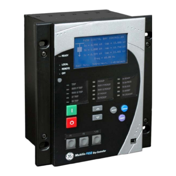
1.1 IMPORTANT PROCEDURES 1 GETTING STARTED 1.1IMPORTANT PROCEDURES Use this chapter for initial setup of your new F650 Feeder Protection Relay. 1.1.1 CAUTIONS AND WARNINGS To help ensure years of trouble free operation, please read through the following chapter for information to help guide you through the initial installation procedures of your new relay. - Page 8 This product is rated to Class A emissions levels and is to be used in Utility, Substation Industrial environments. Not to be used near electronic devices rated for Class B levels. Figure 1–1: FRONT VIEW OF F650 UNITS F650 Digital Bay Controller...
- Page 9 Check that the relay is fully operative. Figure 1–2: MODULE WITHDRAWAL/INSERTION GE Multilin will not be responsible for any damage of the relay, connected equipment or personnel whenever these safety rules are not followed.
- Page 10 It is very important, for safety reasons not to change or switch the terminals for CTs and VTs. Figure 1–3: REAR VIEW OF F650 UNIT will not be responsible for any damage of the relay, connected equipment or personnel GE Multilin whenever these safety rules are not followed.
-
Page 11: Inspection Checklist
Unwrap the relay and inspect the relay for physical damage. View the nameplate and verify that the correct model has been ordered and delivered. The model number is at the top. Figure 1–4: IDENTIFICATION LABEL (A4454P6) GEK-113000AE F650 Digital Bay Controller... - Page 12 Wiring diagram. • Certificate of Compliance For product information, instruction manual updates, and the latest software updates, please visit the GE Multilin Home Page: http://www.gegridsolutions.com/index.htm New Note: If there is any physical damage detected on the relay, or any of the contents listed are missing, please...
-
Page 13: Safety Instructions
Figure 1–5: LOCATION OF GROUNDING SCREW Before communicating with a F650 unit through the front USB port, please ensure that the computer's power supply is grounded. In case of using a laptop, it is recommended not to have it connected to its power supply. - Page 14 Before working on CTs, they must be short-circuited. • Do not remove the voltage terminal blocks or disconnect the voltage input wires when the voltage phases are live. The voltage inputs must be de-energized prior to any servicing. 1.1.3.2 WARNING SYMBOLS F650 Digital Bay Controller GEK-113000AE...
- Page 15 Earth (Ground) Terminal. Terminal de terre (masse). Protective Earth Terminal. Terminal de terre de protection. Note: Read all instructions included in package before using your product. Additional safety information Product Safety Supplement document available at; http://www.gegridsolutions.com/ProductSafety/ GEK-113000AE F650 Digital Bay Controller...
-
Page 16: Overview
1 GETTING STARTED 1.2OVERVIEW 1.2.1 INTRODUCTION TO 650 FAMILY OF RELAYS The GE 650 family relay is a new generation of digital and multifunction equipment that is easily incorporated into automation systems, at both the station and enterprise levels. 1.2.2 HARDWARE ARCHITECTURE... - Page 17 1 GETTING STARTED 1.2 OVERVIEW Figure 1–6: 650 CONCEPT BLOCK DIAGRAM b) F650 SIGNAL TYPE Contact Inputs/Outputs are digital signals. CT and VT inputs: are signals coming from the inputs of current and voltage transformers, used for monitoring the power system signals.
-
Page 18: Communications Architecture
CAN BUS I/Os. This fact provides increased communication speed, as well as the possibility of acknowledgement of modules, abnormalities, etc. As this is a serial port supporting a communications protocol, it provides extraordinary immunity against external or internal disturbances. 1-12 F650 Digital Bay Controller GEK-113000AE... - Page 19 PROTECTION CAN I/O INTERNAL SERIAL MULTIPLEXED SERIAL COM 2 COM H MEASUREMENT PROCESSOR ANALOG SERIAL INPUTS COM2 COM H CURENT AC FRONT VOLTAGE AC HUMAN MACHINE INTERFACE SERIAL PORT Figure 1–7: COMMUNICATIONS ARCHITECTURE (B6816F2) GEK-113000AE F650 Digital Bay Controller 1-13...
-
Page 20: Enervista 650 Setup Software
RS232C and USB serial and/or Ethernet port for communications to the relay. 1.3.2 INSTALLATION After ensuring the minimum requirements for using EnerVista 650 Setup are met (see previous section), install the software from the GE EnerVista DVD. Or download the 650 EnerVista software from http://www.gegridsolutions.com/multilin/ install it. - Page 21 Install Software window as shown below. Select the “Web” option to ensure the most recent software release, or select “CD” if you do not have a web connection, then click the Add Now button to list software items for the F650.
- Page 22 Click Next to begin the installation process, and all the necessary program files will be copied into the chosen directory. Figure 1–12: SELECT PROGRAM FOLDER 12. To finish with the installation process, select the desired language for startup. 1-16 F650 Digital Bay Controller GEK-113000AE...
-
Page 23: Connecting Enervista 650 Setup With F650
1.3 ENERVISTA 650 SETUP SOFTWARE Figure 1–13: LANGUAGE WINDOW 13. Click Finish to end the installation. The F650 device will be added to the list of installed IEDs in the EnerVista Launchpad window, as shown below. Figure 1–14: ENERVISTA LAUNCHPAD 1.3.3 CONNECTING ENERVISTA 650 SETUP WITH F650... - Page 24 Before starting, verify that the Ethernet network cable is properly connected to the Ethernet port on the back of the relay. Install and start the latest version of the EnerVista 650 Setup software (available from the GE EnerVista DVD or online from http://www.gegridsolutions.com/index.htm...
-
Page 25: Hardware
USB shielded wire is needed To communicate through the F650 rear RS485 port from a PC RS232 port, the GE Multilin RS232/RS485 converter box is required. This device (catalog number F485) connects to the computer using a “straight-through” serial cable. A shielded twisted-pair (20, 22 or 24 AWG according to American standards;... -
Page 26: Faceplate Display
Figure 1–16: RS485 CONNECTION FOR 650 UNITS To communicate through the F650 rear Ethernet port from a PC a crossover cable is required. If the connection is performed through a hub or a switch, a direct Ethernet cable is required. -
Page 27: Storage
1 GETTING STARTED 1.4 650 HARDWARE If it is concluded that the relay or one of its modules is of concern, contact GE Multilin or one of its representative for prompt service. 1.4.4.2 IN-SERVICE MAINTENANCE In-service maintenance: Visual verification of the analog values integrity such as voltage and current (in comparison to other devices on the corresponding system). -
Page 28: Repairs
1.4.7 DISPOSAL The F650 is intended to be part of defective large-scale stationary industrial tools and large-scale fixed installations. This product cannot be disposed of as unsorted municipal waste in the European Union. For proper recycling return this product to your supplier or a designated collection point. -
Page 29: Product Description
2.1 F650 OVERVIEW 2 PRODUCT DESCRIPTION 2.1 F650 OVERVIEW F650 is a protection, control, monitoring, metering and registering unit, suitable for many different applications, such as main protection for distribution feeders and transmission lines, as well as backup protection for transformers, busbars, capacitor banks, etc. -
Page 30: Ansi Device Numbers And Functions
Broken Conductor 81df/dt Frequency Rate of Change VTFF VT Fuse Failure Detection 60CTS Failure Current Transformer Failure ** 2nd Harmonic Second Harminic Inhibit ** Inhibit ** These functions are available for firmware version 7.50 or above F650 Digital Bay Controller GEK-113000AE... -
Page 31: Other Device Functions
Diagram (Graphic Snapshot Events (up to 1023)** Web Server Application model only) Phasor Diagram (available in EnerVista 650 Setup) ** Maximun number of events can vary depend on firmware version. See details in section 2.5.3.3 GEK-113000AE F650 Digital Bay Controller... -
Page 32: Ordering Code
2 PRODUCT DESCRIPTION 2.4 ORDERING CODE F650 units are supplied as ½ 19” rack, 6 units high, containing the following modules: power supply, CPU, I/O modules, communication modules. The required information to completely define an F650 model is shown on Table 2–1: Table 2–1: ORDERING CODE... - Page 33 (Remote CAN Bus I/O module) for using up to 2 additional boards. F650 units allow monitoring and configuring these I/O boards as if they were internal boards, located on slots F and G. In this case, slots are labeled as H y J.
- Page 34 (1) The digit selected for option J must be equal or higher than the digit selected for option H for models including boards 4 and 5. CIOH1J5**: is a valid selection CIOH5J1**: is an invalid selection F650 Digital Bay Controller GEK-113000AE...
-
Page 35: Technical Specifications
Timing accuracy Operate at > 1.03 times the pickup ±3% of operate time or 50 ms. (whichever is greater) Voltage restraint Selectable by setting Saturation Level 48 times the pickup level Snapshot Events Selectable by setting GEK-113000AE F650 Digital Bay Controller... - Page 36 Instantaneous or time delayed according to IEEE Timing accuracy Operate at > 1.03 times the pickup ±3% of operate time or 50 ms. (whichever is greater) Saturation Level 48 times the pickup level Snapshot Events Selectable by setting F650 Digital Bay Controller GEK-113000AE...
- Page 37 <50 ms at 3 x Pickup at 50 Hz, typically Timing accuracy at 0 ms time delay (no intentional delay): 50ms at non-zero time delay: ±3% of operate time or 50 ms (whichever is greater) Snapshot Events Selectable by setting GEK-113000AE F650 Digital Bay Controller...
- Page 38 <50 ms at 3 x Pickup at 50 Hz, typically Timing accuracy at 0 ms time delay (no intentional delay): 50ms at non-zero time delay: ±3% of operate time or 50 ms (whichever is greater) Snapshot Events Selectable by setting 2-10 F650 Digital Bay Controller GEK-113000AE...
- Page 39 Instantaneous or time delayed according to IEEE Timing accuracy Operate at > 1.03 times the pickup ±3% of operate time or 50 ms. (whichever is greater) Saturation Level 48 times the pickup level Snapshot Events Selectable by setting GEK-113000AE F650 Digital Bay Controller 2-11...
- Page 40 Polarizing Current threshold 0.005 A Characteristic angle -90º to +90º in steps of 1º Block Logic Permission or Block selectable by setting Angle accuracy ±3º for I>0.1 A and V>5 Vac Operate time <30ms, typically 2-12 F650 Digital Bay Controller GEK-113000AE...
- Page 41 Reset delay 0.00 to 900.00 s. in steps of 0.01 s. Timing accuracy ±3.5% of operate time or 50 ms. (whichever is greater) Logic Any/Two/All phases logic selectable by setting Snapshot Events Selectable by setting GEK-113000AE F650 Digital Bay Controller 2-13...
- Page 42 0.00 to 900.00 s. in steps of 0.01 s Reset delay 0.00 to 900.00 s. in steps of 0.01 s Timing accuracy ±3.5% of operate time or 50 ms. (whichever is greater) Snapshot Events Selectable by setting 2-14 F650 Digital Bay Controller GEK-113000AE...
- Page 43 0.00 to 900.00 s. in steps of 0.01 s Minimum voltage threshold 10 to 300V in steps of 1 V Time Delay Accuracy 0 to 7 cycles Operate time Typically 10 cycles at 0.1Hz/s change Snapshot Events Selectable by setting GEK-113000AE F650 Digital Bay Controller 2-15...
- Page 44 ±3.5% of operate time or 50 ms. (whichever is greater) Block Time after close 0.00 to 900.00 s in steps of 0.01 s Snapshot Events Selectable by setting Operate time: < 45 ms at 50 Hz, typically 2-16 F650 Digital Bay Controller GEK-113000AE...
-
Page 45: Control
0.00 to 900.00 s in steps of 0.01 s Reset time 0.00 to 900.00 s in steps of 0.01 s Snapshot Events Selectable by setting Possibility to modify protection settings after each shot programmable through PLC (block signals available after each shot) GEK-113000AE F650 Digital Bay Controller 2-17... - Page 46 ±0.5% of the reading ± 10 mA from 0.05 to 10 A ±1.5% of the reading for higher values. Timing accuracy ±3.5% of operate time or 50 ms. (whichever is greater) Snapshot Events Selectable by setting 2-18 F650 Digital Bay Controller GEK-113000AE...
- Page 47 Phasor (without harmonics) or RMS Rated current For connection to 1 or 5 A CTs. Full Load Current 0.10 to 10.00 kA in steps of 0.01 kA Pickup level 1.01 to 109.00 in steps of 0.01 x FLC GEK-113000AE F650 Digital Bay Controller 2-19...
- Page 48 -100000.000 to 100000.000 in steps of 0.001 Analog Delay 0.00 to 900.00 in steps of 0.01 Analog Hysteresis 0.0 to 50.00 in steps of 0.1 Analog Direction (for activation inside or outside the IN or OUT deadband) 2-20 F650 Digital Bay Controller GEK-113000AE...
- Page 49 0.03 to 0.25 s in steps of 0.01 s t integration Time Maximum openings 0 to 9999 in steps of 1 Maximum Openings in one hour 1 to 60 in steps of 1 Snapshot Events Selectable by setting GEK-113000AE F650 Digital Bay Controller 2-21...
- Page 50 Name Any 12 alphanumeric characters Preset -2147483648, 0, +2147483647 COMPARE -2147483648, 0, +2147483647 2.5.2.18 COLD LOAD PICKUP Cold Outage time 1 -1000 in steps of 1min Cold Blocking time 1-1000 in steps of 1s 2-22 F650 Digital Bay Controller GEK-113000AE...
-
Page 51: Monitoring
1023 scrolling events 1 ms using an internal clock of 100 μs Time-tag Timing Accuracy: 1 ms (using the IRIG-B synchronization input) Triggers: Any element pickup, dropout or operation Digital input /output change of state GEK-113000AE F650 Digital Bay Controller 2-23... - Page 52 Selectable by setting 2.5.3.6 DATA LOGGER Number of Channels: 1 to 16 Parameters Any available analog actual value Samples 1 sec., 1, 5, 10, 15, 20, 30, 60 min. Storage Capacity Fixed, 32768 measures 2-24 F650 Digital Bay Controller GEK-113000AE...
-
Page 53: User-Programmable Elements
The following 10 ones (yellow and green) are self-reset but can be latched through PLC configuration. The LED’s can be reset by hardware, pressing the front “esc” key during more Reset Signal: than 3 seconds or using the LED reset signal through PLC configuration. GEK-113000AE F650 Digital Bay Controller 2-25... -
Page 54: Metering
±2.0% of the reading at-0.2 ≤ PF ≤ 0.2 2.5.5.5 APPARENT POWER (VA) Accuracy: ±2.0% of the reading 2.5.5.6 WATT-HOURS (POSITIVE AND NEGATIVE) Accuracy: ±2.0% of the reading Range: -2147483 to +2147483 MWh Parameters: 3-phase only Update rate: 100 ms 2-26 F650 Digital Bay Controller GEK-113000AE... -
Page 55: Inputs
2.5.6.1 AC CURRENT INPUTS CT Ratio: 1.0 to 6000.0 in steps of 0.1 Rated currents: Appropriate for 1 or 5 A. F650 has universal range for CT (valid for 1 or 5 A to only one terminal). Relay Burden: <0.2 VA... - Page 56 0 to -1; 0 to +1; -1 to +1; 0 to 5; 0 to 10; 0 to 20; 4 to 20 (programmable) Conversion Range: -1 to +20mA Accuracy: ±0.2% of full scale Type: Passive 2-28 F650 Digital Bay Controller GEK-113000AE...
-
Page 57: Real Time Clock
If the current in the tripping circuit is maintained over 500 mA, the function is sealed independently of the status of the function that caused the trip. 2.5.8.1 REMOTE OUTPUTS (IEC61850 GSSE/GOOSE) Standard output points User output points GEK-113000AE F650 Digital Bay Controller 2-29... -
Page 58: Control Power Supply
Optic Features for ST connectors devices: Wave length: 1300nm Fiber type: multimode 62.5/125 μm or 50/125 μm Baud Rate: 300, 600, 1200, 2400, 4800, 9600, 19200, 38400, 57600 y 115200 bauds Default Baud Rate 19200 2-30 F650 Digital Bay Controller GEK-113000AE... - Page 59 Two witness LED’s for transmission and reception are included SIMPLE NETWORK TIME PROTOCOL (SNTP) Clock synchronization error: <10 ms (typical) PRECISION TIME PROTOCOL (PTP) PTP IEEE Std 1588 2008 (version 2) Power Profile (PP) per IEEE Standard PC37.238TM2011 Slave-only ordinary clock GEK-113000AE F650 Digital Bay Controller 2-31...
- Page 60 PARALLEL REDUNDANCY PROTOCOL (HSR) (IEC 62439-3 CLAUSE 5, 2012) Ethernet ports used A and B Networks supported 10/100 MB Ethernet RAPID SPANNING TREE PROTOCOL (RSTP) (IEC 62439-1, IEEE 801.2D) Ethernet ports used A and B Networks supported 10/100 MB Ethernet 2-32 F650 Digital Bay Controller GEK-113000AE...
-
Page 61: Optic Features
At the Beginning of Life (BOL). Over the specified operating temperature and voltage ranges. All conditions for Note 3 apply except that the measurement is made at the center of the symbol with no window time- width. GEK-113000AE F650 Digital Bay Controller 2-33... -
Page 62: Environmental Characteristics
Dry heat test (operational) IEC60068-2-2 60˚C 16 hrs Change of Temperature IEC60068-2-14 5 cycles (3+3) -20˚C/60˚C Damp Heat Humidity Cyclic IEC60068-2-30 6 cycles (12+12) 55˚C @ 93% R.H. Damp Heat steady state IEC60068-2-78 40˚C @ 93% R.H. 2-34 F650 Digital Bay Controller GEK-113000AE... -
Page 63: Approvals
2.5 TECHNICAL SPECIFICATIONS Type test report available upon request. F650 has been designed to comply with the highest existing requirements. More specifically, UNIPEDE recommendations for high voltage substations are followed, even if for most applications such high classes are not required. -
Page 64: External Connections
2.6 EXTERNAL CONNECTIONS 2 PRODUCT DESCRIPTION 2.6EXTERNAL CONNECTIONS Figure 2–2: F650 WIRING DIAGRAM (189C4216H2) 2-36 F650 Digital Bay Controller GEK-113000AE... - Page 65 79 INITIATE I SENS RECLOSE F14 + CC8 F15 + COIL 2 52/a SUPERVISION TRIP F17 + COIL 2 52/b SUPERVISION F18 - 52/b Figure 2–3: INPUT/OUTPUT CONFIGURATIONS FOR BOARDS F1 AND F2 (189C4216H1) GEK-113000AE F650 Digital Bay Controller 2-37...
- Page 66 2.6 EXTERNAL CONNECTIONS 2 PRODUCT DESCRIPTION 2-38 F650 Digital Bay Controller GEK-113000AE...
-
Page 67: Human Interfaces
3.1.2 ENERVISTA 650 SETUP SOFTWARE OVERVIEW This software package uses ModBus protocol, and it is designed to communicate with a single relay at a time. GE offers different communication software packages, such as GE-POWER, which can be used to communicate simultaneously with several relays. - Page 68 3.1.2.5 FIRMWARE UPGRADES The firmware of a F650 device can be upgraded, locally or remotely, via the EnerVista 650 Setup software.The corresponding instructions are provided on the Chapter 9 on this instruction manual, “BOOTCODE AND FIRMWARE UPGRADE”.
-
Page 69: Main Screen
The EnerVista 650 Setup software main window supports the following primary display components: • Title bar • Main menu bar • Main icon bar • Working area • Status bar Title Working Area Figure 3–1: ENERVISTA 650 SETUP MAIN SCREEN GEK-106310AE F650 Digital Bay Controller... -
Page 70: Communication Menu
Modbus/TCP Setup (if ModBus /TCP is selected as control type): Communication parameters for ModBus TCP communication. • Communication control: Device communication status (communicating or not communicating). • Communication optimization: allows optimizing the communication time outs and failure establishing. F650 Digital Bay Controller GEK-106310AE... - Page 71 EnerVista 650 Setup. These parameters are the maximum time to wait for a response in the relay (in ms) and the maximum attempts to perform before assuming communications failure. GEK-106310AE F650 Digital Bay Controller...
-
Page 72: File Management
*.650 for further logic changes. Figure 3–3: OFF-LINE MODE FILE MANAGEMENT 1.Note: “Relay and logic configuration” and “Protection and Control Settings” are required to be uploaded to the F650 relay in order for the device to operate properly F650 Digital Bay Controller GEK-106310AE... - Page 73 *.pep in the relay, the associated *.aut and *.lib files are also stored. File storage inside the relay "Communication > Upload info files to relay" through Ethernet (RECOMMENDED) Retrieval of files stored in the relay "Communication > Download info files from relay" through Ethernet (RECOMMENDED) GEK-106310AE F650 Digital Bay Controller...
- Page 74 Save all settings & configuration (“File>Get info from relay”) Store in the relay the Logic configuration files (*.pep, *.aut, *.lib) as well as the *.650 for further logic changes. (“Communication>Upload info files to relay”) Figure 3–4: ON LINE MODE FILE MANAGEMENT F650 Digital Bay Controller GEK-106310AE...
- Page 75 Logic programming support files (*.pep, *.aut, *.lib) CANNOT be retrieved directly from the relay. It is necessary * Either to have stored these files in the PC * Or to have uploaded previously the files into the relay ("Communication>Upload info files to relay") GEK-106310AE F650 Digital Bay Controller...
-
Page 76: Enervista 650 Setup Menu Structure
Clock (*) relay Send info Download info files to relay (*) from relay Print Setup (**) Print Preview (**) Print (**) Print to file Checksum calculation (**) Checksum calculation Settings checksum calculation Order code Exit 3-10 F650 Digital Bay Controller GEK-106310AE... -
Page 77: File Menu Overview
Setting CRC and the actual value of the Setting Calculation CRC read from the relay must match). Option available for F650 with firmware version 7.00 or above. It allows customers to get special functionality model (see model selection) with Order code(*) password requirements. - Page 78 "Close" option, a new *.650 can be opened without closing the previous one. The "Close" option is used to clear all data in EnerVista 650 Setup program, enabling "Language", "Upgrade firmware version" and "Upgrade Operating system" options. 3-12 F650 Digital Bay Controller GEK-106310AE...
- Page 79 After source file selection, new pop-up window will be displayed to allow selecting destination model. Different sections can be distinguished in this new window: Source Model: It indicates source F650 model and original version of selected file. Destination model: Drop-down list where available F650 models and firmware versions are listed.
- Page 80 Curve Definite time Definite time Definite time TD Multiplier 0,02 0,05 Reset** INSTAN INSTAN INSTAN Voltage Restraint** DISABLED DISABLED DISABLED Snapshot Events** ENABLED ENABLED ENABLED ** Note that fields in grey contain default values. 3-14 F650 Digital Bay Controller GEK-106310AE...
- Page 81 2,00 1,00 1,00 Definite IEEE IEEE Ext Curve Definite time Definite time IEEE Ext Inv time Ext Inv TD Multiplier 0,02 1,00 0,05 1,00 0,10 1,00 Reset INSTANTANEOUS Voltage DISABLED Restraint Snapshot ENABLED Events GEK-106310AE F650 Digital Bay Controller 3-15...
- Page 82 When this option is selected, the program will show a screen including the relay model information, firmware version, etc. of the file being edited, as shown on Figure 3–8: Figure 3–8: FILE PROPERTIES MENU 3-16 F650 Digital Bay Controller GEK-106310AE...
- Page 83 PRINT TO FILE (*XLS) Possibility to export the configuration file to an Excel file using the "Print to file (*.xls)" option. GEK-106310AE F650 Digital Bay Controller 3-17...
- Page 84 Configuration available in file and located in Enervista 650 Setup at Setpoint>Relay configuration excluding: ◦ Configuration available in HMI tab ◦ All texts configured in that section ◦ Opening and closing time located at Switchgear section 3-18 F650 Digital Bay Controller GEK-106310AE...
- Page 85 Enervista Setup Setpoint>Product Setup>Communication settings> SerialPorts or Network(Ethernet) or Modbus Protocol or Routing ◦ Relay calibration factors • Opening and closing time located at Switchgear section at Setpoint> Relay Configuration in Enervista 650 Setup GEK-106310AE F650 Digital Bay Controller 3-19...
-
Page 86: Setpoint Menu Overview
Demand settings. The demand trigger and demand reset signals must be Demand configured in "Setpoint>Relay configuration" Time Settings Time settings. Options enabled only in On-line mode are marked as (*). Options enabled only in Off-line mode are marked as (**) 3-20 F650 Digital Bay Controller GEK-106310AE... - Page 87 3 HUMAN INTERFACES. SETTINGS & ACTUAL VALUES 3.1 ENERVISTA 650 SETUP SOFTWARE INTERFACE a) COMMUNICATION SETTINGS This section details the settings related to communication parameters for the different protocols available in the F650. Table 3.7: GENERAL OVERVIEW OF COMMUNICATION SETTINGS MENU:...
- Page 88 Table 3.9: GENERAL OVERVIEW OF BREAKER MENU Breaker settings, maintenance and switchgear selection of the device configured as breaker in the F650. The selected switchgear will be used Breaker settings in recloser, breaker failure and synchronism functions. The settings are Number of Switchgear, Maximum KI2t, KI2t Integ.
- Page 89 Wattmetric ground fault low (32N Low), in secondary values These menus will be available under setting group menus for relays with firmware version 7.50 or above. For firmware version below 7.5, these menus will be located directly under Protection Element menu. GEK-106310AE F650 Digital Bay Controller 3-23...
- Page 90 Table 3.13: GENERAL OVERVIEW OF CONTROL ELEMENTS MENU FOR FIRMWARE VERSION BELOW 7.50 CONTROL ELEMENTS F650 units incorporate a flexible grouping capability for protection units. This means that protection units can be used in either single setting group (default mode-all units can operate simultaneously) or three setting groups (in this mode, protection units are grouped in three independent tables, with only one of them active at a given time).
- Page 91 Section that contains the settings for all input and output boards and the Force Outputs and Virtual inputs activation tools. Table 3.15: GENERAL OVERVIEW OF “INPUTS/OUTPUTS” SETTINGS MENU. INPUTS/ OUTPUTS Inputs and outputs settings for all boards in F650. The I/O settings Contact I/O configuration can only be performed through EnerVista 650 Setup, not HMI available.
- Page 92 3.1 ENERVISTA 650 SETUP SOFTWARE INTERFACE 3 HUMAN INTERFACES. SETTINGS & ACTUAL VALUES This section shows the settings related to inputs and outputs for the different boards available in F650 (F, G, H, J). Table 3.16: GENERAL OVERVIEW OF “INPUTS/OUTPUTS>CONTACT I/O” SETTINGS MENU.
- Page 93 Machine Interface) etc. The menu includes a library for power elements, metering elements, text and drawings. See an example on the next page. GEK-106310AE F650 Digital Bay Controller 3-27...
- Page 94 3.1 ENERVISTA 650 SETUP SOFTWARE INTERFACE 3 HUMAN INTERFACES. SETTINGS & ACTUAL VALUES The following figures show an example of the default factory configuration for F650: Figure 3–12: RELAY CONFIGURATION Figure 3–13: HMI CONFIGURATION 3-28 F650 Digital Bay Controller GEK-106310AE...
- Page 95 *.lib:User programmable logic objects: Library file to be included as an object in a PLC project. Logic packages that can be stored into libraries and be distributed in different PLC projects. 3.1.8.10 IEC103 CONFIGURATION This menu allows to update the IEC 103 configuration of the unit. Figure 3–14: IEC103 CONFIGURATOR See chapter 5.13 GEK-106310AE F650 Digital Bay Controller 3-29...
- Page 96 3.1 ENERVISTA 650 SETUP SOFTWARE INTERFACE 3 HUMAN INTERFACES. SETTINGS & ACTUAL VALUES 3.1.8.11 CLOCK This menu allows to update the date and time of the relay, either synchronizing them with the PC clock, or entering the information manually. Figure 3–15: CLOCK 3-30 F650 Digital Bay Controller GEK-106310AE...
-
Page 97: Actual Values Menu Overview
Fault reports, control events, oscillography, data logger, demand, energy, and breaker maintenance. SNTP-IRIG_B & PTP Information related to synchronization via IRIG_B, SNTP or PTP1588. 1588 Information related to the different firmware versions and hardware Versions revisions. GEK-106310AE F650 Digital Bay Controller 3-31... - Page 98 Status signals (pickups and operations) for load encroachment units. Max.Number of Starts Status signal for number of starts operations Digital Counters Status signals for the Digital Counter units. Cold Load Pickup Status signals for the Cold Load Pickup Function. 3-32 F650 Digital Bay Controller GEK-106310AE...
- Page 99 Demand trigger and reset inputs status. Energy Freeze, unfreeze and reset input signals for energy counters. Breaker Maintenance All signals related to breaker maintenance, such as number of openings, closings, (KI) t counters, alarm signal for (KI) t, etc. GEK-106310AE F650 Digital Bay Controller 3-33...
- Page 100 Retrieval and visualization of fault report files, by Ethernet. Data logger (*) Retrieval and visualization of data logger files. Only by Ethernet. Options enabled only in On-line mode are marked as (*). Options enabled only in Off-line mode are marked as (**) 3-34 F650 Digital Bay Controller GEK-106310AE...
-
Page 101: Operations Menu Overview
Troubleshooting (Serial or Ethernet connection): Lets the user to perform reading or writing in ModBus addresses, for verifying communications and access to different positions in the ModBus memory map. Only available if the communication has already been established. Go to "Communication>Troubleshooting". An example is provided in Figure 3–16: GEK-106310AE F650 Digital Bay Controller 3-35... - Page 102 Ethernet communication. Firmware is related to the relay internal program, designed by GE Multilin, which performs the protection and control functions, and which is run by the relay main microprocessor.
- Page 103 "Communications>Upload/Download info files to relay", stores/retrieves in the relay hard disk: settings, configuration and compiled logic equations (*.650) besides the PLC files (*.pep, *.aut, *.lib). This is only a physical storage (file backup). GEK-106310AE F650 Digital Bay Controller 3-37...
-
Page 104: Security Menu Overview
Table 3.31: GENERAL OVERVIEW OF HELP MENU: HELP Instructions Manual Instructions manual in the language selected in "View>Languages" menu. GE Mulitlin on the Web GE Multilin web page link. About EnerVista 650 Release version and date of EnerVista 650 Setup program. Setup... -
Page 105: Human Machine Interface (Hmi)
There is also a removable dust cover that fits over the display and other cover that protects the front RS232 Communications port and the commands buttons that can be sealed. The following figure shows the HMI in F650 HMI Interface DISPLAY &... -
Page 106: Display
3.2.1 DISPLAY F650 units are available with two different options for the front display. The first option is an alphanumerical display of 4 lines with 20 characters each, and the second option is a graphical display of 16 lines with 40 characters each (128x240 pixels). -
Page 107: Front Led Indicators
Press or rotate the shuttle key to enter the text main menu from the text standby screen. Figure 3–20: KEYPAD AND SHUTTLE KEY DESCRIPTION FOR NON-ENHANCED DISPLAY MODELS GEK-106310AE F650 Digital Bay Controller 3-41... - Page 108 Enter Key. Press key to enter to submenus or to change values. Escape key. Press key to exit from menus Reset key. When pressed it will test all LEDs and reset the trip LEDs. Figure 3–21: ENHANCED KEYPAD DESCRIPTION 3-42 F650 Digital Bay Controller GEK-106310AE...
-
Page 109: Front Port And Cover Sealing System
Cover sealing system Screen contrast regulator Electrically isolated RS232 port Local/remote Operations access Figure 3–22: DETAIL OF FRONT PORT AND COVER SEALING SYSTEM GEK-106310AE F650 Digital Bay Controller 3-43... -
Page 110: Screen Contrast
When rotating the shuttle keys (or up/down keys) the selected menu is marked by a single scroll bar character. The mark (>) in the right part of any menu means that contains more than one level. Figure 3–23: Shows an example of main menu navigation: Figure 3–23: NAVIGATION IN MAIN TEXT MENU 3-44 F650 Digital Bay Controller GEK-106310AE... - Page 111 English. Press shuttle key or enter key to confirm selection. Switch the relay off and on. < - return Return to previous level Press shuttle key or enter key to return to previous level. GEK-106310AE F650 Digital Bay Controller 3-45...
- Page 112 Digital Counters Cold Load Pickup Switchgear Status > Switchgear 1 Switchgear... Switchgear 16 Calibration Flex Curves System Info Records Status > Fault Reports Control Events Oscillography Data logger Demand Energy Breaker Maintenan. SNTP-IRIG_B-PTP Versions Redundancy 3-46 F650 Digital Bay Controller GEK-106310AE...
- Page 113 ESC key to return to previous level if desired. This navigation will be performed the same for all the menus in Actual Values. Once the last sublevel is reached, move up and down to visualize the actual values selected. GEK-106310AE F650 Digital Bay Controller 3-47...
- Page 114 Figure 3–24: ACTUAL VALUES SCREEN DATA In the Actual Values menus are different types of data, each type of data will display its particular status type (on and off, 0 or 1, ok or fail, analog values, etc.) 3-48 F650 Digital Bay Controller GEK-106310AE...
- Page 115 Pressing the enter/shuttle key the metering screen for the snapshot event will be displayed. To exit from this screen press the ESC key and return to the snapshot events menu. Figure 3–25: SNAPSHOT EVENTS NAVIGATION IN HMI GEK-106310AE F650 Digital Bay Controller 3-49...
- Page 116 Fault reset, and they can be obtained from the relay using EnerVista 650 Setup software, at the "Actual>Records>Fault report" menu. If there is no fault report available through the display, the relay will show a "Fault report not available" message. 3-50 F650 Digital Bay Controller GEK-106310AE...
- Page 117 CAG phase CAG to ground PHASE Phase to phase faults phase A to phase B phase B to phase C phase C to phase A 3PHASE Three-phase faults (shown on the display as 3PH) Fault type not calculated GEK-106310AE F650 Digital Bay Controller 3-51...
- Page 118 Phase TOC High 2 Phase TOC High 3 Phase TOC Low > Phase TOC Low 1 Phase TOC Low 2 Phase TOC Low 3 Phase IOC High > Phase IOC High 1 Phase IOC High 2 3-52 F650 Digital Bay Controller GEK-106310AE...
- Page 119 Sens. Ground TOC 3 Sens. Ground IOC > Sens. Ground IOC 1 Sens. Ground IOC 2 Sens. Ground IOC 3 Isolated Gnd IOC > Isolated Gnd IOC 1 Isolated Gnd IOC 2 Isolated Gnd IOC 3 GEK-106310AE F650 Digital Bay Controller 3-53...
- Page 120 Directional Power 1 Directional Power 2 Directional Power 3 Watt Gnd Flt High > Watt Gnd Flt High 1 Watt Gnd Flt High 2 Watt Gnd Flt High 3 Watt Gnd Flt Low > 3-54 F650 Digital Bay Controller GEK-106310AE...
- Page 121 Load Encroachment 1 Load Encroachment 2 Load Encroachment 3 Max. Num of starts Cold Load Pickup PLC Timer Masks (*) This menu changes as indicated in table 4.35 for firmware version 7.50 or above. GEK-106310AE F650 Digital Bay Controller 3-55...
- Page 122 > Neutral TOC 1 Neutral TOC 2 Neutral TOC 3 Neutral IOC > Neutral IOC 1 Neutral IOC 2 Neutral IOC 3 Neutral Dir > Neutral Dir 1 Neutral Dir 2 Neutral Dir 3 3-56 F650 Digital Bay Controller GEK-106310AE...
- Page 123 Neg. Seq. TOC 1 Neg. Seq. TOC 2 Neg. Seq. TOC 3 Voltage Elements > Phase UV > Phase UV 1 Phase UV 2 Phase UV 3 Phase OV > Phase OV 1 Phase OV 2 GEK-106310AE F650 Digital Bay Controller 3-57...
- Page 124 Watt Gnd Flt High 2 Watt Gnd Flt High 3 Watt Gnd Flt Low > Watt Gnd Flt Low 1 Watt Gnd Flt Low 2 Watt Gnd Flt Low 3 Frequency > Underfrequency > Underfrequency 1 Underfrequency 2 3-58 F650 Digital Bay Controller GEK-106310AE...
- Page 125 Load Encroachment 2 Load Encroachment 3 Control Elements > Setting Group Synchrocheck Autoreclose Breaker Failure VT Fuse Failure. Max. Num of starts Cold Load Pickup PLC Timer Masks 60 CTS Failure 2nd HRMC Inhibit GEK-106310AE F650 Digital Bay Controller 3-59...
- Page 126 Once all settings inside the group have been modified, go to the last screen pressing the down key or rotating the shuttle key and press Enter. At this moment of time, the new settings will be active in the relay. Figure 3–27: CHANGE SETTINGS PROCEDURE IN HMI 3-60 F650 Digital Bay Controller GEK-106310AE...
- Page 127 Once this sequence is completed, these values will remain stored in the relay, and the display will show again the date at the bottom of the text screen. Figure 3–28: CHANGE DATE AND TIME PROCEDURE IN HMI GEK-106310AE F650 Digital Bay Controller 3-61...
- Page 128 Once the commands has been performed or the time out has expired the "Command completed" message will appear in the display. Figure 3–29: COMMANDS IN HMI 3-62 F650 Digital Bay Controller GEK-106310AE...
- Page 129 3 HUMAN INTERFACES. SETTINGS & ACTUAL VALUES 3.2 HUMAN MACHINE INTERFACE (HMI) 3.2.6.10 PASSWORDS F650 units incorporate independent passwords for protection and control, in order to prevent unauthorized keypad and display access to the relay. Settings Password: This password allows restricting access to settings changes in the relay protection elements.
- Page 130 Cod Settings: [35c0] Cod Commands: [35c0] <Push Enter> In order to obtain the decoded password from the encrypted codes provided by the relay, it is necessary to contact GE Multilin and provide these encrypted codes. 3-64 F650 Digital Bay Controller...
- Page 131 Ia 0.000 Vab 0.000 Ib 0.000 Vbc 0.000 Ic 0.000 Vca 0.000 Ig 0.000 0.000 Figure 3–31: DEFAULT METERING SCREEN This option alternates in time the two previous options. GEK-106310AE F650 Digital Bay Controller 3-65...
- Page 132 Once the new language has been selected it is necessary to reboot the relay in order to start working with the new language in the device. Figure 3–32: LANGUAGE SELECTION IN HMI 3-66 F650 Digital Bay Controller GEK-106310AE...
-
Page 133: Graphic Display
In models with graphic display default main screen is the single-line diagram. This single-line diagram can be configured using EnerVista 650 Setup software by choosing the HMI menu inside Relay Configuration (Setpoint>Relay Configuration>HMI). F650 DIGITAL BAY CONTROLLER Ia = 0.000 kA Vab =0.000 kV Ib = 0.000 kA... - Page 134 Phase A Power Factor Negative MWatthour I0 Primary VBB Primary Phase B Power Factor % of Load-to-trip I1 Primary Phase A Reactive Pwr Phase C Power Factor I2 Primary Phase A Apparent Pwr 3 Phase Power Factor 3-68 F650 Digital Bay Controller GEK-106310AE...
- Page 135 The user accesses the next available graphic screen (Events – New) <PREV> This option returns to the general events graphic menu (All Events) <RELOAD> This option updates all events stored in the relay and returns to the general events screen. GEK-106310AE F650 Digital Bay Controller 3-69...
- Page 136 ESC: Prev. If the user presses the ESC key from the event detail screen, the system will return to the all events screen. 3-70 F650 Digital Bay Controller GEK-106310AE...
- Page 137 After the new events have been read, if the user selects again the Reload menu, the system will show a <No new events available.> message, indicating that there are no more new events available since the last reading. GEK-106310AE F650 Digital Bay Controller 3-71...
- Page 138 3 HUMAN INTERFACES. SETTINGS & ACTUAL VALUES 3.2.7.5 ALARMS PANEL Alarms panel can be viewed in all F650 models using communication software EnerVista 650 Setup, however, only models with graphic display allow access to the alarms panel from the HMI.
- Page 139 The selected option will be displayed in upper case and between brackets. To access the selected option, the enter/shuttle key must be pressed. GEK-106310AE F650 Digital Bay Controller 3-73...
- Page 140 When the shuttle key is pressed, the selected input will be activated. Navigation through this screen is indicated by the following legend: Esc: Exit Text. Enter: Chg Input. 3-74 F650 Digital Bay Controller GEK-106310AE...
- Page 141 Pressing the enter/shuttle key on the blinking output, this output will be activated in emulation mode. Note: Output emulation can be executed through the TEST OUTPUT tool on the graphic display, and also through communications using EnerVista 650 Setup software for all F650 models. : Chg Card Pressing the up-down key or rotating the shuttle key allows to change the selected I/O board in the main I/O screen.
-
Page 142: Web Server 3.3.1 Home
IP address, which must be configured in Setpoint > Product Setup > Communication Settings > Ethernet. The main screen of the F650 web server shows the different monitoring possibilities for snapshot events, events, alarms, oscillography, fault reports, data logger and metering values provided by the relay through the web. -
Page 143: Snapshot Events
The bottom of the screen shows a Metering screen; clicking on one of the events, the associated metering values will be shown on that screen. Figure 3–41: SNAPSHOT EVENTS SCREEN GEK-106310AE F650 Digital Bay Controller 3-77... -
Page 144: Control Events
Unlike the case of Snapshot events, in this screen the highest index corresponds to the most recent event. The information provided is the control event index, the text that has been associated to such event when configured, its status, active (ON) or inactive (OFF), and its date and time. 3-78 F650 Digital Bay Controller GEK-106310AE... -
Page 145: Alarms
The alarms screen provides access to alarms configured in the relay. As in the case of snapshot events and control events, this screen allows only to view the alarms, but not to acknowledge them. Figure 3–43: ALARMS SCREEN GEK-106310AE F650 Digital Bay Controller 3-79... -
Page 146: Oscillography
Download button. The system will then open a window to allow saving the files in Comtrade format in the PC hard drive. Once the records have been saved, the system will ask if the user wants to open GE-OSC tool (Comtrade record viewer) to view the downloaded files. -
Page 147: Fault Report
To obtain a text file with all the fault report information, press the Download option and save the file in the computer. GEK-106310AE F650 Digital Bay Controller 3-81... -
Page 148: Data Logger
The data logger screen allows viewing the data logger first and last value retrieval date and allows downloading the data record files in Comtrade format, by pressing the Download option. Stored files can be viewed later using any Comtrade format viewer Figure 3–47: DATA LOGGER SCREEN 3-82 F650 Digital Bay Controller GEK-106310AE... -
Page 149: Security
When this box is checked, the user will have the ability to upgrade firmware, bootware and to upload and Upgrade download info files to/from relay. By default, Administrator and Service users are created with "password" as default password. GEK-113000AE F650 Digital Bay Controller... -
Page 150: Changing Passwords
There is a limit of 50 characters available to enter the personal question. One example, as in the above diagram, would be "What is my mother's maiden name?". This question will be posed to the user if the user forgets their password and would like to know what their password was. F650 Digital Bay Controller GEK-113000AE... -
Page 151: Enabling Security
Security Control is enabled by checking the ENABLE SECURITY check box. The first time the enable security option is selected is necessary to close and open EnerVista 650 Setup to start working under security management. GEK-113000AE F650 Digital Bay Controller... -
Page 152: Loging Into Enervista 650 Setup
In case a user has forgotten about the log in password, the Forgot Password function can be used to retrieve the password. Figure 4–4: FORGOT YOUR PASSWORD? A question, which is pre-set by the user, will be asked. The password will be retrieved for entering the right answer. F650 Digital Bay Controller GEK-113000AE... -
Page 153: Bootcode And Firmware Upgrade
A STEP LIST SUMMARY that will allow the user to control the upgrading process is included at the end of this section. It is necessary to read paragraphs 1 to 4 of chapter 9 of manual GEK-106310 before accomplishing the F650 UPGRADE PROCEDURE. -
Page 154: Communication Parameters
PC IP Address - In case the boot code has been previously updated to the relay (section 9.2), the IP address and other parameters already assigned in the process will be: IP Address:192.168.37.177 Netmask:255.255.255.0 Gateway:192.168.37.10 Then the PC settings should be the same pattern as follows: F650 Digital Bay Controller GEK-113000AE... -
Page 155: Bootware Version Upgrade
USB-to-Serial Cable Converters existing nowadays in the market, with different characteristics, even different charge imposed to the USB bus of the PC, it is strongly recommended to use the GE USB-to-Serial RS232 Cable Converter, part number GE0100-0001. - Page 156 PC Figure 5–3: BOOT CODE FILE SELECTION Choose the bootware file and click Open button. The next screen will pop up: Figure 5–4: UPGRADE SELECTED BOOT FILE F650 Digital Bay Controller GEK-113000AE...
- Page 157 COM port to be used during upgrading. Figure 5–7: SET RELAY IP ADDRESS 11. .During the upgrade, the system will show the following message indicating the procedure to be followed. GEK-113000AE F650 Digital Bay Controller...
- Page 158 IP address that is going to be used lately in the relay for Ethernet connection. Figure 5–10: SETTING ADDRESS 13. After entering the temporary IP Address, the next new window will require the bootware file retrieved from http://www.gegridsolutions.com/index.htm and previously stored someplace in the PC. F650 Digital Bay Controller GEK-113000AE...
- Page 159 Figure 5–12: LOADING BOOT CODE FILE 15. Then the program shows a message requiring switch OFF and ON the relay while the progress bar is in course, to start the upgrading process. Figure 5–13: RELAY SWITCH OFF-ON MESSAGE GEK-113000AE F650 Digital Bay Controller...
- Page 160 17. After switching the relay OFF and ON, if the serial communication between EnerVista 650 Setup and the relay is correct the program shows the following message (Figure 5–13:): Figure 5–15: CONFIGURATION PROCESS IN PROGRESS Then it requires the confirmation to proceed to upgrade: F650 Digital Bay Controller GEK-113000AE...
- Page 161 Figure 5–17: FLASH MEMORY ERASE PROGRESS BAR 19. If the process is successful, continue with step 20 hereafter. If not and the relay gets stuck during at “Sending file imagen_kernel…” (see figure below) Figure 5–18: DOWNLOAD PROCESS ADVISORY GEK-113000AE F650 Digital Bay Controller...
- Page 162 21. After assigned the Ethernet parameters, the upgrade of the boot code will be completed successfully (figure below). 22. New momentarily window will display: "Setting Default IP address”, and then it follows with: Figure 5–20: BOOTWARE UPGRADE SUCCESSFUL PROCESS After boot code upgrade, the equipment firmware must also be upgraded (hereafter). 5-10 F650 Digital Bay Controller GEK-113000AE...
-
Page 163: Firmware Version Upgrade
The relay settings and configuration will be lost, so it is advisable to save them to a file. 2. For firmware revisions lower than 1.50, it is required to save calibration settings in a file before upgrading the F650 to a new firmware version. - Page 164 Select "Device FW Upgrade. FW version <7.00" option an click on [...]. A pop up window will come up to allow users to select the file Figure 5–22: SELECT FIRWARE FILE Click the “Upgrade File” button to continue. Figure 5–23: UPGRADE FIRMWARE SELECTED FILE 5-12 F650 Digital Bay Controller GEK-113000AE...
- Page 165 In versions 1.70 and higher it is also necessary to enter the ordering code for the relay. See figure below. If the relay is not an enhanced model or control functionality then click the Upgrade Firmware button to continue the process (figure below). Figure 5–25: FIRMWARE UPGRADE ACCEPTANCE WINDOW GEK-113000AE F650 Digital Bay Controller 5-13...
- Page 166 Now the Local Network status will be shown as Disabled.In the same screen with Right mouse key over LOCAL NETWORK click Enable and wait until Enabled status is shown. Then press Upgrade Firmware button to continue the process (figure below). 5-14 F650 Digital Bay Controller GEK-113000AE...
- Page 167 Figure 5–27: ADVISORY FOR LOCAL NETWORK REBOOT When upgrading models with Enhanced protection or control functionality (see model selection), the program will request a password to continue (figure below) Figure 5–28: RELAY REBOOT STEP GEK-113000AE F650 Digital Bay Controller 5-15...
- Page 168 ("upgrade.txt"). Wherever from this Upgrade.txt file would be obtained (http://www.gegridsolutions.com/index.htm from TS Dept. at any GE Multilin facility), then it must be saved in some directory in the root drive or in the desktop of the PC. Figure 5–30: FIRMWARE FILE ACCEPTANCE If the files are downloaded from the web, they are compressed in a zip file.
- Page 169 In case non-correct option is selected, metering errors may arise during normal operation mode (current and voltage values incorrectly displayed). In order to correct this behavior, firmware upgrade process must be repeated and right option must be selected. Figure 5–32: AC VOLTAGE RANGE SELECTION-EXTENDED V RANGE (VERSION 2) GEK-113000AE F650 Digital Bay Controller 5-17...
- Page 170 11. Now the new window will show the Upgrade Firmware button ready to be enabled (figure below). Press it to start upgrade. Figure 5–33: UPGRADE INITIATION During the process, the program displays the files that are being upgraded. 5-18 F650 Digital Bay Controller GEK-113000AE...
- Page 171 (figure below). 13. When the whole process has finished a message will be displayed asking to switch the F650 on and off (figure below). Figure 5–35: FIRMWARE FILE SELECTION...
-
Page 172: Summary Of Main Steps
ENTER THE IP ADDRESS, SERIAL NUMBER AND ORDERING CODE OF THE RELAY TO UPGRADE. WHEN REQUIRED BY THE PROGRAM SWITCH OFF AND BACK ON THE RELAY. LOCATE THE UPGRADE.TXT FILE ACCORDING TO THE MODEL OF THE RELAY. PRESS UPGRADE FIRMWARE AND INITIATE THE UPGRADE PROCESS. 5-20 F650 Digital Bay Controller GEK-113000AE... - Page 173 Ethernet fiber connection, or with the cable connection. Note: Please see chapter 13 F650 TROUBLESHOOTING GUIDE if there is any problem during the upgrading process.
-
Page 174: Firmware Upgrade Version V7.00 Or Higher
5.2FIRMWARE UPGRADE VERSION V7.00 OR HIGHER 5.2.1 INTRODUCTION This section explains how to upgrade the F650 firmware code for version V7.00 or higher. BOOT CODE RELEASE NOTES It is mandatory to maintain version compatibility between firmware and boot code in the upgrade procedure, otherwise the relay will not start after upgrading. -
Page 175: Firmware Version Upgrade
Select "Device Upgrade. FW&Boot>=7.00" option and click on […] button for selecting the file. The file *.SFD would be obtained from, http://www.gegridsolutions.com/index.htm or from TS Dept. at any GE Multilin facility. Then it must be saved in some directory in the root drive or in the desktop of the PC.Choose the corresponding firmware file for upgrading the device. - Page 176 Figure 5–38: UNABLE TO CONNECT TO IP If the IP address is correctly set, then the message "*.SFD Sending file" will be displayed in the main screen. Sending file status bar will show the progress. Figure 5–39: UPGRADE INITIALIZATION 5-24 F650 Digital Bay Controller GEK-113000AE...
- Page 177 When the flashing process has finished, a message appears informing that it is necessary reboot the unit in order to start working with the new firmware version in the relay. Figure 5–42: REBOOT MESSAGE User settings and logic files downloading GEK-113000AE F650 Digital Bay Controller 5-25...
- Page 178 With the purpose of reaching the window where the password is requested, the user must be communicating to the relay (ONLINE MODE). On the menu “File” the following submenu will be available (for firmware versions >=700): Figure 5–43: ORDER CODE SUBMENU 5-26 F650 Digital Bay Controller GEK-113000AE...
- Page 179 This window only allows changing the last digit, which refers to supported communications protocols options. Click on send: Figure 5–45: PASSWORD REQUIREMENT (SPECIAL MODELS) The users must contact GE Multilin and provide the following parameters in their order: • Unit serial number • Current model option (before memory upgrade) •...
- Page 180 After the successful operation, the “SEND” button will be disabled. It is not allowed to make another change from here, so it can be seen what changes have been made. The new order code will appear on the status bar. Figure 5–47: NEW ORDER CODE 5-28 F650 Digital Bay Controller GEK-113000AE...
-
Page 181: Summary Of Firmware Upgrade Main Steps (*)
THE SETTINGS AND CONFIGURATION ARE NOW SET TO FACTORY DEFAULT. SEND THE NEW SETTINGS AND CONFIGURATION FILES TO THE RELAY IF NECESSARY. Note: Please see chapter 13 F650 TROUBLESHOOTING GUIDE if there is any problem during the upgrading process. GEK-113000AE... - Page 182 5.2 FIRMWARE UPGRADE VERSION V7.00 OR HIGHER 5 BOOTCODE AND FIRMWARE UPGRADE 5-30 F650 Digital Bay Controller GEK-113000AE...
-
Page 183: Commissioning
Verify that the information shown on the relay front plate corresponds to the data shown on the display, and to the requested relay model. Display information: Firmware version F650 X.XX(K.KK) Kernel version GENERAL ELECTRIC F650XXXXXXXXX Model 19200N81 MODBUS:254 GEK-113000AE F650 Digital Bay Controller... -
Page 184: Out Of Service Setting
Logic & Configuration in the detailed manual. Take notice that, in the default configuration, the general setting out of service is set to enable so it is necessary to change to disabled to start working with the unit The following figure shows the flow chart of these states F650 Digital Bay Controller GEK-113000AE... -
Page 185: General Considerations On The Power Supply Network
However, if the relay would be calibrated in these conditions, its operational characteristics would be outside the tolerance range values. The following sections detail the list of tests for verifying the complete relay functionality. GEK-113000AE F650 Digital Bay Controller... -
Page 186: Isolation Tests
WARNING: No communication circuit shall be tested for isolation. Groups to be created will depend on the type of modules included in F650, selectable according to the model. The following table shows the different groups depending on the module type:... -
Page 187: Indicators
6.5 INDICATORS 6.5INDICATORS Feed the relay and verify that when commanding a LED reset operation, all LED indicators light up and they are turned off when pressing the ESC key for more than 3 seconds. GEK-113000AE F650 Digital Bay Controller... -
Page 188: Power Supply Testing
V MIN. V MAX. HI/HIR 110-250 Vdc 88 Vdc 300 Vdc 120-230 Vac 96 Vac 250 Vac LO/LOR 24-48 Vdc 19.2 Vdc 57.6 Vdc NOTE: Codes HIR and LOR correspond to a redundant power supply F650 Digital Bay Controller GEK-113000AE... -
Page 189: Communications
Rear:2 x RS485, 2 x Fiber Optic - Serial, 2 x Fiber Optic - Ethernet, 1 x RJ45 - Ethernet . A computer with EnerVista 650 Setup software and an appropriate connector must be used. GEK-113000AE F650 Digital Bay Controller... -
Page 190: Verification Of Measurement
Verify that the relay measures the values with an error lower than ±0.5% of the test value or ± 10 mA, whichever is greater, for phases and ground. Verify that the relay measures the values with an error lower than ±1.5% of the test value or ± 1 mA, whichever is greater, for sensitive ground (SG). F650 Digital Bay Controller GEK-113000AE... -
Page 191: Active, Reactive Power, And Cosj Metering
Apply 50 Vac at 50 Hz on channel VII. Maximum admissible error:± 10 mHz. Apply 50 Vac at 60 Hz on channel VII. Maximum admissible error: ± 12 mHz. Frequency measure on channel Vx (terminals A11-A12): GEK-113000AE F650 Digital Bay Controller... - Page 192 Apply 50 Vac at 50 Hz on channel Vx. Maximum admissible error:± 10 mHz. Apply 50 Vac at 60 Hz on channel Vx. Maximum admissible error: ± 12 mHz. Results: CHANNEL VOLTAGE (V) SET FREQUENCY (HZ) MEASURED FREQUENCY (HZ) 50 Hz 60 Hz 50 Hz 60 Hz 6-10 F650 Digital Bay Controller GEK-113000AE...
-
Page 193: Inputs And Outputs
For the first 4 inputs, the voltage threshold setting is determined by Voltage Threshold A. For the next 4 inputs, the setting is Voltage Threshold B. Inputs (or contact converters, CC1 – CC8) must also be set to POSITIVE. If the relay incorporates more input modules, these tests must also be applied to them. GEK-113000AE F650 Digital Bay Controller 6-11... -
Page 194: Contact Outputs
Make circulate a current of 500 mA through the contact in series with the sensing terminal. Send an opening command and verify that the contact does not open. Interrupt current and check that the contact is released. Repeat the test for the other latched contact (F34-F36). 6-12 F650 Digital Bay Controller GEK-113000AE... -
Page 195: Connections For Testing Protection Elements
6.10CONNECTIONS FOR TESTING PROTECTION ELEMENTS Connect current sources to the relay according to the wiring diagram. Current and voltage input terminals are as follows: PHASE CONNECTIONS Current B1-B2 B3-B4 B5-B6 B9-B10 B11-B12 Voltage A5-A6 A7-A8 VIII A9-A10 A11-A12 GEK-113000AE F650 Digital Bay Controller 6-13... -
Page 196: Instantaneous Overcurrent (50Ph, 50Pl, 50N, 50G Y 50Sg)
Apply times I pickup Element Trip Tripping times (ms) 0.9 x Pickup 1.1 x Pickup 10-55 4 x Pickup 10-45 Elements Phase Group 50PH and 50PL 50SG Note (*): Only available for Enhanced models 6-14 F650 Digital Bay Controller GEK-113000AE... -
Page 197: Time Overcurrent (51Ph, 51Pl, 51N, 51G And 46)
[0.750 – 0.950] 0.214 [0.200 – 0.300] IEEE Ext Inv 11.34 [11.00 – 11.60] 0.648 [0.600 – 0.710] Definite Time 2.000 [1.900 – 2.100] IEC Curve A 0.05 0.860 [0.750 – 0.950] 0.214 [0.200 – 0.300] GEK-113000AE F650 Digital Bay Controller 6-15... -
Page 198: Directional Elements (67P, 67N, 67G, 67Sg)
PHASOR (DFT) Direction FORWARD Pickup Level 0.50 A Polarization Trip Delay 0.30 Block Logic PERMISSION Reset Delay 0.00 Pol V Threshold 10 V Configure one of the outputs to be activated only by unit 50G. 6-16 F650 Digital Bay Controller GEK-113000AE... - Page 199 6.13 DIRECTIONAL ELEMENTS (67P, 67N, 67G, 67SG) Apply the following tests: ELEMENTS PHASE UNDER TEST POLARIZATION PHASE ELEMENT TRIP CHANNEL MAGNITUDE CHANNEL MAGNITUDE 50N/67N 0º 60 V 0º 60 V 180º 0º 0º 0º VIII 0º GEK-113000AE F650 Digital Bay Controller 6-17...
-
Page 200: Element
Configure one of the outputs to be activated only by unit 50G. Apply the following tests: ELEMENTS PHASE UNDER TEST POLARIZATION PHASE ELEMENT TRIP CHANNE MAGNITUDE CHANNEL MAGNITUDE 50G/67G 0º 0º 180º 0º VIII 0º 6-18 F650 Digital Bay Controller GEK-113000AE... -
Page 201: 67Sg Element
Configure one of the outputs to be activated only by unit 50SG. Apply the following tests: ELEMENTS PHASE UNDER TEST POLARIZATION PHASE ELEMENT TRIP CHANNEL MAGNITUDE CHANNEL MAGNITUDE 50SG/67SG 0º 60 V 0º 60 V 180º 0º VIII 0º GEK-113000AE F650 Digital Bay Controller 6-19... -
Page 202: Undervoltage Elements (27P, 27X)
Decrease voltage level gradually and verify that the relay trips for the set voltage (with an admissible error of 5%). ELEMENT INPUT CURVE PICKUP DELAY APPLIED TRIPPING TIME (S) LEVEL VOLTAGE EXPECTED ADMISSIBLE DEFINITE 50 V 55 V NO TRIP TIME 45 V 2.000 sec [2.000 – 2.100] 6-20 F650 Digital Bay Controller GEK-113000AE... -
Page 203: Overvoltage Elements (59P, 59X, 59Nh, 59Nl, 47)
Verify that the relay trips for the set voltage (with an admissible error of 5%). ELEMENT INPUT PICKUP LEVEL TRIP DELAY APPLIED TRIPPING TIME (S) (VOLTS) (SECONDS) VOLTAGE (V) EXPECTED ADMISSIBLE NO TRIP [1.9–2.1] [1.9 – 2.1] GEK-113000AE F650 Digital Bay Controller 6-21... -
Page 204: 59Nh And 59Nl Elements
This element can also be tested by applying only phase voltages. For this purpose, it is necessary to set Auxiliary Voltage = VX. In this condition, Vn voltage is calculated as a sum of the phase voltages. 6-22 F650 Digital Bay Controller GEK-113000AE... -
Page 205: Element - Neg Seq Ov
0º NO TRIP 240º VIII 120º NOTE: All angles mentioned on the tables are delay angles, where a balanced ABC system would be composed by: CHANNEL APPLIED VOLTAGE (V) ANGLE 0º 120º VIII 240º GEK-113000AE F650 Digital Bay Controller 6-23... -
Page 206: Frequency Elements (81O/81U)
(SECONDS) VOLTAGE (V) THRESHOLDS EXPECTED ADMISSIBLE 47.5 48 Hz No trip 46 Hz [1.9 -2.1] 46 Hz No trip 81 O 52.5 52 Hz No trip 54 Hz [1.9 –2.1] 54 Hz No trip 6-24 F650 Digital Bay Controller GEK-113000AE... -
Page 207: Recloser
0.00 s 6.17.1 RECLOSING CYCLE Connect a latching relay simulating the breaker managed by the F650 unit. Once the relay is set, close the breaker and wait for 5 seconds. After this time, the recloser is ready to initiate the reclosing cycle. -
Page 208: Recloser Status
Verify that the breaker opens, wait for 8 seconds and verify that the relay does not reclose. 6.17.3 EXTERNAL RECLOSE INITIATION Close the breaker and wait for 5 seconds. Activate the reclose initiation input and open the breaker, verify that the relay executes the first shot 6-26 F650 Digital Bay Controller GEK-113000AE... -
Page 209: Thermal Image Element
960 - 1072 10.0 141 - 156 20.0 35.4 - 39 After each measuring, the thermal element must be reset to zero in order to start the next test at a zero thermal status condition. GEK-113000AE F650 Digital Bay Controller 6-27... - Page 210 6.18 THERMAL IMAGE ELEMENT (49) 6 COMMISSIONING 6-28 F650 Digital Bay Controller GEK-113000AE...
-
Page 211: Frequently Asked
7 FREQUENTLY ASKED QUESTIONS 7.1COMMUNICATIONS Does the F650 support DNP and ModBus over the Ethernet port? F650 units support both protocols over both the asynchronous serial ports and the Ethernet LAN synchronous port using TCP/IP and UDP/IP layers over the Ethernet. - Page 212 Q13. How do I connect with fiber 10-BASE-FL UR relays with 100-BASE-FX F650 relays? A13. Take into account that an UR is never connected directly to a F650 (neither two UR nor two F650 with each other) but they are always connected through a hub or switch. The hub or switch where the URs are connected must be 10-BASE-FL and the hub or switch for the F650 must be 100-BASE-FX.
-
Page 213: Protection
7 FREQUENTLY ASKED QUESTIONS 7.2 PROTECTION 7.2PROTECTION Does the F650 support IRIG-B signals? Which type and accuracy? How many units may be connected to the same source? Yes, the F650 includes an IRIG-B input for all models, including the basic ones. -
Page 214: Control And Hmi
Upload/Download are used for project or PLC files group storage. These files are the setting_configuration file source. To operate, the F650 does not need the source files; the Upload/Download tool is destined to serve as historic file. -
Page 215: Relay Configuration
I set an output contact as "Latched". If I do not set a "reset" condition, will it reset from the "ESC" key? No, you have to configure the contact output reset signal (in Setpoint>Relay Configuration>Outputs). The ESC key only reset the LED indicators. GEK-113000AE F650 Digital Bay Controller... - Page 216 7.4 RELAY CONFIGURATION 7 FREQUENTLY ASKED QUESTIONS F650 Digital Bay Controller GEK-113000AE...
-
Page 217: F650 Troubleshooting Guide
8 F650 TROUBLESHOOTING GUIDE 8.1SYMPTOMS AND RECOMMENDED ACTIONS F650 units have been designed and verified using the most advanced and reliable equipment. Mounting and testing automation ensure a high consistency of the final product. Before sending a unit back to the factory, we strongly recommend you follow the recommendations below. - Page 218 RECOMMENDED ACTION Communications Cannot see properly 1.- Disabled Java options in Advanced 1.1- Go to Advanced in Internet the web server in F650 Internet Explorer properties or high options with Windows XP. level of security for Internet explorer and select the...
- Page 219 8 F650 TROUBLESHOOTING GUIDE 8.1 SYMPTOMS AND RECOMMENDED ACTIONS CATEGORY SYMPTOM POSSIBLE CAUSE RECOMMENDED ACTION Bootware The relay gets stuck at -The Ethernet connection does not Serial communications work properly “Sending file work properly. and the flash memory has been imagen_kernel...”...
- Page 220 8.1 SYMPTOMS AND RECOMMENDED ACTIONS 8 F650 TROUBLESHOOTING GUIDE Firmware During the upgrading - Communication problems during the • EnerVista 650 Setup program do not procces models upgrade procecure. ask for a password if the relay model is with 61850...
-
Page 221: Logic Operands
APPENDIX A A.1 LOGIC OPERANDS APPENDIX A LOGIC OPERANDSA.1LOGIC OPERANDS OPERANDS - F650 - MODEL FX - GX INTERNAL SYSTEM STATUS AUTOCHECK INTERNAL STATES (CRITICAL) DSP Communication Error: (0) Rignt communications DSP COMM ERROR between DSP and main processor; (1) Communication... - Page 222 Note: It is advisable to use the critical alarms to raise an event or to light a warning led for maintenance purposes. See the example below, the Board X Status depends on the relay model. Figure A–1: PROTECTION ALARM SIGNAL F650 Digital Bay Controller GEK-113000AE...
- Page 223 2 is Operation Bits (24 elements) executed and interlocks are fulfilled. Operation bit 024: (0) the configured time expires or OPERATION BIT 24 when success conditions are met;(1) operation 24 is executed and interlocks are fulfilled. GEK-113000AE F650 Digital Bay Controller...
- Page 224 A.1 LOGIC OPERANDS APPENDIX A OPERANDS - F650 - MODEL FX - GX INTERNAL SYSTEM STATUS (CONT.) CONTROL EVENT 1 Control Event 1 Activation Bit CONTROL EVENT 2 Control Event 2 Activation Bit Control Event Bits (128 elements) CONTROL EVENT 128...
- Page 225 APPENDIX A A.1 LOGIC OPERANDS OPERANDS - F650 - MODEL FX - GX INTERNAL SYSTEM STATUS (CONT.) CONT IP_X_CC1 Input 1 (CC1) in Board X CONT IP_X_CC2 Input 2 (CC2) in Board X Contact Inputs Type 4 Board CONT IP_X_CC32...
- Page 226 A.1 LOGIC OPERANDS APPENDIX A OPERANDS - F650 - MODEL FX - GX INTERNAL SYSTEM STATUS (CONT.) SWITCH 1 A STATUS Contact logic output type A from switchgear Function 1 SWITCH 1 B STATUS Contact logic output type B from switchgear Function 1...
- Page 227 APPENDIX A A.1 LOGIC OPERANDS OPERANDS - F650 - MODEL FX - GX INTERNAL SYSTEM STATUS (CONT.) Ready LED: (0-Red) Relay out of service, protection READY LED OUT OF ORDER (1-Green) Relay in service; protection READY Programmable LED 1 status: Red colour. Latched by LED 1 hardware.
- Page 228 A.1 LOGIC OPERANDS APPENDIX A OPERANDS - F650 - MODEL FX - GX INTERNAL SYSTEM STATUS (CONT.) I Key I key operation (Programmable signal via PLC) O Key O key operation (Programmable signal via PLC) Programmable Keypad Status (HMI) */F3 Key...
- Page 229 APPENDIX A A.1 LOGIC OPERANDS OPERANDS - F650 - MODEL FX - GX INTERNAL SYSTEM STATUS (CONT.) Oscillography Digital channel 1 : (1) Active ; (0) Not OSC DIG CHANNEL 1 Active Oscillography Digital channel 2 : (1) Active ; (0) Not...
- Page 230 A.1 LOGIC OPERANDS APPENDIX A OPERANDS - F650 - MODEL FX - GX INTERNAL SYSTEM STATUS (CONT.) GROUP 1 ACT ON Group 1 activation, and deactivation of groups 2 & 3 GROUP 2 ACT ON Group 2 activation, and deactivation of groups 1 & 3 GROUP 3 ACT ON Group 3 activation, and deactivation of groups 1 &...
- Page 231 APPENDIX A A.1 LOGIC OPERANDS OPERANDS - F650 - MODEL FX - GX INTERNAL SYSTEM STATUS (CONT.) Phase instantaneous overcurrent element block Group 1 PH IOC1 HIGH A BLK phase A Phase instantaneous overcurrent element block Group 1 PH IOC1 HIGH B BLK...
- Page 232 A.1 LOGIC OPERANDS APPENDIX A OPERANDS - F650 - MODEL FX - GX INTERNAL SYSTEM STATUS (CONT.) Phase instantaneous overcurrent element block Group 3 PH IOC3 HIGH C BLK phase C Phase instantaneous overcurrent element pickup high PH IOC3 HIGH A PKP...
- Page 233 APPENDIX A A.1 LOGIC OPERANDS OPERANDS - F650 - MODEL FX - GX INTERNAL SYSTEM STATUS (CONT.) Phase instantaneous overcurrent element block Low PH IOC1 LOW A BLK level Group 1 phase A Phase instantaneous overcurrent element block Low PH IOC1 LOW B BLK...
- Page 234 A.1 LOGIC OPERANDS APPENDIX A OPERANDS - F650 - MODEL FX - GX INTERNAL SYSTEM STATUS (CONT.) Phase instantaneous overcurrent element block Low PH IOC3 LOW B BLK level Group 3 phase B Phase instantaneous overcurrent element block Low PH IOC3 LOW C BLK...
- Page 235 APPENDIX A A.1 LOGIC OPERANDS OPERANDS - F650 - MODEL FX - GX INTERNAL SYSTEM STATUS (CONT.) Ground instantaneous overcurrent element block Group GROUND IOC1 BLOCK Ground instantaneous overcurrent element pickup GROUND IOC1 PKP Group 1 Ground instantaneous overcurrent element operation...
- Page 236 A.1 LOGIC OPERANDS APPENDIX A OPERANDS - F650 - MODEL FX - GX INTERNAL SYSTEM STATUS (CONT.) Isolated ground instantaneous overcurrent element ISOLATED GND1 BLK block Group 1 Isolated ground instantaneous overcurrent element ISOLATED GND1 PKP pickup Group 1 Isolated ground instantaneous overcurrent element...
- Page 237 APPENDIX A A.1 LOGIC OPERANDS OPERANDS - F650 - MODEL FX - GX INTERNAL SYSTEM STATUS (CONT.) PH TOC1 HIGH A BLK Phase timed overcurrent element block Group 1 phase A PH TOC1 HIGH B BLK Phase timed overcurrent element block Group 1 phase B...
- Page 238 A.1 LOGIC OPERANDS APPENDIX A OPERANDS - F650 - MODEL FX - GX INTERNAL SYSTEM STATUS (CONT.) Phase timed overcurrent element pickup Group 3 phase PH TOC3 HIGH A PKP Phase timed overcurrent element operation (trip) Group PH TOC3 HIGH A OP...
- Page 239 APPENDIX A A.1 LOGIC OPERANDS OPERANDS - F650 - MODEL FX - GX INTERNAL SYSTEM STATUS (CONT.) Phase timed overcurrent element operation (trip) low PH TOC2 LOW B OP level Group 2 phase B Phase timed overcurrent element pickup low level Group...
- Page 240 A.1 LOGIC OPERANDS APPENDIX A OPERANDS - F650 - MODEL FX - GX INTERNAL SYSTEM STATUS (CONT.) GROUND TOC1 BLOCK Ground timed overcurrent element block Group 1 GROUND TOC1 PKP Ground timed overcurrent element pickup Group 1 Ground timed overcurrent element operation (trip) Group...
- Page 241 APPENDIX A A.1 LOGIC OPERANDS OPERANDS - F650 - MODEL FX - GX INTERNAL SYSTEM STATUS (CONT.) THERMAL1 BLOCK Thermal image block Group 1 THERMAL1 A RST Thermal image phase A Group 1 element reset THERMAL1 B RST Thermal image phase B Group 1 element reset...
- Page 242 A.1 LOGIC OPERANDS APPENDIX A OPERANDS - F650 - MODEL FX - GX INTERNAL SYSTEM STATUS (CONT.) PHASE DIR1 BLK INP Phase directional block Group 1 PHASE DIR1 BLOCK A Phase directional element block Group 1 Phase A PHASE DIR1 A OP...
- Page 243 APPENDIX A A.1 LOGIC OPERANDS OPERANDS - F650 - MODEL FX - GX INTERNAL SYSTEM STATUS (CONT.) GROUND DIR1 BLK INP Ground directional element block input signal Group 1 GROUND DIR1 BLOCK Ground directional element blocked Group 1 GROUND DIR1 OP...
- Page 244 A.1 LOGIC OPERANDS APPENDIX A OPERANDS - F650 - MODEL FX - GX INTERNAL SYSTEM STATUS (CONT.) PHASE UV1 CA OP Undervoltage element operation CA Group 1 PHASE UV1 PKP Pickup of any of the above mentioned elements PHASE UV1 OP...
- Page 245 APPENDIX A A.1 LOGIC OPERANDS OPERANDS - F650 - MODEL FX - GX INTERNAL SYSTEM STATUS (CONT.) PHASE OV1 BLOCK Phase overvoltage element block Group 1 PHASE OV1 AB PKP Overvoltage element pickup AB Group 1 PHASE OV1 AB OP...
- Page 246 A.1 LOGIC OPERANDS APPENDIX A OPERANDS - F650 - MODEL FX - GX INTERNAL SYSTEM STATUS (CONT.) NEUTRAL OV1 HIGH Neutral overvoltage element block high level Group 1 NEUTRAL OV1 HIGH Neutral overvoltage element pickup high level Group 1 NEUTRAL OV1 HIGH...
- Page 247 APPENDIX A A.1 LOGIC OPERANDS OPERANDS - F650 - MODEL FX - GX INTERNAL SYSTEM STATUS (CONT.) AUXILIARY OV1 BLOCK Auxiliary overvoltage element block Group 1 AUXILIARY OV1 PKP Auxiliary Overvoltage element pickup Group 1 AUXILIARY OV1 OP Auxiliary overvoltage element operation Group 1...
- Page 248 A.1 LOGIC OPERANDS APPENDIX A OPERANDS - F650 - MODEL FX - GX INTERNAL SYSTEM STATUS (CONT.) UNDERFREQ1 BLOCK Underfrequency element block Group 1 UNDERFREQ1 PKP Underfrequency element pickup Group 1 UNDERFREQ1 OP Underfrequency element operation Group 1 UNDERFREQ2 BLOCK...
- Page 249 APPENDIX A A.1 LOGIC OPERANDS OPERANDS - F650 - MODEL FX - GX INTERNAL SYSTEM STATUS (CONT.) FWD PWR1 BLOCK Forward power element block Group 1 FWD PWR1 STG1 PKP Forward Power element pickup level 1 Group 1 FWD PWR1 STG1 OP...
- Page 250 A.1 LOGIC OPERANDS APPENDIX A OPERANDS - F650 - MODEL FX - GX INTERNAL SYSTEM STATUS (CONT.) Synchrocheck BLK INP Synchronism element block Synchronsim condition (Dv, Dj and Df are within the set Synchrocheck OP range) Closing permission for the synchronism element:...
- Page 251 APPENDIX A A.1 LOGIC OPERANDS OPERANDS - F650 - MODEL FX - GX INTERNAL SYSTEM STATUS (CONT.) AR BLOCK BY LEVEL Recloser – Block by level Autorecloser AR BLOCK BY PULSE Recloser – Block by command (pulse) Default Channel (not used)
- Page 252 A.1 LOGIC OPERANDS APPENDIX A OPERANDS - F650 - MODEL FX - GX INTERNAL SYSTEM STATUS (CONT.) PulseCntr Value 1 Pulse counter element value Group 1 PulseCntr Value 2 Pulse counter element value Group 2 PulseCntr Value 8 Pulse counter element value Group 8...
- Page 253 APPENDIX A A.1 LOGIC OPERANDS OPERANDS - F650 - MODEL FX - GX INTERNAL SYSTEM STATUS (CONT.) 32N1 HIGH BLOCK wattmetric Ground Fault Element Block High Level Group 1 32N1 HIGH PKP wattmetric Ground Fault Element Global Pickup (current, voltage and power) High Level Group 1...
- Page 254 A.1 LOGIC OPERANDS APPENDIX A OPERANDS - F650 - MODEL FX - GX INTERNAL SYSTEM STATUS (CONT.) 32N1 LOW BLOCK wattmetric Ground Fault Element Block Low Level Group 1 32N1 LOW PKP wattmetric Ground Fault Element Global Pickup (current, voltage and power) Low Level Group 1...
- Page 255 APPENDIX A A.1 LOGIC OPERANDS OPERANDS - F650 - MODEL FX - GX INTERNAL SYSTEM STATUS (CONT.) 1 output on. Remote Output DNA 1 Operation (GSSE/ DNA 1 GOOSE) 1 output on. Remote Output DNA 2 Operation (GSSE/ DNA 2 GOOSE) 1 output on.
- Page 256 A.1 LOGIC OPERANDS APPENDIX A A-36 F650 Digital Bay Controller GEK-113000AE...
-
Page 257: Prp And Hsr Ethernet Protocols
The Dual Attached Node (DAN) is connected to both LANs. • Uncritical nodes can be attached to only one LAN and are therefore called Single Attached Nodes (SAN). SANs that need to communicate with each other are on the same LAN. GEK-113000AE F650 Digital Bay Controller... - Page 258 LRE - Link Redundancy Entity – module operating at the link layer of the OSI stack and responsible for handling duplicates and managing redundancy. • SAN – Singly Attached Node – regular nodes with non-redundant network adapters • RedBox – device attaching singly attached nodes (SANs) to a redundant network. F650 Digital Bay Controller GEK-113000AE...
- Page 259 B.1 PRP AND HSR ETHERNET PROTOCOLS • RCT – Redundancy Check Trailer – PRP trailer added to frames and consisting of the following fields: ~16-bit sequence number (SeqNr); ~4-bit LAN identifier (LanId); ~12 bit frame size (LSDUsize) ~16-bit suffix (PRPsuffix). GEK-113000AE F650 Digital Bay Controller...
-
Page 260: Prp
PRP networks, called RedBox, with the role of connecting Single Attached Nodes (SANs) to a redundant network. F650 relays implement only the DANP functionality. The RedBox functionality is not implemented. The original standard IEC 62439-3 (2010) was amended to align PRP with the High availability Seamless Redundancy (HSR) protocol. - Page 261 The rights associated with configuring PRP follow the security requirements for network configuration. PRP management through SNMP MIB is not supported, as F650 doesn’t currently support SNMP for configuration. Settings and actual values are only available through the front panel and through EnerVista.
-
Page 262: Hsr
In the F650 relay, HSR is implemented in devices with communication option number K (for Fiber; 100 Base Fx) and M (for cooper; Base 100 Tx). A frame is sent over both ports. A destination should receive, in the fault-free state, two identical frames within a certain time skew, forward the first frame to the application and discard the second frame when (and if) it comes. -
Page 263: Rstp (Ieee 802.1D-2004) And Daisy Chain
The Rapid Spanning Tree Protocol (RTSP), like STP, was designed to avoid loops in an Ethernet network. Rapid Spanning Tree Protocol (RSTP) (IEEE 802.1w) is an evolution of the Spanning Tree Protocol (STP) (802.1d standard) and provides for faster spanning tree convergence after a topology change. GEK-113000AE F650 Digital Bay Controller... -
Page 264: Rstp Concepts
RSTP also implements greater ranges for port path costs to accommodate the higher connection speeds that are being implemented. Proper implementations of RSTP (by switch vendors) is designed to be compatible with IEEE 802.1d STP. GE recommends that you employ RSTP or STP in your network. -
Page 265: Use In Meshed Networks
Unlike with the protocols MRP, HSR and PRP, it is not possible to make a general statement. GEK-113000AE F650 Digital Bay Controller... -
Page 266: Daisy Chain
A daisy chain is an interconnection of devices where each device is connected in series to the next. With an Ethernet daisy-chain redundancy selected, the F650 has two Ethernet ports and it is working as an Ethernet unmanaged switch. The two Ethernet ports are used for connecting each device to the ports of its two neighboring devices. -
Page 267: B.3.1 Lla
Ports A and B use port A’s MAC and IP address settings while port B is in standby mode in that it does not actively communicate on the Ethernet network but monitors its link. GEK-113000AE F650 Digital Bay Controller B-11... -
Page 268: Link Loss Alert (Lla)
If this setting is set to enabled, the port A has the priority. If PORTA’s LLA detects a problem with the link, communications is switched to Port B. Port B is, in effect, acting as a redundant or backup link to the network for port A. B-12 F650 Digital Bay Controller GEK-113000AE... -
Page 269: Lla Timeout
There is no priority, therefore there is no primary port. The communication switch over from one Port to the other occurs when the link fails. • In this case the LLA TIMEOUT setting does not act. GEK-113000AE F650 Digital Bay Controller B-13... - Page 270 B.3 LINK LOSS ALERT (LLA) APPENDIX B B-14 F650 Digital Bay Controller GEK-113000AE...
- Page 271 APPENDIX C C.1 FACTORY DEFAULT LOGIC APPENDIX C FACTORY DEFAULT LOGICC.1 FACTORY DEFAULT LOGIC GEK-113000AE F650 Digital Bay Controller...
- Page 272 APPENDIX C C.1 FACTORY DEFAULT LOGIC GEK-113000AE F650 Digital Bay Controller...
- Page 273 APPENDIX C C.1 FACTORY DEFAULT LOGIC GEK-113000AE F650 Digital Bay Controller...
-
Page 274: Factory Default Logic
32N1 HIGH OC PKP inOR1 outOR1 32N2 HIGH OC PKP WATTIMETRIC inOR2 GROUND 32N3 HIGH OC PKP FAULT inOR3 OVERCURRENT 32N1 LOW OC PKP VO_095_32N_LOW_OC_PKP inOR1 outOR1 32N2 LOW OC PKP inOR2 32N3 LOW OC PKP inOR3 GEK-113000AE F650 Digital Bay Controller... - Page 275 APPENDIX C C.1 FACTORY DEFAULT LOGIC GEK-113000AE F650 Digital Bay Controller...
- Page 276 APPENDIX C C.1 FACTORY DEFAULT LOGIC GEK-113000AE F650 Digital Bay Controller...
-
Page 277: Factory Default Logic
VO_071_50SG_TRIP inOR2 VO_044_50IG_TRIP inOR3 NEG SEQ TOC1 OP VO_061_I2_TOC_TRIP inOR1 outOR1 NEG SEQ TOC2 OP inOR2 NEG SEQ TOC3 OP inOR3 VO_019_PHASE_OVERCURRENT_TRIP VO_066_NEUTRAL_OVERCURRENT_TRIP inOR1 outOR1 inOR2 VO_069_GROUND_OVERCURRENT_TRIP inOR3 VO_072_SENSITIVE_GROUND_TRIP inOR4 VO_061_I2_TOC_TRIP inOR5 VO_020_ALL_OVERCURREN inOR6 VO_062_THERMAL_TRIP GEK-113000AE F650 Digital Bay Controller... - Page 278 AUXILIARY UV3 OP inOR3 NEG SEQ OV1 OP VO_021_V2_OV_TRIP inOR1 outOR1 NEG SEQ OV2 OP inOR2 NEG SEQ OV3 OP inOR3 VO_073_27P_TRIP VO_078_27X_TRIP In OR1 OutOR1 In OR2 VO_074_59P_TRIP In OR3 VO_075_59NH_TRIP In OR4 I OR5 GEK-113000AE F650 Digital Bay Controller...
- Page 279 APPENDIX C C.1 FACTORY DEFAULT LOGIC GEK-113000AE F650 Digital Bay Controller...
- Page 280 APPENDIX C C.1 FACTORY DEFAULT LOGIC GEK-113000AE F650 Digital Bay Controller C-10...
- Page 281 APPENDIX C C.1 FACTORY DEFAULT LOGIC GEK-113000AE F650 Digital Bay Controller C-11...
-
Page 282: Factory Default
**For firmware versions 7.00 or higher; on the Network settings are also located the settings for Redundancy. USER SETTING DESCRIPTION NAME DEFAULT VALUE STEP RANGE VALUE Function permission REDUNDANCY INDEPENDENT [INDEPENDENT; LLA; MODE PRP; HSR; RSTP; DAISY_CHAIN] Stablish priority for Port A LLA Priority DISABLED [ENABLED; DISABLED] GEK-113000AE F650 Digital Bay Controller... - Page 283 STEP RANGE VALUE Modbus Address Slave address for COM1 [1 : 255] COM1 Modbus Address Slave address for COM2 [1 : 255] COM2 Modbus port number for Modbus TCP/ Modbus Port Number [0 : 65535] F650 Digital Bay Controller GEK-113000AE...
- Page 284 [0 : 255] resp w/o confirmation Address to which all unsolicited Unsol Resp Dest Adr [0 : 65519] responses are sent [0.00001-0.0001-0.001- Scale for currents Current Scale Factor 0.01-0.1-1-10-100-1000] [0.00001-0.0001-0.001- Scale for voltages Voltage Scale Factor 0.01-0.1-1-10-100-1000] GEK-113000AE F650 Digital Bay Controller...
- Page 285 DNP Analog Input Points point list Analog Input Point 4 End of list DNP Analog Input Points point list Analog Input Point 5 End of list DNP Analog Input Points point list Analog Input Point 6 End of list F650 Digital Bay Controller GEK-113000AE...
- Page 286 1st Octect of IP address of 104 master IEC104 NET1 CLI1 0 N/A [0 : 255] OCTET1 2nd Octect of IP address of 104 IEC104 NET1 CLI1 0 N/A [0 : 255] master 1 OCTET2 GEK-113000AE F650 Digital Bay Controller...
- Page 287 IEC104 SCALE OTHER IEC104 SCALE OTHER IEC104 DEADBAND CURRENT IEC104 DEADBAND 30000 [0 : 65535] CURRENT IEC104 DEADBAND VOLTAGE IEC104 DEADBAND 30000 [0 : 65535] VOLTAGE IEC104 DEADBAND POWER IEC104 DEADBAND 30000 [0 : 65535] POWER F650 Digital Bay Controller GEK-113000AE...
- Page 288 [-1000 : 1000] PORTB DELAY ns [0 : 60000] Port B Path Delay Adder ADDER Port B Path Delay Asymmetry PORTB DELAY ASYM 0 ns [-1000 : 1000] STRICT POWER DISABLED DISABLED/ENABLED Strict Power Profile PROFILE GEK-113000AE F650 Digital Bay Controller...
- Page 289 Static RT2 GWY Oct1 0 [0 : 255] destination IP route sets gateway reach Static RT2 GWY Oct2 0 [0 : 255] destination IP route sets gateway reach Static RT2 GWY Oct3 0 [0 : 255] destination IP route F650 Digital Bay Controller GEK-113000AE...
- Page 290 [0 : 255] route sets the IP mask associated with the Static RT5 Mask Oct3 0 [0 : 255] route sets the IP mask associated with the Static RT5 Mask Oct4 0 [0 : 255] route GEK-113000AE F650 Digital Bay Controller...
- Page 291 [0 : 255] destination IP route sets gateway reach Static RT6 GWY Oct3 0 [0 : 255] destination IP route sets gateway reach Static RT6 GWY Oct4 0 [0 : 255] destination IP route D-10 F650 Digital Bay Controller GEK-113000AE...
- Page 292 [DISABLED – ENABLED] [1 s, 5 min, 10 min, 15 min, Data logger Rate Data Logger Rate 20 min, 30 min, 60 min.] Data Logger analog channels X Data Logger Chnl X None [1 to 16] GEK-113000AE F650 Digital Bay Controller D-11...
- Page 293 EXPONENTIAL THERMAL EXPONENTIAL] Demand interval Demand Interval 5 Minutes [5 – 10 – 15 – 20– 30–60] Trigger Enabled Trigger Enabled DISABLED [DISABLED – ENABLED] Snapshot Event generation Snapshot Events ENABLED [DISABLED – ENABLED] D-12 F650 Digital Bay Controller GEK-113000AE...
- Page 294 0.001 s [0.000 : 65.535] Values for reset points 0.98 pkp Time 0.98xPKP [RST] 0.000 0.001 s [0.000 : 65.535] Values for operation points 1.03 pkp Time 1.03xPKP [OP] 0.000 0.001 s [0.000 : 65.535] GEK-113000AE F650 Digital Bay Controller D-13...
- Page 295 0.001 s [0.000 : 65.535] Values for operation points 19.50 pkp Time 19.50xPKP [OP] 0.000 0.001 s [0.000 : 65.535] Values for operation points 20.00 pkp Time 20.00xPKP [OP] 0.000 0.001 s [0.000 : 65.535] D-14 F650 Digital Bay Controller GEK-113000AE...
- Page 296 [DISABLED – ENABLED] switchgear #14 SWGR 14 Snapshot Event generation for Snapshot Events DISABLED [DISABLED – ENABLED] switchgear #15 SWGR 15 Snapshot Event generation for Snapshot Events DISABLED [DISABLED – ENABLED] switchgear #16 SWGR 16 GEK-113000AE F650 Digital Bay Controller D-15...
- Page 297 [DISABLED – ENABLED] Voltage Memory Voltage Memory 0,00 s 0,01 s [0,00 : 3,00] SETPOINT > PROTECTION ELEMENTS > PHASE CURRENT > THERMAL MODEL > THERMAL MODEL 1> THERMAL MODEL 2 > THERMAL MODEL 3 D-16 F650 Digital Bay Controller GEK-113000AE...
- Page 298 2.00 Heat Time [1.00 : 6.00] Pickup level Pickup Level 1.00 0.01 A [0.05 : 160.00] Alarm level Alarm Level 80.0 0.10% [1.0 : 110.0] Snapshot event generation Snapshot Events ENABLED [DISABLED – ENABLED] GEK-113000AE F650 Digital Bay Controller D-17...
- Page 299 Curve IEEE Ext Inv [See list of curves] Time Dial TD Multiplier 1.00 0.01 s [0.00 : 900.00] [INSTANTANEOUS – Reset type Reset INSTANTANEOUS LINEAR] Snapshot Event generation Snapshot Events ENABLED [DISABLED – ENABLED] D-18 F650 Digital Bay Controller GEK-113000AE...
- Page 300 Curve IEEE Ext Inv [See list of curves] Time Dial TD Multiplier 1.00 0.01 s [0.00 : 900.00] [INSTANTANEOUS – Reset type Reset INSTANTANEOUS LINEAR] Snapshot Event generation Snapshot Events ENABLED [DISABLED – ENABLED] GEK-113000AE F650 Digital Bay Controller D-19...
- Page 301 Curve IEEE Ext Inv [See list of curves] Time Dial TD Multiplier 1.00 0.01 s [0.00 : 900.00] [INSTANTANEOUS – Reset type Reset INSTANTANEOUS LINEAR] Snapshot Event generation Snapshot Events ENABLED [DISABLED – ENABLED] D-20 F650 Digital Bay Controller GEK-113000AE...
- Page 302 Pickup Level [3 : 300] Trip time Trip Delay 10.00 0.01 s [0.00 : 900.00] Reset time Reset Delay 0.00 0.01 s [0.00 : 900.00] Snapshot Event generation Snapshot Events ENABLED [DISABLED – ENABLED] GEK-113000AE F650 Digital Bay Controller D-21...
- Page 303 Pickup level for stage 2 Stage 2 Tap 20.00 0.01MW [0.00 : 10000.00] Trip time for stage 2 Stage 2 Time 60.00 0.01 s [0.00 : 900.00] Snapshot Event generation Snapshot Events ENABLED [DISABLED – ENABLED] D-22 F650 Digital Bay Controller GEK-113000AE...
- Page 304 Trip Delay 0.00 0.01 s [0.00 : 900.00] Reset time Reset Delay 0.00 0.01 s [0.00 : 900.00] Minimum voltage threshold Minimum Voltage [10 : 300] Snapshot event generation Snapshot Events ENABLED [DISABLED – ENABLED] GEK-113000AE F650 Digital Bay Controller D-23...
- Page 305 Cond. Permission DISABLED [DISABLED – ENABLED] Hold time Hold Time 0.00 0.01 s [0.00 : 900.00] Reset time Reset Time 0.00 0.01 s [0.00 : 900.00] Snapshot event generation Snapshot Events ENABLED [DISABLED – ENABLED] D-24 F650 Digital Bay Controller GEK-113000AE...
- Page 306 [0.10 : 10.00] Pickup level Pickup Level 1.01 [1.01 : 109.00] Trip time Trip Delay 0.00 [0.00 : 900.00] Reset time Reset Delay 0.00 [0.00 : 900.00] Snapshot event generation Snapshot Events ENABLED [DISABLED – ENABLED] GEK-113000AE F650 Digital Bay Controller D-25...
- Page 307 1 Deg [5 : 50] Trip Time Pickup Delay 0.000 0.001 s [0.000 : 65.535] Reset Time Reset Delay 0.000 0.001 s [0.000 : 65.535] Snapshot Events Generation Snapshot Events ENABLED [DISABLED – ENABLED] D-26 F650 Digital Bay Controller GEK-113000AE...
- Page 308 DigCnt 6 Name [-2147483648 : Digital counter 6 Preset DigCnt 6 Preset 2147483647] [-2147483648 : Digital counter 6 Compare DigCnt 6 Compare 2147483647] Function permission DigCnt 7 Function DISABLED Digital Counter 7 name DigCnt 7 Name GEK-113000AE F650 Digital Bay Controller D-27...
- Page 309 DISABLED [ENABLED; DISABLED] Cold Load Pickup Outage Time Cold Outage Time [1 : 1000] Cold Load Pickup Blocking Time Cold Blocking Time [1 : 1000] Snapshot Event Generation Cold Load Events ENABLED [ENABLED; DISABLED] D-28 F650 Digital Bay Controller GEK-113000AE...
- Page 310 0 to 5 mA, 0 to 10 mA] Minimum Value Min_Value_X_0Z 0.00 0.01 [ -9999.99 : 9999.99] Maximum Value Max_Value_X_0Z 0.00 0.01 [ -9999.99 : 9999.99] Snapshot event generation Snapshot Events ENABLED [DISABLED – ENABLED] GEK-113000AE F650 Digital Bay Controller D-29...
- Page 311 Note: X is the Remote Device index, up to 32 LIST OF TIME OVERCURRENT CURVES AVAILABLE IN F650 IEEE extremely/very/moderately inverse IEC Curve A/B/C/Long-Time Inverse/ Short-Time Inverse IAC extremely/very/normally/moderately inverse ANSI extremely/very/normally/moderately inverse Definite time Rectifier curve User Curve - FlexCurve™ A/B/C/D D-30 F650 Digital Bay Controller GEK-113000AE...
-
Page 312: Factory Default Configuration
AR CONDS INPUT 79 INHIBIT LED15 AR LOCKOUT 79 LOCKOUT SETPOINT>RELAY CONFIGURATION>PROTECTION ELEMENTS PROTECTION ELEMENT SOURCE SIGNAL LOGIC SOURCE LOGIC LED RESET INPUT OPERATION BIT 3 CHANGE LOCAL- Not Configured REMOTE CHANGE OP BLOCKED Not Configured GEK-113000AE F650 Digital Bay Controller D-31... - Page 313 CONT IP_F_CC2 (50P BLOCK)(CC2) PH IOC1 LOW A BLK PHASE DIR1 A OP LATCHED VIRT IP 2 GROUP 1 BLOCKED CONT IP_F_CC2 (50P BLOCK)(CC2) PH IOC1 LOW B BLK PHASE DIR1 B OP LATCHED VIRT IP 2 D-32 F650 Digital Bay Controller GEK-113000AE...
- Page 314 LATCHED VIRT IP 3 GROUP 3 BLOCKED CONT IP_F_CC5 (50G BLOCK)(CC5) GROUND IOC3 BLOCK GROUND DIR3 OP LATCHED VIRT IP 3 GROUP 1 BLOCKED SENS GND IOC1 BLK SENS GND DIR1 OP LATCHED VIRT IP 4 GEK-113000AE F650 Digital Bay Controller D-33...
- Page 315 PHASE DIR3 C OP LATCHED VIRT IP 5 GROUP 1 BLOCKED NEUTRAL TOC1 BLOCK NEUTRAL DIR1 OP GROUP 2 BLOCKED NEUTRAL TOC2 BLOCK NEUTRAL DIR2 OP GROUP 3 BLOCKED NEUTRAL TOC3 BLOCK NEUTRAL DIR3 OP D-34 F650 Digital Bay Controller GEK-113000AE...
- Page 316 GROUP 3 BLOCKED GROUP 1 BLOCKED GROUND DIR1 BLK INP LATCHED VIRT IP 10 GROUP 2 BLOCKED GROUND DIR2 BLK INP LATCHED VIRT IP 10 GROUP 3 BLOCKED GROUND DIR3 BLK INP LATCHED VIRT IP 10 GEK-113000AE F650 Digital Bay Controller D-35...
- Page 317 SENS GND DIR2 BLK IP GROUP 2 BLOCKED SENS GND DIR3 BLK IP GROUP 3 BLOCKED FWD PWR1 BLOCK GROUP 1 BLOCKED FWD PWR2 BLOCK GROUP 2 BLOCKED FWD PWR3 BLOCK GROUP 3 BLOCKED D-36 F650 Digital Bay Controller GEK-113000AE...
- Page 318 FREQ RATE1 BLOCK GROUP 1 BLOCKED FREQ RATE2 BLOCK GROUP 2 BLOCKED FREQ RATE3 BLOCK GROUP 3 BLOCKED LOAD ENCR1 BLOCK GROUP 1 BLOCKED LOAD ENCR2 BLOCK GROUP 2 BLOCKED LOAD ENCR3 BLOCK GROUP 3 BLOCKED GEK-113000AE F650 Digital Bay Controller D-37...
- Page 319 RESET BKR COUNTERS OPERATION BIT 5 SETPOINT>RELAY CONFIGURATION>OSCILLOGRAPHY DIGITAL CHANNEL NAME SOURCE SIGNAL LOGIC SOURCE LOGIC DIG_CHANNEL#1 TRIP VO_083_GENERAL_TRIP DIG_CHANNEL#2 50/51P TRIP VO_019_PHASE_OVERCURRENT_TRIP VO_069_GROUND_OVERCURRENT_T DIG_CHANNEL#3 50/51G TRIP DIG_CHANNEL#4 27 TRIP VO_073_27P_TRIP DIG_CHANNEL#5 59 TRIP VO_074_59P_TRIP DIG_CHANNEL#6 PICKUP VO_085_GENERAL_PKP D-38 F650 Digital Bay Controller GEK-113000AE...
- Page 320 LEDS RESET INPUT Not configured VIRTUAL OUTPUT Not configured TIMEOUT CHANNELS INTERLOCK(LOGIC) Not configured FINAL STATES AND(LOGIC) Not configured FRONT KEY Not configured Operation4 THERMAL RESET INPUT Not configured VIRTUAL OUTPUT Not configured TIMEOUT CHANNELS GEK-113000AE F650 Digital Bay Controller D-39...
- Page 321 TIMEOUT Not configured CHANNELS Not configured INTERLOCK(LOGIC) Not configured FINAL STATES AND(LOGIC) Not configured FRONT KEY Not configured Operation24 Not configured INPUT Not configured VIRTUAL OUTPUT Not configured TIMEOUT Not configured CHANNELS Not configured D-40 F650 Digital Bay Controller GEK-113000AE...
- Page 322 Not Configured SWITCHGEAR 2 CLOSED TEXT Not Configured ALARM Not Configured ERROR 00 TEXT Not Configured ALARM Not Configured ERROR 11 TEXT Not Configured ALARM Not Configured OPENING INIT Not Configured CLOSING INIT Not Configured GEK-113000AE F650 Digital Bay Controller D-41...
- Page 323 Not Configured SWITCHGEAR 16 CLOSED TEXT Not Configured ALARM Not Configured ERROR 00 TEXT Not Configured ALARM Not Configured ERROR 11 TEXT Not Configured ALARM Not Configured OPENING INIT Not Configured CLOSING INIT Not Configured D-42 F650 Digital Bay Controller GEK-113000AE...