
Related Manuals for GE 90-30 PLC Series


Summary of Contents for GE 90-30 PLC Series
- Page 1 GE Intelligent Platforms Programmable Control Products Series 90*-30 PLC Installation and Hardware Manual January 2010 GFK-0356Q...
- Page 2 Features may be described herein which are not present in all hardware and software systems. GE Intelligent Platforms assumes no obligation of notice to holders of this document with respect to changes subsequently made.
- Page 3 Technical Support If you purchased this product through an Authorized Channel Partner, please contact them directly. General Contact Information Online Technical Support and GlobalCare: w ww.ge-ip.com/support Additional information: w ww.ge-ip.com Technical Support If you have technical problems that cannot be resolved with the information in this guide, please contact us by telephone or email, or on the web at w ww.ge-ip.com/support...
- Page 5 RFI Standards The Series 90-30 PLC and its associated modules have been tested and found to meet or exceed the requirements of FCC Rule, Part 15, Subpart J. The Federal Communications Commission (FCC) requires the following note to be published according to FCC guidelines. NOTE This equipment generates, uses, and can radiate radio frequency energy and if not installed in accordance with this instruction manual, may cause harmful interference to radio communications.
- Page 7 The Series 90-30 PLC is a member of the Series 90_ family of Programmable Logic Controllers from GE. For a list of product standards, refer to data sheet GFK-0867B or later, GE Approvals, Standards, General Specifications which lists all of the standards for GE products.
- Page 8 GFK-0828 - Series 90 -30 Diagnostic System User’s Manual GFK-0840 - Motion Mate APM300 for Series 90 -30 PLC Standard Mode User’s Manual GFK-0867 - GE Product Agency Approvals, Standards, General Specifications GFK-0898 - Series 90 -30 PLC I/O Module Specifications GFK-1028 - Series 90...
-
Page 9: Table Of Contents
Contents Chapter 1 Overview of the Series 90-30 PLC ..............1-1 The Basic Parts of a Series 90-30 PLC............... 1-1 Assembling a Basic Series 90-30 PLC System ............1-2 What else would be needed to make this basic system functional? ......1-6 What if the application requires more than five modules? ......... - Page 10 Contents With a Generic Terminal Block/Strip..............2-20 Direct Method ......................2-21 General Wiring Methods for Analog Modules............2-21 Analog Input Module Wiring Methods ..............2-21 Using a Generic Terminal Block or Strip..............2-21 Direct Method ......................2-21 TBQC not Recommended for Analog Modules ............2-22 Analog Output Module Wiring ................
- Page 11 Contents Load Ratings, Temperature, and Mounting Position ............3-19 Baseplate Adapter Brackets for 19" Rack Mounting ............3-20 Baseplate Comparison Table..................3-22 Chapter 4 Power Supplies.....................4-1 Power Supply Categories ....................4-1 Power Supply Feature Comparison................... 4-1 AC/DC Input Power Supplies ................... 4-2 IC693PWR321 Standard Power Supply, 120/240 VAC or 125 VDC Input ....
- Page 12 Contents CPU Firmware......................5-6 Determining CPU Revision Levels (Versions) ............5-7 EPROM and EEPROM User Program Storage Options........... 5-8 Comparing EPROM and EEPROM Features............. 5-8 Procedure for Creating an EPROM ................5-9 Flash Memory......................5-9 Series 90-30 CPU Capacities..................5-10 User Memory Addresses (References) ..............
- Page 13 Contents CPU340 Catalog Number IC693CPU340 ........5-32 CPU341 Catalog Number IC693CPU341 ........5-33 CPU350 Catalog Number IC693CPU350 ........5-34 CPU351 Catalog Number IC693CPU351 ........5-35 CPU352 Catalog Number IC693CPU352 ........5-36 CPU360 Catalog Number IC693CPU360 ........5-37 CPU363 Catalog Number IC693CPU363 ........5-38 CPU364 Catalog Number IC693CPU364 ........
- Page 14 Contents I/O Module Wire Routing....................7-11 Grouping Modules to Keep Wires Segregated ............... 7-11 IC693DVM300 Digital Valve Driver Module..............7-12 Indicator LEDs ......................7-12 DVM Specifications ....................7-13 Fuses......................... 7-13 Chapter 8 Option Modules ....................8-1 Third-Party Option Modules and the Accompany Program ..........8-1 Option Modules Discussed in this Chapter...............
- Page 15 Contents APM Cables ......................8-16 Motion Mate APM Module Documentation ............8-16 IC693DSM302 Motion Mate Digital Servo Module (DSM302) ........8-17 Features........................8-18 IC693DSM302 Documentation................8-18 IC693DSM314 Motion Mate Digital Servo Module (DSM314) ........8-20 Features ........................8-21 IC693DSM314 Documentation................8-22 IC693APU300 High Speed Counter (HSC) Module ............
- Page 16 Contents AD693CMM301 State Logic Serial Communications Module (SCM)......9-2 Description ......................... 9-2 OK LED ........................9-2 Reset Button ......................9-2 Serial Connector......................9-3 Cable Information....................... 9-3 State Logic SCM Documentation................9-3 IC693SLP300 State Logic Processor Module ..............9-4 Description ......................... 9-4 SLP Features.......................
- Page 17 Contents Wiring Diagram..................... 10-14 PCM to Programmer Cable Installation ..............10-15 IC690CBL705 Workmaster II (PS/2) to PCM, ADC, CMM Cable ......10-16 Function of cable....................10-16 Cable Specifications ....................10-16 Wiring Diagram..................... 10-16 PCM to Programmer Cable Installation ..............10-17 IC690CBL714A Multidrop Cable ................
- Page 18 Contents IC693CBL310 I/O Interface Cable (24-Pin) for 32 Point Modules......10-42 Function of cable ....................10-42 Replacement/Obsolescence Information ..............10-43 Connector Depth for Cable IC693CBL310 ............10-43 IC693CBL311/317/319/320 I/O Interface Cables for Power Mate APM Modules..10-45 Function of cable ....................10-45 Specifications ......................
- Page 19 Step 4: Selecting a CPU ..................12-4 Step 5: Selecting Baseplates..................12-5 Step 6: Selecting Power Supplies ................12-6 Reducing PLC Module Count by Using Other GE Products .......... 12-7 Designing For Safety ...................... 12-8 Protection From Electrical Shock................12-8 Fire Prevention ......................
- Page 20 Contents Chapter 13 Maintenance and Troubleshooting ..............13-1 Troubleshooting Features of Series 90-30 Hardware............13-1 Indicator Lights (LEDs) and Terminal Board ............13-1 Module LED Indicators ....................13-2 Troubleshooting Features of Programming Software ............. 13-3 Ladder Screens ......................13-3 Configuration Screens ....................13-3 Fault Tables ......................
- Page 21 Contents Example of Cable Configurations ................B-9 Appendix C IC655CCM690 Isolated Repeater/Converter ..........C-1 Description of the Isolated Repeater/Converter............... C-1 Logic Diagram of the Isolated Repeater/Converter ............C-3 Pin Assignments for the Isolated Repeater/Converter ............. C-4 System Configurations..................... C-5 Simple Multidrop Configuration ................C-6 Complex Multidrop Configuration................
- Page 22 Contents CPU Modules, CPU311-CPU341 ..................G-3 CPU Modules, CPU350 - CPU374 .................. G-4 Digital Valve Driver Module ................... G-5 Discrete I/O Modules ....................... G-5 Genius Modules ....................... G-6 Motion Modules....................... G-6 Other Option Modules ..................... G-6 Power Supply Modules ....................G-7 Programming Device .......................
- Page 23 Contents SNP Multidrop Examples ....................I-4 Configuring and Connecting a Programmer to a Multidrop Network .......I-5 Assigning a PLC SNP ID to a PLC with Logicmaster ..........I-6 Connecting your Logicmaster Programmer to a PLC on a Multidrop System....I-6 SNP Multidrop Troubleshooting..................I-7 Appendix J Ethernet Transceivers ..................J-1 IC649AEA102 Ethernet 10BASE-T Transceiver .............
- Page 24 Contents Figure 1-1. Five-Slot CPU Baseplate ......................1-3 Figure 1-2. Power Supply Module........................ 1-3 Figure 1-3. CPU Module ..........................1-4 Figure 1-4. I/O Module..........................1-4 Figure 1-5. Assembling the System......................1-5 Figure 1-6. A Basic System .......................... 1-6 Figure 1-7. Ten-Slot Rack ..........................1-6 Figure 1-8.
- Page 25 Contents Figure 3-11. Rack Number Selection Switch (Shown with Rack 2 Selected)..........3-13 Figure 3-12. Example of Connecting Expansion Baseplates..............3-14 Figure 3-13. Example of Connecting Expansion and Remote Baseplates..........3-15 Figure 3-14. Model 311 and 313 5-Slot Baseplate Dimensions and Spacing Requirements ..... 3-16 Figure 3-15.
- Page 26 Contents Figure 8-1. The IC693CMM301 GCM Module ................... 8-2 Figure 8-2. Genius Bus Wiring Schematic ....................8-3 Figure 8-3. Example of Genius Communications Network................8-3 Figure 8-4. Enhanced Genius Communications Module................8-4 Figure 8-5. Genius Bus Controller Module ....................8-6 Figure 8-6.
- Page 27 Contents Figure 10-6. PCM to Workmaster Computer or PC-XT Personal Computer........... 10-13 Figure 10-7. PCM, ADC, or CMM to Workmaster or PC-AT Serial Cable ..........10-14 Figure 10-8. PCM to PC-AT Personal Computer..................10-15 Figure 10-9. PCM, ADC, or CMM to Workmaster II or PS/2 Serial Cable..........10-16 Figure 10-10.
- Page 28 Contents Figure 10-43. PTM Component Mounting and Cable Connection............10-65 Figure 11-1. WSI Board for the Workmaster II Computer................. 11-2 Figure 11-2. Location of WSI in a Series II 90-30 PLC System ..............11-2 Figure 11-3. Example of IC690ACC900 Converter Connection..............11-3 Figure 11-4.
- Page 29 Contents Figure C-10. Cable E; RS-232 Converter to CMM ................... C-10 Figure D-1. Series 90 SNP to RS-232 Miniconverter ................. D-1 Figure D-2. Miniconverter to PC-AT ......................D-3 Figure D-3. Miniconverter to Workmaster II, PC-XT, PS/2 ............... D-3 Figure D-4. Miniconverter to 9-Pin Workmaster or PC-XT Computer............D-4 Figure E-2.
- Page 30 Contents Table 3-1. Rack Number Selection Switch Settings................... 3-13 Table 3-2. Series 90-30 Baseplate Comparison..................3-22 Table 4-1. Power Supply Comparison......................4-1 Table 4-2. IC693PWR321 Power Supply Capacities ................... 4-2 Table 4-3. Specifications for IC693PWR321 Standard AC/DC Input Power Supply........4-3 Table 4-4.
- Page 31 Contents Table 10-11. Wire List for 24-Pin Connectors ..................10-60 Table 10-12. TBQC Cable Cross-Reference Table .................. 10-63 Table 11-1. Personal Computer Interface Card Comparison Table............11-7 Table 12-1. Power Supply Feature Comparison Table................12-6 Table 12-2. Maximum Number of Modules Per System................12-11 Table 12-3.
-
Page 32: Overview Of The Series 90-30 Plc
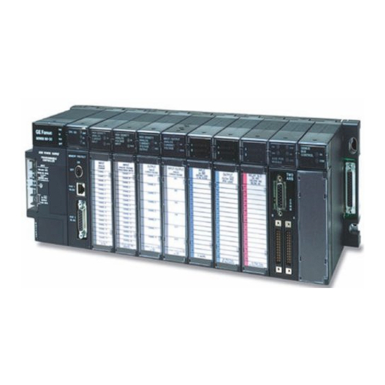
Overview of the Series 90-30 PLC Chapter The Series 90-30 Programmable Logic Controller (PLC) is a member of the GE Series 90 PLC family. The Basic Parts of a Series 90-30 PLC The Series 90-30 PLC is very versatile because (1) it is programmable, and (2) it is assembled from a wide variety of modular, plug-together components. -
Page 33: Assembling A Basic Series 90-30 Plc System
Cables These connect the PLC components together or to other systems. Many standard prefabricated cables are available from GE . They are primarily used to: Interconnect baseplates Connect a programmer to the CPU or to an option module Connect option modules to field devices or other systems. - Page 34 PROGRAMMABLE CONTROLLER BASE 5-SLOT CAUTION USER PROGRAM AND REGISTER VALUES MAY BE LOST IF POW ER SUPPLY IS REMOVED FOR LONGER THAN I/O Bus 1 HOUR. Memory Backup Expansion Power Warning Label Connector CPU/1 Supply CPU Slot (Slot 1) Figure 1-1. Five-Slot CPU Baseplate Next, we’ll add a power supply module.
- Page 35 Then add a CPU module. A CPU module can only mount in baseplate slot 1, next to the power supply. Slot 1 has a unique connector that will only fit CPU or special Option modules. CPU331 Figure 1-3. CPU Module To finish, we will add some I/O modules to baseplate slots 2 through 5.
- Page 36 a44564A PROGRAMMABLE CONTROLLER BASE 5-SLOT CAUTION NON-CPU SLOTS USER PROGRAM AND REGISTER VALUES MAY BE LOST IF POWER SUPPLY IS REMOVED FOR LONGER THAN 1 HOUR I/O-2 I/O-3 I/O-4 I/O-5 CPU/1 POWER SUPPLY Series 90-30 CPU331 BATT HIgh Capacity Power Supply A1 2 3 4 5 6 7 8 B1 2 3 4 5 6 7 8 A1 2 3 4 5 6 7 8...
-
Page 37: What Else Would Be Needed To Make This Basic System Functional
Wiring. This includes properly installed incoming power to the power supply, as well as wiring from the I/O modules to field devices such as switches, sensors, solenoids, relays, etc. Program. An application program for the PLC to run. This is developed with GE PLC programming software. -
Page 38: What If The Application Requires More Than Ten Modules
What if the application requires more than ten modules? You can add one or more Expansion or Remote racks to this system. Some CPUs can support up to seven additional racks. If you added seven additional 10-slot racks, you could have 70 more modules. -
Page 39: What Is The Difference Between Expansion And Remote Baseplates
The next figure shows a system that has a CPU baseplate, one Expansion rack and three Remote racks. Notice that the last rack, the one at the end of the I/O Expansion Bus, must be terminated. A convenient way of terminating the bus is with an IC693ACC307 I/O Bus Terminator Plug, as shown. -
Page 40: What If I Need To Cover More Than 700 Feet (213 Meters)
What if I need to cover more than 700 feet (213 meters)? You can cover much greater distances by using Series 90-30 communications option modules. For example, Genius Bus Controller Modules (GBC) can communicate at distances up to 7,500 feet (2,286 meters) over a shielded twisted-pair cable, as shown in Example 1 below. -
Page 41: Chapter 2 Installation
All software product registration cards should be completed and returned to GE. See “Module Features” in this chapter for location of module serial numbers. See “Common Baseplate Features” in chapter 3 for location of baseplate serial numbers. -
Page 42: Working With Series 90-30 Modules
Working with Series 90-30 Modules Module Features IC693CPUxxx CPU MODULE 25 MHZ LISTED xxxxxxx 123456789 123456789 Figure 2-1. Features of Series 90-30 Module Pivot hook Circuit board holding tabs (two on each side of module) Catalog number and description section of label (Includes MAC address for CPU374.) Certification (UL, CE, etc.) section of label Module connector - plugs into baseplate backplane connector Release lever - spring loaded... -
Page 43: Installing A Module
Installing a Module Warning Do not insert or remove modules with power applied. This could cause the PLC to stop or malfunction. Injury to personnel and damage to the module or baseplate may result. Also, attempts to force a module into an improper slot type will result in damage to the module and/or the baseplate. -
Page 44: Removing A Module
Removing a Module Warning Do not insert or remove modules with power applied. This could cause the PLC to stop or malfunction. Injury to personnel and damage to the module or baseplate may result. Also potentially dangerous voltages from user devices may be present on a module’s screw terminals even though power to the rack is turned off. -
Page 45: Installing A Module's Terminal Board
Installing a Module’s Terminal Board Note: Modules IC693MDL730F (and later) and IC693MDL731F (and later) have special terminal boards that are equipped with holding screws. For Installation and Removal instructions, please see the section “Installing and Removing Terminal Boards with Holding Screws” later in this chapter. -
Page 46: Removing A Module's Terminal Board
Removing a Module’s Terminal Board To remove a terminal board: Open the plastic terminal board cover. Push up on the jacking lever to release the terminal block. JACKING LEVER Grasp pull-tab and pull it towards you until contacts have separated from module housing and bottom pivot hook has disengaged. -
Page 47: I/O Module Terminal Board Posts
I/O Module Terminal Board Posts The terminal board has three posts on the left side. The top and bottom posts hold the terminal board cover in place. The middle post keeps the terminal board wiring in place. If you do not require it to hold the wiring in place, the middle post can be easily snapped off. -
Page 48: Baseplate Mounting
Baseplate Mounting Warning Be sure to follow baseplate grounding instructions in this chapter. Failure to properly ground the PLC can result in improper operation, damage to equipment, and injury to personnel. Mounting a Baseplate to a Panel Use four good-quality 8-32 x 1/2 (4 x 12mm) machine screws, lock washers and flat washers. Install the screws in four tapped holes. - Page 49 IC693ACC313 Recessed Mount Adapter Bracket. Used to recess mount a baseplate inside a 19” rack. A baseplate mounts on the rear panel of this adapter bracket using four 8-32 (4mm) screws, nuts, lock washers, and flat washers. The Adapter Bracket bolts through its four slotted holes to the face of the 19”...
- Page 50 0.160 (4.06) dia. x 4 0.280 (7.1) 3.540 (90) 4.000 (101.6) 1.630 (41.4) 1.368 (34.7) 0.842 (21.4) 0.346 (8.8) Inside 16.850 (428) 18.122 (460.3) 0.439 (11.2) DIMENSIONS IN INCHES (MILLIMETERS IN PARENTHESES) Figure 2-9. IC693ACC313 Recessed Mount Adapter Bracket 2-10 Series 90-30 PLC Installation and Hardware Manual –...
-
Page 51: Grounding Procedures
Grounding Procedures System Grounding Procedures Warning In addition to the following grounding information, we strongly urge that you follow all applicable codes that apply to your area. For example, in the United States, most areas have adopted the National Electrical Code standard and specify that all wiring conform to its requirements. -
Page 52: Series 90-30 Plc Equipment Grounding
Series 90-30 PLC Equipment Grounding Equipment grounding recommendations and procedures are listed below. These grounding procedures must be properly followed for safe, proper operation of your Series 90-30 PLC system. Baseplate Safety Grounding The following recommendations are offered, but applicable safety codes for your area or equipment type should also be consulted. -
Page 53: Grounding 19" Rack-Mounted Baseplates
All baseplates grouped together in a Series 90-30 PLC system must have a common ground connection. This is especially important for baseplates that are not mounted in the same control cabinet. Grounding 19" Rack-Mounted Baseplates There are two Adapter Brackets used for mounting a 10-slot Series 90-30 baseplate to a 19” Rack. Regardless of which of the two Adapter Brackets is used, the 19”... -
Page 54: Module Shield Grounding
Module Shield Grounding In general, the aluminum PLC baseplate is used for module shield grounding. On some Series 90-30 modules, shield connections to the user terminal connector on the module are routed to the baseplate through the module’s backplane connector. Other modules, such as CPUs 351, 352, 363, 364, and 374 require a separate shield ground. - Page 55 The second method, which can be used for systems in noisy environments consists of installing the green ground wire and the optional grounding bracket (part number 44C715646-001R01). This bracket attaches to the CPU using two #4 thread-rolling screws (part number N666P9004B6) and to the grounded enclosure using two #6 thread-rolling screws (part number N666P13006B6).
-
Page 56: Cpu363, Cpu364, And Cpu374 Shield Grounding
CPU363, CPU364, and CPU374 Shield Grounding The CPU363, CPU364, and CPU374 modules must be connected to frame ground at the slot where they are installed. Each module comes with a grounding wire for this purpose. These modules do not support or require the use of a grounding bracket. If the ring terminal on the grounding wire is to be mounted to a painted surface, remove the paint under the ring terminal to ensure good contact, or place a star lock washer between the ring terminal and the painted surface. -
Page 57: General Wiring Guidelines
General Wiring Guidelines Warning In addition to the following wiring suggestions, we strongly urge that you follow all wiring and safety codes that apply to your area or your type of equipment. For example, in the United States, most areas have adopted the National Electrical Code standard and specify that all wiring conform to its requirements. -
Page 58: Discrete I/O Module Connection Methods
Where AC or Output wiring bundles must pass near noise-sensitive signal wiring bundles, avoid running them beside each other. Route them so that, if they have to cross, they do so at a right angle. This will minimize coupling between them. Grouping Modules to Keep Wires Segregated If practical, grouping similar modules together in the PLC racks can help keep wiring segregated. -
Page 59: Terminal Block Quick Connect Installation For 16-Point Discrete Modules
For 24 volt DC input modules, an internal 24 volt power connection is provided on the terminal board to supply a limited number of input devices. Also, a 24 volt DC output is available on the power supply module’s terminal board to supply a limited number of output devices. Terminal Block Quick Connect Installation for 16-Point Discrete Modules The Terminal Block Quick Connect (TBQC) Assembly is an option for certain Series 90-30 discrete I/O modules. -
Page 60: Using A Generic Terminal Block Or Strip
Using a Generic Terminal Block or Strip Mount terminal block/strip to the enclosure panel. Connect an IC693CBL308 or 309 cable, or a custom made cable, to the module’s faceplate connector and wire the stripped ends of the cable to the terminal block/strip. See Chapter 10 for cable data. -
Page 61: Direct Method
Direct Method Connect an IC693CBL327/328 cable, or a custom made cable, to the module’s faceplate connectors, and wire the stripped ends of the cable directly to the field devices. See Chapter 10 for cable data. See the Series 90-30 PLC I/O Module Specifications Manual, GFK-0898, for pin-out information. -
Page 62: Tbqc Not Recommended For Analog Modules
Ground the shield at the field device end, exposing a minimum amount of conductor to the noisy environment. Do not connect the shield at the module end (cut shield off at module end of cable and insulate with shrink tubing). TBQC not Recommended for Analog Modules The Terminal Block Quick Connect (TBQC) Assembly is not recommended for use with analog modules due to cable shielding requirements. -
Page 63: Ac Power Source Connections
AC Power Source Connections AC Input Wiring to AC/DC Power Supplies Warning If the same AC power source is used to provide AC power to other baseplates in a Series 90-30 PLC System, ensure that all AC input connections are identical at each rack. -
Page 64: Power Supply Overvoltage Protection Devices
INPUT INPUT 100-240 VAC 100-240 VAC 50/60HZ 90VA 50/60HZ 90VA 125 VDC, 50W Input Power Input Power 125 VDC, 50W Factory Jumper 24 VDC Output 24 VDC OUTPUT For I/O Modules 0.8A MAX. 24 VDC Output 24 VDC OUTPUT For I/O Modules 0.8A MAX. -
Page 65: Special Installation Instructions For Floating Neutral (It) Systems
Special Installation Instructions for Floating Neutral (IT) Systems When the AC input power supplies listed below are installed in a system where the Neutral line is not referenced to Protective Earth Ground, these special installation instructions must be followed to prevent damage to the power supply. IC693PWR321S (or later version) IC693PWR330A (or later version) Definition of Floating Neutral Systems... -
Page 66: Use These Special Installation Instructions For Floating Neutral Systems
Use These Special Installation Instructions for Floating Neutral Systems The input power terminals should be wired according to the instructions in the “AC Power Source Connections” section of this chapter. The factory installed jumper between terminals 3 and 4 of the Power Supply module must be removed if using one of the Power Supplies that have this feature. -
Page 67: Dc Power Source Connections
DC Power Source Connections DC Input Wiring to AC/DC and DC-Only Power Supplies DC Input power can range from 12 to 30 VDC for the 24 VDC supply, 18 to 56 VDC for the 24/48 VDC supply or 100 to 150 VDC for the 125 VDC supply. All Series 90-30 power supplies have DC input capabilities. -
Page 68: Basic Installation Procedure
Finish laying (marking hole locations) out the rest of the system. This includes any terminal blocks you will be using. DIN-rail mounted terminal blocks for some of the 32-point I/O modules are manufactured by Weidmuller. DIN-rail mounted GE Terminal Block Quick Connect (TBQC) assemblies are optional for some of the 16-point and 32-point discrete I/O modules. - Page 69 10. On the last I/O Bus Expansion Connector, plug in an I/O Bus Expansion Terminator, Catalog Number IC693ACC307 (unless using a cable with built-in terminator resistors, which would either be GE cable IC693CBL302, or your own custom-built cable). 11. Install the modules in their correct slots using your system layout drawings. (The label on the side of each module identifies the module type and catalog number.) Refer to the section...
-
Page 70: Chapter 3 Baseplates
Baseplates Chapter Baseplate Types A baseplate is composed of three main parts: (1) a circuit board mounted to (2) a metal back-plate with (3) a plastic cover. The circuit board, called the “backplane,” contains sockets for plug-in modules. The metal back-plate has four holes for mounting the baseplate, and retainers for mounting the modules. -
Page 71: Two Baseplate Sizes
PROGRAMMABLE CONTROLLER BASE 5-SLOT CAUTION NON-CPU SLOTS USER PROGRAM AND REGISTER VALUES MAY BE LOST IF POWER SUPPLY IS REMOVED FOR LONGER THAN 1 HOUR I/O-2 I/O-3 I/O-4 I/O-5 POWER CPU/1 SUPPLY Module retainers Upper mounting holes Baseplate description Lower mounting holes. The plastic cover is slotted at these two holes to facilitate a ground connection. -
Page 72: Baseplate Terms
Baseplate Terms Backplane: Refers to the circuit board in the baseplate. It contains the baseplate circuitry and sockets for plug-in modules. Rack: This term applies to an assembly consisting of a baseplate, power supply, and other modules. Rack Number: In systems that require more than one rack, each rack is given its own unique number, which enables the CPU to distinguish one rack from another. -
Page 73: Cpu Baseplates
CPU Baseplates There are two basic kinds of CPU baseplates, embedded and modular. The embedded types fulfill the need for a good low cost PLC, but lack the power, expandability, and versatility of the modular systems. Embedded CPU Baseplate: This type has CPU and memory integrated circuit chips soldered to its backplane circuit board. - Page 74 Replaceable System (firmware) PROM Socket for Optional Program PROM SYSTEM PROGRAM PROM PROM PROGRAMMABLE CONTROLLER Description Label BASE 5-SLOT Says "With CPU" WITH CPU CAUTION NON-CPU SLOTS USER PROGRAM AND REGISTER VALUES MAY BE Memory Backup LOST IF POWER SUPPLY IS Warning Label REMOVED FOR LONGER THAN...
-
Page 75: Modular Cpu Baseplates (Figures 3-4 And 3-5)
Modular CPU Baseplates (Figures 3-4 and 3-5) A Power Supply module must be plugged into the left slot (which is not numbered) of these baseplates. The left slot is a unique size and type that only supports a Power Supply module. A CPU module (or a special Option module) must be installed in Slot 1 of these baseplates. -
Page 76: Expansion Baseplates (Figures 3-6 And 3-7)
Expansion Baseplates (Figures 3-6 and 3-7) There can be no more than a total of 50 feet (15 meters) of cable interconnecting Expansion baseplates and the CPU baseplate. An Expansion baseplate cannot stand alone. It must be connected to a system that has a CPU. The CPU can be in a PLC or in a Personal Computer that is equipped with a Personal Computer Interface Card (see Chapter 11). -
Page 77: Remote Baseplates (Figures 3-8 And 3-9)
EXPANSION RACK # 1 2 3 4 5 6 7 PROGRAMMABLE CONTROLLER X = CLOSED BASE 10-SLOT EXPANSION NON-CPU SLOTS NON-CPU SLOTS POWER I/O-1 I/O-2 I/O-3 I/O-4 I/O-5 I/O-6 I/O-7 I/O-8 I/O-9 I/O-10 SUPPLY Figure 3-7. IC693CHS392 10-Slot Expansion Baseplate Remote Baseplates (Figures 3-8 and 3-9) There can be no more than 700 feet of cable connecting all baseplates in a system that uses Remote baseplates. - Page 78 EXPANSION RACK # PROGRAMMABLE X X X CONTROLLER X = CLOSED BASE 5-SLOT REMOTE NON-CPU SLOTS POWER I/O-1 I/O-2 I/O-3 I/O-4 I/O-5 SUPPLY Figure 3-8. IC693CHS399 5-Slot Remote Baseplate EXPANSION RACK # 1 2 3 4 5 6 7 PROGRAMMABLE CONTROLLER X = CLOSED BASE 10-SLOT...
-
Page 79: I/O Bus Expansion Cables
I/O Bus Expansion Cables Five prewired I/O Bus Expansion cables are available from GE. Catalog numbers and lengths of these cables are listed in the following figure. You can build custom cables to suit the needs of your application if cable lengths other than those listed are required. Refer to the “Cables”... -
Page 80: Differences Between Remote And Expansion Racks
Differences Between Remote and Expansion Racks Basically, Remote racks provide the same functionality as Expansion racks, but with the longer distance (700 feet/213 meters verses 50 feet/15 meters for Expansion racks) capability. To minimize unbalanced ground conditions, Remote baseplates have extra isolation circuitry. Unbalanced ground conditions can occur when systems are located long distances from each other and do not share the same ground system. -
Page 81: Termination Requirement For Expansion Or Remote System
Termination Requirement for Expansion or Remote System When two or more baseplates are connected via the I/O Bus Expansion System, the I/O Expansion Bus must be properly terminated. The most common method of terminating the I/O Expansion Bus is by installing a termination resistor pack (IC693ACC307) on the open connector on the last (most distant from the CPU) Expansion or Remote baseplate in the system. -
Page 82: Rack Number Dip Switch On Expansion And Remote Baseplates
Rack Number DIP Switch on Expansion and Remote Baseplates Each baseplate in a Series 90-30 system is identified with a unique number called a “Rack Number.” Rack Numbers for Expansion and Remote baseplates are selected by setting a DIP switch located on each baseplate directly above the connector for Slot 1. Rack number 0 must always be present and is assigned, by default, to the CPU rack (the CPU baseplate does not have this DIP switch). - Page 83 Expansion Rack Connection Example The following example shows a system that includes Expansion baseplates. PROGRAMMER CPU BASEPLATE SERIAL NOTE TOTAL MAXIMUM DISTANCE FROM CPU BASEPLATE DISCRETE/ANALOG/OPTION TO LAST EXPANSION BASEPLATE IS EXPANSION BASEPLATE 50 FEET (15 METERS) I/O EXPANSION CABLES DISCRETE/ANALOG/OPTION EXPANSION BASEPLATE DISCRETE/ANALOG/OPTION...
-
Page 84: Expansion And Remote Baseplates Connection Example
Expansion and Remote Baseplates Connection Example The following example shows cable connections in a system that includes both remote and expansion baseplates. A system can have a combination of remote and expansion baseplates as long as the distance and cable requirements are followed. CPU BASEPLATE BASEPLATE IC693CHS391/397... - Page 85 Baseplate Mounting Dimensions Note: Series 90-30 PLCs must be mounted in a protective enclosure. The enclosure should be capable of properly dissipating the heat produced by all of the devices mounted inside it. For details on calculating heat dissipation, refer to Appendix F. Series 90-30 PLC baseplates are designed to be panel mounted.
- Page 86 DIMENSIONS IN INCHES, 4.00 17.44 4.00 MILLIMETERS ARE IN PARENTHESIS (102) (443) (102) 4.00 16.85 (102) (428) REMOVABLE 15.60 5.59 (396) (142) TERMINAL BLOCK POWER SUPPLY .20 DIA. 3.54 (5.08) 5.12 (90) (TYPICAL) (130) FRONT VIEW SIDE VIEW HINGED (20) DOOR 4.00 (102)
- Page 87 Modular CPU, Expansion, and Remote Baseplate Dimensions Baseplate dimensions and spacing requirements for installation for Modular CPU baseplates are shown below. DIMENSIONS IN INCHES, 10.43 4.00 4.00 MILLIMETERS ARE IN PARENTHESIS (265) (102) (102) 4.00 9.84 (102) (250) REMOVABLE 8.60 5.59 (218) (142)
-
Page 88: Load Ratings, Temperature, And Mounting Position
Load Ratings, Temperature, and Mounting Position The power supply load rating depends on the mounting position of the baseplate and the ambient temperature. The load rating with the baseplate mounted upright on a panel is: 100% at 60°C (140°F) Power supply load ratings with the baseplate mounted horizontally are: temperature at 25°C (77°F) –... -
Page 89: Baseplate Adapter Brackets For 19" Rack Mounting
Baseplate Adapter Brackets for 19" Rack Mounting Two optional Baseplate Adapter Brackets allow a 10-slot baseplate to be mounted in a 19 inch rack. Each baseplate installation requires only one of the adapter brackets. Warning Be sure to follow grounding instructions in Chapter 2 when using these adapter brackets. - Page 90 Dimensions for rack mounting a 10-slot baseplate with the IC693ACC308 Front Mount Adapter Bracket are shown in the following figure. 18.89 (480) 18.47 (469) DIMENSIONS IN INCHES (MILLIMETERS IN Figure 3-19. Dimensions for 19” Rack Mounting Using IC693ACC308 Adapter Bracket 0.160 (4.06) dia.
-
Page 91: Baseplate Comparison Table
Baseplate Comparison Table Table 3-2. Series 90-30 Baseplate Comparison Series 90-30 Baseplates Catalog Number Type Size (Slots) IC693CPU311 Embedded CPU IC693CPU313 Embedded CPU IC693CPU323 Embedded CPU IC693CHS397 Modular CPU IC693CHS391 Modular CPU IC693CHS398 Expansion IC693CHS392 Expansion IC693CHS399 Remote IC693CHS393 Remote 3-22 Series 90-30 PLC Installation and Hardware Manual –... -
Page 92: Chapter 4 Power Supplies
Power Supplies Chapter Power Supply Categories Series 90-30 power supplies are modular types that plug into the left slot of all 90-30 baseplates. They have been placed into two categories for the purpose of this chapter: AC/DC Input Power Supplies IC693PWR32 , Standard 20/240 VAC or 25 VDC input, 30 watts total output IC693PWR330, High Capacity 20/240 VAC or 25 VDC input, 30 watts total output DC Input-Only Power Supplies... -
Page 93: Ac/Dc Input Power Supplies
AC/DC Input Power Supplies IC693PWR321 Standard Power Supply, 120/240 VAC or 125 VDC Input The IC693PWR32 is a 30 watt supply that can operate from an input voltage source in the range of 85 to 264 VAC or 00 to 300 VDC. This power supply provides three outputs: +5 VDC output, +24 VDC Relay power output which provides power to circuits on Series 90-30 Output Relay modules. - Page 94 Table 4-3. Specifications for IC693PWR321 Standard AC/DC Input Power Supply 20/240 VAC or 25 VDC Nominal Rated Voltage Input Voltage Range 85 to 264 VAC 00 to 300 VDC 90 VA with VAC Input Input Power 50 W with VDC Input (Maximum with Full Load) 4A peak, 250 milliseconds maximum Inrush Current...
-
Page 95: Ic693Pwr330 High Capacity Power Supply, 120/240 Vac/125 Vdc Input
IC693PWR330 High Capacity Power Supply, 120/240 VAC/125 VDC Input The IC693PWR330 High Capacity Power Supply is rated for 30 watts output. For applications requiring greater +5V current capacity than is available with the standard supply (IC693PWR321), this supply allows all 30 watts to be consumed from the +5V supply. It can operate from an input voltage source in the range of 85 to 264 VAC or 00 to 300 VDC. -
Page 96: Field Wiring Connections For The Ac/Dc Input Power Supplies
Table 4-5. Specifications for IC693PWR330 High Capacity AC/DC Input Power Supply Nominal Rated Voltage 20/240 VAC or 25 VDC Input Voltage Range 85 to 264 VAC 00 to 300 VDC 00 VA with VAC Input Input Power 50 W with VDC Input (Maximum with Full Load) 4A peak, 250 ms maximum Inrush Current... -
Page 97: Isolated 24 Vdc Supply Output Connections
If you want to Hi-pot test this supply, overvoltage protection must be disabled during the test by removing the terminal strip jumper strap. Re-enable overvoltage protection after testing by reinstalling the strap. Frame Ground Jumper Strap Connects Overvoltage Protection Devices to Frame Ground Screw Terminals on Terminal Board Figure 4-3. -
Page 98: Dc Input Only Power Supplies
DC Input Only Power Supplies IC693PWR322 Standard Power Supply, 24/48 VDC Input The IC693PWR322 is a 30 watt output power supply designed for 24 VDC or 48 VDC nominal inputs. It will accept an input voltage range from 8 VDC to 56 VDC. Although it is capable of maintaining all outputs within specifications with input voltages as low as 8 VDC, it will not start with initial input voltages of less than 2 VDC. -
Page 99: Calculating Input Power Requirements For Ic693Pwr322
Table 4-7. Specifications for IC693PWR322 Power Supply 24 or 48 VDC Nominal Rated Voltage Input Voltage Range 2 to 56 VDC Start 8 to 56 VDC 50 watts maximum at full load Input Power Inrush Current 4A peak, 00 ms maximum 5 VDC: 5 watts maximum Output Power 24 VDC Relay: 5 watts maximum... - Page 100 Input Power/Current Calculation Determine total output load from typical specifications listed for individual modules in Chapters 2 and 3. Use the graph to determine average input power. Divide the input power by the operating source voltage to determine the input current requirements.
-
Page 101: Ic693Pwr328 Standard Power Supply, 48 Vdc Input
IC693PWR328 Standard Power Supply, 48 VDC Input The IC693PWR328 is a 30 watt output power supply designed for 48 VDC nominal input. It will accept an input voltage range from 38 VDC to 56 VDC. This power supply provides the following outputs: +5 VDC output. -
Page 102: Calculating Input Power Requirements For Ic693Pwr328
Table 4-9. Specifications for IC693PWR328 Power Supply 48 VDC Nominal Rated Voltage 38 to 56 VDC Input Voltage Range 50 watts maximum at full load Input Power Inrush Current 4A peak, 00 ms maximum Output Power 5 VDC: 5 watts maximum 24 VDC Relay: 5 watts maximum 24 VDC Isolated: 20 watts maximum NOTE: 30 watts maximum total (all three outputs) -
Page 103: Input Power/Current Calculation For Ic693Pwr328 Power Supply
Input Power/Current Calculation for IC693PWR328 Power Supply Determine total output load from typical specifications listed for individual modules in Chapter 2. Use the graph to determine average input power. Divide the input power by the operating source voltage to determine the input current requirements. -
Page 104: Ic693Pwr331 High Capacity Power Supply, 24 Vdc Input
IC693PWR331 High Capacity Power Supply, 24 VDC Input The Series 90-30 DC input High Capacity power supply (IC693PWR33 ) is a 30 watt wide range supply designed for 24 VDC nominal inputs. For applications requiring greater +5V current capacity than is available with the standard supply, this supply allows all 30 watts to be consumed from the +5 V output. -
Page 105: Current Derating For Higher Temperatures
Table 4-11. Specifications for IC693PWR331 Power Supply 24 VDC Nominal Rated Voltage Input Voltage Range 8 to 30 VDC Start 2 to 30 VDC 50 watts maximum at full load Input Power Inrush Current 5 VDC: 30 watts maximum ** Output Power 24 VDC Relay: 5 watts maximum 24 VDC Isolated: 20 watts maximum... -
Page 106: Calculating Input Power Requirements For Ic693Pwr331
Calculating Input Power Requirements for IC693PWR331 Use the following procedure to determine input power requirements for the 24 VDC High Capacity Power Supply: Determine total output power load from typical specifications listed for individual modules at the end of this chapter. Multiply the output power by .5 to determine the input power value. -
Page 107: Common Series 90-30 Power Supply Features
Common Series 90-30 Power Supply Features Status Indicator Lights on all Power Supplies Four LEDs are located on the upper right front of the power supply faceplate. The purpose of these LEDs is as follows: The top green LED, labeled PWR, provides an indication of the operating state of the power supply. -
Page 108: Output Voltage Connections To Backplane (All Supplies)
Frame Ground Jumper Strap Connects Overvoltage Protection Devices to Frame Ground Screw Terminals on Terminal Board Figure 4-10. Overvoltage Protection Devices and Jumper Strap Output Voltage Connections to Backplane (All Supplies) The following figure illustrates how these three output voltages are connected internally to the backplane on the baseplate. -
Page 109: Overcurrent Protection (All Supplies)
Overcurrent Protection (all Supplies) The 5V logic output is electronically limited to 3.5 amps (7 amps for high capacity supplies). An overload (including short circuits) is sensed internally and causes the supply to shut down. The supply will continually try to restart until the overload is removed. An internal fuse in the input line is provided as a backup. -
Page 110: Cpu Serial Port Connector On Power Supply (All Supplies)
A 5-pin D-type female connector, accessed by opening the hinged door on the right front of the power supply, provides the connection to a CPU serial port which is used to connect to: A programmer (usually a personal computer) running GE PLC programming software. The GE Hand-Held Programmer. -
Page 111: Backup Battery For Ram Memory (All Supplies)
Backup Battery for RAM Memory (All Supplies) The long-life Lithium battery (IC693ACC30 ) used to maintain the contents of the CMOS RAM memory in the CPU is accessed by removing the cover plate located at the bottom of the power supply faceplate. -
Page 112: Chapter 5 Cpus
CPUs Chapter CPU Types for Series 90-30 PLCs There are numerous CPU models available for the Series 90-30 PLC which differ in speed, I/O capacity, size of user memory, and advanced features. This variety of models gives a system designer considerable flexibility in choosing the one best suited to the system being designed. There are two basic types of CPUs, Embedded and Modular. -
Page 113: Modular Cpus
a44563A Socket for Optional Program PROM Replaceable System (firmware) PROM SYSTEM PROGRA PROM PROM PROGRAMMABL CONTROLLER Description Label BASE 5- Says "With CPU" WITH CPU CAUTION NON-CPU SLOTS USER AND REGISTER VALUES MAY BE Memory Backup LOST IF POWER SUPPLY IS Warning Label REMOVED FOR LONGER THAN... -
Page 114: General Cpu Features
CPU serial port which is used to connect to: a programmer (usually a personal computer) running GE PLC programming software. The IC690ACC901 Miniconverter/cable kit is a convenient way to access this port. See Appendix D for details. -
Page 115: Memory Volatility
SERIAL PORT Figure 5-3. CPU Serial Port Connector on Power Supply This serial port is RS-485 compatible, and uses the GE SNP (Series Ninety Protocol) protocol (slave only). Breakfree SNP became the default protocol on all serial ports on the Series 90-30 CPUs, starting with firmware release 9.00 for CPUs 350–364, and firmware... -
Page 116: Ram Memory
RAM Memory Every Series 90-30 CPU uses RAM memory for its ”working memory.” The RAM chips used are of the CMOS type. CMOS RAM is an acronym for Complimentary Metal-Oxide Semiconductor, Random Access Memory. CMOS RAM is a relatively fast, low power memory that can be easily examined (read) and changed (written to). - Page 117 GE Web site lists CPU revision histories, matching version numbers to associated features. See Chapter 13 for information on the GE Web site. Users who could benefit from a new firmware release may choose to upgrade their CPU by installing new firmware. Upgrades come in two formats, depending on the type of CPU to be upgraded.
- Page 118 CPU module (if it has one). The applicable method will be documented in your upgrade kit instructions. Downloadable firmware upgrade files are also found in the Technical Support area of the GE Web site. See Chapter 13 for Web site information.
- Page 119 These letters can be cross-referenced to the firmware version. A revision history list for Series 90-30 products, including CPUs, can be found in the GE web site technical support area (www.ge-ip.com/support) that cross-references revision letters, firmware versions, and related features. Also, if you have access to the progression of IPIs that were issued for the particular CPU (these are available on the GE PLC InfoLink CD-ROM) you can find the desired cross-reference.
- Page 120 Always keep a backup copy of your current program files in case of an emergency. EEPROM and EPROM devices, listed in the following table, are available from GE. Table 5-2. EPROM and EEPROM Catalog Numbers Third Party Source...
- Page 121 Series 90-30 CPU Capacities The following table describes the maximum capacities and operating features for the Series 90-30 PLC CPU models. For State Logic CPUs, see “System Specifications for Series 90-30 State Logic CPUs” in Chapter 9. Table 5-3. Series 90-30 CPU Capacities Speed, Input Output...
- Page 122 User Memory Reference Types The user references referred to in the following tables are explained in the Series 90-30 PLC CPU Instruction Set Reference Manual, GFK-0467. Table 5-4. Range and Size of User References for CPU Models 311-341 Reference (Memory) Type Model 311/313/323 Model 331/340/341 Reference Range...
- Page 123 Table 5-5. Range and Size of User References for CPU Models 350 through 374 Reference Type Model 350/351/352/360/363/364/374 CPU Reference Range Size Maximum User memory* Not applicable 240K Bytes, configurable (CPU350: 32K Bytes, fixed) Discrete inputs %I0001 – %I2048 2048 bits Discrete outputs %Q0001 –...
- Page 124 Compatibility With Hand-Held Programmer (HHP) and Memory Card The user program in CPUs 350—374 cannot be viewed or edited with the Series 90-30 Hand- Held Programmer (IC693PRG300). You must use one of the GE programming software packages to create or edit CPU 350—-374 user programs.
- Page 125 350–374 CPU Advanced Features Advanced features of 350 – 374 CPUs Feature CPU350 CPU351 CPU352 CPU360 CPU363 CPU364 CPU374 Memory 240K 240K 240K 240K 240K 240K fixed Configurable Configurable Configurable Configurable Configurable Configurable Serial Ports Floating- Point Math (Firmware) (Firmware) (Hardware) (Firmware) (Firmware)
- Page 126 Additional Serial Ports (CPU351, CPU352, CPU363) Although all Series 90-30 CPUs have a serial port that is accessed through the connector on the power supply, the CPU351, CPU352, and CPU363 each have two additional serial ports. The connectors for these additional serial ports are mounted on the front of each CPU. These two built- in serial ports eliminate the need for the CPU to access serial ports across the PLC backplane, resulting in better system performance.
- Page 127 Run/Stop (configurable): This feature was introduced in CPU firmware release 7.0. It is, by default, disabled. It is not functional unless the R/S Switch: parameter on the CPU configuration screen is set to Enabled. This feature, when enabled, lets you stop the PLC by turning the key switch to OFF, or start the PLC running by turning the key switch to ON (if there are no faults).
- Page 128 10BASE-T port. However, if you choose, you may use an external transceiver by connecting to the CPU364’s AAUI port, which bypasses the internal transceiver (see Appendix J for GE transceiver information). The CPU374 does not require an external transceiver for either of its 10/100 BASE T/TX ports.
- Page 129 Hardware Features of the 350–364 CPUs CPU350 and CPU360 Hardware Features These two modules look identical except for labeling. These modules feature an LED light, labeled “PS Port” that indicates serial port activity through the serial connector on the PLC power supply. Typically, this LED will flash while data is being transferred through the port, and will stay off when the port is inactive.
- Page 130 CPU351, CPU352, and CPU363 Hardware Features These three modules are similar in features and functionality. The CPU351 and CPU352 look identical except for labeling. The CPU363 has the same features as the other two, but the orientation of its Port 1 and Port 2 connectors is reversed from those of the CPU351 and CPU352, and its LED indicator lights, key switch, and shield ground connector are in different locations.
- Page 131 Shield Ground Connection Tab This tab is located on the bottom of the CPU351 and 352 modules and on the front of the CPU363 module. It is used to make the module’s shield ground connection. A wire with the applicable terminal ends is supplied with the module for this purpose.
- Page 132 Protocols Supported Starting with Firmware Release 9.00, breakfree SNP became the default protocol on the three Serial Ports on these modules. See “Breakfree SNP Protocol” on page 5-13 for details. SNP Port (Through Power Supply Connector) SNP slave SNP-X slave Port 1 and Port 2 (Through Module’s Front Panel Connectors) SNP master and slave SNP-X master and slave...
- Page 133 Pin Assignments for CPU351, CPU352, and CPU363 Serial Ports 1 & 2 The following two tables describe the pin assignments for each of the two front panel serial ports on the CPU351, CPU352, and CPU363. Table 5-6. Port 1 (RS-232) Signal Number Name...
- Page 134 CPU364 Hardware Features This module has four LED indicator lights, an Ethernet Restart pushbutton, a standard CPU keyswitch, three port connectors, and a shield ground connection tab (labeled “FRAME”). PORT CPU 364 STAT ETHERNET RESTART PORT 1 RS-232 PIN 1 AAUI 10BASE T FRAME...
- Page 135 AAUI port - This 14-pin AAUI port connects via a user-supplied IEEE 802.3 transceiver cable to an external Ethernet-compatible transceiver such as the GE catalog number IC649AEA102 (for 10Base T) or IC649AEA103 (for 10Base 2). See Appendix J for details on these transceivers.
- Page 136 CPU374 Hardware Features This module has eight LED indicators, an Ethernet Restart pushbutton, a standard CPU keyswitch, three port connectors, and a shield ground connection tab (labeled “FRAME”). PORT CPU 374 STAT ETHERNET RESTART STATION PIN 1 LINK/ACT PORT 1 100Mbps LINK/ACT PORT 2...
- Page 137 Keyswitch This is a standard CPU keyswitch, discussed on page 3-15. Front Panel Connectors The full functionality of these ports is detailed in GFK-1541, TCP/IP Ethernet Communications for the Series 90 PLC User’s Manual. Station Mgr - This connector is used to connect a terminal or terminal emulator to access the Station Manager software on the Ethernet Interface.
- Page 138 CPU Data Sheets This section provides data sheets describing each of the Series 90-30 CPU modules. For information on the State Logic CPUs, see Chapter 9, “State Logic Products.” CPU Model List IC693CPU311 5-slot baseplate with embedded CPU, 1K Byte Register Memory IC693CPU313 5-slot baseplate with embedded CPU, 2K Bytes Register Memory IC693CPU323...
- Page 139 Catalog Number IC693CPU311 CPU311 PROGRAMMABLE CONTROLLER BASE 5-SLOT WITH CPU SYSTEM PROGRAM CAUTION PROM PROM USER PROGRAM AND REGISTER VALUES MAY BE LOST IF POWER SUPPLY IS REMOVED FOR LONGER THAN i HOUR POWER SUPPLY CPU Type 5-slot baseplate with embedded CPU Total Baseplates per System Load Required from Power Supply 410 milliamps from +5 VDC supply...
- Page 140 Catalog Number IC693CPU313 CPU313 PROGRAMMABLE CONTROLLER BASE 5-SLOT WITH CPU PROGRAM CAUTION SYSTEM PROM PROM USER PROGRAM AND REGISTER VALUES MAY BE LOST IF POWER SUPPLY IS REMOVED FOR LONGER THAN i HOUR POWER SUPPLY CPU Type 5-slot baseplate with embedded CPU Total Baseplates per System Load Required from Power Supply 430 milliamps from +5 VDC supply...
- Page 141 Catalog Number IC693CPU323 CPU323 CPU Type 10-slot baseplate with embedded CPU Total Baseplates per System Load Required from Power Supply 430 milliamps from +5 VDC supply Processor Speed 10 MegaHertz Processor Type 80188 Operating Temperature 0 to 60 degrees C (32 to 140 degrees F) ambient Typical Scan Rate 0.6 milliseconds per 1K of logic (boolean contacts) User Program Memory (maximum)
- Page 142 CPU331 Catalog Number IC693CPU331 CPU Type Single slot CPU module Total Baseplates per System 5 (1 CPU baseplate + 4 expansion and/or remote) Load Required from Power Supply 350 milliamps from +5 VDC supply Processor Speed 10 MegaHertz Processor Type 80188 Operating Temperature 0 to 60 degrees C (32 to 140 degrees F) ambient...
-
Page 143: Catalog Number Ic693Cpu340
CPU340 Catalog Number IC693CPU340 CPU Type Single slot CPU module Total Baseplates per System 5 (1 CPU baseplate + 4 expansion and/or remote) Load Required from Power Supply 490 milliamps from +5 VDC supply CPU340 Processor Speed 20 MegaHertz Processor Type 80C188XL Operating Temperature 0 to 60 degrees C (32 to 140 degrees F) ambient... -
Page 144: Catalog Number Ic693Cpu341
Catalog Number IC693CPU341 CPU341 CPU Type Single slot CPU module Total Baseplates per System 5 (1 CPU baseplate + 4 expansion and/or remote) Load Required from Power Supply 490 milliamps from +5 VDC supply CPU341 Processor Speed 20 MegaHertz Processor Type 80C188XL Operating Temperature 0 to 60 degrees C (32 to 140 degrees F) ambient... -
Page 145: Catalog Number Ic693Cpu350
Catalog Number IC693CPU350 CPU350 CPU Type Single slot CPU module Total Baseplates per System 8 (CPU baseplate + 7 expansion and/or remote) Load Required from Power Supply 670 milliamps from +5 VDC supply PORT Processor Speed 25 MegaHertz CPU 350 Processor Type 80386EX Operating Temperature... -
Page 146: Cpu351
CPU351 Catalog Number IC693CPU351 CPU Type Single slot CPU module Total Baseplates per System 8 (CPU baseplate + 7 expansion and/or remote) Load Required from Power Supply 890 milliamps from +5 VDC supply CPU 351 Processor Speed 25 MegaHertz Processor Type 80386EX Operating Temperature 0 to 60 degrees C (32 to 140 degrees F) ambient... -
Page 147: Cpu352
Catalog Number IC693CPU352 CPU352 CPU Type Single slot CPU module Total Baseplates per System 8 (CPU baseplate + 7 expansion and/or remote) Load Required from Power Supply 890 milliamps from +5 VDC supply CPU 352 Processor Speed 25 MegaHertz Processor Type 80386EX Operating Temperature 0 to 60 degrees C (32 to 140 degrees F) ambient... -
Page 148: Cpu360
Catalog Number IC693CPU360 CPU360 CPU Type Single slot CPU module Total Baseplates per System 8 (CPU baseplate + 7 expansion and/or remote) Load Required from Power Supply 670 milliamps from +5 VDC supply PORT Processor Speed 25 MegaHertz CPU 360 Processor Type 80386EX Operating Temperature... -
Page 149: Cpu363
Catalog Number IC693CPU363 CPU363 CPU Type Single slot CPU module Total Baseplates per System (CPU baseplate + 7 expansion and/or remote) Load Required from Power Supply 890 milliamps from +5 VDC supply PORT Processor Speed 25 MegaHertz CPU 363 Processor Type 80386EX Operating Temperature 0 to 60 degrees C (32 to 140 degrees F) ambient... -
Page 150: Cpu364
Catalog Number IC693CPU364 CPU364 CPU Type Single slot CPU module with embedded Ethernet Interface Total Baseplates per System 8 (CPU baseplate + 7 expansion and/or remote) Load Required from Power Supply 1.51 Amps from +5 VDC supply Processor Speed 25 MegaHertz CPU 364 Processor Type 80386EX... -
Page 151: Cpu374
CPU374 Catalog Number IC693CPU374 CPU type Single slot CPU module with embedded Ethernet Interface Processor speed 133 MHz PORT Processor Type Embedded 586 CPU 374 Typical Scan Rate 0.15 milliseconds per 1K of logic (boolean contacts) STAT Type of Memory Storage RAM and Flash User Memory (total) 240KB (245,760) Bytes. -
Page 152: Chapter 6 Memory Backup/Battery Backup
Memory Backup/Battery Backup Chapter Backup Battery for RAM Memory (All Supplies) The long-life Lithium battery (IC693ACC301) used to maintain the contents of the CMOS RAM memory in the CPU is accessed by removing the cover plate located at the bottom of the power supply faceplate. -
Page 153: Battery Replacement Instructions
Battery Replacement Instructions Warning To avoid the chance of losing the contents of RAM memory, you can carefully perform the following steps with PLC power ON. This procedure should only be performed by qualified electrical personnel who are trained in applicable electrical safety rules and procedures. Failure to follow standard electrical safety practice can result in injury or death to personnel, damage to equipment, or both. -
Page 154: Battery Replacement/Memory Protection Factors
Train more than one person to load the backup program in case that one person is not available when needed. Information on creating a backup can be found in GE’s software user’s manuals. This procedure is also covered in applicable GE programming software training courses. -
Page 155: Factors Affecting Battery Life
Factors Affecting Battery Life Replacing your battery once per year is a good rule of thumb. However, no one can predict precisely how long a backup battery will last because this depends upon what CPU is used, what temperature it is subjected to, and how it used. Considering the following list of factors that affect battery life will help you decide how frequently to replace the battery in your application: A battery that is not in use has an estimated life (called its ”shelf life”) of 5 years at ”room temperature”... - Page 156 (which, in that case, would probably be a %M coil) to a Human to Machine Interface (HMI) terminal such as a GE CIMPLICITY HMI unit. The HMI could be programmed to display a warning message when that particular bit goes to a logic 1. For more information about System Reference bits and ladder logic programming, see the Series 90-30/20/Micro PLC CPU Instruction Set Reference Manual, GFK-0467.
-
Page 157: Operating Without A Memory Backup Battery
Operating Without a Memory Backup Battery Whether it would be to your advantage to use a battery-less scheme depends on your application. There are various advantages and disadvantages to consider in making your decision. Possible Advantage The obvious advantage of operating without a memory backup battery is that you are freed from the need to maintain the battery. - Page 158 Configuring a Battery-Less System Here are the basic steps to configure a system to run battery-less. When configured this way, the contents of PROM memory will be written into RAM memory each time the PLC powers up. Equip your CPU with a PROM device. On some CPUs a PROM device is purchased as an option;...
-
Page 159: Ram Memory Battery Backup Connection Path
RAM Memory Battery Backup Connection Path CMOS RAM and DRAM memory is a volatile type of memory, which means that it can lose its contents (ladder program, configuration, etc.) if power is removed. To retain RAM memory contents under no-power conditions, a long-life lithium battery is provided. This battery is normally mounted in the rack’s Power Supply module. -
Page 160: Maintaining Ram Memory During Storage Or Shipment Of A Cpu
Maintaining RAM Memory During Storage or Shipment of a CPU Modular CPUs Modular CPUs have an internal connector for a backup battery so that RAM memory contents can be retained while the CPU is being stored or shipped. This arrangement should not to be used when the CPU module is installed in the baseplate and the backup battery is installed in the power supply. -
Page 161: Battery Accessory Kit Installation
POWER SUPPLY CONNECTOR BATTERY PLUG Figure 6-2. Installing the Battery Accessory Kit Battery Accessory Kit Installation 1. Insert the plug on the end of the battery cable into the 2-pin connector on the Battery Accessory board. The battery plug is normally not plugged into the accessory connector. This prevents accidental discharge of the battery during storage and handling. -
Page 162: Batteries In Power Supplies On Expansion Or Remote Racks
Batteries in Power Supplies on Expansion or Remote Racks Batteries in power supplies on Expansion or Remote racks, are not in use. Only the battery in a CPU rack supplies backup power to RAM memory. Batteries in non-CPU racks may be removed and used as spares, if they meet the age requirements stated previously in this chapter. -
Page 163: Chapter 7 Input/Output Modules
Input/Output Modules Chapter The basics of the Series 90-30 Input and Output (I/O) modules are covered in this chapter for your convenience. A table listing these modules is located at the end of this chapter. For detailed specifications and installation instructions, please refer to publication GFK-0898, Series 90-30 PLC I/O Module Specifications. -
Page 164: Discrete I/O Modules
Series 90-30 PLC are available to meet a wide variety of needs. For information on third-party modules, consult the following: Your GE PLC distributor or sales engineer The GE web site at http://www.ge-ip.com... - Page 165 number is also printed on the label on the side of the module. However, in order to see this side label, the module has to be removed from the PLC On the front side of the front cover insert are lines that correspond to the module’s I/O points. You can temporarily remove the insert and write the signal name for each point on the appropriate line, as shown in the example in the figure.
-
Page 166: Wiring Standard Density (16-Point Or Less) Discrete Modules
Wiring Standard Density (16-Point or Less) Discrete Modules There are three basic wiring methods: Direct Method. Run the wires from the field devices (switches, relays, etc.) directly to the screws on the modules’ terminal boards. Terminal Strip Method. Mount a terminal strip inside the control enclosure and wire from the terminal strip to the modules’... - Page 167 A1 2 3 4 5 6 7 8 B1 2 3 4 5 6 7 8 LED Indicators C1 2 3 4 5 6 7 8 D1 2 3 4 5 6 7 8 INPUT 5/12 VDC POS/NEG LOGIC 3.0 mA/Pt at 5VDC Pin B12 Pin A12 Pin A1...
-
Page 168: Wiring Methods For 32-Point Discrete I/O Modules
6 feet (2 meters) long. Chapter 0, “Cables,” has details on these cables. Connect to a user-supplied terminal block/strip or I/O field devices using one of the two GE “interface” cables. These cables have a 50-pin connector on one end that plugs into the module, and stripped, tinned leads on the other for wiring to a terminal block/strip or I/O field devices. -
Page 169: Modules With Dual 24-Pin Connectors
Connect to a pair of Terminal Block Quick Connect (TBQC) terminal blocks (IC693ACC337) using a pair of GE cables. Three lengths of cables are available: 20” (0.5 meter), 3 feet ( meter), 6 feet (2 meters). The cables come in right hand and left hand types because the connectors on the modules are oriented differently (see figure 7-2). -
Page 170: Analog Module Features
Analog Module Features Analog Modules have the following basic features (refer to the following figure): Removable Terminal Board. You can remove the terminal board from the module in order to wire it, if desired. Then, when you are finished wiring it, you can easily reinstall it on the module. -
Page 171: Wiring Methods For Analog Modules
Lens Cap Module OK LED OUTPUT Module Type ANALOG CURRENT VOUT1 Hinged Cover VOUT2 IOUT1 Removeable IOUT2 Insert RTN1 RTN2 Removeable Terminal Board JMPV1 Connection JMPV2 Diagram DEF0 0-20mA 0-20mA Module Catalog 44A729182-021R01 FOR USE WITH IC693ALG391 Figure 7-5. Example of Series 90-30 Analog Current Output Module Wiring Methods for Analog Modules Twisted, shielded instrumentation cable is strongly recommended for analog module input or output signal connections. -
Page 172: Analog Output Module Wiring
Direct Method. Run a shielded cable from the field device (transducer, potentiometer, etc.) directly to the module. Connect the conductors to the applicable screws on the module’s terminal board. Ground the shield at the field device end, exposing a minimum amount of conductor to the noisy environment. - Page 173 I/O Module Wire Routing To reduce noise coupling among PLC wires, it is recommended you keep electrically noisy wiring, such as AC power wiring and Discrete Output Module wiring, physically separated from low-level signal wiring such as connections to DC and Analog Input modules. This can be accomplished by grouping separately, where practical, the following categories of wiring: AC power wiring.
- Page 174 VDC. Although it mounts in a standard Series 90-30 PLC slot, it does not connect to the PLC backplane. Its control power and output power come from an external supply. (The GE IC690PWR 24 stand-alone power supply would be a suitable choice.) This module is designed for TTL (5 VDC) inputs.
- Page 175 DVM Specifications Table 7-1. IC693DVM300 Specifications OUTPUT CHARACTERISTICS Outputs (Channels) per Module Isolation 2500 Vrms (optical isolation) 24 VDC Nominal Output Voltage 26 VDC nominal, 2 VDC minimum, 35 VDC Power Supply for Output Channels maximum .6 Amps maximum per channel Output Current 6.4 Amps maximum total per module 0.32 VDC...
- Page 176 DVM Connections Table 7-2. IC693DVM300 Connections Signal Name Connection Description +28V.IN Module Control Power + input terminal (common on pin 2). Supplies power to module’s signal-level circuits and auxiliary + 5 and - 5 Volt power supplies (pins 2, 3, and 4). Requires external 26 VDC (nominal) power supply +28V.RET Common terminal for Module Control Power (pin ).
- Page 177 Table 7-3. Series 90-30 Discrete I/O Modules Catalog Points Description Number Discrete Modules - Input IC693MDL230 20 VAC Isolated IC693MDL23 240 VAC Isolated IC693MDL240 20 VAC IC693MDL24 24 VAC IC693MDL630 24 VDC Positive Logic IC693MDL632 25 VDC Positive/Negative Logic IC693MDL633 24 VDC Negative Logic IC693MDL634 24 VDC Positive/Negative...
- Page 178 Table 7-4. Series 90-30 Analog I/O Modules Catalog Channels Description Number Analog Modules IC693ALG220 Analog Input, Voltage IC693ALG22 Analog Input, Current IC693ALG222 Analog Input, Voltage, High Density IC693ALG223 Analog Input, Current, High Density IC693ALG390 Analog Output, Voltage IC693ALG39 Analog Output, Current IC693ALG392 Analog Output, Current/Voltage, High Density IC693ALG442...
- Page 179 Third-party companies that meet GE’s standards may apply for recognition under the GE Accompany Program. Details on the Accompany Program are found in the GE Solutions Catalog or on the GE web site, both listed below. For...
- Page 180 The Genius Communications Module (IC693CMM301) for the Series 90-30 PLC provides global communications on a Genius Communications bus between Series 90-30 PLCs and/or other GE PLCs. Series 90-70, Series Six, and Series Five PLCs can communicate on this bus through their respective Genius Bus Controllers.
- Page 181 Status LEDs The LEDs on the front of the GCM module indicate its operating status and should be on during normal operation. Shows the status of the GCM module. This LED turns on after power up diagnostics are completed. Shows the status of the Genius communications bus. This LED is on steadily when the bus is operating properly.
- Page 182 IC693CMM302 Enhanced Genius Communications Module (GCM+) The Enhanced Genius Communications Module (GCM+), IC693CMM302, is an intelligent module that provides automatic global data communications between a Series 90-30 PLC and up to 31 other devices on a Genius bus. The GCM+ can be located in any standard Series 90-30 CPU baseplate, expansion baseplate, or remote baseplate.
- Page 183 Status LEDs The LEDs on the front of the GBC indicate its operating status and should be on during normal operation. Shows the status of the GBC module. This LED turns on after power up diagnostics are completed. Shows the status of the Genius communications bus. This LED is on steadily when the bus is operating properly.
- Page 184 IC693BEM331 Genius Bus Controller (GBC) The Series 90-30 Genius Bus Controller (GBC), catalog number IC693BEM331, provides the interface between a Series 90-30 PLC and a Genius I/O serial bus. The GBC receives and transmits control data of up to 128 bytes for up to 31 devices on the Genius I/O bus. A Genius Bus Controller can serve: Genius blocks, which provide an interface to a wide range of discrete, analog, and special- purpose field devices.
- Page 185 complex systems can also be developed, with dual CPUs and one or more additional CPUs for data monitoring. Number of Genius Bus Controllers Up to eight Genius Bus Controllers or Enhanced Genius Communications Modules can be included in a Series 90-30 PLC system that has release 5.0 or later CPU firmware. A GBC cannot be installed in a system with a GCM.
- Page 186 Genius Hand-Held Monitor The Genius Hand-Held Monitor can be used to display the GBC bus address, its software version, and the Series Six register address configured for global data. HHM version IC660HHM501H (revision 4.5) or later is required. There is no Hand-Held Monitor connector on the GBC module, but a Hand-Held Monitor can communicate with the GBC while connected to any other device on the bus.
- Page 187 Datagrams The Series 90-30 GBC supports all Genius datagrams. Refer to chapter 3 of the Genius I/O System and Communications User’s Manual, GEK-90486-1, for details on using datagrams. Global Data Global Data is data that is automatically and repeatedly broadcast by a GBC. The Series 90-30 GBC can send up to 128 bytes of Global Data each bus scan.
- Page 188 IC693BEM340 FIP Bus Controller (FBC) Module The Series 90-30 PLC FIP (Factory Instrumentation Protocol) Bus Controller (catalog number IC693BEM340) is used to interface a FIP I/O serial bus to a Series 90-30 PLC. Series 90-70 PLC Series 90-70 PLC Optional Redundant FIP I/O Bus FIP I/O Bus Field Control I/O Station...
- Page 189 The FIP Bus Controller is a standard, rack-mounted Series 90-30 PLC module. It plugs easily into the PLC’s backplane. The latch on the bottom of the module secures it in position. Module OK Carrier Detect Ch. 1 Transmit Enable Ch. 1 Carrier Detect Ch.
- Page 190 IC693BEM330 FIP Remote I/O Scanner Module The FIP (Factory Instrumentation Protocol) Remote I/O Scanner (catalog number IC693BEM330) is an intelligent module that interfaces Series 90-30 I/O modules to a FIP bus. Up to 19 I/O modules can be accommodated by using two 10-slot baseplates connected by an expansion cable. Together, the Remote I/O Scanner and the modules it serves are referred to as an I/O Nest.
- Page 191 permits I/O forcing from the Hand-Held Programmer detects and records input transitions supports FIP messaging services responds to an external synchronization signal can provide blinking or pulsed outputs can provide input filtering and chatter detection FIP Bus Interface The Remote I/O Scanner communicates at a data rate of 1MHz. There are two versions of the FIP communications standard: FIP and WORLD FIP.
- Page 192 Connectors The front of the module has the following connectors: 9-pin male D connectors for two FIP bus cables. A bus can be disconnected CHANNEL 1 CHANNEL2 from the module without disturbing the continuity of the bus. The second bus is a backup for the first bus;...
- Page 193 IC693APU301/302 Motion Mate Axis Positioning Module (APM) The Motion Mate APM is an easy-to-use intelligent, fully programmable one-axis (IC693APU301) or two-axis (IC693APU302) motion control module for the Series 90-30 PLC. The APM allows a PLC user to combine high-performance control with PLC logic solving functions in one integrated system.
- Page 194 The APM faceplate (front panel) has two 24-pin high-density connectors for servo connections. The connector labeled A contains connections for Axis 1. Connector B, for a 1-axis APM, contains general purpose connections. Connector B, for a 2-axis APM, has connections for Axis 2 as well general purpose connections.
- Page 195 Series 90-30 PLC. In digital mode, this module controls GE digital servos. Beginning with firmware version 1.40, this module has the ability to control servos with an analog command input, such as the GE SL Series Servos, or third party analog servos.
- Page 196 The serial port also allows ”soft“ upgrades to firmware, which is stored in Flash memory. Control of GE Digital servos, analog SL Series Servos, or third party analog servos. Home and overtravel switch inputs for each Servo Axis...
- Page 197 GFH-001, Beta Series Servo Products Specification Guide GFZ-65192EN, Alpha Series Servo Amplifier (SVU) Descriptions Manual GFZ-65162E, Control Motor Amplifier, Alpha Series GFZ-65142E, GFZ-65150E, GFZ-65165E, Alpha Series Servo Motor Manuals GFK-0356Q Chapter 8 Option Modules 8-19...
- Page 198 Series 90-30 PLC. In digital mode, this module controls GE digital servos. In analog mode, this module controls servos with an analog command input, such as the GE SL Series Servos, or third party analog servos. COMM 6-pin RJ-11 connector.
- Page 199 Ease of I/O connection with factory cables and terminal blocks Electronic CAM capability, starting with Firmware Release (Version) 2.0 Control of GE α Series and β Series Digital servos, SL-Series servos, or third party servos with analog velocity command or analog torque command interface.
- Page 200 IC693DSM314 Documentation GFK-1742, Motion Mate DSM314 for Series 90-30 PLC User’s Manual Related servo manuals: GFK-1581, SL Series Servo User’s Manual GFH-001, Beta Series Servo Products Specification Guide GFZ-65192EN, Alpha Series Servo Amplifier (SVU) Descriptions Manual GFZ-65162E, Control Motor Amplifier, Alpha Series GFZ-65142E, GFZ-65150E, GFZ-65165E, Alpha Series Servo Motor Manuals 8-22 Series 90-30 PLC Installation and Hardware Manual –...
- Page 201 IC693APU300 High Speed Counter (HSC) Module The High Speed Counter (IC693APU300) for the Series 90-30 PLC is a single-slot module which can be used in applications where pulse input rates exceed the input capability of the PLC or where too large a percentage of PLC processing capability would be required. The High Speed Counter provides direct processing of rapid pulse signals up to 80 KHz for industrial applications such as: meter proving, turbine flowmeter, velocity measurement, material handling, motion control and process control.
- Page 202 IC693BEM320 I/O LINK Interface (Slave) Module The I/O LINK Interface module (IC693BEM320) provides an interface between a Series 90-30 PLC and a proprietary I/O LINK in a CNC (Computer Numerical Control), or a Series 90-70 PLC. This module is configured as a slave device only (see the IC693BEM321 for master applications).
- Page 203 IC693BEM321 I/O LINK Master Module The Series 90-30 I/O LINK Master Module (IC693BEM321) allows a Series 90-30 PLC to act as a master on a proprietary I/O LINK. The I/O LINK is a serial interface which provides high-speed exchange of I/O data between the master and up to 16 slaves. The master can receive 1024 discrete inputs from slaves, and send up to 1024 discrete outputs.
- Page 204 Any number of I/O LINK Master Modules can be installed in a Series 90-30 PLC. When there are multiple I/O LINK Master Modules in the same PLC, they must be on separate I/O LINKs. An I/O LINK Master Module can be installed in any I/O slot in any baseplate. The maximum number of I/O LINK Master Modules that can be installed in the CPU baseplate is six, Restart Pushbutton The LINK RESTART pushbutton provides a convenient means of restart if a failure occurs.
- Page 205 IC693APU305 I/O Processor Module The I/O Processor (IOP) module (IC693APU305) for the Series 90-30 PLC provides direct processing of rapid pulse signals for industrial control applications such as: Fast response process control Velocity measurement Material handling, marking, and packaging Direct processing means that the module is able to sense inputs, process the input information, and control the outputs without needing to communicate with a CPU.
- Page 206 The I/O Processor is configured using the Series 90-30 Hand-held Programmer, Logicmaster 90-30, VersaPro, or Logic Developer-PLC software. Many configuration parameters can be modified from the user’s application program as well. Each configuration parameter is set to a factory default value which is suitable for many applications. There are no jumpers or DIP switches to set on the module.
- Page 207 Initiate transfer of data to the PLC from another device Communicate simultaneously to multiple devices with up to 16 server connections Interface with other GE devices, as well as with devices from other vendors Communicate from a Host computer (or other control device) Diagnose and maintain your system using diagnostic and station management tools The Ethernet Interface does not support the Series 90-30/20/Micro Hand-Held Programmer.
- Page 208 AAUI (Transceiver) Port The 14-pin AAUI port connects to an external Ethernet-compatible transceiver via an IEEE 802.3 transceiver cable. GE catalog number IC649AEA102 (for 10Base T) or IC649AEA103 (for 10Base2) are suitable transceivers (see Appendix J for details). Default MAC Address Label The Default MAC Address label lists the Ethernet MAC address to be used by this module.
- Page 209 90-30 Modular CPUs (will not work with Embedded CPU models 311, 313, or 323). The PCM supports the Modbus RTU and GE CCM protocols, as well as the MegaBasic and C programming languages. A free program for using this module as an RTU Master can be downloaded from the GE website.
- Page 210 CPU module. A PCM will not work in Expansion or Remote racks or in an Embedded CPU (CPU311, 313, or 323) rack. Protocols Supported Modbus RTU and GE CCM. LED Indicator Lights OK -Normally ON. Indicates the basic condition of the module.
- Page 211 Programmable Coprocessor Module Documentation GFK-0255, Series 90 Programmable Coprocessor Module and Support Software User’s Manual GFK-0256, Megabasic Language Reference and Programmer’s Guide Reference Manual GFK-0487, Series 90 PCM Development Software (PCOP) User’s Manual GFK-0771, C Programmer’s Toolkit for Series 90 PCMs User’s Manual GFK-0356Q Chapter 8 Option Modules 8-33...
- Page 212 Series 90-30 modular CPUs (cannot be used with embedded CPUs - models 311, 313, or 323). This module supports the GE CCM communications protocol, the RTU (Modbus) slave communications protocol, and the SNP protocol. This module has two serial ports.
- Page 213 90-ADS display, report, and alarm functions when interfaced to an Operator Interface Terminal (OIT). The OIT can be a variety of GE devices, a VT100 compatible terminal, or IBM compatible personal computer running TERMF. Communications with the Series 90-30 CPU is done over the PLC system backplane.
- Page 214 Port 1 is most often used to connect to an RS-232 serial COM port of a computer running GE PCM Development Software (PCOP). Alternately, port 1 may be connected to a serial RS-232 printer (see the “Cables” section below.). By default, Port 2 is configured as a 19.2 Kbaud RS-232 port.
- Page 215 IC693TCM302/303 Temperature Control Modules (TCM) The Temperature Control Modules (TCM) provides temperature control for up to eight channels. The two TCM models are identical except for temperature range and resolution ratings (see comparison table). They have the following features: Can operate in either open loop or closed loop mode Each channel has a thermocouple input and a relay output RTD input 12V common mode voltage capability...
- Page 216 LED Indicators P (External Power) - This green LED is normally ON, indicating that the module is receiving power. If this LED is OFF, it may indicate that the TCM’s internal fuse is open. R (Run) - This green LED is normally ON. When there is an internal module fault, this LED will alternately flash with the red Fault (F) LED.
- Page 217 Comparison of TCM302 and TCM303 Modules The TCM303 an extended range TCM302 as shown in the table below. For additional information about the TCM, refer to GFK-1466, Temperature Control Module for the Series 90-30 PLC User’s Manual. Table 8-1. Comparison of TCM302 and TCM303 Item IC693TCM302 IC693TCM303...
- Page 218 IC693PTM100/101 Power Transducer (PTM) The PTM is used for measuring electrical power consumption or for monitoring voltages between an electrical generator and its power grid. It connects to user-supplied current and potential transformers, which furnish the input signals the PTM uses to calculate its data. Since one of the PTM’s components is a Series 90-30 PLC module, the PLC can use the data gathered by the PTM for data reporting, fault monitoring, generator control, or demand charge reduction/load shedding applications.
- Page 219 Automatic Data Transfers Between PTMPM and PLC The PLC CPU controls the PTM Processor Module (PTMPM) by sending it several %Q bits and %AQ words during each PLC sweep. These %Q bits and %AQ words represent commands such as Enabled/Disabled, Power/Synchro Mode, Display Mode, and Gain values. In return, the PTMPM provides information to the PLC CPU by sending it several %I bits and %AI words each PLC sweep.
- Page 220 Dimensions Standard size Series 90-30 module, mounts in a Series 90-30 baseplate. PTMPM Interface module. Approximately 4.5” (114 mm) long by 3” (76 mm) wide. It is PTMIM mounted on a standard 35 mm DIN-rail. IC693CBL340 Approximately 19” (0.5 Meter) long. Interface cable Approximately 39”...
- Page 221 Baseplate Type and Allowable Number of PTMPM Modules The PTMPM module may be installed in any type of Series 90-30 baseplate (CPU, Expansion, or Remote). There are no restrictions as to the maximum number of PTMPM modules per PLC system, or per PLC baseplate, as long as the PLC power supply has sufficient capacity and there is sufficient %I, %Q, %AI, and %AQ memory available.
- Page 222 State Logic Products Chapter State Logic Overview State Logic, unlike other Series 90-30 PLC systems, does not use ladder logic type instructions. Instead, it uses ”Natural Language” programming instructions. For example, to program a rung of logic that turns on a motor at a specific time in a State Logic system, you could create a statement, “If hour is past 8 AM, start the exhaust system.”...
-
Page 223: Ad693Cmm301 State Logic Serial Communications Module (Scm)
AD693CMM301 State Logic Serial Communications Module (SCM) Description This module provides two additional serial ports for a Series 90-30 State Logic PLC System. A model 33 or 340 State Logic CPU is required. RESTART COMBINED SERIAL PORT PORT1 & PORT2 Figure 9-1. -
Page 224: Serial Connector
Separate pins on this connector are assigned for Port and Port 2. Both ports support RS-232 standard. Only Port 2 supports the RS-485 standard. A special WYE cable, described below, is available from GE to separate the two port connections on the connector. Cable Information Cable IC693CBL305 can be used in applications that require use of both SCM serial ports. -
Page 225: Ic693Slp300 State Logic Processor Module
IC693SLP300 State Logic Processor Module Description The State Logic Processor Module (SLP) installs in a Series 90-30 PLC ladder logic control system to provide real time multi-tasking control for machine and process applications. It can be programmed to perform computations, data acquisition, data communications and operator interface functions. -
Page 226: Slp Features
SLP Features Natural English Language Programming using ECLiPS Structured State Logic program architecture Advanced Diagnostics Simulation capabilities PID Loop control Handles complex math easily (floating point, square root, trig. functions) Allows any combination of Natural English State Logic and Ladder Logic programs in same system Configurable to operate with a Series 90-30 PLC system that uses a model 33 , 340, or 34 Up to 5 2 inputs and 5 2 outputs... -
Page 227: Status Light
BD OK CURRENTLY INSTALLED BATTERY CONNECTOR RESTART OPEN REPLACEMENT BATTERY CONNECTOR BATTERY PORTS 1 AND 2 SLP 300 Figure 9-4. State Logic Processor Module User Details Status Light Three Status LEDs exist on the SLP module. The top LED (see figure above) indicates the condition of the module. -
Page 228: Battery
Battery A lithium battery (IC697ACC30 ) is installed as shown in the previous figure. This battery maintains user memory when power is removed. Be sure to install a new battery before removing the old battery (two connectors are provided). Indication of a low battery is provided through the ECLiPS programming system software and Logicmaster 90-30 software. -
Page 229: State Logic Cpus
State Logic CPUs Five models of State Logic CPUs are available that support State Logic programming. Three of these CPUs are of the embedded baseplate type, and two are modular CPUs. Data sheets for these modules are located at the back of this chapter. The available State Logic CPUs for the Series 90- 30 PLC are: IC693CSE311 and IC693CSE313, both are 5-slot embedded CPU (CPU is built-in) baseplates. -
Page 230: Model Cse311, Cse313 And Cse323 Embedded Cpu Baseplates
Model CSE311, CSE313 and CSE323 Embedded CPU Baseplates The Programmable Logic Controller with a built-in State Logic CPU is available in three models. The CSE3 and CSE3 3 with built-in CPU has 5 slots available for modules and the CSE323 with built-in CPU has 0 slots available for modules. -
Page 231: Model Cse331 And Cse340 Modular Cpus
Model CSE331 and CSE340 Modular CPUs The CSE 33 CPU (IC693CSE33 ) and CSE 340 (IC693CSE340) CPUs are single slot modules which must be installed in slot one (labeled CPU/ ) of a CPU baseplate (IC693CHS39 or IC693CHS397). An illustration of the State Logic CPU modules is shown below. Figure 9-7. -
Page 232: Cpu Serial Port Connector On Power Supply
CPU Serial Port Connector on Power Supply The 5-pin D-connector provides the connection to an RS-485 compatible serial port. The connection is made from the serial port on the power supply to the serial port on the programming computer or other serial device through the RS-422/RS-485 to RS-232 Converter (IC690ACC900) or RS-422 to RS-232 Miniconverter (IC690ACC90 ). - Page 233 module configuration at power-up and periodically throughout the operation. The actual configuration must match the programmed configuration. Any detected deviations are reported to the CPU alarm processor function for the configured fault response. Refer to GFK- 056, the Series 90-30 State Logic CPU User’s Manual for more information. Table 9-1.
-
Page 234: State Logic Cpu Firmware And Prom Configurations
State Logic CPU Firmware and PROM Configurations State Logic CPU Firmware and PROM Table Firmware EPROM EEPROM Flash (standard) (for user (for user (for user memory) memory) memory) Optional CSE311 EPROM CSE313 EPROM Optional EPROM Optional CSE323 EPROM Optional CSE331 EPROM Optional CSE340... - Page 235 CSE311 Catalog Number IC693CSE311 PROGRAMMABLE CONTROLLER SYSTEM PROGRAM CAUTION PROM PROM USER PROGRAM AND REGISTER VALUES MAY BE LOST IF POWER SUPPLY IS REMOVED FOR LONGER THAN 1 HOUR POWER SUPPLY State Logic 5-slot baseplate with embedded CPU CPU Type Total Baseplates per System Load Required from Power Supply 4 0 milliamps from +5 VDC supply...
- Page 236 CSE313 Catalog Number IC693CSE313 PROGRAMMABLE CONTROLLER SYSTEM PROGRAM CAUTION PROM PROM USER PROGRAM AND REGISTER VALUES MAY BE LOST IF POWER SUPPLY IS REMOVED FOR LONGER THAN i HOUR POWER SUPPLY State Logic 5-slot baseplate with embedded CPU CPU Type Total Baseplates per System 430 milliamps from +5 VDC supply Load Required from Power Supply...
- Page 237 CSE323 Catalog Number IC693CSE323 PROGRAMMABLE CONTROLLER SYSTEM PROGRAM CAUTION PROM PROM USER PROGRAM AND REGISTER VALUES MAY BE LOST IF POWER SUPPLY IS REMOVED FOR LONGER THAN 1 HOUR. POWER SUPPLY CPU Type State Logic 0-slot baseplate with embedded CPU Total Baseplates per System Load Required from Power Supply 430 milliamps from +5 VDC supply...
-
Page 238: Cse331
CSE331 Catalog Number IC693CSE331 CPU Type State Logic single slot CPU module Total Baseplates per System 5 ( CPU baseplate + 4 expansion and/or remote baseplates) Load Required from Power Supply 350 milliamps from +5 VDC supply Processor Type and Speed 80 88, 0 MHz Typical Scan Rate 0.4 milliseconds per K of logic (boolean contacts) -
Page 239: Cse340
CSE340 Catalog Number IC693CSE340 CPU Type State Logic single slot CPU module 5 ( CPU baseplate + 4 expansion and/or remote Total Baseplates per System baseplates) 490 milliamps from +5 VDC supply Load Required from Power Supply 80C 88XL, 20 MHz Processor Type and Speed 0.3 milliseconds per K of logic (boolean contacts) Typical Scan Rate... -
Page 240: Chapter 10 Cables
See Appendix F for details on this product. IC690CBL701 Connects a PCM, CMM, or ADC Use with the following modules: module to a GE Workmaster I or IC693PCM300/301/311, (Note: Used on older IBM XT or compatible personal IC693CMM311 computers) computer. - Page 241 Series 90-30 Cable Cross-Reference Catalog No. Description Applications IC690CBL705 Connects a PCM, CMM, or ADC Use with the following modules: module to a GE Workmaster II or IC693PCM300/301/311, IBM PS/2 or compatible personal IC693CMM311 computer IC693ADC311 IC690CBL714A Dual-port multi-drop cable. Allows the Series 90 PLCs.
- Page 242 Cables Series 90-30 Cable Cross-Reference Catalog No. Description Applications IC693CBL305 Wye cable for splitting out two serial For use with the following modules: port connections from one module IC693PCM301 connector. (Use cable IC693CBL304 IC693PCM311 with the IC693PCM300 module.) IC693CMM311 IC693ADC311 AD693CMM301 IC693SLP300 IC693CBL306...
- Page 243 Series 90-30 Cable Cross-Reference Catalog No. Description Applications IC693CBL314 50’ (15 meter) I/O expansion cable To interconnect CPU, expansion, and interconnects baseplate expansion ports. remote baseplates. This is a special type with built-in Note: This cable is identical termination resistors. It is not a Wye to cable type cable –...
- Page 244 Cables Series 90-30 Cable Cross-Reference Catalog No. Description Applications IC693CBL323 1.5’ (0.5 meter) I/O cable connects Used with the Terminal Block Quick between a 24-pin connector on the Connect assemblies. See Appendix H module and the connector on the (Obsolete. Use for a module list and cable selection IC693CBL333 and terminal block.
- Page 245 Series 90-30 Cable Cross-Reference Catalog No. Description Applications IC693CBL333 20” (0.5 meter) right angle I/O cable Used with the Terminal Block Quick connects between the left 24-pin Connect (TBQC) assemblies. See connector on a 32-point module and the Appendix H for a module list and cable connector on the terminal block.
-
Page 246: Cable Data Sheets
Cables Cable Data Sheets The next section of this chapter contains cable data sheets. These are listed in numerical order by catalog number, where possible. However, some data sheets cover more than one catalog number, so some catalog numbers may be out of order. Cable data sheets are listed in this order: Cable Data Sheet Catalog Description... -
Page 247: Ic647Cbl704 Workstation Interface To Series 90 Cpu (Snp Port) Cable
IC647CBL704 Workstation Interface to Series 90 CPU (SNP Port) Cable (Includes Instructions on Building Custom Length Cables) Function of cable The serial Work Station Interface cable has a 15-pin D connector on one end and a 37-pin D connector on the other end. This cable connects the CPUs serial port to the Work station Interface board installed in the programming computer through an isolated shielded, twisted pair. - Page 248 Cables Building Custom Length Cables The following information is provided for those users who may want to build a serial cable with a different length for connecting a Series 90 PLC to a Workmaster II computer. SD (B) RD (B') RD (A') SD (A) WORKSTATION...
- Page 249 RS-422 IC690CBL705 OR EQUIVALENT RS-232/RS-422 MAKE CONNECTIONS RS-232 SHIELDED PAIRS CONVERTER INSIDE D-CONNECTORS (IC690ACC900) SLAVE STATION DCD ( A ) SD ( A ) DCD ( B ) SD ( B ) RD ( A' ) RD ( A' ) SERIES RD ( B' ) RD ( B' )
- Page 250 Cables WORKMASTER OR MAKE CONNECTIONS INSIDE D-CONNECTORS WORKMASTER II SHIELDED SERIES TWISTED 90 PLC PAIRS SD (A) RD (A') SD (B) RD (B') RD (A') SD (A) RD (B') SD (B) CTS (A') RTS (A) CTS (B') RTS (B) RTS (A) CTS (A') RTS (B) CTS (B')
-
Page 251: Ic690Cbl701 Pcm, Adc, Cmm To Workmaster (Pc-Xt) Cable
IC690CBL701 PCM, ADC, CMM to Workmaster (PC-XT) Cable This cable was designed for use with older computers such as PC or XT Note: types and would not likely be used for new projects. Function of cable This cable provides RS-232 signal connections between the RS-232 port on a PCM, ADC, or CMM module and a serial port on a Workmaster computer or IBM-XT or equivalent Personal Computer. -
Page 252: Pcm To Programmer Cable Installation
Cables PCM to Programmer Cable Installation Caution The Series 90-30 PLC baseplate that contains the PCM, ADC, or CMM and the programmer ground connections must be at the same ground potential. Incorrect wiring will result in damage to the programmer or the module. Select the WYE cable (IC693CBL305 or IC693CBL304). -
Page 253: Ic690Cbl702 Pc-At To Pcm, Adc, Cmm Cable
IC690CBL702 PC-AT to PCM, ADC, CMM Cable Function of cable This cable provides RS-232 signal connections between the RS-232 port on a PCM, ADC, or CMM module and a serial port on an IBM PC-AT or equivalent Personal Computer. Cable Specifications Cable Length 10 feet (3 meters) Connectors... - Page 254 Cables PCM to Programmer Cable Installation Caution The Series 90-30 PLC baseplate that contains the PCM, ADC, or CMM and the programmer ground connections must be at the same ground potential. Incorrect wiring will result in damage to the programmer or the module. Select the WYE cable (IC693CBL305 or IC693CBL304).
- Page 255 IC690CBL705 Workmaster II (PS/2) to PCM, ADC, CMM Cable Function of cable This cable provides RTS-232 signal connections between the RS-232 port on a PCM, ADC, or CMM module and a serial port on a Workmaster II or an IBM Personal System 2 (PS/2) or equivalent Personal Computer.
- Page 256 Cables PCM to Programmer Cable Installation Caution The Series 90-30 PLC baseplate that contains the PCM, ADC, or CMM and the programmer ground connections must be at the same ground potential. Incorrect wiring will result in damage to the programmer or the module. Select the WYE cable (IC693CBL305 or IC693CBL304).
- Page 257 IC690CBL714A Multidrop Cable Purpose This cable has a number of possible applications with Series 90 products: To interconnect Series 90-30 PLCs or redundant Series 90-30 PLCs in a multidrop configuration. To interconnect a Series 90-30 PLC and APM module in a multidrop configuration with a single personal computer (programmer).
- Page 258 Cables IC690CBL714A Multi-Drop Cable Wiring Diagram Connector A, 15-pin Female, to other CPU or Adapter N.C. Connector B, 15-pin male, to CPU SNP Port N.C. Note: Trim all drain wires flush with the jacket. N.C. Connector C, 15-pin male, to next CPU or final term.
- Page 259 Connection Diagrams for IC690CBL714A Cable Conn. B Conn. C Series 90-30 PLC Series 90-30 PLC Conn. A IC690CBL714A Cable IC690ACC901 Serial Cable Figure 10-12. Multidrop Arrangement for Series 90-30 Redundant System Conn. C to APM Comm. Port Conn. B Series 90-30 PLC Conn.
- Page 260 Cables Conn. B Conn. B Conn. C PLC A PLC B PLC C IC690CBL714A IC690CBL714A Conn. C Conn. A Conn. A RS-232/422 Converter Figure 10-14. Multidrop Arrangement for Series 90-70 TMR Redundant System GFK-0356Q Chapter 10 Cables 10-21...
- Page 261 IC693CBL300/301/302/312/313/314 I/O Bus Expansion Cables (Includes Instructions for Building Custom Length Cables) Description I/O bus expansion cables (IC693CBL300, 301, 312, 313, 314), called “Wye cables,” have a single male 25-pin D connector on one end and a two-headed (one male, one female) 25-pin D connector on the other end as shown in (A) of the figure.
- Page 262 Cables standard cable, a custom cable must be built (see the section “Building Custom Length I/O Bus Expansion Cables” for detailed instructions). Connecting the Cables Connect the single male connector to the 25-pin female connector on the right side of the CPU baseplate.
- Page 263 Using Custom Built cables When you need a cable length not available in a standard size. When a cable must be routed through a conduit that is not large enough for a standard cable’s connector to fit through. Building Custom Length I/O Bus Expansion Cables This section provides details needed to create custom length I/O Bus Expansion cables.
- Page 264 Cables Expansion Port Pin Assignments The following table lists the expansion port pin assignments you will need when building remote cables. All connections between cables are point-to point, that is, pin 2 of one end to pin 2 of the opposite end, pin 3 to pin 3, etc.
- Page 265 Shield Treatment All GE factory made cables are made with a continuous, or 100% shield. This means that the braided cable shield is connected to the metal shell of the connector around the entire perimeter of the connector. This provides a low impedance path to frame ground for any noise energy that is coupled onto the cable shield.
- Page 266 Plug the metal hooded cable onto a remote baseplate expansion port connector or into a GE WYE cable and securely tighten the two screws. Installing and tightening the screws will electrically connect the shield to the remote baseplate frame ground, which should in turn should be connected to earth ground as instructed in the “Installation”...
- Page 267 Wiring Diagrams The following wiring diagrams show the wiring configuration for I/O expansion system cables. Wiring diagrams are provided for both point-to-point cables and Wye cables. TWISTED PAIRS, SHIELDED a45525 (7 PAIRS) DIODT DIODT DIODT/ DIODT/ SERIES DIOCLK DIOCLK 90-30 DIOCLK/ DIOCLK/ BASEPLATE...
- Page 268 Cables TWISTED SHIELDED PAIRS DIODT DIODT DIODT/ DIODT/ DIOCLK DIOCLK DIOCLK/ CABLE DIOCLK/ DRSEL DRSEL DOWNSTREAM DRSEL/ DRSEL/ RACK REMOTE DRPERR DRPERR EXPANSION TERMINATION DRPERR/ BASEPLATE DRPERR/ PLUG CONNECTOR DRMRUN DRMRUN DRMRUN/ DRMRUN/ DPFRAME DPFRAME DPFRAME/ DPFRAME/ FGND FGND 25-PIN 25-PIN 25-PIN 25-PIN...
- Page 269 Remote baseplates IC693CHS393F (and later( and IC693CHS399E (and later) have a change inside the baseplate which alleviates the need to remove pin 1 from the mating cable. When using factory made Wye cable with these baseplates, it is not necessary to remove pin 1 from the cable. Custom built Wye cables for these baseplates can be made using either Figure 10-20 or Figure 10- 21.
- Page 270 Cables Application Examples Expansion System Cable Connections The following example shows cable connections in a system that has expansion baseplates but no remote baseplates. PROGRAMMER CPU BASEPLATE SERIAL NOTE TOTAL MAXIMUM DISTANCE FROM CPU BASEPLATE DISCRETE/ANALOG/OPTION TO LAST EXPANSION BASEPLATE IS 50 FEET (15 METERS) EXPANSION BASEPLATE I/O EXPANSION CABLES...
- Page 271 CPU BASEPLATE BASEPLATE IC693CHS391/397 EXPANSION BASEPLATE EXPANSION BASEPLATE IC693CHS392/398 MAXIMUM DISTANCE FROM CPU 50 FEET (15 METERS) REMOTE BASEPLATE REMOTE BASEPLATE IC693CHS393/399 REMOTE BASEPLATE REMOTE BASEPLATE IC693CHS393/399 REMOTE BASEPLATE REMOTE BASEPLATE IC693CHS393/399 MAXIMUM DISTANCE FROM CPU= 700 FEET (213 METERS) Standard Wye Cable Custom Built Point-to-Point Cable IC693CBL300 Standard Wye Cable, Used as Wye Jumper...
- Page 272 Cables IC693CBL303 Hand-Hand Programmer and Converter (IC690ACC900) Cable Function of cable The Hand-Held Programmer cable provides the connections that allow the Hand-Held Programmer and the Programmable Logic Controller to communicate. This cable also provides the power connections for the HHP, and a signal which indicates to the PLC that the HHP is attached to the PLC serial port.
- Page 273 Wiring Diagram The following wiring diagram applies to the IC693CBL303 cable and to custom-built cables. RS-422 RS-232/RS-485 TWISTED SHIELDED PAIRS a44750 CONVERTER (IC690ACC900) SHLD SHLD ATTCH ATTCH DCD (A) DCD (A) DCD (B) DCD (B) RD (A') SD (A) RD (B') SD (B) SERIES 90 PLC...
- Page 274 Cables IC693CBL304/305 Port Expansion (WYE) Cables for PCM, ADC, and CMM Function of cable A WYE cable (IC693CBL304 for PCM300; IC693CBL305 for PCM301/311, ADC311, CMM311, AD693CMM301, and SLP300) is supplied with each PCM, ADC, and CMM module. The WYE cable is used to separate two ports available on a single physical connector; the cable separates the RS-232 from the RS-485 signals.
- Page 275 Wiring Information The following figure shows the pin configuration for each of the connectors on the WYE cable. PORT 1 PORT 2 SHIELD SHIELD RS-232 TD RS-232 TD RS-232 RD RS-232 RD RS-232 RTS RS-232 RTS RS-232 CTS RS-232 CTS SIGNAL GROUND SIGNAL GROUND RS-232 DTR...
- Page 276 Cables In order to use an RS-232 cable on port 2 of the Series 90-30 PLC, either a special cable must be made following the serial port pin assignments shown above or a WYE cable must be used. The WYE cable allows use of standard Series 90-70 cables (IC690CBL701/702/705) for the PCM or ADC.
- Page 277 IC693CBL306/307 Extension Cables (50-Pin) for 32 Point Modules Function of cable This cable is used with 32 point High Density modules that have a 50-pin male Honda connector mounted on the front of the module. The extension cables have a 50-pin male connector on one end and a 50-pin female connector on the other end.
- Page 278 Cables 50-Pin, 32-Point Extension Cable I/O Module SERIES 90-30 PLC Weidmuller Terminal BlocK (DIN-Rail Mounted) VIEW 26 27 28 29 30 31 32 33 34 35 36 37 38 39 40 41 42 43 44 45 46 47 48 49 9 10 11 12 13 14 15 16 17 18 19 20 21 22 23 24 Mounts...
- Page 279 IC693CBL308/309 I/O Cables (50-Pin) for 32 Point Modules Function of cable This cable is used with 32 point High Density modules that have a 50-pin Honda connector mounted on the front of the module. The modules that use these cable are: IC693MDL652, IC693MDL653, IC693MDL750, and IC693MDL751.
- Page 280 Cables Connector Label Connector Label Color Code Number Color Code Number Number Loose End Number Loose End White/Blue White/Orange/Green White/Violet White/Orange/Blue White/Gray White/Orange/Violet White/Black/Brown White/Orange/Gray White/Black/Red White/Yellow/Green White/Black/Orange White/Yellow/Blue White/Black/Yellow White/Yellow/Violet White/Black/Green White/Yellow/Gray White/Black/Blue White/Green/Blue GFK-0356Q Chapter 10 Cables 10-41...
-
Page 281: Ic693Cbl310 I/O Interface Cable (24-Pin) For 32 Point Modules
IC693CBL310 I/O Interface Cable (24-Pin) for 32 Point Modules This cable is obsolete. Please use IC693CBL327 and IC693CBL328. Note: See the data sheet for these cables for details. The replacement cables have right-angle connectors to reduce the clearance space required in front of the PLC. -
Page 282: Replacement/Obsolescence Information
Cables Table 10-4. Wire List for 24-Pin Connectors Pin Number Pair # Wire Color Code Pin Number Pair # Wire Color Code BLACK BLUE WHITE WHITE BROWN VIOLET WHITE WHITE GRAY WHITE WHITE ORANGE BROWN WHITE BLACK YELLOW WHITE BLACK GREEN ORANGE WHITE... - Page 283 PLC (Side View) 1.5-2.5" 2.187" Typical Figure 10-29. Dimensions for Depth of Connector in front of PLC 10-44 Series 90-30 PLC Installation and Hardware Manual – August 2002 GFK-0356Q...
-
Page 284: Function Of Cable
Cables IC693CBL311/317/319/320 I/O Interface Cables for Power Mate APM Modules Function of cable The I/O Interface Cable assembly consists of a 24-pin I/O connector, a cable, and a 25-pin D-type terminal block connector. This cable is used to connect the Power Mate APM Modules (IC693APU301 and IC693APU302) to drives and machines. -
Page 285: Wiring Information
These tools are generally not stock items and can have significant lead times from distribution. If you have any further questions about this issue, please feel free to contact the GE PLC Hotline at 1-800-GE (1-800-433- 2682) or 804-978-6036. - Page 286 Cables The following tables provides wiring information for the I/O Interface cables: Table 10-6. I/O Cable Wire Coding for IC693CBL311 and IC693CBL319 I/O Connector 25-Pin Connector Pin Number Cable Wire Terminal Number* no connection Wire 1 Pair 1 Wire 2 Pair 1 Wire 1 Pair 2 Wire 2 Pair 2 Wire 1 Pair 3...
- Page 287 Table 10-7. I/O Cable Wire Coding for IC693CBL317 and IC693CBL320 I/O Connector 25-Pin Connector Pin Number Cable Wire Color Codes Terminal Number no connection Wire 1 Pair 1 (Brown/Black) Wire 2 Pair 1 (Brown) Wire 1 Pair 2 (Red/Black) Wire 2 Pair 2 (Red) Wire 1 Pair 3 (Orange/Black) Wire 2 Pair 3 (Orange) Wire 1 Pair 4 (Yellow/Black)
-
Page 288: Ic693Cbl315 I/O Interface Cable (24-Pin) For 32 Point Modules
You must purchase the mating female (socket type) 24-pin connectors. The 24-pin connector kit can be ordered as an accessory kit from GE . Catalog numbers for these connectors and their associated parts are listed in the following table. The list includes catalog numbers for three types of connectors: solder pin, crimp pin, and ribbon cable. - Page 289 These tools are generally not stock items and can have significant lead times from distribution. If you have any further questions about this issue, please feel free to contact the GE PLC Technical Support Hotline at 1-800-GE (1-800-433-2682), or International dial direct 804-978-6036.
-
Page 290: Replacement/Obsolescence Information
Cables Table 10-9. Wire List for 24-Pin Connectors Pair # Wire Color Code Pin Number Pair # Wire Color Code Number BROWN VIOLET BROWN/BLACK VIOLET/BLACK WHITE RED/BLACK WHITE/BLACK ORANGE GRAY ORANGE/BLACK GRAY/BLACK YELLOW PINK YELLOW/BLACK PINK/BLACK DARK GREEN LIGHT BLUE DARK GREEN/BLACK LIGHT BLUE/BLACK DARK BLUE... - Page 291 PLC (Side View) 1.5-2.5" 2.187" Typical Figure 10-32. Dimensions for Depth of Connector in front of PLC 10-52 Series 90-30 PLC Installation and Hardware Manual – August 2002 GFK-0356Q...
-
Page 292: Ic693Cbl316 Serial Cable, 9-Pin D-Shell To Rj-11 Connector
Cables IC693CBL316 Serial Cable, 9-Pin D-Shell to RJ-11 Connector Description The IC693CBL316 cable is a 3-feet (1 meter) long, shielded cable with a 9-pin D-shell connector one end and a 6-pin RJ-11 connector on the other. This cable is also known as a “Station Manager Cable.”... -
Page 293: Function Of Cable
IC693CBL321/322/323 I/O Faceplate Connector to Terminal Block Connector, 24-Pin These cables became obsolete in late 1998. They were replaced by six Note: cables: IC693CBL329, IC693CBL330, IC693CBL331, IC693CBL332, IC693CBL333, and IC693CBL334. See the data sheet for these cables for details. The replacement cables have right-angle connectors to reduce the clearance space required in front of the PLC. -
Page 294: Connector Depth
Cables Top of I/O Faceplate Pin B1 Pin A1 Pin B12 Pin A12 Figure 10-34. Connector Orientation on I/O Faceplate Length* IC693CBL321 3 feet (1 meter) IC693CBL322 6 feet (2 meters) IC693CBL323 1.5 feet (0.5 meter) * Length is measured from backs of connector shells as shown above Figure 10-35. - Page 295 PLC (Side View) 1.5-2.5" 2.187" Typical Figure 10-36. Dimensions for Depth of Connector in front of PLC 10-56 Series 90-30 PLC Installation and Hardware Manual – August 2002 GFK-0356Q...
-
Page 296: Ic693Cbl327/328 I/O Interface Cables With Right Angle 24-Pin Connector
Cables IC693CBL327/328 I/O Interface Cables with Right Angle 24-Pin Connector These cables replace obsolete I/O Interface cable IC693CBL315. These Note: replacement cables have right-angle connectors to reduce the clearance space required in front of the PLC. These replacement cables use the same pin-outs as the obsolete cables. -
Page 297: Specifications
for a drawing of these modules. See GFK-0898, the Series 90-30 PLC I/O Module Specifications Manual, for details about these modules. 16-point modules that are equipped with the TBQC I/O faceplate adapter. See Appendix H for information on the TBQC (Terminal Block Quick Connector). Use the IC693CBL328 right side cable for this application. -
Page 298: Building Custom Length 24-Pin Connector Cables
You must purchase the mating female (socket type) 24-pin connectors. The 24-pin connector kit can be ordered as an accessory kit from GE. Catalog numbers for these connectors and their associated parts are listed in the following table. The list includes catalog numbers for three types of connectors: solder pin, crimp pin, and ribbon cable. -
Page 299: Connector Depth For Custom Built Cables
Table 10-11. Wire List for 24-Pin Connectors Pair # Wire Color Code Pin Number Pair # Wire Color Code Number BROWN VIOLET BROWN/BLACK VIOLET/BLACK WHITE RED/BLACK WHITE/BLACK ORANGE GRAY ORANGE/BLACK GRAY/BLACK YELLOW PINK YELLOW/BLACK PINK/BLACK DARK GREEN LIGHT BLUE DARK GREEN/BLACK LIGHT BLUE/BLACK DARK BLUE LIGHT GREEN... -
Page 300: Possible Uses For These Cables (Factory Or Custom Built)
Cables PLC (Side View) 1.5-2.5" 2.187" Typical Figure 10-39. Dimensions for Depth of Connector in front of PLC for Custom Built Cables Possible Uses for These Cables (Factory or Custom Built) Connecting from the 24-pin connectors on a 32-point module to either a user-supplied terminal strip/block or directly to I/O field devices (switches, lights, etc.). -
Page 301: Ic693Cbl329/330/331/332/333/334 Cables 24-Pin I/O Faceplate Connector To Terminal Block Connector
IC693CBL329/330/331/332/333/334 Cables 24-Pin I/O Faceplate Connector to Terminal Block Connector These cables replace obsolete cables IC693CBL321/322/323. The Note: obsolete cables had straight connectors. These replacement cables have right-angle connectors to reduce the clearance space required in front of the PLC. They use the same pin-outs as the obsolete cables. Description These cables all have a right-angle 24-pin connector on each end. -
Page 302: Connector Depth
Cables Table 10-12. TBQC Cable Cross-Reference Table Cable Catalog Cable Description Replaces Obsolete Number and Length Cable Number IC693CBL329 Dual 24-pin, 90 deg. connectors, Left Side IC693CBL321 Cable length = 1.0 Meter IC693CBL330 Dual 24-pin, 90 deg. connectors, Right Side IC693CBL321 Cable length = 1.0 Meter IC693CBL331... -
Page 303: Applications
Applications These cables connect from Series 90-30 I/O modules that use the Fujitsu 24-pin I/O connector to Terminal Block Quick Connect (TBQC) blocks. There are two categories of these modules: 32 point modules with two 24-pin connectors: IC693MDL654, IC693MDL655, IC693MDL752, and IC693MDL753. The IC693CBL329/331/333 cables are for the modules’ left side connector (front view), and the IC693CBL330/332/334 cables are for the modules’... -
Page 304: Ic693Cbl340/341 Ptm Interface Cables
Cables IC693CBL340/341 PTM Interface Cables These cables connect the PTM Processing module to the PTM Interface board. The only difference between the two cables is their lengths: • IC693CBL340 is 19 inches (0.5 meter) long • IC693CBL341 is 39 inches (1 meter) long Length* PTM Interface Cable *Length of IC693CBL340 Cable is 19"... - Page 305 PTM Products Ordering Information The Processing module and its Interface board are considered to be a matched set. Therefore, they are not sold separately. The two cables, however, may be ordered as separate items. There are four catalog numbers in the PTM product line: •...
-
Page 306: Documentation
Cables Connector Pin Number (Either End) Signal Name and Function VG+, Voltage Generator positive lead IN+, Current Neutral positive lead VA+, Voltage phase A positive lead IA+, Current phase A positive lead No Connection VB+, Voltage phase B positive lead IB+, Current phase B positive lead VC+, Voltage phase C positive lead IC+, Current phase C positive lead... -
Page 307: Chapter 11 Programmer Hardware Products
Programmer Hardware Products Chapter Products Discussed in this Chapter The following table lists the programmer hardware products discussed in this chapter. Some of the items are no longer available but are documented here for the convenience of customers still using them. -
Page 308: Ic640Wmi310/320 Work Station Interface Boards
IC640WMI310/320 Work Station Interface Boards The Work Station Interface (WSI) board provides an RS-485 serial interface between a Series 90- 30 PLC and a PC-compatible programmer running Logicmaster 90-30/20/Micro software. This board is available in two versions. IC640WMI310 (serial operation only) for Workmaster or IBM PC XT or AT or compatible personal computers. -
Page 309: Replacing Workmaster Computers
GE currently sells industrially hardened programming computer/software packages that are updated replacements for the Workmaster computers. For details, please contact the GE Hotline at 1-800-GE (1-800-433-2682), or for international customers, direct dial 804-978-6036. IC690ACC900 RS-422/RS-485 to RS-232 Converter This item is no longer available. -
Page 310: Ic690Acc901 Miniconverter Kit
Miniconverter to the 25-pin serial port connector on the GE Workmaster II computer, or an IBM PC-XT or PS/2 Personal Computer. The GE Workmaster computer requires an additional adapter (not supplied with kit - please contact your local GE PLC distributor) for use with the Miniconverter. -
Page 311: Ic693Prg300 Hand-Held Programmer (Hhp)
Programmer Hardware Products IC693PRG300 Hand-Held Programmer (HHP) Some models of the Series 90-30 PLC can be programmed with the GE Hand-Held Programmer (HHP). The HHP uses the Statement List Language. With the HHP, you can develop, debug, and monitor logic programs, monitor data tables, and configure PLC and I/O parameters. -
Page 312: Hhp Features
HHP Features The HHP has a sealed-type keypad with tactile feedback and 42 keys, arranged in a matrix of six keys across by seven keys down. It has a two-line by 16 character LCD display screen. HHP Memory Card (IC693ACC303) The HHP has a slot for a removable memory card , which provides a means for non-volatile, off- line program storage and restoration. -
Page 313: Ic693Pif301/400 Personal Computer Interface (Pcif) Cards
Several standard prewired I/O expansion cables are available from GE. Alternately, custom length cables can be built. Please refer to the “Cables” chapter of this manual for information on standard and custom I/O expansion cables. -
Page 314: Ic655Ccm590 Isolated Repeater/Converter
These cards support all Series 90-30 discrete and analog I/O modules (except 16-channel analog modules). A variety of smart modules from Horner Electric, Inc. are also supported. A C Language Interface software product, available from Horner Electric, works with both Borland Turbo C and Microsoft C. -
Page 315: System Design
System Design Chapter Introduction This chapter is not intended to cover every possible aspect of designing a Series 90-30 system, but it does provide you with basic product selection guidelines and with help in finding the information you need. Step 1: Planning Your System Planning is an important part of designing a system. -
Page 316: Additional I/O Module Selection Factors
Interfacing with a Particular Protocol or Standard - CCM, Ethernet, FIP, Genius, RTU, SNP, etc. Interfacing with GE CNC controls - Use the IC693BEM320 and IC693BEM321 I/O Link modules. Distance - Genius controller modules can communicate at distances up to 7,500 feet (2,286 meters). - Page 317 IC693CPU364 has Ethernet Global Data (EGD) capability. Remote or distributed I/O needs - One distributed I/O solution is the use of GE’s Genius Blocks, which can be mounted at the point of use and connected with a PLC’s Genius Bus Controller (GBC) module via a twisted-pair cable.
-
Page 318: Step 4: Selecting A Cpu
Step 4: Selecting a CPU Once you have determined how many and what type of I/O and Option modules you require, you can select a CPU. Many of the factors that apply to selecting Option modules, such as performance, cost, standardization, etc. also apply to selecting a CPU. Details on CPU capabilities are found in the “CPUs”... -
Page 319: Step 5: Selecting Baseplates
System Design and Layout data storage. This is not available in some of the other CPUs. See the “CPU Firmware and PROM Configurations” table in the “CPUs” chapter for details. Expansion and Upgrade - The Embedded CPUs do not support Expansion or Remote racks and do not allow changing CPU type. -
Page 320: Step 6: Selecting Power Supplies
10-slot. If you only need a 5-slot size, you may want to consider whether the extra slots that a 10-slot size provides would be advantageous for possible future expansion. On the other hand, the 5-slot size requires less space. Expansion and Remote baseplates - These also come in 5-slot and 10-slot sizes. In general, it is best to use Expansion baseplates where possible instead of Remote baseplates because of the better speed performance of the Expansion baseplates. -
Page 321: Reducing Plc Module Count By Using Other Ge Products
If system size limitations (more than 79 modules are needed) are a problem in a system using Remote racks, a possible solution could be the use of GE Genius Blocks, Field Control, or VersaMax products. These distributed I/O devices can be used instead of Remote racks in remote locations in some cases, and their use would not add to the Series 90-30 module count. -
Page 322: Designing For Safety
Designing For Safety A good design should not only function properly and efficiently, but must also protect personnel and equipment from harm. Although some basic guidelines are found in the “Installation” chapter of this manual, it is not possible to cover every aspect of safety because of the diversity of applications. -
Page 323: Protection From Design Changes Or Overrides
System Design and Layout circuits, etc. This type of circuit tends to fail “open,” which disables the equipment. For example, if a wire breaks or a contact wears out, the circuit opens and the MCR drops out. If solid state devices fail, they tend to fail “shorted,”... -
Page 324: Safety Documentation
Safety Documentation PLC Program Documentation. Thorough documentation will help you and others who work on the equipment remember and understand how the safety circuits and features work. (In some industries, applicable regulations may require this type of documentation.) The PLC programming software gives you extensive documentation abilities. -
Page 325: Number Of Modules Per Series 90-30 Plc System
System Design and Layout Number of Modules Per Series 90-30 PLC System The following table lists the maximum number of each type of I/O and option modules that can be installed in a Series 90-30 PLC system. The number of modules that can be installed in a system depends on several factors, including available references for each CPU model, the current rating for each module to be installed in the system, and other installed modules. -
Page 326: Calculating Power Supply Loading
Calculating Power Supply Loading The load placed on a power supply in a Series 90-30 PLC baseplate is the sum of the internal and external loads placed on it by all of the hardware components in the baseplate (backplane, modules, etc.), as well as external loads connected to the Isolated + 24 VDC supply. - Page 327 System Design and Layout Catalog +24 VDC Relay +24 VDC Number Description +5 VDC Power Isolated IC693BEM320 I/O Link Interface Module (slave) – – IC693BEM321 I/O Link Interface Master Module (w/o optical adapter) – – (with Optical Adapter) IC693BEM330 FIP Remote I/O Scanner –...
-
Page 328: Power Supply Loading Calculation Examples
Catalog +24 VDC Relay +24 VDC Number Description +5 VDC Power Isolated IC693MDL643 24 VDC Positive Logic, FAST, 16 Point Input – IC693MDL644 24 VDC Negative Logic, FAST, 16 Point Input – IC693MDL645 24 VDC Pos/Neg Logic, 16 Point Input –... -
Page 329: Scan (Sweep) Time Calculation
System Design and Layout Example 1: Series 90-30, Model 323 Embedded CPU (10-slot baseplate) Component +24V Isolated +24V Relay IC693CPU323 Embedded CPU Baseplate IC693PRG300 Hand-Held Programmer IC693ALG390 Analog Output IC693ALG220 Analog Input IC693APU300 HS Counter 24 VDC Input (16 points) IC693MDL340 Input Module IC693MDL740 Output Module IC693MDL240 Input Module... -
Page 330: Major Design Factors Affecting Scan Time
Major Design Factors Affecting Scan Time Size of ladder program Type of CPU. Some CPUs have faster clock speeds and architecture than others. Types of instructions used in ladder program Number of modules Types of modules. Some modules, such as several of the Option modules, have a much greater impact than others such as discrete I/O modules. -
Page 331: Calculating Plc Heat Dissipation
System Design and Layout Calculating PLC Heat Dissipation The amount of heat dissipated by a PLC mounted in an enclosure can be an important factor in determining the enclosure size needed for the system. This is because the enclosure must be able to adequately dissipate the heat generated by all of the components mounted inside so that no components overheat. -
Page 332: Location Of Modules In The Plc Racks
Locate PLC racks at a convenient level that allows technicians reasonable access for maintaining the system. Route sensitive input wires away from electrically noisy wires such as discrete output and AC wiring. This can be facilitated by grouping I/O modules to keep Output modules separated from sensitive Input modules. -
Page 333: Allowable Module Locations
System Design and Layout Allowable Module Locations DISCRETE INPUT/OUTPUT ANALOG INPUT/OUTPUT HIGH SPEED COUNTER MODEL 311/313 I/O PROCESSOR (5-SLOT) GENIUS COMMUNICATIONS ENHANCED GENIUS COMM. MOTION MATE APM300/DSM302 I/O LINK INTERFACE GENIUS BUS CONTROLLER ETHERNET INTERFACE TEMPERATURE CONTROL DISCRETE INPUT/OUTPUT ANALOG INPUT/OUTPUT HIGH SPEED COUNTER I/O PROCESSOR MODEL 313... -
Page 334: Series 90-30 Plc Layout Example
Series 90-30 PLC Layout Example Figure 12-3. Series 90-30 Example Layout Series 90-30 PLC, 10-slot rack Wireway (Wire Duct) Field device connection terminal block Motor connection terminal block Motor starters Circuit board Power supply Control transformer Fusible disconnect or circuit breaker 10. -
Page 335: Plc Mounting Position
System Design and Layout PLC Mounting Position Power supply load rating depends on the mounting position of the baseplate and the ambient temperature. Recommended Upright Mounting Orientation The load rating with the baseplate mounted upright on a panel is: 100% at 60°C (140°F) Figure 12-4. -
Page 336: Power Supply
Maintenance and Troubleshooting Chapter Troubleshooting Features of Series 90-30 Hardware Indicator Lights (LEDs) and Terminal Board The following figure shows how the indicator LEDs correspond to the circuit connection points on an I/O Module’s terminal board. The terminal board terminals are numbered from the top, with the top terminal in the left row being number 1 and the top terminal in the right row being number 2. -
Page 337: Supply Is
Module LED Indicators Input Module LED Indicators When a discrete input device closes, the corresponding input LED should light to indicate that the signal reached the module. If the light does not turn ON, a voltage check can be made on the module’s terminal board or block: If the correct voltage is present at the terminal, the corresponding input bit can be checked in the PLC with your programming software. - Page 338 Maintenance and Troubleshooting Troubleshooting Features of Programming Software Detailed information about the following items are found in GFK-0467, Series 90-30/20/Micro PLC CPU Instruction Set Reference Manual, and GFK-0466, Series 90-30/20/Micro Programming Software User’s Manual. Ladder Screens Contacts, connections, and coils displayed on the ladder screens that are ON (passing power or energized) are displayed in enhance brightness, allowing the tracing of signals through the program.
- Page 339 Reference Tables There are two types of reference tables, standard and mixed. These tables show groups of memory addresses and their status. For discrete addresses, the status of these will be shown as either logic 1 or logic 0. For analog and register addresses, values will be displayed. Standard tables display only one type of memory address, such as all of the %I bits.
- Page 340 The Series 90-30 products are, for the most part, not considered to be field-repairable. The one major exception are the few modules that have replaceable fuses. The next section, “Module Fuse List,” identifies these modules and their applicable fuses. GE offers a repair/product warranty service through your local distributor. Contact your distributor for details. GFK-0356Q...
- Page 341 Replace fuse only with the correct size and type. Using an incorrect fuse can result in harm to personnel, damage to equipment, or both. Table 13-1. Fuse List for Series 90-30 Modules Module Current Quantity on GE Fuse Third Party Sources Catalog Module Type Rating Module...
- Page 342 Maintenance and Troubleshooting Spare/Replacement Parts Two kits (IC693ACC319 and IC693ACC320) provide mechanical spare parts for Series 90-30 modules. One covers I/O CPU, PCM, and other modules; the other is for power supply modules. These kits provide parts such as module levers, front covers, cases, etc. The following table describes the contents of each kit.
- Page 343 Preventive Maintenance Suggestions Series 90-30 PLC Preventive Maintenance Item Description Recommendation Safety ground and Check frequently to ensure that safety ground connections are secure and electrical system that electrical cables and conduits are secure and in good condition. CPU Memory backup Replace annually or as appropriate for your application.* Check Chapter battery 5 for instructions on how to avoid loss of memory contents when...
- Page 345 Serial Ports and Cables Appendix This appendix describes the serial port, converter, and cables used to connect Series 90 PLCs for Series 90 Protocol (SNP). This information is included for reference and for those users who have applications that require cable lengths different than the factory-supplied cables. This appendix contains the following information: Communications Interface Cable and Connector Specifications...
- Page 346 Cable and Connector Specifications The cable assembly presents one of the most common causes of communication failure. For best performance construct the cable assemblies according to the recommended connector parts and specifications. Table A-1. Connector/Cable Specifications Item Description Series 90 PLC: Serial (RS-422) port with metric hardware Connector: 5-pin male, D-Subminiature Type, Cannon DA 5S (solder pot) Hood: AMP 207470- connector shell Hardware Kit: AMP 20787 - Kit includes 2 metric screws and 2 screw clips...
- Page 347 Serial Ports and Cables Series 90 PLC Serial Port The Series 90 PLC serial port is compatible with RS-422. An RS-232 to RS-422 converter is required to interface to systems that provide RS-232 compatible interfaces. The Series 90 PLC RS-422 serial port provides the physical connection for SNP communication. This port is a 5-pin D-type female connector located as follows: Series 90-70 PLC and Series 90-20 - CPU Module Series 90-30 PLC - Power Supply...
- Page 348 Table A-2. Series 90 PLC, RS-422 Serial Port Pin-out Pin Number Signal Name Description Shield No Connection No Connection ATCH * Hand-Held Programmer attach signal +5V * +5V Power for: HHP and RS-232/485 Converter RTS (A) Request To Send Signal Ground Signal Ground, OV CTS (B’) Clear To Send...
- Page 349 Serial Ports and Cables Table A-3. Workmaster RS-232 Serial Port Pins-out Workmaster II (25-pin connector) Workmaster (9-pin connector) Pin No. Signal Description Pin No. Signal Description Transmit Data Transmit Data Receive Data Receive Data Request to Send Request to Send Clear to Send Clear to Send Signal Ground...
- Page 350 Table A-4. IBM-AT/XT Serial Port Pins-out IBM-XT Signal Description Pin No. Signal Description Data Carrier Detect Receive Data Transmit Data Transmit Data Receive Data Data Terminal Ready Request to Send Signal Ground Clear to Send Request to Send Signal Ground Clear to Send Data Carrier Detect Data Terminal Ready...
- Page 351 Serial Ports and Cables RS-232/RS-485 Converter IC690ACC901 Miniconverter Kit This kit consists of an RS-422 to RS-232 miniconverter, a 6 foot (2 meter) serial cable, and a 9-pin to 25-pin serial port converter plug. This miniconverter is documented in Appendix D. This miniconverter has replaced the older, larger, obsolete IC690ACC900 converter.
- Page 352 Serial Cable Diagrams This section describes only a few of the many and various Point-to-Point, and Multidrop serial port connections for Series 90 PLCs. In the point-to-point configuration only two devices can be connected to the same communication line. The communication line can be directly connected using RS-232 (50 feet, 5 meters maximum) or RS-485 (4000 feet, 200 meters maximum).
- Page 353 Serial Ports and Cables IC690CBL702 OR EQUIVALENT RS-232/RS-422 RS-422 a44507 RS-232 CONVERTER TWISTED SHIELDED SHIELDED PAIRS (IC690ACC900) PAIRS DCD ( A ) DCD ( B ) SD ( A ) IBM-AT RD ( A' ) SD ( B ) (COMPATIBLE) RD ( B' ) RD ( A' ) SD ( A )
- Page 354 RS-422 Point-to-Point Connection If your host device is equipped with a RS-422 card you can connect directly to Series 90 PLCs as illustrated in Figure A-6. HOST COMPUTER SHIELDED TWISTED PAIRS RD (A') SD ( A ) SD ( B ) RD (B') RD ( A' ) SD (A)
- Page 355 Serial Ports and Cables RS-422 IC690CBL705 OR EQUIVALENT RS-232/RS-422 MAKE CONNECTIONS RS-232 SHIELDED PAIRS CONVERTER INSIDE D-CONNECTORS (IC690ACC900) SLAVE STATION DCD ( A ) SD ( A ) DCD ( B ) SD ( B ) RD ( A' ) RD ( A' ) SERIES RD ( B' )
- Page 356 RS-422 IC690CBL701 OR EQUIVALENT RS-232/RS-422 MAKE CONNECTIONS RS-232 SHIELDED PAIRS CONVERTER INSIDE D-CONNECTORS (IC690ACC900) SLAVE STATION DCD ( A ) SD ( A ) DCD ( B ) SD ( B ) RD ( A' ) RD ( A' ) WORKMASTER SERIES RD ( B' )
- Page 357 Serial Ports and Cables RS-422 IC690CBL701 OR EQUIVALENT RS-232/RS-422 MAKE CONNECTIONS RS-232 SHIELDED PAIRS CONVERTER INSIDE D-CONNECTORS (IC690ACC900) SLAVE STATION DCD ( A ) SD ( A ) IBM-XT DCD ( B ) SD ( B ) (COMPATIBLE) RD ( A' ) RD ( A' ) SERIES RD ( B' )
- Page 358 IC690ACC900 Converter Appendix Note: This product is no longer available. This appendix is for reference for those already using this converter. We recommend the IC690ACC901 as a replacement for most applications (see Appendix D for details). This appendix provides a detailed description of the RS-422/RS-485 to RS-232 Converter (IC690ACC900) for the Series 90 Programmable Logic Controllers.
- Page 359 Installation of the RS-422/RS-485 to RS-232 Converter consists of connecting two cables. Select the proper cables for your installation. Prewired cables (see below) are available from GE , or if cables of different lengths are required by your application, you can build your own cables.
- Page 360 • Connect the female connector (9-pin or 25-pin) on the opposite end of this cable to the male RS-232 connector (serial port) on the selected programming (or other serial) device. If you build you own cable, use a connector that is compatible with your serial device. •...
- Page 361 PROGRAMMER SERIES 90-30 RS-485 RS-232 CONVERTER Figure B-3. Typical Configuration with Series 90-30 PLC RS-232 Interface Pin Assignments Pin assignments and signal definitions for the RS-232 interface are listed below. Table B-1. RS-232 Interface for Converter Signal Name Function Shield Cable shield Transmitted Data Received Data...
- Page 362 RS-422/RS-485 Interface Pin Assignments Pin assignments and signal definitions for the RS-422/RS-485 interface are listed below. Table B-2. RS-422/RS-485 Interface for Converter Signal Name Function Cable Shield DCD(A) Differential Data Carrier Detect DCD(B) Differential Data Carrier Detect ATCH/ Attach (used with HHP) +5 VDC Logic Power RTS(A)
- Page 363 Logic Diagram The following figure shows the logic diagram for the RS-422/RS-485 to RS-232 Converter. a44539 RS-232/RS-485 CONVERTER RS-485 RS-232 (IC690ACC900) 15-PIN 25-PIN SHIELD SHIELD TERMINATOR RESISTOR Ω RD ( B' ) RD ( A' ) SD (B ) SD (A ) CTS ( B' ) MODEM CTS ( A' )
- Page 364 Jumper Configuration There are three jumper locations on the converter board for selection of user options. Each jumper position has three pins, as shown in the following illustration. These jumper positions, labeled JP2, JP3, and JP4, are accessed by removing the square plastic cover on the top of the converter. Configuration can be changed as required by carefully removing one or more of the jumpers with a pair of needle nose pliers and placing it on the desired pair of pins.
- Page 365 Table B-3. Jumper Configuration for RS-422/RS-485 to RS-232 Converter Jumper Label Jumper Description* Position 1 2 3 Default position 1 and 2 is used when the device communicating with the PLC does not supply the Carrier Detect signal. JP2 forces the DCD signal active on the RS-485 port.
- Page 366 Example of Cable Configurations Examples of cable configurations required when using the converter can be found in Appendix C. Specifications for the converter are shown in the following table. Table B-4. Specifications for IC690ACC900 Converter Power Requirements: 5 volts DC, +5% Voltage 170 mA, ±5% Current...
- Page 367 IC655CCM690 Isolated Repeater/Converter Appendix Note: This product is no longer available. This appendix is for reference by those already using this product. It has been replaced by catalog number IC690ACC903 (see Appendix E for details). This appendix describes how to use the Isolated Repeater/Converter (IC655CCM590) with Series 90 PLCs.
- Page 368 (TOP VIEW) RS422 RS422 FUSE POWER CORD 115VAC RS232C 230VAC ISOLATED ADAPTOR POWER SWITCH POWER CORD FUSE (BACK VIEW) FUSE-1AMP (SIDE VIEW) Figure C-1. Isolated/Repeater Converter Items of interest to the user on the Isolated Repeater/Converter are described below. Two 25-pin female D-type connectors (Two 25-pin male, D-type connectors (solder pot), are included for user cabling.) 5/230 VAC power connection (internal) 4-position terminal block.
- Page 369 Programmer Hardware Products IC693PRG300 Hand-Held Programmer (HHP) Some models of the Series 90-30 PLC can be programmed with the GE Hand-Held Programmer (HHP). The HHP uses the Statement List Language. With the HHP, you can develop, debug, and monitor logic programs, monitor data tables, and configure PLC and I/O parameters.
- Page 370 Pin Assignments for the Isolated Repeater/Converter Table C-1. Isolated Repeater/Converter Pin Assignments J1 RS-422 Port (25-pin female connector) J2 RS-422/RS-232 Port (25-pin female connector) Signal Description Signal Description Send Data (RS-232) Receive Data (RS-232) Request to Send (RS-232) Clear to Send (RS-232) Ground Connection Ground Connection CTS(B’)
- Page 371 IC655CCM590 Converter RS-232 RS-422 ISOLATED REPEATER RS-422 a44783 SHIELDED RS-232 CONVERTER TWISTED SHIELDED PAIRS (IC655CCM590) PAIRS 150 Ω RD (B') RD ( A' ) SD ( A ) RD (A') RD ( B' ) SD ( B ) SD ( A ) RD ( A' ) SD ( B ) RD ( B' )
- Page 372 Simple Multidrop Configuration This configuration shows how to connect a single Isolated Repeater/Converter for signal conversion or greater distance. RS-232 RS-422 RS-422 (CABLE A) (CABLE B) (CABLE D) SERIES 90 PLC SERIES 90 PLC BRICK HOST SERIES 90 PLC BRICK IS THE NICKNAME FOR THE ISOLATED REPEATER/CONVERTER Figure C-4.
- Page 373 IC655CCM590 Converter Rules for Using Repeater/Converters in Complex Networks When designing a complex multidrop network including PLCs and RS-422 repeater/converters (bricks), the following rules apply: Rule 1: When using a brick as a repeater, port J2 should always be directed toward the host device, and Port J should always be directed away from the host device.
- Page 374 Cable Diagrams The cable diagrams below are referred to as Cables A–E from the system configurations in the previous figures. These diagrams show the principles for constructing your own cables and can be modified to fit your specific application. a44929 SERIES 90 ISOLATED REPEATER/...
- Page 375 IC655CCM590 Converter SUBSTITUTE APPROPRIATE UP STREAM DEVICE (WITHIN DOTTED BOX) PER SYSTEM DIAGRAMS. MAKE CONNECTIONS SHIELDED INSIDE D-CONNECTORS TWISTED PAIRS SD (A) RD (A') SD (B) RD (B') SERIES 90 RD (A') SD (A) RD (B') SD (B) SERIES 90 PORT TERM 1 OR 2...
- Page 376 SHIELDED MAKE CONNECTIONS a44932 TWISTED INSIDE D-CONNECTORS PAIRS RD (A') SD (A) SD (B) RD (B') RD (A') SD (A) RD (B') SD (B) SERIES 90 CTS (A') RTS (A) ISOLATED CTS (B') RTS (B) PORT REPEATER/ TERM TERM CONVERTER TERM (BRICK) SHLD...
- Page 377 Miniconverter’s 9-pin serial port connector, the other end plugs into the 9-pin serial port of the computer. The Converter plug (supplied with kit) is required to convert the 9-pin serial port connector on the Miniconverter to the 25-pin serial port connector on the GE Workmaster II computer, or an IBM PC-XT or PS/2 Personal Computer.
- Page 378 Pin Assignments The pinouts of the Miniconverter are shown in the following two tables. The first table shows the pinout for the RS-232 port, the second table shows the RS-422 port. Pin Assignments, RS-232 Port Table D-1 is for the RS-232 port. The direction of signal flow is with respect to the Miniconverter. Table D-1.
- Page 379 All of the devices must have a common ground. If ground isolation is required, you can use the GE Isolated Repeater/Converter (IC655CCM590) in place of the Miniconverter. When using the Miniconverter with a modem connection, it may be necessary to jumper RTS to CTS (consult the user’s manual for your modem).
- Page 380 a44984 MINICONVERTER WORKMASTER RS-232 PORT 9-PIN 9-PIN CONNECTOR CONNECTOR Note: Additional adapter required Figure D-4. Miniconverter to 9-Pin Workmaster or PC-XT Computer Table D-3. Miniconverter Specifications Mechanical: RS-422 15-pin D shell male for direct mounting to Series 90 serial port. RS-232 9-pin D shell male for connection to RS-232 serial port of a Workmaster II computer or Personal Computer.
- Page 381 IC690ACC903 Port Isolator Appendix The IC690ACC903 RS-485 Port Isolator replaces the IC655CMM590 Isolated Repeater/Converter (also referred to as the “Brick”). The device features 500 volts of isolation in a compact package servicing all IC693, IC697, and IC200 PLC product lines. The product connects directly to an RS- 485 serial port or though a short extender cable provided with the device.
- Page 382 Connectors The Isolator provides two connectors, one 15 pin male D-type (PL1) and one 15 pin female D-type (PL2). RS-485 Connectors Pin Name Pin Type Description SHLD Chassis Ground +5V power CTS (A') Clear to send - Signal Ground RTS (B) Request to send + SD (A) Send data -...
- Page 383 Logic Diagram Optical Isolation 15-pin male D-connector 15-pin female D-connector SD(B) RD(B') RD(A') SD(A) 121 ohms SD(B) RD(B') SD(A) RD(A') Output Enable Always on (single port mode) Multidrop Switch RTS Driven (multidrop mode) Output Enable RTS(B) CTS(B') CTS(A') RTS(A) RTS(B) CTS(B') RTS(A) CTS(A')
- Page 384 Installation The Isolator is packaged in a contoured plastic enclosure designed for either direct attachment to a serial port or through a 12” extender cable for panel mounted applications Two M3 thumbscrews secure the device to its mating connector. The device can be easily inserted into an existing communication channel with no additional hardware In Figure E-2, the Isolator is shown connected directly to a CPU module.
- Page 385 The RS485 Port Isolator supports both port-to-port and multi-drop configurations (Figure E-4). For installation information, refer to section 3 of the Serial Communications User's Manual (GFK-0582). One configuration not covered in the User's Manual is the case where the Isolator is powered by a source other than the host port.
- Page 386 Terminate at first Terminate at first and last ports only and last drops only Slave Device Master PLC Make connections Make connections inside D-connector inside D-connector Twisted Pair Twisted Pair SD(B) RD(B') SD(B) RD(B') SD(A) RD(A') SD(A) RD(A') SD(B) RD(B') RD(B') SD(B) SD(A)
- Page 387 Specifications Mechanical RS-485 15-pin D shell male for direct mounting to serial port on the programmable controller 15-pin D shell female for communication cable Installation Hardware Two M3 thread connector thumbscrews. Recommended torque: 8 in./lbs. (0.9 Newton-meter). These are supplied with Isolator. Two user supplied #6/32 (4mm) thread panel mounting screws.
- Page 388 Calculating Series 90-30 Heat Dissipation Appendix Overview Series 90-30 PLCs must be mounted in a protective enclosure. The enclosure should be capable of properly dissipating the heat produced by all of the devices mounted inside it. This appendix describes how to calculate heat dissipation for a Series 90-30 PLC. The strategy is to calculate a heat dissipation value, in watts, for each individual module in the PLC.
- Page 389 Procedure Step 1: Basic Method to Calculate Module Dissipation Note that this step does not apply to Power Supply Modules, which are covered in Step 2. The values needed for this calculation are found in the “Load Requirements” table in Chapter 12. Use the following electrical power formula in these calculations Power (in watts) = Voltage (in volts) x Current (in Amps).
- Page 390 Step 2: Calculation for PLC Power Supplies A basic rule for Series 90 power supplies is that they are 66% efficient. Another way of stating this is that the power supply dissipates 1 watt of power in the form of heat for every 2 watts of power it delivers to the PLC.
- Page 391 solenoid draws 1.0 Amp. The cylinder advances and retracts once every 60 seconds that the machine is cycling. It takes 6 seconds to advance and 6 seconds to retract. Since the cylinder takes equal time to advance and retract, both solenoids are on for equal lengths of time: 6 seconds out of every 60 seconds, which is 10% of the time.
- Page 392 Repeat for all inputs on the module. To save time, you could determine if several inputs were similar in current draw and on-time so that you would only have to make their calculation once. Repeat these calculations for all Discrete Input modules in the rack. Discrete Input Module Example: The “Specifications”...
- Page 393 Step 5: Final Calculation Once the individual power dissipations have been calculated, add them all to obtain total PLC heat dissipation. Note that the PLC baseplate, analog input modules, and analog output modules have been ignored in this procedure because their power dissipation values are negligible when compared with the total.
- Page 394 Catalog Number to Publication Cross-Reference Appendix Manuals are not shipped with many of the Series 90-30 products; they must be ordered separately. This appendix can help you identify the correct documentation to order and use. Products are arranged in this appendix by categories such as Analog I/O Modules, Baseplates, Communications Modules, etc.
- Page 395 General System Information 90-30 PLC System Installation: GFK-0356 Installation for Conformance to Standards: GFK-1179 Configuration Options: Configuration (HHP): GFK-0402 Configuration (LM90): GFK-0466 Configuration (Control): GFK-1295 Configuration (VersaPro): GFK-1670 Configuration (CIMPLICITY Machine Edition Logic Developer- PLC: GFK-1868 Analog I/O Modules Catalog Number Task: Publication Number All Analog Input, Output, and Installation, Configuration, Specifications: GFK-0898...
- Page 396 Communications Modules IC693BEM320 Installation, Configuration, User’s Guide: GFK-0631 I/O Link Interface Module (slave) IC693BEM321 Installation, Configuration, User’s Guide: GFK-0823 I/O Link Master Module IC693BEM330 Installation, Configuration, User’s Guide: GFK-1037 FIP Remote I/O Scanner Related Publications: Module Interfacing to Series 90-70: GFK-1038 Hand Held Programmer User’s Manual: GFK-0402 FIP Bus Controller User’s Manual: GFK-1213 IC693BEM340...
- Page 397 CPU Modules, CPU350 - CPU374 IC693CPU350 Installation: GFK-0356 CPU Module Configuration and Programming Options: Configuration / Programming (HHP): GFK-0402 Configuration (Control): GFK-1295 Programming (Control): GFK-1411 SFC Programming (Control): GFK-1385 Configuration (LM90): GFK-0466 Programming (LM90): GFK-0467 SFC Programming (LM90): GFK-0854 Configuration / Programming (VersaPro): GFK-1670 Configuration/Programming CIMPLICITY Machine Edition Logic Developer-PLC: GFK-1868 IC693CPU351...
- Page 398 IC693CPU363 Installation: GFK-0356P or later CPU Module Configuration and Programming Options: Configuration and Programming (HHP): GFK-0402 Configuration/Programming (Control): GFK-1295 SFC Programming (Control): GFK-1385 Configuration (LM90): GFK-0466 Programming (LM90): GFK-0467 SFC Programming (LM90): GFK-0854 Configuration / Programming (VersaPro): GFK-1670 Configuration/Programming (CIMPLICITY Machine Edition Logic Developer-PLC: GFK-1868 Serial Communications: GFK-0582 IC693CPU364...
- Page 399 Genius Modules IC693BEM331 Installation, Configuration, User Guide: GFK-1034 Genius Bus Controller Related Publication: Genius I/O System User’s Manual: GEK-90486-1 Genius Blocks User’s Manual: GEK-90486-2 IC693CMM301 Installation, Configuration, User Guide: GFK-0412 Genius Comm. Module Related Publication: Genius I/O System User’s Manual: GEK-90486-1 IC693CMM302 Installation, Configuration, User Guide: GFK-0695 Genius Comm.
- Page 400 IC693PCM300 Installation, Configuration, User’s Guide: GFK-0255 IC693PCM301 Programming Options: IC693PCM311 Programming, PCOP Development Software: GFK-0487 Programmable Coprocessor Programming, MegaBasic: GFK-0256 Modules Programming, C Language: GFK-0771 PCM C Function Library Reference: GFK-0772 PCM Quick Reference Guide: GFK-0260 PCOP Quick Reference Guide: GFK-0657 TERMF Quick Reference Guide: GFK-0655 IC693PTM100 Installation, configuration, user’s guide: GFK-1734...
- Page 401 Publication Revision Letters When a GE publication is revised, a letter is placed at the end of the publication number. For example, in the publication number GFK-0356Q, the letter Q at the end indicates the version of the manual. Manuals are revised when there are changes or additions to the products or product lines covered in the manual.
- Page 402 TCP/IP Ethernet Communications for the Series 90 PLC Station Manager Manual GFK-1213 Series 90-30 FIP Bus Controller User’s Manual GFK-1295 Using GE Control GFK-1385 GE Control: Using the Sequential Function Chart Editor GFK-1411 Series 90-30 System Manual GFK-1464 Motion Mate DSM 302 for Series 90-30 PLCs User’s Manual GFK-0356Q...
- Page 403 Publication No. Titles of Series 90-30 Publications Cited in this Appendix GFK-1466 Temperature Control Module for the Series 90-30 PLC User’s Manual GFK-1541 TCP/IP Ethernet Communications for the Series 90 PLC User’s Manual GFK-1670 VersaPro User’s Guide GFK-1868 CIMPLICITY Machine Edition Getting Started GEK-90486-1 Genius I/O System and Communications User’s Manual GEK-90486-2...
- Page 404 Terminal Block Quick Connect Components Appendix This appendix describes the optional terminal block components for Series 90-30 discrete I/O modules. This system is referred to as the Terminal Block Quick Connect (TBQC) system. The advantage of this system, is that it allows the listed discrete I/O modules to be quickly connected to TBQC terminal blocks.
- Page 405 Terminal Block Quick Connect Components for 16-Point Modules Installing a 16 point module typically takes 2 1/2 hours to wire from a PLC to a terminal blocks or strip. With the TBQC, you simply snap the terminal block onto a DIN rail, remove the I/O module’s terminal assembly, snap in the I/O faceplate, and connect the cable.
- Page 406 TBQC Components Cable Selection and Cross-Reference Three cables are available for connecting between the module’s faceplate connector and the terminal block. The only difference in these cables is their length. These cables have right-angle connectors on the module end to minimize the space required in front of the modules. These three cables replace three obsolete cables that had straight connectors.
- Page 407 Step 3: Snap I/O Face Plate assembly on module a47118 A1 2 3 4 5 6 7 8 A1 2 3 4 5 6 7 8 B1 2 3 4 5 6 7 8 B1 2 3 4 5 6 7 8 Module with I/O Face Plate Installed Installing the I/O Face Plate Step 4: Connect cable to connector on terminal block...
- Page 408 TBQC Components Connector Pin Orientation and Connection to Module Terminal a47119 Module Connector Terminal # Pin# A1 2 3 4 5 6 7 8 1 ..B1 B1 2 3 4 5 6 7 8 2 .
- Page 409 IC693ACC329 TBQC Terminal Block Use with the following 16-point I/O modules: IC693MDL240 IC693MDL645 IC693MDL646 a45586 Maximum wire size per terminal: one #14 AWG (2.10 mm 4.44” (112mm) Width Height (all blocks) 2.25” (57mm) Depth (all blocks) 1.7716” (45mm) TERMINAL BLOCK (See Note 1 Below) Figure H-3.
- Page 410 TBQC Components IC693ACC330 TBQC Terminal Block Use with the following 16-point I/O modules: IC693MDL740 IC693MDL742 a45587 Maximum wire size per terminal: one #14 AWG (2.10 mm 4.64” (117.86mm) Width Height (all blocks) 2.25” (57mm) Depth (all blocks) 1.7716” (45mm) TERMINAL BLOCK Figure H-4.
- Page 411 IC693ACC331 TBQC Terminal Block Use with the following 16-point I/O module: IC693MDL741 a45588 Maximum wire size per terminal: one #14 AWG (2.10 mm 4.64” (117.86mm) Width Height (all blocks) 2.25” (57mm) Depth (all blocks) 1.7716” (45mm) TERMINAL BLOCK Figure H-5. IC693ACC331 TBQC Terminal Block Note Refer to GFK-0898, Series 90-30 PLC I/O Module Specifications Manual for required wiring connections.
- Page 412 TBQC Components IC693ACC332 TBQC Terminal Block Use with the following 16-point I/O module: IC693MDL940 a45589 Maximum wire size per terminal: one #14 AWG (2.10 mm 5.04” (128mm) Width Height (all blocks) 2.25” (57mm) Depth (all blocks) 1.7716” (45mm) TERMINAL BLOCK (See Note 1 Below) Figure H-6.
- Page 413 IC693ACC333 TBQC Terminal Block Use with the following 16-point I/O module: IC693MDL340 a45590 Maximum wire size per terminal: one #14 AWG (2.10 mm 4.64” (117.86mm) Width Height (all blocks) 2.25” (57mm) Depth (all blocks) 1.7716” (45mm) TERMINAL BLOCK (See Note 1 Below) Figure H-7.
- Page 414 TBQC Components Terminal Block Quick Connect Components for 32-Point Modules The 32-point modules do not require a new faceplate since they are equipped with a dual-connector faceplate as a standard feature. Since each module has two 24-pin connectors, they each require two cables and two terminal blocks.
- Page 415 Terminal Block Terminal blocks have three rows of terminals, arranged in three levels, as shown in Figure H-1. The terminals feature an easy to use captive-screw, “rising cage” type connection system. Catalog numbers for the terminal block and the modules it can be used with are listed below. Catalog Use With Module...
- Page 416 TBQC Components Cable Data Data sheets for these cables are found in the “Cables” chapter of this manual. Terminal Block Data IC693ACC337 TBQC Terminal Block Use with the following 32-point I/O modules (2 required per module): IC693MDL654, IC693MDL655 IC693MDL752, IC693MDL753 Maximum wire size per terminal: one #14 AWG (2.10 mm...
- Page 417 As used in this appendix, the term “SNP Multidrop” refers to a system that allows a programmer (called the “master or host”), such as a personal computer running GE programming software, to connect to two or more PLCs or intelligent Option modules (called “slaves“) via a single connection.
- Page 418 Multidrop Cables There are two sources of multidrop cables: GE cable, catalog number IC690CBL714A - This pre-made cable can be purchased for applications where the PLCs are mounted in the same cabinet, such as in the case of redundant systems. The length of this cable is 40 inches ( meter).
- Page 419 MultiDrop Cable Wiring Diagram RS-422 MAKE CONNECTIONS INSIDE D-CONNECTORS DCD ( A ) SD ( A ) DCD ( B ) SD ( B ) RD ( A' ) RD ( A' ) RD ( B' ) RD ( B' ) SD ( A ) SD ( B ) RTS ( A )
- Page 420 SNP Multidrop Examples Conn. C to APM Comm. Port Conn. B Series 90-30 PLC Conn. A IC690CBL714A Cable IC690ACC90 Serial Cable Figure I-3. Connecting CPU and APM to Programmer with IC690CBL714A Cable Conn. B Conn. C Conn. B PLC A PLC B PLC C IC690CBL714A...
- Page 421 Each slave device on a multidrop system must have its own unique SNP ID (identification). The SNP ID assignment is made with a programmer running GE programming software, or with the Hand Held Programmer. Logicmaster, Control, or Versa Pro software packages all can be used for this purpose.
- Page 422 Assigning a PLC SNP ID to a PLC with Logicmaster Take your programmer to the first PLC to be assigned, and connect directly to its programmer port. From the Logicmaster Main Menu, select F2, “Logicmaster 90 Configuration Package.“ Select F2, “CPU Configuration.” Put the software in the ONLINE mode.
- Page 423 SNP Multidrop Troubleshooting If you are having trouble connecting to a PLC or module over the multidrop system, check the following: Is there a problem with all PLCs or only one? Try connecting to other PLCs over the multidrop system. If you cannot connect to any, check for a common problem such as a defective cable.
- Page 424 Ethernet Transceivers Appendix IC649AEA102 Ethernet 10BASE-T Transceiver • Compliant with the IEEE 802.3 Ethernet specification for 10BASE-T. • Connector on transceiver body is standard RJ-45 type for connection to unshielded twisted pair (UTP) Ethernet cable. . • This unit has an attached 40" (1 meter) cable with standard 14-pin AAUI connector for connecting to a Series 90-30 Ethernet module (IC693CMM321) or CPU with Ethernet interface (IC693CPU364/CPU374).
- Page 425 Series 90-30 Ethernet module (IC693CMM321) or CPU with Ethernet interface (IC693CPU364). • SQE slide switch is set to enabled position at the factory. It must be in this position for proper operation with GE Ethernet products IC693CMM321 and IC693CPU364 (see figure below). • Power LED indicator light.
- Page 426 Tables and Formulas Appendix Table K-1. Standard ASCII (American Standard Code for Information Interchange) Codes Char. Dec. Hex. Char. Dec. Hex. Char. Dec. Hex. < > ” & ′ “ GFK-0356Q...
- Page 427 AWG to Metric Wire Size Conversion Since there is not an exact correspondence between American AWG wire sizes and metric sizes, the metric values in the following table are close approximations. If you need greater precision, contact your wire supplier. Table K-2.
- Page 428 Temperature Conversion Formulas °C = 5/9(°F – 32) °F = (9/5 x °C) + 32 Table K-3. Celsius to Fahrenheit Conversion Celsius to Fahrenheit Conversion (to nearest degree) Degrees Degrees Degrees Degrees Degrees Degrees Celsius Fahrenheit Celsius Fahrenheit Celsius Fahrenheit GFK-0356Q Appendix K Tables and Formulas...
- Page 429 Conversion Information Table K-4. General Conversions 1 ounce (weight) = 28.35 grams 1 pound (weight) = 453.6 grams 1 pound (weight) = 16 ounces 1 pound (force) = 4.448 newtons 1 short ton (weight)= 907.2 kilograms 1 short ton (weight)= 2,000 pounds 1 horsepower (power)= 550 foot-pounds per second...
- Page 430 English and Metric Equivalents This section is based upon information published on the World Wide Web by the U.S. government’s National Institute of Standards and Technology (NIST). For further information, visit their web site at www.nist.gov. Table K-5. Length Equivalents Units of Length (Underlined Figures are Exact) Units Inches...
- Page 431 Table K-7. Volume Equivalents I Units of Volume (Underlined Figures are Exact) Units Cubic Inches Cubic Feet Cubic Yards 1 cubic inch = 0.000 578 703 7 0.000 021 433 47 1 cubic foot = 1,728 0.037 037 04 1 cubic yard = 46,656 1 cubic centimeter = 0.061 023 74...
- Page 432 AC power line input. Later versions of the Series 90-30 PLC meet FCC requirements and do not require a separate line filter. A line filter that satisfies the FCC requirements for non-industrial applications is available from GE as part number 44A720084-001. Figure L-1 provides a wiring diagram for connecting the line filter in a Series 90-30 PLC.
- Page 433 a45627 POWER TERMINAL SUPPLY STRIP FILTER BROWN BROWN GRN/YEL BLUE BLUE NOTE: FILTER CASE AND ENCLOSURE SHOULD ALSO BE GROUNDED, IF POSSIBLE. Figure L-1. 44A720084-001 Line Filter Connections to Series 90-30 Power Supply The equivalent circuit for the line filter is shown below. This is provided in case you wish to specify or design a line filter as an alternative to the one mentioned above.
- Page 434 44A720084-001 Line Filter Mounting Dimensions a4 5 6 2 6 Oty.2 Mtg. Holes GRN/YEL Dimension Mounting Holes Inches 2.09 1.84 1.29 2.375 .010 2.75 (2) .187 .008 Millimeters 60.32 (2) 4.75 .0.20 53.09 46.74 32.77 69.85 Figure L-3. 44A720084-001 Line Filter Mounting Dimensions GFK-0356Q Appendix L 44A420084-001 EMI Line Filter...
- Page 435 Index State Logic Serial Module, 9-2 AD693SLP300 State Logic processor, 9-4 Adapter bracket for 10-slot baseplate, 2-8, 3-20 10BASE2 Ethernet transceiver, J-2 Alphanumeric Display Coprocessor, 8-35 10BASE-T Wye cable, 10-35 Ethernet transceiver, J-1 Address Memory, 5-10 Analog I/O modules Figure, 7-9 32-Point modules Wiring methods, 2-21, 7-9 figure, 7-5...
- Page 436 Index power supply location, 4-2 I/O cable for Power Mate APM to terminal Remote, features, 3-8 block, 10-45 Serial number location, 3-2 I/O interface cable for 32 point I/O modules, 10- Sizes, 3-2 42, 10-49, 10-57 Terminology, 3-3 pcm to PC-AT, 10-14 Types, 3-1 pcm to Workmaster (PC-XT), 10-12 Battery...
- Page 437 Index Converters CPU363, 5-38 CPU364, 5-39 IC655CCM590, C-1 CPU374, 5-40 IC690ACC900, B-1 CSE 311, 9-14 IC690ACC901, D-1 CSE 313, 9-15 IC690ACC903, 11-4 CSE 323, 9-16 CSE 331, 9-17 350 hardware features, 5-18 CSE 340, 9-18 350-374 features, 5-13 Current draw 351 hardware features, 5-19 module, 12-12 352 hardware features, 5-19...
- Page 438 Index Drops, remote, 8-6 FIP Bus Controller, 8-10 Features of the DSM302 Easy to Use, 8-18, 8-21 Digital Servo Module (DSM302), 8-17 High Performance, 8-18 Digital Servo Module (DSM314), 8-20 Field control, 8-10 Field Control using with PLC, 12-7 Field wiring EEPROM, 5-5 to AC/DC power supplies, 2-23 Embedded baseplates...
- Page 439 FIP Nest, 8-12 calculating, 12-17 removing a module, 2-4 removing a terminal board, 2-6 Help Wiring 32-point modules, 7-6 from GE , 13-9 wiring to modules, 2-18 HHP, 11-5 I/O Modules Cable data sheet, 10-33 32-point features, 7-4...
- Page 440 Index 50-pin, 32-point figure, 7-5 IC693ACC308 Analog features, 7-8 baseplate adapter bracket, 2-8, 3-20 Standard density, 7-2 IC693ACC308 Bracket Wire routing, 7-11 19, 2-9, 3-21 I/O processor module IC693ACC313 Bracket changing configuration parameters, 8-28 recessed 19, 2-10, 3-21 configuration IC693ACC315 using Logicmaster 90 configurator, 8-28 Battery accessory kit, 6-9 using the hand-held programmer, 8-28...
- Page 441 Index Cable, 32-point I/O, 10-38 data sheet, 10-65 IC693CBL308 lengths, 10-65 ordering information, 10-66 Cable, 32-point I/O, 10-40 picture, 10-65 IC693CBL309 pin-out list, 10-66 Cable, 32-point I/O, 10-40 IC693CHS392 IC693CBL310 figure, 3-8 Cable, 32-point I/O, 10-42 IC693CHS393 IC693CBL311 figure, 3-9 APM cable, 8-16 remote baseplate, 3-9 Cable, APM I/O, 10-45...
- Page 442 IC693CSE340 Instructions for floating neutral (IT) systems, Data sheet, 9-18 2-25 drawing, 9-10 Internet State Logic CPU, 9-10 GE site, 13-9 IC693DSM302 Interposing terminal blocks, 2-19, H-2, H-12 Digital Servo Module, 8-17 Isolated Repeater/Conv. module drawing, 8-17 IC693DSM314 overview (obsolete), 11-8...
- Page 443 Index Layout, PLC system Miniconverter kit guidelines, 12-17 cable diagrams, D-3 LED indicators IC690ACC901, 11-4 RS-232 port pin assignments, D-2 CPU, 13-2 RS-422 (SNP) to RS-232, D-1 Input modules, 13-2 RS-422 port pin assignments, D-2 Option modules, 13-2 specifications, D-4 Output modules, 13-2 system configurations, D-3 P1 (CPU 351/352), 5-20...
- Page 444 Index Port, 8-11 Port expansion Cables for PCM, ADC, CMM, 10-35 Port expansion cable, 10-35 Nickname Port Isolator Compared to address, 5-10 overview, 11-8 Port, serial CPU351, 352, 353, 5-22 Port, serial, Series 90, A-3 Operation without battery, 6-7 Ports, ethernet interface Operator interface terminal, 8-35 AAUI, 8-30 Option module...
- Page 445 Index Preinstallation check, 2-1 wye cable wiring diagram, earlier version baseplates, 10-29 Preventive maintenance Remote I/O scanner, FIP table, 13-8 description of, 8-12 Product support features of, 8-12 customer service, 2-1 Repeater/converter, isolated, 11-4 technical help, 2-1 cable diagrams, C-8 Program compatibility, 5-12 complex multidrop configuration, C-6 Programmable coprocessor modules, 8-31...
- Page 446 Index Baseplates, 3-2 Slot number Ethernet interface module, 8-30 Defined, 3-3 Serial numbers, recording, 2-1 Serial port, 8-11 State Logic Processor, 9-4 351 connectors, 5-20 SNP communications protocol, 8-34 352 connectors, 5-20 SNP ID 363 connectors, 5-20 for multidrop, I-5 I/O link master module, 8-26 SNP multidrop IBM-AT/XT, A-5...
- Page 447 Version CPU firmware, 5-7 Visual inspection of new system, 2-1 Volatility Memory, 5-4 Warranty claims, 2-1 Web site GE , 7-2, 13-9 Web site, GE , 8-1 Weidmuller 912263 terminal block, 2-19 Wire routing I/O Modules, 7-11 GFK-0356Q Index Index-13...
Need help?
Do you have a question about the 90-30 PLC Series and is the answer not in the manual?
Questions and answers