Table of Contents
Advertisement
Quick Links
g
GE Multilin
215 Anderson Avenue
L6E 1B3 Markham, ON -CANADA
T (905) 294 6222 F (905) 294 8512
E gemultilin@ge.com
Internet: www.GEMultilin.com
GE Consumer & Industrial
Multilin
F650
Digital Bay Controller
User manual
GEK-113000T
Firmware version: 3.7X
EnerVista F650 Setup version: 3.7X
Copyright © 2007 GE Multilin
GE Multilin
Avda. Pinoa, 10
48170 Zamudio SPAIN
T +34 94 485 88 00 F +34 94 485 88 45
E gemultilin.euro@ge.com
Advertisement
Chapters
Table of Contents

Related Manuals for GE Multilin GEK-113000T


Summary of Contents for GE Multilin GEK-113000T
- Page 1 Multilin F650 Digital Bay Controller User manual GEK-113000T Firmware version: 3.7X EnerVista F650 Setup version: 3.7X Copyright © 2007 GE Multilin GE Multilin GE Multilin Avda. Pinoa, 10 215 Anderson Avenue 48170 Zamudio SPAIN L6E 1B3 Markham, ON -CANADA T +34 94 485 88 00 F +34 94 485 88 45 T (905) 294 6222 F (905) 294 8512 E gemultilin.euro@ge.com...
-
Page 2: Table Of Contents
TABLE OF CONTENTS 1. GETTING STARTED 1.1 IMPORTANT PROCEDURES 1.1.1 CAUTIONS AND WARNINGS ................1-1 1.1.2 INSPECTION CHECKLIST ................1-4 1.1.3 SAFETY INSTRUCTIONS ................. 1-6 1.2 OVERVIEW 1.2.1 INTRODUCTION TO 650 FAMILY OF RELAYS ..........1-7 1.2.2 HARDWARE ARCHITECTURE ................. 1-7 1.2.3 SOFTWARE ARCHITECTURE................ - Page 3 TABLE OF CONTENTS 3.1.14 HELP MENU OVERVIEW ................3-30 3.2 HUMAN MACHINE INTERFACE (HMI) 3.2.1 DISPLAY......................3-31 3.2.2 FRONT LED INDICATORS ................3-32 3.2.3 PUSHBUTTONS....................3-32 3.2.4 FRONT PORT AND COVER SEALING SYSTEM..........3-33 3.2.5 TEXT MENUS....................3-34 3.2.6 GRAPHIC DISPLAY ..................3-53 3.3 WEB SERVER 3.3.1 HOME .......................3-62 3.3.2 SNAPSHOT EVENTS..................3-63...
- Page 4 8.1 SYMPTOMS AND RECOMMENDED ACTIONS GUIDE A. LOGIC OPERANDS A.1 LOGIC OPERANDS B. FACTORY DEFAULT LOGIC B.1 FACTORY DEFAULT LOGIC C. FACTORY DEFAULT C.1 FACTORY DEFAULT SETTINGS CONFIGURATION C.2 FACTORY DEFAULT CONFIGURATION D. MISCELLANEOUS D.1 GE MULTILIN WARRANTY GEK-113000T F650 Digital Bay Controller...
- Page 5 TABLE OF CONTENTS F650 Digital Bay Controller GEK-113000T...
-
Page 6: Getting Started
1 GETTING STARTED 1.1 IMPORTANT PROCEDURES 1 GETTING STARTED 1.1IMPORTANT PROCEDURES 1.1.1 CAUTIONS AND WARNINGS To help ensure years of trouble free operation, please read through the following chapter for information to help guide you through the initial installation procedures of your new relay. BEFORE ATTEMPTING TO INSTALL OR USE THE RELAY, IT IS IMPERATIVE THAT ALL WARNINGS AND CAUTIONS IN THIS MANUAL ARE REVIEWED TO HELP PREVENT PERSONAL INJURY, EQUIPMENT DAMAGE, AND/OR DOWNTIME. - Page 7 Check that the relay is fully operative. Figure 1–2: MODULE WITHDRAWAL/INSERTION GE Multilin will not be responsible for any damage of the relay, connected equipment or personnel whenever these safety rules are not followed.
- Page 8 It is very important, for safety reasons not to change or switch the terminals for CTs and VTs. AC Input Terminals Figure 1–3: REAR VIEW OF F650 UNIT will not be responsible for any damage of the relay, connected equipment or personnel GE Multilin whenever these safety rules are not followed. GEK-113000T F650 Digital Bay Controller...
-
Page 9: Inspection Checklist
1.1 IMPORTANT PROCEDURES 1 GETTING STARTED 1.1.2 INSPECTION CHECKLIST Unwrap the relay and inspect the relay for physical damage. Verify that the model on the label on the side of the relay matches the model ordered. Figure 1–4: IDENTIFICATION LABEL (A4455P6) Please ensure that you received the following items with your relay: •... - Page 10 1 GETTING STARTED 1.1 IMPORTANT PROCEDURES For product information, instruction manual updates, and the latest software updates, please visit the GE Multilin Home Page www.geindustrial.com/multilin. Note: If there is any physical damage detected on the relay, or any of the contents listed are missing, please...
-
Page 11: Safety Instructions
GE Multilin will not be responsible for any damage to the relay or connected equipment whenever this elemental safety rule is not followed. -
Page 12: Overview
1 GETTING STARTED 1.2 OVERVIEW 1.2OVERVIEW 1.2.1 INTRODUCTION TO 650 FAMILY OF RELAYS Historically, substation protection, control and metering functions were performed with electromechanical equipment. This first generation of equipment was gradually replaced by analog electronic equipment (called static devices), most of which emulated the single-function approach of their electromechanical precursors. - Page 13 1.2 OVERVIEW 1 GETTING STARTED Figure 1–6: 650 CONCEPT BLOCK DIAGRAM Contact Inputs/Outputs are signals associated to the physical input/output contacts in the relay CT and VT inputs are signals coming from the inputs of current and voltage transformers, used for monitoring the power system signals.
-
Page 14: Software Architecture
1 GETTING STARTED 1.2 OVERVIEW 1.2.3 SOFTWARE ARCHITECTURE The firmware (software embedded in the relay) has been designed using object oriented programming techniques (OOP). These techniques are based on the use of objects and classes, and provide the software architecture with the same characteristics as the hardware architecture, i.e., modularity, scalability and flexibility. - Page 15 1.2 OVERVIEW 1 GETTING STARTED Figure 1–7: COMMUNICATIONS ARCHITECTURE (B6816F1) 1-10 F650 Digital Bay Controller GEK-113000T...
-
Page 16: Enervista 650 Setup Software
1.3.2 INSTALLATION After ensuring the minimum requirements for using EnerVista 650 Setup are met (see previous section), use the following procedure to install the EnerVista 650 Setup from the GE EnerVista CD. Insert the GE EnerVista CD into your CD-ROM drive. - Page 17 1.3 ENERVISTA 650 SETUP SOFTWARE 1 GETTING STARTED In the EnerVista Launch Pad window, click the Add Product button and select the “F650 Bay Controller” relay from the Install Software window as shown below. Select the “Web” option to ensure the most recent software release, or select “CD”...
- Page 18 1 GETTING STARTED 1.3 ENERVISTA 650 SETUP SOFTWARE EnerVista Launchpad will obtain the installation program from the Web or CD. Once the download is complete, double- click the installation program to install the EnerVista 650 Setup software. Select the complete path, including the new directory name, where the EnerVista 650 Setup will be installed. Click on Next to begin the installation.
- Page 19 1.3 ENERVISTA 650 SETUP SOFTWARE 1 GETTING STARTED 12. The default program group where the application will be added to is shown in the Selected Program Folder window. Click Next to begin the installation process, and all the necessary program files will be copied into the chosen directory. Figure 1–13: SELECT PROGRAM FOLDER 13.
-
Page 20: Connecting Enervista 650 Setup With F650
Before starting, verify that the Ethernet network cable is properly connected to the Ethernet port on the back of the relay. Install and start the latest version of the EnerVista 650 Setup software (available from the GE EnerVista CD or online from http://www.GEindustrial.com/multilin... - Page 21 Before starting, verify that the RS232 serial cable is properly connected to the RS232 port on the front panel of the relay. Install and start the latest version of the EnerVista 650 Setup software (available from the GE EnerVista CD or online from http://www.GEindustrial.com/multilin...
-
Page 22: Hardware
DB-9 or DB-25 female end is connected to the PC COM1 or COM2 port as described in Figure 1–16:. To communicate through the F650 rear RS485 port from a PC RS232 port, the GE Multilin RS232/RS485 converter box is required. This device (catalog number F485) connects to the computer using a “straight-through” serial cable. A shielded twisted-pair (20, 22 or 24 AWG according to American standards;... -
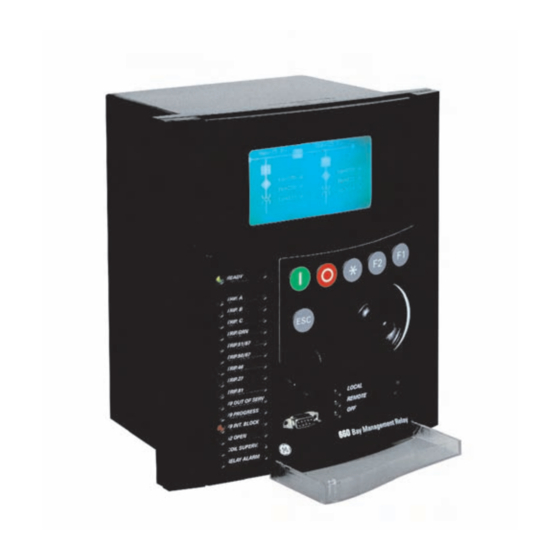
Page 23: Faceplate Display
1.4 650 HARDWARE 1 GETTING STARTED without exceeding driver capability. For larger systems, additional serial channels must be added. It is also possible to use commercially available repeaters to increase the number of relays on a single channel to more than 32. Do not use other connection configurations different to the recommended. - Page 24 View the event recorder and oscillography or fault report for correct operation of inputs, outputs and elements. If it is concluded that the relay or one of its modules is of concern, contact GE Multilin or one of its representative for prompt service.
- Page 25 1.4 650 HARDWARE 1 GETTING STARTED 1-20 F650 Digital Bay Controller GEK-113000T...
-
Page 26: Product Description
2 PRODUCT DESCRIPTION 2.1 OVERVIEW 2 PRODUCT DESCRIPTION 2.1OVERVIEW 2.1.1 F650 OVERVIEW F650 is a protection, control, monitoring, metering and registering unit, suitable for many different applications, such as main protection for distribution feeders and transmission lines, as well as backup protection for transformers, busbars, capacitor banks, etc. -
Page 27: Summary
2.2 SUMMARY 2 PRODUCT DESCRIPTION 2.2SUMMARY 2.2.1 ANSI DEVICE NUMBERS AND FUNCTIONS DEVICE NUMBER FUNCTION Synchronism Check Phase Undervoltage Auxiliary Undervoltage Directional Power 32FP Forward Power Wattmetric Zero-Sequence Directional Negative Sequence Time Overcurrent Negative Sequence Overvoltage Locked Rotor Protection against Overload by thermal model 50BF Breaker Failure Ground Instantaneous Overcurrent (measured from 4... -
Page 28: Other Device Functions
2 PRODUCT DESCRIPTION 2.2 SUMMARY 2.2.2 OTHER DEVICE FUNCTIONS INPUTS/OUTPUTS METERING COMMUNICATIONS 9 Analog Inputs: 5 current inputs (3 for phases, Metering Current for phases, ground and Front RS232 port, Two rear RS485/ 1 for ground, 1 for sensitive ground), 4 voltage sensitive ground inputs fibre optic ports, 10/100 TX and 100 FX inputs (3 for phases, 1 for busbar or auxiliary... -
Page 29: Ordering Code
2.3 ORDERING CODE 2 PRODUCT DESCRIPTION 2.3ORDERING CODE F650 units are supplied as ½ 19” rack, 6 units high, containing the following modules: power supply, CPU, I/O modules, communication modules. The required information to completely define an F650 model is shown on Table 2–1: Table 2–1: ORDERING CODE F650 DESCRIPTION... - Page 30 2 PRODUCT DESCRIPTION 2.3 ORDERING CODE SPECIAL MODELS: MOD001: 6A output contacts instead of 16A. Notes: (1) The digit selected for option G must be equal or higher than the digit selected for option F for models including boards 4 and 5. F1G5 is a valid selection and F5G1 is and invalid selection.
-
Page 31: Technical Specifications
2.4 TECHNICAL SPECIFICATIONS 2 PRODUCT DESCRIPTION 2.4TECHNICAL SPECIFICATIONS NOTE: TECHNICAL SPECIFICATIONS ARE SUBJECT TO CHANGE WITHOUT NOTICE 2.4.1 PROTECTION ELEMENTS Phase and ground units use as operation magnitude the current value received by the unit in current inputs, while the neutral unit uses the calculated current value from the three phase currents. - Page 32 2 PRODUCT DESCRIPTION 2.4 TECHNICAL SPECIFICATIONS 2.4.1.2 GROUND TIME OVERCURRENT (51G) Current Input Phasor (without harmonics) or RMS Rated current For connection to 1 or 5 A CTs. Pickup level 0.05 to 160.00 A in steps of 0.01 A Dropout level 97% to 98% of the pickup level Values at nominal frequency: Level Accuracy...
- Page 33 2.4 TECHNICAL SPECIFICATIONS 2 PRODUCT DESCRIPTION 2.4.1.4 SENSITIVE GROUND TIME OVERCURRENT (51SG) Current Input Phasor (without harmonics) or RMS Rated current For connection to 1 or 5 A CTs. Pickup level 0.005 to 16.000 A in steps of 0.001 A Dropout level 97% to 98% of the pickup level Values at nominal frequency:...
- Page 34 2 PRODUCT DESCRIPTION 2.4 TECHNICAL SPECIFICATIONS 2.4.1.6 NEUTRAL INSTANTANEOUS OVERCURRENT (50N) Current Input Fundamental Phasor (without harmonics) Pickup level 0.05 to 160.00 A in steps of 0.01 A Dropout level 97% to 98% of the pickup level Values at nominal frequency: Level Accuracy ±0.5% of the reading ±...
- Page 35 2.4 TECHNICAL SPECIFICATIONS 2 PRODUCT DESCRIPTION 2.4.1.8 ISOLATED GROUND INSTANTANEOUS OVERCURRENT (50IG) Current Input Fundamental Phasor (without harmonics) Voltage Input Fundamental Phasor (without harmonics) Current Pickup level 0.005 to 0.400 A in steps of 0.001 A Voltage Pickup level 2 to 70 V in steps of 1 V Dropout level 97 to 98% of the pickup level ±1.5% of the reading ±...
- Page 36 2 PRODUCT DESCRIPTION 2.4 TECHNICAL SPECIFICATIONS 2.4.1.10 PHASE DIRECTIONAL (67P) Directionality Forward and reverse selectable by setting Polarizing Quadrature Voltage: ABC seq: Phase A (VBC), Phase B (VCA), Phase C (VAB) ACB seq: Phase A (VCB), Phase B (VAC), Phase C (VBA) Polarizing voltage threshold 0 to 300 Vac in steps of 1 V...
- Page 37 2.4 TECHNICAL SPECIFICATIONS 2 PRODUCT DESCRIPTION 2.4.1.13 SENSITIVE GROUND DIRECTIONAL (67SG) Directionality Forward and reverse selectable by setting Polarizing Voltage Polarizing Voltage (measured or calculated, selected by setting) Operating Current Isg (measured from 5 current transformer) Polarizing Voltage threshold 0 to 300 Vac in steps of 1 V Characteristic angle -90º...
- Page 38 2 PRODUCT DESCRIPTION 2.4 TECHNICAL SPECIFICATIONS 2.4.1.16 PHASE UNDERVOLTAGE (27P) Voltage Input Fundamental Phasor of phase-to-ground or phase-to- phase voltages (selectable by setting) Pickup level 3 to 300 in steps of 1 V Dropout level 102% to 103% of the pickup level ±1% reading ±0.1% Full Scale from 10 to 275 V at Level accuracy nominal frequency...
- Page 39 2.4 TECHNICAL SPECIFICATIONS 2 PRODUCT DESCRIPTION 2.4.1.19 AUXILIARY OVERVOLTAGE (59X) Voltage Input Fundamental Phasor of the auxiliary voltage Pickup level 3 to 300 in steps of 1 V Dropout level 97% to 98% of the pickup level ±1% reading ±0.1% Full Scale from 10 to 275 V at Level accuracy nominal frequency Trip delay...
- Page 40 2 PRODUCT DESCRIPTION 2.4 TECHNICAL SPECIFICATIONS 2.4.1.22 OVERFREQUENCY (81O) Pickup level 20.00 to 65.00 Hz in steps of 0.01 Hz Dropout level Pickup - 0.03 Hz ±0.01 Hz of the reading Level accuracy Trip delay 0.00 to 900.00 s. in steps of 0.01 s Reset delay 0.00 to 900.00 s.
-
Page 41: Control
2.4 TECHNICAL SPECIFICATIONS 2 PRODUCT DESCRIPTION 2.4.1.25 WATTMETRIC ZERO-SEQUENCE DIRECTIONAL (32N) Measured Power Zero sequence Number of elements 6 (3 High level, 3 Low level) Voltage Pickup Level (VN) 2.00 to 70.00 Volts in steps of 0.01 Voltage calculated from phases if Auxiliary voltage is set to Vx Voltage Measured directly from the fourth voltage transformer if Auxiliary voltage is set to VN. -
Page 42: Pickup Level
2 PRODUCT DESCRIPTION 2.4 TECHNICAL SPECIFICATIONS 2.4.2.2 SYNCHROCHECK (25) Dead/live levels for line and bus 0.00 to 300.00 in steps of 0.01 V Maximum voltage difference 2.00 to 300.00 V in steps of 0.01 V Maximum angle difference 2.0º to 80.0º in steps of 0.1º Maximum frequency slip 10 to 5000 mHz in steps of 10 mHz Synchronism time... -
Page 43: To 900.00 S In Steps Of 0.01 S
2.4 TECHNICAL SPECIFICATIONS 2 PRODUCT DESCRIPTION 2.4.2.6 LOCKED ROTOR (48) Current Input Phasor (without harmonics) or RMS Rated current For connection to 1 or 5 A CTs. Full Load Current 0.10 to 10.00 kA in steps of 0.01 kA Pickup level 1.01 to 109.00 in steps of 0.01 x FLC Dropout level 97% to 98% of the pickup level... -
Page 44: Ms At 50 Hz Typically
2 PRODUCT DESCRIPTION 2.4 TECHNICAL SPECIFICATIONS 2.4.2.9 FREQUENCY RATE OF CHANGE df/dt trend increasing, decreasing, bi-directional df/dt pickup level 0.10 to 10.00 Hz/s in steps of 0.01 df/dt level accuracy 80 mHz/s or 3.5%, whichever is greater Overvoltage supv. 0.00 to 110.00 % in steps of 0.01 95% settling time for df/dt <... -
Page 45: Monitoring
2.4 TECHNICAL SPECIFICATIONS 2 PRODUCT DESCRIPTION 2.4.2.12 BREAKER MAINTENANCE t Breaker Counters for Phases A, B, C 0.00 to 9999.99 in steps of 0.01 (kA) Breaker Openings Counter 0 to 9999 in steps of 1 Breaker Closings Counter 0 to 9999 in steps of 1 2.4.2.13 SWITCHGEAR Switchgear 1 to16 (configurable in “relay configuration”... - Page 46 2 PRODUCT DESCRIPTION 2.4 TECHNICAL SPECIFICATIONS Data Storage: In non volatile memory (flash) without battery available through communications In volatile memory (ram) available through HMI (if selectable by setting) Format: Text in ASCII format 2.4.3.3 SNAPSHOT EVENTS Capacity: 479 scrolling events 1 ms using an internal clock of 100 µs Time-tag Timing Accuracy:...
-
Page 47: User-Programmable Elements
2.4 TECHNICAL SPECIFICATIONS 2 PRODUCT DESCRIPTION 2.4.3.6 DATA LOGGER Number of Channels: 1 to 16 Parameters Any available analog actual value Samples 1 sec., 1, 5, 10, 15, 20, 30, 60 min. Storage Capacity Fixed, 32768 measures 2.4.4 USER-PROGRAMMABLE ELEMENTS 2.4.4.1 PLC LOGIC Programming language: The logical configuration is performed using graphical functions based on the... -
Page 48: Metering
2 PRODUCT DESCRIPTION 2.4 TECHNICAL SPECIFICATIONS 2.4.4.4 USER-DEFINABLE DISPLAYS Number of configurable displays: 1 (one line diagram fully configurable). In graphical displays only Number of fixed displays: 6, Metering (in primary values), Snapshot events (all and new), Alarms, Inputs and outputs screen with test functionality for inputs and outputs. In graphical displays only Number of selectable displays: Logotype, metering or both in scrolling mode, can be selectable as default... - Page 49 2.4 TECHNICAL SPECIFICATIONS 2 PRODUCT DESCRIPTION 2.4.5.7 WAR-HOURS (POSITIVE AND NEGATIVE) ±1.0% of the reading Accuracy: ±0 to 2147 MVArh Range: Parameters: 3-phase only Update rate: 100 ms 2.4.5.8 POWER FACTOR Accuracy: 0.02 Parameters: 3-Phase and single phase 2.4.5.9 FREQUENCY Metering range from 30 Hz to 80 Hz Accuracy: For firmware version 3.00 and former ones:...
- Page 50 2 PRODUCT DESCRIPTION 2.4 TECHNICAL SPECIFICATIONS 2.4.6.2 AC VOLTAGE INPUTS VT Ratio 1.0 to 6000.0 in steps of 0.1 Rated Voltages 275 Vac Metering range: From 2 to 275 Vac Relay Burden: 0.05 VA at 120 Vac (50 or 60 Hz) Voltage Withstand: Continuous at 275 V to neutral 1 min/hr at 420 to neutral...
-
Page 51: Real Time Clock
2.4 TECHNICAL SPECIFICATIONS 2 PRODUCT DESCRIPTION 2.4.6.6 IRIG-B INPUT Amplitude modulation: DC SHIFT = Demodulated input (no carrier) Input Voltage: Input Burden: 1.5 mA Input Impedance: 3.3 kOhm Minimum Input Voltage: 2.4 V ± 24 V Maximum Input Voltage: Formats: B000 (*) B001, B002 and B003 (*) (*) Signal combinations recognized in accordance with IRIG Standard 200-95 Isolation:... -
Page 52: Control Power Supply
2 PRODUCT DESCRIPTION 2.4 TECHNICAL SPECIFICATIONS 2.4.9 CONTROL POWER SUPPLY LOW RANGE (LO) Nominal DC Voltage: 24 to 48 V Min/Max DC Voltage 19.2 / 57.6 V Note: Low range is DC only HIGH RANGE (HI) Nominal DC Voltage: 110 to 250 V Min/Max DC Voltage 88 / 300 V Nominal AC Voltage:... - Page 53 2.4 TECHNICAL SPECIFICATIONS 2 PRODUCT DESCRIPTION ® Protocols available: ModBus RTU / DNP 3.0 Typical distance: 1200 m Isolation: 2 kV CAN PORT: Rear port: CAN port in models X, Y, Z for asynchronous rear ports Type: Multimode glass F.O. port with ST connectors Fiber Wave length: 1300 nm multimode 62.5/125 µm or 50/125 µm...
-
Page 54: Optic Features
2 PRODUCT DESCRIPTION 2.4 TECHNICAL SPECIFICATIONS 2.4.11 OPTIC FEATURES Wave length: 1300nm Connector types: ST package style Fiber type: multimode 62.5/125 µm or 50/125 µm TRANSMITTER CHARACTERISTICS Parameter Min. Typ. Max. Unit Reference Output Optical Power dBm avg. Note 1 62.5/125 µm, NA = 0.275 Fiber Output Optical Power -22.5... -
Page 55: Environmental Characteristics
2.4 TECHNICAL SPECIFICATIONS 2 PRODUCT DESCRIPTION 2.4.12 ENVIRONMENTAL CHARACTERISTICS Operating temperature: - 10°C to + 60°C Storage temperature: - 40°C to + 80°C Humidity (non condensing): Altitude Up to 2000 m Installation category 2.4.13 PACKAGING AND WEIGHT Net weight: 5 kg Packaged: 6 kg Package dimensions:... -
Page 56: External Connections
2 PRODUCT DESCRIPTION 2.5 EXTERNAL CONNECTIONS 2.5EXTERNAL CONNECTIONS Figure 2–2: F650 WIRING DIAGRAM (189C4216H2) GEK-113000T F650 Digital Bay Controller 2-31... - Page 57 2.5 EXTERNAL CONNECTIONS 2 PRODUCT DESCRIPTION INPUTS / OUTPUTS CONFIGURATION FOR BOARDS F1 AND F2 SLOT F CONFIGURATION (BOARD TYPE 1) INPUTS F1 OUTPUTS F1 + CC1 79 BLOCK + CC2 50P BLOCK + CC3 51P BLOCK + CC4 67P BLOCK + CC5 50G BLOCK 27/59 PICKUP...
-
Page 58: Human Interfaces
3.1.2 ENERVISTA 650 SETUP SOFTWARE OVERVIEW This software package uses ModBus protocol, and it is designed to communicate with a single relay at a time. GE offers different communication software packages, such as GE-POWER, which can be used to communicate simultaneously with several relays. - Page 59 3.1 ENERVISTA 650 SETUP SOFTWARE INTERFACE 3 HUMAN INTERFACES. SETTINGS & ACTUAL VALUES 3.1.2.4 VIEWING TRIGGERED EVENTS While the interface is in either on-line or off-line mode, you can view and analyze data generated by triggered specified parameters, via one of the following: •...
-
Page 60: Main Screen
3 HUMAN INTERFACES. SETTINGS & ACTUAL VALUES 3.1 ENERVISTA 650 SETUP SOFTWARE INTERFACE 3.1.3 MAIN SCREEN The EnerVista 650 Setup software main window supports the following primary display components: • Title bar • Main menu bar • Main icon bar •... -
Page 61: Communication Menu
3.1 ENERVISTA 650 SETUP SOFTWARE INTERFACE 3 HUMAN INTERFACES. SETTINGS & ACTUAL VALUES 3.1.4 COMMUNICATION MENU To start communicating with the relay go to “Communication>Computer>Computer settings” section in the main EnerVista 650 Setup menu. Safety instructions must be followed before connecting the computer to the relay. Safety instructions are detailed in section 1.1.3. - Page 62 3 HUMAN INTERFACES. SETTINGS & ACTUAL VALUES 3.1 ENERVISTA 650 SETUP SOFTWARE INTERFACE 3.1.4.1 COMPUTER SETTINGS: Shows the communication parameters necessary in order to establish communication with the unit. Such as slave address, communication port, baud rate, parity, control type and startup mode. Baud rate, parity, data bits, stop bits and ModBus slave address for com2 (RS232 front port and second serial port in the rear communication board) are displayed in the default text logotype main screen.
- Page 63 3.1 ENERVISTA 650 SETUP SOFTWARE INTERFACE 3 HUMAN INTERFACES. SETTINGS & ACTUAL VALUES 3.1.5 FILE MANAGEMENT File management with EnerVista 650 Setup software: 3.1.5.1 OFF LINE MODE Run EnerVista 650 Setup Open a *.650 file (“File>Open” menu) Modify protection Settings and relay configuration Is it necessary to program...
- Page 64 3 HUMAN INTERFACES. SETTINGS & ACTUAL VALUES 3.1 ENERVISTA 650 SETUP SOFTWARE INTERFACE Table 3–1: TYPES OF FILES GENERATED BY ENERVISTA 650 SETUP SOFTWARE OPERATION MODE OFF-LINE: LOGIC CONFIGURATION FILES (*.PEP, *AUT, *.LIB) SETTINGS & CONFIGURATION FILE *.650 *.PEP *.AUT *.LIB Graphical edition container.
- Page 65 3.1 ENERVISTA 650 SETUP SOFTWARE INTERFACE 3 HUMAN INTERFACES. SETTINGS & ACTUAL VALUES 3.1.5.2 ON LINE MODE Run EnerVista 650 Setup Connect to the relay (“Communication>Computer>ON”) Modify and send to the relay protection Settings and relay configuration Is it necessary to program additional logic? Launch the Logic Configuration tool in EnerVista...
- Page 66 3 HUMAN INTERFACES. SETTINGS & ACTUAL VALUES 3.1 ENERVISTA 650 SETUP SOFTWARE INTERFACE Table 3–2: TYPES OF FILES CREATED BY ENERVISTA 650 SETUP– ONLINE OPERATION MODE LOGIC CONFIGURATION FILES (*.PEP, *.AUT, *.LIB) SETTINGS & CONFIGURATION FILE *.650 *.PEP *.AUT *.LIB Graphical edition container.
-
Page 67: Enervista 650 Setup Menu Structure
COMMUNICATION SECURITY VIEW HELP Instruction New (**) Product Setup Front Panel Computer Login user Traces Manual ModBus Change GE Multilin Open (**) System Setup Status Modem (*) Memory Password on the web About Protection User Languages Save (**) Metering Troubleshooting (*) -
Page 68: File Menu Overview
3 HUMAN INTERFACES. SETTINGS & ACTUAL VALUES 3.1 ENERVISTA 650 SETUP SOFTWARE INTERFACE 3.1.7 FILE MENU OVERVIEW Table 3–4: GENERAL OVERVIEW OF FILE MENU: FILE Create a new settings and configuration file, with the default relay New (**) settings and no configuration Open (**) Open a settings and configuration file for off-line working. - Page 69 3.1 ENERVISTA 650 SETUP SOFTWARE INTERFACE 3 HUMAN INTERFACES. SETTINGS & ACTUAL VALUES 3.1.7.1 NEW, OPEN, SAVE, SAVE AS AND CLOSE In these options, the program opens a dialog box (with default path to Files>Config program folder) where the setting and configuration files can be selected for their “off-line”...
- Page 70 3 HUMAN INTERFACES. SETTINGS & ACTUAL VALUES 3.1 ENERVISTA 650 SETUP SOFTWARE INTERFACE 3.1.7.2 CONFIG FILE (*650) CONVERTER Figure 3–6: CONFIG FILE (*650) CONVERTER MENU This tool provides automatic conversion of configuration files from a firmware version to a previous or later version. Open the source *.650 file and select the version and model to be converted to.
- Page 71 3.1 ENERVISTA 650 SETUP SOFTWARE INTERFACE 3 HUMAN INTERFACES. SETTINGS & ACTUAL VALUES 3.1.7.4 PRINTING OPTIONS (PRINT SETUP/PRINT PREVIEW/PRINT/PRINT TO FILE) The printing options are active only in off-line mode, in “File edition”, and not in on-line mode, connected with the relay. a) PRINT SETUP Option to configure the printing options and settings for the printing device.
-
Page 72: Setpoint Menu Overview
3 HUMAN INTERFACES. SETTINGS & ACTUAL VALUES 3.1 ENERVISTA 650 SETUP SOFTWARE INTERFACE 3.1.8 SETPOINT MENU OVERVIEW Table 3–5: GENERAL OVERVIEW OF SETPOINT MENU IN ENERVISTA 650 SETUP: SETPOINT Communications settings for all protocols and physical mediums. Product Setup ModBus user map definition, fault report, oscillography, data logger and demand settings. - Page 73 3.1 ENERVISTA 650 SETUP SOFTWARE INTERFACE 3 HUMAN INTERFACES. SETTINGS & ACTUAL VALUES Table 3–7: GENERAL OVERVIEW OF COMMUNICATION SETTINGS MENU: COMMUNICATION SETTINGS Serial Ports Baud rate and parity for COM1 and COM2 serial communication ports. Ethernet communication parameters for COM3 (IP Address, Netmask, Gateway IP) NOTE: The ModBus Slave address used by Ethernet ports is the one set Network (Ethernet)
- Page 74 3 HUMAN INTERFACES. SETTINGS & ACTUAL VALUES 3.1 ENERVISTA 650 SETUP SOFTWARE INTERFACE 3.1.8.3 PROTECTION ELEMENTS This option shows all the protection-grouped elements available in the relay as shown in Table 3–9:. Each of these groups includes the specific protection units of the same type. For example phase currents group includes TOC, IOC, directional units, etc.
- Page 75 3.1 ENERVISTA 650 SETUP SOFTWARE INTERFACE 3 HUMAN INTERFACES. SETTINGS & ACTUAL VALUES Table 3–10: PROTECTION ELEMENTS INCLUDED PHASE CURRENT Phase TOC High Phase time overcurrent, high level (51PH) Phase TOC Low Phase time overcurrent, low level (51PL) Phase IOC High Phase instantaneous overcurrent, high level (50PH) Phase IOC Low Phase instantaneous overcurrent, low level (50PL)
- Page 76 3 HUMAN INTERFACES. SETTINGS & ACTUAL VALUES 3.1 ENERVISTA 650 SETUP SOFTWARE INTERFACE 3.1.8.4 CONTROL ELEMENTS This option shows all the control elements available in the relay as shown in Table 3–11:. Some of the elements are grouped ones such as underfrequency, overfrequency and broken conductor. Table 3–11: GENERAL OVERVIEW OF CONTROL ELEMENTS MENU: CONTROL ELEMENTS...
- Page 77 3.1 ENERVISTA 650 SETUP SOFTWARE INTERFACE 3 HUMAN INTERFACES. SETTINGS & ACTUAL VALUES Table 3–13: GENERAL OVERVIEW OF “INPUTS/OUTPUTS>CONTACT I/O” SETTINGS MENU. CONTACT I/O Board F Board located in first slot, always connected. Board located in second slot, depends on model definition. If model is Board G type G0 there is no board in second slot.
- Page 78 3 HUMAN INTERFACES. SETTINGS & ACTUAL VALUES 3.1 ENERVISTA 650 SETUP SOFTWARE INTERFACE The following figures show an example of the default factory configuration for F650. The F650 has no default factory configuration, but a possible example could be the following: Figure 3–9: RELAY CONFIGURATION Figure 3–10: HMI CONFIGURATION GEK-113000T...
- Page 79 3.1 ENERVISTA 650 SETUP SOFTWARE INTERFACE 3 HUMAN INTERFACES. SETTINGS & ACTUAL VALUES 3.1.8.7 LOGIC CONFIGURATION This logic configuration allows creating more complex configurations, using the graphical PLC, than using the tables from Relay Configuration. For file management detailed information go to section 3.1.5. File description: *.pep: Header for Logic project: PLC project file containing the necessary information relative to the relay model, logic...
-
Page 80: Actual Values Menu Overview
3 HUMAN INTERFACES. SETTINGS & ACTUAL VALUES 3.1 ENERVISTA 650 SETUP SOFTWARE INTERFACE 3.1.9 ACTUAL VALUES MENU OVERVIEW The menu bar in the main screen of EnerVista 650 Setup software shows the ACTUAL menu option. This option concentrates and displays all the status of protection, control elements, metering, counters information, oscillography, events, fault locator, etc. - Page 81 3.1 ENERVISTA 650 SETUP SOFTWARE INTERFACE 3 HUMAN INTERFACES. SETTINGS & ACTUAL VALUES Table 3–17: ACTUAL VALUES INCLUDED IN THE PROTECTION MENU PROTECTION Protection Blocks This screen shows all the protection element blocks available. Protection elements block signals can be configured at “Setpoint>Relay Configuration >...
- Page 82 3 HUMAN INTERFACES. SETTINGS & ACTUAL VALUES 3.1 ENERVISTA 650 SETUP SOFTWARE INTERFACE Table 3–19: ACTUAL VALUES RELATED TO RECORDING FUNCTIONS IN THE RECORDS STATUS MENU: RECORD STATUS Fault Reports This menu shows the fault report status signals, as fault report trigger, fault date, fault type and location, besides the fault report number.
-
Page 83: Operations Menu Overview
3.1 ENERVISTA 650 SETUP SOFTWARE INTERFACE 3 HUMAN INTERFACES. SETTINGS & ACTUAL VALUES Options enabled only in On-line mode are marked as (*). Options enabled only in Off-line mode are marked as (**) 3.1.9.5 RECORDS The Records menu is only available in on line mode and includes the possibility to retrieve all the records available in the device. -
Page 84: Communication Menu Overview
3 HUMAN INTERFACES. SETTINGS & ACTUAL VALUES 3.1 ENERVISTA 650 SETUP SOFTWARE INTERFACE 3.1.11 COMMUNICATION MENU OVERVIEW The communication menu includes the computer screen to start communicating with the relay, the different update procedures available in device: firmware, operative system, web server and other file storing capabilities (upload and download info files to/from relay). - Page 85 Ethernet communication. Firmware is related to the relay internal program, designed by GE Multilin, which performs the protection and control functions, and which is run by the relay main microprocessor.
- Page 86 3 HUMAN INTERFACES. SETTINGS & ACTUAL VALUES 3.1 ENERVISTA 650 SETUP SOFTWARE INTERFACE Thanks to the use of a double flash memory, one with the Bootcode startup program and the operative system, and a second one with the application program (firmware), a high reliability is guaranteed when updating the unit firmware, as even if the case of a communication breakdown during the firmware upgrade process, we can retry the process for an unlimited number of times.
-
Page 87: Security Menu Overview
Table 3–27: GENERAL OVERVIEW OF HELP MENU: HELP Instructions Manual Instructions manual in the language selected in “View>Languages” menu. GE Mulitlin on the Web GE Multilin web page link. About EnerVista 650 Release version and date of EnerVista 650 Setup program. Setup... -
Page 88: Human Machine Interface (Hmi)
3 HUMAN INTERFACES. SETTINGS & ACTUAL VALUES 3.2 HUMAN MACHINE INTERFACE (HMI) 3.2 HUMAN MACHINE INTERFACE (HMI)T The HMI interface consists of several functional panels. The faceplate can be unscrewed to allow easy access to the removable modules. There is also a removable dust cover that fits over the display and other cover that protects the front RS232 Communications port and the commands buttons that can be sealed. -
Page 89: Front Led Indicators
3.2 HUMAN MACHINE INTERFACE (HMI) 3 HUMAN INTERFACES. SETTINGS & ACTUAL VALUES 3.2.2 FRONT LED INDICATORS The relay provides 16 LED indicators, 15 user programmable plus one non-configurable LED (READY) that shows if the relay is in service. Programmable LEDs are divided into groups of 5 LEDs, each of the groups having a different color. The first group of LED indicators is latched by hardware (red color ones), usually configured for trip signals. -
Page 90: Front Port And Cover Sealing System
3 HUMAN INTERFACES. SETTINGS & ACTUAL VALUES 3.2 HUMAN MACHINE INTERFACE (HMI) 3.2.3.2 COMMAND PUSH BUTTON The unit incorporates a command pushbutton located at the bottom right side of the faceplate, with three options: local, remote, and off. The first option (LOCAL) allows executing operations in local mode (HMI, front RS232 port, and rear COM2 port). -
Page 91: Text Menus
3.2 HUMAN MACHINE INTERFACE (HMI) 3 HUMAN INTERFACES. SETTINGS & ACTUAL VALUES 3.2.5 TEXT MENUS 3.2.5.1 NAVIGATION IN TEXT MENU Text menu is available for all models, this is the main menu for visualizing actual values, metering, changing settings, etc. through the HMI. - Page 92 3 HUMAN INTERFACES. SETTINGS & ACTUAL VALUES 3.2 HUMAN MACHINE INTERFACE (HMI) 3.2.5.2 TEXT MENU HIERARCHY The structure of HMI text menu is similar to the EnerVista 650 Setup in the actual values and settings (view and change) menus. The main menu shows the following options: Table 3–28: GENERAL OVERVIEW OF MAIN TEXT MENU: NAME DESCRIPTION...
- Page 93 3.2 HUMAN MACHINE INTERFACE (HMI) 3 HUMAN INTERFACES. SETTINGS & ACTUAL VALUES 3.2.5.3 ACTUAL VALUES The Actual Values menu option in HMI concentrates and displays all the status of protection, control elements, metering, counters information, oscillography, events, fault locator, etc. Table 3–29: GENERAL OVERVIEW OF ACTUAL VALUES MAIN MENU: Front Panel >...
- Page 94 3 HUMAN INTERFACES. SETTINGS & ACTUAL VALUES 3.2 HUMAN MACHINE INTERFACE (HMI) Metering > Primary Values > Current Voltage Power Energy Demand Secondary Values > Current Voltage Power Frequency Inputs/Outputs > Contact Inputs > Board F/ Board G/ Board H/ Board J Cont.
- Page 95 3.2 HUMAN MACHINE INTERFACE (HMI) 3 HUMAN INTERFACES. SETTINGS & ACTUAL VALUES Phase Current PH IOC1 HIGH A PKP (1/114) Figure 3–18: ACTUAL VALUES SCREEN DATA In the Actual Values menus are different types of data, each type of data will display its particular status type (on and off, 0 or 1, ok or fail, analog values, etc.) 3-38 F650 Digital Bay Controller...
- Page 96 3 HUMAN INTERFACES. SETTINGS & ACTUAL VALUES 3.2 HUMAN MACHINE INTERFACE (HMI) 3.2.5.4 SNAPSHOT EVENTS To enter this menu press the shuttle key when the option Snapshot events is selected in main menu (). In this menu all the snapshot events stored can be displayed. Snapshot events are changes in the relay internal status.
- Page 97 3.2 HUMAN MACHINE INTERFACE (HMI) 3 HUMAN INTERFACES. SETTINGS & ACTUAL VALUES 3.2.5.5 FAULT REPORT To enter this menu press the shuttle key when the option Fault report is selected in main menu (). This menu displays information about the last ten faults recorded in the relay. The Relay HMI allows two types of visualization for the fault reports stored in the Relay: 1.
- Page 98 3 HUMAN INTERFACES. SETTINGS & ACTUAL VALUES 3.2 HUMAN MACHINE INTERFACE (HMI) The format of the displayed screens is as follows: Select the Fault report menu in text menu If there is more than one fault record rotate the shuttle key and select the desired record to be displayed.
- Page 99 3.2 HUMAN MACHINE INTERFACE (HMI) 3 HUMAN INTERFACES. SETTINGS & ACTUAL VALUES 3.2.5.6 VIEW SETTINGS To enter this menu press the shuttle key when the option “View Settings” is selected in main menu ( ). A secondary level will be displayed with different sublevels as shown on Table 3–30:. Rotating the shuttle key, (left for moving up and right for moving down) select the next level to be displayed ( ), press the shuttle key again to enter in next level and press esc key to return to previous level if desired.
- Page 100 3 HUMAN INTERFACES. SETTINGS & ACTUAL VALUES 3.2 HUMAN MACHINE INTERFACE (HMI) MAIN SETTINGS MENU FIRST LEVEL SECOND LEVEL THIRD LEVEL Phase Directional 1 Phase Directional 2 Phase Directional 3 Thermal Model > Thermal Model 1 Thermal Model 2 Thermal Model 3 Neutral Current >...
- Page 101 3.2 HUMAN MACHINE INTERFACE (HMI) 3 HUMAN INTERFACES. SETTINGS & ACTUAL VALUES MAIN SETTINGS MENU FIRST LEVEL SECOND LEVEL THIRD LEVEL Neg. Seq. TOC 1 Neg. Seq. TOC 2 Neg. Seq. TOC 3 Voltage Elements > Phase UV > Phase UV 1 Phase UV 2 Phase UV 3 Phase OV...
- Page 102 3 HUMAN INTERFACES. SETTINGS & ACTUAL VALUES 3.2 HUMAN MACHINE INTERFACE (HMI) MAIN SETTINGS MENU FIRST LEVEL SECOND LEVEL THIRD LEVEL Setting Group Underfrequency > Underfrequency 1 Underfrequency 2 Underfrequency 3 Overfrequency > Overfrequency 1 Overfrequency 2 Overfrequency 3 Synchrocheck Autoreclose Breaker Failure VT Fuse Failure.
- Page 103 3.2 HUMAN MACHINE INTERFACE (HMI) 3 HUMAN INTERFACES. SETTINGS & ACTUAL VALUES 3.2.5.7 CHANGE SETTINGS To enter this menu press the shuttle key when the option “Change Settings” is selected in main menu. A secondary level will be displayed with different sublevels as shown on Table 3–30:. Rotating the shuttle key, (left for moving up and right for moving down) select the next level to be displayed, press the shuttle key again to enter in next level and press ESC key to return to previous level if desired.
- Page 104 3 HUMAN INTERFACES. SETTINGS & ACTUAL VALUES 3.2 HUMAN MACHINE INTERFACE (HMI) 3.2.5.8 DATE & TIME The “Date & Time” menu will show the relay date and time information in the following format: Date:Day/Month/Year Time:Hour:Minutes:Seconds To modify date and time, press the shuttle key. The relay will show the year between brackets at the top of the screen. By rotating the shuttle key, reach the desired value for the year, and press the shuttle key to select and store that value.
- Page 105 3.2 HUMAN MACHINE INTERFACE (HMI) 3 HUMAN INTERFACES. SETTINGS & ACTUAL VALUES 3.2.5.9 COMMANDS Commands are configured using EnerVista 650 Setup, and they can be executed using the pushbuttons on the relay front. Using EnerVista 650 Setup software, the user can configure up to 24 commands with a descriptive text. When executing the operation from the relay front, the operation description text will be displayed.
- Page 106 3 HUMAN INTERFACES. SETTINGS & ACTUAL VALUES 3.2 HUMAN MACHINE INTERFACE (HMI) 3.2.5.10 PASSWORDS F650 units incorporate independent passwords for protection and control, in order to prevent unauthorized keypad and display access to the relay. Settings Password: This password allows restricting access to settings changes in the relay protection elements. Commands Password: This password is required for executing operation commands through the keypad and display.
- Page 107 Cod Settings: [35c0] Cod Commands: [35c0] <Push Enter> In order to obtain the decoded password from the encrypted codes provided by the relay, it is necessary to contact GE Multilin and provide these encrypted codes. 3-50 F650 Digital Bay Controller...
- Page 108 3 HUMAN INTERFACES. SETTINGS & ACTUAL VALUES 3.2 HUMAN MACHINE INTERFACE (HMI) 3.2.5.11 SELECT MAIN SCREEN The relay display offers the possibility to select the default main screen. For this purpose, the user must access the “Select Main Screen” menu through the HMI. This menu includes the following options: Logotype This option selects as main screen the relay logotype including the firmware and boot code versions, the relay model and the communication parameters for local port COM2.
- Page 109 3.2 HUMAN MACHINE INTERFACE (HMI) 3 HUMAN INTERFACES. SETTINGS & ACTUAL VALUES 3.2.5.12 SELECT LANGUAGE Option only available for versions 1.70 or higher. The relay display offers the possibility to select the default language for the relay. For this purpose, the user must access the “Select language”...
-
Page 110: Graphic Display
3 HUMAN INTERFACES. SETTINGS & ACTUAL VALUES 3.2 HUMAN MACHINE INTERFACE (HMI) 3.2.6 GRAPHIC DISPLAY 3.2.6.1 ONE-LINE DIAGRAM In models with graphic display (F650M) default main screen is the single-line diagram. This single-line diagram can be configured using EnerVista 650 Setup software by choosing the HMI menu inside Relay Configuration (Setpoint>Relay Configuration>HMI). - Page 111 3.2 HUMAN MACHINE INTERFACE (HMI) 3 HUMAN INTERFACES. SETTINGS & ACTUAL VALUES 3.2.6.2 METERING SCREEN The Metering screen displays relay analog measures in their primary values. Available metering values are as follows: Metering Screen. Total metering 53 Phasor Ia Primary 0.000 KA Phasor Ib Primary 0.000 KA...
- Page 112 3 HUMAN INTERFACES. SETTINGS & ACTUAL VALUES 3.2 HUMAN MACHINE INTERFACE (HMI) 3.2.6.3 ALL EVENTS SCREEN This screen shows all events that have been produced in the relay. The top of the screen shows its name (All Events), and the relative and total number of events contained in the screen. All Events (1/479) This legend means that there are a total of 479 events stored in the relay, and that the cursor is located on event number 1.
- Page 113 3.2 HUMAN MACHINE INTERFACE (HMI) 3 HUMAN INTERFACES. SETTINGS & ACTUAL VALUES <DETAILS> The Details screen provides access to metering values, and date and time related with the event. The top of the screen displays a legend with the event text, followed by the date and time, the event status (ON or OFF), and the event index number related to the complete list of events in the relay, for example (1/479).
- Page 114 3 HUMAN INTERFACES. SETTINGS & ACTUAL VALUES 3.2 HUMAN MACHINE INTERFACE (HMI) L-R: Scroll. Rotating the shuttle key left (L) or right (R) moves among all the events contained in the all events screen, allowing a preview of the details for each of them. <AT>...
- Page 115 3.2 HUMAN MACHINE INTERFACE (HMI) 3 HUMAN INTERFACES. SETTINGS & ACTUAL VALUES 3.2.6.5 ALARMS PANEL Alarms panel can be viewed in all F650 models using communication software EnerVista 650 Setup, however, only models with graphic display allow access to the alarms panel from the HMI. First line shows the relative and total number of alarms existing in that screen.
- Page 116 3 HUMAN INTERFACES. SETTINGS & ACTUAL VALUES 3.2 HUMAN MACHINE INTERFACE (HMI) <ACK ALL> This option acknowledges all alarms. Alarm acknowledgement through the graphic HMI is considered as through communication port COM2, as it is considered to be Local in both cases. When an alarm has been acknowledged, a selection mark will appear to the right of its status.
- Page 117 3.2 HUMAN MACHINE INTERFACE (HMI) 3 HUMAN INTERFACES. SETTINGS & ACTUAL VALUES IO Card F. Type: 2, # IN 8, # OUT 8 Input (ON OFF) Output 0 CC1 8 Va COIL1 0 OUT1 1 CC2 9 Vb COIL1 1 OUT2 2 CC3 10 Va COIL2 2 OUT3...
- Page 118 3 HUMAN INTERFACES. SETTINGS & ACTUAL VALUES 3.2 HUMAN MACHINE INTERFACE (HMI) Esc: Exit Text. The ESC option returns to the general I/O board menu. Intro: Chg Input. Pressing the shuttle key on the blinking input, this input will be activated in emulation mode. Note: input emulation can only be executed through the TEST INPUT tool on the graphic display.
-
Page 119: Web Server 3.3.1 Home
3.3 WEB SERVER 3 HUMAN INTERFACES. SETTINGS & ACTUAL VALUES 3.3 WEB SERVER 3.3.1 HOME The web server in the F650 can be accessed running the Windows explorer, and keying http://xxx.xxx.xx.xxx, being xxx.xxx.xxx.xxx the relay IP address, which must be configured in Setpoint > Product Setup > Communication Settings >... -
Page 120: Snapshot Events
3 HUMAN INTERFACES. SETTINGS & ACTUAL VALUES 3.3 WEB SERVER 3.3.2 SNAPSHOT EVENTS The Snapshot events screen shows all Snapshot events produced in the relay. This screen is refreshed automatically every minute. The information provided in this screen includes: first, the relative event index, the lowest index corresponding to the most recent event;... -
Page 121: Control Events
3.3 WEB SERVER 3 HUMAN INTERFACES. SETTINGS & ACTUAL VALUES 3.3.3 CONTROL EVENTS The control events screen provides access to all events that have been configured in the Control Events screen inside the Relay Configuration menu of EnerVista 650 Setup. Figure 3–36: CONTROL EVENTS SCREEN Unlike the case of Snapshot events, in this screen the highest index corresponds to the most recent event. -
Page 122: Alarms
3 HUMAN INTERFACES. SETTINGS & ACTUAL VALUES 3.3 WEB SERVER 3.3.4 ALARMS The alarms screen provides access to alarms configured in the relay. As in the case of snapshot events and control events, this screen allows only to view the alarms, but not to acknowledge them. Figure 3–37: ALARMS SCREEN GEK-113000T F650 Digital Bay Controller... -
Page 123: Oscillography
Download button. The system will then open a window to allow saving the files in Comtrade format in the PC hard drive. Once the records have been saved, the system will ask if the user wants to open GE-OSC tool (Comtrade record viewer) to view the downloaded files. -
Page 124: Fault Report
3 HUMAN INTERFACES. SETTINGS & ACTUAL VALUES 3.3 WEB SERVER 3.3.6 FAULT REPORT The fault report screen provides access to the last 10 fault reports obtained by the relay. These records are stored according to an index that marks their position among all records produced in the relay, with a range from 1 to 999, returning to 1 in case of exceeding the limit of 999. -
Page 125: Data Logger
3.3 WEB SERVER 3 HUMAN INTERFACES. SETTINGS & ACTUAL VALUES 3.3.7 DATA LOGGER The data logger screen allows viewing the data logger first and last value retrieval date and allows downloading the data record files in Comtrade format, by pressing the Download option. Stored files can be viewed later using any Comtrade format viewer Figure 3–41: DATA LOGGER SCREEN 3-68... -
Page 126: Metering
3 HUMAN INTERFACES. SETTINGS & ACTUAL VALUES 3.3 WEB SERVER 3.3.8 METERING This screen includes the 53 primary metering values provided by the relay display. Figure 3–42: METERING SCREEN GEK-113000T F650 Digital Bay Controller 3-69... - Page 127 3.3 WEB SERVER 3 HUMAN INTERFACES. SETTINGS & ACTUAL VALUES 3-70 F650 Digital Bay Controller GEK-113000T...
-
Page 128: Security
4 SECURITY 4.1 ADDING USERS 4 SECURITY 4.1 ADDING USERS New users can only be added by users that have Administrator Access (or Admin Rights) . The Enable Security check box located in the Security->User Management window must be enabled. Remember: (In order to add new users and assign user rights ) •... -
Page 129: Changing Passwords
4.2 CHANGING PASSWORDS 4 SECURITY 4.2CHANGING PASSWORDS Users will be prompted to change their password after the first successful log in or through clicking Security from the toolbar, and choose Change Password. Figure 4–1: CHANGE SECURITY When the operator enters a new password for the first time, he/she should also enter a personal question that only they could answer. -
Page 130: Enabling Security
4 SECURITY 4.3 ENABLING SECURITY 4.3ENABLING SECURITY EnerVista 650 Setup Security Control is disabled by default. Users don't have to log in through user name and password after installation and are granted access as Administrator. Security Control can be enabled through Security from the tool bar when logged on as an Administrator. Click on User Management and a dialog box will show up. -
Page 131: Loging Into Enervista 650 Setup
4.4 LOGING INTO ENERVISTA 650 SETUP 4 SECURITY 4.4LOGING INTO ENERVISTA 650 SETUP Users have to log on in order to use EnerVista 650 Setup program after Security Control has been enabled. After the start up of EnerVista 650 Setup, a dialog will pop up asking for user name and password. Figure 4–3: LOGIN USER The user name field will display the last log in user name as default, in this example, TestUser. -
Page 132: Bootcode And
5 BOOTCODE AND FIRMWARE UPGRADE 5.1 INTRODUCTION 5 BOOTCODE AND FIRMWARE UPGRADE 5.1INTRODUCTION This section explains how to upgrade the F650 boot code and firmware. WARNING BEFORE PERFORMING THE UPGRADE PROCEDURE CHECK THAT BOOT AND FIRMWARE VERSION MATCH The boot code and firmware versions can be seen in the relay main screen: The relay firmware version appears after the text "F650"... -
Page 133: Communication Parameters
5.1 INTRODUCTION 5 BOOTCODE AND FIRMWARE UPGRADE NOTE A STEP LIST SUMMARY that will allow the user to control the upgrading process is included at the end of this section. It is necessary to read chapter 5 before accomplishing the F650 UPGRADE PROCEDURE. Be aware that boot program and firmware upgrades will erase all the data contained in the relay, thus it is advisable to save all the data, oscillography, events, settings and configuration files previously. - Page 134 5 BOOTCODE AND FIRMWARE UPGRADE 5.1 INTRODUCTION Gateway IP Oct4 [0 : 255] If the relay is connected to an Ethernet network, check that the IP address is unique in order to avoid collisions. In the case of relay that has upgraded previously its Bootcode (Sections 2), the IP address already has been assigned in the previous process (see Figure 5–14:).
- Page 135 5.1 INTRODUCTION 5 BOOTCODE AND FIRMWARE UPGRADE Figure 5–3: TCP/IP PROPERTIES In the IP address tab, select Advanced... (see Figure 5–3:) and add a new address in the PC that corresponds to the same LAN pattern that the relay has (in the example bellow 192.168.37.54). Figure 5–4: IP ADDRESS FOR COMPUTER Windows allows Multihosting, so it permits having as many IP addresses as desired.
-
Page 136: Boot Code Upgrade
5 BOOTCODE AND FIRMWARE UPGRADE 5.2 BOOT CODE UPGRADE 5.2BOOT CODE UPGRADE Boot code upgrade is performed using EnerVista 650 Setup. It is required that there is no active communication between the program and the relay, and that no configuration file is open. In this case, menu option Upgrade Boot code will be enabled under the EnerVista 650 Setup Communication menu. - Page 137 5.2 BOOT CODE UPGRADE 5 BOOTCODE AND FIRMWARE UPGRADE After accepting to proceed, a window will open up for selecting a temporary IP Address. It is advisable to set the IP Address that is going to be used lately in the relay for Ethernet connection. Figure 5–7: TEMPORARY IP ADDRESS SELECTION FOR BOOT UPGRADE After entering the temporary IP address, a window will open up for selecting the appropriate file from the Multilin web site or Product CD.
- Page 138 5 BOOTCODE AND FIRMWARE UPGRADE 5.2 BOOT CODE UPGRADE Then the program shows a message requiring switch off and on the relay while the progress bar is in course, to start the upgrading process. Figure 5–10: SWITCH THE RELAY OFF AND ON TO START THE BOOT PROCEDURE It is important to switch the Relay off and on again during the time shown by the progress bar;...
- Page 139 5.2 BOOT CODE UPGRADE 5 BOOTCODE AND FIRMWARE UPGRADE Figure 5–13: ERASING FLASH MEMORY Once the memory has been erased and the files upgraded in the relay, the parameters for the Ethernet communications must be set (Figure 5–14:). The requested values are the IP address and the gateway Figure 5–14: ETHERNET PARAMETERS These values should match the LAN structure in which the relay will be connected.
-
Page 140: Firmware Version Upgrade
5 BOOTCODE AND FIRMWARE UPGRADE 5.3 FIRMWARE VERSION UPGRADE 5.3FIRMWARE VERSION UPGRADE The relay settings and configuration will be lost, so it is advisable to save them to a file. For firmware revisions lower than 1.50, it is required to save calibration settings in a file before upgrading the F650 to a new firmware version. - Page 141 5.3 FIRMWARE VERSION UPGRADE 5 BOOTCODE AND FIRMWARE UPGRADE Figure 5–17: FIRMWARE SELECTION WINDOW When upgrading models with Enhanced protection and control functionality (see ordering code selection), the program will request a password in order to continue with the process. Figure 5–18: PASSWORD FOR ENHANCED MODEL UPGRADE 5-10 F650 Digital Bay Controller...
- Page 142 5 BOOTCODE AND FIRMWARE UPGRADE 5.3 FIRMWARE VERSION UPGRADE This password can be obtained placing an order with GE Multilin. The following parameters must be clearly indicated in the order: • Unit serial number • Current model option (before memory upgrade) •...
-
Page 143: Step List Summary For Versions 1.70 And Later
5.4 STEP LIST SUMMARY FOR VERSIONS 1.70 AND LATER 5 BOOTCODE AND FIRMWARE UPGRADE 5.4STEP LIST SUMMARY FOR VERSIONS 1.70 AND LATER Notice that boot program and firmware upgrade will erase all the data contained in the relay, thus it is advisable to save all the data, oscillography, events, settings and configuration files previously. -
Page 144: Commissioning
6 COMMISSIONING 6.1 VISUAL INSPECTION 6 COMMISSIONING 6.1VISUAL INSPECTION Verify that the relay has not suffered any damage during transportation, and that all screws are correctly fixed, and all relay terminal boards are in good condition. Verify that the information shown on the relay front plate corresponds to the data shown on the display, and to the requested relay model. -
Page 145: General Considerations On The Power Supply Network
6.2 GENERAL CONSIDERATIONS ON THE POWER SUPPLY NETWORK 6 COMMISSIONING 6.2GENERAL CONSIDERATIONS ON THE POWER SUPPLY NETWORK All devices running on AC current are affected by frequency. As a non-sine wave is the result of a fundamental wave plus a series of harmonics from this fundamental wave, we can infer that devices running on AC current are influenced by the applied waveform. -
Page 146: Isolation Tests
6 COMMISSIONING 6.3 ISOLATION TESTS 6.3ISOLATION TESTS During all tests, the screw located on the rear of the relay must be grounded. For verifying isolation, independent groups will be created, and voltage will be applied as follows: 2200 RMS volts will be applied progressively among all terminals in a group, short-circuited between them and the case, during one second. -
Page 147: Indicators
6.4 INDICATORS 6 COMMISSIONING 6.4INDICATORS Feed the relay and verify that when commanding a LED reset operation, all LED indicators light up and they are turned off when pressing the ESC key for more than 3 seconds. F650 Digital Bay Controller GEK-113000T... -
Page 148: Power Supply Testing
6 COMMISSIONING 6.5 POWER SUPPLY TESTING 6.5POWER SUPPLY TESTING Feed the relay with the minimum and maximum voltage. For each voltage value, verify that the alarm relay is activated when there is voltage, and it is deactivated when there is no feed. If the power supply source incorporates AC feed, this test will be performed also for VAC. -
Page 149: Communications
6.6 COMMUNICATIONS 6 COMMISSIONING 6.6COMMUNICATIONS Verify that available communication ports allow communication with the relay. Ports to be checked are as follows: Front:RS232 Rear:2 x RS485, 2 x Fiber Optic - Serial, 2 x Fiber Optic - Ethernet, 1 x RJ45 - Ethernet . A computer with EnerVista 650 Setup software and an appropriate connector must be used. -
Page 150: Verification Of Measurement
6 COMMISSIONING 6.7 VERIFICATION OF MEASUREMENT 6.7VERIFICATION OF MEASUREMENT Set the relay as follows GENERAL SETTINGS NAME VALUE UNITS RANGE PHASE CT RATIO 1.0-6000.0 GROUND CT RATIO 1.0-6000.0 STV GROUND CT RATIO 1.0-6000.0 PHASE VT RATIO 1.0-6000.0 PHASE VT CONNECTION WYE –... -
Page 151: Active, Reactive Power, And Cosj Metering
6.7 VERIFICATION OF MEASUREMENT 6 COMMISSIONING 6.7.3 ACTIVE, REACTIVE POWER, AND COSϑ METERING Equations to be applied for powers in a wye connection are as follows: POWER PER PHASE THREE-PHASE POWER P=V*I*Cosϕ P=Pa+Pb+Pc Q=V*I*Senϕ Q=Qa+Qb+Qc Apply the following current and voltage values: APPLIED VOLTAGE AND CURRENT VALUES PER PHASE PHASE A PHASE B... -
Page 152: Inputs And Outputs
6 COMMISSIONING 6.8 INPUTS AND OUTPUTS 6.8INPUTS AND OUTPUTS During all tests, the screw on the rear of the relay must be grounded. 6.8.1 DIGITAL INPUTS During this test, the user will determine the activation/deactivation points for every input in the relay for the set voltage value of 30 Volts. -
Page 153: Contact Outputs
6.8 INPUTS AND OUTPUTS 6 COMMISSIONING 6.8.2 CONTACT OUTPUTS The correct activation of every output will be verified. For every output, activation command of a single contact must be given, and then verify that only that contact is activated. Go to EnerVista 650 Setup Software (Setpoint>Inputs/Outputs>Force Outputs). For switched contacts, the change of state of both contacts shall be verified. -
Page 154: Connections For Testing Protection Elements
6 COMMISSIONING 6.9 CONNECTIONS FOR TESTING PROTECTION ELEMENTS 6.9CONNECTIONS FOR TESTING PROTECTION ELEMENTS Connect current sources to the relay according to the wiring diagram. Current and voltage input terminals are as follows: PHASE CONNECTIONS Current B1-B2 B3-B4 B5-B6 B9-B10 B11-B12 Voltage A5-A6 A7-A8... -
Page 155: Instantaneous Overcurrent (50Ph, 50Pl, 50N, 50G Y 50Sg)
6.10 INSTANTANEOUS OVERCURRENT (50PH, 50PL, 50N, 50G Y 50SG) 6 COMMISSIONING 6.10INSTANTANEOUS OVERCURRENT (50PH, 50PL, 50N, 50G Y 50SG) Set the relay to trip for the protection element being tested. Configure any of the outputs to be enabled only by the protection element being tested. -
Page 156: Time Overcurrent (51Ph, 51Pl, 51N, 51G And 46)
6 COMMISSIONING 6.11 TIME OVERCURRENT (51PH, 51PL, 51N, 51G AND 46) 6.11 TIME OVERCURRENT (51PH, 51PL, 51N, 51G AND 46) Set the relay to trip for the protection element being tested. Configure any of the outputs to be activated only by the protection element being tested. -
Page 157: Directional Elements (67P, 67N, 67G, 67Sg)
6.12 DIRECTIONAL ELEMENTS (67P, 67N, 67G, 67SG) 6 COMMISSIONING 6.12DIRECTIONAL ELEMENTS (67P, 67N, 67G, 67SG) In order to test directional units in the relay, instantaneous trips will be commanded. Two points will be tested, per phase, test element. In order to test the directional units, configure (in the "Setpoint > Relay Configuration > Protection Elements" screen of the EnerVista 650 Setup program), some overcurrent element to be supervised by a directional unit. - Page 158 6 COMMISSIONING 6.12 DIRECTIONAL ELEMENTS (67P, 67N, 67G, 67SG) Apply the following tests: ELEMENTS PHASE UNDER TEST POLARIZATION PHASE ELEMENT TRIP CHANNEL MAGNITUDE CHANNEL MAGNITUDE 50N/67N 0º 60 V 0º 60 V 180º 0º 0º 0º VIII 0º GEK-113000T F650 Digital Bay Controller 6-15...
-
Page 159: Element
6.12 DIRECTIONAL ELEMENTS (67P, 67N, 67G, 67SG) 6 COMMISSIONING 6.12.3 67G ELEMENT Activate only protection elements 50G and 67G and set the relay as follows: 67G SETTINGS 50G SETTINGS Function ENABLED Function ENABLED -45 Deg Input PHASOR (DFT) Direction FORWARD Pickup Level 0.50 A Polarization... -
Page 160: 67Sg Element
6 COMMISSIONING 6.12 DIRECTIONAL ELEMENTS (67P, 67N, 67G, 67SG) 6.12.4 67SG ELEMENT Activate only protection elements 50SG and 67SG and set the relay as follows: 67SG SETTINGS 50SG SETTINGS Function ENABLED Function ENABLED -45 Deg Input PHASOR (DFT) Direction FORWARD Pickup Level 0.50 A Polarization... -
Page 161: Undervoltage Elements (27P, 27X)
6.13 UNDERVOLTAGE ELEMENTS (27P, 27X) 6 COMMISSIONING 6.13UNDERVOLTAGE ELEMENTS (27P, 27X) 6.13.1 27P ELEMENT Set the relay to trip for the protection element being tested. Configure any of the outputs to be activated only by the protection element being tested. Set the relay as follows: PHASE UV (27P) Function... -
Page 162: Overvoltage Elements (59P, 59X, 59Nh, 59Nl, 47)
6 COMMISSIONING 6.14 OVERVOLTAGE ELEMENTS (59P, 59X, 59NH, 59NL, 47) 6.14OVERVOLTAGE ELEMENTS (59P, 59X, 59NH, 59NL, 47) 6.14.1 59P ELEMENT Set the relay to trip for the protection element being tested. Configure any of the outputs to be activated only by the protection element being tested. -
Page 163: 59Nh And 59Nl Elements
6.14 OVERVOLTAGE ELEMENTS (59P, 59X, 59NH, 59NL, 47) 6 COMMISSIONING 6.14.3 59NH AND 59NL ELEMENTS Set the relay as follows GENERAL SETTINGS Auxiliary Voltage NEUTRAL OV HIGH/LOW (59NH/59NL) Function ENABLED Pickup Level 120 V Trip Delay 2.00 Reset Delay 0.00 Apply voltage as indicated on the table under the overvoltage setting level and verify that the relay does not trip. -
Page 164: Element - Neg Seq Ov
6 COMMISSIONING 6.14 OVERVOLTAGE ELEMENTS (59P, 59X, 59NH, 59NL, 47) 6.14.4 47 ELEMENT - NEG SEQ OV Set the relay as follows: NEG SEQ OV (47) Function ENABLED Pickup Level 50 V Trip Delay 2.00 Reset Delay 0.00 Apply voltage as indicated on the table under the overvoltage setting level and verify that the relay does not trip. Verify that the relay trips for the set voltage (with an admissible error of 5%). -
Page 165: Frequency Elements (81O/81U)
6.15 FREQUENCY ELEMENTS (81O/81U) 6 COMMISSIONING 6.15 FREQUENCY ELEMENTS (81O/81U) Set the relay to trip for the protection element being tested. Configure any of the outputs to be activated only by the protection element being tested. Set the relay as follows: GENERAL SETTINGS Nominal Frequency 50 Hz... -
Page 166: Recloser
6 COMMISSIONING 6.16 RECLOSER (79) 6.16 RECLOSER (79) Set protection element 79 as follows: RECLOSER Function ENABLED Max Number Shots Dead Time 1 2.10 sec Dead Time 2 4.10 sec Dead Time 3 6.10 sec Dead Time 4 8.10 sec Reclaim Time 3.00 sec Cond. -
Page 167: Recloser Status
6.16 RECLOSER (79) 6 COMMISSIONING 6.16.2 RECLOSER STATUS BLOCK Activate the block input and verify that the recloser is in BLOCK status. Close the breaker and wait for 5 seconds. Command a trip and verify that the breaker opens but there is no reclose. INHIBITION BY RECLOSING CONDITIONS Close the breaker and wait for 5 seconds. -
Page 168: Thermal Image Element
6 COMMISSIONING 6.17 THERMAL IMAGE ELEMENT (49) 6.17 THERMAL IMAGE ELEMENT (49) Disable all protection elements except for Thermal Model (49). Set the pickup level to 2 A. Set the time constant τ1 to 3 minutes and τ2 to one time τ1. Apply currents of 2, 5, and 10 times the tap and ensure that the operation times are within the range described on the following table: RATED CURRENT (A) - Page 169 6.17 THERMAL IMAGE ELEMENT (49) 6 COMMISSIONING 6-26 F650 Digital Bay Controller GEK-113000T...
- Page 170 7 FREQUENTLY ASKED QUESTIONS 7.1 COMMUNICATIONS 7 FREQUENTLY ASKED QUESTIONS 7.1COMMUNICATIONS Does the F650 support DNP and ModBus over the Ethernet port? F650 units support both protocols over both the asynchronous serial ports and the Ethernet LAN synchronous port using TCP/IP and UDP/IP layers over the Ethernet. Does this equipment support dual IP access? Yes, it supports two independent IP addresses in aliasing mode.
- Page 171 7.1 COMMUNICATIONS 7 FREQUENTLY ASKED QUESTIONS Q12. May I connect URs and F650s to the same Ethernet? A12. Yes, either in cable as in fiber, or even mix them. Q13. How do I connect with fiber 10-BASE-FL UR relays with 100-BASE-FX F650 relays? A13.
- Page 172 7 FREQUENTLY ASKED QUESTIONS 7.2 PROTECTION 7.2PROTECTION Does the F650 support IRIG-B signals? Which type and accuracy? How many units may be connected to the same source? Yes, the F650 includes an IRIG-B input for all models, including the basic ones. It uses DC level format B.
- Page 173 7.3 CONTROL AND HMI 7 FREQUENTLY ASKED QUESTIONS 7.3CONTROL AND HMI What is the difference between Get/Send info from/to relay and Upload/Download info files to/from relay? Get/Send are used for settings and configuration storage that although both are in a unique file, are sent separately in two times.
- Page 174 7 FREQUENTLY ASKED QUESTIONS 7.4 RELAY CONFIGURATION 7.4RELAY CONFIGURATION Does the "Service" contact on the Power Supply board cover all possible failures or do I have to create an output on the I/O board that includes all the internal errors I can access in the logic? The power supply ready contact only monitor hardware failures in the power supply, to monitor the internal error of the unit it is necessary to configure a virtual output to and the assign it to the device desired (contact output, LED, etc.).
- Page 175 7.4 RELAY CONFIGURATION 7 FREQUENTLY ASKED QUESTIONS F650 Digital Bay Controller GEK-113000T...
- Page 176 8 F650TROUBLESHOOTING GUIDE 8.1 SYMPTOMS AND RECOMMENDED ACTIONS 8 F650TROUBLESHOOTING GUIDE 8.1SYMPTOMS AND RECOMMENDED ACTIONS F650 units have been designed and verified using the most advanced and reliable equipment. Mounting and testing automation ensure a high consistency of the final product. Before sending a unit back to the factory, we strongly recommend you follow the recommendations below.
- Page 177 8.1 SYMPTOMS AND RECOMMENDED ACTIONS 8 F650TROUBLESHOOTING GUIDE CATEGORY SYMPTOM POSSIBLE CAUSE RECOMMENDED ACTION Communications Cannot see properly Disabled Java options in Advanced 1.- Go to Advanced in Internet options the web server in F650 Internet Explorer properties or high for Internet explorer and select the with Windows XP.
- Page 178 8 F650TROUBLESHOOTING GUIDE 8.1 SYMPTOMS AND RECOMMENDED ACTIONS CATEGORY SYMPTOM POSSIBLE CAUSE RECOMMENDED ACTION Bootware The relay gets stuck at -The Ethernet connection does not Serial communications work properly “Sending file work properly. and the flash memory has been imagen_kernel...” erased but ethernet communication does not work properly, check: •...
- Page 179 8.1 SYMPTOMS AND RECOMMENDED ACTIONS 8 F650TROUBLESHOOTING GUIDE • EnerVista 650 Setup program do not Firmware During the upgrading - Communication problems during the procces models upgrade procecure. ask for a password if the relay model is with 61850 -The procedure been IEC61850...
- Page 180 APPENDIX A A.1 LOGIC OPERANDS APPENDIX A LOGIC OPERANDSA.1LOGIC OPERANDS OPERANDS - F650 - MODEL FX - GX INTERNAL SYSTEM STATUS AUTOCHECK INTERNAL STATES (CRITICAL) DSP Communication Error: (0) Rignt communications DSP COMM ERROR between DSP and main processor; (1) Communication Error between DSP and main processor Magnetic Module Error: (0) Right Communication MAGNETIC MODULE...
- Page 181 A.1 LOGIC OPERANDS APPENDIX A USER MAP STATUS User map status: (0) Not configured ; (1) Configured FACTORY Calibration status (0) Not calibrated ; (1) Relay calibrated CALIBRATION FLEXCURVE A STATUS User curve A: (0) Not configured (1) Configured FLEXCURVE B STATUS User curve B: (0) Not configured (1) Configured FLEXCURVE C STATUS User curve C: (0) Not configured (1) Configured Other internal states FLEXCURVE D STATUS User curve D: (0) Not configured (1) Configured...
- Page 182 APPENDIX A A.1 LOGIC OPERANDS VIRTUAL OUTPUT 000 Configurable logic output 000 VIRTUAL OUTPUT 001 Configurable logic output 001 Configurable Logic Outputs (512 elements) VIRTUAL OUTPUT 511 Configurable logic output 511 Operation bit 001: (0) the configured time expires or OPERATION BIT 1 when success conditions are met;(1) operation 1 is executed and interlocks are fulfilled.
- Page 183 A.1 LOGIC OPERANDS APPENDIX A OPERANDS - F650 - MODEL FX - GX INTERNAL SYSTEM STATUS (CONT.) CONTROL EVENT 1 Control Event 1 Activation Bit CONTROL EVENT 2 Control Event 2 Activation Bit Control Event Bits (128 elements) CONTROL EVENT 128 Control Event 128 Activation Bit LATCHED VIRT IP 1 Latched virtual input 1...
- Page 184 APPENDIX A A.1 LOGIC OPERANDS OPERANDS - F650 - MODEL FX - GX INTERNAL SYSTEM STATUS (CONT.) CONT IP_X_CC1 Input 1 (CC1) in Board X CONT IP_X_CC2 Input 2 (CC2) in Board X Contact Inputs Type 4 Board CONT IP_X_CC32 Input 32 (CC32) in Board X CONT IP_X_CC1 Input 1 (CC1) in Board X...
- Page 185 A.1 LOGIC OPERANDS APPENDIX A OPERANDS - F650 - MODEL FX - GX INTERNAL SYSTEM STATUS (CONT.) SWITCH 1 A STATUS Contact logic output type A from switchgear Function 1 SWITCH 1 B STATUS Contact logic output type B from switchgear Function 1 SWITCH 2 A STATUS Contact logic output type A from switchgear Function 2 Switchgear outputs (16 elements)
- Page 186 APPENDIX A A.1 LOGIC OPERANDS OPERANDS - F650 - MODEL FX - GX INTERNAL SYSTEM STATUS (CONT.) Ready LED: (0-Red) Relay out of service, protection READY LED OUT OF ORDER (1-Green) Relay in service; protection READY Programmable LED 1 status: Red colour. Latched by LED 1 hardware.
- Page 187 A.1 LOGIC OPERANDS APPENDIX A OPERANDS - F650 - MODEL FX - GX INTERNAL SYSTEM STATUS (CONT.) I Key I key operation (Programmable signal via PLC) O Key O key operation (Programmable signal via PLC) Programmable Keypad Status (HMI) * Key * key operation (Programmable signal via PLC) F1 Key F1 key operation (Programmable signal via PLC)
- Page 188 APPENDIX A A.1 LOGIC OPERANDS OPERANDS - F650 - MODEL FX - GX INTERNAL SYSTEM STATUS (CONT.) Oscillography Digital channel 1 : (1) Active ; (0) Not OSC DIG CHANNEL 1 Active Oscillography Digital channel 2 : (1) Active ; (0) Not OSC DIG CHANNEL 2 Active Oscillography Digital channel 3 : (1) Active ;...
- Page 189 A.1 LOGIC OPERANDS APPENDIX A OPERANDS - F650 - MODEL FX - GX INTERNAL SYSTEM STATUS (CONT.) GROUP 1 ACT ON Group 1 activation, and deactivation of groups 2 & 3 GROUP 2 ACT ON Group 2 activation, and deactivation of groups 1 & 3 GROUP 3 ACT ON Group 3 activation, and deactivation of groups 1 &...
- Page 190 APPENDIX A A.1 LOGIC OPERANDS OPERANDS - F650 - MODEL FX - GX INTERNAL SYSTEM STATUS (CONT.) Phase instantaneous overcurrent element block Group 1 PH IOC1 HIGH A BLK phase A Phase instantaneous overcurrent element block Group 1 PH IOC1 HIGH B BLK phase B Phase instantaneous overcurrent element block Group 1 PH IOC1 HIGH C BLK...
- Page 191 A.1 LOGIC OPERANDS APPENDIX A OPERANDS - F650 - MODEL FX - GX INTERNAL SYSTEM STATUS (CONT.) Phase instantaneous overcurrent element block Group 3 PH IOC3 HIGH C BLK phase C Phase instantaneous overcurrent element pickup high PH IOC3 HIGH A PKP level Group 3 phase A Phase instantaneous overcurrent element operation PH IOC3 HIGH A OP...
- Page 192 APPENDIX A A.1 LOGIC OPERANDS OPERANDS - F650 - MODEL FX - GX INTERNAL SYSTEM STATUS (CONT.) Phase instantaneous overcurrent element block Low PH IOC1 LOW A BLK level Group 1 phase A Phase instantaneous overcurrent element block Low PH IOC1 LOW B BLK level Group 1 phase B Phase instantaneous overcurrent element block Low PH IOC1 LOW C BLK...
- Page 193 A.1 LOGIC OPERANDS APPENDIX A OPERANDS - F650 - MODEL FX - GX INTERNAL SYSTEM STATUS (CONT.) Phase instantaneous overcurrent element block Low PH IOC3 LOW B BLK level Group 3 phase B Phase instantaneous overcurrent element block Low PH IOC3 LOW C BLK level Group 3 phase C Phase instantaneous overcurrent element pickup low PH IOC3 LOW A PKP...
- Page 194 APPENDIX A A.1 LOGIC OPERANDS OPERANDS - F650 - MODEL FX - GX INTERNAL SYSTEM STATUS (CONT.) Ground instantaneous overcurrent element block Group GROUND IOC1 BLOCK Ground instantaneous overcurrent element pickup GROUND IOC1 PKP Group 1 Ground instantaneous overcurrent element operation GROUND IOC1 OP (trip) Group 1 Ground instantaneous overcurrent element block Group...
- Page 195 A.1 LOGIC OPERANDS APPENDIX A OPERANDS - F650 - MODEL FX - GX INTERNAL SYSTEM STATUS (CONT.) Isolated ground instantaneous overcurrent element ISOLATED GND1 BLK block Group 1 Isolated ground instantaneous overcurrent element ISOLATED GND1 PKP pickup Group 1 Isolated ground instantaneous overcurrent element ISOLATED GND1 OP operation (trip) Group 1 Isolated ground instantaneous overcurrent element...
- Page 196 APPENDIX A A.1 LOGIC OPERANDS OPERANDS - F650 - MODEL FX - GX INTERNAL SYSTEM STATUS (CONT.) PH TOC1 HIGH A BLK Phase timed overcurrent element block Group 1 phase A PH TOC1 HIGH B BLK Phase timed overcurrent element block Group 1 phase B Phase timed overcurrent element block Group 1 phase PH TOC1 HIGH C BLK Phase timed overcurrent element pickup Group 1 phase...
- Page 197 A.1 LOGIC OPERANDS APPENDIX A OPERANDS - F650 - MODEL FX - GX INTERNAL SYSTEM STATUS (CONT.) Phase timed overcurrent element pickup Group 3 phase PH TOC3 HIGH A PKP Phase timed overcurrent element operation (trip) Group PH TOC3 HIGH A OP 3 phase A Phase timed overcurrent element pickup Group 3 phase PH TOC3 HIGH B PKP...
- Page 198 APPENDIX A A.1 LOGIC OPERANDS OPERANDS - F650 - MODEL FX - GX INTERNAL SYSTEM STATUS (CONT.) Phase timed overcurrent element operation (trip) low PH TOC2 LOW B OP level Group 2 phase B Phase timed overcurrent element pickup low level Group PH TOC2 LOW C PKP 2 phase C Phase timed overcurrent element operation (trip) low...
- Page 199 A.1 LOGIC OPERANDS APPENDIX A OPERANDS - F650 - MODEL FX - GX INTERNAL SYSTEM STATUS (CONT.) GROUND TOC1 BLOCK Ground timed overcurrent element block Group 1 GROUND TOC1 PKP Ground timed overcurrent element pickup Group 1 Ground timed overcurrent element operation (trip) Group GROUND TOC1 OP GROUND TOC2 BLOCK Ground timed overcurrent element block Group 2 GROUND TOC2 PKP...
- Page 200 APPENDIX A A.1 LOGIC OPERANDS OPERANDS - F650 - MODEL FX - GX INTERNAL SYSTEM STATUS (CONT.) THERMAL1 BLOCK Thermal image block Group 1 THERMAL1 A RST Thermal image phase A Group 1 element reset THERMAL1 B RST Thermal image phase B Group 1 element reset THERMAL1 C RST Thermal image phase C Group 1 element reset THERMAL1 ALARM...
- Page 201 A.1 LOGIC OPERANDS APPENDIX A OPERANDS - F650 - MODEL FX - GX INTERNAL SYSTEM STATUS (CONT.) PHASE DIR1 BLK INP Phase directional block Group 1 PHASE DIR1 BLOCK A Phase directional element block Group 1 Phase A PHASE DIR1 A OP Phase directional element operation Group 1 Phase A PHASE DIR1 BLOCK B Phase directional element block Group 1 Phase B...
- Page 202 APPENDIX A A.1 LOGIC OPERANDS OPERANDS - F650 - MODEL FX - GX INTERNAL SYSTEM STATUS (CONT.) GROUND DIR1 BLK INP Ground directional element block input signal Group 1 GROUND DIR1 BLOCK Ground directional element blocked Group 1 GROUND DIR1 OP Ground directional element operation Group 1 GROUND DIR2 BLK INP Ground directional element block input signal Group 2 Ground Directional...
- Page 203 A.1 LOGIC OPERANDS APPENDIX A OPERANDS - F650 - MODEL FX - GX INTERNAL SYSTEM STATUS (CONT.) PHASE UV1 CA OP Undervoltage element operation CA Group 1 PHASE UV1 PKP Pickup of any of the above mentioned elements PHASE UV1 OP Operation of any of the above mentioned elements PHASE UV2 BLOCK Phase undervoltage element block Group 2...
- Page 204 APPENDIX A A.1 LOGIC OPERANDS OPERANDS - F650 - MODEL FX - GX INTERNAL SYSTEM STATUS (CONT.) PHASE OV1 BLOCK Phase overvoltage element block Group 1 PHASE OV1 AB PKP Overvoltage element pickup AB Group 1 PHASE OV1 AB OP Overvoltage element operation AB Group 1 PHASE OV1 BC PKP Overvoltage element pickup BC Group 1...
- Page 205 A.1 LOGIC OPERANDS APPENDIX A OPERANDS - F650 - MODEL FX - GX INTERNAL SYSTEM STATUS (CONT.) NEUTRAL OV1 HIGH Neutral overvoltage element block high level Group 1 NEUTRAL OV1 HIGH Neutral overvoltage element pickup high level Group 1 NEUTRAL OV1 HIGH Neutral overvoltage element operation high level Group NEUTRAL OV2 HIGH Neutral overvoltage element block high level Group 2...
- Page 206 APPENDIX A A.1 LOGIC OPERANDS OPERANDS - F650 - MODEL FX - GX INTERNAL SYSTEM STATUS (CONT.) AUXILIARY OV1 BLOCK Auxiliary overvoltage element block Group 1 AUXILIARY OV1 PKP Auxiliary Overvoltage element pickup Group 1 AUXILIARY OV1 OP Auxiliary overvoltage element operation Group 1 AUXILIARY OV2 BLOCK Auxiliary overvoltage element block Group 2 Auxiliary OV AUXILIARY OV2 PKP...
- Page 207 A.1 LOGIC OPERANDS APPENDIX A OPERANDS - F650 - MODEL FX - GX INTERNAL SYSTEM STATUS (CONT.) UNDERFREQ1 BLOCK Underfrequency element block Group 1 UNDERFREQ1 PKP Underfrequency element pickup Group 1 UNDERFREQ1 OP Underfrequency element operation Group 1 UNDERFREQ2 BLOCK Underfrequency element block Group 2 Underfrequency UNDERFREQ2 PKP...
- Page 208 APPENDIX A A.1 LOGIC OPERANDS OPERANDS - F650 - MODEL FX - GX INTERNAL SYSTEM STATUS (CONT.) FWD PWR1 BLOCK Forward power element block Group 1 FWD PWR1 STG1 PKP Forward Power element pickup level 1 Group 1 FWD PWR1 STG1 OP Forward Power element operation level 1 Group 1 FWD PWR1 STG2 PKP Forward Power element pickup level 2 Group 1 FWD PWR1 STG2 OP...
- Page 209 A.1 LOGIC OPERANDS APPENDIX A OPERANDS - F650 - MODEL FX - GX INTERNAL SYSTEM STATUS (CONT.) Synchrocheck BLK INP Synchronism element block Synchronsim condition (Dv, Dj and Df are within the set Synchrocheck OP range) Closing permission for the synchronism element: SYNCHK CLOSE PERM (SYNCHK OP) OR (SYNCHK CON OP) Synchrocheck COND...
- Page 210 APPENDIX A A.1 LOGIC OPERANDS OPERANDS - F650 - MODEL FX - GX INTERNAL SYSTEM STATUS (CONT.) AR BLOCK BY LEVEL Recloser – Block by level Autorecloser AR BLOCK BY PULSE Recloser – Block by command (pulse) Default Channel (not used) Default Channel Channel not used DIR PWR1 BLOCK...
- Page 211 A.1 LOGIC OPERANDS APPENDIX A OPERANDS - F650 - MODEL FX - GX INTERNAL SYSTEM STATUS (CONT.) PulseCntr Value 1 Pulse counter element value Group 1 PulseCntr Value 2 Pulse counter element value Group 2 PulseCntr Value 8 Pulse counter element value Group 8 Pulse Counters PulseCntr Freeze 1 Pulse counter element freeze value Group 1...
- Page 212 APPENDIX A A.1 LOGIC OPERANDS OPERANDS - F650 - MODEL FX - GX INTERNAL SYSTEM STATUS (CONT.) 32N1 HIGH BLOCK wattmetric Ground Fault Element Block High Level Group 1 32N1 HIGH PKP wattmetric Ground Fault Element Global Pickup (current, voltage and power) High Level Group 1 32N1 HIGH OC PKP wattmetric Ground Fault Element Overcurrent Pickup High Level Group 1...
- Page 213 A.1 LOGIC OPERANDS APPENDIX A OPERANDS - F650 - MODEL FX - GX INTERNAL SYSTEM STATUS (CONT.) 32N1 LOW BLOCK wattmetric Ground Fault Element Block Low Level Group 1 32N1 LOW PKP wattmetric Ground Fault Element Global Pickup (current, voltage and power) Low Level Group 1 32N1 LOW OC PKP wattmetric Ground Fault Element Overcurrent Pickup Low Level Group 1...
- Page 214 APPENDIX A A.1 LOGIC OPERANDS OPERANDS - F650 - MODEL FX - GX INTERNAL SYSTEM STATUS (CONT.) 1 output on. Remote Output DNA 1 Operation (GSSE/ DNA 1 GOOSE) 1 output on. Remote Output DNA 2 Operation (GSSE/ DNA 2 GOOSE) 1 output on.
- Page 215 A.1 LOGIC OPERANDS APPENDIX A A-36 F650 Digital Bay Controller GEK-113000T...
- Page 216 APPENDIX B B.1 FACTORY DEFAULT LOGIC APPENDIX B FACTORY DEFAULT LOGICB.1 FACTORY DEFAULT LOGIC LEDS AND OUTPUTS BOOLEANS PICKUPS PH TOC1 HIGH PKP VO_053_51P_PKP inOR1 outOR1 PH TOC2 HIGH PKP inOR2 PH TOC3 HIGH PKP inOR3 PH TOC1 LOW PKP inOR4 inOR5 PH TOC2 LOW PKP...
- Page 217 B.1 FACTORY DEFAULT LOGIC APPENDIX B GROUND TOC1 PKP VO_049_51G_PKP inOR1 outOR1 GROUND TOC2 PKP inOR2 GROUND TOC3 PKP inOR3 GROUND IOC1 PKP VO_048_50G_PKP inOR1 outOR1 GROUND IOC2 PKP inOR2 GROUND IOC3 PKP inOR3 VO_049_51G_PKP VO_009_GROUND_OVERCURRENT_PKP VO_048_50G_PKP SENS GND TOC1 PKP VO_003_51SG_PKP inOR1 outOR1...
- Page 218 APPENDIX B B.1 FACTORY DEFAULT LOGIC PHASE UV1 PKP VO_045_27P_PKP inOR1 outOR1 PHASE UV2 PKP inOR2 PHASE UV3 PKP inOR3 PHASE OV1 PKP VO_046_59P_PKP inOR1 outOR1 PHASE OV2 PKP inOR2 PHASE OV3 PKP inOR3 NEUTRAL OV1 HIGH PKP VO_012_59NH_PKP inOR1 outOR1 NEUTRAL OV2 HIGH PKP inOR2...
- Page 219 B.1 FACTORY DEFAULT LOGIC APPENDIX B OVERFREQ1 PKP VO_054_81O_PKP inOR1 outOR1 OVERFREQ2 PKP inOR2 OVERFREQ3 PKP inOR3 UNDERFREQ1 PKP VO_055_81U_PKP inOR1 outOR1 UNDERFREQ2 PKP inOR2 UNDERFREQ3 PKP inOR3 FREQUENCY PICKUPS FREQ RATE1 PKP VO_052_81DF-DT PKP inOR1 outOR1 FREQ RATE2 PKP inOR2 FREQ RATE3 PKP inOR3...
- Page 220 APPENDIX B B.1 FACTORY DEFAULT LOGIC 32N1 HIGH PKP VO_092_32N_HIGH_PKP inOR1 outOR1 32N2 HIGH PKP inOR2 WATTIMETRIC WATTIMETRIC 32N3 HIGH PKP GROUND GROUND inOR3 FAULT PKP FAULT PKP VO_093_32N_LOW_PKP 32N1 LOW PKP inOR1 outOR1 32N2 LOW PKP inOR2 32N3 LOW PKP inOR3 VO_023_FORWARD_POWER_PKP VO_026_POWER_PKP...
- Page 221 B.1 FACTORY DEFAULT LOGIC APPENDIX B TRIPS PH TOC1 HIGH OP VO_057_51P_TRIP PH TOC2 HIGH OP inOR1 outOR1 inOR2 PH TOC3 HIGH OP inOR3 PH TOC1 LOW OP inOR4 inOR5 PH TOC2 LOW OP inOR6 PH TOC3 LOW OP PH IOC1 HIGH OP VO_058_50PH_TRIP inOR1 outOR1...
- Page 222 APPENDIX B B.1 FACTORY DEFAULT LOGIC GROUND IOC1 OP VO_068_50G_TRIP inOR1 outOR1 GROUND IOC2 OP inOR2 GROUND IOC3 OP inOR3 VO_067_51G_TRIP VO_069_GROUND_OVERCURRENT_TRIP VO_068_50G_TRIP SENS GND TOC1 OP VO_070_51SG_TRIP inOR1 outOR1 SENS GND TOC2 OP inOR2 SENS GND TOC3 OP inOR3 SENS GND IOC1 OP VO_071_50SG_TRIP inOR1...
- Page 223 B.1 FACTORY DEFAULT LOGIC APPENDIX B PHASE UV1 OP VO_073_27P_TRIP inOR1 outOR1 PHASE UV2 OP inOR2 PHASE UV3 OP inOR3 PHASE OV1 OP VO_074_59P_TRIP inOR1 outOR1 PHASE OV2 OP inOR2 PHASE OV3 OP inOR3 NEUTRAL OV1 HIGH OP VO_075_59NH_TRIP inOR1 outOR1 NEUTRAL OV2 HIGH OP inOR2...
- Page 224 APPENDIX B B.1 FACTORY DEFAULT LOGIC OVERFREQ1 OP VO_080_81O_TRIP inOR1 outOR1 OVERFREQ2 OP inOR2 OVERFREQ3 OP inOR3 UNDERFREQ1 OP VO_081_81U_TRIP inOR1 outOR1 UNDERFREQ2 OP inOR2 UNDERFREQ3 OP inOR3 FREQUENCY TRIPS FREQ RATE1 OP VO_060_81DF-DT OP inOR1 outOR1 FREQ RATE2 OP inOR2 FREQ RATE3 OP inOR3...
- Page 225 B.1 FACTORY DEFAULT LOGIC APPENDIX B _ _ _ VO_024_FORWARD_POWER_TRIP VO_028_POWER_TRIP inOR1 outOR1 VO_027_DIRECTIONAL_POWER_TRIP POWER inOR2 VO_096_32N_HIGH_TRIP inOR3 VO_097_32N_LOW_TRIP inOR4 VO_030_LOCKED_ROTOR_TRIP LOCKED ROTOR1 OP inOR1 outOR1 LOCKED LOCKED ROTOR2 OP ROTOR inOR2 LOCKED ROTOR3 OP inOR3 VO_032_LOAD_ENCROACHMENT_TRIP LOAD ENCR1 OP LOAD inOR1 outOR1...
- Page 226 APPENDIX C C.1 FACTORY DEFAULT SETTINGS APPENDIX C FACTORY DEFAULT CONFIGURATIONC.1 FACTORY DEFAULT SETTINGS PRODUCT SETUP>COMMUNICATION SETTINGS >SERIAL PORTS USER SETTING DESCRIPTION NAME DEFAULT VALUE STEP RANGE VALUE Baud rate for COM1 COM1 Baud Rate 19200 [300 : 115200] Baud rate for COM2 COM2 Baud Rate 19200 [300 : 115200]...
- Page 227 C.1 FACTORY DEFAULT SETTINGS APPENDIX C PRODUCT SETUP>COMMUNICATION SETTINGS >DNP3 SLAVE DNP3 SLAVE 1 > DNP3 SLAVE 2 > DNP3 SLAVE 3 USER SETTING DESCRIPTION NAME DEFAULT VALUE STEP RANGE VALUE Communications port assigned to the Physical Port NONE [COM1:COM2:NETWORK] DNP protocol DNP slave address Address...
- Page 228 APPENDIX C C.1 FACTORY DEFAULT SETTINGS PRODUCT SETUP>COMMUNICATION SETTINGS >DNP3 SLAVE (CONT.) DNP3 SLAVE 1 > DNP3 SLAVE 2 > DNP3 SLAVE 3 USER SETTING DESCRIPTION NAME DEFAULT VALUE STEP RANGE VALUE [0.00001-0.0001-0.001- Scale for power Power Scale Factor 0.01-0.1-1-10-100-1000] [0.00001-0.0001-0.001- Scale for energy Energy Scale Factor...
- Page 229 C.1 FACTORY DEFAULT SETTINGS APPENDIX C PRODUCT SETUP>COMMUNICATION SETTINGS >IEC 870-5-104 USER SETTING DESCRIPTION NAME DEFAULT VALUE STEP RANGE VALUE Enable or disable the protocol Function DISABLED [DISABLED – ENABLED] operation Listening TCP port in the relay TCP Port 2404 [0 : 65535] Common Addr of Address in the ASDU header...
- Page 230 APPENDIX C C.1 FACTORY DEFAULT SETTINGS SETPOINT > PRODUCT SETUP > MODBUS USER MAP USER SETTING DESCRIPTION NAME DEFAULT VALUE STEP RANGE VALUE Address 00 for Modbus user map Address 00 [0000 : FFFF] Address 01 for Modbus user map Address 01 [0000 : FFFF] Address 254 for Modbus user map...
- Page 231 C.1 FACTORY DEFAULT SETTINGS APPENDIX C SETPOINT > PRODUCT SETUP > DEMAND USER SETTING DESCRIPTION NAME DEFAULT VALUE STEP RANGE VALUE Function permission Demand Function DISABLED [DISABLED – ENABLED] [BLOCK INTERVAL - CRNT Demand THERMAL ROLLING DEMAND - Demand method for current values Method EXPONENTIAL THERMAL...
- Page 232 APPENDIX C C.1 FACTORY DEFAULT SETTINGS SETPOINT > SYSTEM SETUP > BREAKER > BREAKER SETTINGS USER SETTING DESCRIPTION NAME DEFAULT VALUE STEP RANGE VALUE Number of Switchgear selected as Number of Switchgear 1 [1 : 16] breaker 0.01(KA)2 Maximum value of KI2t Maximum KI2t 9999.99 [0.00 : 9999.99]...
- Page 233 C.1 FACTORY DEFAULT SETTINGS APPENDIX C SETPOINT > PROTECTION ELEMENTS > PHASE CURRENT > > PHASE TOC HIGH > PHASE TOC HIGH 1> PHASE TOC HIGH 2 > PHASE TOC HIGH 3 > PHASE TOC LOW > PHASE TOC LOW 1 > PHASE TOC LOW 2 > PHASE TOC LOW 3 USER SETTING DESCRIPTION NAME...
- Page 234 APPENDIX C C.1 FACTORY DEFAULT SETTINGS SETPOINT > PROTECTION ELEMENTS > NEUTRAL CURRENT > NEUTRAL TOC NEUTRAL TOC 1> NEUTRAL TOC 2 > NEUTRAL TOC 3 USER SETTING DESCRIPTION NAME DEFAULT VALUE STEP RANGE VALUE Function permission Function DISABLED [DISABLED – ENABLED] Pickup level Pickup Level 1.00...
- Page 235 C.1 FACTORY DEFAULT SETTINGS APPENDIX C SETPOINT > PROTECTION ELEMENTS > GROUND CURRENT > GROUND IOC GROUND IOC 1> GROUND IOC 2 > GROUND IOC 3 USER SETTING DESCRIPTION NAME DEFAULT VALUE STEP RANGE VALUE Function permission Function DISABLED [DISABLED – ENABLED] Input type Input PHASOR(DFT)
- Page 236 APPENDIX C C.1 FACTORY DEFAULT SETTINGS SETPOINT > PROTECTION ELEMENTS > SENSITIVE GROUND CURRENT > SENSITIVE GROUND IOC SENSITIVE GROUND IOC 1> SENSITIVE GROUND IOC 2 > SENSITIVE GROUND IOC 3 USER SETTING DESCRIPTION NAME DEFAULT VALUE STEP RANGE VALUE Function permission Function DISABLED...
- Page 237 C.1 FACTORY DEFAULT SETTINGS APPENDIX C SETPOINT > PROTECTION ELEMENTS > VOLTAGE ELEMENTS > PHASE UV > PHASE UV 1> PHASE UV 2 > PHASE UV 3 USER SETTING DESCRIPTION NAME DEFAULT VALUE STEP RANGE VALUE Function permission Function DISABLED [DISABLED –...
- Page 238 APPENDIX C C.1 FACTORY DEFAULT SETTINGS SETPOINT > PROTECTION ELEMENTS >VOLTAGE ELEMENTS>AUXILIARY OV AUXILIARY OV 1> AUXILIARY OV 2 > AUXILIARY OV 3 USER SETTING DESCRIPTION NAME DEFAULT VALUE STEP RANGE VALUE Function permission Function DISABLED [DISABLED – ENABLED] Pickup Level Pickup Level [3 : 300] Trip Time...
- Page 239 C.1 FACTORY DEFAULT SETTINGS APPENDIX C SETPOINT > PROTECTION ELEMENTS > POWER > DIRECTIONAL POWER> DIRECTIONAL POWER 1> DIRECTIONAL POWER 2 > DIRECTIONAL POWER 3 USER SETTING DESCRIPTION NAME DEFAULT VALUE STEP RANGE VALUE Function permission Function DISABLED [DISABLED – ENABLED] Block from off-line Blk Time After Close 0.00...
- Page 240 APPENDIX C C.1 FACTORY DEFAULT SETTINGS SETPOINT > CONTROL ELEMENTS > OVERFREQUENCY OVERFREQUENCY 1 > OVERFREQUENCY 2 > OVERFREQUENCY 3 USER SETTING DESCRIPTION NAME DEFAULT VALUE STEP RANGE VALUE Function permission Function DISABLED [DISABLED – ENABLED] Pickup level Pickup Level 50.50 0.01 Hz [20.00 : 65.00]...
- Page 241 C.1 FACTORY DEFAULT SETTINGS APPENDIX C SETPOINT > CONTROL ELEMENTS > BREAKER FAILURE USER SETTING DESCRIPTION NAME DEFAULT VALUE STEP RANGE VALUE Function permission Function DISABLED [DISABLED – ENABLED] Supervision (retrip) pickup level Supervision Pickup 1.00 0.01 A [0.05 : 160.00] Hiset pickup level Hiset Pickup 5.00...
- Page 242 APPENDIX C C.1 FACTORY DEFAULT SETTINGS SETPOINT > CONTROL ELEMENTS > PULSE COUNTERS USER SETTING DESCRIPTION NAME DEFAULT VALUE STEP RANGE VALUE Pulse counter enabling setting CntPulses Enabled X DISABLED [DISABLED – ENABLED] Name of the pulse counter CntPulses Name X Pulse Counter 1 Multiplier factor for the pulse counter CntPulses Factor X...
- Page 243 C.1 FACTORY DEFAULT SETTINGS APPENDIX C SETPOINT > CONTROL ELEMENTS >POWER WATT GND FLT HIGH 1> WATT GND FLT HIGH 2 > WATT GND FLT HIGH 3 WATT GND FLT LOW 1> WATT GND FLT LOW 2 > WATT GND FLT LOW 3 USER SETTING DESCRIPTION NAME...
- Page 244 APPENDIX C C.1 FACTORY DEFAULT SETTINGS SETPOINT > INPUTS/OUTPUTS > CONTACT I/O > BOARD F > BOARD G >BOARD H>BOARD J USER SETTING DESCRIPTION NAME DEFAULT VALUE STEP RANGE VALUE I/O board type (available only for CIO I/O Board Type_X NONE [NONE, modules)
- Page 245 C.1 FACTORY DEFAULT SETTINGS APPENDIX C NOTE 2: DESCRIPTION OF X, Y AND Z IN INPUT/OUTPUT BOARDS F, G, H or J, the I/O board name, depending on the Relay model. F and G are internal Relay boards, and H and J are additional boards available in CIO modules (remote Bus CAN I/O module) I/O BOARD TYPE ENERVISTA 650...
- Page 246 APPENDIX C C.2 FACTORY DEFAULT CONFIGURATION C.2FACTORY DEFAULT CONFIGURATION NOTE: SOURCE COLUMN: This columns allow selecting the simple or complex (OR signal or Virtual output) operand that actives the selected elements on relay configuration If more than one operands are selected, the relay performs an OR gate with them to activate the selected element. SIGNAL LOGIC COLUMN: Refers to each individual signal selected on its left.
- Page 247 C.2 FACTORY DEFAULT CONFIGURATION APPENDIX C SETPOINT>RELAY CONFIGURATION>LEDS LED ID LED NAME SOURCE SIGNAL LOGIC SOURCE LOGIC LED01 TRIP VO_083_GENERAL_TRIP LED02 50/51P TRIP VO_019_PHASE_OVERCURRENT_TRIP LED03 50/51G TRIP VO_069_GROUND_OVERCURRENT_TRIP LED04 27 TRIP VO_073_27P_TRIP LED05 59 TRIP VO_074_59P_TRIP LED06 PICKUP VO_085_GENERAL_PKP LED07 50/51P PICKUP VO_007_PHASE_OVERCURRENT_PKP LED08...
- Page 248 APPENDIX C C.2 FACTORY DEFAULT CONFIGURATION SETPOINT>RELAY CONFIGURATION>PROTECTION ELEMENTS PROTECTION ELEMENT SOURCE SIGNAL LOGIC SOURCE LOGIC GROUP 3 BLOCKED CONT IP_F_CC2 (50P BLOCK)(CC2) PH IOC3 HIGH A BLK PHASE DIR3 A OP LATCHED VIRT IP 1 GROUP 3 BLOCKED CONT IP_F_CC2 (50P BLOCK)(CC2) PH IOC3 HIGH B BLK PHASE DIR3 B OP LATCHED VIRT IP 1...
- Page 249 C.2 FACTORY DEFAULT CONFIGURATION APPENDIX C SETPOINT>RELAY CONFIGURATION>PROTECTION ELEMENTS PROTECTION ELEMENT SOURCE SIGNAL LOGIC SOURCE LOGIC GROUP 1 BLOCKED NEUTRAL IOC1 BLOCK NEUTRAL DIR1 OP GROUP 2 BLOCKED NEUTRAL IOC2 BLOCK NEUTRAL DIR2 OP GROUP 3 BLOCKED NEUTRAL IOC3 BLOCK NEUTRAL DIR3 OP GROUP 1 BLOCKED CONT IP_F_CC5 (50G BLOCK)(CC5)
- Page 250 APPENDIX C C.2 FACTORY DEFAULT CONFIGURATION SETPOINT>RELAY CONFIGURATION>PROTECTION ELEMENTS PROTECTION ELEMENT SOURCE SIGNAL LOGIC SOURCE LOGIC GROUP 2 BLOCKED CONT IP_F_CC3 (51P BLOCK)(CC3) PH TOC2 HIGH C BLK PHASE DIR2 C OP LATCHED VIRT IP 5 GROUP 3 BLOCKED CONT IP_F_CC3 (51P BLOCK)(CC3) PH TOC3 HIGH A BLK PHASE DIR3 A OP LATCHED VIRT IP 5...
- Page 251 C.2 FACTORY DEFAULT CONFIGURATION APPENDIX C SETPOINT>RELAY CONFIGURATION>PROTECTION ELEMENTS PROTECTION ELEMENT SOURCE SIGNAL LOGIC SOURCE LOGIC NEG SEQ OV3 BLOCK GROUP 3 BLOCKED THERMAL1 BLOCK GROUP 1 BLOCKED THERMAL2 BLOCK GROUP 2 BLOCKED THERMAL3 BLOCK GROUP 3 BLOCKED GROUP 1 BLOCKED PHASE DIR1 BLK INP CONT IP_F_CC4 (67P BLOCK)(CC4) LATCHED VIRT IP 9...
- Page 252 APPENDIX C C.2 FACTORY DEFAULT CONFIGURATION SETPOINT>RELAY CONFIGURATION>PROTECTION ELEMENTS PROTECTION ELEMENT SOURCE SIGNAL LOGIC SOURCE LOGIC OVERFREQ3 BLOCK GROUP 3 BLOCKED UNDERFREQ1 BLOCK GROUP 1 BLOCKED UNDERFREQ2 BLOCK GROUP 2 BLOCKED UNDERFREQ3 BLOCK GROUP 3 BLOCKED SETT GROUPS BLOCK Not Configured BROKEN CONDUCT1 GROUP 1 BLOCKED BROKEN CONDUCT2...
- Page 253 C.2 FACTORY DEFAULT CONFIGURATION APPENDIX C SETPOINT>RELAY CONFIGURATION>PROTECTION ELEMENTS PROTECTION ELEMENT SOURCE SIGNAL LOGIC SOURCE LOGIC GROUP 3 BLOCKED CONT IP_F_CC3 (51P BLOCK)(CC3) PH TOC3 LOW A BLK PHASE DIR3 A OP LATCHED VIRT IP 6 GROUP 3 BLOCKED CONT IP_F_CC3 (51P BLOCK)(CC3) PH TOC3 LOW B BLK PHASE DIR3 B OP LATCHED VIRT IP 6...
- Page 254 APPENDIX C C.2 FACTORY DEFAULT CONFIGURATION SETPOINT>RELAY CONFIGURATION>PROTECTION ELEMENTS PROTECTION ELEMENT SOURCE SIGNAL LOGIC SOURCE LOGIC SYNCHK CLOSE PERM AR CONDS INPUT LATCHED VIRT IP 15 BKR FAIL INITIATE Not Configured GROUP 1 ACT ON Not Configured GROUP 2 ACT ON Not Configured GROUP 3 ACT ON Not Configured...
- Page 255 C.2 FACTORY DEFAULT CONFIGURATION APPENDIX C SETPOINT>RELAY CONFIGURATION>OPERATIONS OPERATION OPERATION TEXT SETTINGS VALUE/SOURCE INTERLOCK(LOGIC) Not configured FINAL STATES AND(LOGIC) BREAKER OPEN FRONT KEY O Key Operation2 OPEN BREAKER INPUT Not configured VIRTUAL OUTPUT Not configured TIMEOUT 1000 CHANNELS INTERLOCK(LOGIC) Not configured FINAL STATES AND(LOGIC) Not configured FRONT KEY...
- Page 256 APPENDIX C C.2 FACTORY DEFAULT CONFIGURATION SETPOINT>RELAY CONFIGURATION>OPERATIONS OPERATION OPERATION TEXT SETTINGS VALUE/SOURCE INTERLOCK(LOGIC) Not configured FINAL STATES AND(LOGIC) Not configured FRONT KEY Not configured Operation9 Not configured INPUT Not configured VIRTUAL OUTPUT Not configured TIMEOUT Not configured CHANNELS Not configured INTERLOCK(LOGIC) Not configured FINAL STATES AND(LOGIC)
- Page 257 C.2 FACTORY DEFAULT CONFIGURATION APPENDIX C SETPOINT>RELAY CONFIGURATION>SWITCHGEAR SWITCHGEAR SETTING VALUE/SOURCE SIGNAL LOGIC SOURCE LOGIC CONTACTS Not Configured OPENING TIME Not Configured CLOSING TIME Not Configured CONTACT A SOURCE Not Configured CONTACT B SOURCE Not Configured OPEN TEXT Not Configured ALARM Not Configured CLOSED TEXT...
- Page 258 24 months from date of shipment from factory. In the event of a failure covered by warranty, GE Multilin will undertake to repair or replace the relay providing the warrantor determined that it is defective and it is returned with all transportation charges prepaid to an authorized service center or the factory.
- Page 259 D.1 GE MULTILIN WARRANTY APPENDIX D F650 Digital Bay Controller GEK-113000T...