Honeywell Thor VM2 User Manual
Vehicle-mounted computer with microsoft windows embedded ce 6.0
Hide thumbs
Also See for Thor VM2:
- User manual (366 pages) ,
- Reference manual (196 pages) ,
- Quick start manual (12 pages)
Table of Contents
Advertisement
Quick Links
Download this manual
See also:
Reference Manual
Advertisement
Table of Contents

Related Manuals for Honeywell Thor VM2


Summary of Contents for Honeywell Thor VM2
- Page 1 Thor VM2 Vehicle-Mounted Computer with Microsoft® Windows® Embedded CE 6.0 User Guide...
- Page 2 Disclaimer Honeywell International Inc. (“HII”) reserves the right to make changes in specifications and other information contained in this document without prior notice, and the reader should in all cases consult HII to determine whether any such changes have been made.
-
Page 3: Table Of Contents
Thor VM2 and Enhanced Dock Support..................14 Additional Connectors...........................15 Components..............................16 Front View - Thor VM2 ..........................16 Back View - Thor VM2 ..........................16 Access Panels - Thor VM2 ........................17 Front View - Dock ............................17 Thor VM2 with with Microsoft Windows Embedded CE 6.0 User Guide... - Page 4 GPS .................................27 Power..................................27 Vehicle DC Power Supply........................27 External AC Power Supply ........................27 Uninterruptible Power Supply ......................27 Backup Battery ............................30 Fuse ................................30 Power Management Modes........................30 Power Controls............................33 External Connectors ............................35 Thor VM2 with with Microsoft Windows Embedded CE 6.0 User Guide...
- Page 5 Install RAM Mount ............................58 Components - RAM Mounting Kits ....................58 Procedure - RAM Mount Assembly....................60 Install U Bracket Mount..........................71 Components - U Bracket Mounting Assembly................71 Procedure - U Bracket Assembly ......................72 Thor VM2 with with Microsoft Windows Embedded CE 6.0 User Guide...
- Page 6 Operating System ............................133 Windows CE Operating System ......................133 General Windows CE Keyboard Shortcuts................... 133 Save Changes to the Registry ......................134 Software Load..............................135 Software Applications .......................... 135 Thor VM2 with with Microsoft Windows Embedded CE 6.0 User Guide...
- Page 7 Microsoft WordPad ..........................145 Remote Desktop Connection ......................145 Settings..............................146 Transcriber..............................146 Windows Explorer ..........................146 Taskbar ................................146 General............................... 146 Advanced..............................147 Thor VM2 OS Upgrade ..........................148 Thor VM2 with with Microsoft Windows Embedded CE 6.0 User Guide...
- Page 8 PC Connection ............................234 Power ................................235 Power Configuration Mode........................ 238 Programmable Key..........................242 Regional and Language Settings....................248 Registry ..............................249 Remove Programs ..........................250 Screen Control ............................251 Thor VM2 with with Microsoft Windows Embedded CE 6.0 User Guide...
- Page 9 Using HSM Connect ..........................274 Chapter 7 - Enabler Installation and Configuration ........... 277 Introduction..............................277 Installation ..............................277 Installing the Enabler on Mobile Devices ..................277 Enabler Uninstall Process ........................278 Thor VM2 with with Microsoft Windows Embedded CE 6.0 User Guide...
- Page 10 Windows Certificate Store vs. Certs Path ................... 317 User Certificates............................. 317 Root CA Certificates..........................317 Configuring the Profile..........................318 No Security ............................... 318 WEP ................................319 LEAP ................................320 viii Thor VM2 with with Microsoft Windows Embedded CE 6.0 User Guide...
- Page 11 Environmental Specifications......................... 355 Thor VM2 and Dock..........................355 Network Card Specifications ........................356 WLAN - Summit 802.11a/b/g ......................356 WPAN - Bluetooth..........................356 WWAN - Gobi 3000 ..........................356 Thor VM2 with with Microsoft Windows Embedded CE 6.0 User Guide...
- Page 12 Hat Encoding ..............................373 GNU General Public License Version 2 ....................374 GNU General Public License Version 3 ....................378 Appendix C - Thor VM2 Agency Information............385 Label Locations ............................385 Thor VM2 with with Microsoft Windows Embedded CE 6.0 User Guide...
-
Page 13: Chapter 1 - Customer Support
CHAPTER CUSTOMER SUPPORT Product Service and Repair Honeywell International Inc. provides service for all of its products through service cen- ters throughout the world. To obtain warranty or non-warranty service, please visit www.honeywellaidc.com/locations to find contact information for your region’s service center. -
Page 14: Limited Warranty
The duration of the limited warranty for the Thor VM2 is 1 year. The duration of the limited warranty for the Thor VM2 Dock is 1 year. Thor VM2 with with Microsoft Windows Embedded CE 6.0 User Guide... - Page 15 The duration of the limited warranty for the Thor VM2 Vehicle Mount Assembly is 1 year. The duration of the limited warranty for the Thor VM2 internal UPS battery is 1 year. The duration of the limited warranty for the Thor VM2 AC power supply and cables is 1 year.
- Page 16 Thor VM2 with with Microsoft Windows Embedded CE 6.0 User Guide...
-
Page 17: Chapter 2 - Getting Started
The Thor VM2 contains a UPS battery which, when fully charged, can power the Thor VM2 for a minimum of 30 minutes. This can be when the Thor VM2 is not attached to a dock or when the Thor VM2 is attached to a dock but the vehicle power is interrupted, such as when the vehicle battery is being changed. -
Page 18: About This Guide
• RAM or U-Bracket vehicle mount kit If you ordered additional accessories for the Thor VM2, verify they are also included with the order. Keep the original packaging material in the event the Thor VM2 should need to be returned for service. For details, see Product Service and Repair. -
Page 19: Initial Setup For Thor Vm2
8. Press the Power Button on the Thor VM2. Note: After the initial power on, the Thor VM2 can be configured to automatically power on, either when power is attached or the vehicle ignition is turned on. 9. Perform touch screen Calibration. - Page 20 Administration control panel. 9. Set DCWedge parameters via the Data Collection control panel. Save Changes to the Registry. 11. Set Date / Time if not set during first boot. Thor VM2 with with Microsoft Windows Embedded CE 6.0 User Guide...
-
Page 21: Dock
VMXD Enhanced Dock for Off-Vehicle Use All docks provide: • A mount for the Thor VM2 computer. The dock attaches to a vehicle via a RAM or U- bracket mount or to a RAM table stand for use in an office environment. •... -
Page 22: Vm1D Standard Dock
Honeywell external keyboards. Ethernet CANbus CANbus connection via an adapter cable Audio Headset connection via an adapter cable Screen Supported via COM1 and COM2 connectors. Blanking Ignition Supported Control Thor VM2 with with Microsoft Windows Embedded CE 6.0 User Guide... -
Page 23: Vm3D Enhanced Dock
Enhanced Dock Support. CANbus CANbus connection via an adapter cable Audio Headset connection via an adapter cable Screen Supported via COM1 and COM2 connectors. Blanking Ignition Supported Control Thor VM2 with with Microsoft Windows Embedded CE 6.0 User Guide... -
Page 24: Vmxd Enhanced Dock
Caution: This dock is designed for DC power vehicle-mounted applications only. This dock is designed for use when the Thor VM2 is replacing a Thor VX8 or Thor VX9. This dock utilizes the existing vehicle wiring from the earlier computer and supports screen blanking through that wiring. -
Page 25: Vmxd Enhanced Dock For Off-Vehicle Use
Enhanced Dock Support. CANbus CANbus connection via an adapter cable Audio Headset connection via an adapter cable Screen Supported via COM1 and COM2 connectors. Blanking Ignition Supported Control Thor VM2 with with Microsoft Windows Embedded CE 6.0 User Guide... -
Page 26: Thor Vm2 And Enhanced Dock Support
Thor VM2 and Enhanced Dock Support The Thor VM2 supports the enhanced dock models. To support the Ethernet port: • A BIOS and software upgrade is necessary. • A MAC address must be assigned to the Ethernet port. Contact Customer Support for information. -
Page 27: Additional Connectors
Additional Connectors External antenna connectors may be present on the back of the Thor VM2. The connec- tors may include: • 802.11 antenna connectors, used when the Thor VM2 is not equipped with internal antennas. • External GPS antenna connector, when the Thor VM2 is equipped with GPS. -
Page 28: Components
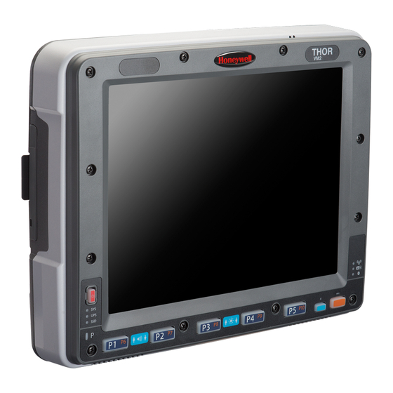
Back View - Thor VM2 Antenna Connectors SIM Card SD Card Access Access Panel Panel Dock Contact Pads Provision for Laptop Security Cable Provision for Padlock Quick Release Handle Thor VM2 with with Microsoft Windows Embedded CE 6.0 User Guide... -
Page 29: Access Panels - Thor Vm2
Access Panel Door is labeled with Front View - Dock Standard Dock Dock Contact Pads Enhanced Dock The Enhanced Dock has a foam surround around the dock contact pad. Dock Contact Pads Foam Surround Thor VM2 with with Microsoft Windows Embedded CE 6.0 User Guide... -
Page 30: Back View - Dock
COM2 port on the dock. If a screen blanking box is not connected via the power cable, the COM1 port on the dock is available for a serial device Thor VM2 with with Microsoft Windows Embedded CE 6.0 User Guide... -
Page 31: Top View - Enhanced Dock
3. Press the Blue key to exit Blue mode. Refer to the Screen Control panel for the current display brightness level. Screen Blanking The Thor VM2 can be configured to blank (blackout) the display while the vehicle is in motion. Refer to the Screen Control panel for information. -
Page 32: Keypad Backlight
Power Up If a USB drive, such as a thumb drive is attached to the Thor VM2, the device attempt to boot from the USB drive and cannot. Remove the USB drive and power up the Thor VM2 again. -
Page 33: Rebooting The Thor Vm2
• Use the P1 + P5 + Orange key press sequence to reboot the Thor VM2. The keys must be pressed in sequence; they do not need to be held down simultaneously. Thor VM2 with with Microsoft Windows Embedded CE 6.0 User Guide... -
Page 34: Tapping The Touch Screen With A Stylus
Clearing Persistent Storage / Reset to Default Settings Use the Registry control panel Load Factory Defaults button to set the Thor VM2 regis- try back to factory defaults. No other clearing is available or necessary. Tapping the Touch Screen with a Stylus Note: Always use the point of the stylus for tapping or making strokes on the touch screen. -
Page 35: Setup Terminal Emulation Parameters
Note: The instructions below are for Honeywell RFTerm. If a different terminal emulation software is installed on your Thor VM2 refer to the documentation for that software. Before you make a host connection, you will, at a minimum, need to know: •... -
Page 36: Cleaning The Touch Screen
Note: These instructions are for components made of glass. If there is a removable protective film sheet on the display, remove the film sheet before cleaning the screen. Keep rough or sharp objects away from the Thor VM2 touch screen and, if installed, the bar code reader scanning aperture. -
Page 37: Chapter 3 - Hardware Overview
CHAPTER HARDWARE OVERVIEW System Hardware 802.11a/b/g Wireless Client The Thor VM2 has an 802.11a/b/g network card that supports diversity with two inter- nal or external antennas. Power management for the network card is configured with Summit Client Utility. Central Processing Unit The CPU is a 1.6 GHz Intel Atom processor. -
Page 38: System Memory
Card Slots CompactFlash (CF) Slot The CF ATA slot is not hot swappable. The Thor VM2 must be powered down to insert or remove an ATA card. Since the operating system is stored on the CF ATA card, the Thor VM2 cannot operate without the ATA card. -
Page 39: Wwan
Universal Input Power Supply can be used to convert AC wall power to an appropri- ate DC level. AC to DC power input for the Thor VM2 is delivered to the dock via an optional external power supply and adapter cable. See External AC/DC Power Supply. - Page 40 Move the Thor VM2 to a different location to charge the UPS battery. When the Thor VM2 is operated in an environment where the UPS battery is not able to charge due to temperature extremes, the Thor VM2 should be removed to a location within the safe charging temperature range during off hours.
- Page 41 Battery. Reinstall the Thor VM2 in the dock and power on. Charging and Power Management • Charging does not occur when the Thor VM2 is in ignition mode and the ignition is inactive. • Charging of the UPS battery continues when the Thor VM2 is in power management (user idle, system idle or suspend modes).
-
Page 42: Backup Battery
On (D0), Backlight Off (D1), Display Off (D2) and Suspend (D3). On Mode (D0) When the Thor VM2 is attached to either vehicle power or an external power supply or is operating from the UPS battery and the power button is pressed, the Thor VM2 is in the On mode. - Page 43 By default power is turned off to the USB port when the Thor VM2 is in Suspend. The Thor VM2 can be configured to provide power to the USB port in Suspend using the Options control panel.
- Page 44 User Primary Events A User Primary Event transitions the Thor VM2 to D0 (On) mode. When no user event happens for the specified time period, the Thor VM2 transitions to D1 (User Idle), then D2 (System Idle) and then D3 (Suspend). Timeout periods are set via the Schemes tab in the Power control panel.
-
Page 45: Power Controls
If the Thor VM2 is On, pressing the power button places the unit in Suspend. Power Configuration Mode The Power Configuration Mode control panel is used to select desired power configura- tion behavior. Thor VM2 with with Microsoft Windows Embedded CE 6.0 User Guide... - Page 46 Auto-On Control Wiring Diagram. AC/DC The Thor VM2 is designed to power on whenever external power is attached. Due to the presence of external power, longer default power management timeouts are used. Ignition Control The Thor VM2 is configured to power on when the vehicle ignition is switched on. When the vehicle ignition is on, longer default power management timeouts are used.
-
Page 47: External Connectors
Power the Thor VM2 off before attaching a cable to any port (serial, USB, Audio/CAN, etc.). The external I/O connectors for the Thor VM2 are located on the right side of the dock (when viewed from the back). Power Supply Connector is on the left side of the dock (when viewed from the back). -
Page 48: Usb Connector(S)
An Ethernet port is located on the top of the Enhanced Dock. Lift the cover to access the Ethernet port. Note: A BIOS and operating system upgrade is necessary to support the Ethernet port. See Thor VM2 and Enhanced Dock Support for information. Thor VM2 with with Microsoft Windows Embedded CE 6.0 User Guide... -
Page 49: Canbus / Audio Connector
Dock for details. Power Supply Connector for connector pin- Standard Dock Enhanced Dock out detail. See Connect Power for more infor- mation on connecting power to the Thor VM2. Thor VM2 with with Microsoft Windows Embedded CE 6.0 User Guide... -
Page 50: Antenna Connections
VM2. The internal antennas are not user accessible. External 802.11 Antenna An external whip antenna can be connected to the Wi-Fi antenna connections on the back of the Thor VM2 for the 802.11 radio. Two external antennas are used for radio diversity. Install External Antenna for instructions. -
Page 51: Keyboard Options
Power control panel. • The integrated keypad backlight can be disabled via the Misc tab of the Options control panel. Keypad LEDs Keyboard LEDs for details. Thor VM2 with with Microsoft Windows Embedded CE 6.0 User Guide... -
Page 52: Usb Keyboards
Ctrl Enter The Thor VM2 uses an optional rugged QWERTY 95 key keyboard, designed for ease of use with the Windows operating system. The USB keyboard connects directly to the D9 USB connector (Standard Dock) or USB1 connector (Enhanced Dock). - Page 53 Since the keyboard is a USB device, by default the external keyboard backlight is turned off when the Thor VM2 enters Suspend. This behavior can be changed by enabling USB power in Suspend on the Misc tab of the Options control panel.
-
Page 54: Ps/2 Keyboards
PS/2 Keyboards Legacy PS/2 keyboards can be used with the Thor VM2 via a USB to PS/2 adapter cable. PS/2 keyboards are available in 60-key and 95-key versions and were used with the VX6, VX7, Thor VX8 or Thor VX9. - Page 55 However these keys send distinctly different scan codes when the keys are pressed. The default codes for the Thor VM2 number keys cor- respond to the numeric keypad on standard keyboards. In order to duplicate the codes sent when the alphanumeric key is pressed, the hidden keystroke must be used.
- Page 56 F4 and F5 keys are not used as the display brightness is adjusted via the buttons on the Thor VM2. • The 2 functions of the F6 and F7 keys are not used as the Thor VM2 has TFT LCD screen with no provision for contrast adjustments. • The 2 functions of the F8 and F9 keys are not used as the sound volume on the Thor VM2 is controlled with the Sound icon in the Microsoft Windows System Tray.
-
Page 57: Usb Keyboard / Mouse
BkSp to enter the Insert (Ins) mode. USB Keyboard / Mouse A standard USB keyboard or mouse can be attached to the Thor VM2 using the appro- priate adapter cable. The Y cable attaches to the Thor VM2 and provides a USB connector. Please refer to documentation provided with the USB keyboard or mouse for more information on their operation. -
Page 58: Led Functions
CPU for 30 sec. Green blinking slowly CPU temperature less External power not present than -20ºC, Need to (1/2 sec. on, 1 1/2 sec. off) move unit to warmer environment Thor VM2 with with Microsoft Windows Embedded CE 6.0 User Guide... - Page 59 Neither charging or discharging Unit is off or is in Suspend SSD (Solid State Drive) LED LED Behavior Status Flashing Green SSD read or write activity No SSD read or write activity Thor VM2 with with Microsoft Windows Embedded CE 6.0 User Guide...
-
Page 60: Connection Leds
It blinks once for a very short time every 2 seconds when paired and connected. It blinks every second when in discovery. The LED is off when the Bluetooth client is off. Thor VM2 with with Microsoft Windows Embedded CE 6.0 User Guide... -
Page 61: Keyboard Leds
Default mode. Refer to application developer for LED behavior details. The LED behavior is controlled by the NLedDriverSetDevice API. Please refer to the CE API Programming Guide for API details. Thor VM2 with with Microsoft Windows Embedded CE 6.0 User Guide... -
Page 62: Display
Technical Assistance for availability. Note: If the touch screen is disabled or loses calibration on a Thor VM2, you must use a USB mouse or keyboard attached to the Thor VM2 to access the control panel to re-enable or recalibrate the touch screen unless a programmable key has been assigned to that function. - Page 63 Thor VM2 with with Microsoft Windows Embedded CE 6.0 User Guide...
- Page 64 Thor VM2 with with Microsoft Windows Embedded CE 6.0 User Guide...
-
Page 65: Chapter 4 - Vehicle Mounting And Accessory Installation
For an AC powered application: Use an AC/DC power supply and the VMXD off- vehicle enhanced dock. The Thor VM2 is designed to be mounted to a dock in a vehicle with either a RAM mount or U Bracket system. A power cable is provided with the Thor VM2 dock. An optional 21 key numeric or 95 key laptop-style USB keyboard and keyboard mounts are available. -
Page 66: Prepare For Vehicle Mounting
Quick Start The following list outlines, in a general way, the process to follow when mounting the Thor VM2 in a vehicle. Refer to the following sections in this document for more details. Install RAM Mount Install U Bracket Mount to the vehicle. -
Page 67: Maintenance - Vehicle Mounted Devices
1. Locate the notch on the upper rear of the Thor VM2. 2. Slide this notch over the top lip of the dock. Slide the Thor VM2 from side to side on the dock to make sure it fully engages on the lip of the dock. If the Thor VM2 cannot be slid side to side, the lip is engaged. - Page 68 • If the Thor VM2 is off and power is connected to the dock, the Thor VM2 may boot when placed in the dock. The behavior depends on the Power Configuration Mode selected. See Ignition Control Mode Auto-On Mode. •...
-
Page 69: Dock I/O Pin Cover
Dock I/O Pin Cover. The dock contains a tethered I/O Pin Cover to protect the I/O pins on the dock when a Thor VM2 is not mounted in the dock. • When the Thor VM2 is not installed in the dock, use the I/O Pin Cover to protect the pins on the dock as shown. -
Page 70: Install Ram Mount
In addition to the kits below, individual RAM mounting components are also available. Mounting Kits without Keyboards Each mounting kit contains: RAM Ball (Size D) for back of Thor VM2 dock with hardware (screws and washers) to attach RAM ball to dock... - Page 71 Hardware (cone washers and nuts) to attach Ball to Plate Mounting Kits with Integrated Keyboard Mounting Additionally, the kits for the Thor VM2 with an integrated 95 key keyboard mount include: Thor VM2 Keyboard Mounting Bracket RAM Ball (Size C) with hardware (nuts) to attach RAM ball...
-
Page 72: Procedure - Ram Mount Assembly
Equipment Needed: Sockets, screwdriver and a Torque wrench capable of measuring to 50 inch pounds (5.64±.56 N/m). Note: Torquing tool is not supplied by Honeywell. Tools needed to attach the RAM Clamp Mount to the vehicle are not supplied by Honeywell. - Page 73 1. Determine the position for mounting the RAM ball base. Be sure to position the RAM bracket to allow access to the switches and ports on the bottom of the Thor VM2. 2. Attach the RAM ball base to the vehicle mounting surface using three or four 1/4 bolts (not included) or equivalent fasteners.
- Page 74 2” (50.8 mm) thick. The clamp may be attached to a thicker beam by substituting longer bolts (not included). Be sure to position the RAM clamp mount to allow access to the switches and ports on the bottom of the Thor VM2. Bolts...
- Page 75 1. Determine the position for mounting the RAM ball plate. Be sure to position the RAM plate to allow access to the switches and ports on the bottom of the Thor VM2. 2. Attach the RAM ball plate to the vehicle mounting surface using four 1/4 bolts (not included) or equivalent fasteners.
- Page 76 3. If using the external keyboard mount, position the Keyboard Bracket and the Size D RAM ball on the rear of the Thor VM2 dock, aligning the holes on the back of the Thor VM2 dock with the holes on the bracket and the RAM ball base.
- Page 77 1. Slip the Size D RAM arm over the ball on the vehicle RAM mount (RAM Ball mount shown). 2. Insert the ball on the dock into the RAM arm and tighten the knob on the RAM arm using the supplied RAM wrench. Thor VM2 with with Microsoft Windows Embedded CE 6.0 User Guide...
- Page 78 Step 4 – Place the Thor VM2 into the Dock If the Thor VM2 is not already mounted to the dock, Place Thor VM2 in the Dock If the optional external keyboard is not used, the mounting process is complete.
- Page 79 Step 5 – Attach Alphanumeric Keyboard to Mounting Plate (Optional) Note: This step is only for a Thor VM2 with the optional external keyboard. If using the optional integrated keyboard mount, attach the keyboard to keyboard mounting plate, using four #8 screws, flat washers and lock washers.
- Page 80 Note: This step is only for a Thor VM2 with the optional external keyboard. 1. Slip the Size C RAM arm over the ball on the Thor VM2 Keyboard Bracket. 2. Slip the ball on the Keyboard Mounting Plate into the other end of the Size C RAM arm.
- Page 81 3. Slip the RAM arm over the accessory RAM ball. 4. Slip the RAM ball on the keyboard into the RAM arm. 5. Tighten the knob on the RAM arm while adjusting to the desired angle. Thor VM2 with with Microsoft Windows Embedded CE 6.0 User Guide...
- Page 82 3. Slip the RAM arm over the accessory RAM ball. 4. Slip the RAM ball on the scanner holder into the RAM arm. 5. Tighten the knob on the RAM arm while adjusting to the desired angle. Thor VM2 with with Microsoft Windows Embedded CE 6.0 User Guide...
-
Page 83: Install U Bracket Mount
With a U Bracket included for new vehicle installations • Without a U Bracket for installing the Thor VM2 in place of a previous Honeywell vehicle mounted computer, such as a VX6 or VX7. U Bracket (only necessary for new installations) -
Page 84: Procedure - U Bracket Assembly
The adapter bracket can be mounted in a high or low position, depending on viewing position, as shown below. Additionally, the slotted U bracket allows the Thor VM2 to be mounted vertically or tilted forward or backward for best viewing angle. - Page 85 4. 1.02 in / 25.9 mm 5. 3.38 in / 85.85 mm 6. Vehicle Mount Footprint 7. 0.406 in / 10.312 mm 8. 0.88 in / 22.3 mm 9. 1.25 in / 31.75 mm Thor VM2 with with Microsoft Windows Embedded CE 6.0 User Guide...
- Page 86 Step 2 - Remove RAM Ball If the Thor VM2 dock has a RAM ball attached, the RAM ball must be removed from the dock to use the U Bracket mount. Remove the RAM ball. The hardware used to attach the RAM ball to the dock is not reused for the U bracket mount.
-
Page 87: Connect Cables
Connect Cables There are many cables available for the Thor VM2 including power cables, and data/ communication cables. Strain Relief Cable Clamps Equipment Required: Phillips screwdriver (not supplied by Honeywell) There are five strain relief cable clamps secured to the Standard Dock. -
Page 88: Connect Power
- For applications where a Thor VM2 (with a VMXD Enhanced Dock) replaces a previously installed Thor VX8 or Thor VX9. When using the Thor VM2 with AC power, use the VMXD Enhanced Dock for Off-Vehi- cle Use and: •... - Page 89 The power cable is less flexible in low temperature environments. Avoid sharp bends. Caution: Regularly inspect power cable for damage, especially in low temperature environments. Contact Technical Assistance replacement cable options. Thor VM2 with with Microsoft Windows Embedded CE 6.0 User Guide...
- Page 90 12VDC. • For 24VDC input, use the 6A fuse from the kit or a slow blow fuse that has a DC voltage rating greater than 24VDC. Thor VM2 with with Microsoft Windows Embedded CE 6.0 User Guide...
- Page 91 (ESD) protection. Vehicle 10-60VDC Direct Power Connection 1. The Thor VM2 must not be mounted in the dock. The power switch on the dock must be turned Off. The power cable must be UNPLUGGED from the dock. 2. While observing the...
- Page 92 Thor VM2 ignition signal wire can be connected (less than 1mA over input volt- age range) to the switched circuit to allow the Thor VM2 to power on when the vehicle is switched on. When the vehicle is switched off, more aggressive power management set- tings are enabled to preserve the vehicle battery charge.
- Page 93 • For 12VDC input, use the 10A fuse from the kit or a slow blow fuse that has a DC voltage rating greater than 12VDC. Thor VM2 with with Microsoft Windows Embedded CE 6.0 User Guide...
- Page 94 For 48VDC input, use the 3A fuse from the kit or a slow blow fuse that has a DC voltage rating greater than 48VDC. Note: For North America, a UL Listed fuse is to be used. Thor VM2 with with Microsoft Windows Embedded CE 6.0 User Guide...
- Page 95 Black wire must be connected to battery negative. If there is a black wire and a black/ white wire, twist them together and connect to battery negative. • Green wire is connected to the vehicle chassis ground, which can also be battery negative. Thor VM2 with with Microsoft Windows Embedded CE 6.0 User Guide...
- Page 96 For 48VDC input, use the 3A fuse from the kit or a slow blow fuse that has a DC voltage rating greater than 48VDC. Note: For North America, a UL Listed fuse is to be used. Thor VM2 with with Microsoft Windows Embedded CE 6.0 User Guide...
- Page 97 Black wire must be connected to battery negative. If there is a black wire and a black/ white wire, twist them together and connect to battery negative. • Green wire is connected to the vehicle chassis ground, which can also be battery negative. Thor VM2 with with Microsoft Windows Embedded CE 6.0 User Guide...
- Page 98 For 48VDC input, use the 3A fuse from the kit or a slow blow fuse that has a DC voltage rating greater than 48VDC. Note: For North America, a UL Listed fuse is to be used. Thor VM2 with with Microsoft Windows Embedded CE 6.0 User Guide...
- Page 99 The power supply should be mounted in a dry location within the vehicle or placed in a suitable protective enclosure. Caution: Use caution when routing the power cable. See Power Cable Cautions. Thor VM2 with with Microsoft Windows Embedded CE 6.0 User Guide...
- Page 100 Wiring Diagram, before beginning power cable install. 2. The Thor VM2 must not be mounted in the dock. The power switch on the dock must be turned Off. The power cable must be UNPLUGGED from the dock. Thor VM2 with with Microsoft Windows Embedded CE 6.0 User Guide...
- Page 101 3. Route the cable from the Thor VM2 to the DC/DC power supply. Route the power cable the shortest way possible. The cable is rated for a maximum temperature of 105°C (221°F). When routing this cable, it should be protected from physical damage and from surfaces that might exceed this temperature.
- Page 102 17. Connect the watertight connector end of the power cable to the Thor VM2 dock power connector by aligning the connector pins to the power connector; push down on the watertight connector and twist it to fasten securely.
- Page 103 For all voltages, use the 3A fuse from the kit or a slow blow fuse that has a DC voltage rating greater than the vehicle input voltage. Note: For North America, a UL Listed fuse is to be used. Thor VM2 with with Microsoft Windows Embedded CE 6.0 User Guide...
- Page 104 The power supply should be mounted in a dry location within the vehicle or placed in a suitable protective enclosure. Caution: Use caution when routing the power cable. See Power Cable Cautions. Thor VM2 with with Microsoft Windows Embedded CE 6.0 User Guide...
- Page 105 Wiring Diagram, before beginning power cable install. 2. The Thor VM2 must not be mounted in the dock. The power switch on the dock must be turned Off. The power cable must be UNPLUGGED from the dock. Thor VM2 with with Microsoft Windows Embedded CE 6.0 User Guide...
- Page 106 3. Route the cable from the Thor VM2 to the DC/DC power supply. Route the power cable the shortest way possible. The cable is rated for a maximum temperature of 105°C (221°F). When routing this cable, it should be protected from physical damage and from surfaces that might exceed this temperature.
- Page 107 16. Connect the watertight connector end of the power cable to the Thor VM2 dock power connector by aligning the connector pins to the power connector; push down on the watertight connector and twist it to fasten securely.
- Page 108 For all voltages, use the 3A fuse from the kit or a slow blow fuse that has a DC voltage rating greater than the vehicle input voltage. Note: For North America, a UL Listed fuse is to be used. Thor VM2 with with Microsoft Windows Embedded CE 6.0 User Guide...
- Page 109 Enhanced Dock only. An adapter cable is available to attach the Thor VM2 to a vehicle previously equipped with a VX6/VX7 DC power cable. The adapter cable has a 5-pin connector to match with the VX6/VX7 power supply cable on one end and a 6-pin connector to match to the Thor VM2 on the other end.
- Page 110 VM2 on the other end. The cable also has bare wires for ground and ignition sense con- nection plus a D9 cable to connect to a COM port on the Thor VM2 dock to provide a screen blanking signal. This section assumes the VX8/VX9 power cable is properly con- nected to vehicle power.
- Page 111 7. Connect the watertight connector end of the power cable to the Thor VM2 dock power connector by aligning the connector pins to the power connector; push down on the watertight connector and twist it to fasten securely.
- Page 112 CV61 DC power cable. The adapter cable has a 5-pin connector to match with the VV61 power supply cable on one end and a 6-pin connector to match to the Thor VM2 on the other end. This section assumes the CV61 power cable is properly connected to vehicle power.
- Page 113 Honeywell Screen Blanking Box Cable An optional Honeywell Screen Blanking Box Cable is available. Thor VM2 with with Microsoft Windows Embedded CE 6.0 User Guide...
- Page 114 Connected to Screen Blanking Box, switched Gray (see note) side Note: Wire colors only apply to optional Honeywell Screen Blanking Box Cable, VM1080CABLE. Wire colors may vary in a user-supplied cable. The optional Honeywell Screen Blanking Box Cable, VM1080CABLE, is installed as fol-...
- Page 115 To pin 7 of COM1 or COM2 To pin 8 of COM1 or COM2 Note: The black and gray wire colors in the illustration only apply to the optional Honeywell Screen Blanking Box Cable, VM1080CABLE. The wire colors may be different in a user- supplied cable.
- Page 116 To pins 7 and 8 of COM1 or COM2 port on dock Pins 7 and 8 must be connected as shown in the illustration above. No other pins are to be connected. Thor VM2 with with Microsoft Windows Embedded CE 6.0 User Guide...
- Page 117 Determine the type of power supply used with the previous Thor VX8 or Thor VX9 instal- lation: • DC/DC Power Supply with Screws on Top of Lid • DC/DC Power Supply with Screws on Side of Lid Thor VM2 with with Microsoft Windows Embedded CE 6.0 User Guide...
- Page 118 Supplied Power Cable Power (Shielding to be trimmed) Supply Caution: For battery powered vehicles: • + is connected to battery positive. • - must be connected to battery negative. Thor VM2 with with Microsoft Windows Embedded CE 6.0 User Guide...
- Page 119 Caution: For internal combustion engine powered vehicles: • + is connected to battery positive. • - is connected to battery negative. • is connected to the vehicle chassis ground, which can also be battery negative. Thor VM2 with with Microsoft Windows Embedded CE 6.0 User Guide...
- Page 120 Caution: For battery powered vehicles: • + is connected to battery positive. • - must be connected to battery negative. • GND must be connected to the vehicle chassis ground. Thor VM2 with with Microsoft Windows Embedded CE 6.0 User Guide...
- Page 121 • + is connected to battery positive. • - is connected to battery negative. • GND is connected to the vehicle chassis ground, which can also be battery negative. Thor VM2 with with Microsoft Windows Embedded CE 6.0 User Guide...
- Page 122 5. Press the Power Switch on the back of the Thor VM2 dock. 6. Press the Power Button on the front of the Thor VM2 to turn on the Thor VM2. Thor VM2 with with Microsoft Windows Embedded CE 6.0 User Guide...
- Page 123 Table Stand When the Thor VM2 is used in an office environment, it can be mounted in a table stand. To use the table stand: 1. Attach the RAM ball to the RAM Metal Table Stand with the supplied screws and nuts.
-
Page 124: Connect Usb Keyboard
1. Seat the keyboard cable connector over the USB or USB1 connector on the dock. 2. Tighten the thumbscrews in a clockwise direction. Do not over tighten. 3. Secure the cable to the Thor VM2 with Strain Relief Cable Clamps. Thor VM2 with with Microsoft Windows Embedded CE 6.0 User Guide... -
Page 125: Connect Ps/2 Keyboard
A legacy PS/2 keyboard (used with VX6, VX7, Thor VX8 or Thor VX9), available in either 60-key or 95-key versions can be used with the Thor VM2 via a PS/2 to USB adapter cable. 1. Seat the male connector of the cable over the USB connector on the Thor VM2 dock. - Page 126 5. Secure the cable to the Thor VM2 with Strain Relief Cable Clamps. The strain relief must capture the keyboard cable. Thor VM2 with with Microsoft Windows Embedded CE 6.0 User Guide...
-
Page 127: Connect Usb Host
3. The USB-host connectors provide a connector for a USB device such as a USB thumb drive. 4. Secure the cables to the Thor VM2 with Strain Relief Cable Clamps. Thor VM2 with with Microsoft Windows Embedded CE 6.0 User Guide... -
Page 128: Connect Usb Client
2. Tighten the thumbscrews in a clockwise direction. Do not over tighten. 3. The USB client connector provides a client connection, such as for ActiveSync to a 4. Secure the cables to the Thor VM2 with Strain Relief Cable Clamps. Thor VM2 with with Microsoft Windows Embedded CE 6.0 User Guide... -
Page 129: Connect Serial Device
1. The scanner cable is attached to either the COM1 or COM2 port on the dock. 2. Connect the serial cable for the scanner as directed above. 3. When the Thor VM2 is powered on, it provides power to the serial scanner. 4. Configure the Data Collection (DC) Wedge to manipulate scanned data as desired. - Page 130 Tuck the cable under the belt, but leave a small loop where it goes under the belt. • Do not wear the cable on the front of your body. It may get in your way or get caught on protruding objects. Thor VM2 with with Microsoft Windows Embedded CE 6.0 User Guide...
-
Page 131: Connect Canbus Cable
Connect CANbus Cable The CANbus/Audio connector supports a headset adapter cable or a CANbus Y cable. The Thor VM2 does not support connecting audio and CANbus simultaneously. CANbus / Audio Connector for connector pinouts. 1. Seat the D15 cable end connector firmly over the CANbus/Audio Connector on the dock. -
Page 132: Install Remote Antenna
The Vehicle Remote Mount Antenna cannot be used by devices with an internal antenna. Components and Mounting Diagram Washer Washer Bracket To antenna Antenna To antenna Bracket To antenna connector on computer Thor VM2 with with Microsoft Windows Embedded CE 6.0 User Guide... - Page 133 6. Connect the cable to the antenna connector (Wi-Fi Main or Wi-Fi Aux) on the Thor VM2. If only one antenna is used, be sure to connect it to the Wi-Fi Main connector. 7. Repeat the steps above for the second 802.11 antenna. Thor VM2 with with Microsoft Windows Embedded CE 6.0 User Guide...
- Page 134 6. Use cable ties to secure the coaxial cable to the vehicle as necessary. Make sure the cable is routed so it is not damaged by any moving parts of the vehicle. Thor VM2 with with Microsoft Windows Embedded CE 6.0 User Guide...
- Page 135 5. Use cable ties to secure the coaxial cable to the vehicle as necessary. Make sure the cable is routed so it is not damaged by any moving parts of the vehicle. Thor VM2 with with Microsoft Windows Embedded CE 6.0 User Guide...
-
Page 136: Apply Touch Screen Protective Film
Apply Touch Screen Protective Film The optional Thor VM2 touch screen protective film is shipped in packs of 10. The pro- tective film is flexible and treated with an anti-glare coating on the outer surface. The protective film is slightly larger than... -
Page 137: Removal
2. Lift up on the edge of the protective film so it does not slide between the touch screen and display housing when the protective film is slid back to the center. 3. Repeat until all edges are free and remove the protective film. Thor VM2 with with Microsoft Windows Embedded CE 6.0 User Guide... -
Page 138: Disconnect Ups Battery
M3 screws and then remove the tethered access panel with the SIM label. This panel is on the right hand side when the Thor VM2 is face down with the top away from the user. 6. Locate the small push button located just below the SIM card installation slot. -
Page 139: Install Sd Card
M3 screws and then remove the tethered access panel with the SIM label. This panel is on the left hand side when the Thor VM2 is face down with the top away from the user. 6. Locate the SD card installation slot. - Page 140 19. Reattach the access panel, torquing the screws to 7.0 ± 0.5 inch pounds. 20. Reinstall the Thor VM2 in the dock. 21. Restart the Thor VM2. Thor VM2 with with Microsoft Windows Embedded CE 6.0 User Guide...
-
Page 141: Install Sim Card
6. Locate the SIM card installation slot, as highlighted to the right. 7. Slide the SIM card into the slot. Note: The entire SIM slot is not visible due to the design of the Thor VM2 case. However, the entire slot is shown below to help with installation. - Page 142 11. If removed, reinstall the Thor VM2 in the dock. 12. Resume the Thor VM2 from suspend. 13. Restart the Thor VM2 (Start > Settings > Control Panel > Registry and tap the Restart button). Thor VM2 with with Microsoft Windows Embedded CE 6.0 User Guide...
-
Page 143: Replace Front Panel
Power button. 3. Remove the Thor VM2 from the dock. Disconnect UPS Battery. 5. Loosen the twelve (12) captive M3 screws holding the front panel. Use a #2 Phillips bit. Thor VM2 with with Microsoft Windows Embedded CE 6.0 User Guide... - Page 144 #2 Phillips bit and torque the screws to 6-7 inch pounds. 11. Reinstall the Thor VM2 in the dock. 12. When the Thor VM2 is placed in the powered dock, the UPS battery automatically reconnects. 13. Restart the Thor VM2.
-
Page 145: Chapter 5 - Software
Thor VM2 and its Windows environment. General Windows CE Keyboard Shortcuts Use the keyboard shortcuts in the chart below to navigate with the Thor VM2 keyboard. These are standard keyboard shortcuts for Windows CE applications. Press these keys …... -
Page 146: Save Changes To The Registry
UPS charge reaches a critically low level and external power is not available. The registry save process takes 0 – 3 seconds. If nothing has been changed, nothing is saved (e.g., 0 seconds). Thor VM2 with with Microsoft Windows Embedded CE 6.0 User Guide... -
Page 147: Software Load
• Network and Device Drivers • Bluetooth Note: Please contact Honeywell Technical Assistance for software updates and CAB files as they are released by Honeywell. Software Applications The following applications are included: •... -
Page 148: Rfterm (Optional)
Only installed on a Bluetooth equipped Thor VM2. The System Administrator can Dis- cover and Pair targeted Bluetooth devices for each Thor VM2. The System Administrator can enable / disable Bluetooth settings and assign a Computer Friendly name for each Thor VM2. - Page 149 Order is used to force a sequence of events. Order=0 is first, and Order=99 is last. Order must be greater than 4 for the Thor VM2. Two items which have the same order will be installed in the same pass, but not in a predictable sequence.
-
Page 150: Launch.exe And Persistent Storage
Note: Files in the Startup folder are executed, but only from System > Startup. They are not copied to another folder. REGEDIT.EXE Registry Editor – Use caution when editing the Registry. Make a backup copy of the reg- istry before changes are made. Thor VM2 with with Microsoft Windows Embedded CE 6.0 User Guide... -
Page 151: Regload.exe
Note: For general use instruction, please refer to commercially available Windows CE user’s guides or the Windows on-line Help application installed in the mobile device. The Thor VM2 Desktop appearance is similar to that of a desktop PC running a Windows operating system. -
Page 152: Desktop Icons
Favorites, Documents, Settings, Help, and Run. Desktop Icons At a minimum, the desktop displays icons for My Device, Internet Explorer and the Recycle Bin. Following are a few of the other icons that may be on the Thor VM2 Desk- top. Contact Technical Assistance about the latest updates and upgrades for your oper- ating system. -
Page 153: My Device Folders
The enabler for Wavelink Avalanche is loaded on the Thor VM2 but not installed. When the enabler is installed the Avalanche icon is displayed on the desktop. -
Page 154: Internet Explorer
Enabler update Related Manual: Using Wavelink Avalanche. The Thor VM2 has the Avalanche Enabler installation files loaded, but not installed, on the mobile device when it is shipped. The installation files are located in the System folder on CE devices. The installation application must be run manually the first time Avalanche is used. -
Page 155: Communication
Start > Programs > Communication Connect ActiveSync is preloaded on the Thor VM2. Tap the Connect to initiate an ActiveSync con- nection. Note: By default, ActiveSync is configured to connect automatically when the USB cable is connected to a PC. -
Page 156: Command Prompt
There are a few changes in the Windows CE version of Internet Explorer as it relates to the general desktop Windows PC Internet Explorer options. Tap the “?” button to access Internet Explorer Help. Thor VM2 with with Microsoft Windows Embedded CE 6.0 User Guide... -
Page 157: Media Player
There are few changes in the Windows E version of Remote Desktop as it relates to the general desktop Windows PC Microsoft Remote Desktop options. If installed, Remote Desktop on the Thor VM2 can be accessed by Start > Programs > Remote Desktop. -
Page 158: Settings
Clicking the Taskbar option on the Settings menu displays the General and Advanced Taskbar tabs. General Factory Default Settings Always on Top Enabled Auto hide Disabled Show Clock Enabled Thor VM2 with with Microsoft Windows Embedded CE 6.0 User Guide... -
Page 159: Advanced
Refer to Start > Help for an explanation of standard Windows E taskbar icons. Following are a few of the Thor VM2 taskbar icons that may appear in the Taskbar. These icons are in addition to the Windows E taskbar icons. -
Page 160: Thor Vm2 Os Upgrade
Maintain an uninterrupted AC/DC power source to the Thor VM2 throughout this process. • The CF card with the OS and systems files must be present for the Thor VM2 to boot. Removal or installation of SD or CF cards should be performed on a clean, well-lit surface. -
Page 161: Procedure
Always perform OS updates when the Thor VM2 has a dependable external power source connected to the Thor VM2. Procedure 1. Verify a dependable power source is applied to the Thor VM2 and will stay connected during the upgrade procedure. 2. Warmboot the Thor VM2 before beginning the update process. -
Page 162: Accessing The Bios Setup
By default, the first device in the boot order is USB Hard Drive. The second device is the Windows CE Image. If a USB drive, such as a thumb drive, is attached to the Thor VM2 the Thor VM2 attempts to boot from the USB drive: •... -
Page 163: Control Panel
Control Panel Start > Settings > Control Panel or My Device > Control Panel Tap the ? button for Help when changing Thor VM2 Control Panel options. Option Function About Software, hardware, versions and network IP. No user intervention allowed. - Page 164 Enable / disable volume and sounds. Set volume parameters and assign sound WAV files to events. Wi-Fi Set the parameters for a Summit Client Utility (if this icon is not present, see SCU). Thor VM2 with with Microsoft Windows Embedded CE 6.0 User Guide...
-
Page 165: About
Thor VM2. The Image line displays the revision of the system soft- ware installed. Refer to the last three digits to determine the revision level. - Page 166 64K byte text box lim- itation. Network IP MAC Address The Network IP tab displays the MAC address of the network card(s) such as the Sum- mit WLAN radio and the Bluetooth module. Thor VM2 with with Microsoft Windows Embedded CE 6.0 User Guide...
-
Page 167: Accessibility
Accessibility Start > Settings > Control Panel > Accessibility Customize the way the Thor VM2 keyboard, sound, display, mouse, automatic reset and notification sounds function. There are a few changes from general Windows desktop Accessibility options. Contents Keyboard Sticky Keys - Disabled (cannot be enabled). -
Page 168: Administration
AppLock program is installed as part of the default software load and is configured with the Administration control panel. Configuration parameters are specified by the AppLock Administrator for the Thor VM2 end-user. AppLock is password protected by the Administrator. End-user mode locks the end-user into the configured application or applications. The end user can still reboot the mobile device and respond to dialog boxes. - Page 169 Devices with the AppLock feature are shipped to boot in Administration mode with no default password, thus when the Thor VM2 is first booted, the user has full access to the device and no password prompt is displayed. After the administrator specifies the appli- cations to lock, a password is assigned and the device is rebooted or the hotkey is pressed, the device switches to end-user mode.
- Page 170 In addition to these configuration options, the administrator can view and manage the status logs of AppLock sessions. Administrator default values for this device: Administrator Hotkey Shift+Ctrl+A Note: You must use an external keyboard with the Thor VM2 to enter the Administrator Hotkey. Password none Application path and name none...
- Page 171 AppLock will wait until the correct password is entered. Forgotten password? AppLock Help End-User Switching Technique Note: The touch screen must be enabled. Thor VM2 with with Microsoft Windows Embedded CE 6.0 User Guide...
- Page 172 A check mark indicates applications currently active or available for Launching by the user. When Keyboard is selected, the Thor VM2 default input method (Input Panel, Tran- scriber, or custom input method) is activated. The check to the left of the application name indicates that the application is active.
- Page 173 Note that the system administrator may have assigned a different key sequence to use when switching applications. Note: You must use an external keyboard with the 12-key version of the Thor VM2 to use the Hotkey. If an external keyboard is not attached, use the Switchpad to switch between applications.
- Page 174 Application Launch Options Tap the Launch... button to access the application launch options. This panel displays the Launch options panel for the Filename selected on the Administration panel. Thor VM2 with with Microsoft Windows Embedded CE 6.0 User Guide...
- Page 175 Note: Launch order is determined by the Order specified in the Application tab. The Order value does not have to be sequential. Auto Re-Launch Auto Re-Launch Default is Enabled. Thor VM2 with with Microsoft Windows Embedded CE 6.0 User Guide...
- Page 176 2) never launched, and 3) not displayed on the Switchpad. Allow Close Default is Disabled. When enabled, the associated application can be closed by the end- user. Thor VM2 with with Microsoft Windows Embedded CE 6.0 User Guide...
- Page 177 This means that IEXPLORER.EXE should be specified in the Application text box and the Internet application should be entered in the command line. In this case, do not check the Internet checkbox. Security Thor VM2 with with Microsoft Windows Embedded CE 6.0 User Guide...
- Page 178 Application Launch Options panel are delays before AppLock attempts to start the specified application(s). The tim- eouts specified on this panel are delays after AppLock has attempted to launch the application. Thor VM2 with with Microsoft Windows Embedded CE 6.0 User Guide...
- Page 179 Move the cursor to the Filename text box and either type the logfile path or tap the Browse button (the … button). The standard Windows CE Browse dialog is displayed. After selecting the logfile from the Browse dialog, tap OK. Thor VM2 with with Microsoft Windows Embedded CE 6.0 User Guide...
- Page 180 If the configuration is valid for one application but not the other, the switch to end-user mode fails. AppLock stays in Administration mode and is stopped until the Administra- tor password is entered. The hotkey sequence needed is not allowed. What does this mean? Thor VM2 with with Microsoft Windows Embedded CE 6.0 User Guide...
- Page 181 When RFTerm is not installed on the mobile device, the RFTerm keys are not restricted from use. Can’t locate the password that has been set by the administrator? Contact Technical Assistance for password help. Thor VM2 with with Microsoft Windows Embedded CE 6.0 User Guide...
-
Page 182: Battery
50%, 25%. At a point below 25% the gas gauge icon will turn red indicating the battery is low. The battery gauge icon is enabled by default, but can be disabled on the Thor VM2 Battery control panel. The UPS LED turns red when there is approximately 2 minutes of run time remaining. -
Page 183: Bluetooth
Assistance for software upgrade information. • The EZPair bar code on the Thor VM2 cannot be used to connect the SR61 scanner. Follow this procedure: 1. Make sure the scanner is on and within range of the Thor VM2. 2. Tap the Discover button on the Bluetooth Devices tab. - Page 184 When Filtered Mode is enabled, the Thor VM2 can pair with one Bluetooth scanner and one Bluetooth printer. • When Filtered Mode is disabled, the Thor VM2 can pair with up to four Bluetooth devices • It is not necessary to disconnect a paired scanner and printer before a different scanner or printer is paired with the Thor VM2.
- Page 185 Tap Stop at any time to end the Discover and Query for Unique Identifier functions. Devices not paired are not shown after any reboot sequence. Note: When an active paired device enters Suspend Mode, is turned Off or leaves the Thor VM2 Bluetooth scanning range, the Bluetooth connection between the paired device and the Thor VM2 is lost.
- Page 186 Stop the connection between the Thor VM2 and the highlighted paired Bluetooth device. Delete Remove an unpaired device from the Bluetooth device list. The highlighted device name and identifier is removed from the Thor VM2 Bluetooth Devices panel after the user taps OK. Properties More information on the highlighted Bluetooth device.
- Page 187 This option is Enabled by default. request to pair A dialog box appears on the Thor VM2 screen notifying the user a Bluetooth device requests to pair with the Thor VM2. The requesting Bluetooth device does not need to have been Discovered by the Thor VM2 before the pairing request is received.
- Page 188 Logging This option is Disabled by default. When logging is enabled, the Thor VM2 creates bt_log.txt and stores it in the /System folder. Bluetooth activity logging is added to the text file as activity progresses. A bt_log_bak.txt file contains the data stored by bt_log.txt prior to reboot.
- Page 189 (example: return from out-of-range). The pairing table is cleared on boot. The status of Auto Reconnect on Boot is ignored and the option is automatically disabled (unchecked) and dimmed. About Thor VM2 with with Microsoft Windows Embedded CE 6.0 User Guide...
- Page 190 Bluetooth Devices Display - Before Discovering Devices Note: When Filtered Mode is enabled, only Bluetooth printers or Bluetooth scanners/imagers are recognized and displayed in the Bluetooth panel. All other Bluetooth devices are ignored. Thor VM2 with with Microsoft Windows Embedded CE 6.0 User Guide...
- Page 191 6. Tap Pair as Scanner to set up the Thor VM2 to receive scanner data. 7. Tap Pair as Printer to set up the Thor VM2 to send data to the printer. 8. Tap Serial Device (when Filtered mode is disabled) to set up the Thor VM2 to communicate with a Bluetooth serial device.
- Page 192 Thor VM2 is out of range of all paired Bluetooth device(s). Connection is inactive. Note: When an active paired device enters Suspend Mode, is turned Off or leaves the Thor VM2 Bluetooth scan range, the Bluetooth connection between the paired device and the Thor VM2 is lost.
- Page 193 LED flashes. See Bluetooth Beep and LED Indications. Note: After scanning the Thor VM2 Bluetooth label, if there is no beep and no LED flash from the Bluetooth device, the devices are currently paired. Thor VM2 without Label...
- Page 194 The devices are paired. The Bluetooth bar code reader responds with a series of beeps and LED flashes. Note: After scanning the Thor VM2 Bluetooth label, if there is no beep and no LED flash from the Bluetooth bar code reader, the devices are currently paired.
- Page 195 3. Tap and hold the stylus (or double-tap) on the Bluetooth printer ID until the right- mouse-click menu appears. 4. Select Pair as Printer to pair the Thor VM2 with the Bluetooth managed printer. The devices are paired. The Bluetooth managed printer may respond with a series of beeps or LED flashes.
-
Page 196: Certificates
Start > Settings > Control Panel > Certificates Manage digital certificates used for secure communication. Note: Digital certificates are date sensitive. If the date on the Thor VM2 is incorrect, wireless authentication will fail. The Certificates stores tab lists the certificates trusted by the Thor VM2 user. -
Page 197: Data Collection
Thor VM2 in a transparent manner. Note: When a HID enabled USB scanner is connected to the Thor VM2 the scanned data is transmitted to the active window as keystroke messages. The data bypasses the data collection wedge. - Page 198 13. If key output is disabled, a windows message is broadcast to notify listening applications that data is available. The manipulated data is ready to be read by applications. Thor VM2 with with Microsoft Windows Embedded CE 6.0 User Guide...
-
Page 199: Factory Default Settings
Main Start > Settings > Control Panel > Data Collection > Main tab The parameters shown on these panels are only those that apply to the specific mobile device. Thor VM2 with with Microsoft Windows Embedded CE 6.0 User Guide... - Page 200 This panel sets communication parameters for any device connected to the external port. Adjust the settings and click the OK button to save the changes. Any changes take effect immediately. Thor VM2 with with Microsoft Windows Embedded CE 6.0 User Guide...
- Page 201 Power on Pin 9 (+5V). The default is On (enabled). Wireless external scanners use their own power source. Data Options Start > Settings > Control Panel >Data Collection > Data Options tab Thor VM2 with with Microsoft Windows Embedded CE 6.0 User Guide...
- Page 202 Bar code manipulation parameter settings on this tab are applied to the incoming data resulting from successful bar code scans sent to the Thor VM2 for processing. Note: The Data Options tab contains only those options available for one type of decoding engine.
- Page 203 Settings are also saved when a new Symbology is selected from the Symbology drop-down list. The order in which these settings are processed are: • Min / Max • Code ID • Leading / Trailing • Bar Code Data Thor VM2 with with Microsoft Windows Embedded CE 6.0 User Guide...
- Page 204 Symbologies. Click the Yes button or the No button. Enable, Min, Max Enable This checkbox enables (checked) or disables (unchecked) the symbology field. Thor VM2 with with Microsoft Windows Embedded CE 6.0 User Guide...
- Page 205 This strips the number of characters specified from the beginning of the collected data (not including Code ID). The data is stripped unconditionally. This action is disabled by default. Thor VM2 with with Microsoft Windows Embedded CE 6.0 User Guide...
- Page 206 To remove an entry from the Match list, highlight the entry in the list and click the Remove button. Click the OK button to store any additions, deletions or changes. Thor VM2 with with Microsoft Windows Embedded CE 6.0 User Guide...
- Page 207 Code ID has already been stripped. If Strip Code ID is disabled, then the bar code data to match must include Thor VM2 with with Microsoft Windows Embedded CE 6.0 User Guide...
- Page 208 The Ctrl Char Mapping button (Control Character Mapping) activates a dialog to define the operations the Data Collection Wedge performs on control characters (values less than 0x20) embedded in bar codes. Thor VM2 with with Microsoft Windows Embedded CE 6.0 User Guide...
- Page 209 (drop) is shown and highlighted in the Replacement edit control. Ignore (drop) is high- lighted so the user can type a replacement if the control character is not to be ignored. Thor VM2 with with Microsoft Windows Embedded CE 6.0 User Guide...
- Page 210 The dialog box shown below allows the custom Code IDs to be configured. When incom- ing data is checked for a custom ID code, the list is compared in the order displayed in this dialog box. Thor VM2 with with Microsoft Windows Embedded CE 6.0 User Guide...
- Page 211 Double-click on the item to edit. Its values are copied to the text boxes for editing. The Add button changes to Replace. When Replace is clicked, the values for the current item in the list are updated. Thor VM2 with with Microsoft Windows Embedded CE 6.0 User Guide...
- Page 212 The following table shows examples of stripping and prefix/suffix configurations. Symbology EAN- EAN- Intrlv 2 of Code93 128(]C1) 13(]E0) 5(]IO) Enable Enabled Enabled Enabled Enabled Disabled Min length Max length Strip Code ID Enabled Enabled Disabled Enabled Thor VM2 with with Microsoft Windows Embedded CE 6.0 User Guide...
- Page 213 The Processing tab contains a user configurable key delay that applies to scanned bar codes as they are input when Remote Desktop is the application with the input focus. Thor VM2 with with Microsoft Windows Embedded CE 6.0 User Guide...
- Page 214 Start > Settings > Control Panel > Data Collection > About tab This tab displays the Data Collection Wedge driver version installed in the Thor VM2. The version number shown in the image below is used only as an example, your version number will be different.
- Page 215 = Code = ‘]C1’ • c2 = Code = ‘]C1’ • c3 = Code = ‘]C0’ (24 character bar code is Code 128) • c4 = Code = ‘]C1’ Thor VM2 with with Microsoft Windows Embedded CE 6.0 User Guide...
- Page 216 Click the Bar Code Data button. Click the Add button. Add the data for the match codes. Bar Code Data Match List for instruction. Scan a bar code and examine the result. Thor VM2 with with Microsoft Windows Embedded CE 6.0 User Guide...
-
Page 217: Date / Time
Date / Time Start > Settings > Control Panel > Date/Time - or - Time in Desktop Taskbar Use this Thor VM2 panel to set Date, Time, Time Zone, and assign a Daylight Savings location. Factory Default Settings Time Zone... -
Page 218: Dialing
Dialing Start > Settings > Control Panel > Dialing Set dialup properties for internal modems (not supplied or supported on the Thor VM2). Factory Default Settings Location Work Area Code Tone Dialing Enabled Country/Region Disable Call Waiting Disabled (blank) Thor VM2 with with Microsoft Windows Embedded CE 6.0 User Guide... -
Page 219: Display
Start > Settings > Control Panel > Display The display might also called the touch screen. Select the desktop background image and appearance scheme for the Thor VM2. Using the options on the Backlight tab, set the display backlight and keypad backlight timers when running on battery or external power. - Page 220 The default value for external power varies by Power Configuration Mode selected (and for Ignition Control, the status of the vehicle ignition). The default value is 30 seconds when operating on the internal UPS battery. Thor VM2 with with Microsoft Windows Embedded CE 6.0 User Guide...
-
Page 221: Gobi Connection Manager
SIM card: 1. Place the Thor VM2 in Suspend. 2. Remove the Thor VM2 from the dock. 3. Place the Thor VM2 face down on a stable surface. Thor VM2 with with Microsoft Windows Embedded CE 6.0 User Guide... - Page 222 4. Use a Phillips screwdriver (not supplied) loosen the screws and then remove the tethered access panel with the SIM label. This panel is on the right hand side when the Thor VM2 is face down with the top away from the user. 5. Install the SIM card in the slot.
- Page 223 Once both GPS and WWAN are disconnected, the checkbox is active. CDMA Use the CDMA tab to activate the Thor VM2 for use with a CDMA carrier such as Verizon. This step is not necessary for carriers using a SIM card.
- Page 224 Entries identified with an asterisk (*) are used to configure the test connection. Tap the Save Connection Data button to save the connection parameters. UTMS Use the UTMS tab to configure the session parameters. Thor VM2 with with Microsoft Windows Embedded CE 6.0 User Guide...
- Page 225 This tab allows for entry of a PIN or PUK for the SIM card. The PIN or PUK entered on this tab is stored in the Thor VM2 registry. Thor VM2 with with Microsoft Windows Embedded CE 6.0 User Guide...
- Page 226 Success or the number of retries allowed before the SIM card PUK entry is locked from further use. About This tab displays information on the Gobi 3000 radio installed in the Thor VM2. Thor VM2 with with Microsoft Windows Embedded CE 6.0 User Guide...
-
Page 227: Input Panel
Options button. Transcriber Options (Start > Settings > Control Panel > Input Panel) are available only when Transcriber is selected as the active input method. Tap the “?” button or the Help button to access Transcriber Help. Thor VM2 with with Microsoft Windows Embedded CE 6.0 User Guide... -
Page 228: Internet Options
Session cookies Always allow Advanced Stylesheets Enabled Theming Support Enable Multimedia All options enabled Security All options enabled Popups Block popups Disabled Display notification Enabled Use same window Disabled Thor VM2 with with Microsoft Windows Embedded CE 6.0 User Guide... - Page 229 Security Tab: Use the Settings button to set ActiveX control, scripting and plug-in behavior for each zone (Internet, Local Intranet, Trusted Sites, Restricted Sites). Use the Site button to add sites to each zone. Thor VM2 with with Microsoft Windows Embedded CE 6.0 User Guide...
-
Page 230: Keyboard
1. If a USB keyboard has already been attached, remove the USB keyboard to program the integrated keys. 2. Start the remapping utility. 3. Program the integrated programmable keys (i.e.: P1 - P7) on the Thor VM2. 4. Exit the remapping utility. 5. Attach the USB keyboard. -
Page 231: License Viewer
Start > Settings > Control Panel > License Viewer Use this option to view software license registration details, and service contract length for the Thor VM2. Information on the License Viewer tabs is unique for each Thor VM2. Note: Following image is a sample screen. -
Page 232: Mixer
Mixer Start > Settings > Control Panel > Mixer The Thor VM2 has two speakers (located at the bottom front of the unit) and one micro- phone (located at the top front of the unit). Use the settings on these panels to adjust the master volume, record gain and sidetone. -
Page 233: Mouse
Mouse Start > Settings > Control Panel > Mouse Use this option to set the double-tap sensitivity for stylus taps on the Thor VM2 touch screen. Thor VM2 with with Microsoft Windows Embedded CE 6.0 User Guide... -
Page 234: Network And Dialup Connections
Network and Dialup Connections Start > Settings > Control Panel > Network and Dialup Connections Set Thor VM2 network driver properties and network access properties. Select a con- nection to use, or create a new connection. Create a New Connection 1. - Page 235 You can activate the connection by double-tapping on the specific connection icon in the Remote Networking window, but this will only start an RAS (Remote Access Ser- vices) session, and does not start ActiveSync properly. Thor VM2 with with Microsoft Windows Embedded CE 6.0 User Guide...
-
Page 236: Network Capture
If the log file is stored in \System, all previous data is saved across the warmboot. • If Netlog is enabled across the warmboot, a series of brief popups may be displayed during the boot cycle. No user interaction is required. Thor VM2 with with Microsoft Windows Embedded CE 6.0 User Guide... - Page 237 3. Select options from the Commands list, enter the new packet size in the Options list and click the Run cmd button. NDISLog NDISLog creates a .TXT file that can be viewed with any text editor program that sup- ports .TXT files. Thor VM2 with with Microsoft Windows Embedded CE 6.0 User Guide...
- Page 238 Stops logging network traffic. file Specifies the name of the file to which NDISLog information is stored. Save File Stores the file name. Run cmd Performs the selected start or stop command. Thor VM2 with with Microsoft Windows Embedded CE 6.0 User Guide...
-
Page 239: Options
Options Start > Settings > Control Panel > Options It may be necessary to warmboot the Thor VM2 after making desired changes. A pop up window indicates if a warmboot is required. Communication Options on this tab configure communication options for the Thor VM2. - Page 240 By default, the Thor VM2 touch screen is enabled. To disable the touch screen after a warmboot, click this checkbox. Note: If the touch screen is disabled on a Thor VM2, you must use a USB mouse or keyboard attached to the Thor VM2 to access this tab to re-enable the touch screen unless a Programmable Key has been assigned to enable the touch screen.
- Page 241 The default for the User and Admin status popup windows is to show all status informa- tion. The 5 second timeout to remove the status popup from the display is disabled by default for the User and Admin status popup windows. Thor VM2 with with Microsoft Windows Embedded CE 6.0 User Guide...
-
Page 242: Owner
Owner Start > Settings > Control Panel > Owner Set the Thor VM2 owner details. The Network ID is used when logging into a remote net- work. Factory Default Settings Identification Name Blank Company Blank Address Blank Telephones Blank Display owner ID at power-on... - Page 243 Enter user name, password and domain to be used when logging into network resources. Thor VM2 with with Microsoft Windows Embedded CE 6.0 User Guide...
-
Page 244: Password
Password Start > Settings > Control Panel > Password Use this panel to set Thor VM2 user access to control panels and power up password properties. Important: This password must be entered before performing a Load Factory Defaults. If entering a power-on or screen saver password does not allow you to disable this pass-... - Page 245 If entering a power-on or screen saver password does not allow you to disable this pass- word protection or perform a Load Factory Defaults, contact Technical Assistance. Thor VM2 with with Microsoft Windows Embedded CE 6.0 User Guide...
-
Page 246: Pc Connection
PC Connection Start > Settings > Control Panel > PC Connection Use these options to control a cabled connection (USB, serial) between the Thor VM2 and a nearby desktop/laptop computer. Factory Default Settings Enable direct connection Enabled Connect using USB Client Tap the Change button to change the direct connect setting. -
Page 247: Power
1 minute Timeout Suspend 8 hours 8 hours 1 hour 8 hours 10 minutes Timeout Shutdown Never Never 8 hours Never 20 minutes Timeout Device Status No user interaction Thor VM2 with with Microsoft Windows Embedded CE 6.0 User Guide... - Page 248 The default Power Scheme selected for the Thor VM2 depends on: • Power Configuration Mode setting, • if external power is connected to the Thor VM2, • and, for ignition control, the status of the vehicle ignition signal. The Power Schemes are defined below. The active Power Scheme depends on the user- selected power configuration mode.
- Page 249 Thor VM2 before the UPS battery is depleted. Because of the cumulative effect, if the Thor VM2 is operating from the UPS, for exam- ple: • The backlight turns off after 30 seconds of no activity, •...
-
Page 250: Power Configuration Mode
AC/DC Mode This is the default power mode. In AC/DC mode the Thor VM2 is turned On when power is connected. Ignition input is ignored when AC/DC Mode is enabled. - Page 251 Ignition switched to Active. An example of this case would be a Thor VM2 that is running on UPS and is then mounted on a dock that has truck power and the ignition switch is already On.
- Page 252 Ignition switched to Inactive. UPS charging is disabled. An example of this case would be a Thor VM2 that is running on UPS and is then mounted on a dock that has truck power and the ignition switch is already Off.
- Page 253 The Thor VM2 boots and follows the UPS power scheme with power management tim- ers reset at boot up. Conditions The Thor VM2 is Off and the power button is pressed the Thor VM2 and at least one of the following conditions are met: •...
-
Page 254: Programmable Key
Programmable Key Start > Settings > Control Panel > Programmable Key Use this control panel option to assign key functions to programmable keys available on your Thor VM2, determine application launch sequences and program command Run sequences. Factory Default Settings... - Page 255 1. Select the modifier key from the Modifier Mode options. 2. Select the key to be remapped from the Key pull-down list. 3. Select Unicode from the Remapped Key pull-down list. Thor VM2 with with Microsoft Windows Embedded CE 6.0 User Guide...
- Page 256 2. Select the key to be remapped from the Key pull-down list. 3. Select the special function from the remapped key from the Remapped Key pull- down list. Special functions that can be assigned are: Thor VM2 with with Microsoft Windows Embedded CE 6.0 User Guide...
- Page 257 9. If the KeyMap tab is accessed again, the command plus any specified parameters is displayed in the Key Sequence text box when the remapped key is again selected. Thor VM2 with with Microsoft Windows Embedded CE 6.0 User Guide...
- Page 258 The default for all text boxes is Null or “ ”. The text boxes accept string values only. Note that executables and parameters are not checked for accuracy by the keyboard driver. If the launch fails, the Thor VM2 emits a single beep, if the launch is successful, it is silent.
- Page 259 3. Enable the PARM radio button to add parameters for file/exe execution in the same text box. 4. Tap the OK button when finished. The changes take effect immediately. Thor VM2 with with Microsoft Windows Embedded CE 6.0 User Guide...
-
Page 260: Regional And Language Settings
Start > Settings > Control Panel > Regional Settings Set the appearance of numbers, currency, time and date based on regional and lan- guage settings. Set the Thor VM2 user interface language and the default input lan- guage. Factory Default Settings... -
Page 261: Registry
Registry Start > Settings > Control Panel > Registry Choose options for managing the registry and rebooting the Thor VM2. Button Action Load User When clicked, a standard load file dialog is opened, to allow the user to pick a Registry Defaults Save (.RSG) file. -
Page 262: Remove Programs
Files stored in the My Documents folder are not removed using this option. Note: Do not remove factory installed programs using this option. Contact Technical Assistance if factory installed programs must be deleted. Thor VM2 with with Microsoft Windows Embedded CE 6.0 User Guide... -
Page 263: Screen Control
COM port. Screen blanking allows the Thor VM2 display to automatically be turned off whenever the vehicle is in motion. When the Thor VM2 display is off due to vehicle motion, the integrated keypad backlight remains on. Thor VM2 with with Microsoft Windows Embedded CE 6.0 User Guide... - Page 264 Use the Screen on delay to specify the period of time in ms (milliseconds) between when the vehicle stops and the Thor VM2 screen turns on. For example, use the delay if the switch end of the cable is attached to the vehicle’s accelerator pedal. Release of the accelerator may mean the truck is coasting to a stop rather than stationary.
-
Page 265: Screen Rotation
Screen Rotation control panel and select a different rotation value. Note: Screen rotation does not affect any screens before the operating system loads. Therefore the BIOS and startup screens are not rotated. Thor VM2 with with Microsoft Windows Embedded CE 6.0 User Guide... -
Page 266: Scu
Use this option to set parameters and manage profiles for the Summit Client Utility pre- loaded on your Thor VM2. If the SCU icon is not present in the control panel (depends on the version of Summit Client Utility installed), use the... -
Page 267: Stylus
Esc key to revert to the previous calibration settings. Note: If the touch screen looses calibration on a Thor VM2, you must use a USB mouse or keyboard attached to the Thor VM2 to access this tab to recalibrate the touch screen... -
Page 268: System
128 MB may only report 99 MB memory, since 29 MB is used by the operating system. This is actual DRAM memory, and does not include internal flash used for storage. Memory Thor VM2 with with Microsoft Windows Embedded CE 6.0 User Guide... - Page 269 The device name and description can be changed by the user. Enter the name and description using either the keypad or the Input Panel and tap OK to save the changes. This information is used to identify the Thor VM2 to other computers and devices. Copyrights This screen is presented for information only.
-
Page 270: Terminal Server Client Licenses
Terminal Server Client Licenses Start > Settings > Control Panel > Terminal Server Client Licenses Any licenses stored on the Thor VM2 appear in the drop-down list. Select a license and tap the Close button. The license is available for use immediately. -
Page 271: Volume And Sounds
You can also select / deselect sounds for key clicks and screen taps and whether each is loud or soft. As the volume scrollbar is moved between Loud and Soft, the Thor VM2 emits a tone each time the volume increases or decreases. - Page 272 GOOD.WAV and SCANBAD.WAV. These are unprotected WAV files and can be replaced by a WAV file of the user’s choice. By default a good scan sound on the Thor VM2 is a single beep, and a bad scan sound is a double beep.
-
Page 273: Wi-Fi
Use this option to set parameters and manage profiles for the Summit Client Utility pre- loaded on your Thor VM2. If the Wi-Fi icon is not present in the control panel (depends on the version of Summit Client Utility installed), use the icon to access the Sum- mit Client Utility. -
Page 274: Automatic Firmware Update Utility
UpdateFW.tag - The file that triggers the update utility to begin. Be sure to copy this file only after the .cab file has been copied. As soon as the Thor VM2 detects the presence of this file, the unit reboots in five seconds. -
Page 275: Configuration Cloning Utility (Ccu)
This utility provides an automated process to read the configuration settings from one Thor VM2 and then apply those settings to one or more other Thor VM2s with the same operating system. The Configuration Cloning Utility (CCU) is installed as part of the fac- tory software load. - Page 276 CCU . ccf files are encrypted for security. Once a ccf file is created on one Thor VM2 it can be copied to other Thor VM2s to duplicate the configuration. An existing ccf file can be opened, modified, applied to the Thor VM2, saved, saved with a different name, etc.
- Page 277 Tap No to apply the values from the ccf file and leave all other parameters as-is on the destination device. • Tap Cancel to exit with no changes to the destination device. Upon completion, exit the CCU and reboot the Thor VM2 so changes can take effect. User Selects the desired user access level: •...
- Page 278 Pull-down list - A down arrow indicates the setting must be selected from a pull-down list of available values. Expand the list and select the desired setting from the list of options. Thor VM2 with with Microsoft Windows Embedded CE 6.0 User Guide...
- Page 279 Thor VM2. If the parameter setting changes should also be applied to this Thor VM2, select Regis- try > Import Settings. After importing the settings, a reboot is necessary for the changes to take effect on the Thor VM2.
- Page 280 5. Tap Registry > Apply settings 6. Reboot the Thor VM2 for the new settings to take effect. 7. The ccf file can be used to configure another Thor VM2. See Example 4. Example 4: Clone settings to another device 1.
-
Page 281: Chapter 6 - Activesync
ActiveSync with Windows Mobile Device Center. Using Microsoft ActiveSync, you can synchronize information on your desktop com- puter with the Thor VM2 and vice versa. Synchronization compares the data on your mobile device with your desktop computer and updates both with the most recent data. -
Page 282: Initial Setup
USB will start automatically when the USB cable is connected, not requiring you to select “Connect” from the start menu. When the Thor VM2 loses connection, e.g. enters Suspend Mode, etc., the connection to ActiveSync will be lost. When the Thor VM2 resumes, the ActiveSync session will auto- matically re-connect. -
Page 283: Explore
From the Windows Mobile Device Center interface select File Management > Browse the contents of your device. This function allows you to explore the Thor VM2 from the PC side, with some limita- tions. You can copy files to or from the mobile device by drag-and-drop. You will not be allowed to delete files or copy files out of the \Windows folder on the mobile device. -
Page 284: Disconnect
A Thor VM2 touch screen can be disabled via the Misc tab of the Options control panel. In these cases, it may be easier to configure the Thor VM2 using ActiveSync and HSM Connect or LXEConnect rather than using the Thor VM2 keypad only. Reset and Loss of Host Re-connection ActiveSync assigns a partnership between a Thor VM2 (the client) and a host computer. -
Page 285: Hsm Connect
Try the connection again, with a known good cable. HSM Connect HSM Connect allows a user to view the Thor VM2 screen remotely from a PC using an ActiveSync connection. Requirement: ActiveSync version 4.5 (or higher) must be resident on a Windows XP (desktop/laptop) host computer. -
Page 286: Using Hsm Connect
5. Select and copy the Setup.exe and HSM Connect.msi files from the Thor VM2 to the user PC. Note the location chosen for the files. 6. Close the explorer dialog box. Do not disconnect the Thor VM2 ActiveSync connection. - Page 287 20 seconds. 7. The Thor VM2 can now be configured from the HSM Connect window. Input from the PC’s mouse and keyboard are recognized as if they were attached to the Thor VM2.
- Page 288 Thor VM2 with with Microsoft Windows Embedded CE 6.0 User Guide...
-
Page 289: Chapter 7 - Enabler Installation And Configuration
Note: If the user is NOT using Wavelink Avalanche to manage their mobile device(s), the Enabler should not be installed on the mobile device(s). Doing so results in unnecessary delays when booting the device. Thor VM2 with with Microsoft Windows Embedded CE 6.0 User Guide... -
Page 290: Enabler Uninstall Process
Stop the Enabler Service To stop the Enabler from monitoring for updates from the Mobility Center Console: 1. Open the Enabler Settings Panels by tapping the Enabler icon on the Thor VM2 desktop. 2. Select File > Settings. 3. Select the Preferences tab. -
Page 291: Update Monitoring Overview
6. Click the OK button to save the changes. 7. Reboot the Thor VM2 if necessary. Update Monitoring Overview There are three methods by which the Enabler on the Thor VM2 can communicate with the Mobile Device Server running on the host machine. •... -
Page 292: Preparing A Device For Remote Management
The WCA is automatically installed when the radio driver is updated. If the Remote Management Utility (RMU) is not present on the Thor VM2, see Using Wavelink Avalanche to Upgrade System Baseline, below Using Wavelink Avalanche to Upgrade System Baseline This procedure assumes the Avalanche Enabler is already installed on the Thor VM2 and is already in communication with the Avalanche MC Console. - Page 293 The VersionInfo.EXE file is included in the Remote Management Utility package down- loaded to the Thor VM2. It is stored in the \Program Files\RMU folder. When Version- Info.EXE is opened, a dialog box is presented to the Thor VM2 user displaying: •...
-
Page 294: User Interface
User Interface The Enabler can be configured and controlled manually through the user interface on the Thor VM2. This section details the functionality that can be controlled by the user or system administrator. Screen displays shown in this section are designed to present the end-user with infor- mation graphically. -
Page 295: File Menu Options
Avalanche MC Console utilities. Refer to the Wavelink Avalanche Mobility Center User Guide for details. The Settings option under the File menu allows the Thor VM2 user to access the control panel to locally configure the Enabler settings. The Enabler control panel is, by default, password protected. - Page 296 Alternatively, the Mobile Device Server can be disabled until needed (refer to the Wave- link Avalanche Mobility Center User’s Guide for details). Menu Options Note: Your Thor VM2 screen display may not be exactly as shown in the following menu options. Contact Technical Assistance for version information and upgrade availability.
- Page 297 Note: Your Thor VM2 screen display may not be exactly as shown above. Contact Technical Assistance for upgrade availability and version information. Sync Clock Reset the time on the Thor VM2 based on the time on the Mobile Device Server host PC. Thor VM2 with with Microsoft Windows Embedded CE 6.0 User Guide...
- Page 298 Only connect when the mobile device has external power. Use relative offset Dimmed. Data The Data tab controls when data is transferred between the Thor VM2 and the Mobile Device Server. Network When checked, the LAN/Wi-Fi network is enabled to transfer statistics.
- Page 299 Preferences Administration By default, Keep settings unlocked for 10 minutes is disabled (checkbox is blank). Thor VM2 with with Microsoft Windows Embedded CE 6.0 User Guide...
- Page 300 Application Startup Behavior of the Enabler when the Thor VM2 boots up. The default is Monitor for Updates. • Do not Monitor - When the device boots, do not launch the Enabler application and do not attempt to connect to the Mobile Device Server.
- Page 301 Update Window Display The user interface for the Enabler can be configured to dynamically change based on the status of the Thor VM2 connection with the Mobile Device Server. At startup Default is Half Screen. Options are Half screen, Hidden or Full screen.
- Page 302 Execution Note the dimmed options on this Thor VM2 panel. This menu option is designed to manage downloaded applications for automatic execution upon startup. Auto-Execute An application that has been installed with the Avalanche Management system can be Selection run automatically following each boot.
- Page 303 AppLock is resident on each mobile device.vice. Configure shortcuts to other applications on the Thor VM2. Shortcuts are viewed and activated in the Programs panel. This limits the user’s access to certain applications when the Enabler is controlling the mobile device display.
- Page 304 Manually Manually enter the SaaS connection information. Enter the server address on the Configure Connection tab and the customer ID in the Company text box. SaaS Thor VM2 with with Microsoft Windows Embedded CE 6.0 User Guide...
- Page 305 Use Manual When enabled, the Enabler will ignore any network or wireless settings coming from Settings the Avalanche MC Console and use only the network settings on the Thor VM2. Thor VM2 with with Microsoft Windows Embedded CE 6.0 User Guide...
- Page 306 Status The Status panel displays the current status of the Thor VM2 network adapter selected in the drop down box. Note the availability of the Windows standard Refresh button. When the Windows Refresh button is tapped, the signal strength, signal quality and link speed are refreshed for the currently selected adapter.
-
Page 307: Using Remote Management
After the Thor VM2 is connected, proceed to step 2. 2. If it is desired to configure the radio using the Summit package, add the configured package to the Wavelink Avalanche MC Console and enable it. Thor VM2 with with Microsoft Windows Embedded CE 6.0 User Guide... -
Page 308: Express Scan
Scan eXpress Scan Desktop Icon If the Thor VM2 has an eXpress Scan icon on the desktop, eXpress Scan may be used for the initial configuration of the device. If the eXpress Scan icon is not present on the desktop, perform the Enabler Installation. -
Page 309: Step 3: Process Completion
Step 3: Process Completion After the last bar code is scanned, the settings are automatically applied. Once configured, the Thor VM2 is warmbooted. Once connected to the wireless network and the Mobile Device Server, any software updates and additional configuration data are downloaded. - Page 310 Thor VM2 with with Microsoft Windows Embedded CE 6.0 User Guide...
-
Page 311: Chapter 8 - Wireless Network Connections
Security Options Supported are Important Notes It is important that all dates are correct on the Thor VM2 and host computers when using any type of certificate. Certificates are date sensitive and if the date is not correct authentication will fail. -
Page 312: Help
The signal strength for the currently associated/authenticated Access Point is -51 dBm to -70 dBm The signal strength for the currently associated/authenticated Access Point is greater than -50 dBm Thor VM2 with with Microsoft Windows Embedded CE 6.0 User Guide... -
Page 313: Wireless Zero Config Utility
1. To switch back to SCU control, select any other profile in the SCU Active Config drop down list, except ThirdPartyConfig. 2. Warmboot the device. Radio control is passed to the SCU. Thor VM2 with with Microsoft Windows Embedded CE 6.0 User Guide... -
Page 314: Main
Enable Radio. By default the radio is enabled. The Admin Login button provides access to editing wireless parameters. Profile and Global may only be edited after entering the Admin Login password. The password is case-sensitive. Thor VM2 with with Microsoft Windows Embedded CE 6.0 User Guide... - Page 315 Once logged in, the button label changes to Admin Logout. The admin is automatically logged out when the SCU is exited. The Admin can either tap the Admin Logout button, or the OK button to logout. Thor VM2 with with Microsoft Windows Embedded CE 6.0 User Guide...
-
Page 316: Profile
Factory Default Settings Profile Default SSID Blank Client Name Blank Power Save Tx Power Maximum Bit Rate Auto Radio Mode BGA rates full Auth Type Open EAP Type None Thor VM2 with with Microsoft Windows Embedded CE 6.0 User Guide... - Page 317 When logged in as an Admin use the Profile tab to manage profiles. When not logged in as an Admin, the parameters can be viewed, and cannot be changed. The buttons on this tab are dimmed if the user is not logged in as Admin. Thor VM2 with with Microsoft Windows Embedded CE 6.0 User Guide...
- Page 318 Important – The settings for Auth Type, EAP Type and Encryption depend on the secu- rity type chosen. Thor VM2 with with Microsoft Windows Embedded CE 6.0 User Guide...
- Page 319 The Encryption type chosen determines if the WEP Keys / PSK Keys button is active and also determines the available entries in the WEP or PSK pop-up window. Thor VM2 with with Microsoft Windows Embedded CE 6.0 User Guide...
-
Page 320: Status
It is important the Radio Mode parameter correspond to the AP to which the device is to connect. For example, if this parameter is set to G rates only, the Thor VM2 may only connect to APs set for G rates and not those set for B and G rates. -
Page 321: Diags
Diagnostic Output box. If a fixed IP address has been assigned to the radio, this is also noted in the Diagnostic Output box. Note that the current IP address is displayed above this button. Thor VM2 with with Microsoft Windows Embedded CE 6.0 User Guide... -
Page 322: Global
ABG: Optimized Auth Server Type 1 TTLS Inner Auto-EAP Method PMK Caching Standard WAPI Off (dimmed) TX Diversity RX Diversity On Start on Main Frag Threshold 2346 RTS Threshold 2347 Thor VM2 with with Microsoft Windows Embedded CE 6.0 User Guide... - Page 323 Selecting Custom from the drop down list has no effect. Selecting any other value from the drop down list will overwrite the “custom” value in the registry. Thor VM2 with with Microsoft Windows Embedded CE 6.0 User Guide...
- Page 324 This parameter cannot be changed. Use of Wi-Fi Multimedia extensions. Options are: On, Off Devices running Windows XP can change the default value. Devices running all other OS cannot change the default value. Thor VM2 with with Microsoft Windows Embedded CE 6.0 User Guide...
- Page 325 Request to Send (RTS) threshold, an RTS is sent before sending the packet. A low RTS threshold setting can be useful in areas where many client devices are associating with the Access Point. This parameter cannot be changed. Thor VM2 with with Microsoft Windows Embedded CE 6.0 User Guide...
- Page 326 Options are: Any number between 0 and 30000 ms. Note: Tap the Commit button to save changes. If this panel is closed before tapping the Commit button, changes are not saved! Thor VM2 with with Microsoft Windows Embedded CE 6.0 User Guide...
-
Page 327: Sign-On Vs. Stored Credentials
Note: If invalid credentials are entered into the stored credentials, the authentication will fail. No error message is displayed. The user may or may not be prompted to enter valid credentials. Thor VM2 with with Microsoft Windows Embedded CE 6.0 User Guide... -
Page 328: To Use Sign On Screen
• the radio is disabled then enabled, • the Reconnect button on the Diags tab is clicked or • the profile is modified and the Commit button is clicked. Thor VM2 with with Microsoft Windows Embedded CE 6.0 User Guide... -
Page 329: Windows Certificate Store Vs. Certs Path
Windows Certificate Store vs. Certs Path Note: It is important that all dates are correct on the Thor VM2 and host computers when using any type of certificate. Certificates are date sensitive and if the date is not correct authentication will fail. -
Page 330: Configuring The Profile
To connect to a wireless network with no security, make sure the following profile options are used. 1. Enter the SSID of the Access Point assigned to this profile 2. Set EAP Type to None 3. Set Encryption to None Thor VM2 with with Microsoft Windows Embedded CE 6.0 User Guide... -
Page 331: Wep
Valid keys are 10 hexadecimal or 5 ASCII characters (for 40-bit encryption) or 26 hexa- decimal or 13 ASCII characters (for 128-bit encryption). Enter the key(s) and click OK. Once configured, click the Commit button. Thor VM2 with with Microsoft Windows Embedded CE 6.0 User Guide... -
Page 332: Leap
Ensure the correct Active Profile is selected on the Main tab and warmboot. The SCU Main tab shows the device is associated after the radio connects to the network. Thor VM2 with with Microsoft Windows Embedded CE 6.0 User Guide... -
Page 333: Peap/Mschap
2. Enter the password. 3. Leave the CA Certificate File Name blank for now. 4. Click OK then click Commit. Ensure the correct Active profile is selected on the Main tab. Thor VM2 with with Microsoft Windows Embedded CE 6.0 User Guide... -
Page 334: Peap/Gtc
1. Enter the SSID of the Access Point assigned to this profile 2. Set EAP Type to PEAP-GTC 3. Set Encryption to WPA TKIP 4. Set Auth Type to Open Thor VM2 with with Microsoft Windows Embedded CE 6.0 User Guide... - Page 335 In this case, wait for the token to update with a new password before attempting to validate the server. Then enter the new password, check the Validate Server checkbox and proceed with the certificate process below. Thor VM2 with with Microsoft Windows Embedded CE 6.0 User Guide...
-
Page 336: Wpa/Leap
6. If the AP is configured to use shared key or passphrase, set the Auth Type radio parameter to Shared. 7. If the AP is configured for network EAP only, set the Auth Type radio parameter to LEAP. Thor VM2 with with Microsoft Windows Embedded CE 6.0 User Guide... -
Page 337: Eap-Fast
4. Set Auth Type to Open To use another encryption type, select WPA CCKM, WPA2 AES or WPA2 CCKM for encryption and complete other entries as detailed in this section. Thor VM2 with with Microsoft Windows Embedded CE 6.0 User Guide... - Page 338 VM2. For automatic PAC provisioning, once a username/password is authenticated, the PAC information is stored on the Thor VM2. The same username/password must be used to authenticate each time. See the note below for more details. For manual PAC provisioning, the PAC filename and Password must be entered.
-
Page 339: Eap-Tls
Sign-On Credentials as the user will be prompted for the User Name when connecting to the network. • For Stored Credentials, User Certificate Filename and the CA Certificate Filename must be entered. Enter these items as directed below. Thor VM2 with with Microsoft Windows Embedded CE 6.0 User Guide... - Page 340 If using the Certs Path option: 1. Leave the Use MS store box unchecked. 2. Enter the certificate filename in the CA Cert text box. 3. Click OK then click Commit Thor VM2 with with Microsoft Windows Embedded CE 6.0 User Guide...
-
Page 341: Wpa Psk
The Thor VM2 should be authenticating the server certificate and using EAP-TLS for the user authentication. Ensure the correct Active Profile is selected on the Main tab and warmboot. The SCU Main tab shows the device is associated after the radio connects to the network. -
Page 342: Certificates
Note: Please refer to the Security Primer to prepare the Authentication Server and Access Point for communication. Note: It is important that all dates are correct on the Thor VM2 and host computers when using any type of certificate. Certificates are date sensitive and if the date is not correct authentication will fail. - Page 343 Click the Download a CA certificate, certificate chain or CRL link. Make sure the correct root CA certificate is selected in the list box. Thor VM2 with with Microsoft Windows Embedded CE 6.0 User Guide...
-
Page 344: Install A Root Ca Certificate
\System folder or other path specified in the Summit Certs global parameter. Copy the certificate file to the Thor VM2. Import the certificate by navigating to Start > Control Panel > Certificates. Thor VM2 with with Microsoft Windows Embedded CE 6.0 User Guide... -
Page 345: Generate A User Certificate
The easiest way to get the user certificate is to use a browser on a PC to navigate to the Certificate Authority. To request the user certificate, open a browser to Thor VM2 with with Microsoft Windows Embedded CE 6.0 User Guide... - Page 346 This process saves a user certificate and a separate private key file. Windows CE equipped devices such as the Thor VM2 require the private key to be saved as a sepa- rate file rather than including the private key in the user certificate.
- Page 347 Click on the Create and submit a request to this CA link. For the Certificate Template, select User. Check the Mark keys as exportable and the Export keys to file checkboxes. Thor VM2 with with Microsoft Windows Embedded CE 6.0 User Guide...
- Page 348 When prompted for the private key password: • Click None if you do not wish to use a password, or • Enter and confirm your desired password then click OK. Click the Download certificate link. Thor VM2 with with Microsoft Windows Embedded CE 6.0 User Guide...
-
Page 349: Install A User Certificate
AAAUSER.CER. Install the user certificate. Install a User Certificate Copy the certificate and private key files to the Thor VM2. Import the certificate by navi- gating to Start > Control Panel > Certificates. Select My Certificates from the pull-down list. - Page 350 If the private key is present, the process is complete. • If the private key is not present, import the private key. To import the private key, tap OK to return to the Certificates screen. Tap import. Thor VM2 with with Microsoft Windows Embedded CE 6.0 User Guide...
- Page 351 Make sure the certificate and private key file have the same name, for example AAAuser.cer for the certificate and AAAuser.pvk for the private key file. If the file names are not the same, rename the private key file and import it again. Thor VM2 with with Microsoft Windows Embedded CE 6.0 User Guide...
- Page 352 Thor VM2 with with Microsoft Windows Embedded CE 6.0 User Guide...
-
Page 353: Appendix A - Key Maps
CHAPTER KEY MAPS Integrated Keypad There are five integrated programmable keys located on the Thor VM2 below the dis- play. Each programmable key can be modified by the Orange key for a total of 10 pro- grammable keys. Programmable Key to remap these keys. - Page 354 To get this function Press These Keys in this Order Increase display brightness Blue Decrease display brightness Blue The Blue plus P5 key press sequence causes no action. Thor VM2 with with Microsoft Windows Embedded CE 6.0 User Guide...
-
Page 355: External 95-Key Keyboard
95-key PS/2 Keyboard. The key map table that follows lists the commands used for the Thor VM2. Note that since the Thor VM2 uses a Microsoft Windows operating system, no DOS Terminal Emulation keypress sequences are provided. There are 10 hidden keys on the 95 key keyboard. Each of the hidden keys is accessed by pressing the <Fn>... -
Page 356: External 60-Key Keyboard
The 2nd functions of the F4 and F5 keys are not used as the display brightness is adjusted via the buttons on the front of the Thor VM2. • The 2nd functions of the F6 and F7 keys are not used as the Thor VM2 has TFT LCD screen with no provision for contrast adjustments. •... - Page 357 Right Arrow Right Arrow Left Arrow Left Arrow Insert Bksp Delete (numeric) Home Left Arrow Right Arrow Page Up Up Arrow Page Down Down Arrow ScrollLock Shift Shift Shift Thor VM2 with with Microsoft Windows Embedded CE 6.0 User Guide...
- Page 358 To get this Key / Press These Keys in this Order Function Shift Shift Shift Shift Shift Shift Shift Shift Shift Shift Shift Shift Shift Shift Shift Shift Shift Thor VM2 with with Microsoft Windows Embedded CE 6.0 User Guide...
- Page 359 / (numeric) Ctrl / (alpha) - (numeric) Ctrl - (alpha) + (numeric) Ctrl + (alpha) * (numeric) I (letter i) * (alpha) Ctrl I (letter i) : (colon) ; (semicolon) Thor VM2 with with Microsoft Windows Embedded CE 6.0 User Guide...
- Page 360 To get this Key / Press These Keys in this Order Function _ (underscore) , (comma) ' (apostrophe) ~ (tilde) " & Thor VM2 with with Microsoft Windows Embedded CE 6.0 User Guide...
-
Page 361: Appendix B - Specifications And Reference Material
Minimum loudness greater than 95dBm at 10 cm in front of unit Power Supply 10 to 60 VDC isolated Uninterruptible Power Supply Internal UPS battery, 30-minute life at -20°C (-4°F) Backup Battery (RCT) Internal lithium battery maintains Real Time Clock Thor VM2 with with Microsoft Windows Embedded CE 6.0 User Guide... -
Page 362: Vm1D Standard Dock
External Power Supply 50-150 VDC DC power supply available for vehicles over 60 VDC Note: Use dock VMX005VMCRADLE (VMXD Enhanced Dock of Off-Vehicle Use) in AC power applications. Thor VM2 with with Microsoft Windows Embedded CE 6.0 User Guide... -
Page 363: Vm3D Enhanced Dock
9-pin female, USB connector supports USB client port and USB host port via adapter cable Note: USB Client port may not be supported by the Thor VM2 operating system. USB2 Connector 15-pin female, USB connector supports two USB host ports via adapter cable... -
Page 364: Vmxd Enhanced Dock
9-pin female, USB connector supports USB client port and USB host port via adapter cable Note: USB Client port may not be supported by the Thor VM2 operating system. USB2 Connector 15-pin female, USB connector supports two USB host ports via adapter cable... -
Page 365: Vmxd Enhanced Dock For Off-Vehicle Use (Qm3Ac)
9-pin female, USB connector supports USB client port and USB host port via adapter cable Note: USB Client port may not be supported by the Thor VM2 operating system. USB2 Connector 15-pin female, USB connector supports two USB host ports via adapter cable... -
Page 366: Dimensions
Note: The RAM ball is not included in the following measurements. Length 7.1” (18.0 cm) Width 6.1” (15.5 cm) Height 2.1” (5.4 cm), measurement includes strain relief cable clamps Weight 2.4 lb. (1.1 kg) Thor VM2 with with Microsoft Windows Embedded CE 6.0 User Guide... -
Page 367: Environmental Specifications
8 KV air, 4kV direct contact Operating Humidity Up to 90% non-condensing at 104°F (40°C) Water and Dust IEC 60529 compliant to IP66 Vibration MIL-STD-810F, composite wheeled vehicles. Crash SAE-J 1455 Thor VM2 with with Microsoft Windows Embedded CE 6.0 User Guide... -
Page 368: Network Card Specifications
WWAN - Gobi 3000 Device Gobi™ 2000 (data only), includes GPS Device Gobi™ 3000 (data only), includes GPS Technology Five-band UMTS/HSPA+ (800/850/900/1900/2100MHz), quadband GSM/GPRS/EDGE (850/900/1800/1900MHz) and dual-band EV-DO/CDMA (800/1900) Thor VM2 with with Microsoft Windows Embedded CE 6.0 User Guide... -
Page 369: Port And Connector Pinouts
Screen Blanking Box - The white wire in the power cable must be connected to the unswitched side of the screen blanking box. See applicable wiring diagram below. Cable shell provides chassis ground connection. Thor VM2 with with Microsoft Windows Embedded CE 6.0 User Guide... - Page 370 VMXD enhanced dock for off-vehicle use requires adapter cable VM1076CABLE to con- nect the dock to the AC/DC adapter. This cable is included in the AC kit for off-vehicle use. Thor VM2 with with Microsoft Windows Embedded CE 6.0 User Guide...
-
Page 371: Com1 And Com2 Connector
USB host 1; 5V output power PIN 9 PIN 6 Common ground Common ground USB_H1_D+ USB host 1 data signal USB_H1_D- USB host 1 data signal USBC_VBUS USB client 5V detect from attached host Thor VM2 with with Microsoft Windows Embedded CE 6.0 User Guide... - Page 372 Chassis Ground USB Client Connector Signal Description 5V_USB USB Power, Current Limited PIN 1 USB_H1_D- USB D- PIN 4 USB_H1_D+ USB D+ USB Power Return Shell CGND Chassis Ground Thor VM2 with with Microsoft Windows Embedded CE 6.0 User Guide...
-
Page 373: Usb2 Connector
USB host 2 data signal Common ground Common ground USB_H3_PWR USB host 3 5V output power USB_H3_D+ USB host 3 data signal USB_H3_D- USB host 3 data signal Common ground Common ground Thor VM2 with with Microsoft Windows Embedded CE 6.0 User Guide... - Page 374 Common ground USB Host Connectors Signal Description 5V_USB USB Power, Current Limited PIN 4 USB_H2_D- USB D- PIN 1 USB_H2_D+ USB D+ USB Power Return Shell CGND Chassis Ground Thor VM2 with with Microsoft Windows Embedded CE 6.0 User Guide...
- Page 375 D9 Female Connector - PS/2 Signal Description KBDAT Keyboard data PIN 5 PIN 1 Not Used Not Used Not Used PIN 9 PIN 6 Ground Not Used KBCLK Keyboard clock Ground Keyboard power Thor VM2 with with Microsoft Windows Embedded CE 6.0 User Guide...
-
Page 376: Canbus / Audio Connector
Headset output Mic input Microphone input Mic return Microphone return Audio Return Optional ground CAN_SHLD CAN_H CAN_H bus line dominant high CAN reserved CAN_V+ Option CAN external Power Supply Thor VM2 with with Microsoft Windows Embedded CE 6.0 User Guide... - Page 377 Not used Not used Quick Connect Headset Connector Signal Description Mic input Microphone input PIN 4 Mic return Microphone return Audio output Headset output PIN 1 Audio return Headset return Thor VM2 with with Microsoft Windows Embedded CE 6.0 User Guide...
- Page 378 J1939 Male CAN_V+ Option CAN external Power Supply CAN_H CAN_H bus line dominant high CAN_L CAN_L bus line dominant low CAN_SHLD Not used Not used Not used Not used Thor VM2 with with Microsoft Windows Embedded CE 6.0 User Guide...
-
Page 379: Applock Error Messages
Processing the hotkey and backdoor entry LOG_EX Application handle The application being locked did not complete initialization. LOG_ERROR search failure Application handle The application initialized itself successfully LOG_ERROR search OK Thor VM2 with with Microsoft Windows Embedded CE 6.0 User Guide... - Page 380 Encrypt create key Unable to encrypt password. LOG_ERROR failure Exit ToUser-Registry The AppName value does not exist in the registry so user LOG_ read failure mode cannot be entered. PROCESSING Thor VM2 with with Microsoft Windows Embedded CE 6.0 User Guide...
- Page 381 LOG_EX Loading keyboard hook When AppLock first loads, it loads a dll that contains the LOG_ keyboard hook processing. This message is logged prior to PROCESSING the load attempt. Thor VM2 with with Microsoft Windows Embedded CE 6.0 User Guide...
- Page 382 The system work area is adjusted when in user mode to cover LOG_ERROR failure the taskbar area. The system work area has to be adjusted to exclude the taskbar area in administration mode. AppLock was unable to adjust this area. Thor VM2 with with Microsoft Windows Embedded CE 6.0 User Guide...
- Page 383 The desktop is moved when switching into user mode. This LOG_ERROR prevents them from being visible if the application is exited and restarted by the timer. This error does not affect the screen mode switch; processing continues. Thor VM2 with with Microsoft Windows Embedded CE 6.0 User Guide...
- Page 384 This message can be used by engineering with other development tools to trouble shoot application lock failures. WM_WINDOWPOSCHG Output the window size after it has been adjusted by AppLock LOG_EX adjusted=%x Thor VM2 with with Microsoft Windows Embedded CE 6.0 User Guide...
-
Page 385: Hat Encoding
Hat Encoding Thor VM2 with with Microsoft Windows Embedded CE 6.0 User Guide... -
Page 386: Gnu General Public License Version 2
When we speak of free software, we are referring to freedom, not price. Our General Public Licenses are designed to make sure that you have the freedom to distribute copies of free software (and charge for this service if you wish), that you Thor VM2 with with Microsoft Windows Embedded CE 6.0 User Guide... - Page 387 3. You may copy and distribute the Program (or a work based on it, under Section 2) in object code or executable form under the terms of Sections 1 and 2 above provided that you also do one of the following: Thor VM2 with with Microsoft Windows Embedded CE 6.0 User Guide...
- Page 388 Free Software Foundation; we sometimes make exceptions for this. Our decision will be guided by the two goals of preserving the free status of all derivatives of our free software and of promoting the sharing and reuse of software generally. Thor VM2 with with Microsoft Windows Embedded CE 6.0 User Guide...
- Page 389 If this is what you want to do, use the GNU Library General Public License instead of this License. Thor VM2 with with Microsoft Windows Embedded CE 6.0 User Guide...
-
Page 390: Gnu General Public License Version 3
License, and how to view a copy of this License. If the interface presents a list of user commands or options, such as a menu, a prominent item in the list meets this criterion. Thor VM2 with with Microsoft Windows Embedded CE 6.0 User Guide... - Page 391 This License gives no permission to license the work in any other way, but it does not invalidate such permission if you have separately received it. Thor VM2 with with Microsoft Windows Embedded CE 6.0 User Guide...
- Page 392 Additional permissions that are applicable to the entire Program shall be treated as though they were included in this License, to the extent that they are valid under applicable law. If additional permissions apply only to part Thor VM2 with with Microsoft Windows Embedded CE 6.0 User Guide...
- Page 393 (including a cross-claim or counterclaim in a lawsuit) alleging that any patent claim is infringed by making, using, selling, offering for sale, or importing the Program or any portion of it. Thor VM2 with with Microsoft Windows Embedded CE 6.0 User Guide...
- Page 394 Free Software Foundation. If the Program does not specify a version number of the GNU General Public License, you may choose any version ever published by the Free Software Foundation. Thor VM2 with with Microsoft Windows Embedded CE 6.0 User Guide...
- Page 395 For more information on this, and how to apply and follow the GNU GPL, see http://www.gnu.org/ licenses/. The GNU General Public License does not permit incorporating your program into proprietary programs. If your program Thor VM2 with with Microsoft Windows Embedded CE 6.0 User Guide...
- Page 396 If this is what you want to do, use the GNU Lesser General Public License instead of this License. But first, please read http:// www.gnu.org/philosophy/why-not-lgpl.html. Thor VM2 with with Microsoft Windows Embedded CE 6.0 User Guide...
-
Page 397: Appendix C - Thor Vm2 Agency Information
Label Locations Compliance labels are located in the dock well area on the back of the Thor VM2, as indicated by the shaded areas below. The Thor VM2 must be removed from the dock to view the labels. - Page 398 Honeywell 9680 Old Bailes Road Fort Mill, SC 29707 www.honeywellaidc.com ™ VM2-CE-UG Rev D 9/17...