Honeywell THOR VM1 User Manual
Vehicle mount computer
Hide thumbs
Also See for THOR VM1:
- Reference manual (324 pages) ,
- User manual (272 pages) ,
- Quick start manual (17 pages)

Related Manuals for Honeywell THOR VM1


Summary of Contents for Honeywell THOR VM1
- Page 1 Thor™ VM1 Vehicle-Mount Computer ® ® with Microsoft Windows Embedded Standard 2009 User’s Guide...
- Page 2 Disclaimer Honeywell International Inc. (“HII”) reserves the right to make changes in specifications and other information contained in this document without prior notice, and the reader should in all cases consult HII to determine whether any such changes have been made.
-
Page 3: Table Of Contents
Rebooting the Thor VM1 ....................2-9 Tapping the Touch Screen with a Stylus ................2-9 Setup Terminal Emulation Parameters ................2-9 Cleaning ..........................2-10 Cleaning the Thor VM1 and the Dock ................2-10 Cleaning the Touch Screen..................2-10 Startup Help ........................2-10 Chapter 3 - Hardware Overview... - Page 4 System Hardware ........................ 3-1 802.11a/b/g/n Wireless Client..................3-1 Central Processing Unit ....................3-1 Input/Output Components....................3-1 System Memory......................3-1 Video Subsystem......................3-1 Audio Interface....................... 3-1 Card Slots ........................3-1 Bluetooth EZPair......................3-1 WWAN ........................... 3-2 GPS ..........................3-2 Power ..........................3-2 Vehicle DC Power Supply....................
- Page 5 Place Thor VM1 in the Dock....................4-18 Dock I/O Pin Cover...................... 4-19 Padlock ........................4-19 Laptop Security Cable ....................4-19 Install RAM Mount ......................4-20 Components - RAM Mounting Kits ................4-20 Procedure - RAM Mount Assembly ................4-21 Install U Bracket Mount .....................
- Page 6 Install a Root CA Certificate..................6-34 Generate a User Certificate ..................6-35 Install a User Certificate....................6-37 OneClick Internet....................... 6-40 Preparing for Initial Use on the Thor VM1 ..............6-40 Using OneClick Internet....................6-43 Menu Buttons....................... 6-44 Application Buttons ...................... 6-53 About ...........................
- Page 7 VM1D Dock........................8-2 Dimensions.......................... 8-3 Thor VM1 ........................8-3 Dock..........................8-3 Environmental Specifications ....................8-4 Thor VM1 and Dock....................... 8-4 Network Card Specifications ....................8-4 WLAN - Summit 802.11 a/b/g/n ..................8-4 WPAN - Bluetooth......................8-4 WWAN - Gobi 2000 ....................... 8-4 Port and Connector Pinouts ....................
-
Page 9: Chapter 1 - Thor Vm1 Agency Information
The radiated output power of the Honeywell Thor VM1 is below the Industry Canada (IC) radio frequency exposure limits. The Honeywell Thor VM1 should be used in such a manner such that the potential for human contact during normal operation is minimized. -
Page 10: Cofetel
Informations concernant l'exposition aux fréquences radio (RF) La puissance de sortie émise par de le Honeywell Thor VM1 est inférieure à la limite d'exposition aux fréquences radio d'Indus- try Canada (IC). Utilisez le Honeywell Thor VM1 de façon à minimiser les contacts humains lors du fonctionnement normal. -
Page 11: Rf Safety Notice
Lagelandseweg 70, 6545CG Nijmegen The Netherlands Honeywell shall not be liable for use of our product with equipment (i.e., power supplies, personal computers, etc.) that is not CE marked and does not comply with the Low Voltage Directive. Part 1177... - Page 12 1 - 4...
-
Page 13: Chapter 2 - Getting Started
The Thor VM1 contains a UPS battery which, when fully charged, can power the Thor VM1 for a minimum of 30 minutes. This can be when the Thor VM1 is not attached to a dock or when the Thor VM1 is attached to a dock but the vehicle power is inter- rupted, such as when the vehicle battery is being changed. -
Page 14: Initial Setup For Thor Vm1
Product Service and Repair (page 9- Initial Setup for Thor VM1 This page lists a quick outline of the steps you might take when setting up a new Thor VM1. More instruction for each step is listed later in this guide. Contact Technical Assistance (page 9-1) if you need additional help. -
Page 15: Dock
Thor VM1 for a minimum of 30 minutes when the unit is not mounted in the dock. All docks provide: • A mount for the Thor VM1 computer. The dock attaches to a vehicle via a RAM or U-bracket mount or to a RAM table stand for use in an office environment. -
Page 16: Additional Connectors
• 802.11 antenna connectors, used when the Thor VM1 is not equipped with internal antennas. • External GPS antenna connector, when the Thor VM1 is equipped with GPS. • External WWAN antenna connectors, when the Thor VM1 is equipped with WWAN. Optional WWAN radio (available in North America, Europe, New Zealand, and Australia only). -
Page 17: Back View - Thor Vm1
Back View - Thor VM1 Antenna Connectors SIM Card SD Card Access Panel Access Panel Dock Contact Pads Provision for Laptop Security Cable Provision for Padlock Quick Release Handle Access Panels - Thor VM1 SD Card Access Panel with door removed... -
Page 18: Back View - Dock
Back View - Dock Ball Strain Relief Clamps Fuse COM 1 Power COM2 Connector Power Switch CANbus / Audio 2 - 6... -
Page 19: Backlights And Indicators
Screen Control (page 5-21) panel for the current display brightness level. Screen Blanking The Thor VM1 can be configured to blank (blackout) the display while the vehicle is in motion. Refer to the Screen Control (page 5-21) panel for information. -
Page 20: Power Up
Power Up If a USB drive, such as a thumb drive is attached to the Thor VM1, the device attempts to boot from the USB drive and cannot. Remove the USB drive and power up the Thor VM1 again. The dock has a power switch on the back. -
Page 21: Rebooting The Thor Vm1
Rebooting the Thor VM1 If a USB drive, such as a thumb drive is attached to the Thor VM1, the device attempts to boot from the USB drive: • If the USB drive contains a bootable sector, the Thor VM1 boots from the USB drive. -
Page 22: Cleaning
Cleaning Cleaning the Thor VM1 and the Dock Dampen a cloth with the cleaner and then wipe the surface. Do not spray the cleaner directly onto the Thor VM1 or the dock. Avoid harsh chemicals. The following cleaners are recommended: ®... -
Page 23: Chapter 3 - Hardware Overview
When a headset is plugged into the adapter cable, the main speakers are disabled. A microphone is located at the upper right of the Thor VM1 display, near the Thor VM1 emblem. When a headset is plugged into the adapter cable, the internal microphone is disabled. -
Page 24: Wwan
If DC power is not available – for example, in an office environment – an optional external Universal Input Power Supply can be used to convert AC wall power to an appropriate DC level. AC to DC power input for the Thor VM1 is delivered to the dock via an optional external power supply and adapter cable. -
Page 25: Backup Battery
When the Thor VM1 is attached to either vehicle power or an external power supply or is operating from the UPS bat- tery and the power button is pressed, the Thor VM1 is in the On mode. In this mode, the keypad, touch screen and any attached peripherals such as a scanner function normally. - Page 26 If the Thor VM1 is Full On, a press of the power button can be configured to put the unit in Standby. See the Advanced (page 5-19) tab of the Power control panel. StandbyMode When the standby timer expires without a primary event occurring, the Thor VM1 transitions to Standby mode. Press- ing the Power button exits Standby mode and transitions the Thor VM1 to Full On.
-
Page 27: Power Controls
(page 4-35). Standard The Thor VM1 is turned on and off manually by the user using the power button on the front of the device. Ignition Control The Thor VM1 is turned on automatically when a signal is received via the Ignition Input wire, which is part of the DC Power Cable. -
Page 28: Serial Connector (Com1 And Com2)
4-48) when the vehicle is in motion. CANBUS/AUDIO Screen Blanking The screen blanking signal can be provided either by a Honeywell Screen Blanking Box or a user supplied switch or relay. See Screen Blanking (page 4-48) for information on connecting screen blanking accessories. -
Page 29: Usb Connector
The Thor VM1 internal power supply can accept DC input voltages in the range of 10 to 60 Volts DC. -
Page 30: Antenna Connections
Remove the rubber cap, if present, from the antenna connector before connecting an external antenna. Internal 802.11 Antenna If the internal 802.11 antenna option is ordered, antennas are mounted inside the Thor VM1. The internal antennas are not user accessible. Vehicle Remote Antenna The external antennas can be remotely mounted on the vehicle. -
Page 31: Keyboard Options
A standard USB keyboard or mouse can be attached to the Thor VM1 using the appropriate adapter cable. The Y cable attaches to the Thor VM1 and provides a USB connector. Please refer to documentation provided with the USB keyboard or mouse for more information on their operation. -
Page 32: Led Functions
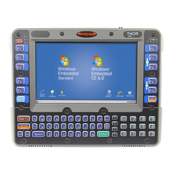
LED Functions System LEDs Connection LEDs WiFi 2nd LED Shift/CapsLock LED Shift/CapsLock LED Ctrl LED Alt LED 3 - 10... -
Page 33: System Leds
System LEDs SYS (System Status) LED UPS (Uninterruptible Power Supply) LED SSD (Solid State Drive) LED SYS (System Status) LED LED Behavior System State Solid Green • On • On but Display Off Green blinking very slowly External power present •... - Page 34 UPS Status LED The behavior of the UPS LED depends if external power is connected or not. External Power Present LED Behavior Status • No UPS charging • UPS charged Solid Green UPS charging Solid Amber • Any charging fault •...
-
Page 35: Connection Leds
Connection LEDs Bluetooth LED Wi-Fi LED WWAN LED WWAN LED LED Behavior Status Solid Green Indicates a WWAN connection to a network Indicates no WWAN connection Wi-Fi LED LED Behavior Status Solid Green Indicates a connection with an IP address to an Access Point Indicates no connection to an Access Point Bluetooth LED LED Behavior... -
Page 36: Keyboard Leds
Keyboard LEDs The keyboard LEDs are located near the specified key. 2nd LED LED Behavior Status Solid Green • Indicates the 2nd modifier key is active. 2nd mode is invoked for the next keypress only. • Pressing the 2nd key a second time exits this modifier mode and turns off the LED. 2nd mode is not invoked. -
Page 37: Touch Screen Defroster
A replaceable touch screen protective film is available when the Thor VM1 is used in an abrasive environment. Contact Technical Assistance (page 9-1) for availability. Touch Screen Defroster Extended temperature versions of the Thor VM1 contain a touch screen defroster. The touch screen defroster can be dis-... - Page 38 3 - 16...
-
Page 39: Chapter 4 - Vehicle Mounting And Accessory Installation
Introduction The Thor VM1 is designed to be mounted to a dock in a vehicle with either a RAM mount or U Bracket system. A power cable is provided with the Thor VM1 dock. An integrated scanner mount is also offered. Optional communication cables are available. -
Page 40: Cleaning
1. Locate the notch on the upper rear of the Thor VM1. 2. Slide this notch over the top lip of the dock. Slide the Thor VM1 from side to side on the dock to make sure it fully engages on the lip of the dock. -
Page 41: Dock I/O Pin Cover
• When the Thor VM1 is not installed in the dock, use the I/O Pin Cover to protect the pins on the dock as shown. • When a Thor VM1 is installed in the dock, the I/O Pin Cover can be placed out of the way behind the dock. -
Page 42: Install Ram Mount
In addition to the kits below, individual RAM mounting components are also available. Mounting Kits Each mounting kit contains: RAM Ball (Size D) for back of Thor VM1 dock with hardware (screws and washers) to attach RAM ball to dock RAM Arm (Size D), length varies by kit selected One of three mounting options: •... -
Page 43: Procedure - Ram Mount Assembly
Equipment Needed: Sockets, screwdriver and a Torque wrench capable of measuring to 50 inch pounds (5.64±.56 N/m). Note: Torquing tool is not supplied by Honeywell. Tools needed to attach the RAM Clamp Mount to the vehicle are not supplied by Honeywell. - Page 44 2.5” (63.5 mm) wide and approximately 2” (50.8 mm) thick. The clamp may be attached to a thicker beam by substituting longer bolts (not included). Be sure to position the RAM clamp mount to allow access to the switches and ports on the bottom of the Thor VM1. Bolts...
- Page 45 1. Determine the position for mounting the RAM ball plate. Be sure to position the RAM plate to allow access to the switches and ports on the bottom of the Thor VM1. 2. Attach the RAM ball plate to the vehicle mounting surface using four 1/4 bolts (not included) or equivalent fasten- ers.
- Page 46 2. Place the Thor VM1 face down on a stable surface. 3. Position the RAM ball on the rear of the Thor VM1 dock, aligning the holes on the back of the Thor VM1 dock with the holes on the RAM ball base. Attach with four M5 screws, flat washers and lock washers.
- Page 47 2. Insert the ball on the dock into the RAM arm and tighten the knob on the RAM arm using the supplied RAM wrench. Step 4 – Place the Thor VM1 into the Dock If the Thor VM1 is not already mounted to the dock, Place Thor VM1 in the Dock (page 4-18)
-
Page 48: Install U Bracket Mount
The U bracket kit is available in two configurations: • With a U Bracket included for new vehicle installations • Without a U Bracket for installing the Thor VM1 in place of a previous Honeywell vehicle mounted computer, such as a VX6 or VX7. - Page 49 The adapter bracket can be mounted in a high or low position, depending on viewing position, as shown below. Additionally, the slotted U bracket allows the Thor VM1 to be mounted vertically or tilted forward or backward for best viewing angle.
- Page 50 9. 1.25 in / 31.75 mm Step 2 - Remove RAM Ball If the Thor VM1 dock has a RAM ball attached, the RAM ball must be removed from the dock to use the U Bracket mount. Remove the RAM ball. The hardware used to attach the RAM ball to the dock is not reused for the U bracket mount.
-
Page 51: Connect Cables
For example, the largest clamp (on the left when viewing the back of the dock) is designed to secure the power cable. 2. Remove the strain relief clamp from the Thor VM1 by turning the screw counterclockwise. Put the screw aside in a safe location. -
Page 52: Connect Power
(page 4-48) - Optional connection to blank the Thor VM1 display while the vehicle is in motion. • External AC/DC Power Supply (page 4-51) - For use when DC power is not available to power the Thor VM1, such as in an office environment. Power Cable Cautions CAUTION - When routing the power cable: •... - Page 53 Power Cable Routing Power cable with right-angle connector Power cable with straight connector Avoid sharp bends in this area of the power cable 4 - 31...
- Page 54 Note: Correct electrical polarity is required for safe and proper installation. See the figures below for additional wire color-coding specifics. The Thor VM1 DC input wires (Red, Red/White DC+ and Black, Black/White DC-) and the Blue ignition input wire are galvanically isolated. The Green ground input is used for electrostatic discharge (ESD) protection.
- Page 55 Vehicle 10-60VDC Direct Power Connection 1. The Thor VM1 must not be mounted in the dock. The power switch on the dock must be turned Off. The power cable must be UNPLUGGED from the dock. 2. While observing the Fuse Requirements (page 4-32), connect the power cable as close as possible to the actual battery terminals of the vehicle (if using unswitched power).
- Page 56 When switched vehicle power is available the Thor VM1 ignition signal wire can be connected (less than 1mA over input voltage range) to the switched circuit to allow the Thor VM1 to power on when the vehicle is switched on and go into shut down (see note below) when the vehicle is switched off.
- Page 57 Auto-On Control Wiring Diagram Auto-On must be selected on the AutoOn (page 5-5) control panel. The vehicle supply connections should be made to vehicle switched power to allow the terminal to automatically power-up when vehicle power is switched on or when the power switch on the back of the dock is placed in the On position. The Ignition wire is not used and should be left disconnected.
- Page 58 Manual Control Wiring Diagram Ignition wire must be left unconnected Standard must be selected from the AutoOn (page 5-5) control panel. Existing Circuitry On Vehicle Quick Mount Smart Dock Battery Main Switch Cable for optional COM1 or COM2 screen blanking Connector connection Fuse - See...
- Page 59 60-144 VDC Vehicles (50-150 VDC Power Supply, Screws on Side of Lid) This option requires DC/DC external power supply Honeywell Part no. 9000313PWRSPLY. Shown With Lid Attached Shown With Lid Removed • Lid is secured with screws on the side of lid.
- Page 60 Wiring Diagram (page 4-40), before beginning power cable install. 2. The Thor VM1 must not be mounted in the dock. The power switch on the dock must be turned Off. The power cable must be UNPLUGGED from the dock. 3. Route the cable from the Thor VM1 to the DC/DC power supply. Route the power cable the shortest way pos- sible.
- Page 61 17. Connect the watertight connector end of the power cable to the Thor VM1 dock power connector by aligning the connector pins to the power connector; push down on the watertight connector and twist it to fasten securely.
- Page 62 Wiring Diagram Existing Circuitry on Vehicle Quick Mount Smart Dock Forklift Battery Main Switch User supplied serial cable for optional COM1 or COM2 screen blanking Connector connection, on Dock Fuse - See see below Warning statement below See Caution statement Red/White (if present) below Black/White (if present)
- Page 63 60-144 VDC Vehicles (50-150 VDC Power Supply, Screws on Top of Lid) This option requires DC/DC power supply Honeywell Part no. VX89303PWRSPLY, shown below. Shown With Lid Attached Shown With Lid Removed • Lid is secured with screws on the top of lid.
- Page 64 Wiring Diagram (page 4-40), before beginning power cable install. 2. The Thor VM1 must not be mounted in the dock. The power switch on the dock must be turned Off. The power cable must be UNPLUGGED from the dock. 3. Route the cable from the Thor VM1 to the DC/DC power supply. Route the power cable the shortest way pos- sible.
- Page 65 16. Connect the watertight connector end of the power cable to the Thor VM1 dock power connector by aligning the connector pins to the power connector; push down on the watertight connector and twist it to fasten securely.
- Page 66 Wiring Diagram Existing Circuitry on Vehicle Quick Mount Smart Dock Forklift Battery Main Switch User supplied serial cable for optional COM1 or COM2 screen blanking Connector connection, Fuse - See see below Warning statement below See Caution statement below Red/White (if present) Black/White (if present) Power Black...
- Page 67 VX6 / VX7 Adapter Cable An adapter cable is available to attach the Thor VM1 to a vehicle previously equipped with a VX6/VX7 DC power cable. The adapter cable has a 5-pin connector to match with the VX6/VX7 power supply cable on one end and a 6-pin con- nector to match to the Thor VM1 on the other end.
- Page 68 Thor VM1 on the other end. The cable also has bare wires for ground and ignition sense connection plus a D9 cable to connect to a COM port on the Thor VM1 dock to provide a screen blanking signal. This section assumes the VX8/VX9 power cable is properly connected to vehicle power.
- Page 69 The adapter cable has a 5-pin connector to match with the VV61 power supply cable on one end and a 6-pin connector to match to the Thor VM1 on the other end. This section assumes the CV61 power cable is properly connected to vehi- cle power.
- Page 70 1. Connect the gray wire of the cable to the switched side of the Screen Blanking Box. 2. Connect the black wire of the cable to the unswitched side of the Screen Blanking Box. 3. Connect the D9 serial connector to either COM1 or COM2 serial port on the Thor VM1 dock. 4 - 48...
- Page 71 2. Connect the wire from Pin 7 of the cable to the unswitched side of the Screen Blanking Box or to a user- supplied switch. 3. Connect the D9 serial connector to either COM1 or COM2 serial port on the Thor VM1 dock. Screen Blanking Box...
-
Page 72: Screen Blanking With Switch
To pin 7 of COM1 or COM2 To pin 8 of COM1 or COM2 Note: The black and gray wire colors in the illustration only apply to the optional Honeywell Screen Blanking Box Cable, VM1080CABLE. The wire colors may be different in a user-supplied cable. - Page 73 3. Connect the DC Output Cable end to the corresponding connector on the adapter cable. 4. Connect the watertight connector end of the adapter cable to the Thor VM1 dock power connector by aligning the connector pins to the power connector; push down on the watertight connector and twist it to fasten securely.
-
Page 74: Connect Usb Host
Strain Relief Cable Clamps (page 4-29). Connect USB Client Note: The USB client connection is not used on Thor VM1 with a Windows Embedded Standard operating system. Connect Serial Device Note: Pin 9 of the COM port is configured to provide +5V. -
Page 75: Connect Headset Cable
2. Tighten the thumbscrews in a clockwise direction. Do not over tighten. click! 3. Slide the cable ends together until they click shut. Do not twist or bend the connectors. The Thor VM1 internal microphone and speakers are automatically disabled when the headset is connected. - Page 76 1. Do not twist the microphone boom when adjusting the microphone. The microphone should be adjusted to be about two finger widths from your mouth. 2. Make sure the microphone is pointed at your mouth. Note the small “Talk” label near the mouthpiece. Make sure the Talk label is in front of your mouth.
-
Page 77: Connect Canbus Cable
Connect CANbus Cable The CANbus/Audio connector supports a headset adapter cable or a CANbus Y cable. The Thor VM1 does not support connecting audio and CANbus simultaneously. CANbus / Audio Connector (page 8-7) for connector pinouts. 1. Seat the D15 cable end connector firmly over the CANbus/Audio Connector on the dock. -
Page 78: Install Remote Antenna
(base plate and right angle), cable, and antenna. Tools are not included. The desired remote antenna bracket is mounted on the top of a forklift, truck or other vehicle and cabled to the Thor VM1 inside the vehicle. The Vehicle Remote Mount Antenna cannot be used by devices with an internal antenna. - Page 79 6. Connect the cable to the antenna connector (Wi-Fi Main or Wi-Fi Aux) on the Thor VM1. If only one antenna is used, be sure to connect it to the Wi-Fi Main connector.
- Page 80 The Remote Antenna Installation Kit consists of the WAN antenna and an extension cable. The remote antenna is mounted on the top of a forklift, truck or other vehicle and cabled to the Thor VM1 inside the vehicle. 1. Locate a mounting position on highest point on the vehicle, following these precautions: •...
-
Page 81: Apply Touch Screen Protective Film
It is easiest to start with one of the bottom corners. 5. Slide the protective film away from the other bottom corner. The film may bulge slightly away from the Thor VM1 as it is being slid. -
Page 82: Disconnect Ups Battery
Thor VM1. 8. Reattach the access panel, torquing the M3 screws to 4-5 inch pounds using a #2 Phillips bit. 9. When the Thor VM1 is attached to external power, the UPS battery is automatically reconnected. -
Page 83: Install Sd Card
Installation Procedure 1. For convenience, the Thor VM1 can be removed from the dock, though it is not necessary. 2. If the Thor VM1 remains in the dock, disconnect the power cable from the dock. 3. Shutdown the Thor VM1. -
Page 84: Install Sim Card
Install SIM Card A SIM card may be required for WWAN. Note: The SIM card is not hot-swappable. After installing or removing a SIM card, the Thor VM1 must be rebooted for the change to take effect. Equipment Required The following equipment is user-supplied: •... -
Page 85: Replace Front Panel
Front Panel Options The front panel of the Thor VM1 is field replaceable. The front panel assembly contains the keypad, touch screen and optional defroster. Should any of these components fail, the front panel assembly can easily be replaced to reduce down- time. - Page 86 7. Position the replacement front panel so the tab on the back of the front panel lines up with the slot on the Thor VM1. Be sure the two wiring connectors are also aligned. 8. Position the replacement front panel so wiring connector on the back of the front panel lines up with the connector on the Thor VM1.
-
Page 87: Replace Ups Battery
Replace UPS Battery The UPS battery in the Thor VM1 is field replaceable. Should the UPS battery fail, it can easily be replaced to minimize down- time. Equipment Required The following equipment is user-supplied: • Torquing tool capable of measuring inch pounds •... - Page 88 Thor VM1 on Thor VM1 13. Position the front panel so the tab on the back of the front panel lines up with the slot on the Thor VM1. Be sure the two wiring connectors are also aligned. 14. Gently press the front panel into place.
-
Page 89: Chapter 5 - Software
After the system files are processed, Microsoft Windows begins to load. Windows maintains a System Registry and INI files. Standard Windows configuration options apply to the Thor VM1. Configuration options are located in the System Tray or the Control Panel: •... - Page 90 Summit Client Utility (Start) > Control Panel > Wi-Fi, or SCU icon on desktop Manage the wireless 802.11 client installed in the Thor VM1. If the Summit Client Utility is not present, the Laird Configuration Manager may be installed. Freefloat Link*One Wedge Link*One bar code decoder configuration software is installed on the Thor VM1.
-
Page 91: Control Panel
The Versions tab displays the versions of many of the software programs installed. Not all installed software is included in this list and the list varies depending on the applications loaded on the Thor VM1. The Image line displays the revi- sion of the system software installed. - Page 92 Network IP MAC Address The Network IP tab displays the MAC address of the network card(s) such as the Summit WLAN radio and the Bluetooth module. 5 - 4...
-
Page 93: Autoon
When the Thor VM1 is on, the behavior of the power button press is configurable using the control panel. Ignition Control The Thor VM1 is turned on automatically when a signal is received via the Ignition Input wire, which is part of the DC Power Cable. -
Page 94: Bluetooth
• It is not necessary to disconnect a paired scanner and printer before a different scanner or printer is paired with the Thor VM1. • The target Bluetooth device should be as close as possible (up to 32.8 ft (10 meters) Line of Sight) to the Thor VM1 during the pairing process. - Page 95 Tap Stop at any time to end the Discover and Query for Unique Identifier functions. Note: When an active paired device enters Suspend Mode, is turned Off or leaves the Thor VM1 Bluetooth scanning range, the Bluetooth connection between the paired device and the Thor VM1 is lost. There may be audible or visual signals as paired devices disconnect from the Thor VM1.
- Page 96 The Bluetooth panel assigns an icon to the device name. An icon with a red background indicates the device's Bluetooth connection is inactive. An icon with a white background indicates the device is connected to the Thor VM1 and the device's Bluetooth connection is active.
- Page 97 Computer is connectable This option is Enabled by default. Disable this option to inhibit Thor VM1 connection initiated by a Bluetooth scanner. Computer is discoverable This option is Disabled by default. Enable this option to ensure other devices can discover the Thor VM1.
- Page 98 (Filtered Mode is disabled/unchecked) or the discovery result displays Bluetooth scanners and printers only (Filtered Mode is enabled/checked). When Filtered Mode is disabled, the Thor VM1 can pair with up to four Bluetooth de- vices. A Restart is required every time Filtered Mode is toggled on and off.
- Page 99 Reconnect Note: These options can still be checked or unchecked whether Bluetooth connection is enabled or disabled. Options Option Function Report when connection This option is Enabled (checked) by default. lost There may be an audio or visual signal when a connection between a paired, active device is lost.
- Page 100 (Start) > Control Panel > Bluetooth or Bluetooth icon in taskbar or Bluetooth icon on desktop Tap the Bluetooth icon in the taskbar to open the Bluetooth EZPair application. The Thor VM1 default Bluetooth setting is Enabled. ® The Thor VM1 Bluetooth module is designed to Discover and pair with nearby Bluetooth devices.
- Page 101 9. Upon successful pairing, the selected device may react to indicate a successful connection. The reaction may be an audio signal from the device, flashing LED on the device, or a dialog box is placed on the Thor VM1 dis- play.
- Page 102 (Start) > Control Panel > Bluetooth or tap the Bluetooth icon on the desktop or tap the Bluetooth icon in the taskbar. Locate the bar code label, similar to the one shown above, attached to the Thor VM1. The label is the Bluetooth address identifier for the Thor VM1.
- Page 103 1. Scan the Bluetooth address bar code label, attached to the Thor VM1, with the Bluetooth mobile scanner. 2. If this is the first time the Bluetooth scanner has scanned the Thor VM1 Bluetooth label, the devices are paired. See section titled Bluetooth Beep and LED Indications (page 5-16).
- Page 104 Contact Technical Assistance (page 9-1) for Bluetooth product assistance. Note: If there is no beep or no LED flash from the Bluetooth managed printer, the Thor VM1 and the printer are currently paired. Easy Pairing and Auto-Reconnect The Bluetooth module can establish relationships with new devices after the user taps the Discover button.
-
Page 105: Display
Display (Start) > Control Panel > Display (Classic View) (Start) >Control Panel > Appearance and Themes (Category View) The Thor VM1 supports a 800x480 pixel display resolution. Screen Rotation (page 5-23), Screen Blanking (page 5-21), Defroster Control (page 5-22) and... -
Page 106: Power Options
Power Options Select a Power Scheme Power schemes can be configured for when the Thor VM1 is attached to an external power supply or when operating from the UPS battery. View UPS Battery Status Power Meter (Start) > Control Panel > Power Options > Power Schemes tab (Classic View) (Start) >... - Page 107 • Ask me what to do • Stand by • Shut down. The default is to shut down. The Thor VM1 performs an orderly shut down when the power key is pressed when this option is enabled. 5 - 19...
- Page 108 (Start) >Control Panel > Performance and Maintenance> Power Options > Hibernate tab (Category View) By default, hibernate is disabled on the Thor VM1. The default can be changed on this page. The disk space necessary for hibernation plus the free disk space on the hard drive are listed.
-
Page 109: Screen Control
Note: If automatic brightness control is enabled for an outdoor display, the value for LCD brightness depends on the Ambient Light %. Note: There is no default value for Ambient Light % as it varies depending on the level of light where the Thor VM1 is located. - Page 110 Use the Screen on delay to specify the period of time in ms (milliseconds) between when the vehicle stops and the Thor VM1 screen turns on. For example, use the delay if the switch end of the cable is attached to the vehicle’s accel- erator pedal.
-
Page 111: Screen Rotation
• Use function keys - press the 2nd key then F9 to adjust volume up or 2nd then F10 to adjust volume down. User Accounts Note: The following applies to a Thor VM1 that is not part of a domain. When the Thor VM1 is part of a domain, the user is prompted for credentials at Windows startup or log on. -
Page 112: Wi-Fi
Administrator account at Windows startup. If the user assigns a password to the Administrator account: • The password is stored and used when the Thor VM1 logs onto the Administrator account at Windows startup. The user is not prompted to enter a password. -
Page 113: Bar Code Readers
The Thor VM1 can use the following external bar code readers: • Tethered hand-held scanners are tethered to a serial port or a USB host port (via a dongle cable) on the Thor VM1 Smart Dock and are configured by scanning the engine-specific bar codes in the scanner manufacturer's programming guide. The manufacturer's guides are usually shipped with the bar code reader. -
Page 114: Bios
The second device is the Windows CE Image. If a USB drive, such as a thumb drive is attached to the Thor VM1, the device attempts to boot from the USB drive: • If the USB drive contains a bootable sector, the Thor VM1 boots from the USB drive. -
Page 115: Thor Vm1 Recovery Dvd
Thor VM1 Recovery DVD A recovery DVD is available to restore the operating system on your Thor VM1 to the same state it had when it was shipped from the factory. Recovery DVDs are available for English, Traditional Chinese, Simplified Chinese, Japanese, Korean, French, Spanish, Germain and Thai languages.. - Page 116 5 - 28...
-
Page 117: Chapter 6 - Wireless Network Connections
WEP encryption or WPA security. Important Notes It is important that all dates are correct on the Thor VM1 and host computers when using any type of certificate. Cer- tificates are date sensitive and if the date is not correct authentication will fail. -
Page 118: Wireless Zero Config Utility
2. A message appears that a Power Cycle is required to make settings activate properly. 3. Tap OK. 4. Restart the Thor VM1. The Summit Client Utility passes control to Wireless Zero Config and the WZC Wireless Information control panel. -
Page 119: Main
Main Start > All Programs > Summit > Summit Client Utility > Main tab Factory Default Settings Admin Login SUMMIT Radio Enabled Active Config/Profile Default Regulatory Domain FCC, ETSI or Worldwide The Main tab displays information about the wireless client device including: •... - Page 120 Admin Login To login to Administrator mode, tap the Admin Login button. Once logged in, the button label changes to Admin Logout. The admin is automatically logged out when the SCU is exited. The Admin can either tap the Admin Logout button, or the OK button to logout. Enter the Admin password (the default password is SUMMIT and is case sensitive) and tap OK.
-
Page 121: Profile
Profile Start > All Programs > Summit > Summit Client Utility > Profile tab Note: Tap the Commit button to save changes before leaving this panel or the SCU. If the panel is exited before tapping the Commit button, changes are not saved! Factory Default Settings Profile Default... - Page 122 Buttons Button Function Commit Saves the profile settings made on this screen. Settings are saved in the profile. Credentials Allows entry of a username and password, certificate names, and other information required to authen- ticate with the access point. The information required depends on the EAP type. Delete Deletes the profile.
- Page 123 It is important the Radio Mode parameter correspond to the AP to which the device is to connect. For example, if this parameter is set to G rates only, the Thor VM1 may only connect to APs set for G rates and not those set for B and G rates.
-
Page 124: Status
Status Start > All Programs > Summit > Summit Client Utility > Status tab This screen provides information on the radio: • The profile being used. • The status of the radio card (down, associated, authenticated, etc.). • Client information including device name, IP address and MAC address. •... -
Page 125: Diags
Diags Start > All Programs > Summit > Summit Client Utility > Diags tab The Diags screen can be used for troubleshooting network traffic and radio connectivity issues. • (Re)connect – Use this button to apply (or reapply) the current profile and attempt to associate or authenticate to the wireless LAN. -
Page 126: Global
Global Start > All Programs > Summit > Summit Client Utility > Global tab The parameters on this panel can only be changed when an with a password. The current values for the parameters can be viewed by the general user without requiring a password. Note: Tap the Commit button to save changes. - Page 127 Custom Parameter Option The parameter value is displayed as “Custom” when the operating system registry has been edited to set the Summit parameter to a value that is not available from the parameter’s drop down list. Selecting Custom from the drop down list has no effect.
- Page 128 Parameter Default Function Aggressive Scan When set to On and the current connection to an AP weakens, the radio aggressively scans for available APs. Aggressive scanning works with standard scanning (set through Roam Trigger, Roam Delta and Roam Period). Aggressive scanning should be set to On unless there is significant co-channel interference due to over- lapping APs on the same channel.
- Page 129 Tray Icon Determines if the Summit icon is displayed in the System tray. Options are: On, Off The tray icon is not displayed when the Thor VM1 is running a Windows Embedded Standard 2009 operating system. Hide Password When On, the Summit Config Utility masks passwords (characters on the screen are displayed as an *) as they are typed and when they are viewed.
- Page 130 Logon Options There are two options available, a Single Signon (page 6-14) option which uses the Windows username and password as the credentials for 802.1x authentication and a Pre-Logon Connection (page 6-14) option which uses saved creden- tials for 802.1x authentication before Windows logon. If either option is enabled, the credentials entered here take precedence over any credentials entered on the profile tab.
-
Page 131: Sign-On Vs. Stored Credentials
The user must enter the Username and Password at that time to authenticate. • When using Summit with the Thor VM1, there is an option on the Global tab to use the Windows user name and password to log on instead of any username and password stored in the profile. - Page 132 To Use Stored Credentials 1. After completing the other entries in the profile, click on the Credentials button. 2. Enter the Username and Password on the Credentials screen and click the OK button. 3. Click the Commit button. 4. For LEAP and WPA/LEAP, configuration is complete. 5.
-
Page 133: Windows Certificate Store Vs. Certs Path
Windows Certificate Store vs. Certs Path Note: It is important that all dates are correct on the Thor VM1 and host computers when using any type of certificate. Certificates are date sensitive and if the date is not correct authentication will fail. -
Page 134: Configuring The Profile
Certs Path 1. See Generate a Root CA Certificate (page 6-32) and follow the instructions to download the Root Certificate to a PC. 2. Copy the certificate to specified directory on the mobile device. The default location for Certs Path is C:\Pro- gram Files\Summit\certs. - Page 135 No Security To connect to a wireless network with no security, make sure the following profile options are used. 1. Enter the SSID of the Access Point assigned to this profile 2. Set EAP Type to None 3. Set Encryption to None 4.
- Page 136 To connect using WEP, make sure the following profile options are used. 1. Enter the SSID of the Access Point assigned to this profile 2. Set EAP Type to None 3. Set Encryption to WEP or Manual WEP (depending on SCU version) 4.
- Page 137 LEAP To use LEAP (without WPA, also called WEP-LEAP), make sure the following profile options are used. 1. Enter the SSID of the Access Point assigned to this profile 2. Set EAP Type to LEAP 3. Set Encryption to WEP EAP or Auto WEP (depending on SCU version) 4.
- Page 138 PEAP/MSCHAP To use PEAP/MSCHAP, make sure the following profile options are used. 1. Enter the SSID of the Access Point assigned to this profile 2. Set EAP Type to PEAP-MSCHAP 3. Set Encryption to WPA TKIP 4. Set Auth Type to Open To use another encryption type, select WPA CCKM, WPA2 AES or WPA2 CCKM for encryption and complete other entries as detailed in this section.
- Page 139 If using the Windows certificate store: 1. Check the Use MS store checkbox. The default is to use the Full Trusted Store. 2. To select an individual certificate, click on the Browse button. 3. Uncheck the Use full trusted store checkbox. 4.
- Page 140 PEAP/GTC To use PEAP/GTC, make sure the following profile options are used. 1. Enter the SSID of the Access Point assigned to this profile 2. Set EAP Type to PEAP-GTC 3. Set Encryption to WPA TKIP 4. Set Auth Type to Open To use another encryption type, select WPA CCKM, WPA2 AES or WPA2 CCKM for encryption and complete other entries as detailed in this section.
- Page 141 If using the Windows certificate store: 1. Check the Use MS store checkbox. The default is to use the Full Trusted Store. 2. To select an individual certificate, click on the Browse button. 3. Uncheck the Use full trusted store checkbox. 4.
- Page 142 WPA/LEAP To use WPA/LEAP, make sure the following profile options are used. 1. Enter the SSID of the Access Point assigned to this profile 2. Set EAP Type to LEAP 3. Set Encryption to WPA TKIP 4. Set Auth Type as follows: 5.
- Page 143 RADIUS server. The RADIUS server must have auto provisioning enabled to send the PAC provisioning credentials to the Thor VM1. For automatic PAC provisioning, once a username/password is authenticated, the PAC information is stored on the Thor VM1.
- Page 144 To use Stored Credentials: • Enter the Domain\Username (if the Domain is required), otherwise enter the Username. • Enter the password. To use Automatic PAC Provisioning: • No additional entries are required. To use manual PAC Provisioning: • Enter the PAC Filename and PAC Password. •...
- Page 145 EAP-TLS To use EAP-TLS, make sure the following profile options are used. 1. Enter the SSID of the Access Point assigned to this profile 2. Set EAP Type to EAP-TLS 3. Set Encryption to WPA TKIP 4. Set Auth Type to Open To use another encryption type, select WPA CCKM, WPA2 AES or WPA2 CCKM for encryption and complete other entries as detailed in this section.
- Page 146 3. Click OK then click Commit. The Thor VM1 should be authenticating the server certificate and using EAP-TLS for the user authentication. Ensure the correct Active Profile is selected on the Main tab and restart. The SCU Main tab shows the device is asso- ciated after the radio connects to the network.
- Page 147 WPA PSK To connect using WPA/PSK, make sure the following profile options are used: 1. Enter the SSID of the Access Point assigned to this profile 2. Set EAP Type to None 3. Set Encryption to WPA PSK or WPA2 PSK 4.
-
Page 148: Certificates
Certificates are date sensitive and if the date is not correct authentication will fail. The easiest way to get the root CA certificate is to use a browser on a PC or the Thor VM1 to navigate to the Certificate Authority. - Page 149 Click the Download a CA certificate, certificate chain or CRL link. Make sure the correct root CA certificate is selected in the list box. Click the DER button. To download the CA certificate, click on the Download CA certificate link. 6 - 33...
-
Page 150: Install A Root Ca Certificate
C:\Program Files\Summit\certs folder or other path specified in the Summit Certs global parameter. Copy the certificate file to the Thor VM1. The certificate file has a .CER extension. Locate the file and double-tap on it. If presented with a security warning, confirm that you want to open the file. -
Page 151: Generate A User Certificate
3. An import successful message is displayed. Generate a User Certificate The easiest way to get the user certificate is to use the browser on the Thor VM1 or a PC to navigate to the Certificate Authority. To request the user certificate, open a browser to http://<CA IP address>/certsrv. - Page 152 The User Certificate is issued. Install the user certificate on the requesting computer by clicking the Install this certificate link. If the requesting computer is the Thor VM1, then the process is finished. Otherwise, export the certificate as described below.
-
Page 153: Install A User Certificate
.PFX extension. Click Finish and OK to close the Successful Export message. Locate the User Certificate in the specified location. Copy to the Thor VM1. Install the User certificate. Install a User Certificate After generating and exporting the user certificate, install the user certificate. - Page 154 1. Copy the certificate from the PC to the Thor VM1. 2. Locate the certificate file (it has a .PFX extension) and double-click on it. If clicking on the certificate file does not launch the certificate import wizard, follow the...
- Page 155 4. The Certificate Import Wizard starts. 5. Tap Next and use the Browse.. button to locate the User certificate copied to the Thor VM1. If necessary, change the file type drop down list at the bottom of the explorer window from *.cer to *.pfx. After selecting the .PFX file, tap Open.
-
Page 156: Oneclick Internet
If this delay is acceptable to the user, standby may be enabled. When the One Click Internet utility is displayed on screen and the Thor VM1 enters standby, the touch screen may remain inactive for 10-15 seconds after the Thor VM1 resumes from standby. - Page 157 Activation This step is only necessary for Verizon. You need the IMEI number for the Thor VM1 when you contact Verizon prior to activating service on the Thor VM1. The IMEI number can be found on the Info (page 6-50) tab.
- Page 158 This screen contains the settings including the telephone number from the provider, in this case Verizon. 6 - 42...
-
Page 159: Using Oneclick Internet
Using OneClick Internet If OneClick Internet is not loaded, double-tap the desktop icon to load it. If OneClick Internet is loaded but minimized to the system tray, tap the OneClick Internet icon in the system tray to maximize it. Connection Management 1. -
Page 160: Menu Buttons
Update Button OneClick Internet provides a built-in online update functionality that allows for an automatic update of OneClick Internet application, device drivers, and APN database. Honeywell DOES NOT recommend using this option. Contact Technical Assistance (page 9-1) or information on upgrading to another version of OneClick Internet. - Page 161 Settings Button Access the Settings menu by tapping the Settings button on the main window. The following tabs are available: • Profile • Network • History • PIN • Info • Firmware • General Profile Create a connection profile to store connection information. Once a profile has been created, its name appears in the drop down Profiles list, which replaces the Profile Name text box in the illustration above.
- Page 162 Buttons Button Description Create a new profile. When this option is selected, the Profile Name is a text box. Enter a name for the profile as well as other connection specific configuration. When finished, tap the Save button to save the new profile. Edit a current profile.
- Page 163 Network The appearance of the network tab depends on the type of firmware selected. Network with SIM Card Select Connection Label Description Select automatically Selects the best suited network automatically Use GPRS/EDGE only Use only GPRS/EDGE for a connection Use UMTS/HSPA only Use only UMTS/HSPA for a connection.
- Page 164 CDMA Network Information on the CDMA network is displayed. There are no editable parameters on this screen. History The history shows the data volume transferred in a specified time frame. Select the From and To dates to see the data volume sent/received in the specified period. Tap Reset to reset the counter. 6 - 48...
- Page 165 You can Activate/Deactivate the PIN or Change the PIN. Activate/Deactivate PIN This tab is only displayed when a firmware is loaded that requires a SIM card (such as AT&T or T-Mobile). By default, you have to enter the PIN each time you start WebToGo OneClick Internet using a modem card. Deactivate the PIN to avoid entering the PIN each time.
- Page 166 Info This tab displays SIM card, modem and system Information. Firmware OneClick Internet selects the correct Firmware matching your operator automatically, if a special firmware for your operator is available and a SIM card is inserted. If no specific firmware for your operator is available, generic firm- ware is selected.
- Page 167 If you cancel the activation or if it fails, you can also start the activation manually by pressing the Activate but- ton on the General tab. General Label Description Auto Launch When selected OneClick Internet launches automatically when the user starts the Thor VM1 and logs in. Connect Automati- When selected OneClick Internet automatically connects on start-up. cally Reconnect Auto-...
- Page 168 Label Description Gobi NDIS Auto When selected OneClick Internet connects automatically after powering up the operating Connect system and before the user logs in. Application Use the Application tab to specify any application to launch automatically once the Internet connection is estab- lished.
-
Page 169: Application Buttons
Application Buttons The SMS Center window is split into menu bar, folder view, folder content and preview window. To manage your short messages you may: Button Description Manage SMS folders Change SMS settings Create new SMS/MMS messages Reply to SMS Forward SMS Move SMS to a folder Delete SMS... - Page 170 Button Description Send and receive SMS/MMS (if supported) Manage phone book contacts on SIM and in Email client. Folder By using this menu, you may change the folder structure of the SMS Center: Button Description New Folder Creates a new folder, name has to be unique Rename Renames an existing folder Remove...
- Page 171 Move SMS.. Highlight the SMS to be moved and click the “Move SMS” button. A small window opens that lets you select the destination folder. Select the folder to which the message should be moved, then click “Move”. Delete Highlight the SMS which you want to delete. Click “Delete” to remove the message. Send/Receive Messages will be sent and/or received by clicking on this button.
-
Page 172: About
Web Browser Clicking this button opens the Web Browser and allows the user to surf the Internet once the connection is established. The default browser is used, which is Internet Explorer by default on the Thor VM1. Email Clicking this button opens the Email application after the connection is established. The Email application is the default Email client set in the Control Panel (Start >... - Page 173 One Click Internet is pre-installed before the Thor VM1 is shipped. If you have an installed version of OneClick Internet and need to update to a newer version, you must uninstall the previous version first by selecting Start > Control Panel and select Add or Remove Programs. Select OneClick Internet and tap Remove.
- Page 174 Next the installer asks for the installation directory. Use the Browse button to specify a location other than the default. Installation process is indicated on screen. When completed. click the Finish button to exit the installer. Start OneClick Internet from the Windows Program Menu or double-tap the desktop icon. 6 - 58...
-
Page 175: Oneclick Internet Connection Manager
OneClick Internet Connection Manager Launch OneClick Internet from the desktop icon or Windows Start Menu. When OneClick Internet is active, a status icon appears in the system tray. The main screen for OneClick Internet opens when the application is started. This screen displays basic information on the connection as well as access to more advanced features and details. - Page 176 Connection Management Refer to the table below for descriptions of the items in the connection management area. Icon Description Network signal strength Additionally the network name is displayed to the right of the icon. The more green bars, the stronger the signal.
- Page 177 Information Buttons Icon Description Radio On/Off Tap this button to switch the radio state. The color of this button also indicates the state of the radio: The radio is On. Tap the button to turn the radio Off. The radio is Off. Tap the button to turn the radio On. The radio is Connecting or the radio has been disabled.
- Page 178 6 - 62...
-
Page 179: Chapter 7 - Key Maps
64-Key QWERTY Keypad Key Map • Because the keyboard only has 64 keys, all functions are not visible (or printed on the keyboard). Therefore the Thor VM1 keyboard supports what is called hidden keys -- keys that are accessible but not visible on the keyboard. - Page 180 To get this Key / Function Press These Keys in this Order Ctrl-Break Pause Up Arrow Up Arrow Down Arrow Down Arrow Right Arrow Right Arrow Left Arrow Left Arrow Page Up Up Arrow Page Down Down Arrow Right Arrow Home Left Arrow F1 - F10...
- Page 181 To get this Key / Function Press These Keys in this Order Shift Shift Shift Shift Shift Shift Shift Shift Shift Shift Shift Shift Shift Shift Shift Shift Shift Shift Shift Shift Shift Shift Shift " . (VK_PERIOD) 7 - 3...
- Page 182 To get this Key / Function Press These Keys in this Order & > < Shift Shift Shift Shift Shift Shift & Shift Shift Shift Shift 7 - 4...
-
Page 183: Chapter 8 - Specifications And Reference Material
Specifications and Reference Material Technical Specifications Thor VM1 Processor Atom CPU operating at 1.6 GHz Memory 2 GB SDRAM Mass Storage 4 or 8 GB CompactFlash memory card Storage Expansion User installable, supports 1 to 4GB SD card Operating System... -
Page 184: Vm1D Dock
VM1D Dock Power Connector 6-pin connector: Direct10-60V DC input power Optional external converters for AC (90-240 VAC) and extended range DC (60-150 VDC) COM1Connector 9-pin male, RS-232 serial port, COM1 with power on pin 9 COM2 Connector 9-pin male, RS-232 serial port, COM2 with power on pin 9 CANBUS/AUDIO Connector 15-pin male, CANbus/Audio connector supports either audio/microphone via adapter cable or J1939 Female and J1939 Male connectors via CANbus cable... -
Page 185: Dimensions
Dimensions Thor VM1 Width 10.6” (26.8 cm) Height 8.4” (21.4 cm) Depth 1.7” (4.3 cm) Weight 5.6 lb. (2.5 kg) Dock Note: The RAM ball is not included in the following measurements. Length 7.1” (18.0 cm) Width 6.1” (15.5 cm) Height 2.5”... -
Page 186: Environmental Specifications
Environmental Specifications Thor VM1 and Dock Operating Temperature Standard: -4°F to 122°F (-20°C to 50°C) [non-condensing] Cold Storage: -22º to 122º F (-30ºC to 50ºC) [condensing] Storage Temperature Standard and Cold Storage: -22°F to 140°F (-30°C to 60°C) [non-condensing] 8 KV air, 4kV direct contact Operating Humidity Standard: Up to 90% non-condensing at 104°F (40°C) -
Page 187: Port And Connector Pinouts
Port and Connector Pinouts Power Supply Connector Signal Description V In+ 10-60V DC input + V In+ 10-60V DC input + V In- input - V In- input - Chassis ground Ignition +0V to 60V to start terminal COM1 and COM2 Connector Signal Description Data Carrier Detect –... -
Page 188: Usb Connector
PIN 4 USB_H1_D- USB D- PIN 1 USB_H1_D+ USB D+ USB Power Return Shell CGND Chassis Ground USB Client Connector The USB client connection is not supported on the Thor VM1 with the Windows Embedded Standard operating system. 8 - 6... -
Page 189: Canbus / Audio Connector
CANbus / Audio Connector Signal Name Description CAN reserved PIN 1 PIN 5 PIN 6 PIN 10 CAN_L CAN_L bus line dominant low CAN_GND CAN Ground CAN reserved PIN 11 PIN 15 Optional ground Audio return Headset return Audio output Headset output Mic input Microphone input... - Page 190 CANbus Y Cable D15 Female Connector Signal Description Not Used PIN 5 PIN 1 PIN 10 PIN 6 CAN_L CAN_L bus line dominant low CAN_GND CAN ground Not Used CAN reserved PIN 15 PIN 11 Ground Not used Not used Not used Not used Not used...
-
Page 191: Hat Encoding
Hat Encoding 8 - 9... - Page 192 8 - 10...
-
Page 193: Chapter 9 - Customer Support
Limited Warranty Honeywell International Inc. (“HII”) warrants its products to be free from defects in materials and workmanship and to conform to HII’s published specifications applicable to the products purchased at the time of shipment. This warranty does not cover any HII product which is (i) improperly installed or used;... - Page 194 The duration of the limited warranty for the Thor VM1 internal UPS battery is 1 year. The duration of the limited warranty for the Thor VM1 AC power supply and cables is 1 year. The duration of the limited warranty for the Thor VM1 DC/DC power supply is 1 year.
- Page 195 Back Cvr - 1...
- Page 196 Honeywell International Inc. 9680 Old Bailes Road Fort Mill, SC 29707 www.honeywellaidc.com ™ VM1-WIN-UG Rev D 4/17...