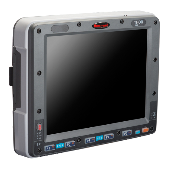
Honeywell Thor VM2 Reference Manual
Vehicle-mount computer
Hide thumbs
Also See for Thor VM2:
- User manual (398 pages) ,
- Reference manual (196 pages) ,
- Quick start manual (12 pages)

Related Manuals for Honeywell Thor VM2


Summary of Contents for Honeywell Thor VM2
- Page 1 Thor™ VM2 Vehicle-Mount Computer Microsoft® Windows® Embedded CE 6 Operating System Vehicle Mounting Reference Guide...
- Page 2 Disclaimer Honeywell International Inc. (“HII”) reserves the right to make changes in specifications and other information contained in this document without prior notice, and the reader should in all cases consult HII to determine whether any such changes have been made. The information in this publication does not represent a commitment on the part of HII.
- Page 3 Lithium Battery Safety Statement Caution: Lithium battery inside. Danger of explosion if battery is incorrectly replaced. Replace only with same or equivalent type recommended by battery manufacturer. (US) Attention: Contient une pile de lithium. Risque d’explosion dans le cas où la pile ne serait pas correctement remplacée. Remplacer uniquement avec une pile semblable ou equivalente au type de pile recommandé...
- Page 4 Legend: Chinese – CN; Danish – DK; Dutch – NL; English – US; Finnish – FI; French – FR; German – DE; Greek – GR; Italian – IT; Japanese – JP; Korean – KR; Norwegian – NO; Portuguese – PT; Spanish – ES; Swedish – SE; Turkish – TR.
- Page 5 Vehicle Power Supply Connection Safety Statement Vehicle Power Supply Connection: If the supply connection is made directly to the battery, a ten A slow-blow fuse should be installed in the positive lead within 5 inches (12.7 cm.) of the battery positive (+) terminal. (US) Raccordement de l’alimentation du véhicule Si l’alimentation est raccordée directement à...
-
Page 7: Table Of Contents
Step 1c – Attach RAM Plate to Vehicle and Attach RAM Ball Mounting Dimensions Step 2 – Attach RAM Mount Ball to the Thor VM2 Quick Mount Smart Dock 2-10 Step 3 – Attach Thor VM2 Assembly to RAM Mount 2-11 Step 4 –... - Page 8 Step 4 - Place the Thor VM2 into the Dock Chapter 4 - Connect Cables Vehicle 10-60 VDC Power Connection Connect Vehicle 10-60VDC Ignition Control Auto-On Control Manual Control VX6 / VX7 Adapter Cable Vehicle 72-144 VDC Power Connection Connect Vehicle 72-144VDC...
-
Page 9: Chapter 1 - Introduction
The vehicle mount holds the Quick Mount Smart Dock and the Thor VM2 attaches to the Dock. The Dock remains attached to the vehicle, however, the Thor VM2 has a quick release located on the lower rear side that allows the Thor VM2 to easily be removed from the Dock. -
Page 10: Quick Start
Quick Start The following list outlines, in a general way, the process to follow when mounting the Thor VM2 in a vehicle. Refer to the following sections in this document for more details. 1. Attach the U Bracket mounting assembly to the vehicle. -
Page 11: Maintenance - Vehicle Mounted Devices
Use a clean soft cloth to wipe any dirt, moisture or grease from the Thor VM2, connectors, cables or the vehicle mounting hardware. Do not use any liquid to clean the Thor VM2, or connectors. Spray or dampen the cleaning cloth with the cleaning... -
Page 12: I/O Pin Cover
I/O Pin Cover The Dock contains a tethered I/O Pin Cover to protect the I/O pins on the Dock when a Thor VM2 is not mounted in the Dock. When the Thor VM2 is not installed in the Dock, use the I/O Pin Cover to protect the pins on the Dock as shown above. -
Page 13: Place Thor Vm2 In The Dock
1. Locate the notch on the upper rear of the Thor VM2 (item A above). 2. Slide this notch over the top lip (C) of the Dock. Slide the Thor VM2 from side to side on the Dock to make sure it fully engages on the lip of the Dock. -
Page 14: Padlock
It may be desirable to secure the Thor VM2 in the Dock so it cannot be removed from the Dock. The quick release handle on the Thor VM2 is notched to allow a user supplied standard padlock to be placed through a hole in the bracket on the back of the Thor VM2 in the location shown below. -
Page 15: Fuse
Fuse The Thor VM2 uses an 8A time delay (slow blow), fuse that is externally accessible and user replaceable. The fuse is located on the back of the Quick Mount Smart Dock. The fuse is accessed by unscrewing the cap as indicated below. -
Page 17: Chapter 2 - Installation - Ram Mount
Chapter 2 - Installation - RAM Mount Refer to the Thor VM2 Reference Guide when connecting Input/Output devices to the Thor VM2 Quick Mount Smart Dock after the Thor VM2 is mounted to a vehicle. Caution: This device is intended to transmit RF energy. For protection against RF exposure to humans and in accord- ance with FCC rules and Industry Canada rules, this transmitter should be installed such that a minimum sep- aration distance of at least 20 cm (7.8 in.) is maintained between the antenna and the general population. -
Page 18: Components - Ram Mounting Assembly
A Thor VM1 mounting kit can be used when an external keyboard is not installed and includes the parts on this page. A Thor VM2 mounting kit can be used when an external keyboard is installed includes the parts on this page plus the parts on the next page. - Page 19 Additionally, the kits for the Thor VM2 with an integrated keyboard include: Thor VM2 Keyboard Mounting Bracket RAM Ball (Size C) with hardware (nuts) to attach RAM ball to Keyboard Mounting Bracket RAM Arm (Size C) Keyboard Mounting Plate with RAM Ball (Size C) with hardware (screws and washers) to attack...
-
Page 20: Procedure - Ram Mount Assembly
Equipment Needed: Sockets, screwdriver and a Torque wrench capable of measuring to 50 inch pounds (5.64±.56 N/m). Note: Torquing tool is not supplied by Honeywell. Tools needed to attach the RAM Clamp Mount to the vehicle are not supplied by Honeywell. -
Page 21: Mounting Dimensions
Mounting Dimensions Note: Drill and tap holes for 1/4 bolts. (Not To Scale) -
Page 22: Step 1B - Mount Ram Clamp To Vehicle
(not included). Be sure to position the RAM clamp mount to allow access to the switches and ports on the bottom of the Thor VM2. 2. Position the upper clamp piece with ball (A) on the beam. Place the bolts (B) through the holes in the upper clamp piece. -
Page 23: Mounting Dimensions
Mounting Dimensions A. 2.56” (65.02 mm) B. 1.84” (46.74 mm) Varies depending on bolt length (Not To Scale) -
Page 24: Step 1C - Attach Ram Plate To Vehicle And Attach Ram Ball
1. Determine the position for mounting the RAM ball plate. Be sure to position the RAM plate to allow access to the switches and ports on the bottom of the Thor VM2. 2. Attach the RAM ball plate to the vehicle mounting surface using four 1/4 bolts (or equivalent) fasteners. -
Page 25: Mounting Dimensions
Mounting Dimensions There are 4 mounting holes in the plate. Use four 1/4 bolts to secure the plate to the vehicle. (Not to Scale) -
Page 26: Step 2 - Attach Ram Mount Ball To The Thor Vm2 Quick Mount Smart Dock
3. If using the external keyboard mount, position the Keyboard Bracket and the Size D RAM ball on the rear of the Thor VM2 Dock, aligning the holes on the back of the Thor VM2 Dock with the holes on the bracket and the RAM ball base. -
Page 27: Step 3 - Attach Thor Vm2 Assembly To Ram Mount
2. Insert the ball on the Dock into the RAM arm and tighten the knob on the RAM arm using the supplied RAM wrench. Step 4 – Place the Thor VM2 into the Dock If the Thor VM2 is not already mounted to the Dock, place the Thor VM2 in the dock. -
Page 28: Step 5 - Attach Keyboard To Mounting Plate
Step 5 – Attach Keyboard to Mounting Plate Note: This step is only for a Thor VM2 with the optional external keyboard. If using the optional integrated keyboard mount, attach the keyboard to keyboard mounting plate, using four #8 screws, flat washers and lock washers. -
Page 29: Step 6 - Attach Keyboard Assembly To Thor Vm2 Assembly
This step is only for a Thor VM2 with the optional external keyboard. 1. Slip the Size C RAM arm over the ball on the Thor VM2 Keyboard Bracket. 2. Slip the ball on the Keyboard Mounting Plate into the other end of the Size C RAM arm. - Page 30 2-14...
-
Page 31: Chapter 3 - Installation - U Bracket Mount
Chapter 3 - Installation - U Bracket Mount Refer to the Thor VM2 Reference Guide when connecting Input/Output devices to the Thor VM2 Quick Mount Smart Dock after the Thor VM2 is mounted to a vehicle. Note: This mounting system is designed for use with a Thor VM2 without an external keyboard. -
Page 32: Components - U Bracket Mounting Assembly
The U bracket kit is available in two configurations: With a U Bracket included for new vehicle installations Without a U Bracket for installing the Thor VM2 in place of a previous Honeywell vehicle mounted computer, such as a VX6 or VX7. -
Page 33: Torque Measurement
The adapter bracket can be mounted in a high or low position, depending on viewing position, as shown below. Additionally, the slotted U bracket allows the Thor VM2 to be mounted vertically or tilted forward or backward for best viewing... -
Page 34: Step 1 - Install U Bracket To Vehicle
1/4 bolts and washers not included. It is recommended to use lock washers and flat washers on the fasteners. IMPORTANT: Mount to the most rigid surface available. After the bottom bracket has been attached to a rigid surface, you are ready to assemble the Thor VM2 bracket configuration. -
Page 35: Mounting Dimensions
U-Bracket Footprint (Not to Scale) Step 2 - Remove RAM Ball If the Thor VM2 Quick Mount Smart Dock has a RAM ball attached, the RAM ball must be removed from the dock to use the U Bracket mount. Remove the RAM ball. The hardware used to attach the RAM ball to the dock is not reused for the U bracket mount. -
Page 36: Step 3 - Attach Adapter Bracket
Locate the lip on the top rear of the Thor VM2. b. Slide this lip over the top of the Dock. Slide the Thor VM2 from side to side on the Dock to make sure it fully engages on the lip of the Dock. If the Thor VM2 cannot be slid side to side, the lip is engaged. -
Page 37: Chapter 4 - Connect Cables
Chapter 4 - Connect Cables There are many cables available for the Thor VM2. This section deals with those cables that are a part of the installation process, such as: Various data and communication cables are available for the Thor VM2. -
Page 38: Vehicle 10-60 Vdc Power Connection
Correct electrical polarity is required for safe and proper installation. See the figures below for additional wire color- coding specifics. The Thor VM2 DC input wires (Red DC+ and Black DC-) and the Blue ignition input wire are galvanically isolated. The Green ground input is used for electrostatic discharge (ESD) protection. -
Page 39: Connect Vehicle 10-60Vdc
Connect Vehicle 10-60VDC 1. The Thor VM2 must not be mounted in the Quick Mount Smart Dock. The power switch on the Dock must be turned Off. The power cable must be UNPLUGGED from the Dock. 2. While observing the fuse requirements specified above, connect the power cable as close as possible to the actual battery terminals of the vehicle (if using unswitched power). -
Page 40: Ignition Control
Ignition wire must be connected and the Ignition Control power mode must be selected. When switched vehicle power is available the Thor VM2 ignition signal wire can be connected (less than 1mA over input voltage range) to the switched circuit to allow the Thor VM2 to power on when the vehicle is switched on. -
Page 41: Auto-On Control
Auto-On Control Auto-On power mode must be enabled. The vehicle supply connections should be made to vehicle switched power to allow the terminal to automatically power-up when vehicle power is switched on or when the power switch on the back of the Dock is placed in the On position. -
Page 42: Manual Control
Manual Control Ignition wire must be left unconnected and AC/DC power mode must be enabled. Note: If the vehicle chassis is not a suitable ground, connect the Green wire to the negative terminal (-Vo) of the power source. -
Page 43: Vx6 / Vx7 Adapter Cable
VX6 / VX7 Adapter Cable An adapter cable is available to attach the Thor VM2 to a vehicle previously equipped with a VX6/VX7 DC power cable. The adapter cable has a 5-pin connector to match with the VX6/VX7 power supply cable on one end and a 6-pin connector to match to the Thor VM2 on the other. -
Page 44: Vehicle 72-144 Vdc Power Connection
Correct electrical polarity is required for safe and proper installation. See the figures below for additional wire color- coding specifics. The Thor VM2 DC input wires (Red DC+ and Black DC-) and the Blue ignition input wire are galvanically isolated. The Green ground input is used for electrostatic discharge (ESD) protection. -
Page 45: Connect Vehicle 72-144Vdc
Connect Vehicle 72-144VDC 1. The Thor VM2 must not be mounted in the Quick Mount Smart Dock. The power switch on the Dock must be turned Off. The power cable must be UNPLUGGED from the Dock. 2. While observing the fuse requirements specified above, connect the power cable as close as possible to the actual battery terminals of the vehicle. -
Page 46: Wiring Diagram
Wiring Diagram 4-10... -
Page 47: Thor Vm2Screen Blanking
(slow blow) high interrupting rating fuse. Note: For North America, a UL Listed fuse is to be used. Please refer to the Thor VM2 Reference Guide for specifications on building a serial cable for the screen blanking feature and Screen Control (in the Windows Control Panel) to configure the Thor VM2 for screen blanking. -
Page 48: Screen Blanking Cable
2. Connect the black wire of the cable to the unswitched side of the Screen Blanking Box. 3. Connect the D9 serial connector to either COM1 or COM2 serial port on the Thor VM2 Quick Mount Smart Dock. User-Supplied Cable A user-supplied cable can be used as well. -
Page 49: Screen Blanking With Switch
Screen Blanking with Switch In applications where it is impractical to use the screen blanking box due to vehicle voltage or lack of a motion sensing signal, screen blanking can be controlled via a user supplied switch or relay that provides an electrical conductive connection on vehicle motion. -
Page 50: External Power Supply, Optional
3. Connect the DC Output Cable end to the corresponding connector on the Adapter Cable. 4. Connect the watertight connector end of the Adapter Cable to the Thor VM2 Quick Mount Smart Dock Power Connector by aligning the connector pins to the power connector; push down on the watertight connector and twist it to fasten securely. -
Page 51: Connect Power Cable
4. Press the Power switch on the back of the Thor VM2 dock. Press the side of the power switch with the raised bump to pass power from the Dock to the Thor VM2. 5. Press the Power button on the front of the Thor VM2 to turn the Thor VM2 on. -
Page 52: Strain Relief Cable Clamps
Use the strain relief clamps to secure audio, power, and I/O cables attached to the Thor VM2 Dock. 1. Remove the strain relief clamp from the Thor VM2 by turning the screw counterclockwise. Put the screw aside in a safe location. -
Page 53: Keyboard Cable
Keyboard Cable The external keyboard is a USB keyboard. The keyboard has a D9 connector which attached to the USB port on the Thor VM2 Quick Mount Smart Dock. 4-17... -
Page 54: Remote Antenna Installation Kit
The Remote Antenna Installation Kit consists of two brackets (base plate and right angle), cable, and antenna. Tools are not included. The desired remote antenna bracket is mounted on the top of a forklift, truck or other vehicle and cabled to the Thor VM2 inside the vehicle. -
Page 55: Components And Mounting Diagram
If the Thor VM2 requires two antennas, they must be mounted at least 12 inches (304.8mm) apart. 2. Attach the female connector of the coaxial cable to the antenna connector on the vehicle mounted Thor VM2. 3. Secure the whip antenna to the mounting bracket. - Page 56 4. Connect the antenna cable to the whip antenna. 5. Use cable ties to secure the coaxial cable to the vehicle as necessary. Make sure the cable is routed so it is not damaged by any moving parts of the vehicle. 6.
-
Page 57: Wan Remote Mount Antenna
The Remote Antenna Installation Kit consists of the WAN antenna and an extension cable. The remote antenna is mounted on the top of a forklift, truck or other vehicle and cabled to the Thor VM2 inside the vehicle. 1. Locate a mounting position on highest point on the vehicle, following these precautions: The antenna must be mounted so the antenna is not damaged while the vehicle or any of its parts are moving. -
Page 58: Gps Remote Mount Antenna
3. Remove the protective backing paper from the adhesive on the antenna and position the antenna on the vehicle. 4. Attach the connector on the coaxial cable to the antenna connector on the vehicle mounted Thor VM2. 5. Use cable ties to secure the coaxial cable to the vehicle as necessary. Make sure the cable is routed so it is not damaged by any moving parts of the vehicle. -
Page 59: Chapter 5 - Technical Assistance
Limited Warranty Honeywell International Inc. ("HII") warrants its products to be free from defects in materials and workmanship and to conform to HII’s published specifications applicable to the products purchased at the time of shipment. This warranty does not cover any HII product which is (i) improperly installed or used;... - Page 60 The duration of the limited warranty for the Thor VM2 is 1 year. The duration of the limited warranty for the Thor VM2 Quick Mount Smart Dock is 1 year. The duration of the limited warranty for the Thor VM2 Vehicle Mount Assembly is 1 year.
- Page 62 Honeywell Scanning & Mobility 9680 Old Bailes Road Fort Mill, SC 29707 www.honeywellaidc.com E-EQ-VM2CEDKRG Rev A 1/13...