Sign In
Upload
Manuals
Brands
Honeywell Manuals
Media Converter
Elster EK280
Honeywell Elster EK280 Manuals
Manuals and User Guides for Honeywell Elster EK280. We have
3
Honeywell Elster EK280 manuals available for free PDF download: Applications Manual, Operating Instructions Manual
Honeywell Elster EK280 Applications Manual (223 pages)
Volume Converter
Brand:
Honeywell
| Category:
Media Converter
| Size: 10.8 MB
Table of Contents
Table of Contents
3
1 General
8
Safety Instructions
8
Additional Information
8
2 EK280 Operation and Display
10
Display Configuration
10
Main" Main Display
10
Setting the Number of Tabs
11
User Values for the Customer
11
User Values for the Administrator
12
Displaying Archives on the EK280
12
Progress Index
13
Search Function for Checking Archive Entries
14
Context Menu
14
Jump to Main Display ("Goto Main")
14
Freeze Display ("Freeze Display")
15
Clear Status Register ("Clear Status R.")
15
Special Commissioning Function
15
Device Software and Checksum
15
Clear Volumes and Archives ("Clr.V")
15
Clear Archives ("Clr.a")
16
Parameterize the Volume at Measurement Conditions "VM
16
Parameterizing the Volume at Base Conditions
17
Setting of the Display Contrast
18
Error Messages When Entering Values
19
EK280 Application Manual
20
3 Working with Ensuite
21
Setting up the Communication Link to the EK280 Via Optical Interface
21
Setting up the Communication Link to EK280 Via a Modem
21
Setting up the Communication Link to EK280 Via a Network (TCP/IP)
22
Setting up a Direct Communication Link to EK280
22
Updating Customized Parameters
22
Send Parameter File
23
4 Volume Measurement
24
LF Pulse Generator (Reed Contact)
24
Connection
24
Parameterization
25
HF Pulse Generator (Namur)
26
Connection
26
Parameterization
26
Encoder
27
Connection
27
Parameterization
27
HF Pulse Input with Automatic Conversion
29
Pulse Generator Connection
29
Parameterization
30
Volume Comparison
30
Requirements
31
Pulse Generator Connection
32
Parameterization
32
Pulse Comparison
32
Pulse Generator Connection
33
Parameterization
34
Monitoring the Load at Measurement Conditions Qm in the Archive
34
Pulse Generator Connection
35
Parameterization
35
Evaluation with Ensuite
36
Parameterizing the Qm/Qb Load Display
37
5 Other Number and Status Inputs
38
Warning Input Active
38
Warning Input Inactive
39
Information Input Active
39
Information Input Inactive
40
Time-Synchronous Input
40
Additional Metering Input (Input 3)
40
Archive for the Additional Metering Input (Input 3)
41
6 Outputs
43
Connection of Outputs
44
LF Pulse Output (Low-Frequency)
44
Parameterization
44
Status Output (Signal Output)
47
Parameterizing by Keyboard
47
Parameterizing with Ensuite
48
Time-Synchronous Output
50
Parameterization
50
Event-Output
51
Parameterizing by Keyboard
52
HF Pulse Outputs (High Frequency)
54
Scope
54
System Preconditions
54
Parameterization
54
Connection Example
55
Continuous Pulse Output
56
Parameterization
56
Switching Pulse Inputs on or off
56
Connecting Outputs to a PLC or an Isolation Amplifier
57
Isolating Outputs (Galvanic Isolation)
58
Securing the Outputs
59
7 Data Transfer
60
Internal 2G- (GSM/GPRS) and 3G Modem (UMTS)
60
Distinguishing the Internal Modem Types
60
Inserting the SIM Card
60
Unlocking the SIM Card
63
GSM Operation
63
Tcpserv Operation (GPRS or UMTS)
66
FTP Operation (GPRS or UMTS)
70
GPRS with Comtsc (Tainy Switching Center)
78
Replacing the Antenna
84
Upgrading an Internal Modem
87
Internal Ethernet Interface Ice280
91
Information on the Network Cable
91
Connecting the Network Cable
92
Connecting the Power Supply
97
Setting the Network Parameters
98
Retrieving Data with Ensuite
100
Retrofitting the Internal Ethernet Interface
101
EM260 to Serial Interface
102
EM260 Connection
102
EM260 with Analog Modem (PSTN Modem)
103
EM260 with Ethernet Adapter
107
EM260 with GSM-Modem
110
FE260 to Serial Interface
114
FE260 Connection
114
Differentiation of the Radio-Controlled Modems and Their Application in the FE260
117
Inserting the SIM Card into the FE260
118
Unlocking the SIM Card in the FE260 (Entering the PIN)
119
FE260 GSM/GPRS/UMTS Version, GSM Operating Mode
120
FE260 GSM/GPRS/UMTS Version, Tcpserv Operating Mode
122
FE260 GSM/GPRS/UMTS Version FTP Operating Mode
132
FE260 GSM/GPRS Version with Comtsc Modem Application
139
FE260 with Internal Analog Modem (PSTN Modem)
141
FE260 with Ethernet Adapter
143
FE260 with RS232 Interface Card
146
Other Devices to Serial Interface
148
Direct RS232 Interface Connection (I.e. PC COM Port)
148
Ex Isolator MTL5051
151
RS485 Interface, Electrically Isolated
153
RS485 Interface, Without Electrical Isolation
157
Analogue PSTN Modem DM130
160
Data Transfer Verification
163
Time Window Connection
164
Point-In-Time Connection
164
Connection Configuration Status "Stcon
166
Status of Remote Terminal "Sdst
168
GSM Modem Status "Stm
169
Registration of the GSM Receiving Level in a Flexible Archive
170
Connection
170
Parameterization
170
Evaluation with Ensuite
170
8 Data Transmission Protocols
172
Modbus
172
Standard Settings of the Modbus Map
172
Formats
173
Creation and Modification of MODBUS Map
174
Value Readout Via Modbus
174
Value Change Via Modbus
174
Conditions for Modbus Operation
174
Modbus Via RS232 Interface
175
Modbus Via Internal Modem (Modbus RTU_TCP)
177
Operating a Modbus Master
178
General Parameterization
179
Parameterization of Modbus Master Tasks
179
Modbus Master Parameter (Modbus Master Info)
181
Modbus Parameters Which Are Valid for the Entire Device
181
Connection Parameters
182
Modbus Master Via the Terminal Device (RS232 Directly, RTU or ASCII Format)
182
Modbus Master Via Internal Modem (RTU_TCP)
185
Sending SMS Messages
188
Preparation
188
Parameterization
188
Check SMS Dispatch
191
Additional Functions for Sending SMS Messages
191
9 Archive
193
Measurement Period Archive
193
Archive Content
194
Memory Capacity
194
Changing the Measurement Period
195
Values Relating to Measurement Periods
195
Remainder of the Measurement Period
196
Freeze Metering Period Archive
196
Delete Measurement Period Archive
197
Daily Archive
197
Archive Content
198
Memory Capacity
199
Changing the Daily Limit
199
Values Relating to Daily Limits
199
Time Elapsed Since the Daily Limit
200
Deleting the Daily Archive
200
Monthly Archive 1 (Monthly Meter Readings)
200
Archive Content
201
Memory Capacity
202
Changing the Monthly Limit (= Daily Limit)
202
Values Relating to Months
202
Delete Monthly Archive 1
203
Monthly Archive 2 (Measured Values)
203
Archive Content
204
Memory Capacity
205
Changing the Monthly Limit (= Daily Limit)
205
Values Relating to Months
205
Delete Monthly Archive 2
206
Manual (Events Manual)
207
Archive Content
207
Memory Capacity
207
Deleting the Manual
207
Modifications Archive (Audit Trail)
208
Archive Content
208
Memory Capacity
208
Deleting the Modification Archive
208
Updates Archive
208
Archive Content
209
Memory Capacity
209
Delete Updates Archive
209
Calibration Data Log
210
Deactivating the Calibration Data Log
210
Archive Content
211
Memory Capacity
211
Deleting the Calibration Data Log
212
User Archive
212
Archive Content
212
Memory Capacity
212
Delete User Archive
213
10 Status Messages
214
Clearing Messages in the Status Register
214
List of Status Messages
215
Device Battery Life
219
Standard Operation
219
Encoder for Volume Measurement
219
Additional Pressure or Temperature Sensors
220
Output Isolation (Galvanic Separation)
220
Modem Battery Life
222
Monthly Data Transfer
222
Weekly Data Transfer
222
Daily Data Transfer
222
Data Transfer Duration in Modem Battery Operation
223
Data Transfer Duration Depending on Ambient Temperature
223
Data Transfer Duration for Daily Call
223
Advertisement
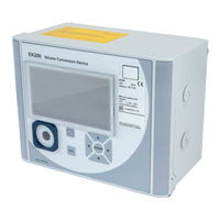
Honeywell Elster EK280 Operating Instructions Manual (110 pages)
Volume Conversion Device
Brand:
Honeywell
| Category:
Media Converter
| Size: 6.46 MB
Table of Contents
Table of Contents
3
1 General
7
Information about this Manual
7
Warranty Provisions
7
Customer Service and and Technical Support (TAC)
7
Customer Service and Repairs
8
Technical Assistance Center (TAC)
8
Meaning of Symbols
8
Safety Information
8
Tips and Recommendations
9
Limitationof Liability
9
Copyright Protection
10
Scope of Delivery
10
Spare Parts and Accessories
10
Storage
11
2 Safety
12
General
12
Intended Use
15
Personnel
16
Personal Protective Equipment
17
Specific Risks
18
Environmental Protection
19
Operator's Responsibility
19
3 Technical Data
20
General Data
20
Dimensions
21
Power Supply for EK280 Without Integrated Power Supply Unit
22
Battery Power Supply for the Basic Device
22
Battery Power Supply for the Integrated Modem
22
External Power Supply for the Basic Device
22
Power Supply for EK280 with Integrated Power Supply Unit
23
Battery Power Supply for the Basic Device
23
External Power Supply
23
Buffer Batteries for the Integrated Modem
23
Power Supply for the EK280 with Power over Ethernet (Poe)
23
Pressure Sensor
24
CT30 Type Pressure Sensor
24
Pressure Sensor Type 17002
25
Temperature Sensor
25
Digital Inputs
25
LF Pulse and Signal Inputs
25
HF Pulse Inputs (High Frequency)
26
Encoder Input
26
Digital Outputs
27
Nominal Data
27
LF Pulse or Signal Outputs
27
HF Pulse Outputs
27
Interfaces
28
Serial Optical Interface
28
Serial Electrical Interface
28
Integrated Modem
28
Ethernet Adapter
29
Measurement Conditions
29
Environment
29
Labelling
29
Type Label of the Volume Corrector
29
ATEX Marking
30
Device Software Identification
31
4 Construction and Function
32
External View
32
Internal View
32
Short Description
33
Connections
33
5 Assembly, Connection and Putting into Operation
34
Assembly
34
Assembly on a Gas Meter
35
Assembly on a Pipeline
35
Assembly on a Wall
36
Three-Way Valve
36
Connection
37
Connecting the Gas Meter
38
Sealing the Input Terminals
40
Connecting the Temperature Sensor
40
Connecting the Pressure Pipe
42
Connecting the Power Supply
43
Connect Outputs of the EK280
45
Earthing the EK280 Housing
46
Earthing the Cable Connections of the EK280
47
Additional Measures for Installation in Zone 2
47
Putting into Operation
48
Configuration of Measurement Parameters
48
Sealing
59
Closing the Housing
60
Verifying Assembly and Connection
61
Programming a Data Transfer
61
6 Operation
62
Safety
62
Personal Protective Equipment
62
Operating Personnel
62
Instructed Personnel
62
Qualified Personnel
62
Calibration Officers
63
Basic Principles
63
Display
64
Button Functions
65
Data Recall, Display Navigation
66
Meaning of Status Symbols
67
Error Messages When Entering Values
68
Access Rights
69
Data Register Content
72
Access Rights
72
Main" Register (Main Display)
72
Cust." Register (Customer)
74
Admin" Register (Administrator)
76
Serv." Register (Service)
77
Ctrl." Register (Control)
78
7 Maintenance
80
Safety
80
Personnel
82
Personal Protective Equipment
82
Environmental Protection
82
Testing and Changing Device Batteries
83
Changing and Connecting Device Batteries
83
Entering the Battery Capacity
85
Display Remaining Battery Power
86
8 Faults
87
Safety
87
Personnel
88
Personal Protective Equipment
88
Improper Elimination of Faults
88
Behaviour in the Event of Faults
89
Fault and Other Status Messages
89
9 Appendix
95
List of Spare Parts and Accessories
95
Fastening Elements
95
Pressure Connections
95
Temperature Sensor Pockets
95
Small Parts and Miscellaneous
96
Documentation
96
EC Declaration of Conformity
97
ATEX Type Examination Certificate
98
Zone 0, 1
98
Zone 2
106
Honeywell Elster EK280 Applications Manual (78 pages)
Brand:
Honeywell
| Category:
Measuring Instruments
| Size: 5.39 MB
Table of Contents
Table of Contents
3
1 General
5
Safety Instructions
5
Additional Information
5
2 EK280 Operation and Display
6
Display Configuration
6
Main" Main Display
6
Setting the Number of Tabs
6
User Values for the Customer
7
User Values for the Administrator
7
EK280 Archives Display
8
Progress Index
8
Search Function for Checking Archive Entries
9
Context Menu
10
Jump to Main Display ("Goto Main")
10
Freeze Display ("Freeze Display")
10
Clear Status Register ("Clear Status R.")
10
3 Working with Ensuite
11
Setting up the Communication Link to the EK280 Via Optical Interface
11
Setting up the Communication Link to EK280 Via a Modem
11
Setting up the Communication Link to EK280 Via a Network (TCP/IP)
11
Setting up a Direct Communication Link to EK280
12
Updating Customized Parameters
12
Send Parameter File
12
4 Volume Measurement
13
LF Pulse Generator (Reed Contact)
14
Connection
14
Parameterization
14
HF Pulse Generator (Namur)
15
Connection
15
Parameterization
15
Encoder
16
Connection
16
Parameterization
16
HF Pulse Input with Automatic Conversion
17
Pulse Generator Connection
17
Parameterization
18
Pulse Comparison
19
Pulse Generator Connection
19
Parameterization
20
5 Other Number and Status Inputs
21
Warning Input Active
21
Warning Input Inactive
22
Information Input Active
22
Information Input Inactive
23
Time-Synchronous Input
23
6 Data Transfer
24
Integrated GSM and GPRS Modem
24
SIM Card Insertion and Unlocking
24
GSM Operation
26
GPRS with TCP/IP
28
Replacing the Antenna
31
EM260 to Serial Interface
33
EM260 Connection
33
EM260 with Analog Modem (PSTN Modem)
33
EM260 with Ethernet Modem
35
FE260 to Serial Interface
37
FE260 Connection
37
FE260 SIM Card Insertion and Unlock
38
FE260 with Integrated Analog Modem (PSTN Modem)
40
FE260 GSM/GPRS Version, GSM Operating Mode
42
FE260 GSM/GPRS Version, GPRS with TCP/IP Operating Mode
44
FE260 GSM/GPRS Version with Comftp Modem Application
46
FE260 with Ethernet Modem
49
FE260 with RS232/RS485 Interface Card
51
Other Devices to Serial Interface
53
Direct RS232 Interface Connection (I.e. PC COM Port)
53
Ex Isolator MTL5051
56
RS485 Interface, Electrically Isolated
59
RS485 Interface, Without Electrical Isolation
61
Data Transfer Verification
63
GSM Modem Status "Stm
63
Connection Configuration Status "Stcon
63
Modbus
65
Default Settings
65
Formats
66
Value Readout Via Modbus
66
Value Update Via Modbus
66
Modbus Via RS232 Interface
67
Modbus Via Integrated Modem (Modbus RTU_TCP)
68
Archive Reading Via Modbus
69
7 Status Messages
70
Clearing Messages in the Status Register
70
List of Status Messages
71
8 Batteries
74
Device Battery Life
74
Standard Operation
74
Encoder for Volume Measurement
74
Additional Pressure or Temperature Sensors
75
Output Isolation (Galvanic Separation)
76
Modem Battery Life
77
Monthly Data Transfer
77
Weekly Data Transfer
77
Daily Data Transfer
77
Data Transfer Duration in Modem Battery Operation
78
Data Transfer Duration Depending on Ambient Temperature
78
Data Transfer Duration for Daily Call
78
Advertisement
Advertisement
Related Products
Honeywell EK205-M
Honeywell EkoFlush-K572
Honeywell EK205
Honeywell EDA50K-0
Honeywell INNCOM e7
Honeywell EW447A0100
Honeywell EC7820A1026/U
Honeywell Novar ES3.S
Honeywell E-Mon KWH/DEMAND
Honeywell E3 Point E3SA
Honeywell Categories
Thermostat
Controller
Control Unit
Security Camera
Accessories
More Honeywell Manuals
Login
Sign In
OR
Sign in with Facebook
Sign in with Google
Upload manual
Upload from disk
Upload from URL