Sign In
Upload
Manuals
Brands
Honeywell Manuals
Control Systems
Farenhyt IFP-300ECS
Honeywell Farenhyt IFP-300ECS Manuals
Manuals and User Guides for Honeywell Farenhyt IFP-300ECS. We have
3
Honeywell Farenhyt IFP-300ECS manuals available for free PDF download: Installation And Operation Manual, Manual
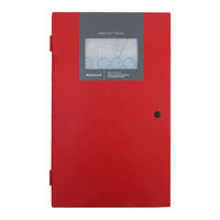
Honeywell Farenhyt IFP-300ECS Installation And Operation Manual (212 pages)
Addressable Fire Alarm Control System Emergency Communication system
Brand:
Honeywell
| Category:
Control Systems
| Size: 12.54 MB
Table of Contents
Table of Contents
5
Section 1: Introduction
11
Overview of Basic System
11
1: Hardware Features
11
2: Network System Hardware Features
11
3: Software Features
11
4: IFP-300ECS Features
11
5: Terms Used in this Manual
12
Compatible Products
12
Section 2: Agency Listings, Approvals, and Requirements
14
Federal Communications Commission (FCC)
14
Underwriters Laboratories (UL)
14
1: Requirements for All Installations
14
2: Requirements for Central Station Fire Alarm Systems
15
3: Requirements for Local Protected Fire Alarm Systems
15
4: Requirements for Remote Station Protected Fire Alarm Systems
15
5: Requirements for the Installation of Carbon Monoxide (CO) Detection and Warning Equipment, NFPA 720
15
6: NFPA Requirements
15
Section 3: before You Begin Installing
17
Inventory
17
Environmental Specifications
17
Software Downloads
17
Electrical Specifications
17
Wiring Specifications
18
Board Assembly Diagram
20
Calculating Current Draw and Standby Battery
20
1: Current Draw Worksheet Requirements
20
2: Current Draw Worksheet for IDP SLC Devices
21
3: Current Draw Worksheet for SK SLC Devices
24
4: Current Draw Worksheet SD for SLC Devices
28
5: Maximum Battery Standby Load
30
Section 4: Control Panel Installation
32
Mounting the Control Panel Cabinet
32
1: Preventing Water Damage
32
2: Removing the IFP-300/ECS Assembly from the Housing
32
3: Ethernet Connection
32
AC Connection
32
Battery Power
33
1: RBB Accessory Cabinet
34
Installing the RBB Accessory Cabinet and Batteries
34
SBUS Wiring
35
1: Calculating Wiring Distance for SBUS Modules
35
2: Wiring Configurations
37
RA-100 Remote Annunciator Installation
38
1: Mounting the RA-100
38
Flush Mounting
38
Surface Mounting
40
2: Connecting the RA-100 to the Panel
41
RA-1000 Remote Annunciator Installation
42
1: Mounting the RA-1000
42
Flush Mounting
43
2: Connecting the RA-1000 to the Panel
43
RA-2000 Remote Annunciator Installation
44
1: Mounting the RA-2000
44
Flush Mounting
44
Surface Mounting
46
2: RA-2000 Connection to the Panel
47
5815XL Installation
47
1: 5815XL Connection to the Panel
48
6815 Installation
48
1: 6815 Connection to the Panel
49
5824 Serial/Parallel Interface Module Installation
50
1: Selecting 5824 Options
50
5880 LED I/O Module
51
1: 5880 Board Layout
51
2: 5880 Connection to Panel
52
3: LED Wiring
52
4: Dry Contact Wiring
53
5865-3 / 5865-4 LED Annunciator Installation
53
1: 5865 Connection to Panel
54
2: 5865 Mounting
54
Configuring SBUS Modules
55
1: Assigning SBUS Module Ids
55
2: SBUS Bandwidth Considerations
56
Telephone Connection
57
Notification Appliance/Auxiliary Power Circuits
57
1: Conventional Notification Appliance
57
Class B Notification Wiring
57
Class a Notification Wiring
58
2: Auxiliary Power Installation
59
Door Holder Power
59
Constant Power
59
Resettable Power
59
Sounder Sync Power
59
On-Board Relays (Conventional)
60
1: Trouble Relay
60
2: Programmable Relays
60
Remote Station Applications
60
1: Keltron Model 3158 Installation
60
2: City Box Connection Using the 5220 Module
61
Using the Addressable Relay Module for City Box Connection
62
1: NFPA 72 Polarity Reversal
63
Using the 5220 Module
63
Using the 7644-L8 Module
63
2: Transmitter Activated by Dry Contacts
65
Section 5: Networking
66
Network System Hardware Features
66
1: Networked Sites
66
2: Wiring Options/Requirements to Connect Networked Panels
66
Network Wiring
66
NIC Wiring Options
67
1: Fiber Loop Modules
68
Accessory Mounting Kits
68
2: SK-NIC Installation
68
Unshielded Twisted Pair Wiring between Multiple Panels
70
Fiber Optic Multi-Mode Wiring between Multiple Panels
70
Fiber Optic and Twisted Pair Wiring between Multiple Panels
72
Setting the Network ID for each Panel
73
Section 6: Network Management
74
Network Diagnostics
74
1: Ping Panel
74
2: Data Network Status
74
3: Voice Network Status
74
Network Programming
74
1: Learn Network
74
2: Edit Network Names
74
3: Edit Panel ID
74
4: Computer Access
75
5: Access Codes
75
Edit Name
76
Edit Access Code
76
Panel Functions
76
6: Communicator Options
76
Communicator Assignments
77
Communicator Miscellaneous
77
Receiver Configuration
77
Communicator Reporting Table
77
Voice Options
77
1: Edit Timers
77
Control Lockout
78
Auto Reset ECS MIC Triggered Event
78
Sync Network Options
79
Network Management Quick Reference
80
Section 7: IDP, SK, SD and SWIFT™ SLC Device Installation
83
List of IDP SLC Devices
83
List of SK SLC Devices
84
List of SD SLC Devices
84
SWIFT™ Wireless SLC Devices
85
Maximum Number of Devices
85
Wiring Requirements for SD Devices
85
1: Wire Sizing on 5815XL for SD Devices
85
2: Wire Sizing for 6815
86
Wire Requirements for IDP or SK Modules
86
1: Wiring 5815XL or 6815 in Style 6 & 7 (Class A) Configuration
87
Addressing IDP or SK SLC Devices
88
Wiring SD Detectors
88
Addressing SD Devices
88
1: SLC Devices with DIP Switches
90
WIDP-WGI Wireless Gateway
90
1: Power Connections for the Gateway
91
Section 8: Programming Overview
92
Jumpstart® Autoprogramming
92
1: Input Points
92
2: Output Points
92
3: Running Jumpstart Autoprogramming
92
Mapping Overview
93
1: Input Point Mapping
94
2: Output Circuit Mapping
95
3: Event Mapping
95
4: Mapping LED Points
99
5: Mapping LED Points for a Networked System
100
Programming Using the HFSS Software Suite
100
Programming Using an Annunciator
100
1: Entering / Exiting the Panel Programming
100
2: Moving through the Menus
101
3: Selecting Options and Entering Data
101
Programming Menu Quick Reference
102
Section 9: Programming
113
UL 864 / UL 2572 Programming Requirements
113
Modules
113
1: Edit Modules
113
Editing Module ID
114
Naming Modules
114
Changing Module Options
114
2: Adding a Module
114
3: Deleting a Module
114
4: View Module List
114
Zone
115
1: Edit Zone
115
Edit Zone Name
115
Edit Zone Properties
115
Zone Accessory Options
117
2: View Zone Points
117
Group
117
1: Edit Group
117
Edit Group Name
117
Edit Group Properties
117
2: View Group Points
118
3: Edit OPG Template
118
Point
119
1: Point Programming for 5815XL Module
119
4: Point Programming for 5880 or 5865 Modules
125
5: Point Programming for 5496
126
6: Point Programming for ECS-AMP
127
7: Point Programming for ECS-VCM, ECS-NVCM and ECS-RVM Modules
127
System Options
129
1: Communication Options
129
Auto Test Time
129
Phone Lines
129
Edit Ethernet
131
Alarmnet Timers
131
Phone Line Gains
131
2: Daytime/Nighttime Sensitivity
132
3: Holiday Days
132
4: Time Options
133
Water Flow Delay
133
Alarm Verify
133
AC Report Delay
133
Change AC Line Frequency
133
Clock Display Format (AM/PM or Military)
133
Auto-Resound (4 or 24 Hours)
133
5: Miscellaneous Options
134
Strobes Active When Silenced
134
Auto Display Events
134
6: Daylight Saving Options
134
Automatic Daylight Saving Time Adjustment
134
Daylight Saving Time Start and End
134
7: Edit Banner
134
8: SLC Family
135
Jumpstart® Autoprogramming
135
Restore Defaults
135
Voice Options
135
1: VCM Maintenance
135
2: Voice Settings
136
Enable Dual Channel System
136
Section 10: System Operation
137
Default User and Installer Codes
137
Annunciator Description
137
1: LCD Display
137
2: Banner
138
3: Single Key Acknowledge
138
Menu System
138
1: Main Menu Overview
138
2: Using the Menus
139
Basic Operation
139
1: Setting Time and Date
139
2: Disable / Enable a Point
139
Disable / Enable Nacs by Template
139
Disable / Enable Nacs by Group
139
Disable / Enable Zone Points
139
Disable / Enable Point
139
Inhibit Output Group
139
3: View Event History
139
5: Conduct an Indicator Test
140
6: Conduct a Walk Test
140
7: Conduct a Communicator Test
140
8: Manual Alarmnet Registration
140
9: Silence Alarms or Troubles
141
10: Reset Alarms
141
Reset Communicator
141
11: Check Detector Sensitivity through Point Status
141
12: View Status of a Point
142
13: View Alarms or Troubles
142
14: System Information
142
Event Priority
143
1: System Control
143
2: System Override
143
4: Priority Rules
144
5: Other Priority Considerations
144
Operation Mode Behavior
144
1: Multi-Site Annunciator and Multi-Site User Access
147
Releasing Operations
147
2: Double Interlock Zone Releasing
149
Smoke Alarm Verification
150
Function Keys
150
1: Recording an F-Key Macro
151
2: Aborting an F-Key Macro Recording Session
151
3: Erasing an F-Key Macro
151
4: Using a Recorded F-Key Macro
151
5: F-Key Status Event
151
6: F-Key Map Inhibit
151
Section 11: Emergency Communication System Operation
152
Overview
152
LOC Functionality
152
1: Keys and Leds
152
ECS Control Key
152
ECS Control LED
152
ECS Message Keys
152
ECS Message Leds
152
Select Keys
152
Select Key Leds
153
2: Gaining ECS Control
153
LOC Priority
153
LOC Lockout
153
User Profile Access Control
154
3: Manual ECS
154
Switching between Microphone Mode and Message Mode
154
Activating/Deactivating Output Groups Dynamically
154
4: Microphone Mode
154
5: Message Mode
154
6: Custom ECS Event
154
7: Passing ECS Control
155
8: Exit ECS Control Menu
155
9: Relinquish ECS Control
155
10: ECS Reset
155
ECS Super User
155
ECS Point Functionality
156
1: ECS Point Activations
156
Amplifier Programming
156
1: Adding an Amplifier
156
2: Editing an Amplifier
156
LOC Programming
156
1: Adding an LOC
157
2: Editing an LOC
157
LOC Priority
157
LOC Association
157
Using the Microphone
157
1: Microphone Functionality
157
2: Custom ECS Event
157
3: Fire Page
157
Paging
158
Recording Custom Messages
158
2: Recording Messages 1-15 Using the Microphone
161
3: Erasing User Message
162
4: Using HFSS Voice Message Load Software
162
Network Paging
163
Priority
163
Configuration
163
Section 12: Reporting
164
Receivers Compatible with the Control Panel
164
SIA - Intelliknight / Panels PI Modifier Reporting
174
SIA - Panel Communicator
175
Section 13: Testing and Troubleshooting
177
Troubleshooting
177
Event History
177
Built-In Troubleshooting and Testing Tools
178
1: SLC Device Locator
178
2: SLC Multiple Device Locator
178
3: I/O Point Control
179
4: Earth Fault Resistance
179
Section 14: Installation Records
180
Detector and Module Point Record
180
Conventional Output Point Record
183
Appendix A: Compatible Devices
184
A.3: Notification Appliances
184
A.3.1: Two Wire Detectors
192
A.7: Compatible 520Hz Signaling Speakers
195
A.8: Compatible 520Hz Low Frequency Bases
195
Appendix B: Editing Text Using the Built-In Programmer
196
Appendix C: Expanded Receiver/Panel Relationship
197
Appendix D: Cadence Patterns
199
Panel Security
200
Honeywell Fire Product Warranty and Return Policy
201
Manufacturer Warranties and Limitation of Liability
202
Advertisement
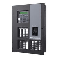
Honeywell Farenhyt IFP-300ECS Manual (176 pages)
Addressable Fire Alarm Control Panel
Brand:
Honeywell
| Category:
Fire Alarms
| Size: 2.89 MB
Table of Contents
Table of Contents
5
Section 1: Introduction
10
Basic System Overview
10
1: Hardware Features
10
2: Network System Hardware Features
10
3: Software Features
10
4: IFP-300ECS Features
10
5: Terms Used in this Manual
11
Compatible Products
11
Related Documentation
13
Section 2: Agency Listings, Approvals, and Requirements
14
Federal Communications Commission (FCC)
14
Underwriters Laboratories (UL)
14
1: Requirements for All Installations
14
2: UL 864 9Th and 10Th Edition
15
3: Requirements for Central Station Fire Alarm Systems
15
4: Requirements for Local Protected Fire Alarm Systems
15
5: Requirements for Remote Station Protected Fire Alarm Systems
15
6: Requirements for the Installation of Carbon Monoxide (CO) Detection and Warning Equipment, NFPA 720
15
7: NFPA Requirements
15
Section 3: Prerequisites for Installation
17
Inventory
17
Environmental Specifications
17
Software Downloads
17
Electrical Specifications
17
Calculating Current Draw and Standby Battery
18
1: Worksheet Requirements
18
2: Current Draw Worksheet for IDP SLC Devices
19
3: Current Draw Worksheet for SK SLC Devices
23
4: Current Draw Worksheet for SD SLC Devices
26
5: Maximum Battery Standby Load
29
Section 4: Control Panel Installation
30
Mounting the Control Panel Cabinet
30
1: Preventing Water Damage
30
2: Removing the IFP-300 Assembly from the Housing
30
3: Ethernet Connection
30
Board Layout
31
Wiring Specifications
31
AC Connection
33
Battery Power
33
1: RBB Accessory Cabinet
34
Wiring Specifications
35
1: Length Limitations
35
2: Calculating Wiring Distance for SBUS Modules
35
3: Wiring Configurations
37
RA-100 Remote Annunciator Installation
37
1: Mounting the RA-100
39
2: RA-100 Connection to the Panel
40
RA-1000 Remote Annunciator Installation
40
1: Mounting the RA-1000
41
RA-2000 Remote Annunciator Installation
43
1: Mounting the RA-2000
43
2: RA-2000 Connection to the Panel
45
5815XL Installation
45
1: 5815XL Connection to the Panel
46
6815 Installation
46
1: 6815 Connection to the Panel
47
5824 Serial/Parallel Printer Interface Module Installation
47
1: Selecting 5824 Options
48
5880 LED I/O Module
48
1: 5880 Board Layout
49
2: 5880 Connection to Panel
49
3: LED Wiring
49
4: Dry Contact Wiring
50
5865-3 / 5865-4 LED Annunciator Installation
51
1: 5865 Connection to Panel
51
2: 5865 Mounting
52
Configuring SBUS Modules
52
1: Assigning SBUS Module Ids
52
2: SBUS Bandwidth Considerations
53
Telephone Connection
53
Notification Appliance/Auxiliary Power Circuits
54
1: Conventional Notification Appliance
54
2: Auxiliary Power Installation
55
Onboard Relays (Conventional)
56
1: Trouble Relay
56
2: Programmable Relays
56
Remote Station Applications
56
1: Keltron Model 3158 Installation
56
2: City Box Connection Using the 5220 Module
57
3: Using the Addressable Relay Module for City Box Connection
58
4: NFPA 72 Polarity Reversal
59
5: Transmitter Activated by Dry Contacts
63
Section 5: Networking
64
Network System Hardware Features
64
1: Networked Sites
64
Network Wiring
64
1: Wiring Options/Requirements to Connect Networked Panels
64
NIC Wiring Options
65
1: Fiber Loop Modules
65
2: SK-NIC Mounting Kits
66
NIC Installation
66
1: SK-NIC Remote Mounting
67
2: Wiring
67
Setting the Network ID for each Panel
69
Section 6: Network Management
70
Network Diagnostics
70
1: Ping Panel
70
2: Data Network Status
70
3: Voice Network Status
70
Network Programming
70
1: Learn Network
70
2: Edit Network Names
70
3: Edit Panel ID
71
4: Computer Access
71
5: Access Codes
71
6: Communicator Options
72
Voice Options
73
1: Edit Timers
73
2: Edit Voice Commands
73
Sync Network Options
74
Network Management Quick Reference
75
Section 7: Programming Overview
77
Jumpstart Auto-Programming
77
1: Input Points
77
2: Output Points
77
3: Running Jumpstart Auto-Programming
77
Mapping Overview
78
1: Input Point Mapping
79
2: Output Circuit Mapping
79
3: Event Mapping
80
4: Mapping LED Points
82
5: Mapping LED Points for a Networked System
82
Programming Using the HFSS Software Suite
82
Programming Using an Annunciator
83
1: Entering / Exiting Panel Programming
83
2: Moving through the Menus
83
3: Selecting Options and Entering Data
83
Programming Menu Quick Reference
84
Section 8: Programming
95
UL 864 / UL 2572 Programming Requirements
95
Modules
95
1: Edit Modules
95
2: Adding a Module
96
3: Deleting a Module
96
4: View Module List
97
Zone
97
1: Edit Zone
97
2: View Zone Points
100
Group
100
1: Edit Group
100
2: View Group Points
101
3: Edit OPG (Output Group) Template
101
Point
101
1: Point Programming for a 5815XL Module
103
2: Point Programming for a 6815 Module
106
3: Point Programming for Internal or External Power Module (RPS-1000)
108
4: Point Programming for 5880 or 5865 Modules
110
5: Point Programming for the 5496
110
6: Point Programming for ECS Amplifiers
111
7: Point Programming for ECS-VCM, ECS-NVCM, and ECS-RVM Modules
111
System Options
111
1: Communication Options
111
2: Daytime/Nighttime Sensitivity
114
3: Holiday Days
114
4: Time Options
114
5: Miscellaneous Options
115
6: Daylight Savings Options
116
7: Edit Banner
116
8: SLC Family
117
Jumpstart Auto-Programming
117
Restore Defaults
117
Voice Options
117
1: VCM Maintenance
117
2: Voice Settings
117
Section 9: System Operation
119
Annunciator Description
119
1: LCD Display
119
2: Banner
119
Menu System
120
1: Panel Login Menu
120
2: Main Menu Overview
121
3: Using the Menus
121
Basic Operation
122
1: Setting Time and Date
122
2: Disable / Enable a Point
122
3: View Event History
122
4: Conduct a Fire Drill
122
5: Conduct an Indicator Test
123
6: Conduct a Walk Test
123
7: Conduct a Communicator Test
123
8: Manual Alarmnet Registration
123
9: Silence Alarms or Troubles
123
10: Reset Alarms
124
11: Check Detector Sensitivity through Point Status
124
12: View Status of a Point
125
13: View Alarms or Troubles
125
14: System Information
125
Event Priority
126
1: System Control
126
2: System Override
126
4: Priority Rules
127
5: Other Priority Considerations
127
Panel Operating Modes
127
1: Multi-Site Annunciator and Multi-Site User Access
130
Releasing Operations
130
1: Single Interlock Zone Releasing
131
2: Double Interlock Zone Releasing
131
Smoke Alarm Verification
132
Function Keys
132
1: Recording an F-Key Macro
132
2: Aborting an F-Key Macro Recording Session
132
3: Erasing an F-Key Macro
133
4: Using a Recorded F-Key Macro
133
5: F-Key Status Event
133
6: F-Key Map Inhibit
133
Section 10: Emergency Communication System Operation
134
Overview
134
LOC Functionality
134
1: Keys and Leds
134
2: Gaining ECS Control
135
3: Manual ECS
135
4: Fire
136
5: Message Mode
136
6: Custom ECS Event
137
7: Passing ECS Control
137
8: Exit ECS Control Menu
137
9: Relinquish ECS Control
137
10: ECS Reset
138
ECS Super User
138
ECS Point Functionality
138
1: ECS Point Activations
138
2: ECS-VCM, ECS-NVCM, and ECS-RVM Points
138
Amplifier Programming
138
1: Adding an Amplifier
138
2: Editing an Amplifier
139
LOC Programming
139
1: Adding an LOC
139
2: Editing an LOC
139
Using the Microphone
140
1: Microphone Functionality
140
2: Custom ECS Event
140
3: Fire Page
140
4: Emergency Page
140
5: Paging
140
Recording Custom Messages
141
1: Recording Messages 1-15 Using aux Audio Input
141
2: Recording Messages 1-15 Using the Microphone
142
3: Erasing User Messages
143
4: Using HFSS Voice Message Load Software
143
Network Paging
144
1: Priority
144
2: Configuration
144
Section 11: Reporting
145
Receivers Compatible with the Control Panel
145
SIA - Panels PI Modifier Reporting
154
SIA - Panel Communicator
154
Section 12: Testing and Troubleshooting
156
Troubleshooting
156
1: Common Problems
156
Periodic Testing and Maintenance
156
Event History
157
Built-In Troubleshooting and Testing Tools
157
1: SLC Device Locater
157
2: SLC Multiple Device Locater
157
3: I/O Point Control
158
4: Earth Fault Resistance
158
Section 13: Installation Records
159
Detector and Module Point Record
159
Additional SLC Devices
161
Conventional Output Point Record
162
Appendix A: Editing Text Using the Built-In Programmer
163
A.1: Characters Used for Editing Text
163
A.2: Example Name Edit
163
Appendix B: Expanded Receiver/Panel Relationship
164
Appendix C: Cadence Patterns
165
Appendix D: Panel Security
166
Model IFP-300 Basic Operating Instructions
167
Model IFP-300ECS Basic Operating Instructions
169
Keypad and LED Indicators
171
ECS Control
173
Honeywell Farenhyt IFP-300ECS Installation And Operation Manual (98 pages)
Emergency Communication System
Brand:
Honeywell
| Category:
Conference System
| Size: 2.72 MB
Table of Contents
Table of Contents
5
Overview
8
Optional Accessories
8
Features
9
Terms Used in this Manual
10
Agency Listings, Approvals, and Requirements
11
Federal Communications Commission (FCC)
11
Underwriters Laboratories (UL)
12
Requirements for All Installations
12
Requirements for Central Station Fire Alarm Systems
12
Requirements for Local Protected Fire Alarm Systems
12
Requirements for Remote Station Protected Fire Alarm Systems
13
Requirements for the Installation of Carbon Monoxide (CO) Detection and Warning Equipment, NFPA 720
13
Installation
14
Environmental Specifications
14
Wiring Specifications
14
Electrical Specifications
18
Installing ECS-Series Cabinets
18
Preventing Water Damage
18
Surface Mounting the IFP-100ECS, IFP-1000ECS, IFP-300ECS, IFP-2100ECS or ECS-LOC Cabinet
18
Surface Mounting the IFP-2000ECS or ECS-LOC Cabinet
19
Surface Mounting the IFP-300ECS Cabinet
21
Surface Mounting the IFP-2100ECS or ECS-LOC2100 Cabinet
22
Surface Mounting Instructions
22
Recessed Mounting Instructions
23
Cabinet Door and Dead Front Removal for IFP-100ECS, IFP-1000ECS and IFP-2000ECS
24
Cabinet Door and Dead Front Removal for IFP-300ECS and IFP-2100ECS
25
ECS Device Installation
26
Connecting AC Power and Batteries
26
Installing the ECS-VCM
26
ECS-VCM Board Layout
26
Connecting the ECS-VCM to the SBUS
27
Installing and Connecting the ECS-VCM to the ECS-SW24
28
Installing the Microphone
30
Installing the ECS-NVCM
31
ECS-NVCM Board Layout
32
Installing and Connecting the ECS-EMG to the ECS-SW24
33
ECS-NVCM Fiber Modules
36
Installing the Microphone
36
Installing the ECS-50W or ECS-50WB
38
ECS-50W Board Layout
38
Mounting the ECS-50W
39
Wiring Specifications
40
Speaker Wiring
41
Wiring Lengths
42
Class B Speaker Configuration
42
Class a Speaker Configuration
43
VBUS Wiring
43
SBUS Wiring
45
Connecting AC Power
46
Backup Battery for ECS-50W
48
Calculating Current Draw and Standby Battery
49
Installing the ECS-INT50W
49
Board Layout & Mounting
49
Mounting the ECS-INT50W
50
Wiring to a FACP
52
VBUS Wiring
52
Setting the Device Address
54
Speaker Wiring
54
Calculating Current Draw and Standby Battery
54
Installing the ECS-125W
55
ECS-125W Board Layout
55
Mounting the ECS-125W
56
Mounting the ECS-125WBD Board Only
56
Wiring Specifications
58
Speaker Wiring
60
Wiring Lengths
60
Class B
60
Class a
61
VBUS Wiring
61
SBUS Wiring
63
Connecting AC Power
65
Backup Battery for ECS-125W
65
Calculating Current Draw and Standby Battery
67
Installing the ECS-DUAL50W or ECS-DUAL-50WB
68
ECS-DUAL50W Board Layout
68
Mounting the ECS-DUAL50W
68
Mounting the ECS-DUAL50WBD Board Only
69
Wiring Specifications
70
Speaker Wiring
72
Wiring Lengths
72
Class B Speaker Configuration for ECS-Dual50W
72
Class a Speaker Configuration for ECS-Dual50W
73
VBUS Wiring
73
SBUS Wiring
76
Setting the ECS-DUAL50W Mode
79
Test Switch Use
79
Sw1 - Amp a
79
Sw2 - Amp B
79
Connecting AC Power
79
Backup Battery for ECS-DUAL50W
80
Calculating Current Draw and Standby Battery
81
Installing the ECS-50WBU
82
ECS-DUAL50W Board Layout
82
Installing the ECS-CE4
84
Installing the ECS-RVM
85
ECS-RVM Board Layout
85
Wiring the ECS-RVM
86
Installing the Microphone
87
To Remove the ECS-RVM
88
Addressing SBUS Devices
91
Panel Security
92
Honeywell Fire Product Warranty and Return Policy
94
Manufacturer Warranties and Limitation of Liability
95
Advertisement
Advertisement
Related Products
Honeywell Farenhyt Series
Honeywell IFP-300
Honeywell Farenhyt IFP-300B
Honeywell IFP-2100
Honeywell IFP-2100ECS
Honeywell Silent Knight IFP-2000 Module 3
Honeywell IFP1000
Honeywell IFP-1000ECS
Honeywell IFP-75
Honeywell IFP-75HV
Honeywell Categories
Thermostat
Controller
Control Unit
Security Camera
Accessories
More Honeywell Manuals
Login
Sign In
OR
Sign in with Facebook
Sign in with Google
Upload manual
Upload from disk
Upload from URL