
Related Manuals for Honeywell ECS Series


Summary of Contents for Honeywell ECS Series
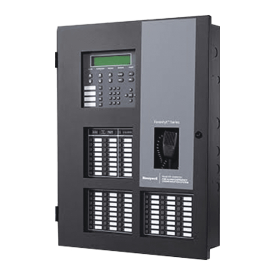
- Page 1 Installation and Operation Guide ECS-Series Emergency Communication System Document: 151455 Rev: ECN: 17-0212...
- Page 2 Fire Alarm & Emergency Communication System Limitations While a life safety system may lower insurance rates, it is not a substitute for life and property insurance! An automatic fire alarm system—typically made up of smoke sions (caused by escaping gas, improper storage of flammable detectors, heat detectors, manual pull stations, audible warning materials, etc.).
- Page 3 Installation Precautions Adherence to the following will aid in problem-free installation with long-term reliability: WARNING - Several different sources of power can be Like all solid state electronic devices, this system may connected to the fire alarm control panel. Disconnect all operate erratically or can be damaged when subjected to light- sources of power before servicing.
- Page 4 Documentation Feedback Your feedback helps us keep our documentation up-to-date and accurate. If you have a question or encounter a problem not covered in this manual, contact Honeywell Silent Knight Technical Support at 800-446-6444. Please give the following information: • Product name and version number (if applicable) •...
-
Page 5: Table Of Contents
Contents Section 1 Overview ..............................1-1 Optional Accessories ........................1-1 Features ...........................1-2 Terms Used in this Manual .......................1-3 Section 2 Agency Listings, Approvals, and Requirements ........2-1 Federal Communications Commission (FCC) ................2-1 Underwriters Laboratories (UL) ....................2-2 2.2.1 Requirements for All Installations ..................2-2 2.2.2 Requirements for Central Station Fire Alarm Systems ............2-2 2.2.3 Requirements for Local Protected Fire Alarm Systems .............2-2 2.2.4 Requirements for Remote Station Protected Fire Alarm Systems ........2-3... - Page 6 4.2.2 Connecting the ECS-VCM to the SBUS ................4-2 4.2.3 Installing and Connecting the ECS-VCM to the ECS-SW24 ..........4-3 4.2.4 Installing the Microphone ....................4-5 Installing the ECS-NVCM ......................4-6 4.3.1 ECS-NVCM Board Layout ....................4-7 4.3.2 Installing and Connecting the ECS-EMG to the ECS-SW24 ..........4-8 4.3.3 ECS-NVCM Fiber Modules ....................4-11 4.3.4 Installing the Microphone ....................4-11 Installing the ECS-50W or ECS-50WB ...................4-13...
- Page 7 4.11.1 ECS-RVM Board Layout ....................4-60 4.11.2 Wiring the ECS-RVM ......................4-61 4.11.3 Installing the Microphone ....................4-62 4.11.4 To Remove the ECS-RVM .....................4-63 4.12 Addressing SBUS Devices .....................4-66 Panel Security Honeywell Fire Product Warranty and Return Policy Manufacturer Warranties and Limitation of Liability...
-
Page 8: Overview
ECS-RVM (Remote Voice Module) ECS-LOC2100 RA-2000 (Remote Annunciator) Optional Accessories This manual also contains information on how to install the following compatible accessory with the ECS series equipment: Model Number Description Compatible With ECS-SW24 Adds 24 additional switches to the ECS-VCM, ECS-NVCM... -
Page 9: Features
ECS Series Emergency Communication System Installation Manual 151455 Model Number Description Compatible With ECS-RVM Remote Voice Module IFP-100ECS, IFP-1000ECS, IFP-2000ECS, IFP-300ECS, and IFP-2100ECS ECS-LOC Local Operating Console IFP-100ECS, IFP-300ECS, IFP- 1000ECS, and IFP-2000ECS ECS-LOC2100 Local Operating Console IFP-2100ECS ECS-DUAL50W / ECS-... -
Page 10: Terms Used In This Manual
FACP Fire Alarm Control Panel. Local Operator's Console. The user interface for a Mass Notification System. In the Honeywell Farenhyt Series product line, this would be the interface provided by the IFP- 100ECS, IFP-1000ECS, IFP-300ECS, IFP-2000ECS, or IFP-2100ECS Mass Notification A way of protecting life by relaying specific event information to a building or site including voice and/or audible and visual signals. -
Page 11: Agency Listings, Approvals, And Requirements
Agency Listings, Approvals, and Requirements Federal Communications Commission (FCC) 1. The following information must be provided to the telephone company before the FACP can be connected to the phone lines: Manufacturer: Honeywell Silent Knight Model Number: IFP-100ECS, IFP-1000ECS, IFP-2000ECS, IFP-300ECS, IFP-2100ECS FCC registration number:... -
Page 12: Underwriters Laboratories (Ul)
ECS Series Emergency Communication System Installation Manual 151455 Underwriters Laboratories (UL) 2.2.1 Requirements for All Installations General requirements are described in this section. When installing an individual device, refer to the specific section of the manual for additional requirements. The following subsections list specific requirements for each type of installation (for example, Central Station Fire Alarm systems, Local Protected Fire Alarm systems, and so on). -
Page 13: Requirements For Remote Station Protected Fire Alarm Systems
Requirements for Remote Station Protected Fire Alarm Systems Minimum system requirements are one Honeywell Silent Knight addressable initiating device and either a 5220, Keltron 3158 or the built-in Digital Alarm Communicator Transmitter (DACT). Do not exceed the current load restrictions shown in Section 3.7.5. -
Page 14: Installation
151455 Section 3 Installation This section of the manual is intended to help you plan your tasks to complete the installation. Please read this section thoroughly, especially if you are installing a ECS-Series control for the first time. Environmental Specifications It is important to protect the ECS panel from water. - Page 15 ECS Series Emergency Communication System Installation Manual 151455 be reduced by running the wire through ferrite shield beads or by wrapping it around a ferrite toroid. Telco Wiring SLC Devices Relays NACs VBUS SBUS Devices IFP-100ECS Flexputs / NACs Devices...
- Page 16 Installation 151455 and low voltage circuits and between power-limited and non-power limited circuits. Relays AC Power Input Flexputs / NACS Device VBUS SBUS Devices Figure 3-2 IFP-2000ECS Wire Routing Example AC Power Input SBUS devices devices Phone Lines Figure 3-3 Wire Routing IFP-300ECS...
- Page 17 ECS Series Emergency Communication System Installation Manual 151455 Relay To Phone AC Power outputs Input lines devices SBUS devices Figure 3-4 Wire Routing IFP-2100ECS...
-
Page 18: Electrical Specifications
200 mA 1310 mA Fully loaded system Installing ECS-Series Cabinets This section provides instructions on how to install the ECS series cabinets for surface or flush mounting. 3.4.1 Preventing Water Damage Refer to Section 3.1 when choosing a mounting location. Water damage to the fire system can be caused by moisture entering the cabinet through the conduits. -
Page 19: Surface Mounting The Ifp-2000Ecs Or Ecs-Loc Cabinet
ECS Series Emergency Communication System Installation Manual 151455 For more information, refer to FACP Installation manuals. Model Number FACP Installation Manual PN IFP-2000ECS 151430-L8 IFP-1000ECS 151460 IFP-100ECS 151458 IFP-300ECS LS10145-001SK-E IFP-2100ECS LS10143-001SK-E Cabinet backbox dimensions are 20" W x 26.5” H x 4.82" D. - Page 20 Installation 151455 Key Shaped Holes 27" Bottom Mounting Holes 20.362" Figure 3-6 IFP-2000ECS and ECS-LOC Cabinet Mounting Holes...
-
Page 21: Surface Mounting The Ifp-300Ecs Cabinet
ECS Series Emergency Communication System Installation Manual 151455 3.4.4 Surface Mounting the IFP-300ECS Cabinet The Cabinets can be mounted on the wall surface by using the mounting holes in the back of the cabinet (see Figure 3-6). For more information, refer to Installation manuals for IFP-300ECS (PN LS10145-001SK-E). -
Page 22: Surface Mounting The Ifp-2100Ecs Or Ecs-Loc2100 Cabinet
Installation 151455 3.4.5 Surface Mounting the IFP-2100ECS or ECS-LOC2100 Cabi- The ECS-LOC2100 is a combination ECS-RVM Remote Voice Module and its associated RA-2000 annunciator. The ECS-LOC2100 is compatible with the IFP-2100ECS. The Cabinets can be mounted on the wall surface by using the mounting holes in the back of the cabinet (see Figure 3-8). -
Page 23: Recessed Mounting Instructions
ECS Series Emergency Communication System Installation Manual 151455 3.4.7 Recessed Mounting Instructions This section describes how to recess mount the cabinet IFP-100ECS, IFP-1000ECS or IFP-2000ECS into a wall. To recess mount the cabinet you will need to have the optional trim ring P/N VIP-TR (ordered separately). -
Page 24: Cabinet Door And Dead Front Removal For Ifp-100Ecs, Ifp-1000Ecs And Ifp-2000Ecs
Installation 151455 4. Place the trim ring around the cabinet. See Figure 3-10. Trim Ring Cabinet Figure 3-10 Trim Ring Around cabinet 5. Secure the trim ring to the cabinet using the self-tapping sheet metal screws from the inside of the cabinet into the trim ring. -
Page 25: Cabinet Door And Dead Front Removal For Ifp-300Ecs And Ifp-2100Ecs
ECS Series Emergency Communication System Installation Manual 151455 Re-Attaching the Cabinet Door To re-attach the cabinet door reverse the procedure in section 3.4.7.1. 3.4.7.2 Cabinet Door and Dead Front Removal for IFP-300ECS and IFP-2100ECS While installing the cabinet it may be necessary to remove the cabinet door and the dead front panel. -
Page 26: Ecs Device Installation
LS10143-001SK-E Installing the ECS-VCM The ECS-VCM Voice Control Module is contained within the Honeywell Farenhyt Series ECS panel enclosure. It provides a supervised microphone for live communication and an interface for the Emergency Communication System. This section provides information on how to install or remove the ECS-VCM to the control cabinet and how to make the proper wiring connections. -
Page 27: Connecting The Ecs-Vcm To The Sbus
ECS Series Emergency Communication System Installation Manual 151455 Figure 4-2 Front View of ECS-VCM 4.2.2 Connecting the ECS-VCM to the SBUS Refer to Figure 4-3 to properly connect the ECS-VCM to the FACPs SBUS. ECS-VCM Supervised Power Limited FACP Figure 4-3 SBUS Connections... -
Page 28: Installing And Connecting The Ecs-Vcm To The Ecs-Sw24
ECS Device Installation 151455 4.2.3 Installing and Connecting the ECS-VCM to the ECS-SW24 The ECS-SW24 adds 24 switches to the IFP-100ECS, IFP-1000ECS, ECS-LOC, IFP-2000ECS controls for a total of 40 (with the 16 Non-ECS switches on the ECS-VCM). Follow these steps to install and connect the ECS-SW24: 1. - Page 29 ECS Series Emergency Communication System Installation Manual 151455 Figure 4-5 Wiring Harness Connection for VCM to Two ECS-SW24 Mounting Studs ECS-SW24 Figure 4-6 Back View of IFP-100ECS or IFP-1000ECS Dead Front Panel...
-
Page 30: Installing The Microphone
ECS Device Installation 151455 Mounting Studs ECS-SW24 Figure 4-7 Back View of IFP-2000ECS Dead Front Panel 4.2.4 Installing the Microphone To install the microphone follow these steps: 1. Clip the microphone into the micro phone clip. See Figure 4-18. Figure 4-8 Sliding Microphone into Microphone Clip 2. -
Page 31: Installing The Ecs-Nvcm
ECS Series Emergency Communication System Installation Manual 151455 Figure 4-19. Figure 4-9 Microphone Cord Inserted Through Dead Front Panel Hole 3. Attach strain relief clip to microphone cord. The strain relief clip should have about 2-3/4” of micro phone cord through it. See Figure 4-20. -
Page 32: Ecs-Nvcm Board Layout
ECS Device Installation 151455 4.3.1 ECS-NVCM Board Layout Network Connector Keypad connector AUX AUDIO VBUS1 CMD1 COMMON Fiber CMD2 Module Connectors Port 2 VBUS2 Port 1 Figure 4-11 Front View of ECS-NVCM Microphone ECS-NVCM Connection Connector ECS-SW24 Connector Figure 4-12 Back View of ECS-EMG Keypad... -
Page 33: Installing And Connecting The Ecs-Emg To The Ecs-Sw24
ECS Series Emergency Communication System Installation Manual 151455 ECS-EMG ECS-NVCM Figure 4-13 ECS-NVCM with ECS-EMG Location for IFP-2100ECS 4.3.2 Installing and Connecting the ECS-EMG to the ECS-SW24 The ECS-SW24 adds 24 switches to the IFP-300ECS and IFP-2100ECS controls for a total of 40. - Page 34 ECS Device Installation 151455 9. Reconnect backup batteries FACP NVCM Figure 4-14 Wiring Harness Connection for NVCM to IFP-300ECS Figure 4-15 Connection between ECS-EMG and One ECS-SW24...
- Page 35 ECS Series Emergency Communication System Installation Manual 151455 Figure 4-16 Wiring Harness Connection for NVCM to IFP-2100ECS Figure 4-17 Connection between ECS-EMG and Two ECS-SW24s 4-10...
-
Page 36: Ecs-Nvcm Fiber Modules
ECS Device Installation 151455 4.3.3 ECS-NVCM Fiber Modules The ECS-NVCM supports two types of fiber-option modules to convert wire to fiber. For more information see Installation sheet PN LS10178-001SK-E. • SK-FML (Fiber-Optic Multi-Mode, Receiver) • SK-FSL (Fiber-Optic Single-Mode, Transmitter) 4.3.4 Installing the Microphone To install the microphone follow these steps: 1. - Page 37 ECS Series Emergency Communication System Installation Manual 151455 Figure 4-19. Figure 4-19 Microphone Cord Inserted Through Dead Front Panel Hole 3. Attach strain relief clip to microphone cord. The strain relief clip should have about 2¾” of micro phone cord through it. See Figure 4-20.
-
Page 38: Installing The Ecs-50W Or Ecs-50Wb
ECS Device Installation 151455 Installing the ECS-50W or ECS-50WB This section provides information on how to install the ECS-50W for use with the ECS-Series products. ECS-50W is also available in a black cabinet as P/N ECS-50WB 4.4.1 ECS-50W Board Layout Figure 4-21 shows the location of terminals, DIPs, and Expander connection, used in the installation of the ECS-50W. -
Page 39: Mounting The Ecs-50W
ECS Series Emergency Communication System Installation Manual 151455 4.4.2 Mounting the ECS-50W The ECS-50W is equipped with a separate enclosure. It is also available in a black cabinet. (P/N ECS- 50WB). Refer to Section 3.1 when selecting a mounting location for the ECS-50W. -
Page 40: Wiring Specifications
ECS Device Installation 151455 4.4.3 Wiring Specifications All wiring and devices installed in the system must meet the standards described in National Electrical Code (NFPA 70), NFPA Standard 72, and Life Safety Code (NFPA 101). To avoid induced noise (transfer of electrical energy from one wire to another), keep input wiring isolated from high-current output and power wiring. -
Page 41: Speaker Wiring
ECS Series Emergency Communication System Installation Manual 151455 Figure 4-23 provides an example. Figure 4-23 Wire Routing Example for ECS-50W 4.4.4 Speaker Wiring Each ECS-50W supplies four NAC (Notification Appliance Circuit) for speaker connection. The speaker circuit can be supervised and wired Class B (Style Y) or Class A (Style Z). The speaker circuit is capable of 50 watts of power at 25 Vrms or 70.7 Vrms. -
Page 42: Wiring Lengths
ECS Device Installation 151455 4.4.4.1 Wiring Lengths Table 4-2 Number Of Speakers Total Load Wire Distance in Feet @1/2 W @1 W Vrms Watts 18 AWG 16 AWG 14 AWG 12 AWG 25Vrms 3900 6200 9860 15680 70Vrms 25000 39700 63200 100520 25Vrms... -
Page 43: Class A Speaker Configuration
ECS Series Emergency Communication System Installation Manual 151455 4.4.4.3 Class A Speaker Configuration Figure 4-25 illustrates how to wire speakers to the control panel using Class A wiring. Supervised Power Limited Figure 4-25 Class A Speaker Configuration 4.4.5 VBUS Wiring The VBUS is an analog voice bus that carries the recorded voice messages from the ECS-VCM or ECS-NVCM to the ECS-50W’s, or the voice messages generated from a system microphone to the... - Page 44 ECS Device Installation 151455 ECS-NVCM VBUS Connections 3 Vrms, 5mA max. Supervised Power Limited 15kΩ EOL at last panel on the VBUS ECS-50W ECS-50W Figure 4-27 VBUS Wiring with ECS-NVCM 4-19...
-
Page 45: Sbus Wiring
ECS Series Emergency Communication System Installation Manual 151455 4.4.6 SBUS Wiring This section contains information on how to connect ECS-50Ws (up to 8 for IFP-100ECS, IFP-300ECS or IFP-1000ECS or up to 16 for IFP-2000ECS or IFP-2100ECS) onto the main control SBUS. Refer to Section 4.1 for SBUS specifications. -
Page 46: Connecting Ac Power
ECS Device Installation 151455 4.4.7 Connecting AC Power The AC inputs are rated as 120 VAC, 60 Hz (transformer P/N 115061). To install the AC transformer into the ECS-50W cabinet follow these steps: 1. Open the cabinet door. 2. To access cabinet interior, open dead-front panel by removing the upper screw and the mid-door retaining screw. - Page 47 ECS Series Emergency Communication System Installation Manual 151455 4. Connect AC to the Transformer as Shown in Figure 4-31. Figure 4-31 AC Connections 5. Plug the transformer output to the AC connector on the control panel as shown in Figure 4-31.
-
Page 48: Backup Battery For Ecs-50W
ECS Device Installation 151455 4.4.8 Backup Battery for ECS-50W The following steps explain how to connect the batteries (refer to Figure 4-32): 1. Connect the black wire of the battery harness to the (-) side of the battery #2. 2. Connect the jumper wire provided form the positive (+) side of battery #2 to the negative side of battery #1. -
Page 49: Calculating Current Draw And Standby Battery
ECS Series Emergency Communication System Installation Manual 151455 4.4.9 Calculating Current Draw and Standby Battery This section helps you determine the current draw and standby battery needs for your installation (18 Ampere Hours max. will fit in cabinet). Complete the remaining instructions in Table 4-3. -
Page 50: Mounting The Ecs-Int50W
ECS Device Installation 151455 4.5.1.1 Mounting the ECS-INT50W 1. Remove AC power and disconnect the backup batteries from the main control panel. 2. To mount the ECS-INT50W inside the FACP cabinet under the main board, align the board with the mounting holes. Secure the board to the enclosure with the supplied screws. See Figure 4-34. Figure 4-34 ECS-INT50W in FACP Cabinet 3. - Page 51 ECS Series Emergency Communication System Installation Manual 151455 Figure 4-36 ECS-INT50W Installed using the ECS-AMPMT Install with coils to the top, right Figure 4-37 ECS-INT50W installed in IFP-2100ECS Cabinet 4-26...
-
Page 52: Wiring To A Facp
ECS Device Installation 151455 4.5.2 Wiring to a FACP See Figure 4-38 to properly wire the ECS-INT50W to the FACP. The Internal Amplifier must be powered by a NAC programmed as Constant Auxiliary Power. Refer to the FACP installation manual. ECS-INT50W FACP Figure 4-38 Wiring the ECS-INT50W to the FACP... - Page 53 ECS Series Emergency Communication System Installation Manual 151455 Connect the VBUS from the ECS-VCM to the ECS-INT50Ws as shown in Figure 4-39. ECS-VCM ECS-INT50W ECS-INT50W Figure 4-39 : VBUS Wiring for ECS-VCM ECS-NVCM ECS-INT50W ECS-INT50W Figure 4-40 : VBUS Wiring for ECS-NVCM...
-
Page 54: Setting The Device Address
ECS Device Installation 151455 4.5.4 Setting the Device Address Use the on-board DIP switches to select an ID number for the ECS-INT50W. Refer to Figure 4-88 to set the DIP switches for the desired ID number. Once the ID number is set, you must add the ECS-INT50W to the system through programming. Note: ECS-INT50W is powered by a NAC. -
Page 55: Installing The Ecs-125W
ECS Series Emergency Communication System Installation Manual 151455 Installing the ECS-125W This section provides information on how to install the ECS-125W for use with ECS-series products. 4.7.1 ECS-125W Board Layout Figure 4-41 shows the location of terminals, DIPs, and Expander connections used in the installation of the ECS-125W. -
Page 56: Mounting The Ecs-125W
ECS Device Installation 151455 4.7.2 Mounting the ECS-125W The ECS-125W is equipped with a separate enclosure. Refer to Section 3.1 when selecting a mounting location for the ECS-125W. The panel should be accessible to main drop wiring runs. It should be mounted as close to the center of the building as possible and located within a secured area, but should be accessible for testing and service. - Page 57 ECS Series Emergency Communication System Installation Manual 151455 3. Secure the supplied bracket to the top mounting bracket on the ECS-125WBD with the two mount- ing screws. See Figure 4-43. Figure 4-43 : ECS-125WBD Mounting Bracket 4. Align the mounting holes on the bracket with the enclosure.
-
Page 58: Wiring Specifications
ECS Device Installation 151455 4.7.4 Wiring Specifications All wiring and devices installed in the system must meet the standards described in National Electrical Code (NFPA 70), NFPA Standard 72, and Life Safety Code (NFPA 101). To avoid induced noise (transfer of electrical energy from one wire to another), keep input wiring isolated from high-current output and power wiring. - Page 59 ECS Series Emergency Communication System Installation Manual 151455 Figure 4-45 provides an example. To AC VBUS In & Out SBUS Audio Circuits ECS-CE4 Audio Circuits Audio Circuits Battery Connection Figure 4-45 Wire Routing Example for ECS-125W 4-34...
-
Page 60: Speaker Wiring
ECS Device Installation 151455 4.7.5 Speaker Wiring Each ECS-125W supplies four NAC (Notification Appliance Circuit) for speaker connection. The speaker circuit can be supervised and wired Class B or Class A. Speaker circuit 1 is capable of 100 watts of power at 25 Vrms. Speaker circuit 2-4 are capable of 50 watts (each) at 25 Vrms. 4.7.5.1 Wiring Lengths Table 4-5 Wire Lengths Number Of Speakers... -
Page 61: Class A
ECS Series Emergency Communication System Installation Manual 151455 4.7.5.3 Class A Figure 4-47 illustrates how to wire speakers to the control panel using Class A wiring. Supervised Power Limited Figure 4-47 Class A Speaker Configuration 4.7.6 VBUS Wiring The VBUS is an analog voice bus that carries the recorded voice messages from the ECS-VCM or ECS-NVCM to the ECS-125Ws, or the voice messages generated from a system microphone to the ECS-125Ws. - Page 62 ECS Device Installation 151455 15kΩ EOL at Last panel ECS-125W on the VBUS Supervised Power Limited ECS-125W ECS-NVCM Figure 4-49 VBUS Wiring for ECS-NVCM 4-37...
-
Page 63: Sbus Wiring
ECS Series Emergency Communication System Installation Manual 151455 4.7.7 SBUS Wiring This section contains information on how to connect ECS-125Ws (up to 8 for IFP-100ECS, IFP- 300ECS, or IFP-1000ECS. Up to 16 for IFP-2000ECS or IFP-2100ECS) onto the main control SBUS. - Page 64 ECS Device Installation 151455 ECS-VCM Supervised Power Limited ECS-125W ECS-125W To next ECS-125W (Max 8) Figure 4-51 Connecting Multiple ECS-125Ws to the SBUS using ECS-VCM Figure 4-52 Connecting ECS-125W to the SBUS using ECS-NVCM 4-39...
-
Page 65: Connecting Ac Power
ECS Series Emergency Communication System Installation Manual 151455 Figure 4-53 Connecting Multiple ECS-125Ws to the SBUS using ECS-NVCM See Section 4.12 for information on setting SBUS addresses. 4.7.8 Connecting AC Power At installation, connect the AC terminals to the power source as shown in Figure 4-54. It may be necessary for a professional electrician to make this connection. - Page 66 ECS Device Installation 151455 1. Connect the black wire of the battery harness to the (-) side of the battery #2. 2. Connect the jumper wire provided form the positive (+) side of battery #2 to the negative side of battery #1.
-
Page 67: Calculating Current Draw And Standby Battery
ECS Series Emergency Communication System Installation Manual 151455 4.7.10 Calculating Current Draw and Standby Battery This section helps you determine the current draw and standby battery needs for your installation (18 Ampere Hours maximum will fit in cabinet). Complete the remaining instructions in Table 4-6. -
Page 68: Installing The Ecs-Dual50W Or Ecs-Dual-50Wb
ECS Device Installation 151455 Installing the ECS-DUAL50W or ECS-DUAL-50WB This section provides information on how to install the ECS-DUAL50W for use with the IFP-2100ECS, IFP-2000ECS, IFP-1000ECS, IFP-300ECS and IFP-100ECS. ECS-DUAL50W is available in a black cabinet as P/N ECS-DUAL50WB.* 4.8.1 ECS-DUAL50W Board Layout Figure 4-56 shows the location of terminals, DIP switch’s and Expander connection used in the installation of the ECS-DUAL50W. -
Page 69: Mounting The Ecs-Dual50Wbd Board Only
ECS Series Emergency Communication System Installation Manual 151455 The cabinet can be surface or flush-mounted. If you will be flush-mounting the cabinet, the hole for the enclosure should be 14.5" W x 24.75" H x 3-7/16” D (36.8cm W x 62.9cm H x 8.73cm D). Do not flush- mount in a wall designated as a fire break. -
Page 70: Wiring Specifications
ECS Device Installation 151455 mounting screws. See Figure 4-58. Figure 4-58 : ECS-DUAL50WBD Mounting Bracket 4. Align the mounting holes on the bracket with the enclosure. 5. Secure the board to the enclosure. 6. Restore AC power and reconnect the backup batteries. Mounting Bracket Figure 4-59 : ECS-DUAL50WBD In Enclosure... - Page 71 ECS Series Emergency Communication System Installation Manual 151455 Instead, separate the wiring as follows: 1/4” spacing must be maintained Input/Output Type: Wiring between each of these circuit types; Non Power-Limited: AC power, Standby batteries as well as between power limited...
-
Page 72: Speaker Wiring
ECS Device Installation 151455 4.8.5 Speaker Wiring Each ECS-DUAL50W supplies eight NAC (Notification Appliance Circuit) for speaker connection. The speaker circuit can be supervised and wired Class B or Class A. The speaker circuits are capable of 50 watts (each) at 25 Vrms or 70.7 Vrms. 4.8.5.1 Wiring Lengths Table 4-7: Wire Lengths for ECS-DUAL50W Number Of Speakers... -
Page 73: Class A Speaker Configuration For Ecs-Dual50W
ECS Series Emergency Communication System Installation Manual 151455 4.8.5.3 Class A Speaker Configuration for ECS-Dual50W Figure 4-62 illustrates how to wire speakers to the control panel using Class A wiring. Supervised Power Limited Figure 4-62 Class A Speaker Configuration 4.8.6... - Page 74 ECS Device Installation 151455 64 for ECS-VCM or Figure 4-65 and Figure 4-66 for ECS-NVCM.. ECS-VCM To next ECS-DUAL50W ECS-DUAL50W Supervised Power Limited UL Listed 15kΩ EOL at Last panel on the VBUS ECS-DUAL50W Figure 4-63 VBUS Wiring for Single Channel for ECS-VCM 4-49...
- Page 75 ECS Series Emergency Communication System Installation Manual 151455 ECS-VCM To next ECS-DUAL50W ECS-DUAL50W Supervised Power Limited Ω UL Listed 15k EOL at Last panel on the VBUS ECS-DUAL50W Figure 4-64 VBUS2 Wiring for Dual Channel for ECS-VCM Figure 4-65 VBUS Wiring for Single Channel for ECS-NVCM...
-
Page 76: Sbus Wiring
ECS Device Installation 151455 ECS-DUAL50W ECS-DUAL50W ECS-NVCM Figure 4-66 VBUS2 Wiring for Dual Channel for ECS-NVCM 4.8.7 SBUS Wiring This section contains information on how to connect ECS-DUAL50Ws (up to 8 for IFP-100ECS, IFP- 300ECS, IFP-1000ECS or up to 16 for IFP-2000ECS or IFP-2100ECS) onto the main control SBUS. Refer to Section 4 of the FACPs Installation manual for SBUS specifications. - Page 77 ECS Series Emergency Communication System Installation Manual 151455 ECS-VCM Supervised Power Limited ECS-DUAL50W ECS-DUAL50W To next ECS-DUAL50W (Max 8) Figure 4-68 Connecting Multiple ECS-DUAL50Ws to the SBUS using ECS-VCM 4-52...
- Page 78 ECS Device Installation 151455 FACP Figure 4-69 SBUS Connections to the ECS-DUAL50W FACP To next ECS-DUAL50W Figure 4-70 SBUS Connections to Multi ECS-DUAL50Ws See Section 4.12 for information on setting SBUS addresses. 4-53...
-
Page 79: Setting The Ecs-Dual50W Mode
ECS Series Emergency Communication System Installation Manual 151455 4.8.8 Setting the ECS-DUAL50W Mode Figure 4-71 DIP Switch Modes When the ECS-DUAL50W is connected to an IFP-100ECS or IFP-1000ECS version 13 or prior, see Figure 4-71 to set the amplifier mode. Version 14 or later, the mode is set using the SKSS, Silent Knight Software Suite and the DIP switch mode selector is ignored. -
Page 80: Backup Battery For Ecs-Dual50W
ECS Device Installation 151455 The AC terminals are rated as 120 VAC, 60 Hz or 240 VAC, 50 Hz. Figure 4-72 AC Connection 4.8.11 Backup Battery for ECS-DUAL50W The following steps explain how to connect the batteries (refer to Figure 4-78): 1. -
Page 81: Calculating Current Draw And Standby Battery
ECS Series Emergency Communication System Installation Manual 151455 4.8.12 Calculating Current Draw and Standby Battery This section helps you determine the current draw and standby battery needs for your installation (18 Ampere Hours maximum will fit in cabinet). Complete the remaining instructions in Table 4-8. -
Page 82: Installing The Ecs-50Wbu
ECS Device Installation 151455 Installing the ECS-50WBU The ECS-50WBU provides backup capability when operating the ECS-DUAL50W in the 100 watt with backup mode for both single and dual channel setups. The ECS-50WBU mounts above the ECS-DUAL50W board on the standoffs provided. 4.9.1 ECS-DUAL50W Board Layout Figure 4-74 shows the location of the ECS-50WBU on the ECS-DUAL50W board. - Page 83 ECS Series Emergency Communication System Installation Manual 151455 4.9.2 Installing the ECS-50WBU Follow these steps to install the ECS-50WBU. 1. Make sure that all power supplied to the ECS-DUAL50W is removed. 2. Connect the backup amplifier cable harness (P/N 50116775-001) from the connector labeled “Backup Amplifier”...
-
Page 84: Installing The Ecs-Ce4
ECS Device Installation 151455 4.10 Installing the ECS-CE4 The ECS-CE4 adds four audio circuits to the ECS-50W and ECS-125W. The ECS-CE4 mounts inside the ECS-50W or ECS-125W cabinet. Follow these steps to install the ECS-CE4. 1. Using the four supplied screws mount the ECS-CE4 in the cabinet as shown in Figure 4-76. Mounting Screws ECS-CE4... -
Page 85: Installing The Ecs-Rvm
ECS Series Emergency Communication System Installation Manual 151455 3. Wire audio circuits as shown in Section 4.4.4. 4.11 Installing the ECS-RVM The ECS-RVM Remote Voice Module is contained within the ECS-LOC or ECS-LOC2100 Local Operator Console. It provides a supervised microphone for live communication and an interface for the Emergency Communication System. -
Page 86: Wiring The Ecs-Rvm
ECS Device Installation 151455 4.11.2 Wiring the ECS-RVM 1. Refer to Figure 4-79 to properly connect the ECS-RVM to the FACPs SBUS. ECS-RVM Supervised Power Limited FACP Figure 4-79 SBUS Connections 2. See Section 4.12 to set SBUS addressing. 3. Connect the SBUS to the annunciator and ECS-RVM. See Figure 4-80. Annunciator From Previous SBUS Device... -
Page 87: Installing The Microphone
ECS Series Emergency Communication System Installation Manual 151455 5. Connect the ECS-RVM to the VBUS, ECS-125W and ECS-NVCM. See Figure 4-81. ECS-RVM ECS-125W Figure 4-81 VBUS and ECS-125W Wiring for ECS-RVM using the ECS-NVCM 4.11.3 Installing the Microphone To install the microphone follow these steps: 1. -
Page 88: To Remove The Ecs-Rvm
ECS Device Installation 151455 Figure 4-83. Figure 4-83 Microphone Cord Inserted Through Dead Front Panel Hole 3. Attach strain relief clip to microphone cord. The strain relief clip should have about 2¾” of micro phone cord through it. See Figure 4-84. 2-3/4”... - Page 89 ECS Series Emergency Communication System Installation Manual 151455 4. Unplug the Microphone from the microphone connector. See Figure 4-85 or Figure 4-86. Figure 4-85 Back View of IFP-100ECS or IFP-1000ECS Dead Front Panel Figure 4-86 Back View of IFP-2000ECS Dead Front Panel...
- Page 90 ECS Device Installation 151455 Figure 4-87 Back View of IFP-300ECS or IFP-2100ECS Dead Front Panel 5. Remove the six ¼” hex nuts that hold the ECS-RVM in place. 6. Lift the ECS-RVM off of the dead front panel. 4-65...
-
Page 91: Addressing Sbus Devices
ECS Series Emergency Communication System Installation Manual 151455 4.12 Addressing SBUS Devices When installing a hardware module (such as 5815XL,6815, 5824, RA-1000, RA-100, RA-2000, 5496, RPS-1000, 5865-3 or 5865-4, ECS-50W, ECS-125W, ECS-DUAL50W, ECS-VCM, ECS-NVCM and ECS-RVMs), you must use the DIP switches on the module to assign an ID# to the module. -
Page 92: Panel Security
Panel Security Panel installation / maintenance security checklist System Description: ________________________________________________________________ System Location: __________________________________________________________________ Installer: _________________________________________________ Date: __________________ Complete the following Cyber security tasks for each panel Install • Install the panel in a secure location considering both software and hardware vulnerabilities. •... - Page 93 LS1014-001SK-E...
-
Page 94: Honeywell Fire Product Warranty And Return Policy
UPS ground. • Return the Honeywell Silent Knight product circuit board only. Products that are returned in cabinets will be charged an additional $50 to cover the extra shipping and handling costs over board only returns. Do not return batteries. -
Page 95: Manufacturer Warranties And Limitation Of Liability
• Repairs and returns should be sent to: Honeywell Fire Systems Attn: Repair Department / RA Number_______________________ 12 Clintonville Road Northford, CT 06472 USA Manufacturer Warranties and Limitation of Liability Manufacturer Warranties. Subject to the limitations set forth herein, Manufacturer warrants that the Products... - Page 98 12 Clintonville Road Northford, CT 06472-1610 203-484-7161 Fax: 203-484-7118 www.farenhyt.com...