
Related Manuals for GE VersaMax IC200PWR001


Summary of Contents for GE VersaMax IC200PWR001
- Page 1 Intelligent Platforms Programmable Control Products VersaMax* Modules, Power Supplies and Carriers User Manual, GFK-1504N August 2014...
- Page 2 Changes, modifications, and/or improvements to equipment and specifications are made periodically and these changes may or may not be reflected herein. It is understood that GE may make changes, modifications, or improvements to the equipment referenced herein or to the document itself at any time.
- Page 3 Solution Provider solutionprovider.ip@ge.com Technical Support If you have technical problems that cannot be resolved with the information in this guide, contact us by telephone or email, or on the web at www.ge-ip.com/support. Americas Online Technical Support www.ge-ip.com/support Phone 1-800-433-2682...
-
Page 4: Table Of Contents
Contents Introduction ..................1-1 Getting Started ..................... 1-1 The VersaMax Family of Products ............... 1-3 CPU Modules for VersaMax PLCs............... 1-4 Network Interface Units ................1-6 Power Supplies .................... 1-8 I/O Modules ....................1-9 Discrete Module Point LEDs ................ 1-9 Carriers ...................... - Page 5 Contents IC200CHS025 Compact Spring-Style I/O Carrier ........4-17 IC200CHS006 Communications Carrier ............ 4-20 IC200PNS001 and IC200PNS001 PROFINET Scanner Carriers ..... 4-21 IC200PWB001 Power Supply Booster Carrier .......... 4-23 Interposing Terminals and Auxiliary I/O Terminal Strips ......5-1 IC200CHS011 Barrier-Style Interposing I/O Terminals ......5-2 IC200CHS012 Box-Style Interposing I/O Terminals ........
- Page 6 Contents IC200MDL643 Input Module, 5/12VDC Pos/Neg Logic Grouped 16 Points ....................7-46 IC200MDL644 Input Module, 5/12VDC Pos/Neg Logic Grouped 32 Point ...................... 7-50 IC200MDL650 Input Module, 24VDC Pos/Neg Logic 32 Points ....7-54 Discrete Output Modules ................ 8-1 IC200MDL329 Output Module, 120VAC 0.5 Amp, Isolated 8 Points ..8-2 IC200MDL330 Output Module, 120VAC 0.5 Amp, Isolated 16 Points ..
- Page 7 Contents IC200MDD847 Mixed Module, Output Relay 2.0A per Pt Isolated 8 Points / Input 240VAC Grouped 8 Points ..........9-34 IC200MDD848 Mixed Module, Output 120VAC 0.5A per Pt Isolated 8 Points / Input 120VAC Grouped 8 Points ..........9-38 IC200MDD849 Mixed Module Output Relay 2.0A per Pt Isolated 8 Points / Input 120VAC Isolated 8 Points ..........
- Page 8 Contents Analog Mixed I/O Modules ..............12-1 IC200ALG430 Analog Mixed Module, 12 Bit Input Current 4 Channels and Output Current 2 Channels ..............12-2 IC200ALG431 Analog Mixed Module, 12 Bit 0 to 10VDC Input 4 Channels and Output 2 Channels ............12-9 IC200ALG432 Analog Mixed Module, 12 Bit +/-10VDC Input 4 Channels and Output 2 Channels ................
-
Page 9: Introduction
Introduction Chapter Getting Started Read this chapter first to learn about the basics of VersaMax I/O. To locate detailed information, refer to the following section, Guide to the VersaMax Document Set. Guide to the VersaMax Document Set This manual contains descriptions of the many VersaMax I/O and option modules, power supplies, and carriers. - Page 10 Related VersaMax Manuals For more information about VersaMax products, consult the following manuals. Describes the installation and operation of the PLC System. This GFK-1503, VersaMax PLC manual also contains general information about CPU operation and System Manual program features. Describes the installation and operation of the Ethernet NIU. The GFK-1860, VersaMax Ethernet Ethernet NIU interfaces an I/O station of VersaMax modules to an Network Interface Unit User’s...
- Page 11 VersaMax Product Line The VersaMax product line provides universally-distributed I/O that spans PLC and PC-based architectures. Designed for industrial and commercial automation, VersaMax I/O provides a common, flexible I/O structure for local and remote control applications. The VersaMax PLC provides big-PLC power with a full range of I/O and option modules.
-
Page 12: Cpu Modules For Versamax Plcs
CPU Modules for VersaMax PLCs A VersaMax PLC consists of a group of VersaMax modules with a VersaMax CPU and attached power supply in the first position. VersaMax PLC CPU power supply VersaMax Modules All VersaMax CPUs provide powerful PLC functionality. They are designed to serve as the system controller for up to 64 modules with up to 2048 I/O points. - Page 13 Available VersaMax CPUs CPU with Two Serial Ports, 34kB of Configurable Memory IC200CPU001 CPU with Two Serial Ports, 42kB of Configurable Memory IC200CPU002 CPU with Two Serial Ports, 128kB of Configurable Memory IC200CPU005 CPU with Two Serial Ports and Embedded Ethernet Interface, IC200CPUE05 128kB of Configurable Memory CPU001...
-
Page 14: Network Interface Units
Network Interface Units A VersaMax I/O Station consists of a group of VersaMax modules with a VersaMax Network Interface Unit (NIU) module and attached power supply in the first position. VersaMax NIU power supply VersaMax Modules The NIU provides I/O scanning and a communications interface, allowing a group of VersaMax modules to function as an I/O station on a communications bus. - Page 15 Available VersaMax NIUs Ethernet NIU IC200EBI001 Profibus NIU IC200PBI001 Genius NIU IC200GBI001 DeviceNet NIU IC200DBI001 Ethernet NIU The Ethernet NIU (IC200EBI001) serves as the connection point between VersaMax I/O modules and a single 10/100Base-T Ethernet network. The NIU supports Modbus/TCP protocol. For information about the Ethernet NIU, refer to GFK-1860, VersaMax System Ethernet Network Communications User’s Manual.
-
Page 16: Power Supplies
Power Supplies An AC or DC Power Supply module installs directly on the CPU or NIU. The power supply provides +5V and +3.3V power to the modules in the station. Additional power supplies can be installed on special booster carriers, if needed, for systems where the number of modules creates the need for a booster. -
Page 17: I/O Modules
I/O Modules VersaMax IO and option modules are approximately 110 mm (4.3 in) by 66.8 mm (2.63 in) in size. Modules can be mounted either horizontally or vertically on several types of available I/O Carriers. Modules are 50 mm (1.956 in) in depth, not including the height of the carrier or the mating connectors. - Page 18 LEDs for Discrete Mixed Module IC200MDD845 Q (output points) Point numbers 10 11 12 13 14 15 16 I (input points) Wiring Diagram for Module IC200MDD845 or more complex: LEDs for Discrete Mixed High-speed Counter Module IC200MDD841 Q (Output points 1 - 12) followed by I (input points 17 - 20) 9 10 11 12 17 18 19 20...
- Page 19 Available I/O Modules Discrete Input Modules Input Module, 120VAC 8 Points IC200MDL140 Input Module, 240VAC 8 Points IC200MDL141 Input Module, 120VAC Isolated 8 Points IC200MDL143 Input Module, 240VAC Isolated 4 Points IC200MDL144 Input Module, 120VAC 16 Points IC200MDL240 Input Module, 240VAC16 Points IC200MDL241 Input Module, 120VAC Isolated 16 Points IC200MDL243...
- Page 20 Discrete Mixed I/O Modules Mixed Module, 24VDC Positive Logic Input 20 Points / Output Relay 2.0 Amp 12 Points IC200MDD840 Mixed Module, 24VDC Positive Logic Input 20 Points / Output 12 Point / (4) High Speed IC200MDD841 Counter, PWM, or Pulse Train Configurable Points Mixed Module, Output 24VDC Pos.
-
Page 21: Carriers
Carriers Carriers provide mounting, backplane communications, and field wiring connections for all types of VersaMax modules. I/O modules can be installed on carriers or removed without disturbing field wiring. There are three basic I/O Carrier types: Terminal-style I/O carriers. Modules mount parallel to the DIN rail. ... - Page 22 Available I/O Carriers and Terminal Strips Terminal-Style I/O Carriers Barrier-Style Terminal I/O Carrier IC200CHS001 Box-Style Terminal I/O Carrier IC200CHS002 Spring-Style Terminal I/O Carrier IC200CHS005 Compact Terminal-Style I/O Carriers Compact Box-Style I/O Carrier IC200CHS022 Compact Spring-Style I/O Carrier IC200CHS025 Connector-Style I/O Carrier Connector-Style I/O Carrier IC200CHS003 Interposing Terminals for use with Connector-Style Carrier...
-
Page 23: Expansion Modules
Expansion Modules There are two basic types of VersaMax I/O expansion systems, Multi-Rack and Two-Rack Local: Multi-Rack: A VersaMax PLC or NIU I/O Station with an Expansion Transmitter Module (IC200ETM001) and one to seven expansion “racks”, each with an Expansion Receiver Module (IC200ERM001 or IC200ERM002). - Page 24 VersaMax Modules for Expansion Racks All types of VersaMax I/O and communications modules can be used in expansion racks. Some VersaMax analog modules require specific module revisions, as listed in the following table. Module Module Revision IC200ALG320 B or later IC200ALG321 B or later IC200ALG322...
-
Page 25: Communications Modules
Communications Modules Communications modules provide additional flexibility for VersaMax systems. These communications modules install on a VersaMax Communications Carrier. Power for the communications module comes from the main system power supply or from a booster supply as displayed in the following figure. VersaMax PLC CPU Profibus Network Optional booster... - Page 26 For information about the Profibus-DP Network Slave Module, refer to GFK- 1534, VersaMax System Profibus Network Modules User’s Manual (revision A or later). DeviceNet Network Control Module The DeviceNet Network Control Module (IC200BEM103) is a communications module that can be configured to operate as a master, as a slave, or as both simultaneously.
-
Page 27: Versamax General Product Specifications
VersaMax General Product Specifications VersaMax products should be installed and used in conformance with product- specific guidelines, as well as the specifications listed in the following table. Environmental Vibration IEC68-2-6 1G at 57-150Hz, 0.012in p--p at 10-57Hz Shock IEC68-2-27 15G, 11ms Operating Temperature 0 to +60 deg C ambient -40 to +60 deg C ambient for I/O carriers,... -
Page 28: Installation
Installation Chapter This section provides the following installation instructions: Pre-installation Check Conformance to Standards Thermal Clearance DIN Rail and Panel Mounting Installing Carriers Expansion System Installation Installing a Power Supply System Wiring Guidelines ... -
Page 29: Preinstallation Check
Pre-installation Check Carefully inspect all shipping containers for damage during shipping. If any part of the system is damaged, notify the delivery service immediately. The damaged shipping container should be saved as evidence for inspection by the delivery service. It is the user’s responsibility to register a claim with the delivery service for damage incurred during shipment. - Page 30 Installation in Hazardous Locations ▪ WARNING - EXPLOSION HAZARD - SUBSTITUTION OF COMPONENTS MAY IMPAIR SUITABILITY FOR CLASS I, DIVISION 2; ▪ WARNING - EXPLOSION HAZARD - WHEN IN HAZARDOUS LOCATIONS, TURN OFF POWER BEFORE REPLACING OR WIRING MODULES; AND ▪...
-
Page 31: Thermal Considerations
Thermal Considerations The thermal performance specified for modules in this manual requires a clearance of 5.1 cm (2 in) above and below the modules and 2.54 cm (1 in) on each side of the modules as shown below, regardless of the orientation of the DIN rail. -
Page 32: Din Rail And Panel Mounting
DIN Rail and Panel Mounting Each rack in a VersaMax PLC or VersaMax I/O Station must be installed on a single section of 7.5 mm x 35 mm DIN rail, 1 mm thick. Steel DIN rail is recommended. “Rack” is the term used for a CPU, NIU, or Expansion Receiver, plus up to 8 physically-connected I/O carriers. - Page 33 DIN Rail Installation Steps VersaMax CPUs, Network Interface Unit (NIU) modules, Expansion Receiver (ERM) modules, and module carriers snap easily onto the DIN rail. No tools are required for mounting or grounding to the DIN rail. Before joining module carriers to a CPU, NIU, or ERM, remove the connector cover on the right-hand side of the CPU, NIU, or ERM.
-
Page 34: Installing An Expansion Transmitter Module
Installing an Expansion Transmitter Module An Expansion Transmitter Module must be installed to the left of a CPU or NIU. 1. Make sure rack power is off. 2. Attach the Expansion Transmitter to DIN rail to the left of the CPU or NIU. 3. - Page 35 Installing an Expansion Receiver Module An Expansion Receiver Module (IC200ERM001 or 002) must be installed in the leftmost slot of each VersaMax expansion rack. 1. Insert the label inside the small access door at the upper left corner of the module.
- Page 36 Removing an Expansion Receiver Module 1. Make sure rack power is off. 2. Un-install the Power Supply module from the Expansion Receiver Module. 3. Slide the Expansion Receiver Module on DIN rail away from the other modules. 4. Using a small screwdriver, pull down on the tab on the bottom of the module and lift the module off the DIN rail.
- Page 37 Connecting the Expansion Cable: RS-485 Differential For a multiple-rack expansion system, connect the cable from the expansion port on the Expansion Transmitter to the Expansion Receivers as displayed in the following figure. If all the Expansion Receivers are the Isolated type (IC200ERM001), the maximum overall cable length is 750 meters.
- Page 38 Connecting the Expansion Cable: Single-ended For a two-rack local system with one non-isolated expansion rack (IC200ERM002) and NO Expansion Transmitter, connect the expansion cable from the serial port on the VersaMax CPU or NIU to the Expansion Receiver as displayed in the following figure. The maximum cable length is one meter. Cables cannot be fabricated for this type of installation;...
-
Page 39: Installing A Power Supply
Installing a Power Supply I/O and option modules receive power for their operation from the CPU, NIU, or Expansion Receiver Module through the mating connector on the carrier. The number of modules that can be supported depends on the power requirements of the modules (listed in the individual module specifications). - Page 40 Removing a Power Supply Switch off the external power source to the power supply module. Turn the latch to the unlocked position. Press in the tabs on the lower edge of the power supply Pull the power supply straight off. GFK-1504N Chapter 2 Installation 2-13...
-
Page 41: System Wiring Guidelines
System Wiring Guidelines Four types of wiring may be encountered in a typical factory installation: Power wiring – the plant power distribution, and high power loads such as high horsepower motors. These circuits may be rated from tens to thousands of KVA at 220 V AC or higher. - Page 42 Installing Power and Ground Wiring Power Supply terminals accommodate one AWG #14 (avg. 2.1mm cross section) to AWG #22 (avg. 0.36mm cross section) wire, or two wires up to AWG #18 (avg. 0.86mm cross section). Use copper wire rated for 90 deg C. When inserting two wires in the same position, the wires must be the same size and the same type (solid or stranded).
- Page 43 Jumper Installation on an AC Power Supply Module AC power supply modules (IC200PRW101 and IC200PWR102) can be used with either 120 V AC or 240 V AC nominal input power. For 120 V AC nominal operation, install a jumper as marked on the power supply. Use insulated AWG #14 (avg.
- Page 44 Installing Additional Suppression For agency compliance, external (MOV) suppression is Metal Oxide Varistor required from both the positive and negative input to frame ground or at the power line input of a system enclosure. The MOV should be sized to handle line transients.
- Page 45 Installing Suppression for Devices in an Enclosure For a group of devices installed in an enclosure, MOVs can be installed at the point where the power lines enter the enclosure. Ideally, MOVs should be used at each cabinet in the system for maximum protection. The following figure illustrates suppression on both power lines and a communications bus entering an enclosure.
-
Page 46: System Grounding
System Grounding All components of a control system and the devices it controls must be properly grounded. Ground conductors should be connected in a star fashion, with all branches routed to a central earth ground point. This ensures that no ground conductor carries current from any other branch. -
Page 47: Installing Wiring For I/O Devices
Installing Wiring for I/O Devices Wiring to Inductive Loads When wiring outputs to inductive loads, use of external suppression circuits is recommended. If possible, the external suppression circuits should be connected across the actual load. If that is not possible, external suppression circuits should be connected to each point that will drive an inductive load. - Page 48 Wiring for a Compact I/O Carrier (IC200CHS022, IC200CHS025) Field Wiring Terminals Each terminal on a Compact-style I/O Carrier accommodates one solid or stranded AWG #14 (avg. 2.1mm cross section) to AWG #22 (avg. 0.36mm cross section) wire, or two wires up to AWG #18 (avg. 0.86mm cross section).
- Page 49 Wiring for a Box-Style I/O Carrier or Spring-Style I/O Carrier (IC200CHS002, IC200CHS005) Field Wiring Terminals Each terminal on a Box-Style or Spring-Style I/O Carrier accommodates one solid or stranded AWG #14 (avg. 2.1mm cross section) to AWG #22 (avg. 0.36mm cross section) wire, or two wires up to AWG #18 (avg.
- Page 50 Wiring for a Barrier-Style I/O Carrier (IC200CHS001) Field Wiring Terminals Each terminal on a Barrier-Style I/O Carrier accommodates one or two solid or stranded wires from AWG #22 (avg. 0.36mm cross section) to AWG #14 (avg. 2.1mm cross section). Use copper wire rated for 90 degrees C. When inserting two wires in the same position, the wires must be the same size and type (solid or stranded).
- Page 51 Wiring for a Connector-Style I/O Carrier (IC200CHS003) For a Connector-Style I/O Carrier field connections are usually made to an Interposing I/O Terminal unit and one or more Auxiliary I/O Terminals. However, it is also possible to make field wiring connections directly to the Connector- Style I/O Carrier itself using contacts crimped to the ends of the field wires.
- Page 52 Installing and Removing a Prewired Cable To install a prewired connecting cable, place the cable connector over the connector on the carrier and press downward until the latch engages the tab on the connector. Cable Latch To remove the cable, hold the cable connector and press up on the latch to release the connector.
- Page 53 Terminal Assignments for Cable IC200CBL230 The table below shows terminal assignments and wire marking schemes for cable IC200CBL230. Marking Scheme for Color-coded Wire Marking Scheme for Number- Text coded wire (IC200CBL230C and earlier) (IC200CBL230D and later) Terminal Terminal # Wire # Bas spot/ spot Terminal #...
- Page 54 Marking Scheme for Color-coded Wire Marking Scheme for Number- Text coded wire (IC200CBL230C and earlier) (IC200CBL230D and later) Terminal Terminal # Wire # Bas spot/ spot Terminal # White wire base Block color stripe /stripe Wire # color marked with Position the following in black ink...
- Page 55 Installing Interposing I/O Terminals IC200TBM011, IC200TBM012, IC200TBM014, IC200TBM015 Interposing I/O Terminals are used to provide field-wiring connections to a Connector-style I/O Carrier (IC200CHS003). Installation and wiring for several styles of Interposing I/O Terminals is described in this section. The Interposing I/O Terminals illustrated below are available with box-style terminals (IC200TBM002), spring-clamp style terminals (IC200TBM005), or barrier-style terminals (IC200TBM001).
- Page 56 Installing Disconnect-Style Interposing I/O Terminals: IC200CHS101 and 102 and Fuse-Style Interposing I/O Terminals: IC200CHS121 and 122 Disconnect-Style Interposing I/O Terminals (IC200CHS101 and IC200CHS102) or Fuse-Style Interposing I/O Terminals (IC200CHS121 and IC200CHS122) interface a VersaMax Connector-Style I/O Carrier to field wiring and provide an integrated disconnect or fusing option for field devices connected to VersaMax I/O modules.
- Page 57 Disconnect-Style and Fuse-Style Interposing I/O Bases, Terminal Wiring Each terminal accommodates: One solid (0.2 to 4.0mm cross section) or stranded (0.2 to 2.5mm cross section), AWG #12 to AWG #24. When inserting two wires in the same position, the wires must be the same size and type (solid or stranded): ...
- Page 58 Example: Wiring for Output Module IC200MDL740 The following figures provide example field wiring for IC200CHS101 or 121 when used with VersaMax modules with 1 group per terminal row. IC200CHS101 IC200CHS121 Disconnect-Style or Fuse-Style Interposing I/O Terminals, Wiring for Modules with Two Groups per Row This wiring format generally applies when the associated VersaMax module provides for connection of I/O in 8-point groups.
- Page 59 Example Wiring Diagram for Module IC200MDL640 The following figures provide example field wiring for IC200CHS101 or 121 when used with VersaMax modules with 2 groups per terminal row. IC200CHS101 IC200CHS121 Disconnect-Style or Fuse-Style Interposing I/O Terminals, Wiring for Modules with Connections that are Not Grouped This wiring format generally applies when the associated VersaMax module provides for connection of isolated I/O devices, but may also be used when a non-isolated module provides dedicated terminals for each common...
- Page 60 Example Wiring Diagram for Module IC200MDL143 The following figures provide example field wiring for IC200CHS101 or 121 when used with VersaMax modules without grouped points. IC200CHS101 IC200CHS121 GFK-1504N Chapter 2 Installation 2-33...
- Page 61 Installing Relay-Style Interposing I/O Terminals IC200CHS111 and IC200CHS112 The Relay-Style Interposing I/O Terminals (IC200CHS111 and IC200CHS112) each provide dry contacts capable of switching high current outputs (up to 8A). For the Relay Style Interposing I/O Terminals, power for operation of the relay coils must be provided by an external 24 V DC power supply.
- Page 62 Wiring for Auxiliary I/O Terminals Auxiliary I/O Terminals can be used to provide extra field wiring connections if needed. They can be attached to either a terminal-style I/O carrier or to Interposing I/O Terminals. Auxiliary I/O Terminals units are available with 18 box- style terminals as displayed in the following figures or with 18 spring-style terminals or 12 barrier-style terminals.
- Page 63 For example, a 16-point module might use 3 Auxiliary I/O Terminals for 4-wire devices as displayed in the following figure. CLASS I ZONE 2 Ex nA IIC T4 OC Ta Ex nV II T4 Demko N Point Connections Common Connections +V Connections -V Connections Auxiliary I/O Terminals accommodate current levels up to 8 A and voltage up to...
- Page 64 Using Shorting Bars Shorting Bars (part number IC200ACC303, quantity 2) can be a cost-effective solution for providing additional bussed terminals for modules that include only one I/O board. The shorting bar has a maximum current-carrying capacity of 2 Amps per point. Refer to the individual module descriptions to determine whether a shorting bar can be used for a particular module.
- Page 65 With a Shorting Bar in place, the unused terminals on the I/O Carrier or Interposing I/O Terminals unit can be used in the same way as the Auxiliary I/O Terminals described earlier. Field Diagram 16 Point Module 32 Point Module Device Box-, Barrier-...
-
Page 66: Installing Modules
Installing Modules Module to Carrier Connectors Keying Dials Field Wiring Connector Setting the Carrier Keying Keying dials on the carrier must be used to assure that the correct module type will be installed on that carrier. One dial selects alphabetic characters and the other selects numbers. - Page 67 Installing a Module on a Carrier Note: Before installing a module in an operating system, refer to the following information about Module Hot Insertion and Removal. The latch on the module must be in the unlocked position as displayed in the following figure to install a module on its carrier.
- Page 68 Hot Insertion and Removal of I/O Modules If external power to an I/O module’s field devices is removed, the module itself can be removed/inserted in an operating system (backplane power and CPU or NIU active) without affecting the rest of the system. Communications modules are not hot-insertable or removable.
-
Page 69: Power Supplies
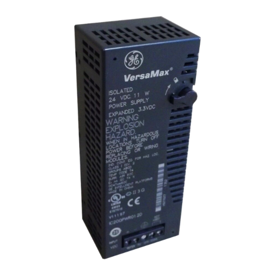
Power Supplies Chapter This chapter describes the VersaMax power supply modules. Refer to chapter 4 for information about the Power Supply Booster Carrier that can be used to install an additional “booster” power supply in the system. IC200PWR001 24 V DC Power Supply ... - Page 70 IC200PWR001 24 V DC Power Supply 24 V DC Power Supply IC200PWR001 provides backplane power for CPU, NIU, and I/O modules. When mounted on the CPU or NIU module, it serves as the main power supply for the station and supplies up to 1.5 A output current through 3.3 V and 5 V outputs, with up to 0.25 A on the 3.3 V output.
- Page 71 IC200PWR001 24 V DC Power Supply Specifications Input Voltage 18 to 30 V DC, 24 V DC nominal Input Power Holdup Time 10ms † Inrush Current 20 A for 6 ms maximum at 24 V DC † 25 A for 6 ms maximum at 30 V DC Output Voltage 5 V DC, 3.3 V DC Protection...
- Page 72 Wiring DC- must be grounded to frame / earth ground. DC- is grounded to frame internally in the Power Supply. As a result, floating power supplies cannot be used. For agency compliance, external MOV suppression is required from both the positive and negative inputs to frame ground or at the power line input of a system enclosure.
- Page 73 IC200PWR002 24 V DC Expanded 3.3 V Power Supply 24 V DC Expanded 3.3 V Power Supply IC200PWR002 provides backplane power for CPU, NIU, and I/O modules. When mounted on the CPU or NIU module, it serves as the main power supply for the station and supplies up to 1.5 A output current through 3.3 V and 5 V outputs, with up to 1.0 A on the 3.3 V output.
- Page 74 IC200PWR002 24 V DC Expanded 3.3 V Power Supply Specifications Input Voltage 18 to 30 V DC, 24 V DC nominal Input Power Holdup Time 10ms † Inrush Current 20 A for 6 ms maximum at 24 V DC † 25 A for 6 ms maximum at 30 V DC Output Voltage 5 V DC, 3.3 V DC...
- Page 75 Wiring DC- must be grounded to frame / earth ground. DC- is grounded to frame internally in the Power Supply. As a result, floating power supplies cannot be used. For agency compliance, external MOV suppression is required from both the positive and negative inputs to frame ground or at the power line input of a system enclosure.
- Page 76 IC200PWR011 and IC200PWR012 24 V DC Isolated Power Supplies VersaMax 24 V DC Isolated Power Supplies IC200PRW011 and IC200PRW012 provide backplane power for CPU, NIU, and I/O modules. Module backplane current consumption is summarized in GFK-1504, VersaMax I/O Manual. Both Isolated Power Supplies provide up to 1.5 A output current through 3.3-V and 5-V outputs.
- Page 77 Specifications Input Voltage 18 to 30 V DC, 24 V DC nominal Input Power 11 W Holdup Time 10ms Inrush Current 20 A maximum at 24 V DC 25 A maximum at 30 V DC Output Voltage 5 V DC, 3.3 V DC Protection Short circuit, overload, reverse polarity Isolation...
- Page 78 IC200PWR012 Thermal Derating 3.3 V Output vs. Ambient Temperature Temperature, °C 3-10 VersaMax Modules, Power Supplies and CarriersUser's Manual GFK-1504N...
- Page 79 IC200PWR101 120/240 V AC Power Supply 120/240 V AC Power Supply IC200PWR101 provides backplane power for CPU, NIU, and I/O modules. It supplies up to 1.5 A output current through 3.3 V and 5 V outputs, with up to 0.25 Am on the 3.3 V output. This is ample power for most installations.
- Page 80 IC200PWR101 120/240 V AC Power Supply Specifications Input Voltage 85 to 132 V AC with jumper installed, 120 V AC nominal 176 to 264 V AC w/o jumper installed, 240 V AC nominal Input Power 27VA Frequency 47 to 63Hz Holdup Time 20ms Output Voltage...
- Page 81 IC200PWR102 120/240 V AC Expanded 3.3 V Power Supply 120/240 V AC Expanded 3.3 Power Supply IC200PWR102 provides backplane power for CPU, NIU, and I/O modules. It supplies up to 1.5 A output current through 3.3 V and 5 V outputs, with up to 1.0 Amp on the 3.3 V output. Refer to Appendix C for module backplane current consumption.
- Page 82 IC200PWR102 120/240 V AC Expanded 3.3 V Power Supply Specifications Input Voltage 85 to 132 V AC with jumper installed, 120 V AC nominal 176 to 264 V AC w/o jumper installed, 240 V AC nominal Input Power 27VA Frequency 47 to 63Hz Holdup Time 20ms...
- Page 83 IC200PWR201 12V DC Power Supply 12V DC Power Supply IC200PWR201 provides backplane power for CPU, NIU, and I/O modules. It supplies up to 1.5 A output current through 3.3 V and 5 V outputs, with up to 0.25 A on the 3.3 V output. This is ample power for most installations.
- Page 84 IC200PWR201 12V DC Power Supply Specifications Input Voltage 9.6 to 15 V DC, 12V DC nominal Input Power Holdup Time 10ms Inrush Current 25 A at 12V DC 30A at 15 V DC Output Voltage 5 V DC, 3.3 V DC Protection Short circuit, overload, reverse polarity Output Current...
- Page 85 IC200PWR202 12V DC Expanded 3.3 V Power Supply 12V DC Expanded 3.3 V Power Supply IC200PWR202 provides backplane power for CPU, NIU, and I/O modules. It supplies up to 1.5 A output current through 3.3 V and 5 V outputs, with up to 1.0 A on the 3.3 V output. Refer to Appendix C for module backplane current consumption.
- Page 86 IC200PWR202 12V DC Expanded 3.3 V Power Supply Specifications Input Voltage 9.6 to 15 V DC, 12V DC nominal Input Power Holdup Time 10ms Inrush Current 25 A at 12V DC 30A at 15 V DC Output Voltage 5 V DC, 3.3 V DC Protection Short circuit, overload, reverse polarity Output Current...
-
Page 87: Carriers
Carriers Chapter This chapter describes the Carriers that provide mounting and backplane communications for VersaMax modules. IC200CHS001 Barrier-Style I/O Carrier IC200CHS002 Box-Style I/O Carrier IC200CHS003 Connector-Style I/O Carrier IC200CHS005 Spring-Style I/O Carrier IC200CHS022 Compact Box-Style I/O Carrier ... - Page 88 IC200CHS001 Barrier-Style I/O Carrier The Barrier-Style I/O Carrier (IC200CHS001) has 36 barrier-style terminals. It provides mounting, backplane communications, and field wiring for one I/O module. 110.5mm (4.35in) IC200CHS001 I/O CARRIER BARRIER STYLE 139.7mm (5.5in) The I/O module mounts lengthwise (parallel to the DIN rail) on this carrier. VersaMax Modules, Power Supplies and Carriers User's Manual GFK-1504N...
- Page 89 IC200CHS001 Barrier-Style I/O Carrier Din Rail Mounting The I/O carrier snaps easily onto a 7.5 mm x 35 mm DIN rail. The DIN rail must be electrically grounded to provide EMC protection. The rail must have a conductive (unpainted) corrosion-resistant finish. For applications requiring maximum resistance to mechanical vibration and shock, the carrier must also be panel-mounted.
- Page 90 IC200CHS001 Barrier-Style I/O Carrier Field Wiring Terminals Each terminal accommodates one or two solid or stranded wires from AWG #22 (avg. 0.36 mm cross section) to AWG #14 (avg. 2.1 mm cross section). A15 A16 B15 B16 A11 A12 B11 B12 The carrier accommodates current levels up to 2 A per point or 8 A per each power and ground, and a voltage range of up to 264 V AC.
- Page 91 IC200CHS002 Box-Style I/O Carrier The Box-Style I/O Carrier (IC200CHS002) has 36 IEC box-style terminals. It provides mounting, backplane communications, and field wiring for one I/O module. 110.5mm (4.35in) IC200CHS002 I/O CARRIER BOX STYLE 139.7mm (5.5in) The I/O module mounts lengthwise (parallel to the DIN rail) on this carrier. GFK-1504N Chapter 4 Carriers...
- Page 92 IC200CHS002 Box-Style I/O Carrier Din Rail Mounting The I/O carrier snaps easily onto a 7.5 mm x 35 mm DIN rail. The DIN rail must be electrically grounded to provide EMC protection. The rail must have a conductive (unpainted) corrosion-resistant finish. For applications requiring maximum resistance to mechanical vibration and shock, the carrier must also be panel-mounted.
- Page 93 IC200CHS002 Box-Style I/O Carrier Field Wiring Terminals Each terminal accommodates one solid or stranded AWG #14 (avg. 2.1 mm cross section) to AWG #22 (avg. 0.36 mm cross section) wire, or two wires up to AWG #18 (avg. 0.86 mm cross section).
- Page 94 IC200CHS003 Connector-Style I/O Carrier The Connector-Style I/O Carrier (IC200CHS003) has a 36-pin connector for attaching an I/O cable. It provides mounting, backplane communications, and field wiring for one I/O module. 66.8mm (2.63in) 133.4mm (5.25in) The I/O module mounts vertically (perpendicular to the DIN rail) on this carrier. VersaMax Modules, Power Supplies and Carriers User's Manual GFK-1504N...
- Page 95 IC200CHS003 Connector-Style I/O Carrier Din Rail Mounting The carrier snaps easily onto a 7.5 mm x 35 mm DIN rail. The DIN rail must be electrically grounded to provide EMC protection. The rail must have a conductive (unpainted) corrosion-resistant finish. For applications requiring maximum resistance to mechanical vibration and shock, the carrier must also be panel-mounted.
- Page 96 IC200CHS003 Connector-Style I/O Carrier Field Wiring Connection I/O devices can be wired directly to Interposing I/O Terminals, described separately in this chapter, or other types of terminal strips. Connection to the Connector Style I/O Carrier is made by cable. The following cables are available: IC200CBL105 2 connectors, 0.5m, no shield IC200CBL110 2 connectors, 1.0m, no shield...
- Page 97 IC200CHS005 Spring-Style I/O Carrier The Spring-Style I/O Carrier (IC200CHS005) has 36 spring-clamp style terminals for field wiring. It provides mounting, backplane communications, and field wiring for one I/O module. 110.5mm (4.35in) IC200CHS005 I/O CARRIER SPRING STYLE 139.7mm (5.5in) The I/O module mounts lengthwise (parallel to the DIN rail) on this carrier. GFK-1504N Chapter 4 Carriers 4-11...
- Page 98 IC200CHS005 Spring-Style I/O Carrier Din Rail Mounting The carrier snaps easily onto a 7.5 mm x 35 mm DIN rail. The DIN rail must be electrically grounded to provide EMC protection. The rail must have a conductive (unpainted) corrosion-resistant finish. For applications requiring maximum resistance to mechanical vibration and shock, the carrier must also be panel-mounted.
- Page 99 IC200CHS005 Spring-Style I/O Carrier Field Wiring Terminals Each terminal accommodates one solid or stranded AWG #14 (avg. 2.1 mm cross section) to AWG #22 (avg. 0.36 mm cross section) wire, or two wires up to AWG #18 (avg. 0.86 mm cross section).
- Page 100 IC200CHS022 Compact Box-Style I/O Carrier The Compact Box-Style I/O Carrier (IC200CHS022) has 36 IEC box-style terminals. It provides mounting, backplane communications, and field wiring for one I/O module. 66.8mm (2.63in) 163.5mm (6.45in) The I/O module mounts vertically (perpendicular to the DIN rail) on this carrier. 4-14 VersaMax Modules, Power Supplies and Carriers User's Manual GFK-1504N...
- Page 101 IC200CHS022 Compact Box-Style I/O Carrier Din Rail Mounting The I/O carrier snaps easily onto a 7.5 mm x 35 mm DIN rail. The DIN rail must be electrically grounded to provide EMC protection. The rail must have a conductive (unpainted) corrosion-resistant finish. For applications requiring maximum resistance to mechanical vibration and shock, the carrier must also be panel-mounted.
- Page 102 IC200CHS022 Compact Box-Style I/O Carrier Field Wiring Terminals Each terminal accommodates one solid or stranded AWG #14 (avg. 2.1 mm cross section) to AWG #22 (avg. 0.36 mm cross section) wire, or two wires up to AWG #18 (avg. 0.86 mm cross section).
- Page 103 IC200CHS025 Compact Spring-Style I/O Carrier The Compact Spring-Style I/O Carrier (IC200CHS025) has 36 IEC spring-style terminals. It provides mounting, backplane communications, and field wiring for one I/O module. 66.8mm (2.63in) 163.5mm (6.45in) The I/O module mounts vertically (perpendicular to the DIN rail) on this carrier. GFK-1504N Chapter 4 Carriers 4-17...
- Page 104 IC200CHS025 Compact Spring-Style I/O Carrier Din Rail Mounting The I/O carrier snaps easily onto a 7.5 mm x 35 mm DIN rail. The DIN rail must be electrically grounded to provide EMC protection. The rail must have a conductive (unpainted) corrosion-resistant finish. For applications requiring maximum resistance to mechanical vibration and shock, the carrier must also be panel-mounted.
- Page 105 IC200CHS025 Compact Spring-Style I/O Carrier Field Wiring Terminals Each terminal accommodates one solid or stranded AWG #14 (avg. 2.1 mm cross section) to AWG #22 (avg. 0.36 mm cross section) wire, or two wires up to AWG #18 (avg. 0.86 mm cross section).
- Page 106 IC200CHS006 Communications Carrier The Communications Carrier (IC200CHS006) provides mounting and backplane communications and field wiring for a fieldbus communications module. 66.8mm (2.63in) 133.4mm (5.25in) IC200CHS006 COMMUNICATIONS CARRIER Din Rail Mounting The carrier snaps easily onto a 7.5 mm x 35 mm DIN rail. The DIN rail must be electrically grounded to provide EMC protection.
- Page 107 IC200PNS001 and IC200PNS002 PROFINET Scanner Carriers The VersaMax PROFINET Scanner (PNS) module interfaces a remote node of VersaMax modules to a PROFINET IO-Controller. The PROFINET Scanner scans the modules in its node, retrieving input data and providing output data, and publishes input data on the PROFINET IO LAN at the configured production rate.
- Page 108 Features ▪ Supports redundant power supplies. Use of the second power supply is optional. ▪ Supports “hot swap” of a redundant power supply that is de-energized. ▪ Standard PROFINET alarm and diagnostics reporting. ▪ Supports configuration using Classless InterDomain Routing (CIDR) with subnetting and supernetting.
- Page 109 IC200PWB001 Power Supply Booster Carrier Power Supply Booster Carrier IC200PWB001 can be used to mount an additional power supply in sequence with other module carriers. A power supply mounted on a booster carrier provides power to all I/O modules to its right, or until the next booster power supply.
- Page 110 IC200PWB001 Power Supply Booster Carrier LED Indicators Two LEDs on the Power Supply Booster Carrier indicate its status: indicates that the attached booster power supply is functioning properly indicates that the CPU or NIU and attached booster power supply are functioning properly Din Rail Mounting The Power Supply Booster Carrier snaps easily onto a 7.5 mm x 35 mm DIN rail.
-
Page 111: Interposing Terminals And Auxiliary I/O Terminal Strips
Interposing Terminals and Auxiliary I/O Chapter Terminal Strips This chapter describes the Interposing I/O Terminals and Auxiliary I/O Terminal Strips that provide field wiring connections for I/O modules. IC200CHS011 Barrier-Style Interposing I/O Terminals IC200CHS012 Box-Style Interposing I/O Terminals ... - Page 112 IC200CHS011 Barrier-Style Interposing I/O Terminals The Barrier-Style Interposing I/O Terminals (IC200CHS011) provide interface to a Connector-Style I/O Carrier to field wiring. The unit has a connector for attaching a cable from the Connector-Style I/O Carrier and 36 barrier-style terminals. 110.5mm (4.35in) IC200CHS011 I/O INTERPOSING...
- Page 113 IC200CHS011 Barrier-Style Interposing I/O Terminals The carrier accommodates current levels up to 2 A per point or 8 A per each power and ground, and a voltage range of up to 264 V AC. Voltage transients up to 300 V AC will not damage the carrier. One or more Auxiliary I/O Terminal Strips can be added to provide extra field wiring connections if needed.
- Page 114 IC200CHS012 Box-Style Interposing I/O Terminals The Box-Style Interposing I/O Terminals (IC200CHS012) provide interface to a Connector-Style I/O Carrier to field wiring. The unit has a connector for attaching a cable from the Connector-Style I/O Carrier and 36 box-style terminals. A clear protective hinged door covers the wiring terminals. The board provided with each I/O module can be folded and inserted in this door.
- Page 115 IC200CHS012 Box-Style Interposing I/O Terminals Din Rail Mounting The Interposing I/O Terminals unit can be mounted on the same DIN rail as the Connector-Style I/O Carrier, or on a separate DIN rail as illustrated in the following figure. For applications requiring maximum resistance to mechanical vibration and shock, the Interposing I/O Terminals unit must also be panel- mounted.
- Page 116 IC200CHS014 Thermocouple Compensation Box-Style Interposing I/O Terminals The Thermocouple Compensation Box-Style Interposing I/O Terminals (IC200CHS014) provide interface to a Connector-Style I/O Carrier to field wiring from thermocouples. The unit has a connector for attaching a cable from the Connector-Style I/O Carrier and 36 box-style terminals. It includes a built-in thermistor that provides Local Cold Junction Compensation for thermocouple input measurements.
-
Page 117: Ic200Chs014 Thermocouple Compensation Box-Style Interposing
IC200CHS014 Thermocouple Compensation Box-Style Interposing I/O Terminals Din Rail Mounting The Interposing I/O Terminals unit can be mounted on the same DIN rail as the Connector-Style I/O Carrier, or on a separate DIN rail as illustrated in the following figure. For applications requiring maximum resistance to mechanical vibration and shock, the Interposing I/O Terminals unit must also be panel- mounted. -
Page 118: I/O Terminals
IC200CHS015 Spring-Style Interposing I/O Terminals The Spring-Style Interposing I/O Terminals (IC200CHS015) provide interface to a Connector-Style I/O Carrier to field wiring. It has a connector for attaching a cable from the Connector-Style I/O Carrier and 36 spring-clamp style terminals. A clear protective hinged door covers the wiring terminals. The board provided with each I/O module can be folded and inserted in this door. - Page 119 IC200CHS015 Spring-Style Interposing I/O Terminals Din Rail Mounting The Interposing I/O Terminals can be mounted on the same DIN rail as the Connector-Style I/O Carrier, or on a separate DIN rail as illustrated in the following figure. For applications requiring maximum resistance to mechanical vibration and shock, the Interposing I/O Terminals must also be panel-mounted.
-
Page 120: Ic200Chs101, Main Base Ic200Chs102, Expansion Base Disconnect-Style Interposing I/O Terminals
IC200CHS101, Main Base IC200CHS102, Expansion Base Disconnect-Style Interposing I/O Terminals The Disconnect-Style Interposing I/O Terminals (IC200CHS101 and IC200CHS102) provide interface to a VersaMax Connector-Style I/O Carrier to field wiring and provide an integrated disconnect option for field devices connected to VersaMax I/O module. Each device connected to the VersaMax I/O module may be individually disconnected from the control circuit by opening one of the two switches (signal or return) associated with it. - Page 121 Main Base, IC200CHS101 Expansion Base, IC200CHS102 Disconnect-Style Interposing I/O Terminals Main Base – IC200CHS101 This Interposing Disconnect Base has a connector (J1) for attaching a cable from the Connector-Style I/O Carrier and 36 box-style terminals for field I/O wiring and power connections. The I/O Interposing Disconnect Base also has an expansion connector (J2) that can be used to attach to an Interposing Disconnect Expansion Base (IC200CHS102).
- Page 122 IC200CHS101, Main Base IC200CHS102, Expansion Base Disconnect-Style Interposing I/O Terminals Expansion Base – IC200CHS102 The Interposing Disconnect Expansion Base has a connector (J2) for attaching a ribbon cable to the expansion connector of the Main Base (IC200CHS101) and 36 box-style terminals for field I/O wiring and power connections. The Expansion base includes a ribbon cable for connecting the expansion base to the main base.
- Page 123 Main Base, IC200CHS101 Expansion Base, IC200CHS102 Disconnect-Style Interposing I/O Terminals Compatible I/O Modules The following table provides a guideline for selecting the appropriate bases and wiring formats for VersaMax I/O modules. Modules that are incompatible with these Interposing Disconnect Bases are indicated by italics in the table. 1 Group 2 Groups CHS101 CHS102...
-
Page 124: Ic200Chs111, Main Base Ic200Chs112, Expansion Base Relay-Style Interposing I/O Terminals
IC200CHS111, Main Base IC200CHS112, Expansion Base Relay-Style Interposing I/O Terminals The Relay-Style Interposing I/O Terminals (IC200CHS111 and IC200CHS112) each provide dry contacts capable of switching high current outputs (up to 8A). The relays on these interposing terminals are intended to be controlled with standard 24 V DC 0.5A VersaMax output modules (IC200MDL740 and IC200MDL750). - Page 125 Main Base, IC200CHS111 Expansion Base, IC200CHS112 Relay-Style Interposing I/O Terminals Main Base – IC200CHS111 The Interposing Relay Base has a connector (J1) for attaching a cable from the Connector-Style I/O Carrier (IC200CHS003) and 50 box-style terminals for field I/O wiring and power connections. The Interposing Relay Base also has an expansion connector (J2) that can be used to attach to an Interposing Relay Expansion Base (IC200CHS112).
- Page 126 IC200CHS111, Main Base IC200CHS112, Expansion Base Relay-Style Interposing I/O Terminals Field Wiring Power for operation of the relay coils must be provided by an external 24V DC power supply. This power must be provided to both the main base and the expansion base.
- Page 127 Main Base, IC200CHS111 Expansion Base, IC200CHS112 Relay-Style Interposing I/O Terminals Relay Specifications The field-replaceable, form-C relay used in IC200CHS111 and IC200CHS112 is manufactured by Omron Electronics (part number G2R-14). The relay has the following specifications: Contact Ratings Number of Poles 1 Pole Resistive Load (cosΦ...
- Page 128 IC200CHS111, Main Base IC200CHS112, Expansion Base Relay-Style Interposing I/O Terminals Switching Current AC inductive load - AC resistive (cos φ =0.4) load DC inductive load (L/R = 7ms) DC resistive load 20 30 50 300 500 Life Expectancy 5000 250VAC / 30VDC 1000 resistive load 250VAC inductive load...
-
Page 129: Ic200Chs121, Main Base Ic200Chs122, Expansion Base Fuse-Style Interposing I/O Terminals
IC200CHS121, Main Base IC200CHS122, Expansion Base Fuse-Style Interposing I/O Terminals The Fuse-Style Interposing I/O Terminals (IC200CHS121 and IC200CHS122) provide interface to a Connector-Style I/O Carrier to field wiring and provide an integrated fuse solution for field devices connected to VersaMax I/O modules. Main and Expansion Base Two different versions of the Fuse-Style Interposing I/O Terminals are available, the main and expansion bases. - Page 130 Main Base, IC200CHS121 Expansion Base, IC200CHS122 Fuse-Style Interposing I/O Terminals Main Base – IC200CHS121 This interposing base has a connector (J1) for attaching a cable from the Connector-Style I/O Carrier and 36 box-style terminals for field I/O wiring and power connections. 137.16mm (5.4in) This base provides connection for the terminals on the “A”...
- Page 131 IC200CHS121, Main Base IC200CHS122, Expansion Base Fuse-Style Interposing I/O Terminals Expansion Base – IC200CHS122 This interposing base has a connector (J2) for attaching to the expansion connector of the Main Base (IC200CHS121) and provides 36 box-style terminals for field I/O wiring and power connections. 137.16mm (5.4in) The Expansion Base provides connection for terminals on the “B”...
- Page 132 Main Base, IC200CHS121 Expansion Base, IC200CHS122 Fuse-Style Interposing I/O Terminals Compatible I/O Modules The following table provides a guideline for selecting the appropriate bases and wiring formats for VersaMax I/O modules. Modules that are incompatible with these Interposing Fuse-Style Bases are indicated by italics in the following table. 1 Group 2 Groups CHS121 CHS122...
-
Page 133: Ic200Tbm001: Barrier-Style Auxiliary I/O Terminal Strip
IC200TBM001: Barrier-Style Auxiliary I/O Terminal Strip The Barrier-Style Auxiliary I/O Terminal Strip (IC200TBM001) has two groups of 6 internally-bussed barrier-style wiring terminals. The two groups are isolated from each other. It can be used to provide extra field wiring connections for terminal-style I/O Carriers and Interposing I/O Terminals. -
Page 134: Ic200Tbm002 Box-Style Auxiliary I/O Terminal Strip
IC200TBM002 Box-Style Auxiliary I/O Terminal Strip The Box-Style Auxiliary I/O Terminal Strip (IC200TBM002) has 18 internally - bussed IEC box-style wiring terminals. It can be used to provide extra field wiring connections for terminal-style I/O Carriers and Interposing I/O Terminals. Tabs for Attaching to previous carrier... -
Page 135: Ic200Tbm005 Spring-Style Auxiliary I/O Terminal Strip
IC200TBM005 Spring-Style Auxiliary I/O Terminal Strip The Spring-Style Auxiliary I/O Terminal Strip (IC200TBM005) has 18 internally - bussed spring-clamp style wiring terminals. It can be used to provide extra field wiring connections for terminal-style I/O Carriers and Interposing I/O Terminals. Tabs for Attaching to previous carrier... -
Page 136: Expansion Modules
Expansion Modules Chapter This chapter describes the following VersaMax expansion modules. IC200ETM001 Expansion Transmitter Module IC200ERM001 Expansion Receiver Module, Isolated IC200ERM002 Expansion Receiver Module, Non-isolated GFK-1504N... - Page 137 IC200ETM001 Expansion Transmitter Module The Expansion Transmitter Module IC200ETM001 (ETM) is used to expand a VersaMax PLC or Network Interface Unit (NIU) I/O station to include up to seven additional “racks” of VersaMax modules. Each expansion rack can include up to eight I/O and specialty modules, including the fieldbus communications modules.
- Page 138 IC200ETM001 Expansion Transmitter Module Connectors The 26-pin female D-shell connector on the front of the Expansion Transmitter is the expansion port for connecting to an Expansion Receiver Module. The 16-pin male connector on the upper left side of the Expansion Transmitter is the pass-though serial programming port.
- Page 139 IC200ETM001 Expansion Transmitter Module Expansion Rack Attachment The Expansion Transmitter installs on a DIN rail and attaches to the left side of a VersaMax CPU or NIU module on the same DIN rail. The Expansion Transmitter connects to up to seven Expansion Receiver Modules in expansion “racks”.
- Page 140 IC200ETM001 Expansion Transmitter Module Pass-Through Serial Port When the Expansion Transmitter is connected to a NIU module in an I/O station, firmware upgrades to the NIU are performed through the Expansion Transmitter’s pass-through serial port. (If there is no Expansion Transmitter installed, firmware upgrades are made through direct connection between the programmer and NIU, as displayed in the first illustration as follows.) The same serial cable, IC200CBL002, is used in both cases.
- Page 141 IC200ETM001 Expansion Transmitter Module Module Specifications Module Characteristics LED indicators PWR LED indicates 5 V DC power status EXP TX LED indicates expansion bus communication status Backplane current 5 V output: 44mA maximum consumption CIMPLICITY Versa Control Compatibility CPU001 CPU002 CPU005 CPUE05 DBI001 EBI001...
- Page 142 IC200ERM001 Expansion Receiver Module, Isolated The Expansion Receiver Module, Isolated (IC200ERM001) interfaces an expansion “rack” to a VersaMax PLC or NIU I/O Station system. The expansion rack can include up to eight Versamax I/O and special-purpose modules. A VersaMax power supply installed on the Expansion Receiver Module provides operating power for the modules in the expansion rack.
- Page 143 IC200ERM001 Expansion Receiver Module, Isolated Connectors The Expansion Receiver has two 26-pin female D-shell expansion ports. The upper port receives the cable from an Expansion Transmitter or upstream Expansion Receiver Module. The lower port is used to daisy-chain the expansion cable to the next expansion rack or to attach the terminator plug at the last rack.
- Page 144 LED Indicators Three LEDs display the status of module power, the expansion port, and the I/O modules. The PWR LED is ON when the module is receiving 5 V DC power from the attached power supply. It is OFF when there is no power supply attached or when the power supply itself is not receiving power.
- Page 145 IC200ERM001 Expansion Receiver Module, Isolated VersaMax Expansion Modules Standard RS-485 Differential Expansion Interface The Expansion Receiver Module connects to an Expansion Transmitter Module in a VersaMax PLC or VersaMax NIU I/O Station, or to an Expansion Receiver in a previous rack, as displayed in the following figure. Modules are connected using expansion cable IC200CBL6xx (xx represents the length in meters).
- Page 146 Cable Length and Data Rate By default, the module is set up to operate with the maximum length expansion cable at the default data rate of 250Kbits/second. If the total length of the expansion cable is less than 250 m and there are no non-isolated Expansion Receivers (IC200ERM002) in the expansion system, the VersaMax PLC programmer allows the data rate to be configured to 1Mbit/second.
- Page 147 IC200ERM001 Expansion Receiver Module, Isolated Module Specifications Module Characteristics LED indicators PWR LED indicates 5 V DC power status EXP RX LED indicates status of the expansion bus SCAN indicates whether CPU/NIU is scanning I/O in expansion racks Backplane current 5 V output: 430mA maximum.
- Page 148 IC200ERM001 Expansion Receiver Module, Isolated Modules for Expansion Racks All I/O and communications modules can be used in expansion racks. Some analog modules require specific module revisions as listed below. The date code is a 3-digit number on the outside of the module and on the shipping box. Module Revision Module Date Code Range...
- Page 149 IC200ERM002 Expansion Receiver Module, Non-isolated The non-isolated Expansion Receiver Module (IC200ERM002) interfaces an expansion “rack” to a VersaMax PLC or VersaMax NIU I/O Station system. The expansion rack can to include up to eight VersaMax I/O and special-purpose modules. A VersaMax power supply installed on the Expansion Receiver Module provides operating power for the modules in the expansion rack.
- Page 150 IC200ERM002: Expansion Receiver Module, Non-isolated Connectors The Expansion Receiver has two 26-pin female D-shell expansion ports. The upper port receives the cable from an Expansion Transmitter or upstream Expansion Receiver Module. The lower port is used to connect the expansion cable to the next expansion rack or to attach the terminator plug at the last rack.
- Page 151 IC200ERM002 Expansion Receiver Module, Non-isolated VersaMax Expansion Modules Standard RS-485 Differential Expansion Interface The Expansion Receiver Module connects to an Expansion Transmitter Module in a VersaMax PLC or VersaMax NIU I/O Station, or to an Expansion Receiver in a previous rack, as displayed below. Modules are connected using expansion cable IC200CBL6xx (xx represents the length in meters).
- Page 152 IC200ERM002 Expansion Receiver Module, Non-isolated Two-Rack Local System Expansion Receiver IC200ERM002 can also be used to connect a VersaMax PLC main rack or VersaMax NIU I/O Station to just one expansion rack without having an Expansion Transmitter Module in the main rack. This “single-ended”...
- Page 153 IC200ERM002 Expansion Receiver Module, Non-isolated Module Specifications Module Characteristics LED indicators PWR LED indicates 5 V DC power status EXP RX LED indicates expansion bus communications status SCAN LED indicates whether the CPU/NIU is scanning I/O in expansion racks Backplane current 5V output: 70mA maximum consumption 3.3V output: 20mA...
-
Page 154: Discrete Input Modules
Discrete Input Modules Chapter This chapter describes VersaMax discrete input modules. IC200MDL140 Input Module, 120 V AC 8 Points IC200MDL141 Input Module, 240 V AC 8 Points IC200MDL143 Input Module, 120 V AC Isolated 8 Points IC200MDL144 Input Module, 240 V AC Isolated 4 Points ... -
Page 155: Ic200Mdl140 Input Module, 120Vac 8 Points
IC200MDL140 Input Module, 120 V AC 8 Points Discrete Input Module IC200MDL140 provides one group of 8 discrete inputs. Inputs are positive logic or sourcing-type inputs; they receive current from AC input devices and return the current on the common. Input devices are connected between the input terminals and common terminals. - Page 156 IC200MDL140 Input Module, 120 V AC 8 Points Module Specifications Module Characteristics Points One group of 8 inputs Module ID FFFF8804 Isolation: User input to logic (optical) 250 V AC continuous; 1500 V AC for 1 minute and frame ground Group to group Not applicable Point to point...
- Page 157 IC200MDL140 Input Module, 120 V AC 8 Points Field Wiring Terminal Connection Terminal Connection Input 1 No connection Input 2 No connection Input 3 No connection Input 4 No connection Input 5 No connection Input 6 No connection Input 7 No connection Input 8 No connection...
- Page 158 IC200MDL141 Input Module, 240 V AC 8 Points Discrete Input Module IC200MDL141 provides one group of 8 discrete inputs. Inputs are positive logic or sourcing-type inputs; they receive current from AC input devices and return the current on the common. Input devices are connected between the input terminals and common terminals.
-
Page 159: Ic200Mdl141 Input Module, 240Vac 8 Points
IC200MDL141 Input Module, 240 V AC 8 Points Module Specifications Module Characteristics Points 1 group of 8 inputs Module ID FFFF8804 Isolation: User input to logic (optical) 250 V AC continuous; 1500 V AC for 1 minute and frame ground Group to group Not applicable Point to point... - Page 160 IC200MDL141 Input Module, 240 V AC 8 Points Field Wiring Terminal Connection Terminal Connection Input 1 No connection Input 2 No connection Input 3 No connection Input 4 No connection Input 5 No connection Input 6 No connection Input 7 No connection Input 8 No connection...
-
Page 161: Ic200Mdl143 Input Module, 120Vac Isolated 8 Points
IC200MDL143 Input Module, 120 V AC Isolated 8 Points Discrete Input Module IC200MDL143 provides 8 isolated discrete inputs. Inputs are positive logic or sourcing-type inputs; they receive current from AC input devices and return the current on the common. Each input has its own return. IC200MDL143 INPUT 120VAC... - Page 162 IC200MDL143 Input Module, 120 V AC Isolated 8 Points Module Specifications Module Characteristics Points 8 Isolated Inputs Module ID FFFF8804 Isolation: User input to logic (optical) 250 V AC continuous; 1500 V AC for 1 minute and frame ground Group to group Not applicable Point to point 250 V AC continuous;...
- Page 163 IC200MDL143 Input Module, 120 V AC Isolated 8 Points Field Wiring Terminal Connection Terminal Connection Input 1 No connection Input 1 Return No connection Input 2 No connection Input 2 Return No connection Input 3 No connection Input 3 Return No connection Input 4 No connection...
-
Page 164: Ic200Mdl144 Input Module, 240Vac Isolated 4 Points
IC200MDL144 Input Module, 240 V AC Isolated 4 Points Discrete Input Module IC200MDL144 provides 4 isolated discrete inputs. Inputs are positive logic or sourcing-type inputs; they receive current from AC input devices and return the current on the common. Input devices are connected between the input terminals and common terminals. - Page 165 IC200MDL144 Input Module, 240 V AC Isolated 4 Points Module Specifications Module Characteristics Points 4 Isolated Inputs Module ID FFFF8802 Isolation: User input to logic (optical) 500 V AC continuous; 2000 V AC for 1 minute and frame ground Group to group None Point to point 500 V AC continuous;...
- Page 166 IC200MDL144 Input Module, 240 V AC Isolated 4 Points Field Wiring Terminal Connection Terminal Connection No connection No connection No connection No connection Input 1 No connection Input 1 Return No connection No connection No connection No connection No connection Input 2 No connection Input 2 Return...
-
Page 167: Ic200Mdl240 Input Module, 120Vac 16 Points
IC200MDL240 Input Module, 120 V AC 16 Points Discrete input module IC200MDL240 provides two groups of 8 discrete inputs each. Inputs are positive logic or sourcing-type inputs; they receive current from AC input devices and return the current on the common. Input devices are connected between the input terminals and common terminals. - Page 168 IC200MDL240 Input Module, 120 V AC 16 Points Module Specifications Module Characteristics Points Two groups of 8 inputs Module ID 88048804 Isolation: User input to logic (optical) 250 V AC continuous; 1500 V AC for 1 minute and frame ground Group to group 250 V AC continuous;...
- Page 169 IC200MDL240 Input Module, 120 V AC 16 Points Field Wiring Terminal Connection Terminal Connection Input 1 Input 9 Input 2 Input 10 Input 3 Input 11 Input 4 Input 12 Input 5 Input 13 Input 6 Input 14 Input 7 Input 15 Input 8 Input 16...
- Page 170 IC200MDL240 Input Module, 120 V AC 16 Points Thermal Derating The number of points that can be on at the same time depends on the ambient temperature, the external voltage, and the orientation of the module and DIN rail. No thermal derating for these installations. No derating at 120 V AC.
-
Page 171: Ic200Mdl241 Input Module, 240Vac16 Points
IC200MDL241 Input Module, 240 V AC16 Points Discrete Input Module IC200MDL241 provides two groups of 8 discrete inputs. Inputs are positive logic or sourcing-type inputs; they receive current from AC input devices and return the current on the common. Input devices are connected between the input terminals and common terminals. - Page 172 IC200MDL241 Input Module, 240 V AC16 Points Module Specifications Module Characteristics Points 16 inputs (2 groups of 8) Module ID 88048804 Isolation: User input to logic (optical) 250 V AC continuous; 1500 V AC for 1 minute and frame ground Group to group 250 V AC continuous;...
- Page 173 IC200MDL241 Input Module, 240 V AC16 Points Field Wiring Terminal Connection Terminal Connection Input 1 Input 9 Input 2 Input 10 Input 3 Input 11 Input 4 Input 12 Input 5 Input 13 Input 6 Input 14 Input 7 Input 15 Input 8 Input 16 No connection...
- Page 174 IC200MDL241 Input Module, 240 V AC16 Points Thermal Derating The number of points that can be on at the same time depends on the ambient temperature, the external voltage, and the orientation of the module and DIN rail. No thermal derating for these installations. No derating at 240 V AC.
-
Page 175: Ic200Mdl243 Input Module, 120Vac Isolated 16 Points
IC200MDL243 Input Module, 120 V AC Isolated 16 Points Discrete input module IC200MDL243 provides 16 isolated input points. Inputs are positive logic or sourcing-type inputs; they receive current from AC input devices and return the current on the common. Each input has its own return. IC200MDL243 INPUT 120VAC... - Page 176 IC200MDL243 Input Module, 120 V AC Isolated 16 Points Module Specifications Module Characteristics Points 16 Isolated Inputs Module ID 88048804 Isolation: User input to logic (optical) 250 V AC continuous; 1500 V AC for 1 minute and frame ground Group to group Not applicable Point to point 250 V AC continuous;...
- Page 177 IC200MDL243 Input Module, 120 V AC Isolated 16 Points Field Wiring Terminal Connection Terminal Connection Input 1 Input 9 Input 1 Return Input 9 Return Input 2 Input 10 Input 2 Return Input 10 Return Input 3 Input 11 Input 3 Return Input 11 Return Input 4 Input 12...
- Page 178 IC200MDL243 Input Module, 120 V AC Isolated 16 Points Thermal Derating The number of points that can be on at the same time depends on the ambient temperature, the external voltage, and the orientation of the module and DIN rail. No thermal derating for these installations.
-
Page 179: Ic200Mdl244 Input Module, 240Vac Isolated 8 Points
IC200MDL244 Input Module, 240 V AC Isolated 8 Points Discrete Input Module IC200MDL244 provides 8 isolated discrete inputs. Inputs are positive logic or sourcing-type inputs; they receive current from AC input devices and return the current on the common. Input devices are connected between the input terminals and common terminals. - Page 180 IC200MDL244 Input Module, 240 V AC Isolated 8 Points Module Specifications Module Characteristics Points 8 Isolated Inputs Module ID 88028802 Isolation: User input to logic (optical) 500 V AC continuous; 2000 V AC for 1 minute and frame ground Group to group None Point to point 500 V AC continuous;...
- Page 181 IC200MDL244 Input Module, 240 V AC Isolated 8 Points Field Wiring Terminal Connection Terminal Connection No connection No connection No connection No connection Input 1 Input 5 Input 1 Return Input 5 Return No connection No connection No connection No connection Input 2 Input 6 Input 2 Return...
-
Page 182: Ic200Mdl631 Input Module, 125Vdc Pos/Neg Logic Isolated 8 Points
IC200MDL631 Input Module, 125 V DC Pos/Neg Logic Isolated 8 Points Discrete input module IC200MDL631 provides 8 discrete isolated inputs. Inputs can be either positive logic inputs that receive current from input devices and return the current on the return, or negative-logic inputs that receive current from the return and return current to the input device. - Page 183 IC200MDL631 Input Module, 125 V DC Pos/Neg Logic Isolated 8 Points Module Specifications Module Characteristics Points 8 isolated inputs Module ID FFFF8004 Isolation: User input to logic (optical) 250 V AC continuous; 1500 V AC for 1 minute and to frame ground Point to point 250 V AC continuous;...
- Page 184 IC200MDL631 Input Module, 125 V DC Pos/Neg Logic Isolated 8 Points Field Wiring Terminal Connection Terminal Connection Input 1 No connection Input 1 return No connection Input 2 No connection Input 2 return No connection Input 3 No connection Input 3 return No connection Input 4 No connection...
-
Page 185: Ic200Mdl632 Input Module, 125Vdc Pos/Neg Logic Isolated 16 Points
IC200MDL632 Input Module, 125 V DC Pos/Neg Logic Isolated 16 Points Discrete input module IC200MDL632 provides 16 discrete isolated inputs. Inputs can be either positive logic inputs that receive current from input devices and return the current on the return, or negative-logic inputs that receive current from the return and return current to the input device. - Page 186 IC200MDL632 Input Module, 125 V DC Pos/Neg Logic Isolated 16 Points Module Specifications Module Characteristics Points 16 isolated inputs Module ID 80048004 Isolation: User input to logic 250 V AC continuous; 1500 V AC for 1 minute (optical) and to frame ground 250 V AC continuous;...
- Page 187 IC200MDL632 Input Module, 125 V DC Pos/Neg Logic Isolated 16 Points Field Wiring Terminal Connection Terminal Connection Input 1 Input 9 Input 1 return Input 9 return Input 2 Input 10 Input 2 return Input 10 return Input 3 Input 11 Input 3 return Input 11 return Input 4...
- Page 188 IC200MDL632 Input Module, 125 V DC Pos/Neg Logic Isolated 16 Points Thermal Derating The number of points that can be on at the same time depends on the ambient temperature, the external voltage, and the orientation of the module and DIN rail.
-
Page 189: Ic200Mdl635 Input Module, 48Vdc Pos/Neg Logic Grouped 16 Points
IC200MDL635 Input Module, 48 V DC Pos/Neg Logic Grouped 16 Points Discrete input module IC200MDL635 provides two groups of 8 discrete inputs. Inputs in each group can be either positive logic inputs that receive current from input devices and return the current on the common, or negative-logic inputs that receive current from the common and return current to the input device. - Page 190 IC200MDL635 Input Module, 48 V DC Pos/Neg Logic Grouped 16 Points Module Specifications Module Characteristics Points 16 inputs (2 groups of 8) Module ID FFFF8008 Isolation: User input to logic (optical) 250 V AC continuous; 1500 V AC for 1 minute and to frame ground Group to Group 250 V AC continuous;...
- Page 191 IC200MDL635 Input Module, 48 V DC Pos/Neg Logic Grouped 16 Points Field Wiring Terminal Connection Terminal Connection Input 1 No connection Input 2 No connection Input 3 No connection Input 4 No connection Input 5 No connection Input 6 No connection Input 7 No connection Input 8...
- Page 192 IC200MDL636 Input Module, 48 V DC Pos/Neg Logic Grouped 32 Points Discrete input module IC200MDL636 provides four groups of 8 discrete inputs. Inputs in each group can be either positive logic inputs that receive current from input devices and return the current on the common, or negative-logic inputs that receive current from the common and return current to the input device.
-
Page 193: Ic200Mdl636 Input Module, 48Vdc Pos/Neg Logic Grouped 32 Points
IC200MDL636 Input Module, 48 V DC Pos/Neg Logic Grouped 32 Points Module Specifications Module Characteristics Points 32 (4 groups of 8) Module ID 80088008 Isolation: User input to logic (optical) 250 V AC continuous; 1500 V AC for 1 minute and to frame ground Group to group 250 V AC continuous;... - Page 194 IC200MDL636 Input Module, 48 V DC Pos/Neg Logic Grouped 32 Points Field Wiring Terminal Connection Terminal Connection Input 1 Input 17 Input 2 Input 18 Input 3 Input 19 Input 4 Input 20 Input 5 Input 21 Input 6 Input 22 Input 7 Input 23 Input 8...
- Page 195 IC200MDL636 Input Module, 48 V DC Pos/Neg Logic Grouped 32 Points Thermal Derating The number of points that can be on at the same time depends on the ambient temperature, the external voltage, and the orientation of the module and DIN rail.
-
Page 196: Ic200Mdl640 Input Module, 24Vdc Pos/Neg Logic 16 Points
IC200MDL640 Input Module, 24 V DC Pos/Neg Logic 16 Points Discrete input module IC200MDL640 provides two groups of 8 discrete inputs. Inputs in each group can be either positive logic inputs that receive current from input devices and return the current on the common, or negative-logic inputs that receive current from the common and return current to the input device. - Page 197 IC200MDL640 Input Module, 24 V DC Pos/Neg Logic 16 Points Module Specifications Module Characteristics Points 16 inputs (2 groups of 8) Module ID FFFF8008 Isolation: User input to logic (optical) 250 V AC continuous; 1500 V AC for 1 minute and to frame ground Group to Group 250 V AC continuous;...
- Page 198 IC200MDL640 Input Module, 24 V DC Pos/Neg Logic 16 Points Field Wiring Terminal Connection Terminal Connection Input 1 No connection Input 2 No connection Input 3 No connection Input 4 No connection Input 5 No connection Input 6 No connection Input 7 No connection Input 8...
-
Page 199: Ic200Mdl643 Input Module, 5/12Vdc Pos/Neg Logic Grouped 16 Points
IC200MDL643 Input Module, 5/12 V DC Pos/Neg Logic Grouped 16 Points Discrete input module IC200MDL643 provides two groups of 8 discrete inputs. Inputs in each group can be either positive logic inputs that receive current from input devices and return the current on the common, or negative-logic inputs that receive current from the common and return current to the input device. - Page 200 IC200MDL643 Input Module, 5/12 V DC Pos/Neg Logic Grouped 16 Points Module Specifications Module Characteristics Points 16 inputs (2 groups of 8) Module ID FFFF8008 Isolation: User input to logic (optical) 250 V AC continuous; 1500 V AC for 1 minute and to frame ground Group to Group 250 V AC continuous;...
- Page 201 IC200MDL643 Input Module, 5/12 V DC Pos/Neg Logic Grouped 16 Points Field Wiring Terminal Connection Terminal Connection Input 1 No connection Input 2 No connection Input 3 No connection Input 4 No connection Input 5 No connection Input 6 No connection Input 7 No connection Input 8...
- Page 202 IC200MDL643 Input Module, 5/12 V DC Pos/Neg Logic Grouped 16 Points Wiring for TTL Inputs To be compatible with TTL outputs, the negative logic configuration should be used as follows. User Circuit Common x TTL IC Output Input x GFK-1504N Chapter 7 Discrete Input Modules 7-49...
-
Page 203: Ic200Mdl644 Input Module, 5/12Vdc Pos/Neg Logic Grouped 32 Point
IC200MDL644 Input Module, 5/12 V DC Pos/Neg Logic Grouped 32 Point Discrete input module IC200MDL644 provides four groups of 8 discrete inputs. Inputs in each group can be either positive logic inputs that receive current from input devices and return the current on the common, or negative-logic inputs that receive current from the common and return current to the input device. - Page 204 IC200MDL644 Input Module, 5/12 V DC Pos/Neg Logic Grouped 32 Point Module Specifications Module Characteristics Points 32 (4 groups of 8) Module ID 80088008 Isolation: User input to logic (optical) 250 V AC continuous; 1500 V AC for 1 minute and to frame ground Group to group 250 V AC continuous;...
- Page 205 IC200MDL644 Input Module, 5/12 V DC Pos/Neg Logic Grouped 32 Point Field Wiring Terminal Connection Terminal Connection Input 1 Input 17 Input 2 Input 18 Input 3 Input 19 Input 4 Input 20 Input 5 Input 21 Input 6 Input 22 Input 7 Input 23 Input 8...
- Page 206 IC200MDL644 Input Module, 5/12 V DC Pos/Neg Logic Grouped 32 Point Wiring for TTL Inputs To be compatible with TTL outputs, the negative logic configuration should be used as follows. User Circuit Common x TTL IC Output Input x GFK-1504N Chapter 7 Discrete Input Modules 7-53...
-
Page 207: Ic200Mdl650 Input Module, 24Vdc Pos/Neg Logic 32 Points
IC200MDL650 Input Module, 24 V DC Pos/Neg Logic 32 Points Discrete input module IC200MDL650 provides four groups of 8 discrete inputs. Inputs in each group can be either positive logic inputs that receive current from input devices and return the current on the common, or negative-logic inputs that receive current from the common and return current to the input device. - Page 208 IC200MDL650 Input Module, 24 V DC Pos/Neg Logic 32 Points Module Specifications Module Characteristics Points 32 (4 groups of 8) Module ID 80088008 Isolation: User input to logic (optical) 250 V AC continuous; 1500 V AC for 1 minute and to frame ground Group to group 250 V AC continuous;...
- Page 209 IC200MDL650 Input Module, 24 V DC Pos/Neg Logic 32 Points Field Wiring Terminal Connection Terminal Connection Input 1 Input 17 Input 2 Input 18 Input 3 Input 19 Input 4 Input 20 Input 5 Input 21 Input 6 Input 22 Input 7 Input 23 Input 8...
- Page 210 IC200MDL650 Input Module, 24 V DC Pos/Neg Logic 32 Points Thermal Derating The number of points that can be on at the same time depends on the ambient temperature, the external voltage, and the orientation of the module and DIN rail.
-
Page 211: Discrete Output Modules
Discrete Output Modules Chapter This chapter describes VersaMax discrete output modules. IC200MDL329 Output Module, 120VAC 0.5 A, Isolated 8 Points IC200MDL330 Output Module, 120VAC 0.5 A, Isolated 16 Points IC200MDL331 Output Module, 120VAC 2.0 A, Isolated 8 Points ... - Page 212 IC200MDL329 Output Module, 120 V AC 0.5 A, Isolated 8 Points Discrete output module IC200MDL329 provides 8 isolated outputs. IC200MDL329 OUTPUT 120VAC 1234567 An external 120 V AC power supply must be provided to switch power to the loads. Intelligent processing for this module is performed by the CPU or NIU. The module receives 8 bits of discrete output data.
-
Page 213: Points
IC200MDL329 Output Module, 120 V AC 0.5 A, Isolated 8 Points Module Specifications Module Characteristics Points 8 isolated outputs Module ID FFFF8840 Isolation: User input to logic (optical) 250 V AC continuous; 1500 V AC for 1 minute and to frame ground Group to group Not applicable Point to point... - Page 214 IC200MDL329 Output Module, 120 V AC 0.5 A, Isolated 8 Points Field Wiring Terminal Connection Terminal Connection Output 1 No connection Output 1 Ret No connection Output 2 No connection Output 2 Ret No connection Output 3 No connection Output 3 Ret No connection Output 4 No connection...
- Page 215 Wiring Connections for Carriers with Three Rows of Terminals IC200CHS001, 022, 025 IC200CHS011 GFK-1504N Chapter 8 Discrete Output Modules...
- Page 216 IC200MDL329 Output Module, 120 V AC 0.5 A, Isolated 8 Points Thermal Derating The number of points that can be on at the same time depends on the ambient temperature, the external voltage, and the orientation of the module and DIN rail.
- Page 217 IC200MDL330 Output Module, 120 V AC 0.5 A, Isolated 16 Points Discrete output module IC200MDL330 provides 16 isolated outputs. IC200MDL330 OUTPUT 120VAC .5A 16PT 1234567 10 11 12 13 14 15 16 An external 120 V AC power supply must be provided to switch power to the loads.
-
Page 218: Points
IC200MDL330 Output Module, 120 V AC 0.5 A, Isolated 16 Points Module Specifications Module Characteristics Points 16 isolated outputs Module ID 88408840 Isolation: User input to logic (optical) 250 V AC continuous; 1500 V AC for 1 minute and to frame ground Group to group 250 V AC continuous;... - Page 219 IC200MDL330 Output Module, 120 V AC 0.5 A, Isolated 16 Points Field Wiring Terminal Connection Terminal Connection Output 1 Output 9 Output 1 Ret Output 9 Ret Output 2 Output 10 Output 2 Ret Output 10 Ret Output 3 Output 11 Output 3 Ret Output 11 Ret Output 4...
- Page 220 IC200MDL330 Output Module, 120 V AC 0.5 A, Isolated 16 Points Thermal Derating The number of points that can be on at the same time depends on the ambient temperature, the external voltage, and the orientation of the module and DIN rail.
- Page 221 IC200MDL331 Output Module, 120 V AC 2.0 A, Isolated 8 Points Discrete output module IC200MDL331 provides 8 isolated outputs. IC200MDL331 OUTPUT 120VAC 2A 8PT 1234567 An external 120 V AC power supply must be provided to switch power to the loads.
-
Page 222: Points
IC200MDL331 Output Module, 120 V AC 2.0 A, Isolated 8 Points Module Specifications Module Characteristics Points 8 isolated outputs Module ID FFFF8840 Isolation: User input to logic (optical) 250 V AC continuous; 1500 V AC for 1 minute and to frame ground Group to group Not applicable Point to point... - Page 223 IC200MDL331 Output Module, 120 V AC 2.0 A, Isolated 8 Points Field Wiring Terminal Connection Terminal Connection No connection Output 1 No connection Output 1 Ret No connection Output 2 No connection Output 2 Ret No connection Output 3 No connection Output 3 Ret No connection Output 4...
- Page 224 IC200MDL331 Output Module, 120 V AC 2.0 A, Isolated 8 Points Thermal Derating The number of points that can be on at the same time depends on the ambient temperature, the output current, and the orientation of the module and DIN rail. The following charts display thermal deratings for the module at 120 V AC with the indicated output current per point.
- Page 225 IC200MDL730 Output Module, 24 V DC Positive Logic 2.0 As, w/ESCP 8 Points Discrete output module IC200MDL730 provides one group of 8 discrete outputs. Each point has electronic overcurrent protection and short circuit protection, and generates a fault if either condition exists. The outputs are positive or sourcing type outputs.
- Page 226 IC200MDL730 Output Module, 24 V DC Positive Logic 2.0 A, w/ESCP 8 Points Module Specifications Module Characteristics Points 1 group of 8 outputs Module ID FFFF8140 Isolation: User input to logic (optical) 250 V AC continuous; 1500 V AC for 1 minute and to frame ground Group to group Not applicable...
- Page 227 characteristics. Additional best practices including minimizing wiring resistance from the external power supply to the module must be observed. IC200MDL730 Output Module, 24 V DC Positive Logic 2.0 As, w/ESCP 8 Points Field Wiring Terminal Connection Terminal Connection No connection Output 1 No connection No connection...
- Page 228 IC200MDL740 Output Module, 12/24 V DC Positive Logic 0.5 A, 16 Points Discrete output module IC200MDL740 provides one group of 16 discrete outputs. The outputs are positive or sourcing type outputs. They switch the loads to the positive side of the DC supply and thus supply current to the loads. 10 11 12 13 14 15 16 IC200MDL740 OUTPUT...
- Page 229 IC200MDL740 Output Module, 12/24 V DC Positive Logic 0.5 A, 16 Points Module Specifications Module Characteristics Points 1 group of 16 outputs Module ID FFFF8080 Isolation: User input to logic (optical) 250 V AC continuous; 1500 V AC for 1 minute and to frame ground Group to group Not applicable...
- Page 230 IC200MDL740 Output Module, 12/24 V DC Positive Logic 0.5 A, 16 Points Field Wiring Terminal Connection Terminal Connection Output 1 No connection Output 2 No connection Output 3 No connection Output 4 No connection Output 5 No connection Output 6 No connection Output 7 No connection...
- Page 231 Wiring Connections for Carriers with Three Rows of Terminals IC200CHS001, 022, 025 IC200CHS011 GFK-1504N Chapter 8 Discrete Output Modules 8-21...
- Page 232 IC200MDL740 Output Module, 12/24 V DC Positive Logic 0.5 A, 16 Points Thermal Derating The number of points that can be on at the same time depends on the ambient temperature, the external voltage, and the orientation of the module and DIN rail.
- Page 233 IC200MDL741 Output Module, 24 V DC Positive Logic 0.5 A, w/ESCP 16 Points Discrete output module IC200MDL741 provides one group of 16 discrete outputs. Each point has electronic overcurrent protection and short circuit protection, and generates a fault if either condition exists. The outputs are positive or sourcing type outputs.
- Page 234 IC200MDL741 Output Module, 24 V DC Positive Logic 0.5 A, w/ESCP 16 Points Module Specifications Module Characteristics Points 1 group of 16 outputs Module ID FFFF8080 Isolation: User input to logic (optical) 250 V AC continuous; 1500 V AC for 1 minute and to frame ground Group to group Not applicable...
- Page 235 IC200MDL741 Output Module, 24 V DC Positive Logic 0.5 A, w/ESCP 16 Points Field Wiring Terminal Connection Terminal Connection Output 1 No connection Output 2 No connection Output 3 No connection Output 4 No connection Output 5 No connection Output 6 No connection Output 7 No connection...
- Page 236 IC200MDL741 Output Module, 24 V DC Positive Logic 0.5 A, w/ESCP 16 Points Thermal Derating The number of points that can be on at the same time depends on the ambient temperature, the external voltage, and the orientation of the module and DIN rail.
- Page 237 IC200MDL742 Output Module, 24 V DC Positive Logic 0.5 A, w/ESCP 32 Points Discrete output module IC200MDL742 provides two groups of 16 discrete outputs. Each point has electronic overcurrent protection and short circuit protection, and generates a fault if either condition exists. The outputs are positive or sourcing type outputs.
- Page 238 IC200MDL742 Output Module, 24 V DC Positive Logic 0.5 A, w/ESCP 32 Points Module Specifications Module Characteristics Points 2 groups of 16 outputs Module ID 80808080 Isolation: User input to logic (optical) and to 250 V AC continuous; 1500 V AC for 1 minute frame ground Group to group 250 V AC continuous;...
- Page 239 IC200MDL742 Output Module, 24 V DC Positive Logic 0.5 A, w/ESCP 32 Points Thermal Derating The number of points that can be on at the same time depends on the ambient temperature, the external voltage, and the orientation of the module and DIN rail.
- Page 240 IC200MDL742 Output Module, 24 V DC Positive Logic 0.5 A, w/ESCP 32 Points Field Wiring Terminal Connection Terminal Connection Output 1 Output 17 Output 2 Output 18 Output 3 Output 19 Output 4 Output 20 Output 5 Output 21 Output 6 Output 22 Output 7 Output 23...
- Page 241 IC200MDL743 Output Module, 5/12/24 V DC Negative Logic 0.5 A, 16 Points Discrete output module IC200MDL743 provides one group of 16 discrete outputs. The outputs are negative or sinking type outputs. They switch the loads to the negative (return) side of the DC supply and thus receive current from the loads.
- Page 242 IC200MDL743 Output Module, 5/12/24 V DC Negative Logic 0.5 A, 16 Points Module Specifications Module Characteristics Points 1 group of 16 outputs Module ID FFFF8080 Isolation: User input to logic (optical) 250 V AC continuous; 1500 V AC for 1 minute and to frame ground Group to group Not applicable...
- Page 243 IC200MDL743 Output Module, 5/12/24 V DC Negative Logic 0.5 A, 16 Points Field Wiring The 16 outputs form one group with a DC+ and a DC- terminal. Terminal Connection Terminal Connection Output 1 No connection Output 2 No connection Output 3 No connection Output 4 No connection...
- Page 244 IC200MDL744 Output Module, 5/12/24 V DC Negative Logic 0.5 A, 32 Points Discrete output module IC200MDL744 provides two groups of 16 discrete outputs. The outputs are negative or sinking type outputs. They switch the loads to the negative (return) side of the DC supply and thus receive current from the loads.
- Page 245 IC200MDL744 Output Module, 5/12/24 V DC Negative Logic 0.5 A, 32 Points Module Specifications Module Characteristics Points 2 groups of 16 outputs Module ID 80808080 Isolation: User input to logic (optical) 250 V AC continuous; 1500 V AC for 1 minute and to frame ground Group to group 250 V AC continuous;...
- Page 246 IC200MDL744 Output Module, 5/12/24 V DC Negative Logic 0.5 A, 32 Points Field Wiring Terminal Connection Terminal Connection Output 1 Output 17 Output 2 Output 18 Output 3 Output 19 Output 4 Output 20 Output 5 Output 21 Output 6 Output 22 Output 7 Output 23...
- Page 247 IC200MDL744 Output Module, 5/12/24 V DC Negative Logic 0.5 A, 32 Points Thermal Derating The number of points that can be on at the same time depends on the ambient temperature, the external voltage, and the orientation of the module and DIN rail.
- Page 248 IC200MDL750 Output Module, 12/24 V DC Positive Logic 0.5 A, 32 Points Discrete output module IC200MDL750 provides two groups of 16 discrete outputs. The outputs are positive or sourcing type outputs. They switch the loads to the positive side of the DC supply and thus supply current to the loads. 10 11 12 13 14 15 16 IC200MDL750 OUTPUT...
- Page 249 IC200MDL750 Output Module, 12/24 V DC Positive Logic 0.5 A, 32 Points Module Specifications Module Characteristics Points 2 groups of 16 outputs Module ID 80808080 Isolation: User input to logic (optical) 250 V AC continuous; 1500 V AC for 1 minute and to frame ground Group to group 250 V AC continuous;...
- Page 250 IC200MDL750 Output Module, 12/24 V DC Positive Logic 0.5 A, 32 Points Field Wiring Terminal Connection Terminal Connection Output 1 Output 17 Output 2 Output 18 Output 3 Output 19 Output 4 Output 20 Output 5 Output 21 Output 6 Output 22 Output 7 Output 23...
- Page 251 IC200MDL750 Output Module, 12/24 V DC Positive Logic 0.5 A, 32 Points Thermal Derating The number of points that can be on at the same time depends on the ambient temperature, the external voltage, and the orientation of the module and DIN rail.
- Page 252 IC200MDL930 Output Module, Relay 2.0 A Isolated Form A 8 Points Relay output module IC200MDL930 provides 8 individually-isolated Form A relay outputs. The contact is closed when the host CPU is active and the corresponding output logic bit is “1”. IC200MDL930 OUTPUT RELAY...
- Page 253 IC200MDL930 Output Module, Relay 2.0 A Isolated Form A 8 Points Module Specifications Module Characteristics Points 8 individually isolated Form A relay outputs Module ID FFFF8040 Isolation: User input to logic (optical) 250 V AC continuous; 1500 V AC for 1 minute and to frame ground Group to group Not applicable...
- Page 254 IC200MDL930 Output Module, Relay 2.0 A Isolated Form A 8 Points Field Wiring Terminal Connection Terminal Connection Output 1-1 No connection Output 1-2 No connection Output 2-1 No connection Output 2-2 No connection Output 3-1 No connection Output 3-2 No connection Output 4-1 No connection Output 4-2...
- Page 255 IC200MDL930 Output Module, Relay 2.0 A Isolated Form A 8 Points Backplane Power Drain per Point The module’s backplane 5 volt power requirement increases as the number of points that are simultaneously on increases. The following chart displays the relationship between the number of points on and the maximum current required.
- Page 256 IC200MDL940 Output Module, Relay 2.0 A, Isolated Form A 16 Points Relay Output Module IC200MDL940 provides 16 individually-isolated Form A relay outputs. The contact is closed when the host CPU is active and the corresponding output logic bit is “1”. IC200MDL940 OUTPUT RELAY...
- Page 257 IC200MDL940 Output Module, Relay 2.0 A, Isolated Form A 16 Points Module Specifications Module Characteristics Points 16 individually isolated Form A relay outputs Module ID 80408040 Isolation: User input to logic 250 V AC continuous; 1500 V AC for 1 minute (optical) or frame ground Group to group 250 V AC continuous;...
- Page 258 IC200MDL940 Output Module, Relay 2.0 A, Isolated Form A 16 Points Field Wiring Terminal Connection Terminal Connection Output 1-1 Output 9-1 Output 1-2 Output 9-2 Output 2-1 Output 10-1 Output 2-2 Output 10-2 Output 3-1 Output 11-1 Output 3-2 Output 11-2 Output 4-1 Output 12-1 Output 4-2...
- Page 259 IC200MDL940 Output Module, Relay 2.0 A, Isolated Form A 16 Points Backplane Power Drain per Point The module’s backplane 5 volt power requirement increases as the number of points that are simultaneously on increases. The following chart displays the relationship between the number of points on and the maximum current required.
-
Page 260: Discrete Mixed Modules
Discrete Mixed Modules Chapter This chapter describes discrete modules with both inputs and outputs. Refer to chapter 13 for information about module IC200MDD841 (Mixed 24 V DC Positive Logic Input 20 Point / Output 12 Point / 4 High Speed Counter, PWM, or Pulse Train points). - Page 261 IC200MDD840 Mixed Module, 24 V DC Positive Logic Input 20 Points / Output Relay 2.0 A 12 Points Discrete input/output module IC200MDD840 provides 20 discrete inputs and 12 relay outputs. The inputs form two groups of 10 points. Inputs are positive logic or sourcing-type inputs;...
- Page 262 IC200MDD840 Mixed Module, 24 V DC Positive Logic Input 20 Points / Output Relay 2.0 A 12 Points Module Specifications Module Characteristics Points 20 positive DC inputs, two groups of 10 12 Form A relay outputs, two groups of 6 Module ID 80358035 Isolation:...
- Page 263 IC200MDD840 Mixed Module, 24 V DC Positive Logic Input 20 Points / Output Relay 2.0 A 12 Points Field Wiring Terminal Connection Terminal Connection Input 1 Input 11 Input 2 Input 12 Input 3 Input 13 Input 4 Input 14 Input 5 Input 15 Input 6...
- Page 264 IC200MDD840 Mixed Module, 24 V DC Positive Logic Input 20 Points / Output Relay 2.0 A 12 Points Backplane Power Drain per Point The module’s backplane 5 V power requirement increases as the number of points that are simultaneously on increases. The following chart displays the relationship between the number of points on and the maximum current required.
-
Page 265: Ic200Mdd842 Mixed Module, Output 24Vdc Pos. Logic 0.5A Grouped W/Escp 16 Points / Input 24Vdc Pos/Neg Logic Grouped 16 Points
IC200MDD842 Mixed Module, Output 24 V DC Pos. Logic 0.5A Grouped w/ESCP 16 Points / Input 24 V DC Pos/Neg Logic Grouped 16 Points Discrete input/output module IC200MDD842 provides one group of 16 discrete outputs w/ESCP and two groups of 8 discrete inputs. The outputs are positive or sourcing type outputs. - Page 266 IC200MDD842 Mixed Module, Output 24 V DC Pos. Logic 0.5A Grouped w/ESCP 16 Points / Input 24 V DC Pos/Neg Logic Grouped 16 Points Configuration Parameters The module’s basic input on/off response time is 0.5ms. For some applications, it may be preferable to add additional filtering to compensate for conditions such as noise spikes or switch bounce.
- Page 267 IC200MDD842 Mixed Module, Output 24 V DC Pos. Logic 0.5A Grouped w/ESCP 16 Points / Input 24 V DC Pos/Neg Logic Grouped 16 Points Module Specifications Module Characteristics Points 1 group of 16 outputs 2 groups of 8 inputs Module ID 80088080 Isolation: User input to logic (optical)
- Page 268 IC200MDD842 Mixed Module, Output 24 V DC Pos. Logic 0.5A Grouped w/ESCP 16 Points / Input 24 V DC Pos/Neg Logic Grouped 16 Points External Power Supply Requirements The external power supply used to power the loads must provide sufficient field power for the module during short circuit events.
- Page 269 IC200MDD842 Mixed Module, Output 24 V DC Pos. Logic 0.5A Grouped w/ESCP 16 Points / Input 24 V DC Pos/Neg Logic Grouped 16 Points Field Wiring Terminal Connection Terminal Connection Output 1 Input 1 Output 2 Input 2 Output 3 Input 3 Output 4 Input 4...
- Page 270 IC200MDD842 Mixed Module, Output 24 V DC Pos. Logic 0.5A Grouped w/ESCP 16 Points / Input 24 V DC Pos/Neg Logic Grouped 16 Points Thermal Derating The number of points that can be on at the same time depends on the ambient temperature, the external voltage, and the orientation of the module and DIN rail.
- Page 271 IC200MDD842 Mixed Module, Output 24 V DC Pos. Logic 0.5A Grouped w/ESCP 16 Points / Input 24 V DC Pos/Neg Logic Grouped 16 Points 24VDC 30VDC Ambient Temperature Ambient Temperature 15ºC 20ºC 30ºC 35ºC 40ºC 45ºC 50ºC 55ºC 60ºC 35ºC 40ºC 45ºC 50ºC 55ºC...
-
Page 272: Ic200Mdd843 Mixed Module, 24Vdc Positive Logic Input Grouped 10 Points / Output Relay 2.0A Per Point Grouped 6 Points
IC200MDD843 Mixed Module, 24 V DC Positive Logic Input Grouped 10 Points / Output Relay 2.0 A per Point Grouped 6 Points Discrete input/output module IC200MDD843 provides 10 discrete inputs and 6 relay outputs. The inputs form one group of 10 points. Inputs are positive logic or sourcing-type inputs;... - Page 273 IC200MDD843 Mixed Module, 24 V DC Positive Logic Input Grouped 10 Points / Output Relay 2.0 A per Point Grouped 6 Points Module Specifications Module Characteristics Points 10 Positive DC Inputs, one group, 6 Form A Relay Outputs, one group Module ID FFFF8035 Isolation:...
- Page 274 IC200MDD843 Mixed Module, 24 V DC Positive Logic Input Grouped 10 Points / Output Relay 2.0 A per Point Grouped 6 Points Field Wiring Terminal Connection Terminal Connection Input 1 No connection Input 2 No connection Input 3 No connection Input 4 No connection Input 5...
- Page 275 IC200MDD843 Mixed Module, 24 V DC Positive Logic Input Grouped 10 Points / Output Relay 2.0 A per Point Grouped 6 Points Backplane Power Drain per Point The module’s backplane 5 V power requirement increases as the number of points that are simultaneously on increases. The following chart displays the relationship between the number of points on and the maximum current required.
-
Page 276: Ic200Mdd844 Mixed Module, Output 12/24Vdc Pos. Logic 0.5A 16 Points / Input 24 Vdc Pos/Neg Logic Grouped 16 Points
IC200MDD844 Mixed Module, Output 12/24 V DC Pos. Logic 0.5A 16 Points / Input 24 V DC Pos/Neg Logic Grouped 16 Points Discrete input/output module IC200MDD844 provides one group of 16 discrete outputs and two groups of 8 discrete inputs. The outputs are positive or sourcing type outputs. - Page 277 Configuration Parameters The module’s basic input on/off response time is 0.5ms. For some applications, it may be preferable to add additional filtering to compensate for conditions such as noise spikes or switch bounce. Input filter times of 0ms, 1.0ms, or 7.0ms are selectable through software configuration, for total response times of 0.5ms, 1.5ms, and 7.5ms respectively.
- Page 278 IC200MDD844 Mixed Module, Output 12/24 V DC Pos. Logic 0.5A 16 Points / Input 24 V DC Pos/Neg Logic Grouped 16 Points Module Specifications Module Characteristics Points 1 group of 16 outputs 2 groups of 8 inputs Module ID 80088080 Isolation: User input to logic (optical) and to 250 V AC continuous;...
- Page 279 IC200MDD844 Mixed Module, Output 12/24 V DC Pos. Logic 0.5A 16 Points / Input 24 V DC Pos/Neg Logic Grouped 16 Points Field Wiring Terminal Connection Terminal Connection Output 1 Input 1 Output 2 Input 2 Output 3 Input 3 Output 4 Input 4 Output 5...
- Page 280 IC200MDD844 Mixed Module, Output 12/24 V DC Pos. Logic 0.5A 16 Points / Input 24 V DC Pos/Neg Logic Grouped 16 Points Thermal Derating The number of points that can be on at the same time depends on the ambient temperature, the external voltage, and the orientation of the module and DIN rail.
- Page 281 IC200MDD844 Mixed Module, Output 12/24 V DC Pos. Logic 0.5A 16 Points / Input 24 V DC Pos/Neg Logic Grouped 16 Points 24VDC 30VDC Ambient Temperature Ambient Temperature 30ºC 35ºC 40ºC 45ºC 50ºC 55ºC 60ºC 35ºC 40ºC 45ºC 50ºC 55ºC 60ºC Maximum with Maximum...
-
Page 282: Ic200Mdd845 Mixed Module, Output Relay 2.0A Isolated 8 Points / Input 24Vdc Pos/Neg Logic Grouped 16 Points
IC200MDD845 Mixed Module, Output Relay 2.0 A Isolated 8 Points / Input 24 V DC Pos/Neg Logic Grouped 16 Points Discrete input/output module IC200MDD845 provides 8 individually-isolated Form A relay outputs and two groups of 8 discrete inputs. An output contact is closed when the host CPU is active and the corresponding output logic bit is “1”. - Page 283 Configuration Parameters The module’s basic input on/off response time is 0.5ms. For some applications, it may be preferable to add additional filtering to compensate for conditions such as noise spikes or switch bounce. Input filter times of 0ms, 1.0ms, or 7.0ms are selectable through software configuration, for total response times of 0.5ms, 1.5ms, and 7.5ms respectively.
- Page 284 IC200MDD845 Mixed Module, Output Relay 2.0 A Isolated 8 Points / Input 24 V DC Pos/Neg Logic Grouped 16 Points Module Characteristics Points 1 group of 8 outputs, 16 inputs (2 groups of 8) Module ID 80088040 Isolation: User input to logic (optical) and to frame ground 250 V AC continuous;...
- Page 285 IC200MDD845 Mixed Module, Output Relay 2.0 A Isolated 8 Points / Input 24 V DC Pos/Neg Logic Grouped 16 Points Field Wiring Terminal Connection Terminal Connection Output 1-1 Input 1 Output 1-2 Input 2 Output 2-1 Input 3 Output 2-2 Input 4 Output 3-1 Input 5...
- Page 286 IC200MDD845 Mixed Module, Output Relay 2.0 A Isolated 8 Points / Input 24 V DC Pos/Neg Logic Grouped 16 Points Backplane Power Drain per Point The module’s backplane 5 V power requirement increases as the number of points that are simultaneously on increases. The following chart displays the relationship between the number of output points on and the maximum current required.
- Page 287 IC200MDD845 Mixed Module, Output Relay 2.0 A Isolated 8 Points / Input 24 V DC Pos/Neg Logic Grouped 16 Points Thermal Derating The number of points that can be on at the same time depends on the ambient temperature, the external voltage, and the orientation of the module and DIN rail. The following charts display thermal deratings for this module at 24V and 30V.
- Page 288 IC200MDD845 Mixed Module, Output Relay 2.0 A Isolated 8 Points / Input 24 V DC Pos/Neg Logic Grouped 16 Points 30VDC Ambient Temperature 30ºC 35ºC 40ºC 45ºC 50ºC 55ºC 60ºC Maximum with 16 inputs ON No derating at 24 V DC. combinations of points OK 30VDC...
-
Page 289: Ic200Mdd846 Mixed Module, Output Relay 2.0A Per Pt Isolated 8 Points / Input 120Vac Grouped 8 Points
IC200MDD846 Mixed Module, Output Relay 2.0 A per Pt Isolated 8 Points / Input 120 V AC Grouped 8 Points Discrete input/output module IC200MDD846 provides 8 discrete inputs and 8 relay outputs. Inputs are positive logic or sourcing-type inputs; they receive current from devices and return the current on the common. - Page 290 IC200MDD846 Mixed Module, Output Relay 2.0 A per Pt Isolated 8 Points / Input 120 V AC Grouped 8 Points Module Specifications Module Characteristics Points 8 Positive AC Inputs, one group. 8 Individually-isolated Form A Relay Outputs. Module ID 88048040 Isolation: User input/output to logic 250 V AC continuous;...
- Page 291 IC200MDD846 Mixed Module, Output Relay 2.0 A per Pt Isolated 8 Points / Input 120 V AC Grouped 8 Points Field Wiring Terminal Connection Terminal Connection Output 1-1 Input 1 Output 1-2 Input 2 Output 2-1 Input 3 Output 2-2 Input 4 Output 3-1 Input 5...
- Page 292 IC200MDD846 Mixed Module, Output Relay 2.0 A per Pt Isolated 8 Points / Input 120 V AC Grouped 8 Points Backplane Power Drain per Point The module’s backplane 5 V power requirement increases as the number of output points that are simultaneously on increases. The following chart displays the relationship between the number of points on and the maximum current required.
-
Page 293: Ic200Mdd847 Mixed Module, Output Relay 2.0A Per Pt Isolated 8 Points / Input 240Vac Grouped 8 Points
IC200MDD847 Mixed Module, Output Relay 2.0 A per Pt Isolated 8 Points / Input 240 V AC Grouped 8 Points Discrete input/output module IC200MDD847 provides 8 discrete inputs and 8 relay outputs. Inputs are positive logic or sourcing-type inputs; they receive current from devices and return the current on the common. - Page 294 IC200MDD847 Mixed Module, Output Relay 2.0 A per Pt Isolated 8 Points / Input 240 V AC Grouped 8 Points Module Specifications Module Characteristics Points 8 Positive AC Inputs, one group. 8 Individually-isolated Form A Relay Outputs. Module ID 88048040 Isolation: User input/output to logic 250 V AC continuous;...
- Page 295 IC200MDD847 Mixed Module, Output Relay 2.0 A per Pt Isolated 8 Points / Input 240 V AC Grouped 8 Points Field Wiring Terminal Connection Terminal Connection Output 1-1 Input 1 Output 1-2 Input 2 Output 2-1 Input 3 Output 2-2 Input 4 Output 3-1 Input 5...
- Page 296 IC200MDD847 Mixed Module, Output Relay 2.0 A per Pt Isolated 8 Points / Input 240 V AC Grouped 8 Points Backplane Power Drain per Point The module’s backplane 5 V power requirement increases as the number of output points that are simultaneously on increases. The following chart displays the relationship between the number of points on and the maximum current required.
-
Page 297: Ic200Mdd848 Mixed Module, Output 120Vac 0.5A Per Pt Isolated 8 Points / Input 120Vac Grouped 8 Points
IC200MDD848 Mixed Module, Output 120 V AC 0.5 A per Pt Isolated 8 Points / Input 120 V AC Grouped 8 Points Discrete input/output module IC200MDD848 provides 8 discrete inputs and 8 discrete outputs. Inputs are positive logic or sourcing-type inputs; they receive current from devices and return the current on the common. - Page 298 IC200MDD848 Mixed Module, Output 120 V AC 0.5A per Pt Isolated 8 Points / Input 120 V AC Grouped 8 Points Module Specifications Module Characteristics Points 8 Positive AC Inputs, one group. 8 Individually-isolated Outputs. Module ID 88048840 Isolation: User input/output to logic 250 V AC continuous;...
- Page 299 IC200MDD848 Mixed Module, Output 120 V AC 0.5A per Pt Isolated 8 Points / Input 120 V AC Grouped 8 Points Field Wiring Terminal Connection Terminal Connection Output 1-1 Input 1 Output 1-2 Input 2 Output 2-1 Input 3 Output 2-2 Input 4 Output 3-1 Input 5...
- Page 300 IC200MDD848 Mixed Module, Output 120 V AC 0.5A per Pt Isolated 8 Points / Input 120 V AC Grouped 8 Points Thermal Derating The number of points that can be on at the same time depends on the ambient temperature, the external voltage, and the orientation of the module and DIN rail. The following charts display thermal deratings for this module at 120 V AC and 132 V AC.
- Page 301 IC200MDD848 Mixed Module, Output 120 V AC 0.5A per Pt Isolated 8 Points / Input 120 V AC Grouped 8 Points 120VAC 132VAC Ambient Temperature Ambient Temperature 25ºC 30ºC 35ºC 40ºC 45ºC 50ºC 55ºC 60ºC 25ºC 30ºC 35ºC 40ºC 45ºC 50ºC 55ºC 60ºC Maximum with...
-
Page 302: Ic200Mdd849 Mixed Module Output Relay 2.0A Per Pt Isolated 8 Points / Input 120Vac Isolated 8 Points
IC200MDD849 Mixed Module Output Relay 2.0 A per Pt Isolated 8 Points / Input 120 V AC Isolated 8 Points Discrete input/output module IC200MDD849 provides 8 isolated discrete inputs and 8 relay outputs. Inputs are positive logic or sourcing-type inputs; they receive current from AC input devices and return the current on the common. - Page 303 IC200MDD849 Mixed Module Output Relay 2.0 A per Pt Isolated 8 Points / Input 120 V AC Isolated 8 Points Module Specifications Module Characteristics Points 8 Individually-isolated Form A Relay Outputs 8 Isolated AC Inputs Module ID 88048040 Isolation: User input/output to logic 250 V AC continuous;...
- Page 304 IC200MDD849 Mixed Module Output Relay 2.0 A per Pt Isolated 8 Points / Input 120 V AC Isolated 8 Points Field Wiring Terminal Connection Terminal Connection Output 1-1 Input 1 Output 1-2 Input 1 Return Output 2-1 Input 2 Output 2-2 Input 2 Return Output 3-1 Input 3...
- Page 305 IC200MDD849 Mixed Module Output Relay 2.0 A per Pt Isolated 8 Points / Input 120 V AC Isolated 8 Points Backplane Power Drain per Point The module’s backplane 5 V power requirement increases as the number of output points that are simultaneously on increases. The following chart displays the relationship between the number of points on and the maximum current required.
-
Page 306: Ic200Mdd850 Mixed Module, Output Relay 2.0A Per Pt Isolated 8 Points / Input 240Vac Isolated 4 Points
IC200MDD850 Mixed Module, Output Relay 2.0 A per Pt Isolated 8 Points / Input 240 V AC Isolated 4 Points Discrete input/output module IC200MDD850 provides 4 isolated discrete inputs and 8 relay outputs. Inputs are positive logic or sourcing-type inputs; they receive current from AC input devices and return the current on the common. - Page 307 IC200MDD850 Mixed Module, Output Relay 2.0 A per Pt Isolated 8 Points / Input 240 V AC Isolated 4 Points Module Specifications Module Characteristics Points 8 Individually-isolated Form A Relay Outputs 4 Isolated AC Inputs Module ID 88028040 Isolation: User input/output to logic 250 V AC continuous;...
- Page 308 IC200MDD850 Mixed Module, Output Relay 2.0 A per Pt Isolated 8 Points / Input 240 V AC Isolated 4 Points Field Wiring Terminal Connection Terminal Connection Output 1-1 No connection Output 1-2 No connection Output 2-1 Input 1 Output 2-2 Input 1 Return Output 3-1 No connection...
- Page 309 IC200MDD850 Mixed Module, Output Relay 2.0 A per Pt Isolated 8 Points / Input 240 V AC Isolated 4 Points Backplane Power Drain per Point The module’s backplane 5 V power requirement increases as the number of output points that are simultaneously on increases. The following chart displays the relationship between the number of points on and the maximum current required.
-
Page 310: 16 Points / Input 5/12 V Dc Pos/Neg Logic Grouped 16 Points
IC200MDD851 Mixed Module, Output 12/24 V DC Positive Logic Grouped 16 Points / Input 5/12 V DC Pos/Neg Logic Grouped 16 Points Discrete input/output module IC200MDD851 provides two groups of 8 discrete inputs and one group of 16 discrete outputs. Inputs in each group can be either positive logic inputs that receive current from input devices and return the current on the common, or negative-logic inputs that receive current from the common and return current to the input device. - Page 311 IC200MDD851 Mixed Module, Output 12/24 V DC Positive Logic Grouped 16 Points / Input 5/12 V DC Pos/Neg Logic Grouped 16 Points Module Specifications Module Characteristics Points One group of 16 Outputs Two groups of 8 Inputs Module ID 80088080 Isolation: User input/output to logic 250 V AC continuous;...
- Page 312 IC200MDD851 Mixed Module, Output 12/24 V DC Positive Logic Grouped 16 Points / Input 5/12 V DC Pos/Neg Logic Grouped 16 Points Field Wiring Terminal Connection Terminal Connection Input 1 Output 1 Input 2 Output 2 Input 3 Output 3 Input 4 Output 4 Input 5...
- Page 313 IC200MDD851 Mixed Module, Output 12/24 V DC Positive Logic Grouped 16 Points / Input 5/12 V DC Pos/Neg Logic Grouped 16 Points Each group may be wired for positive or negative logic inputs. The 16 outputs form one group with a DC+ and a DC- terminal. Wiring Connections for Carriers with Two Q10 Q11 Q12 Q13 Q14 Q15...
- Page 314 IC200MDD851 Mixed Module, Output 12/24 V DC Positive Logic Grouped 16 Points / Input 5/12 V DC Pos/Neg Logic Grouped 16 Points Thermal Derating The number of points that can be on at the same time depends on the ambient temperature, the external voltage, and the orientation of the module and DIN rail.
- Page 315 IC200MDD851 Mixed Module, Output 12/24 V DC Positive Logic Grouped 16 Points / Input 5/12 V DC Pos/Neg Logic Grouped 16 Points No derating for 12 V DC Inputs, 5/12 V DC Outputs. Derating for 24 V DC Inputs, 5/12 V DC Outputs as follows. Ambient Temperature 35ºC 40ºC...
-
Page 316: Analog Input Modules
Analog Input Modules Chapter This chapter describes analog input modules. IC200ALG230 Analog Input Module, 12 Bit Voltage/Current 4 Channels IC200ALG240 Analog Input Module, 16 Bit Voltage/Current, 1500 V AC Isolation, 8 Channels IC200ALG260 Analog Input Module, 12 Bit Voltage/Current 8 Channels ... - Page 317 IC200ALG230 Analog Input Module, 12 Bit Voltage/Current 4 Channels Analog input module IC200ALG230 provides an interface to 4 voltage inputs or 4 current inputs. The inputs are single-ended, with all inputs sharing a common return. IC200ALG230 ANALOG INPUT 12BIT VOLT/CURR 1234567 The module receives power from the backplane power supply.
- Page 318 IC200ALG230 Analog Input Module, 12 Bit Voltage/Current 4 Channels Module Specifications Module Characteristics Channels 4 single ended, one group Module ID FFFF9004 Isolation: User input to logic (optical) and to frame 250 V AC continuous; 1500 V AC for 1 minute ground Group to group Not applicable...
- Page 319 IC200ALG230 Analog Input Module, 12 Bit Voltage/Current 4 Channels Field Wiring Number Connection Number Connection No connection No connection Return (common) No connection No connection No connection Return (common) No connection No connection No connection Return (common) No connection No connection No connection Return (common) No connection...
- Page 320 IC200ALG230 Analog Input Module, 12 Bit Voltage/Current 4 Channels Jumper Selections Jumpers on JMP 1 and JMP 2 select voltage or current operation and voltage range. In current mode, JMP2 is ignored. Jumper Range None ±10V 4-20mA 0-10V 1 & 2 Not recommended Wiring Examples Current Inputs...
- Page 321 IC200ALG230 Analog Input Module, 12 Bit Voltage/Current 4 Channels Cable Shield Connections If possible, the cable should be grounded at the source device. If that is not possible, the cable shield must be grounded at the source device. If that is not possible, the cable shield must be grounded at the I/O module.
- Page 322 IC200ALG230 Analog Input Module, 12 Bit Voltage/Current 4 Channels Scaling The following graphs illustrate the relationship between the input voltage or current measured at the field terminals and the data that is output by the module. Count and Input Current 4µA = 8 counts 12.202mA 12.198mA...
- Page 323 IC200ALG230 Analog Input Module, 12 Bit Voltage/Current 4 Channels Count and Input Voltage 2.5mV = 8 counts 5.1275V 5.125V 16408 5.1225V 16400 5.12V 16392 16384 Voltage 2.5mV = 8 counts 7.5mV Unipolar 5.0mV 2.5mV Bipolar Unipolar 8192 16384 24576 32767 Bipolar -32768 -16384...
- Page 324 IC200ALG240 Analog Input Module, 16 Bit Voltage/Current, 1500 V AC Isolation, 8 Channels Analog input module IC200ALG240 provides eight analog inputs. Features include: Eight isolated 4-20mA current input channels Sixteen-bit converter resolution Open wire detection High-accuracy factory calibration The following additional features are software-configurable: ...
-
Page 325: Ic200Alg240 Analog Input Module, 16 Bit Voltage/Current, 1500Vac Isolation, 8 Channels
IC200ALG240 Analog Input Module, 16 Bit Voltage/Current, 1500 V AC Isolation, 8 Channels Module Specifications Module Characteristics Channels 8 inputs Module ID FFFF9802 Isolation: User input to logic (optical) and frame 250 V AC continuous; 1500 V AC for 1 minute ground, Group to Group Not applicable... - Page 326 IC200ALG240 Analog Input Module, 16 Bit Voltage/Current, 1500 V AC Isolation, 8 Channels Field Wiring Number Connection Number Connection Shield Termination Point Shield Termination Point VIN1- VIN5- IIN1- IIN5- VINIIN1+ VINIIN5+ Shield Termination Point Shield Termination Point VIN2- VIN6- IIN2- IIN6- VINIIN2+ VINIIN6+...
- Page 327 IC200ALG240 Analog Input Module, 16 Bit Voltage/Current, 1500 V AC Isolation, 8 Channels Cable Shield Connections If possible, analog input channel connections should be grounded at the source device. If that is not possible, the cable shield must be grounded at the I/O module.
- Page 328 IC200ALG240 Analog Input Module, 16 Bit Voltage/Current, 1500 V AC Isolation, 8 Channels Diagnostics By default, the module is configured for fault reporting. The module reports faults as soon as they are detected. Once a fault has been reported, the same fault is not reported again until the fault has been cleared.
- Page 329 IC200ALG240 Analog Input Module, 16 Bit Voltage/Current, 1500 V AC Isolation, 8 Channels Configurable Parameters The default parameters of this module can be used in many applications. The module can be software-configured when it is installed in a VersaMax PLC system, or an I/O Station controlled by a Network Interface Unit that is version 2.0 or above.
- Page 330 IC200ALG240 Analog Input Module, 16 Bit Voltage/Current, 1500 V AC Isolation, 8 Channels Configuring Scaling The module converts electrical signals (either current or voltage, as configured) into digital output values for the CPU or NIU. By default, the module converts this data from 1 millivolt or 1 microamp “internal units”...
- Page 331 IC200ALG240 Analog Input Module, 16 Bit Voltage/Current, 1500 V AC Isolation, 8 Channels Scaling Example A channel is configured in the 0 to 10 V DC range. It measures a velocity input. Electronic sensors and mechanical linkage external to the module have determined that an input level of +1.5 V DC is equal to –20 ft/sec (–6 m/sec), and that +9 V DC is equal to +180 ft/sec (+50 m/sec).
- Page 332 IC200ALG260 Analog Input Module, 12 Bit Voltage/Current 8 Channels Analog input module IC200ALG260 provides an interface to 8 voltage inputs or 8 current inputs. The inputs are single-ended, with all inputs sharing a common return. IC200ALG260 ANALOG INPUT 12BIT VOLT/CURR 1234567 The module receives power from the backplane power supply.
- Page 333 IC200ALG260 Analog Input Module, 12 Bit Voltage/Current 8 Channels Module Specifications Module Characteristics Channels 8 single ended, one group Module ID FFFF9008 Isolation: User input to logic (optical) 250 V AC continuous; 1500 V AC for 1 minute and to frame ground Group to group Not applicable Channel to channel...
- Page 334 IC200ALG260 Analog Input Module, 12 Bit Voltage/Current 8 Channels Field Wiring Number Connection Number Connection Return (common) Return (common) Return (common) Return (common) Return (common) Return (common) Return (common) Return (common) JMP1-A No connection JMP1-B No connection JMP2-A No connection JMP2-B No connection No connection...
- Page 335 IC200ALG260 Analog Input Module, 12 Bit Voltage/Current 8 Channels Jumper Selections Jumpers on JMP 1 and JMP 2 select voltage or current operation and voltage range. In current mode, JMP2 is ignored. Jumper Range None ±10V 4-20mA 0-10V 1 & 2 Not recommended Wiring Examples Current Inputs...
- Page 336 IC200ALG260 Analog Input Module, 12 Bit Voltage/Current 8 Channels Cable Shield Connections If possible, the cable should be grounded at the source device. If that is not possible, the cable shield must be grounded at the source device. If that is not possible, the cable shield must be grounded at the I/O module.
- Page 337 IC200ALG260 Analog Input Module, 12 Bit Voltage/Current 8 Channels Scaling The following graphs illustrate the relationship between the input voltage or current measured at the field terminals and the data that is output by the module. Count and Input Current 4µA = 8 counts 12.202mA 12.198mA...
- Page 338 IC200ALG260 Analog Input Module, 12 Bit Voltage/Current 8 Channels Count and Input Voltage 2.5mV = 8 counts 5.1275V 5.125V 16408 5.1225V 16400 5.12V 16392 16384 Voltage 2.5mV = 8 counts 7.5mV Unipolar 5.0mV 2.5mV Bipolar Unipolar 8192 16384 24576 32767 Bipolar -32768 -16384...
-
Page 339: Ic200Alg261 Analog Input Module, 15 Bit Differential Voltage 8 Channels
IC200ALG261 Analog Input Module, 15 Bit Differential Voltage 8 Channels Analog input module IC200ALG261 provides an interface to 8 differential voltage inputs. IC200ALG261 ANALOG INPUT 15BIT VOLTAGE DIFF 1234567 The module receives power from the backplane power supply. No external power source is required for module operation. - Page 340 IC200ALG261 Analog Input Module, 15 Bit Differential Voltage 8 Channels Module Specifications Module Characteristics Channels 8 differential, one group Module ID FFFFB008 Isolation: User input to logic (optical) and 250 V AC continuous; 1500 V AC for 1 minute to frame ground Group to group Not applicable Channel to channel...
- Page 341 IC200ALG261 Analog Input Module, 15 Bit Differential Voltage 8 Channels Field Wiring Terminal assignments for the module are displayed as follows. Number Connection Number Connection Input 1 (+) No connection Input 1 (-) No connection Input 2 (+) No connection Input 2 (-) No connection Input 3 (+)
- Page 342 IC200ALG261 Analog Input Module, 15 Bit Differential Voltage 8 Channels Wiring Examples Terminal Connections Input 1 (+) Voltage Source Input 1 (-) Input 8 (+) Voltage Source Input 8 (-) Field Return An external source must be provided to power input transceivers. Cable Shield Connections If possible, the cable should be grounded at the source device.
- Page 343 IC200ALG261 Analog Input Module, 15 Bit Differential Voltage 8 Channels Scaling The following graphs illustrate the relationship between the input voltage measured at the field terminals and the data that is output by the module. Voltage 0.3125mV = 1 counts 0.625mV 0.3125mV -0.3125mV...
- Page 344 IC200ALG262 Analog Input Module, 15 Bit Differential Current 8 Channels Analog input module IC200ALG262 provides an interface to 8 current inputs. IIC200ALG262 ANALOG INPUT 15BIT CURRENT DIFF 1234567 The module receives power from the backplane power supply. No external power source is required for module operation. Power for the user’s transceivers must be supplied from an external source.
-
Page 345: Ic200Alg262 Analog Input Module, 15 Bit Differential Current 8 Channels
IC200ALG262 Analog Input Module, 15 Bit Differential Current 8 Channels Module Specifications Module Characteristics Channels 8 differential, one group Module ID FFFFB508 (when configured for 4-20mA range) FFFFB408 (when configured for 0-20mA range) Isolation: User input to logic (optical) and to 250 V AC continuous;... - Page 346 IC200ALG262 Analog Input Module, 15 Bit Differential Current 8 Channels Field Wiring Terminal assignments for the module are displayed as follows. Number Connection Number Connection Input 1 (+) No connection Input 1 (-) No connection Input 2 (+) No connection Input 2 (-) No connection Input 3 (+)
- Page 347 IC200ALG262 Analog Input Module, 14 Bit Differential Current 8 Channels Jumper Selections A jumper selects the current input range. Jumper Range None 4-20mA Installed from A18 to A17 0-20mA Wiring Examples Terminal Connections Input 1 (+) Current Source Input 1 (-) Input 8 (+) Current Source...
- Page 348 IC200ALG262 Analog Input Module, 15 Bit Differential Current 8 Channels Scaling The following figure illustrates the relationship between the input current measured at the field terminals and the data that is output by the module. 4-20mA Range Note 2) 4-20mA Range 0.5µA = 1counts Note 1) 4-20mA Range 12.1935mA...
-
Page 349: Ic200Alg263, Ic200Alg265 Analog Input Module, 15 Bit Voltage 15 Channels
IC200ALG263, IC200ALG265 Analog Input Module, 15 Bit Voltage 15 Channels Analog input module IC200ALG263 / IC200ALG265 provides an interface to 15 voltage inputs. The inputs are single-ended, with all inputs sharing a common return. Module IC200ALG265 is rated for use in SIL2 applications. IC200ALG263 ANALOG INPUT 15BIT... - Page 350 IC200ALG263, IC200ALG265 Analog Input Module, 15 Bit Voltage 15 Channels Module Specifications Module Characteristics Channels 15 single ended, one group Module ID FFFFB00F Isolation: User input to logic (optical) and 250 V AC continuous; 1500 V AC for 1 minute to frame ground Group to group Not applicable...
- Page 351 IC200ALG263, IC200ALG265 Analog Input Module, 15 Bit Voltage 15 Channels Field Wiring Terminal assignments for the module are displayed as follows. Number Connection Number Connection No connection No connection No connection No connection No connection No connection No connection No connection No connection No connection No connection...
- Page 352 IC200ALG263, IC200ALG265 Analog Input Module, 15 Bit Voltage 15 Channels Wiring Examples Shorting Bar Terminal A or Auxiliary I/O Connections Terminal Strip Voltage Source V 13 V 14 Voltage V 15 Source Return (common) An optional Shorting Bar or Auxiliary I/O Terminal Strip can be used for wiring convenience when multiple Return paths need to be wired together.
- Page 353 IC200ALG263, IC200ALG265 Analog Input Module, 15 Bit Voltage 15 Channels Scaling The following graphs illustrate the relationship between the input voltage measured at the field terminals and the data that is output by the module. Count and Input Voltage Voltage 0.3125mV = 1 counts 0.625mV 0.3125mV...
- Page 354 IC200ALG264, IC200ALG266 Analog Input Module, 15 Bit Current 15 Channels Analog input module IC200ALG264 / IC200ALG266 provides an interface to 15 current inputs. The inputs are single-ended, with all inputs sharing a common return. Module IC200ALG266 is rated for use in SIL2 applications. IC200ALG264 ANALOG INPUT 15BIT...
- Page 355 Diagnostics The module reports a Loss of Internal Power fault for field-side circuits. The module reports an Open Wire fault for each channel, when in 4-20mA mode. Module IC200ALG266 reports an Internal Hardware fault upon detection of an A/D conversion malfunction. The module detects this malfunction by applying a known stimulus to the A/D conversion path and verifying the expected result.
-
Page 356: Ic200Alg264, Ic200Alg266 Analog Input Module, 15 Bit Current 15 Channels
IC200ALG264, IC200ALG266: Analog Input Module, 15 Bit Current 15 Channels Configuration Parameters A jumper on the carrier terminals can be used to configure 4-20mA or 0-20mA input ranges. With no jumper installed, the module accepts 4-20mA input signals. With a jumper installed, the module accepts 0-20mA input signals. The analog inputs are software-configurable to either default or hold last state upon loss of module. - Page 357 IC200ALG264, IC200ALG266 Analog Input Module, 15 Bit Current 15 Channels Field Wiring Terminal assignments for the module are displayed as follows. Number Connection Number Connection No connection No connection No connection No connection No connection No connection No connection No connection No connection No connection No connection...
- Page 358 IC200ALG264, IC200ALG266 Analog Input Module, 15 Bit Current 15 Channels Jumper Selections A jumper selects the current input range. Jumper Range None 4-20mA Installed from A16 to A17 0-20mA Wiring Examples Terminal A Auxiliary Connections Terminal Strip or Shorting Bar Current Source I 13...
- Page 359 IC200ALG264, IC200ALG266 Analog Input Module, 15 Bit Current 15 Channels Cable Shield Connections If possible, the cable should be grounded at the source device. If that is not possible, the cable shield must be grounded at the source device. If that is not possible, the cable shield must be grounded at the I/O module.
- Page 360 IC200ALG264, IC200ALG266 Analog Input Module, 15 Bit Current 15 Channels Scaling The following graphs illustrate the relationship between the input current measured at the field terminals and the data that is output by the module. Count and 4-20mA Input Current 4-20mA Range Note 2) 4-20mA Range 0.5µA = 1counts...
-
Page 361: Analog Output Modules
Analog Output Modules Chapter This chapter describes VersaMax analog output modules. IC200ALG320 Analog Output Module, 12 Bit Current, 4 Channels IC200ALG321 Analog Output Module, 12 Bit Voltage 0 to 10 V DC 4 Channels IC200ALG322 Analog Output Module, 12 Bit Voltage -10 to +10 V DC 4 Channels ... - Page 362 IC200ALG320 Analog Output Module, 12 Bit Current, 4 Channels Analog output module IC200ALG320 provides four 4mA to 20mA analog current-sourcing outputs. Including a modest amount of overrange current, approximately 20.38mA of output current per channel is available to drive output loads.
- Page 363 IC200ALG320 Analog Output Module, 12 Bit Current, 4 Channels Module Specifications Module Characteristics Channels 4 single-ended, one group Module ID FFFF9440 Isolation: User input to logic (optical) and to 250 V AC continuous; 1500 V AC for 1 minute frame ground Group to group Not applicable Channel to channel...
- Page 364 IC200ALG320 Analog Output Module, 12 Bit Current, 4 Channels Field Wiring Terminal Connection Terminal Connection No connection No connection I OUT 1 Shield Termination Point RET 1 No connection No connection Shield Termination Point I OUT 2 No connection RET 2 Shield Termination Point No connection No connection...
- Page 365 IC200ALG320 Analog Output Module, 12 Bit Current, 4 Channels Jumper Selection If no jumper is installed outputs hold their last state (the last commanded value from the backplane) if backplane power or communications are interrupted or the PLC is stopped. With a jumper installed, if such conditions occur outputs default to 4mA.
- Page 366 IC200ALG320 Analog Output Module, 12 Bit Current, 4 Channels Cable Shield Connections Shielded twisted pair cable is recommended for all of the analog channel connections. If the module is installed on a Terminal-style I/O Carrier (IC200CHS001, 002, or 005) or a Compact Terminal-style I/O Carrier (IC200CHS022, 025), the cable shield can be connected directly to the carrier per the Field Wiring Table.
- Page 367 IC200ALG320 Analog Output Module, 12 Bit Current, 4 Channels Scaling The following graph illustrates the relationship between the output data that is provided to the module from the backplane, and the actual output current. The range spans between 4mA and 20mA. Count vs Output Current 8 counts = 4µA...
- Page 368 IC200ALG320 Analog Output Module, 12 Bit Current, 4 Channels Thermal Derating The minimum recommended load resistance per channel depends on the ambient temperature, the external voltage, and the orientation of the module and DIN rail. The thermal derating is not affected by the type of carrier on which the module is installed.
- Page 369 IC200ALG321 Analog Output Module, 12 Bit Voltage 0 to 10 V DC 4 Channels Analog output module IC200ALG321 provides four analog voltage outputs. The output range is 0 to +10 V DC IC200ALG321 ANALOG OUTPUT 12BIT VOLTAGE 0-10V 1234567 An external 24V power supply is required for the outputs. Intelligent processing for this module is performed by the CPU or Network Interface Unit.
- Page 370 IC200ALG321 Analog Output Module, 12 Bit Voltage 0 to 10 V DC 4 Channels Module Specifications Module Characteristics Channels 4 single-ended, one group Module ID FFFF9040 Isolation: User input to logic (optical) and to 250 V AC continuous; 1500 V AC for 1 minute frame ground Group to group Not applicable...
- Page 371 IC200ALG321 Analog Output Module, 12 Bit Voltage 0 to 10 V DC 4 Channels Field Wiring Terminal Connection Terminal Connection No connection No connection V OUT 1 Shield Termination Point RET 1 No connection No connection Shield Termination Point V OUT 2 No connection RET 2 Shield Termination Point...
- Page 372 IC200ALG321 Analog Output Module, 12 Bit Voltage 0 to 10 V DC 4 Channels Jumper Selection A jumper on the carrier can be used to select the output default mode. If no jumper is installed on pins B13 and B14 outputs hold their last state (the last commanded value from the backplane) if backplane power or communications are interrupted or the PLC is stopped.
- Page 373 IC200ALG321 Analog Output Module, 12 Bit Voltage 0 to 10 V DC 4 Channels Cable Shield Connections Shielded twisted pair cable is recommended for all of the analog channel connections. If the module is installed on a Terminal-style I/O Carrier (IC200CHS001, 002, or 005) or a Compact Terminal-style I/O Carrier (IC200CHS022, 025), the cable shield can be connected directly to the carrier per the Field Wiring Table.
- Page 374 IC200ALG321 Analog Output Module, 12 Bit Voltage 0 to 10 V DC 4 Channels Scaling The following graphs illustrate the relationship between the output voltage measured at the field terminals and the data that is output by the module. Count vs Output Voltage Voltage 8 counts = 2.5mV...
- Page 375 IC200ALG322 Analog Output Module, 12 Bit Voltage -10 to +10 V DC 4 Channels Analog output module IC200ALG322 provides four analog voltage outputs. The output range is -10 to +10 V DC. IC200ALG322 ANALOG OUTPUT 12BIT VOLTAGE +/-10V 1234567 An external 24V power supply is required for the outputs. Intelligent processing for this module is performed by the CPU or Network Interface Unit.
- Page 376 IC200ALG322 Analog Output Module, 12 Bit Voltage -10 to +10 V DC 4 Channels Module Specifications Module Characteristics Channels 4 single-ended, one group Module ID FFFF9040 Isolation: User input to logic (optical) 250 V AC continuous; 1500 V AC for 1 minute and to frame ground Group to group Not applicable...
- Page 377 IC200ALG322 Analog Output Module, 12 Bit Voltage -10 to +10 V DC 4 Channels Field Wiring Terminal Connection Terminal Connection No connection No connection V OUT 1 Shield Termination Point RET 1 No connection No connection Shield Termination Point V OUT 2 No connection RET 2 Shield Termination Point...
- Page 378 IC200ALG322 Analog Output Module, 12 Bit Voltage -10 to +10 V DC 4 Channels Jumper Selection A jumper on the carrier can be used to select the output default mode. If no jumper is installed on pins B13 and B14 outputs hold their last state (the last commanded value from the backplane) if backplane power or communications are interrupted or the PLC is stopped.
- Page 379 IC200ALG322 Analog Output Module, 12 Bit Voltage -10 to +10 V DC 4 Channels Cable Shield Connections Shielded twisted pair cable is recommended for all of the analog channel connections. If the module is installed on a Terminal-style I/O Carrier (IC200CHS001, 002, or 005) or a Compact Terminal-style I/O Carrier (IC200CHS022, 025), the cable shield can be connected directly to the carrier per the Field Wiring Table.
- Page 380 IC200ALG322 Analog Output Module, 12 Bit Voltage -10 to +10 V DC 4 Channels Scaling The following graphs illustrate the relationship between the output voltage measured at the field terminals and the data that is output by the module. Count vs Output Voltage 16 counts Voltage = 5mV...
- Page 381 IC200ALG325 Analog Output Module, 13 Bit Voltage 8 Channels Analog output module IC200ALG325 provides eight analog voltage outputs. The output range can be either –10 V DC to +10 V DC (bipolar) or 0 V to +10 V DC (unipolar). IC200ALG325 ANALOG OUTPUT 13BIT...
- Page 382 IC200ALG325 Analog Output Module, 13 Bit Voltage 8 Channels Module Specifications Module Characteristics Channels 8 single-ended, one group Module ID FFFF9080 Isolation: User input to logic (optical) and 250 V AC continuous; 1500 V AC for 1 minute to frame ground Group to group Not applicable Channel to channel...
- Page 383 IC200ALG325 Analog Output Module, 13 Bit Voltage 8 Channels Field Wiring Terminal Connection Terminal Connection Shield Termination Point JMP 1 (Range) V OUT 5 Jumper (1-2) RTN RET (5-6) JMP 2 (Hold) V OUT 6 Shield Termination Point Shield Termination Point V OUT 1 V OUT 7 RTN (1-2)
- Page 384 IC200ALG325 Analog Output Module, 13 Bit Voltage 8 Channels Jumper Selection Jumpers on the carrier can be used to select the output range and output default mode. Range Jumper If no jumper is installed on pins B1 and B2, outputs are configured for the bipolar range of –10 to +10 V.
- Page 385 IC200ALG325 Analog Output Module, 13 Bit Voltage 8 Channels Cable Shield Connections Shielded twisted pair cable is recommended for all of the analog channel connections. If the module is installed on a Terminal-style I/O Carrier (IC200CHS001, 002, or 005) or a Compact Terminal-style I/O Carrier (IC200CHS022, 025), the cable shield can be connected directly to the carrier per the Field Wiring Table.
- Page 386 IC200ALG325 Analog Output Module, 13 Bit Voltage 8 Channels Scaling for Unipolar Outputs The following graph illustrates the relationship between the output voltage measured at the field terminals and the data that is output by the module, when outputs are set up for the unipolar range. Count vs Output Voltage, Unipolar Voltage 4 counts =...
- Page 387 IC200ALG325 Analog Output Module, 13 Bit Voltage 8 Channels Scaling for Bipolar Outputs The following graph illustrates the relationship between the output voltage measured at the field terminals and the data that is output by the module, when outputs are set up for the bipolar range. Count vs Output Voltage, Bipolar 4 counts Voltage...
- Page 388 IC200ALG326 Analog Output Module, 13 Bit Current, 8 Channels Analog output module IC200ALG326 provides eight 4mA to 20mA analog current-sourcing outputs. Including a modest amount of overrange current, approximately 20.38mA of output current per channel is available to drive output loads.
- Page 389 IC200ALG326 Analog Output Module, 13 Bit Current, 8 Channels Module Specifications Module Characteristics Channels 8 single-ended, one group Module ID FFFF9480 Isolation: User input to logic and to 250 V AC continuous; 1500 V AC for 1 minute frame ground Group to group Not applicable Channel to channel...
- Page 390 IC200ALG326 Analog Output Module, 13 Bit Current, 8 Channels Field Wiring Terminal Connection Terminal Connection Shield Termination Point Range Jumper I OUT 5 Jumper RET Hold Jumper I OUT 6 Shield Termination Point Shield Termination Point I OUT 1 I OUT 7 I OUT 2 I OUT 8 Shield Termination Point...
- Page 391 IC200ALG326 Analog Output Module, 13 Bit Current, 8 Channels Jumper Selection Range Jumper If no jumper is installed the output current range will be 4 to 20 mA. With a jumper installed the output current range is 0 to 20 mA. This should only be changed with field power and backplane power removed.
- Page 392 IC200ALG326 Analog Output Module, 13 Bit Current, 8 Channels Wiring Example IOUT 1 Load RET 1 Shield IOUT 4 Load RET 4 Shield Jumper installed =0 to 20mA Range Jumper (B1) no jumper = 4 to 20mA JMP RET (B2) Jumper installed =0/4mA Hold Jumper (B3) no jumper = hold last state...
- Page 393 IC200ALG326 Analog Output Module, 13 Bit Current, 8 Channels Output Current Range Scaling / Step Change In 0-20mA range mode, a current output signal value of 0mA corresponds to a %AQ value of 0 counts, and 20mA corresponds to a %AQ value of +32,000 counts.
- Page 394 IC200ALG327 Analog Output Module, 13 Bit Voltage 12 Channels Analog output module IC200ALG327 provides twelve analog voltage outputs. The output range can be either –10 V DC to +10 V DC (bipolar) or 0V to +10 V DC (unipolar). IC200ALG327 ANALOG OUTPUT 13BIT VOLTAGE...
- Page 395 IC200ALG327 Analog Output Module, 13 Bit Voltage 12 Channels Module Specifications Module Characteristics Channels 12 single-ended, one group Module ID FFFF90C0 Isolation: User input to logic (optical) 250 V AC continuous; 1500 V AC for 1 minute and to frame ground Group to group Not applicable Channel to channel...
- Page 396 IC200ALG327 Analog Output Module, 13 Bit Voltage 12 Channels Field Wiring Terminal Connection Terminal Connection Shield Termination Point JMP 1 (Range) V OUT 5 Jumper (1-2) RTN RTN (5-6) JMP 2 (Hold) V OUT 6 Shield Termination Point Shield Termination Point V OUT 1 V OUT 7 RTN (1-2)
- Page 397 IC200ALG327 Analog Output Module, 13 Bit Voltage 12 Channels Jumper Selection Jumpers on the carrier can be used to select the output range and output default mode. Range Jumper If no jumper is installed on pins B1 and B2, outputs are configured for the bipolar range of –10V to +10V.
- Page 398 IC200ALG327 Analog Output Module, 13 Bit Voltage 12 Channels Cable Shield Connections Shielded twisted pair cable is recommended for all of the analog channel connections. If the module is installed on a Terminal-style I/O Carrier (IC200CHS001, 002, or 005) or a Compact Terminal-style I/O Carrier (IC200CHS022, 025), the cable shield can be connected directly to the carrier per the Field Wiring Table.
- Page 399 IC200ALG327 Analog Output Module, 13 Bit Voltage 12 Channels Scaling for Unipolar Outputs The following graph illustrates the relationship between the output voltage measured at the field terminals and the data that is output by the module, when outputs are set up for the unipolar range. Count vs Output Voltage, Unipolar Voltage 4 counts =...
- Page 400 IC200ALG327 Analog Output Module, 13 Bit Voltage 12 Channels Scaling for Bipolar Outputs The following graph illustrates the relationship between the output voltage measured at the field terminals and the data that is output by the module, when outputs are set up for the bipolar range. Count vs Output Voltage, Bipolar 4 counts Voltage...
- Page 401 IC200ALG328 Analog Output Module, 13 Bit Current, 12 Channels Analog output module IC200ALG328 provides twelve 4mA to 20mA analog current-sourcing outputs. Including a modest amount of overrange current, approximately 20.38mA of output current per channel is available to drive output loads.
- Page 402 IC200ALG328 Analog Output Module, 13 Bit Current, 12 Channels Module Specifications Module Characteristics Channels 12 single-ended, one group Module ID FFFF94C0 Isolation: User input to logic and to 250 V AC continuous; 1500 V AC for 1 minute frame ground Group to group Not applicable Channel to channel...
- Page 403 IC200ALG328 Analog Output Module, 13 Bit Current, 12 Channels Field Wiring Terminal Connection Terminal Connection Shield Termination Point Range Jumper I OUT 5 Jumper RET Hold Jumper I OUT 6 Shield Termination Point Shield Termination Point I OUT 1 I OUT 7 I OUT 2 I OUT 8 Shield Termination Point...
- Page 404 IC200ALG328 Analog Output Module, 13 Bit Current, 12 Channels Jumper Selection Range Jumper If no jumper is installed the output current range will be 4 to 20 mA. With a jumper installed the output current range is 0 to 20 mA. This should only be changed with field power and backplane power removed.
- Page 405 IC200ALG328 Analog Output Module, 13 Bit Current, 12 Channels Wiring Example IOUT 1 Load RET 1 Shield IOUT 4 Load RET 4 Shield Jumper installed =0 to 20mA Range Jumper (B1) no jumper = 4 to 20mA JMP RET (B2) Jumper installed =0/4mA Hold Jumper (B3) no jumper = hold last state...
- Page 406 IC200ALG328 Analog Output Module, 13 Bit Current, 12 Channels Output Current Range Scaling / Step Change In 0-20mA range mode, a current output signal value of 0mA corresponds to a %AQ value of 0 counts, and 20mA corresponds to a %AQ value of +32,000 counts.
- Page 407 IC200ALG328 Analog Output Module, 13 Bit Current, 12 Channels Thermal Derating The number of channels that can be active at the same time depends on the ambient temperature, the external voltage, and the orientation of the module and DIN rail. There is no thermal derating for this module at 24V. The chart below shows thermal deratings for this module, on certain carriers, at 30 V DC with the module and DIN rail in the orientations shown.
- Page 408 IC200ALG331 Analog Output Module, 16 Bit Voltage/Current, 1500 V AC Isolation, 4 Channels Analog output module IC200ALG331 provides four analog outputs. Features include: Four isolated 4-20mA current output channels Software configuration, no jumpers or switches Sixteen bit converter resolution ...
- Page 409 IC200ALG331 Analog Output Module, 16 Bit Voltage/Current, 1500 V AC Isolation, 4 Channels Module Specifications Module Characteristics Channels 4 outputs Module ID FFFF9805 Isolation: User input to logic (optical) and to 250 V AC continuous; 1500 V AC for 1 minute frame ground, Group to Group Not applicable...
- Page 410 IC200ALG331 Analog Output Module, 16 Bit Voltage/Current, 1500 V AC Isolation, 4 Channels Field Wiring Terminal Connection Terminal Connection No connection Shield Termination Point No connection Shield Termination Point No connection Shield Termination Point No connection Shield Termination Point No connection Shield Termination Point No connection Shield Termination Point...
- Page 411 IC200ALG331 Analog Output Module, 16 Bit Voltage/Current, 1500 V AC Isolation, 4 Channels Wiring Examples Current Source Current Sink LOAD Power Supply LOAD Power Supply Cable Shield Connections Shielded twisted pair cable is recommended for all of the analog channel connections.
- Page 412 IC200ALG331 Analog Output Module, 16 Bit Voltage/Current, 1500 V AC Isolation, 4 Channels Operation The default parameters of this module can be used in many applications. The module can be software-configured when it is installed in a VersaMax PLC system, or an I/O Station controlled by a NIU version 2.0 or above. Output Defaults The module requires both logic and module 24 V power supplies to produce an output.
- Page 413 IC200ALG331 Analog Output Module, 16 Bit Voltage/Current, 1500 V AC Isolation, 4 Channels Diagnostics By default, the module is configured for fault reporting. The module reports faults as soon as they are detected. Once a fault has been reported, the same fault is not reported again until the fault has been cleared.
- Page 414 IC200ALG331 Analog Output Module, 16 Bit Voltage/Current, 1500 V AC Isolation, 4 Channels Configurable Parameters The default parameters of this module can be used in many applications. The module can be software-configured when it is installed in a VersaMax PLC system, or an I/O Station controlled by a NIU that is version 2.0 or above.
- Page 415 IC200ALG331 Analog Output Module, 16 Bit Voltage/Current, 1500 V AC Isolation, 4 Channels Configuring Scaling The module converts digital output values received from the CPU or NIU to electrical signals (either current or voltage, as configured). By default, the module converts this data to 1 millivolt or 1 microamp “internal units” for convenience in scaling and comparing to actual meter measurements.
- Page 416 IC200ALG331 Analog Output Module, 16 Bit Voltage/Current, 1500 V AC Isolation, 4 Channels Scaling Example A channel is configured in the 0 to 10 volts DC range. It measures a velocity output. Electronic sensors and mechanical linkage external to the module have determined that an output level of +1.5 V DC is equal to –20 ft/sec (–6 m/sec), and that +9 V DC is equal to +180 ft/sec (+50 m/sec).
-
Page 417: Analog Mixed I/O Modules
Analog Mixed I/O Modules Chapter This chapter describes analog mixed input/output modules. IC200ALG430 Analog Mixed Module, 12 Bit Input Current 4 Channels and Output Current 2 Channels IC200ALG431 Analog Mixed Module, 12 Bit 0 to 10 V DC Input 4 Channels and Output 2 Channels ... - Page 418 IC200ALG430 Analog Mixed Module, 12 Bit Input Current 4 Channels and Output Current 2 Channels Analog mixed module IC200ALG430 provides four analog current inputs and two analog current outputs. IC200ALG430 ANALOG MIXED 12BIT CURRENT 2 OUT / 4 IN 1234567 An external 24V power supply is required for the outputs.
- Page 419 IC200ALG430 Analog Mixed Module, 12 Bit Input Current 4 Channels and Output Current 2 Channels Module Specifications Module Characteristics Channels 4 differential inputs, one group, 2 single-ended outputs, one group Module ID FFFF9424 Isolation: User input to logic (optical) and to 250VAC continuous;...
- Page 420 IC200ALG430 Analog Mixed Module, 12 Bit Input Current 4 Channels and Output Current 2 Channels Field Wiring Terminal assignments for the module are shown below. Terminal Connection Terminal Connection I OUT 1 No connection RET 1 Shield Termination Point I OUT 2 No connection RET 2 Shield Termination Point...
- Page 421 IC200ALG430 Analog Mixed Module, 12 Bit Input Current 4 Channels and Output Current 2 Channels Jumper Selection A jumper on the carrier can be used to select the output default mode. If no jumper is installed on pins B13 and B14 outputs hold their last state (the last commanded value from the backplane) if backplane power or communications are interrupted or the PLC is stopped.
- Page 422 IC200ALG430 Analog Mixed Module, 12 Bit Input Current 4 Channels and Output Current 2 Channels Cable Shield Connections Shielded twisted pair cable is recommended for all of the analog channel connections. If possible, the analog input channel connections should be grounded at the source device.
- Page 423 IC200ALG430 Analog Mixed Module, 12 Bit Input Current 4 Channels and Output Current 2 Channels Scaling The following graphs illustrate the relationship between the input current measured at the field terminals and the data values for the module. Count vs Input Current 8 counts = 4µA 12.202mA...
- Page 424 IC200ALG430 Analog Mixed Module, 12 Bit Input Current 4 Channels and Output Current 2 Channels Count vs Output Current The graph below shows the relationship between the output data that is provided to the module from the backplane, and the actual output current. The range spans between 4mA and 20mA.
- Page 425 IC200ALG431 Analog Mixed Module, 12 Bit 0 to 10 V DC Input 4 Channels and Output 2 Channels Analog mixed module IC200ALG431 provides four 0 to +10 V DC analog inputs and two 0 to +10 V DC analog outputs. IC200ALG431 ANALOG MIXED 12BIT...
- Page 426 I/O Defaults The module is easily set up with a jumper for the outputs to either hold their last states or default to 0V if backplane power or communications are interrupted or the PLC is stopped. External user power must remain uninterrupted. Outputs remain in their default or last state until the module receives different output data from the backplane, or until field power is removed.
-
Page 427: Ic200Alg431 Analog Mixed Module, 12 Bit 0 To 10Vdc Input 4 Channels And Output 2 Channels
IC200ALG431 Analog Mixed Module, 12 Bit 0 to 10 V DC Input 4 Channels and Output 2 Channels Module Specifications Module Characteristics Channels 4 single-ended inputs, one group, 2 single-ended outputs, one group Module ID FFFF9024 Isolation: User input to logic (optical) and to 250VAC continuous;... - Page 428 IC200ALG431 Analog Mixed Module, 12 Bit 0 to 10 V DC Input 4 Channels and Output 2 Channels Field Wiring Terminal Connection Terminal Connection V OUT 1 No connection V OUT Return Shield Termination Point V OUT 2 No connection V OUT Return Shield Termination Point V IN 1...
- Page 429 IC200ALG431 Analog Mixed Module, 12 Bit 0 to 10 V DC Input 4 Channels and Output 2 Channels Jumper Selection A jumper on the carrier can be used to select the output default mode. If no jumper is installed on pins B13 and B14 outputs hold their last state (the last commanded value from the backplane) if backplane power or communications are interrupted or the PLC is stopped.
- Page 430 IC200ALG431 Analog Mixed Module, 12 Bit 0 to 10 V DC Input 4 Channels and Output 2 Channels Cable Shield Connections Shielded twisted pair cable is recommended for all of the analog channel connections. If possible, the analog input channel connections should be grounded at the source device.
- Page 431 IC200ALG431 Analog Mixed Module, 12 Bit 0 to 10 V DC Input 4 Channels and Output 2 Channels Scaling The following graphs illustrate the relationship between the voltage applied at the field terminals and the data values for the module. Count vs Input Voltage 8 counts = Voltage...
- Page 432 IC200ALG431 Analog Mixed Module, 12 Bit 0 to 10 V DC Input 4 Channels and Output 2 Channels Count vs Output Voltage Voltage 8 counts = 2.5mV 5.0175V 5.0150V 16040 5.0125V 16032 5.0100V 16024 16016 3200 6400 9600 12800 16000 19200 22400 25600 28800 32000 Count Voltage can be calculated using the following equation:...
- Page 433 IC200ALG432 Analog Mixed Module, 12 Bit ± 10 V DC Input 4 Channels and Output 2 Channels Analog mixed module IC200ALG432 provides four -10 to +10 V DC analog inputs and two -10 to +10 V DC analog outputs. IC200ALG432 ANALOG MIXED 12BIT + / -10V...
- Page 434 I/O Defaults The module is easily set up with a jumper for the outputs to either hold their last states or default to 0V if backplane power or communications are interrupted or the PLC is stopped. External user power must remain uninterrupted. Outputs remain in their default or last state until the module receives different output data from the backplane, or until field power is removed.
- Page 435 IC200ALG432 Analog Mixed Module, 12 Bit ± 10 V DC Input 4 Channels and Output 2 Channels Module Specifications Module Characteristics Channels 4 single-ended inputs, one group, 2 single-ended outputs, one group Module ID FFFF9024 Isolation: User input to logic (optical) and to frame 250VAC continuous;...
- Page 436 IC200ALG432 Analog Mixed Module, 12 Bit ± 10 V DC Input 4 Channels and Output 2 Channels Field Wiring Terminal Connection Terminal Connection V OUT 1 No connection V OUT Return Shield Termination Point V OUT 2 No connection V OUT Return Shield Termination Point V IN 1 No connection...
- Page 437 IC200ALG432 Analog Mixed Module, 12 Bit ± 10 V DC Input 4 Channels and Output 2 Channels Jumper Selection If no jumper is installed outputs hold their last state (the last commanded value from the backplane) if backplane power or communications are interrupted or the PLC is stopped.
- Page 438 IC200ALG432 Analog Mixed Module, 12 Bit ± 10 V DC Input 4 Channels and Output 2 Channels Cable Shield Connections Shielded twisted pair cable is recommended for all of the analog channel connections. If possible, the analog input channel connections should be grounded at the source device.
- Page 439 IC200ALG432 Analog Mixed Module, 12 Bit ± 10 V DC Input 4 Channels and Output 2 Channels Scaling The following graphs illustrate the relationship between the voltage applied at the field terminals and the data values for the module. Count vs Input Voltage 8 counts = Voltage 2.5mV...
- Page 440 IC200ALG432 Analog Mixed Module, 12 Bit ± 10 V DC Input 4 Channels and Output 2 Channels Count vs Output Voltage 16 counts Voltage = 5mV 5.0250V 5.0200V 16064 5.0150V 16048 5.0100V 16032 16016 -32000 -25600 --19200 12800 -6400 0 6400 12800 19200 25600 32000 Count Voltage can be calculated using the following equation:...
-
Page 441: Mixed Discrete/High-Speed Counter Module
Mixed Discrete/High-Speed Counter Module Chapter This chapter describes the following VersaMax Mixed Discrete Module. IC200MDD841 Mixed Module, 24 V DC Positive Logic Input 20 Points / Output 12 Point / (4) High Speed Counter, PWM, or Pulse Train Configurable Points GFK-1504N 13-1... - Page 442 IC200MDD841: Mixed Module, 24 V DC Positive Logic Input 20 Points / Output 12 Point / (4) High-speed Counter, PWM, or Pulse Train Configurable Points Discrete I/O module IC200MDD841 has twenty 24 V DC positive-logic type inputs and twelve positive-logic 24 V DC 0.5 A outputs. In its default configuration, the module provides four Type A high-speed counter inputs and outputs plus twelve standard inputs and eight standard outputs.
- Page 443 IC200MDD841 Mixed Module, 24 V DC Positive Logic Input 20 Points / Output 12 Point / (4) High-speed Counter, PWM, or Pulse Train Configurable Points LED Indicators Individual green field-side LEDs show the on/off status of each point The green FLD PWR LED indicates the presence of field power for the DC outputs.
- Page 444 IC200MDD841 Mixed Module, 24 V DC Positive Logic Input 20 Points / Output 12 Point / (4) High-speed Counter, PWM, or Pulse Train Configurable Points Default Operation The default parameters of this module can be used in many applications. In default mode, the module operates as described below.
- Page 445 IC200MDD841 Mixed Module, 24 V DC Positive Logic Input 20 Points / Output 12 Point / (4) High-speed Counter, PWM, or Pulse Train Configurable Points Module Specifications Module Characteristics Points 20 DC inputs & 12 DC outputs Module ID FFFF9801 Isolation: User I/O to logic (optical) and frame 250VAC continuous, 1500VAC for 1 minute...
- Page 446 IC200MDD841 Mixed Module, 24 V DC Positive Logic Input 20 Points / Output 12 Point / (4) High-speed Counter, PWM, or Pulse Train Configurable Points Field Wiring Terminal assignments for the module are follows. 4 Type A Counters 2 Type A & 1 Type B 1 Type B2 Counter 1 Output/PWM/PT1 Output 1/PWM/PT1...
- Page 447 IC200MDD841 Mixed Module, 24 V DC Positive Logic Input 20 Points / Output 12 Point / (4) High-speed Counter, PWM, or Pulse Train Configurable Points Input Connections: Inputs are positive logic. Current flows from the input device/switch to the input point. Inputs 9 - 16 are one group of standard inputs with a common return.
- Page 448 IC200MDD841 Mixed Module, 24 V DC Positive Logic Input 20 Points / Output 12 Point / (4) High-speed Counter, PWM, or Pulse Train Configurable Points Thermal Derating The number of points that can be on at the same time depends on the ambient temperature, the external voltage, and the orientation of the module and DIN rail.
- Page 449 IC200MDD841 Mixed Module, 24 V DC Positive Logic Input 20 Points / Output 12 Point / (4) High-speed Counter, PWM, or Pulse Train Configurable Points Configurable Features The module can be software-configured when it is installed in a VersaMax PLC system, or an I/O Station controlled by a Network Interface Unit that is version 2.0 or above.
- Page 450 IC200MDD841 Mixed Module, 24 V DC Positive Logic Input 20 Points / Output 12 Point / (4) High-speed Counter, PWM, or Pulse Train Configurable Points Type A Counters The Type A counter is one 16-bit counter that can count up or down. Configurable high and low limits set the counter’s range.
- Page 451 IC200MDD841 Mixed Module, 24 V DC Positive Logic Input 20 Points / Output 12 Point / (4) High-speed Counter, PWM, or Pulse Train Configurable Points The Count Pulse input increments or decrements the counter’s accumulator. The count input can be configured to be positive or negative edge-sensitive. The Preload/Strobe Input can either preload a value into the accumulator or strobe the accumulator value into a register.
- Page 452 IC200MDD841 Mixed Module, 24 V DC Positive Logic Input 20 Points / Output 12 Point / (4) High-speed Counter, PWM, or Pulse Train Configurable Points Type B Counter The Type B counter uses two counter input signals for A-Quad-B counting. The phase relationship between counter inputs A and B determines whether the accumulator is incremented or decremented on a transition of either counter input.
- Page 453 IC200MDD841 Mixed Module, 24 V DC Positive Logic Input 20 Points / Output 12 Point / (4) High-speed Counter, PWM, or Pulse Train Configurable Points Type B2 Counter The Type B2 counter uses two counter input signals for A-Quad-B counting and two other counter input signals to perform a homing sequence.
- Page 454 IC200MDD841 Mixed Module, 24 V DC Positive Logic Input 20 Points / Output 12 Point / (4) High-speed Counter, PWM, or Pulse Train Configurable Points The homing sequence is performed as follows: 1. Optionally, the Load Home Value %AQ command can be used to specify a load value that is different from the one specified in the module configuration.
- Page 455 IC200MDD841 Mixed Module, 24 V DC Positive Logic Input 20 Points / Output 12 Point / (4) High-speed Counter, PWM, or Pulse Train Configurable Points Outputs Four of the module’s twelve outputs are high speed outputs. These outputs can be configured as high speed counter, PWM, or pulse train outputs. Counter Outputs Each counter output has a preset on and off point that must lie between the counter’s high and low limits.
- Page 456 IC200MDD841 Mixed Module, 24 V DC Positive Logic Input 20 Points / Output 12 Point / (4) High-speed Counter, PWM, or Pulse Train Configurable Points PWM Outputs PWM outputs can be used to control DC and stepper motors. The parameters of PWM output operation are set up using the module’s output data.
- Page 457 IC200MDD841 Mixed Module, 24 V DC Positive Logic Input 20 Points / Output 12 Point / (4) High-speed Counter, PWM, or Pulse Train Configurable Points Pulse Train Outputs Pulse Train outputs can be used to control stepper motors. Use of an output for this function is set up as part of the module configuration.
- Page 458 IC200MDD841 Mixed Module, 24 V DC Positive Logic Input 20 Points / Output 12 Point / (4) High-speed Counter, PWM, or Pulse Train Configurable Points Ramp Outputs When an output’s function is configured to be Ramp, acceleration and deceleration factors are applied to the Pulse-Train output. Acceleration and deceleration factors can be specified using Data Commands, as explained later in this section.
- Page 459 IC200MDD841 Mixed Module, 24 V DC Positive Logic Input 20 Points / Output 12 Point / (4) High-speed Counter, PWM, or Pulse Train Configurable Points Stop Ramp with Deceleration The graphics below show how stopping a Ramp early affects the Ramp output if the output is configured for deceleration.
- Page 460 IC200MDD841 Mixed Module, 24 V DC Positive Logic Input 20 Points / Output 12 Point / (4) High-speed Counter, PWM, or Pulse Train Configurable Points Output Defaults If the CPU or NIU stops communicating with the High Speed Counter module, so that the module no longer receives fresh output data, counter operation continues normally.
- Page 461 IC200MDD841 Mixed Module, 24 V DC Positive Logic Input 20 Points / Output 12 Point / (4) High-speed Counter, PWM, or Pulse Train Configurable Points Module Data The module provides 40 bits of bit input data and 13 words of word input data: 1 - 20 Standard Inputs #1 to #20 Inputs...
- Page 462 IC200MDD841 Mixed Module, 24 V DC Positive Logic Input 20 Points / Output 12 Point / (4) High-speed Counter, PWM, or Pulse Train Configurable Points The High Speed Counter module receives 32 bits of bit output data and 20 words of word output data. The output bits and output words 1 through 8 are the basic module outputs.
- Page 463 IC200MDD841 Mixed Module, 24 V DC Positive Logic Input 20 Points / Output 12 Point / (4) High-speed Counter, PWM, or Pulse Train Configurable Points Data Commands Temporary operating changes can be made using Data Commands. Data Commands can be sent to the module as part of its analog (AQ) data. A VersaMax PLC CPU can also send Data Commands using the COMREQ function.
- Page 464 IC200MDD841 Mixed Module, 24 V DC Positive Logic Input 20 Points / Output 12 Point / (4) High-speed Counter, PWM, or Pulse Train Configurable Points Data Command Definitions Data Commands can be used to temporarily change the counter parameters listed below. These changes are lost when the module is powered down and when a new configuration is stored from the programmer.
- Page 465 IC200MDD841 Mixed Module, 24 V DC Positive Logic Input 20 Points / Output 12 Point / (4) High-speed Counter, PWM, or Pulse Train Configurable Points Command Command Description Word (hex) 0208 Load Home Changes the home value for the Type B2 counter. Value 0n0B Load ON Preset...
- Page 466 IC200MDD841 Mixed Module, 24 V DC Positive Logic Input 20 Points / Output 12 Point / (4) High-speed Counter, PWM, or Pulse Train Configurable Points Command Command Description Word (hex) 0n3C Load Changes a Pulse Train output’s acceleration. The Ramp function must be Acceleration enabled.
- Page 467 IC200MDD841 Mixed Module, 24 V DC Positive Logic Input 20 Points / Output 12 Point / (4) High-speed Counter, PWM, or Pulse Train Configurable Points Using the COMREQ Function to Send Data Commands The VersaMax PLC CPU can use the COMREQ function to send Data Commands to the High Speed Counter module.
- Page 468 IC200MDD841 Mixed Module, 24 V DC Positive Logic Input 20 Points / Output 12 Point / (4) High-speed Counter, PWM, or Pulse Train Configurable Points Command Word Error Responses If the module receives an invalid command parameter in a Command Word, it returns the following information in the first word of its word input (AI) data: Error Commands...
-
Page 469: Temperature Sensing Modules
Temperature Sensing Modules Chapter This chapter describes the following temperature-sensing VersaMax analog input modules: IC200ALG620 Analog Input, 16 Bit RTD, 4 Channels IC200ALG630 Analog Input, 16 Bit Thermocouple, 7 Channels GFK-1504N 14-1... - Page 470 IC200ALG620 Analog Input, 16 Bit RTD, 4 Channels The VersaMax Analog Input RTD Module (IC200ALG620) is an intelligent module that accepts input signals from up to 4 RTD input devices and provides input data with 16 bits of resolution. IC200ALG620 ANALOG INPUT 16BIT 1234567...
- Page 471 IC200ALG620 Analog Input, 16 Bit RTD, 4 Channels LED Indicators The OK LED indicates module status: On green indicates normal operation Flashing green indicates boot mode or update Flashing amber indicates self-diagnostic error Off indicates no 3.3V backplane power Diagnostics The module reports over/under range, open wire, non-volatile memory storage, high/low alarm, and input short diagnostics to the I/O Fault Table.
- Page 472 IC200ALG620 Analog Input, 16 Bit RTD, 4 Channels Module Specifications Module Characteristics Channels Four 3-wire and/or 4-wire RTDs Module ID Isolation: User input to logic (optical) and 250VAC continuous; 1500VAC for 1 minute to frame ground Group to group Not applicable Channel to channel 50VDC LED indicators...
- Page 473 IC200ALG620 Analog Input, 16 Bit RTD, 4 Channels Field Wiring Terminal Connection Terminal Connection Source 1 No connection In (+) 1 Shield Termination Point In (-) 1 No connection Return 1 Shield Termination Point Source 2 No connection In (+) 2 Shield Termination Point In (-) 2 No connection...
- Page 474 IC200ALG620 Analog Input, 16 Bit RTD, 4 Channels Wiring Examples The following illustration shows connections for 3-wire and 4-wire RTDs. No loop power is required for this module. The excitation current for the RTDs is provided by the module, which automatically matches the excitation current to each configured RTD type.
- Page 475 IC200ALG620 Analog Input, 16 Bit RTD, 4 Channels Configurable Parameters The default parameters of the RTD Input module can be used in many applications. The module can be software-configured when it is installed in a VersaMax PLC system or an I/O Station controlled by a NIU that is version 2.0 or above.
- Page 476 IC200ALG620 Analog Input, 16 Bit RTD, 4 Channels Module Features Channel Active Each channel can be configured as either active or inactive. If a channel is inactive, it is not scanned and a value of 0 is returned by the module.
- Page 477 IC200ALG620 Analog Input, 16 Bit RTD, 4 Channels Input Selection to Include RTD Type Each input channel can have a different RTD type. The module supports the RTD types listed below. If the actual RTD resistance does not match a defined type, an adjustment factor can be configured in tenths of Ω.
- Page 478 IC200ALG630 Analog Input, 16 Bit Thermocouple, 7 Channels The Thermocouple Analog Input Module (IC200ALG630) is an intelligent module that accepts 7 independent thermocouple or millivolt inputs. IC200ALG630 ANALOG INPUT 16BIT THERMOCOUPLE 1234567 The module receives power from the backplane power supply. No external power source is required.
- Page 479 IC200ALG630 Analog Input, 16 Bit Thermocouple, 7 Channels Module Operation The Thermocouple Input Module accepts seven inputs from thermocouples and converts them to digital values. The module supports a variety of thermocouple types. The module converts each analog voltage into a binary (15 bits plus a sign bit) value representing tenths (1/10) of °Celsius or Fahrenheit.
- Page 480 IC200ALG630 Analog Input, 16 Bit Thermocouple, 7 Channels Module Specifications Module Characteristics Channels Seven thermocouple or millivolt inputs Module ID Isolation: User input to logic (optical) and to 250VAC continuous; 1500VAC for 1 minute frame ground Group to group Not applicable Channel to channel None LED indicators...
- Page 481 IC200ALG630 Analog Input, 16 Bit Thermocouple, 7 Channels Configurable Parameters The default parameters of the Thermocouple Input module can be used in many applications. The module can be software-configured when it is installed in a VersaMax PLC system, or an I/O Station controlled by a NIU that is version 2.0 or above.
- Page 482 IC200ALG630 Analog Input, 16 Bit Thermocouple, 7 Channels Module Features Channel Active Each channel can be configured as either active or inactive. If a channel is inactive, the filtering, scaling, calibration, and alarm checks are omitted for that channel, and a value of 0 is returned for the channel. The reference parameter for the analog input data returns the byte length and is independent of the number of active channels.
- Page 483 IC200ALG630 Analog Input, 16 Bit Thermocouple, 7 Channels Cold Junction Compensation The Thermocouple module provides four choices for Cold Junction Compensation. No Cold Junction Compensation: This is used for millivolt inputs or if cold junction is maintained at 0 °C. ...
- Page 484 IC200ALG630 Analog Input, 16 Bit Thermocouple, 7 Channels Installation Instructions The preferred installation technique is to mount the Thermocouple Module on a VersaMax Connector-style I/O Carrier (IC200CHS003) and connect thermocouples to an Interposing Thermocouple I/O Terminals (IC200CHS014). The Interposing Thermocouple-style I/O Carrier provides both box-style wiring terminals and a built-in thermistor for Local Cold Junction Compensation.
- Page 485 A11-A16 A1-A8 Thermocouple or Thermocouple or Millivolt Inputs Millivolt Inputs A9, A10 Install Optional Thermistors Here IC200CHS014 A11-A16 Thermocouple Inputs A9, A10 Built-In A1-A8 Thermistors Located Thermocouple Here Inputs GFK-1504N Chapter 14 Temperature Sensing Modules 14-17...
- Page 486 IC200ALG630 Analog Input, 16 Bit Thermocouple, 7 Channels Field Wiring The terminal assignments for the Thermocouple module displayed in the following figure are the same for all carriers. Terminal Connection Terminal Connection Channel 1 (+) No Connection Channel 1 (-) Shield Termination Point Channel 2 (+) No Connection...
- Page 487 IC200ALG630 Analog Input, 16 Bit Thermocouple, 7 Channels Cable Shield Connections If possible, the cable should be grounded at the source device. If that is not possible, the cable shield must be grounded at the source device. If that is not possible, the cable shield must be grounded at the I/O module.
-
Page 488: Accessories
Accessories Chapter This chapter describes the following VersaMax accessories: IC200ACC301 I/O Filler Module IC200ACC302 I/O Input Simulator IC200ACC303 I/O Shorting Bar GFK-1504N 15-1... -
Page 489: Ic200Acc301 I/O Filler Module
IC200ACC301 I/O Filler Module The VersaMax I/O Filler Module (IC200ACC301 can be used as a placeholder for a future I/O module. The I/O Filler has no electrical components. It installs on any VersaMax I/O Carrier in the same way as an I/O module. The carrier is not wired to field devices. -
Page 490: Ic200Acc302 Input Simulator
IC200ACC302 Input Simulator The VersaMax Input Simulator (IC200ACC302) has 16 switches that can be used to easily turn on or off any input on a 24 V DC VersaMax discrete input or mixed I/O module. 9.5mm (0.375in) 28.6mm (1.125in) +24 0V SW10 SW11 SW12... -
Page 491: Ic200Acc303 I/O Shorting Bar
IC200ACC303 I/O Shorting Bar Shorting Bars (part number IC200ACC303, quantity 2) can be a cost-effective solution for providing additional bussed terminals for modules that include only one I/O board. The shorting bar has a maximum current-carrying capacity of 2 Amps per point. Refer to the individual module descriptions to determine whether a shorting bar can be used for a particular module. - Page 492 Appendix Panel Mounting Dimensions This section provides details for mounting the VersaMax modules: Module space requirements Panel mounting details GFK-1504N...
- Page 493 Thermal Considerations The thermal performance specified for modules in this manual requires a clearance of 5.1cm (2 in) above and below the modules and 2.54cm (1 in) on each side of the modules as shown below, regardless of the orientation of the DIN rail.
-
Page 494: Panel Mounting Dimensions
Panel-Mounting Details For installations where excessive vibration is a factor, the DIN-rail mounted carriers should also be installed on a panel. Mounting dimensions are provided on the following pages. .200in 5.1mm .170in 4.3mm 170in 4.3mm SEE NOTE 2. M3.5 (#6) SCREW SPLIT LOCK WASHER FLAT WASHER... -
Page 495: Module Space Requirements
Module Space Requirements 132.6mm 132.6mm 132.6mm 163.5mm (5.20in) (5.20in) (5.20in) (6.45in) CPU005: 106.7mm (4.20in) 66.8mm CPUE05: 66.8mm 38.1mm (2.63in) (2.63in) 127mm (1.50in) (5.00in) 132.6mm 132.6mm 110.5mm (5.20in) (5.20in) (4.35in) 66.8mm 66.8mm (2.63in) (2.63in) 132.6mm (5.20in) 139.7mm (5.5in) 97.8mm (3.85in) 132.6mm (5.20in) 105.4mm (4.15in) -
Page 496: Module Sizes
Module Sizes The previous diagram shows the length and width of VersaMax Modules. Some modules have physical clearance requirements that should be considered when planning the layout of the system. Module carriers have a projecting connector on the left side that fits into the previous carrier. Clearance for this connector must be included in the overall equipment width allowed for potential future removal/insertion of a carrier. - Page 497 CPU or Expansion Receiver Module to Connector-Style I/O Carrier (Shown), Compact Terminal-Style I/O Carrier, or Communications Carrier IC200CPU001 .000 689in REF 17.5mm 1.819in 46.2mm .340in .000 8.6mm CPU or Expansion Receiver Module to Terminal-Style I/O Carrier IC200CHS002 IC200CPU001 .000 .689in REF 17.5mm 1.819in 46.2mm...
- Page 498 NIU to Connector-Style I/O Carrier (Shown), or Compact Terminal-Style I/O Carrier .000 .689in REF 17.5mm IC200GBI001 1.819in 46.2mm 2.419in 61.4mm .000 .340in 8.6mm NIU to Terminal-Style I/O Carrier IC200CHS002 .000 .689in REF 17.5mm IC200GBI001 1.819in 46.2mm 2.419in 61.4mm .340in .000 4.010in 8.6mm 101.9mm...
- Page 499 Terminal-Style I/O Carrier to Terminal-Style I/O Carrier and Auxiliary Terminals to Terminal-Style I/O Carrier IC200CHS002 IC200CHS002 .000 .689in REF 17.5mm 1.819in 46.2mm IC200TBM002 4.350in 110.5mm 4.010in 8.360in .000 4.350in 101.9mm 110.5mm 212.3mm Terminal-Style Carrier to Connector-Style Carrier (shown), Compact Terminal- Style I/O Carrier, or Power Supply Booster Carrier IC200CHS002 .000...
- Page 500 Connector-Style I/O Carrier to Connector-Style I/O Carrier (shown), Compact Terminal-Style I/O Carrier, Communications Carrier, or Power Supply Booster Carrier .000 .689in REF 17.5mm 1.819in 46.2mm 2.630in .000 66.8mm Interposing Terminals to Interposing Terminals IC200CHS012 IC200CHS012 .000 .689in REF 17.5mm 1.819in 46.2mm 8.360in 4.350in...
- Page 501 Connector-Style I/O Carrier (shown) or Compact Terminal-Style I/O Carrier to Terminal-Style I/O Carrier IC200CHS002 .000 .689in REF 17.5mm 1.819in 46.2mm 6.640in .000 2.630in 168.7mm 66.8mm A-10 VersaMax Modules, Power Supplies and Carriers User's Manual GFK-1504N...
-
Page 502: Mounting Dimensions Example
Mounting Dimensions Example In an expansion system, the Expansion Transmitter Module adds 38.1mm (1.5 in) to the left side of the CPU or NIU in rack 0, represented in the following figure. Each expansion rack in an expansion system has an Expansion Receiver Module in slot 0, with additional modules. -
Page 503: Relay Contact Ratings
Relay Contact Ratings Appendix Mechanical Rating Relay contacts are rated for 10 operations. Electrical Rating The relay contacts used in VersaMax modules meet Underwriters Laboratories’ Pilot Duty Rating for Control Circuits. Contact life depends on type of load and current, as summarized in the following table. Operating Maximum Current for Load Type Typical Contact... -
Page 504: Power Supply Load Requirements
Power Supply Load Requirements Appendix This appendix summarizes the DC load requirements of all types of VersaMax modules. It also describes how to calculate the Power Supply requirements of a VersaMax system. GFK-1504N... - Page 505 Power Supply Capacities The power supply on the CPU or NIU module provides +5 V and +3.3 V power to the modules in the station. Booster Power Supplies can be used if the modules in the system will draw more current than the CPU or NIU Power Supply can provide.
- Page 506 Power Calculation Example In the example system listed below, the maximum current draw on the Power Supply’s 3.3V output by all of the modules will be 0.215 A. Subtracting 0.215A from the Power Supply total output of 1.5 A shows that 1.285A will be available via the 5.5V output: (1.5A –...
- Page 507 Module Power Requirements Catalog Description Backplane Current Number Consumption in mA 3.3V CPU with 2 serial no serial port converter or EZ Program Store IC200CPU001, ports device IC200CPU002 with serial port converter or EZ Program Store device CPU with 2 serial no serial port converter or EZ Program Store IC200CPU005 ports...
- Page 508 Backplane Current Catalog Description Consumption in mA Number 3.3V Analog Output Module, 12 Bit Current, 4 Channels IC200ALG320 Analog Output Module, 12 Bit Voltage 0 to 10 V DC 4 Channels IC200ALG321 Analog Output Module, 12 Bit Voltage -10 to +10 V DC 4 Channels IC200ALG322 Analog Output Module, 13 Bit Voltage 8 Channels IC200ALG325...
- Page 509 Backplane Current Catalog Description Consumption in mA Number 3.3V IC200MDL140 Input Module, 120 V AC 8 Points IC200MDL141 Input Module, 240 V AC 8 Points IC200MDL143 Input Module, 120 V AC Isolated 8 Points IC200MDL144 Input Module, 240 V AC Isolated 4 Points IC200MDL240 Input Module, 120 V AC 16 Points IC200MDL241...
-
Page 510: I/O Module Keying Summary
I/O Module Keying Summary Appendix The following table summarizes I/O module keying: Catalog Module Keycode Number IC200ALG230 Analog Input Module,12 Bit Voltage/Current 4 Channels IC200ALG240 Analog Input Module, 16 Bit Voltage/Current, 1500 V AC Isolation, 8 Channels IC200ALG260 Analog Input Module, 12 Bit Voltage/Current 8 Channels IC200ALG261 Analog Input Module, 15 Bit Voltage Differential 8 Channels IC200ALG262... - Page 511 Catalog Module Keycode Number IC200MDD840 Mixed Module, 24 V DC Positive Logic Input 20 Points / Output Relay 2.0 A 12 Points IC200MDD841 Mixed Module, 24 V DC Positive Logic Input 20 Points / Output 12 Point / (4) High Speed Counter, PWM, or Pulse Train Configurable Points IC200MDD842 Mixed Module, Output 24 V DC Pos.
- Page 512 Catalog Module Keycode Number Input Module, 120 V AC 8 Points IC200MDL140 Input Module, 240 V AC 8 Points IC200MDL141 Input Module, 120 V AC Isolated 8 Points IC200MDL143 Input Module, 240 V AC Isolated 4 Points IC200MDL144 Input Module, 120 V AC 16 Points IC200MDL240 Input Module, 240 V AC16 Points IC200MDL241...
-
Page 513: Compatibility Matrix
Compatibility Matrix Appendix This appendix provides the minimum product versions required for compatibility. GC = Generic configuration possible. No = not compatible Numbers (for example, 2.1) indicate module firmware version Letters (for example, AA) indicate module hardware release (first letter), firmware release (second letter) Catalog Number Description... - Page 514 Catalog Number Description IC200ALG430 Analog Mix. 12B In I Out I 4/2 Ch 2.11 IC200ALG431 Analog Mix. 12B In V Out U V 4/2 Ch 2.11 IC200ALG432 Analog Mix. 12B In V Out B V 4/2 Ch 2.11 IC200MDL140 In 120VAC Grouped 8 Pt 2.11 IC200MDL141 In 240VAC Grouped 8 Pt...
- Page 515 Catalog Number Description IC200MDL329 Out 120VAC .5A Isolated 8 Pt 2.11 1.1 2.4 IC200MDL330 Out 120VAC .5A Isolated 16 Pt 2.11 1.0 2.2 IC200MDL331 Out 120VAC 2A Isolated 8 Pt 2.11 1.0 2.2 IC200MDL730 Out 24VDC Pos 2A ESCP 8 Pt 2.11 1.0 2.2 IC200MDL740 Out 12/24VDC Pos .5A Grouped 16 Pt 2.11 1.0 2.2 IC200MDL741 Out 24VDC Pos .5A ESCP 16 Pt...
- Page 516 Catalog Number Description IC200BEM002 PLC Profibus-DP Network Slave 2.11 1.0 IC200BEM103 PLC Devicenet Network Master 2.11 1.1 IC200BEM104 PLC ASI-Comm Network Master 2.02 IC200CMM020 Serial Communications Module 2.20 IC200ERM001 Expansion Receiver Isolated 2.11 1.1 2.01 IC200ERM002 Expansion Receiver 2.11 1.1 2.01 IC200ETM001 Expansion Transmitter...
- Page 517 Index Cable wiring for Connector Carrier, 2-26 Cables, 2-24 Carrier requirement for IC200MDL144, 7- AC power selection, 3-12 AC power selection jumper, 2-16 Carrier requirement for IC200MDL244, 7- Accumulator type B operation, 13-12, 13-13 Carriers, 1-13 Analog input module connecting, 2-6 IC200ALG620, 14-2 Color code on modules, 1-9 IC200ALG630, 14-10...
- Page 518 Index Discrete input/output module Expansion modules IC200MDD843, 9-13 catalog numbers, 1-15 Discrete input/output module Expansion Receiver Module IC200MDD844, 9-17 installation, 2-8 Discrete input/output module Expansion Receiver Module IC200MDD845, 9-23 (IC200ERM002), 6-14 Discrete input/output module Expansion Receiver Module, Isolated IC200MDD846, 9-30 (IC200ERM001), 6-7 Discrete input/output module Expansion Transmitter Module, 6-2...
- Page 519 Index IC200ALG328, 11-41 IC200MDL140, 7-2 IC200ALG331, 11-48 IC200MDL141, 7-5 IC200ALG430, 12-2 IC200MDL143, 7-8 IC200ALG431, 12-9 IC200MDL144, 7-11 IC200ALG432, 12-17 IC200MDL240, 7-14 IC200ALG620, 14-2 IC200MDL241, 7-18 IC200ALG630, 14-10 IC200MDL243, 7-22 IC200BEM002, 1-17 IC200MDL244, 7-26 IC200BEM103, 1-18 IC200MDL329, 8-2 IC200BEM104, 1-2, 1-18 IC200MDL330, 8-6 IC200CBL002, 6-5, 6-6, 6-12 IC200MDL331, 8-10...
- Page 520 Index Module dimensions, 1-9 Module installation, 2-40 Module keying, 1-9 Serial cable IC200CBL002, 6-5 Module latch, 1-9, 2-40 Serial numbers, 2-2 Module orientation on I/O carriers, 1-13 Serial port Modules per station, 1-3 pass-through, 6-5 MOV, 2-18 Shipping damage, 2-2 Shorting bar installation, 2-37 Specifications...
- Page 521 Terminal Numbering for connector kit, 2-25 Terminator Plug IC200ACC201, 6-4, 6-6 Terminator plug not required for single- ended installation, 6-16 Thermal Clearance, 2-4, A-2 Thermocouple Input Module, 14-10 1-800-433-2682 GFK-1504N GFK-1504N Index-5 1-434-978-5100 GE Intelligent Platforms For public disclosure www.ge-ip.com...