Table of Contents
Advertisement
Quick Links
Advertisement
Table of Contents
Troubleshooting

Related Manuals for Mitsubishi Electric M700VS Series


Summary of Contents for Mitsubishi Electric M700VS Series
- Page 2 MELDAS is a registered trademark of Mitsubishi Electric Corporation. Other company and product names that appear in this manual are trademarks or registered trademarks of the respective companies.
- Page 4 This is a setup manual for MITSUBISHI CNC M700VS Series. This manual is written on the assumption that with all of the MITSUBISHI CNC M700VS Series functions are added, but the actually delivered NC may not have all optional functions.
- Page 6 Precautions for Safety Always read the specifications issued by the machine tool builder, this manual, related manuals and attached documents before installation, operation, programming, maintenance or inspection to ensure correct use. Understand this numerical controller, safety items and cautions before using the unit. This manual ranks the safety precautions into "DANGER", "WARNING"...
- Page 7 CAUTION 1. Items related to product and manual If the descriptions relating to the "restrictions" and "allowable conditions" conflict between this manual and the machine tool builder's instruction manual. the latter has priority over the former. The operations to which no reference is made in this manual should be considered "impossible". This manual is complied on the assumption that your machine is provided with all optional functions.
- Page 8 CAUTION [Continued] 4. Items related to maintenance Do not replace the battery while the power is ON. Do not short-circuit, charge, overheat, incinerate or disassemble the battery. Dispose the spent battery according to the local laws. Do not connect or disconnect the cables between units while the power is ON. Do not pull the cables when connecting/disconnecting them.
- Page 10 This symbol mark is according to the directive 2006/66/EC Article 20 Information for end-users and Annex II. Your MITSUBISHI ELECTRIC product is designed and manufactured with high quality materials and components which can be recycled and/or reused. This symbol means that batteries and accumulators, at their end-of-life, should be disposed of separately from your household waste.
- Page 12 本製品の取扱いについて ( 日本語 /Japanese) 本製品は工業用 ( クラス A) 電磁環境適合機器です。販売者あるいは使用者はこの点に注意し、住商業環境以外で の使用をお願いいたします。 Handling of our product (English) This is a class A product. In a domestic environment this product may cause radio interference in which case the user may be required to take adequate measures. 본...
-
Page 14: Table Of Contents
CONTENTS 1 Setup Outline..............................1 1.1 Device Configuration .............................. 2 1.2 Hardware Configuration ............................3 1.3 Flow of Initial Setup ..............................4 2 Connecting and Setting the Hardware ....................... 5 2.1 Connecting and Setting the Drive Unit ......................... 6 2.1.1 Connecting with Servo Drive Unit ........................ 6 2.1.1.1 Connecting with MDS-D/DH Series ...................... - Page 15 7 Setting the Position Detection System ....................75 7.1 Adjusting the Absolute Position Detection System ..................76 7.1.1 Marked Aligment Method I .......................... 77 7.1.2 Marked Point Alignment Method II ......................78 7.1.3 Other Setting Method........................... 79 7.1.3.1 Machine End Stopper Method: Automatic Initialization ..............79 7.1.3.2 Machine End Stopper Method: Manual Initialization................
- Page 16 12.7 USB Memory..............................145 13 Cables ..............................147 13.1 Precautions when Connecting/Disconnecting Cables .................. 148 13.2 Precautions for Using Optical Communication Cable................... 151 13.2.1 Optical Communication Cable Outline and Parts.................. 151 13.2.2 Precautions for Handling Optical Communication Cable..............151 13.2.3 Precautions for Laying Optical Communication Cable ................ 152 Appendix 1 Explanation of Parameters ....................
-
Page 18: Setup Outline
Setup Outline... -
Page 19: Device Configuration
MITSUBISHI CNC 1 Setup Outline 1.1 Device Configuration Keyboard unit Display unit Remote I/O unit Control unit Manual pulse generator Operation panel I/O unit Remote I/O unit Manual pulse generator Synchronous feed encoder Servo/Spindle drive units MDS-D/DH Series MDS-D-SVJ3/SPJ3 Series MDS-DM Series Motors... -
Page 20: Hardware Configuration
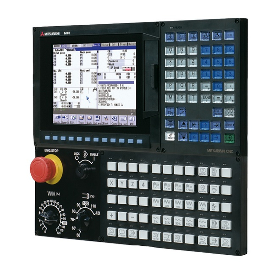
M700VS Series Setup Manual 1.2 Hardware Configuration 1.2 Hardware Configuration The following shows the hardware names used in this manual. (A) Cancel key (B) Menu changeover key (C) CF card interface on front of display unit (D) INPUT key (A) Rotary switch 1... -
Page 21: Flow Of Initial Setup
MITSUBISHI CNC 1 Setup Outline 1.3 Flow of Initial Setup The following flow chart shows the procedures of the initial setup. (Note) When setting up with backup files, refer to the section of "Data Backup and Restoration". WARNING Do not cancel the emergency stop before confirming the basic operation. Start Confirming the connection between control unit and peripheral devices... -
Page 22: Connecting And Setting The Hardware
Connecting and Setting the Hardware... -
Page 23: Connecting And Setting The Drive Unit
MITSUBISHI CNC 2 Connecting and Setting the Hardware 2.1 Connecting and Setting the Drive Unit 2.1.1 Connecting with Servo Drive Unit Connect the optical communication cables from the NC to the each drive unit so that they run in a straight line from the NC to the drive unit that is a final axis. -
Page 24: Connecting With Mds-D/Dh Series
M700VS Series Setup Manual 2.1 Connecting and Setting the Drive Unit 2.1.1.1 Connecting with MDS-D/DH Series Connect the NC and the drive units by the optical communication cables. The distance between the NC and the final drive unit must be within 30m and the bending radius within CAUTION 80mm. - Page 25 MITSUBISHI CNC 2 Connecting and Setting the Hardware (2) When using two or more power supply units within a single NC communication bus system Two or more power supply units may be required within a single NC communication bus system if the spindle drive unit capacity is large.
- Page 26 M700VS Series Setup Manual 2.1 Connecting and Setting the Drive Unit (3) When using one power supply shared unit by two NC communication bus systems In systems employing a number of small-capacity drive units, a single power supply unit can be shared by two NC communication bus systems.
-
Page 27: Connecting With Mds-Dm Series
MITSUBISHI CNC 2 Connecting and Setting the Hardware 2.1.1.2 Connecting with MDS-DM Series Connect the NC and the drive units by the optical communication cables. The distance between the NC and the final drive unit must be within 30m and the bending radius within CAUTION 80mm. - Page 28 M700VS Series Setup Manual 2.1 Connecting and Setting the Drive Unit (b) When using two or more power supply units within a single NC communication bus system Two or more power supply units may be required within a single NC communication bus system if the spindle drive unit capacity is large.
- Page 29 MITSUBISHI CNC 2 Connecting and Setting the Hardware (c) When using one power supply shared unit by two NC communication bus systems In systems employing a number of small-capacity drive units, a single power supply unit can be shared by two NC communication bus systems.
- Page 30 M700VS Series Setup Manual 2.1 Connecting and Setting the Drive Unit (2) Connecting the MDS-DM-SPV Series (a) When using only MDS-DM-SPV Series MDS-DM-SPV3F Spindle:1st axis Servo:2nd/3rd/4th axis Connected to the NC Optical communication cable (b) When using the MDS-D unit together...
- Page 31 MITSUBISHI CNC 2 Connecting and Setting the Hardware (c) When using one power supply shared unit by two NC communication bus systems MDS-D-V2 MDS-D-V2 9th/10th axis 11th/12th axis (CV control axis) Connected to the NC (2nd part system) Optical communication cable MDS-DM-V3 MDS-D-SP...
-
Page 32: Connecting With Mds-Svj3/Spj3 Series
M700VS Series Setup Manual 2.1 Connecting and Setting the Drive Unit 2.1.1.3 Connecting with MDS-SVJ3/SPJ3 Series Connect the NC and the drive units by the optical communication cables. The bending radius CAUTION must be within 50mm. Axis Nos. are determined by the rotary switch for setting the axis No. (Refer to the MDS-SVJ3/ SPJ3 Series Instruction Manual.) The axis No. -
Page 33: Setting The Rotary And Dip Switches
MITSUBISHI CNC 2 Connecting and Setting the Hardware 2.2 Setting the Rotary and DIP Switches 2.2.1 MDS-D/DH Series (1) Setting the rotary switch Set the axis number with the rotary switch. 1-axis 2-axis 1-axis 2-axis Power supply un it Servo drive unit Servo drive unit spindle drive unit spindle drive unit... - Page 34 M700VS Series Setup Manual 2.2 Setting the Rotary and DIP Switches (2) Setting the DIP switch As a standard setting, turn the all DIP switches OFF. The switches are OFF when facing bottom as illustrated. Turning these switches ON sets the corresponding axis to the unused axis.
-
Page 35: Mds-Dm Series
MITSUBISHI CNC 2 Connecting and Setting the Hardware 2.2.2 MDS-DM Series <MDS-DM-V3 Series> (1) Rotary switch settings Before turning on the power, the axis No. must be set with the rotary switch. The rotary switch settings will be validated when the drive units are turned ON. 3-axis Servo drive unit Spindle drive unit... - Page 36 M700VS Series Setup Manual 2.2 Setting the Rotary and DIP Switches (2) Setting the DIP switch As a standard setting, turn the all DIP switches OFF. The switches are OFF when facing bottom as illustrated. Turning these switches ON sets the corresponding axis to the unused axis.
-
Page 37: Mds-D-Svj3/Spj3 Series
MITSUBISHI CNC 2 Connecting and Setting the Hardware 2.2.3 MDS-D-SVJ3/SPJ3 Series Set the axis number with the rotary switch. MDS-D-SVJ3 MDS-D-SPJ3 7 9 8 8 6 A 7 9 6 A 5 B 5 B 4 C 4 C 3 D 3 D 2 E 2 E 1 F 1 F 0 0 ... -
Page 38: Connecting The Batteries
M700VS Series Setup Manual 2.3 Connecting the Batteries 2.3 Connecting the Batteries 2.3.1 Control Unit Battery The battery is not connected when the machine is delivered. Be sure to connect the battery before starting up. A lithium battery in the control unit battery holder retains parameter settings, machining programs and the like, which requires to be backed up at the power OFF. -
Page 39: Servo Drive Unit Battery
MITSUBISHI CNC 2 Connecting and Setting the Hardware 2.3.2 Servo Drive Unit Battery (Note) The battery connection is not necessary unless the drive unit employs absolute position detection. (Spindle drive unit does not require the battery, because the unit does not employ absolute position detection.) MDS-D/DH-V1/V2 and MDS-DM-V3 Connect the battery connector to the connector of the drive unit. - Page 40 M700VS Series Setup Manual 2.3 Connecting the Batteries MDS-DM-SPV2/SPV3 Connect the battery connector to the connector of the drive unit. Battery connector connection part magnified figure Battery Battery connector Connect the cell battery with BT1. To battery holder Connector for...
-
Page 41: Connecting And Setting The Remote I/O Unit
MITSUBISHI CNC 2 Connecting and Setting the Hardware 2.4 Connecting and Setting the Remote I/O Unit 2.4.1 Outline of the Remote I/O Unit There are eight types of remote I/O unit (FCUA-DX***): DX10*, DX11*, DX12* and DX14* (* is "0" or "1"). Specifications are different as shown below. - Page 42 M700VS Series Setup Manual 2.4 Connecting and Setting the Remote I/O Unit Bottom (A) RIO1 (From controller) (B) RIO2 (To terminating resister or to next RIO unit) (C) DCIN (24VDC input) Number of Machine control signals that can be Unit type...
-
Page 43: Connection And Station No. Setting On Remote I/O Unit
MITSUBISHI CNC 2 Connecting and Setting the Hardware 2.4.2 Connection and Station No. Setting on Remote I/O Unit When connecting directly to the control unit Control unit FCU7-MU531/ FCU7-MU541/ FCU7-MA541 Remote I/O unit FCUA-DX1** Station No.1 - 8 RIO1 CG72 Remote I/O 1ch FCUA-R211/SH41 Max. - Page 44 M700VS Series Setup Manual 2.4 Connecting and Setting the Remote I/O Unit When connecting to the operation panel I/O unit Control unit FCU7-MU531/ FCU7-MU541/ FCU7-MA541 Remote I/O unit Operation panel I/O unit FCUA-DX1** FCU7-DX710/711 Occupies Station No.3 - 6 the station No. 1, 2, 7, 8...
-
Page 45: Station No. Setting When Using Multiple Remote I/O Units
MITSUBISHI CNC 2 Connecting and Setting the Hardware 2.4.3 Station No. Setting when Using Multiple Remote I/O Units Multiple remote I/O units can be used, as long as the total No. of occupied stations connected with serial links is eight or less. (three/four or less when connected to the operation panel I/O unit). Unit type Number of occupied stations FCUA-DX10*... - Page 46 M700VS Series Setup Manual 2.4 Connecting and Setting the Remote I/O Unit Setting example 3 FCUA-DX110/111 or FCUA-DX120/121 Number of occupied stations: 2 Total number of occupied stations: 8 (Maximum configuration)
- Page 47 MITSUBISHI CNC 2 Connecting and Setting the Hardware When connecting to the operation panel I/O unit Station No. 1, 2, 7, 8 (or 1, 2, 3, 7, 8) are occupied by the operation panel I/O unit. (Station No. 7 and 8 are reserved for manual pulse generator.) The maximum numbers of stations and I/O points assigned to remote I/O unit(s) via RIO3 are as follows.
- Page 48 M700VS Series Setup Manual 2.4 Connecting and Setting the Remote I/O Unit Setting example 3 FCU7-DX720/721 FCUA-DX110/111 /730/731 or FCUA-DX100/101 FCUA-DX120/121 + + Number of occupied stations: 1 Total number of occupied stations: 3 (Maximum configuration)
-
Page 49: Device No. Assignment
MITSUBISHI CNC 2 Connecting and Setting the Hardware 2.4.4 Device No. Assignment The devices used by the PLC are determined as follows after the station Nos. are set with the rotary switches. Device No. read in Output device No. Analog output (AO) Rotary switch No. - Page 50 M700VS Series Setup Manual 2.4 Connecting and Setting the Remote I/O Unit (Note) When the analog output is equipped to several RIO channels, maximum of four RIO channels will be valid in the following order of priority. (1) RIO channel 1, (2) RIO channel 2, (3) RIO channel 3 (Ex.)
-
Page 51: Initializing The Nc Internal Data (Sram)
MITSUBISHI CNC 2 Connecting and Setting the Hardware 2.5 Initializing the NC Internal Data (SRAM) The initialization does not affect the settings of the option parameters. (1) With the NC power OFF, turn the left rotary switch (RSW1) to "0" and the right rotary switch (RSW2) to "C". Then, turn the power ON. -
Page 52: Setting Up With M70/M700 Setup Installer
Setting Up with M70/M700 SETUP INSTALLER... - Page 53 MITSUBISHI CNC 3 Setting Up with M70/M700 SETUP INSTALLER (Note) M70/M700 SETUP INSTALLER is used to install language data other than Japanese and English, as well as custom screens. If you do not need the installation, go to the next section. You can install the following data with M70/M700 SETUP INSTALLER.
-
Page 54: Compatible Data And Folder Configuration In The Cf Card
M700VS Series Setup Manual 3.1 Compatible Data and Folder Configuration in the CF Card 3.1 Compatible Data and Folder Configuration in the CF Card (1) M70/M700 SETUP INSTALLER compatible data Type Data Details Remarks lang0_xxx.bin Language data (for FROM) Language... - Page 55 MITSUBISHI CNC 3 Setting Up with M70/M700 SETUP INSTALLER (2) Folder configuration in the CF card The following shows the folder configuration of the M70/M700 SETUP INSTALLER compatible data which is stored in the CF card. CF Card Lang (language data folder) A0 (folder labeled by version) lang0_jpn.bin (Japanese language data for FROM) A1 (folder labeled by version)
-
Page 56: Operation Procedure
M700VS Series Setup Manual 3.2 Operation Procedure 3.2 Operation Procedure 3.2.1 Starting Up M70/M700 SETUP INSTALLER (1) Insert the M70/M700 SETUP INSTALLER CF card into the card interface on front of display unit. (2) Turn the power ON while pressing the cancel key The M70 SETUP INSTALLER Mode Select screen will appear in about 15 seconds after the startup screen appears. - Page 57 MITSUBISHI CNC 3 Setting Up with M70/M700 SETUP INSTALLER (2) Select the language to install with the menu key. The language selected is shown in the "Now Selected Language" field. (Note 1) To change the selected language, press [Clear] before selecting again. (Note 2) The 2nd language can be selected when the expansion FROM is provided.
-
Page 58: Installing Custom Data
M700VS Series Setup Manual 3.2 Operation Procedure 3.2.3 Installing Custom Data (1) Select [Custom Data] on the Mode Select screen to switch to the Custom Data Install screen. (2) Select [Install]. (3) A confirmation message appears. Select [Yes] to start the installation. -
Page 59: Uninstalling Custom Data
MITSUBISHI CNC 3 Setting Up with M70/M700 SETUP INSTALLER 3.2.4 Uninstalling Custom Data (1) Select [Uninst] on the Custom Data Install screen. (2) A confirmation message appears. Select [Yes] to start the uninstallation. (Note 1) Selecting [No] displays the previous menus. (Note 2) Do not turn the power OFF during the uninstallation. -
Page 60: Installing Custom Startup Screen
M700VS Series Setup Manual 3.2 Operation Procedure 3.2.5 Installing Custom Startup Screen (1) Select [Custom StartUp] on the Mode Select screen to switch to the Custom Startup Screen Install screen. (2) Select [Install]. (3) A confirmation message appears. Select [Yes] to start the installation. -
Page 61: Uninstalling Custom Startup Screen
MITSUBISHI CNC 3 Setting Up with M70/M700 SETUP INSTALLER 3.2.6 Uninstalling Custom Startup Screen (1) Select [Uninst] on the Custom Startup Screen Install screen. (2) A confirmation message appears. Select [Yes] to start the uninstallation. (3) A message appears when the uninstallation has been completed. (Note 1) Selecting [No] displays the previous menus. -
Page 62: List Of Error Messages
M700VS Series Setup Manual 3.3 List of Error Messages 3.3 List of Error Messages Message Details The first language has not been selected at the installation of The 1st language is not selected. language pack. Specify the first language again. - Page 63 MITSUBISHI CNC 3 Setting Up with M70/M700 SETUP INSTALLER...
-
Page 64: Setting The Parameters And Date/Time
Setting the Parameters and Date/Time... -
Page 65: Selecting The Nc System Type
MITSUBISHI CNC 4 Setting the Parameters and Date/Time Confirm the emergency stop state before carrying out the steps in this chapter. WARNING 4.1 Selecting the NC System Type When employing the lathe system, set the parameter as follows. (1) On the Mainte screen, select [Mainte] and then [Psswd input]. Enter "MPARA"... -
Page 66: Setting On The System Setup Screen
M700VS Series Setup Manual 4.2 Setting on the System Setup Screen 4.2 Setting on the System Setup Screen Set the following items on the system setup screen. Displayed language and the number of spindle connections Number of axes and command type for each part system... - Page 67 MITSUBISHI CNC 4 Setting the Parameters and Date/Time (3) Carry out the spindle and servo axis settings. Set the following items. Common setting Number of spindles: Set the number of spindles connected to the NC. This setting is registered at "#1039 spinno (Number of spindles)".
- Page 68 M700VS Series Setup Manual 4.2 Setting on the System Setup Screen Setting example (with three servo axes and a spindle) Y axis Power supply unit X axis Z axis Spindle...
- Page 69 MITSUBISHI CNC 4 Setting the Parameters and Date/Time (5) Write the parameter settings and format the system. (a) Select [Param setting]. (b) The message "Set up parameter? (Y/N)" appears. Press "Y". The message "Param set ended. Format NC memory? (Y/N)" appears. Press "Y". (d) The message "Format complete"...
-
Page 70: Setting The Parameters For The Machine Specifications
M700VS Series Setup Manual 4.3 Setting the Parameters for the Machine Specifications 4.3 Setting the Parameters for the Machine Specifications (1) On the Mainte screen, select [Mainte] and then [Psswd input]. Enter "MPARA" in the setting area and press the INPUT key. - Page 71 MITSUBISHI CNC 4 Setting the Parameters and Date/Time (Note 1) These parameters are not set on the system setup screen. Use the parameter screen to set them. (Note 2) Refer to the section of "Explanation of Parameters" for the details of the parameters. You can also refer to the parameter guidance display.
-
Page 72: Setting Date And Time
M700VS Series Setup Manual 4.4 Setting Date and Time 4.4 Setting Date and Time (1) Select [Time] on the Monitr screen. (2) Select [Time setting] on the integrated time screen. The time setting mode is entered. The cursor appears at the "#1 Date" position in the Run-out time display. - Page 73 MITSUBISHI CNC 4 Setting the Parameters and Date/Time...
-
Page 74: Plc Program Writing
PLC Program Writing... -
Page 75: Setting The Ethernet Communication
MITSUBISHI CNC 5 PLC Program Writing In this manual, PLC program writing is executed by connecting a personal computer, which has GX Developer installed, to the control unit. You can also save the PLC program in a CF card and write the data to NC using the external file operations on PLC onboard. -
Page 76: Connecting The Control Unit And A Personal Computer
M700VS Series Setup Manual 5.2 Connecting the Control Unit and a Personal Computer (5) Set the following addresses. IP address: 192.168.200.2 Subnet mask: 255.255.255.0 (6) Click "OK" and close all the windows. 5.2 Connecting the Control Unit and a Personal Computer Connect a personal computer, which has GX Developer installed, to the control unit. -
Page 77: Setting The Communication With Gx Developer
MITSUBISHI CNC 5 PLC Program Writing 5.3 Setting the Communication with GX Developer (1) Start GX Developer on the personal computer. Open a created project. (2) Select [Transfer setup...] from the [Online] menu. (3) On the "Transfer Setup" screen, click "Ethernet board" in the "PC side I/F" field and double-click "Ethernet module" in the "PLC side I/F"... - Page 78 M700VS Series Setup Manual 5.3 Setting the Communication with GX Developer (5) Click "Other station(Single network)" in the "Other station" field on the "Transfer Setup" screen. (6) Click "Connection test" to execute the test. After confirming the message "Successfully connected", click "OK".
-
Page 79: Setting The Parameters On Gx Developer
MITSUBISHI CNC 5 PLC Program Writing 5.4 Setting the Parameters on GX Developer (1) Double-click on [Parameter] --> [PLC parameter] in the project list on GX Developer. The "QnA Parameter" dialog box appears. (2) On the "Device" tab, confirm the followings are set. Inside relay M: 10K Retentive timer ST: 64 (Do not attach "K") Confirm the other parameter settings. - Page 80 M700VS Series Setup Manual 5.4 Setting the Parameters on GX Developer (3) Check the "Allow" check box in the "Remote reset" field on the "PLC system" tab. Click "End".
-
Page 81: Writing A Plc Program With Gx Developer
MITSUBISHI CNC 5 PLC Program Writing 5.5 Writing a PLC Program with GX Developer (1) Select [Write to PLC...] from the [Online] menu. (2) Check all the check boxes in the "Write to PLC" dialog box, and then click "Execute". (3) GX Developer starts the PLC program writing. -
Page 82: Writing A Plc Program To Rom With Gx Developer
M700VS Series Setup Manual 5.6 Writing a PLC Program to ROM with GX Developer 5.6 Writing a PLC Program to ROM with GX Developer (1) Select [Remote operation...] from the [Online] menu. (2) Select "STOP" from the pull-down menu in the "Operation" field in the "Remote operation" dialog box. Click... - Page 83 MITSUBISHI CNC 5 PLC Program Writing (3) Select [Remote operation] again. Select "PAUSE" from the pull-down menu in the "Operation" field and click "Execute". (Executing "PAUSE" starts the writing to NC ROM.) (4) The message "Completed." appears when the writing to ROM is completed. (Note) The program has been written to ROM although the on-board screen still shows the message "ROM- Write incomplete".
-
Page 84: Setting The Plc Parameters
M700VS Series Setup Manual 5.7 Setting the PLC Parameters 5.7 Setting the PLC Parameters Select [Bit select] on the Mainte screen and set the bit selection parameters from #6449 to #6452. See the following table for details of the parameters. - Page 85 MITSUBISHI CNC 5 PLC Program Writing...
-
Page 86: Confirming The Basic Operation
Confirming the Basic Operation... -
Page 87: Checking Inputs/Outputs And Alarms
MITSUBISHI CNC 6 Confirming the Basic Operation 6.1 Checking Inputs/Outputs and Alarms (1) Checking the input signals (a) Select [I/F dia] on the Diagn screen. (b) Confirm that signals turn ON/OFF properly on the IF Diagnosis screen. (2) Checking the alarm display (a) Select [Alarm message] on the Diagn screen. -
Page 88: Confirming Manual Operation
M700VS Series Setup Manual 6.2 Confirming Manual Operation 6.2 Confirming Manual Operation 6.2.1 Using the Manual Pulse Generator (1) Select the handle mode. (2) Set the handle feed magnification to a minimum value. (3) Cancel the emergency stop. Confirm the READY lamp is ON on the keyboard. -
Page 89: Servo Simplified Adjustment
MITSUBISHI CNC 6 Confirming the Basic Operation 6.2.3 Servo Simplified Adjustment 6.2.3.1 First Measure Against Vibration Setting the filter can reduce the vibration. (1) Select [Drv mon] and then [Servo unit] on the Diagn screen. See the displayed value in "AFLT frequency". (Note) The screen above is when NC parameters have default values. -
Page 90: Outline Of Ms Configurator
M700VS Series Setup Manual 6.2 Confirming Manual Operation 6.2.3.2 Outline of MS Configurator With MS Configurator, the attribute of the servo motor system is measured and the bode diagram is output by activating the motor with vibration signals and measuring/analyzing the machine characteristics. And the servo waveform measurement function is supported, too. - Page 91 MITSUBISHI CNC 6 Confirming the Basic Operation...
-
Page 92: Setting The Position Detection System
Setting the Position Detection System... -
Page 93: Adjusting The Absolute Position Detection System
MITSUBISHI CNC 7 Setting the Position Detection System There are two kinds of position detection system: one is "relative position detection", which establishes the reference position (zero point) at every CNC power-ON; the other is "absolute position detection", which allows to start the operation without establishing the reference position (zero point) again after the CNC power-ON. -
Page 94: Marked Aligment Method I
M700VS Series Setup Manual 7.1 Adjusting the Absolute Position Detection System (4) Dog method This method requires a dog sensor. Move the table until the dog is kicked, and the first grid point after the dog OFF is determined as the basic position. -
Page 95: Marked Point Alignment Method Ii
MITSUBISHI CNC 7 Setting the Position Detection System 7.1.2 Marked Point Alignment Method II This is a method to align to the marked point (matchmark or marking line) on the machine. (1) Select [Param] on the Mainte screen, then select [Abs pos param]. On the absolute position parameter screen, set "#2049 type (Absolute position detection method)"... -
Page 96: Other Setting Method
M700VS Series Setup Manual 7.1 Adjusting the Absolute Position Detection System 7.1.3 Other Setting Method 7.1.3.1 Machine End Stopper Method: Automatic Initialization (1) Select [Param] -> [Abs.Posit.Param.] in the maintenance screen. Set the following parameters in the "Abs.Posit.Param." screen. Parameter... - Page 97 MITSUBISHI CNC 7 Setting the Position Detection System (8) Start JOG operation. The axis moves automatically as follow. The axis moves toward the machine end stopper at the push speed. (a in the diagram). The axis pushes against the machine end stopper. After the current reached its limit continually during given time period, the axis returns toward the approach point at the "push speed".
- Page 98 M700VS Series Setup Manual 7.1 Adjusting the Absolute Position Detection System (Note 1) To change just the basic machine coordinate zero point, set "#0 Absolute posn set" and "#2 Zero-P", and then turn the power OFF and ON. (Note 2) If pressing against the machine end is attempted without passing the grip point once after turning the power ON, the operation message "Not passed on grid"...
-
Page 99: Machine End Stopper Method: Manual Initialization
MITSUBISHI CNC 7 Setting the Position Detection System 7.1.3.2 Machine End Stopper Method: Manual Initialization (1) Select [Param] -> [Abs.Posit.Param.] in the maintenance screen. Set the following parameters in the "Abs.Posit.Param." screen. Parameter Setting value 1 (machine end stopper method is #2049 type (absolute position detection type) selected) #2054 clpush (current limit) -
Page 100: Dog-Type
M700VS Series Setup Manual 7.1 Adjusting the Absolute Position Detection System 7.1.3.3 Dog-type (1) Select [Param] -> [Abs.Posit.Param.] in the maintenance screen. Set "3" for the axis for which the absolute position initialization is performed to "#2049 type (absolute position detection type)". -
Page 101: Precautions
MITSUBISHI CNC 7 Setting the Position Detection System 7.1.4 Precautions 7.1.4.1 Precautions common for the initilization operation (1) The "#0 Absolute posn set" parameter (axis for which zero point is to be initialized) can be set simultaneously for all axes or individually for each axis. (2) The "#0 Absolute posn set"... - Page 102 M700VS Series Setup Manual 7.1 Adjusting the Absolute Position Detection System (2) Setting the reference position The reference position can be set as shown below by setting the "#2037 G53ofs". Absolute position Reference "G53ofs" = 0 origin point position (Example 1) To set the reference...
-
Page 103: Adjustment Of Reference Position Return In Relative Position Detection System
MITSUBISHI CNC 7 Setting the Position Detection System 7.2 Adjustment of Reference Position Return in Relative Position Detection System 7.2.1 Dog-type Reference Position Return 7.2.1.1 Dog-type Reference Position Return Operation In the dog-type reference position return, the axis moves as follows: (1) Starts moving at G28 rapid traverse rate. -
Page 104: Dog-Type Reference Position Return Adjustment Procedures
M700VS Series Setup Manual 7.2 Adjustment of Reference Position Return in Relative Position Detection System 7.2.1.2 Dog-type Reference Position Return Adjustment Procedures Adjust the dog-type reference position return with the following steps. (1) Select [Param] menu from the maintenance screen, and then select zero point parameter screen by feeding the page. - Page 105 MITSUBISHI CNC 7 Setting the Position Detection System (5) Determine the grid mask amount according to the state as shown below. Grid space When is smaller Axis speed Electrical zero point (the first grid after the switch is turned ON and OFF) than the grid amount Reference position Position...
- Page 106 M700VS Series Setup Manual 7.2 Adjustment of Reference Position Return in Relative Position Detection System (7) Turn the power OFF and ON, and then execute reference position return. (8) Confirm the grid space and grid amount values on DRIVE MONITOR screen.
- Page 107 MITSUBISHI CNC 7 Setting the Position Detection System Grid point The position detector has a Z-phase that generates one pulse per rotation. The 0-point position of this Z-phase is the grid point. Thus, there is a grid point per rotation of the position detector, and the machine has many grid points at a regular pitch. The grid point can be set at intervals of grid space by setting the grid space (#2029 grspc).
- Page 108 M700VS Series Setup Manual 7.2 Adjustment of Reference Position Return in Relative Position Detection System Reference position return direction (#2030 dir (-)) The direction of the (axis) movement, after the dog-type reference position return is executed and the limit switch kicks the dog and decelerate to stop, is set to either positive "0"...
- Page 109 MITSUBISHI CNC 7 Setting the Position Detection System...
-
Page 110: Setting The Tool Entry Prohibited Range
Setting the Tool Entry Prohibited Range... -
Page 111: Stroke End (H/W Ot)
MITSUBISHI CNC 8 Setting the Tool Entry Prohibited Range Following functions are available for setting a tool entry prohibited range to detect over travels (OT). (1) Stroke end (H/W OT) The limit switch signal will detect the stroke end and limit the movement of the axis. (2) Stored stroke limit (S/W OT) Prohibited ranges are set with parameters. -
Page 112: Stored Stroke Limit (S/W Ot)
M700VS Series Setup Manual 8.2 Stored stroke limit (S/W OT) 8.2 Stored stroke limit (S/W OT) 8.2.1 Outline Three tool entry prohibited ranges can be set with stored stroke limit I, stored stroke limit II, IIB and stored stroke limit IB. - Page 113 MITSUBISHI CNC 8 Setting the Tool Entry Prohibited Range Valid Conditions of Stored Stroke Limit When using the relative position detection system, the stored stroke limit is invalid until the reference position return is completed after the power is turned ON. The stored stroke limit can be validated even if the reference position return is not yet completed, by setting "#2049 type (Absolute position detection method)"...
-
Page 114: Detailed Explanation
M700VS Series Setup Manual 8.2 Stored stroke limit (S/W OT) 8.2.2 Detailed Explanation The stored stroke limit sets a prohibited range with the parameters or program command. The minimum and maximum values of the prohibited range are set as the coordinate value (radius value) on the machine coordinate system for each axis. -
Page 115: Stored Stroke Limit I
MITSUBISHI CNC 8 Setting the Tool Entry Prohibited Range 8.2.2.1 Stored Stroke Limit I This is a stroke limit function used by the machine tool builder. The boundary is set with the parameters ("#2013 OT - (Soft limit I -)" and "#2014 OT + (Soft limit I +)"). The outside of the set boundary is the prohibited range. The outside of the set boundary is the prohibited range. -
Page 116: Stored Stroke Limit Ii
M700VS Series Setup Manual 8.2 Stored stroke limit (S/W OT) 8.2.2.2 Stored Stroke Limit II The boundary is set with the axis parameters "#8204 OT-CHECK-N" and "#8205 OT-CHECK-P" or with program commands. Either the inside or the outside of the set boundary is the prohibited range. Whether the inside or outside of the range is prohibited is determined by "#8210 OT-INSIDE". - Page 117 MITSUBISHI CNC 8 Setting the Tool Entry Prohibited Range (2) Stored stroke limit IIB (When prohibited range is on inside) A range except for that of the stored stroke limit I becomes the movement prohibited range. : Moveable range : Prohibited range (A): Set value for (-) side (B): Set value for (+) side (C): Prohibited range by stored stroke limit IIB...
-
Page 118: Stored Stroke Limit Ib
M700VS Series Setup Manual 8.2 Stored stroke limit (S/W OT) 8.2.2.3 Stored Stroke Limit IB The boundary is set for each axis with the axis parameters "#2061 OT_1B-" and "#2062 OT_1B+". The inside of the set boundary is the prohibited range. -
Page 119: Stored Stroke Limit Ic
MITSUBISHI CNC 8 Setting the Tool Entry Prohibited Range 8.2.2.4 Stored Stroke Limit IC The boundary is set for each axis with the axis parameters "#2061 OT_1B-" and "#2062 OT_1B+". The inside of the set boundary is the machine movement valid range. This is valid when the axis parameter "#2063 OT_1Btype (Soft limit IB type)"... -
Page 120: Movable Range During Inclined Axis Control
M700VS Series Setup Manual 8.2 Stored stroke limit (S/W OT) 8.2.2.5 Movable Range during Inclined Axis Control By setting "#2063 OT_1Btype" to "3", the inclined axis control axis can be checked with the program coordinates using the stored stroke limit IB/IC range setting ("#2061" and "#2062"). The stored stroke limit IB and IC cannot be used together at this time. -
Page 121: Stored Stroke Limit For Rotation Axis
MITSUBISHI CNC 8 Setting the Tool Entry Prohibited Range 8.2.2.6 Stored Stroke Limit for Rotation Axis Stored stroke limits I and II are used as the stored stroke limit for the rotation axis. The area between the maximum and minimum values of the prohibited range's parameters, which does not contain the 0 point of the basic machine coordinate system, is the entry prohibited range. -
Page 122: Confirming The Spindle Operation
Confirming the Spindle Operation... -
Page 123: In Manual Operation (With Manual Numerical Command)
MITSUBISHI CNC 9 Confirming the Spindle Operation Confirm that the spindle operates properly in manual/MDI operation. Confirm the spindle rotation speed as well. 1. Do not adjust the spindle when possible risks associated with adjustment procedures are CAUTION not thoroughly taken into consideration. 2. -
Page 124: In Mdi Operation
M700VS Series Setup Manual 9.2 In MDI Operation 9.2 In MDI Operation (1) Select MDI mode. (2) Select [MDI] on the Setup screen. Enter a program to issue an S command. Program example (to rotate the spindle at 100r/min for 5 seconds) S100 M03 ;... - Page 125 MITSUBISHI CNC 9 Confirming the Spindle Operation...
-
Page 126: Setting The Deceleration Check
Setting the Deceleration Check... -
Page 127: Function
MITSUBISHI CNC 10 Setting the Deceleration Check 10.1 Function The purpose of the deceleration check is to reduce the machine shock that occurs when the control axis feedrate is suddenly changed, and prevent corner roundness. The check is carried out at block joints. (1) Deceleration check during rapid traverse The deceleration check is always carried out at the block joints (before executing the next block) during rapid traverse. -
Page 128: Deceleration Check Method
M700VS Series Setup Manual 10.2 Deceleration Check Method 10.2 Deceleration Check Method (1) Command deceleration check After interpolation for one block has been completed, the completion of the command system deceleration is confirmed before execution of the next block. The time required for the deceleration check is determined according to the acceleration/deceleration mode and acceleration/deceleration time constant. - Page 129 MITSUBISHI CNC 10 Setting the Deceleration Check (2) In-position check When the in-position check is valid, the command deceleration check is carried out. After that, it is confirmed that the servo system positional error is less than the parameter setting value, and the next block is executed. The in-position check width can be designated with the servo parameter in-position width (SV024).
-
Page 130: Deceleration Check For Opposite Direction Movement Reversal
M700VS Series Setup Manual 10.3 Deceleration Check for Opposite Direction Movement Reversal 10.3 Deceleration Check for Opposite Direction Movement Reversal Deceleration check cannot be designated for G1 -> G0 or G1 -> G1, but it can be designated in the following manner only when the movement reverses to the opposite direction in successive blocks. -
Page 131: Parameter
MITSUBISHI CNC 10 Setting the Deceleration Check 10.4 Parameter (1) Designating deceleration check Base specification parameter Item Details Setting range The definitions are changed with the setting of "#1306 InpsTyp 1193 inpos Deceleration check specification type". When Select the deceleration check method for G0. Deceleration 0: Command deceleration check 0 / 1... - Page 132 M700VS Series Setup Manual 10.4 Parameter (3) Designation of in-position check width (a) Servo parameter Item Details Setting range Set the in-position detection width. Set the accuracy required for the machine. SV024 In-position The lower the setting is, the higher the positioning 2224 0 to 32767 (μm)
-
Page 133: Precautions
MITSUBISHI CNC 10 Setting the Deceleration Check 10.5 Precautions (1) Designating deceleration check When in-position check is valid, set the in-position width in the servo parameters. (2) Deceleration check for opposite direction movement reversal When deceleration check is valid (G0Ipfg=1), deceleration check will be executed when the axis reverses its movement to the opposite direction at the G1 ->... -
Page 134: Data Backup And Restoration
Data Backup and Restoration... -
Page 135: All Backup
The following devices are available in all backup and restoration. M700VW Series: DS, Memory card (CF card or USB memory), and hard disk (HD) M700VS Series: Memory card (CF card) and USB memory Files to be backed up/ restored are as follows. - Page 136 M700VS Series Setup Manual 11.1 All Backup (5) The all backup screen appears. "Device" shows the backup destination. To change the destination, click [Device select] and select the device. (6) Select [Backup].
- Page 137 MITSUBISHI CNC 11 Data Backup and Restoration (7) The menu is highlighted. The operation message "Select directory to backup" appears. Select the backup destination ("Manual" or "Master data") in the backup list. Then press the INPUT key. (Note) "Backup list" shows the list of backup destination directories and backup dates/times (year, month, date and hour).
-
Page 138: All Restoration
M700VS Series Setup Manual 11.2 All Restoration 11.2 All Restoration (1) Carry out the emergency stop. (2) Insert the CF card containing the backed up data into the interface on front of display unit. (Note) When M700VW Series is used, an adapter is required to insert a CF card into the interface on front of display unit. - Page 139 MITSUBISHI CNC 11 Data Backup and Restoration (5) Select [Restore]. (6) The menu is highlighted. The operation message "Select directory to restore" appears. Move the cursor to select the area. Press the INPUT key. (7) The operation message "OK? (Y/N)" appears. Press Y or INPUT key to start the restore. (8) The operation message "Restoring"...
-
Page 140: Hardware Replacement Methods
Hardware Replacement Methods... -
Page 141: Durable Parts
MITSUBISHI CNC 12 Hardware Replacement Methods 12.1 Durable Parts [List of durable parts] Durable parts Part type Control unit battery Q6BAT Backlight for FCU7-DU120-11 84LHS06 Backlight for FCU7-DU140-11/31 104LHS52 Touch Panel Protective Sheet for FCU7-DU140-31 N939B036G51 Key sheet for FCU7-KB024/44 N330B532G51 Key sheet for FCU7-KB029 N330A565G51... - Page 142 M700VS Series Setup Manual 12.1 Durable Parts Battery cover Battery holder Battery connector [Precautions for handling battery] (1) Always replace the battery with the same type. (2) Do not disassemble the battery. (3) Do not place the battery in flames or water.
-
Page 143: Display Unit Cooling Fan
MITSUBISHI CNC 12 Hardware Replacement Methods 12.1.2 Display Unit Cooling Fan Type MMF-06G24DS-RP2 50,000 hours (When the rotary speed decreased 20% less than the initial Life values) (Note) The life is estimated on the assumption that it is used under 60°C environment. Keep in mind that the value above is not a guaranteed value. -
Page 144: Backlight
M700VS Series Setup Manual 12.1 Durable Parts 12.1.3 Backlight Display unit type Screen size TFT-LCD type Backlight type Inverter type FCU7-DU120-11 8.4-type NL6448BC21-09 84LHS06 84PW031 FCU7-DU140-11 10.4-type NL6448BC33-74N 104LHS52 104PW161 FCU7-DU140-31 Backlight life ... 50,000 hours (Duration of time until luminance drops to 50% of the initial value.) The life is estimated on the assumption that it is used under 25 ℃... - Page 145 MITSUBISHI CNC 12 Hardware Replacement Methods [8.4-type/10.4-type display unit] Backlight connector Backlight inverter Backlight...
-
Page 146: Fuse
M700VS Series Setup Manual 12.1 Durable Parts 12.1.4 Fuse 12.1.4.1 Control Unit Protection Fuse Disconnection of the protection fuse will be caused by misconnections such as a reverse connection of 24VDC power supply connector between +24V terminal and the ground. -
Page 147: Front Memory Interface Card
MITSUBISHI CNC 12 Hardware Replacement Methods 12.1.5 Front Memory Interface Card Replace the front memory interface card on which the connector CF has been broken due to a wrong insertion or repetitive insertions/removals of the CF card. [Replacement procedures] (1) Remove the control unit as described in the section of "Control Unit". (2) Remove the two screws which fix the front memory interface card. -
Page 148: Touch Panel Protective Sheet
M700VS Series Setup Manual 12.1 Durable Parts 12.1.6 Touch Panel Protective Sheet Type of 10.4-type touch panel protective sheet : N939B036G51 Type of 15-type touch panel protective sheet for M700VW Series: N939B060G61 (1) Remove the old protective sheet and clean the surface of the display unit. -
Page 149: Key Sheet
MITSUBISHI CNC 12 Hardware Replacement Methods 12.1.7 Key Sheet The key sheet covering the sheet-key type keyboard can be replaced. Remove the old key sheet as shown below, then place the new one. Key sheet for FCU7-KB024/44 N330B532G51 Key sheet for FCU7-KB029 N330A565G51 (Note1) Clean the surface before placing the new key sheet. -
Page 150: Control Unit
M700VS Series Setup Manual 12.2 Control Unit 12.2 Control Unit [Replacement procedures] Always replace the control unit with the machine power turned OFF. (1) Check that the machine power is turned OFF. (If the power is not OFF, turn it OFF.) (2) Disconnect all the external cables from the control unit. - Page 151 MITSUBISHI CNC 12 Hardware Replacement Methods (Note) Wire the control unit optical cable as shown below. Refer to the Connection Manual when handling and wiring optical communication cable. Control unit Recommended clamp material CKN-13SP KITAGAWA INDUSTRIES Optical communication cable (section with reinforced sheath): Bending radius: Refer to the specification of your optical communication cable.
-
Page 152: Installation On Fcu7-Du120-11 (8.4-Type)
M700VS Series Setup Manual 12.2 Control Unit 12.2.1 Installation on FCU7-DU120-11 (8.4-type) LCD cable G097 (with ferrite core) F480 cable 84PW031 + cover (Note) After mounting a new control unit, check the screen's brightness with a slide switch LCDSEL. -
Page 153: Installation On Fcu7-Du140-11/31 (10.4-Type)
MITSUBISHI CNC 12 Hardware Replacement Methods 12.2.2 Installation on FCU7-DU140-11/31 (10.4-type) LCD cable G492 (with ferrite core) Backlight cable G484 F480 cable 104PW161 + cover (Note) After mounting a new control unit, check the screen's brightness with a slide switch LCDSEL. Calibrate the touch panel when using it, referring to the section of "Calibration Setting and Confirmation". -
Page 154: Installation On Fcu7-Du140-31 (10.4-Type Touch Panel)
M700VS Series Setup Manual 12.2 Control Unit 12.2.3 Installation on FCU7-DU140-31 (10.4-type touch panel) TESTIN G422 (Note) Calibrate the touch panel, referring to the section of "Calibration Setting and Confirmation". -
Page 155: Calibration Setting And Confirmation
MITSUBISHI CNC 12 Hardware Replacement Methods 12.2.4 Calibration Setting and Confirmation The touch panel calibration is saved in the control unit. When only the control unit has been replaced, the calibration must be carried out again. (Note) Use a round-tip stick to set the position properly. Take care not to scratch the protective sheet covering the panel. - Page 156 M700VS Series Setup Manual 12.2 Control Unit (3) Keep pressing the center of the bottom-right cross with a red circle for more than one second. Then lift the stick off. When the data has been achieved, the bottom-right cross turns green.
- Page 157 MITSUBISHI CNC 12 Hardware Replacement Methods (5) After touching ten points, the display will show the result. <Result: NG> <Result: OK> Points which has resulted in NG will be shown in red. When the result shows "OK": The calibration settings have been successfully measured. Turn the right rotary switch (RSW2) back to "0", then turn the power ON again.
-
Page 158: Display Unit
M700VS Series Setup Manual 12.3 Display Unit 12.3 Display Unit [Replacement procedures] Always replace the display unit with the control unit (machine) power turned OFF. (1) Check that the machine power is turned OFF. (If the power is not OFF, turn it OFF.) (2) Open the electric cabinet door. -
Page 159: Keyboard Unit
MITSUBISHI CNC 12 Hardware Replacement Methods 12.4 Keyboard Unit [Replacement procedures] Always replace the keyboard unit with the control unit (machine) power turned OFF. (1) Check that the machine power is turned OFF. (If the power is not OFF, turn it OFF.) (2) Open the electric cabinet door. -
Page 160: Operation Panel I/O Unit
M700VS Series Setup Manual 12.5 Operation Panel I/O Unit 12.5 Operation Panel I/O Unit [Replacement procedures] Always replace the operation panel I/O unit with the control unit (machine) power turned OFF. (1) Check that the machine power is turned OFF. (If the power is not OFF, turn it OFF.) (2) Open the electric cabinet door. -
Page 161: Compactflash (Cf) Card
MITSUBISHI CNC 12 Hardware Replacement Methods 12.6 CompactFlash (CF) Card [Card insertion procedures] (1) Open the card interface door on the display unit right end. (2) Insert the CF card. (Insert it so that the top surface faces to the observer's right or display side.) [Card ejecting procedures] (1) Open the card interface door on the display unit right end. -
Page 162: Usb Memory
M700VS Series Setup Manual 12.7 USB Memory 12.7 USB Memory The USB memory slot is above the CF card interface. Open the door located on the display unit right end and insert/remove the USB memory. USB memory slot (Note) Do not remove a USB memory during the data reading/writing. - Page 163 MITSUBISHI CNC 12 Hardware Replacement Methods...
-
Page 164: Cables
Cables... -
Page 165: Precautions When Connecting/Disconnecting Cables
MITSUBISHI CNC 13 Cables 13.1 Precautions when Connecting/Disconnecting Cables If the cable is connected/disconnected without turning the power OFF, the normal unit or peripheral devices could be damaged, and risks could be imposed. Disconnect each cable with the following procedures. (a) For the following type of connector, press the tabs with a thumb and forefinger in the direction of the arrow, and pull the connector off. - Page 166 M700VS Series Setup Manual 13.1 Precautions when Connecting/Disconnecting Cables (b) For a flat cable type connector with latches, open the latches in the directions of the arrows, and pull the connector off. Open Pull (c) For a flat cable type connector without latches, hold the connector with a thumb and forefinger, and pull the connector off.
- Page 167 MITSUBISHI CNC 13 Cables (e) For the optical cable connector, pull off while holding down the lock button. Press Pull (f) For the Ethernet connector, pull off while holding down the locked latch. (1) Press Pull 1. Do not connect or disconnect the cables between units while the power is ON. CAUTION 2.
-
Page 168: Precautions For Using Optical Communication Cable
M700VS Series Setup Manual 13.2 Precautions for Using Optical Communication Cable 13.2 Precautions for Using Optical Communication Cable An optical communication cable is used for communication between the control unit and the drive unit. Special precautions, differing from the conventional cable, are required when laying and handling the optical communication cable. -
Page 169: Precautions For Laying Optical Communication Cable
MITSUBISHI CNC 13 Cables 13.2.3 Precautions for Laying Optical Communication Cable (1) Do not apply a force exceeding the cable's tolerable tension. Binding the cables too tight with tie-wraps could result in an increased loss or a disconnection. Use a cushioning material such as a sponge or rubber when bundling the cables and fix so that the cables do not move. -
Page 170: Appendix 1 Explanation Of Parameters
Appendix 1 A p p e n d i x 章 付録 Explanation of Parameters... -
Page 171: Appendix 1.1 User Parameters
MITSUBISHI CNC Appendix 1 Explanation of Parameters Appendix 1.1 User Parameters The parameters with "(PR)" requires the CNC to be turned OFF after the settings. Turn the power OFF and ON to enable the parameter settings. 【#8001】 WRK COUNT M Set the M code for counting the number of the workpiece repeated machining. - Page 172 M700VS Series Setup Manual Appendix 1.1 User Parameters 【#8009】 DSC. ZONE Set the position where deceleration starts at the corner. Designate at which length point before the corner deceleration should start. ---Setting range--- 0 to 99999.999 (mm) 【#8010】 ABS. MAX. (for L system only) Set the maximum value when inputting the tool wear compensation amount.
- Page 173 MITSUBISHI CNC Appendix 1 Explanation of Parameters 【#8017】 G71 DELTA-D (for L system only) Set the change amount of the rough cutting cycle. The rough cutting cycle (G71, G72) cutting amount repeats d+ ⊿ d, d, d- ⊿ d using the value (d) commanded with D as a reference.
- Page 174 M700VS Series Setup Manual Appendix 1.1 User Parameters 【#8020】 DCC ANGLE Set the minimum value of an angle (external angle) that should be assumed to be a corner. When an inter-block angle (external angle) in high-accuracy mode is larger than the set value, it will be determined as a corner and the speed will go down to sharpen the edge.
- Page 175 MITSUBISHI CNC Appendix 1 Explanation of Parameters 【#8023】 CURVE COMP Set the compensation coefficient to further reduce or increase the radius reduction amount at the curve (arc, involute, spline) during the high-accuracy control mode. Coefficient = 100 - setting value (Note) This is valid when "#8021 COMP CHANGE"...
- Page 176 M700VS Series Setup Manual Appendix 1.1 User Parameters 【#8033】 Fairing ON (for M system only) Select whether to use the fairing function. 0: Not use 1: Use Fairing function is enabled during G61.2 modal, regardless of this setting. 【#8034】 AccClamp ON (for M system only) Select the method for clamping the cutting speed.
- Page 177 MITSUBISHI CNC Appendix 1 Explanation of Parameters 【#8052】 G71 PULL UP Set the amount of pull-up when returning to the cutting start point for the rough cutting cycle (G71. G72). ---Setting range--- 0 to 99999.999 (mm) 【#8053】 G73 U Set the X-axis cutting margin of the forming rough cutting cycle (G73). ---Setting range--- -99999.999 to 99999.999 (mm) 【#8054】...
- Page 178 M700VS Series Setup Manual Appendix 1.1 User Parameters 【#8071】 3-D CMP (for M system only) Set the value of the denominator constants for 3-dimensional tool radius compensation. Set the value of "p" in the following formula. Vx = i x r/p, Vy = j x r/p, Vz = k x r/p...
- Page 179 MITSUBISHI CNC Appendix 1 Explanation of Parameters 【#8084】 G83S Clearance (for M system only) Set the clearance amount for the small diameter deep hole drilling cycle (G83). ---Setting range--- 0 to 999.999 (mm) 【#8085】 G83S Forward F (for M system only) Set the feedrate from the R point to the cutting start position in the small diameter deep hole drilling cycle (G83).
- Page 180 M700VS Series Setup Manual Appendix 1.1 User Parameters 【#8102】 COLL. ALM OFF Select the interference (bite) control to the workpiece from the tool diameter during tool radius compensation and nose R compensation. 0: An alarm will be output and operation stops when an interference is judged.
- Page 181 MITSUBISHI CNC Appendix 1 Explanation of Parameters 【#8113】 Milling Init G16 Set which plane to execute for milling machining after the power is turned ON or reset. #8113:0, #8114:0 ---> G17 plane #8113:0, #8114:1 ---> G19 plane #8113:1, #8114:0 ---> G16 plane #8113:1, #8114:1 --->...
- Page 182 M700VS Series Setup Manual Appendix 1.1 User Parameters 【#8123】 H-spd retract ON Select whether to enable the drilling cycle at high-speed retract in fixed cycle for drilling. 0: Disable 1: Enable 【#8124】 Mirr img at reset Select the operation type of the mirror image by parameter setting and the mirror image by external input.
- Page 183 MITSUBISHI CNC Appendix 1 Explanation of Parameters 【#8158】 Init const sur spd Select the initial state after power-ON. 0: Constant surface speed control cancel mode. 1: Constant surface speed control mode. 【#8159】 Synchronous tap Select whether to use the floating tap chuck in G74 and G84 tap cycles. 0: With a floating tapping chuck 1: Without a floating tapping chuck 【#8160】...
- Page 184 M700VS Series Setup Manual Appendix 1.1 User Parameters 【#8206】 TOOL CHG. P Set the coordinates of the tool change position for G30. n (tool change position return). Set with coordinates in the basic machine coordinate system. ---Setting range--- -99999.999 to 99999.999 (mm) 【#8207】...
- Page 185 MITSUBISHI CNC Appendix 1 Explanation of Parameters 【#8213(PR)】 Rotation axis type Select the rotation type (short-cut valid/invalid) or linear type (workpiece coordinate linear type/all coordinate linear type). This parameter is enabled only when "#1017 rot" is set to "1". (Note) 0: Short-cut invalid 1: Short-cut valid 2: Workpiece coordinate linear type...
- Page 186 M700VS Series Setup Manual Appendix 1.1 User Parameters 【#8301】 P1 (for L system only) Set the area of the chuck and tail stock barrier. Set the coordinate from the center of workpiece (P0) for X-axis. (radius value) Set the coordinate value by basic machine coordinate system for Z-axis.
- Page 187 MITSUBISHI CNC Appendix 1 Explanation of Parameters 【#8312】 P8 (for L system only) Set the area of the left spindle section. Set the coordinate from the center of workpiece (P0) for X-axis. (radius value) Set the coordinate value by basic machine coordinate system for Z-axis. ---Setting range--- -99999.999 to 99999.999 (mm) 【#8313】...
- Page 188 M700VS Series Setup Manual Appendix 1.1 User Parameters 【#8319】 Stock Angle (R) (for L system only) Set the angle for the right tailstock end section. The angle will be interpreted as 90° if there is no setting (when "0" is set).
- Page 189 MITSUBISHI CNC Appendix 1 Explanation of Parameters 【#8701】 Tool length Set the length to the touch tool tip. ---Setting range--- -99999.999 to 99999.999 (mm) 【#8702】 Tool Dia Set the diameter of the sphere at the touch tool tip. ---Setting range--- -99999.999 to 99999.999 (mm) 【#8703】...
- Page 190 M700VS Series Setup Manual Appendix 1.1 User Parameters 【#8711】 TLM L meas axis Set the tool length measurement axis. Set the "#1022 axname2" axis name. ---Setting range--- Axis name (Note) If the axis name is illegal or not set, the 3rd axis name will be set as default.
- Page 191 MITSUBISHI CNC Appendix 1 Explanation of Parameters 【#8882】 Subpro stor D1: dev Select the storage destination (device) for the subprogram. M:Memory, G:HD(Note), F:FD(Note), R:Memory card, D:Data server(Note) (Note) This is available only with M700/M700VW Series. When D1 is designated at a subprogram call, the subprogram to be called will be searched from the device selected with this parameter.
- Page 192 M700VS Series Setup Manual Appendix 1.1 User Parameters 【#8886】 Subbro stor D3: dev Select the storage destination (device) for the subprogram. M:Memory, G:HD(Note), F:FD(Note), R:Memory card, D:Data server(Note) (Note) This is available only with M700/M700VW Series. When D3 is designated at a subprogram call, the subprogram to be called will be searched from the device selected with this parameter.
- Page 193 MITSUBISHI CNC Appendix 1 Explanation of Parameters 【#8901】 Counter type 1 Set the type of counter displayed at the upper left of the AUTO/MDI display on the Monitor screen. 1: Current position 2: Workpiece coordinate position 3: Machine position 4: Program position 8: Remain command 9: Manual interrupt amount 10: Next command...
- Page 194 M700VS Series Setup Manual Appendix 1.1 User Parameters 【#8904】 Counter type 4 Set the type of counter displayed at the lower right of the AUTO/MDI display on the Monitor screen. 1: Current position 2: Workpiece coordinate position 3: Machine position...
- Page 195 MITSUBISHI CNC Appendix 1 Explanation of Parameters 【#8909(PR)】 Aut/Manual switch Select the counter display method on Monitor screen. 0: "AUTO/MDI" and "Manual" display is switched by the mode selection switch. 1: Display AUTO/MDI counter only. 2: Display Manual counter only. 3: Display the enlarged counter of "#8901 Counter type 1".
- Page 196 M700VS Series Setup Manual Appendix 1.1 User Parameters 【#8918】 Auto backup day 4 When the NC power is ON after the designated date was passed over, the automatic backup is executed. When "-1" is set to "Auto backup day 1", the automatic backup is executed every turning NC power When "0"...
- Page 197 MITSUBISHI CNC Appendix 1 Explanation of Parameters 【#8925】 SP on 1st part sys Set a spindle No. to be displayed on the 1st part system window when 2-part system simultaneous display is valid. On the 15-type display, 1-part system display can be also specified. High-order: Select an upper side spindle No.
- Page 198 M700VS Series Setup Manual Appendix 1.1 User Parameters 【#8928】 SP on 4th part sys Set a spindle No. to be displayed on the 4th part system window when 2-part system simultaneous display is valid. On the 15-type display, 1-part system display can be also specified.
- Page 199 With M70V/M70 Series, the maximum number will be 64 regardless of the setting of this parameter. ---Setting range--- 64 to 1000(M700/M700VW Series) 64 to 250(M700VS Series) Standard: 64 【#8938】 Edit-Not show Prg Select whether to enable the automatic display on the Edit screen, when selected, of the programs searched by operation/check search or the MDI programs in MDI mode.
- Page 200 M700VS Series Setup Manual Appendix 1.1 User Parameters 【#8941(PR)】 ABS/INC for T-ofs Enable switching the method to set tool compensation data (absolute/incremental value) with INPUT key. 0: Fix it to the absolute value input. 1: Enable to switch between absolute and incremental value input.
- Page 201 MITSUBISHI CNC Appendix 1 Explanation of Parameters 【#8953】 2$ disp switch typ Select how to switch the part system to display when the 2-part system simultaneous display is enabled. 0: Switch by incrementing the No. of part system to display by one. 1: Switch by skipping the system displayed in the non-active area.
- Page 202 M700VS Series Setup Manual Appendix 1.1 User Parameters 【#9007】 MACRO PRINT PORT Select the output port used for the user macro DPRINT command. 1: ch1 2: ch2 9: Memory card 【#9008】 MACRO PRINT DEV. Select the device No. used for the DPRINT command. (The device Nos. correspond to the input/ output device parameters.)
- Page 203 MITSUBISHI CNC Appendix 1 Explanation of Parameters 【#9051】 Data I/O port Select whether to use display side serial port or NC side serial port for data input/output function. 0: Display side serial port 1: Display side serial port 2: NC side serial port (Note) The setting range differs according to the model.
- Page 204 M700VS Series Setup Manual Appendix 1.1 User Parameters 【#9104】 DEV0 PARITY CHECK Select whether to add the parity check bit to the data. 1character b1 b2 b3 b4 b5 b6 Start bit Stop bit Data bit Parity bit Set this parameter in accordance with the I/O device specifications.
- Page 205 MITSUBISHI CNC Appendix 1 Explanation of Parameters 【#9113】 DEV0 EIA OUTPUT Select ISO or EIA code for data output. In data input mode, the ISO and EIA codes are identified automatically. 0: ISO code output 1: EIA code output 【#9114】 DEV0 FEED CHR. Set the length of the tape feed to be output at the start and end of the data during tape output.
- Page 206 M700VS Series Setup Manual Appendix 1.1 User Parameters 【#9122】 DEV0 EIA CODE ] Set the code in hexadecimal, which does not duplicate the existing EIA codes, for the special code " ] ". When output with EIA code, data can be output using the alternate code in which the special ISO code, not included in EIA, is specified.
- Page 207 MITSUBISHI CNC Appendix 1 Explanation of Parameters 【#9201】 DEV1 DEVICE NAME Set the device name corresponding to the device No. Set a simple name for quick identification. ---Setting range--- Use alphabet characters, numerals and symbols to set a name within 3 characters. 【#9202】...
- Page 208 M700VS Series Setup Manual Appendix 1.1 User Parameters 【#9208】 DEV1 HAND SHAKE Select the transmission control method. No handshaking will be used when a value except 1 to 3 is set. 1: RTS/CTS method 2: No handshaking 3: DC code method 【#9209】...
- Page 209 MITSUBISHI CNC Appendix 1 Explanation of Parameters 【#9219】 DEV1 INPUT TYPE Select the mode for input (verification). 0: Standard input (Data from the very first EOB is handled as significant information.) 1: EOBs following the first EOB of the input data are skipped until data other than EOB is input 【#9220】...
- Page 210 M700VS Series Setup Manual Appendix 1.1 User Parameters 【#9226】 DEV1 EIA CODE : Set the code in hexadecimal, which does not duplicate the existing EIA codes, for the special code " : ". When output with EIA code, data can be output using the alternate code in which the special ISO code, not included in EIA, is specified.
- Page 211 MITSUBISHI CNC Appendix 1 Explanation of Parameters 【#9305】 DEV2 EVEN PARITY Select whether even or odd parity will be used when parity is used. This parameter is ignored when no parity is added. 0: Odd parity 1: Even parity 【#9306】 DEV2 CHR. LENGTH Select the length of the data bit.
- Page 212 M700VS Series Setup Manual Appendix 1.1 User Parameters 【#9315】 DEV2 PARITY V Select whether to perform the parity check for the number of characters in a block at the input of data. At the output of data, the number of characters is always adjusted to for the parity check.
- Page 213 MITSUBISHI CNC Appendix 1 Explanation of Parameters 【#9323】 DEV2 EIA CODE # Set the code in hexadecimal, which does not duplicate the existing EIA codes, for the special code "#". When output with EIA code, data can be output using the alternate code in which the special ISO code, not included in EIA, is specified.
- Page 214 M700VS Series Setup Manual Appendix 1.1 User Parameters 【#9402】 DEV3 BAUD RATE Select the serial communication speed. 0: 19200 (bps) 1: 9600 2: 4800 3: 2400 4: 1200 5: 600 6: 300 7: 110 【#9403】 DEV3 STOP BIT Select the stop bit length used in the start-stop system.
- Page 215 MITSUBISHI CNC Appendix 1 Explanation of Parameters 【#9409】 DEV3 DC CODE PRTY Select the DC code type when the DC code method is selected. 0: Not add parity to DC code (DC3 = 13H) 1: Add parity to DC code (DC3 = 93H) 【#9411】...
- Page 216 M700VS Series Setup Manual Appendix 1.1 User Parameters 【#9420】 DEV3 OUT BUFFER Select the buffer size of the output data which is output to output device using NC side serial port. If the output device has a data receiving error (overrun error), decrease the buffer size with this parameter.
- Page 217 MITSUBISHI CNC Appendix 1 Explanation of Parameters 【#9427】 DEV3 EIA CODE $ Set the code in hexadecimal, which does not duplicate the existing EIA codes, for the special code "$". When output with EIA code, data can be output using the alternate code in which the special ISO code, not included in EIA, is specified.
- Page 218 M700VS Series Setup Manual Appendix 1.1 User Parameters 【#9506】 DEV4 CHR. LENGTH Select the length of the data bit. Refer to "#9504 DEV4 PARITY CHECK". 0: 5 (bit) 1: 6 2: 7 (NC connection not supported) 3: 8 【#9507】 DEV4 TERMINATR TYP Select the code to terminate data reading.
- Page 219 MITSUBISHI CNC Appendix 1 Explanation of Parameters 【#9516】 DEV4 TIME-OUT (sec) Set the time out time to detect an interruption in communication. Time out check will not be executed when set to "0". ---Setting range--- 0 to 30 (s) 【#9517】 DEV4 DR OFF Select whether to enable the DR data check in data I/O mode.
- Page 220 M700VS Series Setup Manual Appendix 1.1 User Parameters 【#9524】 DEV4 EIA CODE * Set the code in hexadecimal, which does not duplicate the existing EIA codes, for the special code "*". When output with EIA code, data can be output using the alternate code in which the special ISO code, not included in EIA, is specified.
- Page 221 MITSUBISHI CNC Appendix 1 Explanation of Parameters 【#9603】 PARITY EFFECTIVE Select whether to add the parity bit to the data. The parameter is set when using a parity bit separately from the data bit. 1character b1 b2 b3 b4 b5 b6 Start bit Stop bit Data bit...
- Page 222 M700VS Series Setup Manual Appendix 1.1 User Parameters 【#9610】 LINK PARAM. 2 Bit 2: Specify the control code parity (even parity for the control code). Select whether to add an even parity to the control code, in accordance with the I/O device specifications.
- Page 223 MITSUBISHI CNC Appendix 1 Explanation of Parameters 【#9621】 DC1 OUT SIZE Not used. Set to “0”. 【#9622】 POLLING TIMER Not used. Set to “0”. 【#9623】 TRANS. WAIT TMR Not used. Set to “0”. 【#9624】 RETRY COUNTER Not used. Set to “0”. 【#9701(PR)】...
- Page 224 M700VS Series Setup Manual Appendix 1.1 User Parameters 【#9715】 Host1 host type Select the type of the host computer. 0: UNIX/PC automatic judgment 1: UNIX 2: PC (DOS) (Note) When "0" is set, the settings for the following parameters will be invalid.
- Page 225 MITSUBISHI CNC Appendix 1 Explanation of Parameters 【#9721】 Host 1 no total siz Set whether to display the total number of characters registered in the machining programs of host1 when displaying the file list. If there are many files in the directory to be referred to, the list can be updated quickly by setting "1". 0: Display 1: Not display 【#9731】...
- Page 226 M700VS Series Setup Manual Appendix 1.1 User Parameters 【#9737】 Host 2 Wrd pos: size Set the size display position (nth word from left) of the list displayed when the ftp command "dir" is executed. (Note) One word designates a character string divided by one or more spaces.
- Page 227 MITSUBISHI CNC Appendix 1 Explanation of Parameters 【#9753】 Host3 password Set the password when logging into the host computer. ---Setting range--- 15 characters (alphanumeric) or less 【#9754】 Host3 directory Set the directory name of the host computer. The directory released to the client (NC unit) with the host computer's server is handled as the root directory by the NC unit.
- Page 228 M700VS Series Setup Manual Appendix 1.1 User Parameters 【#9759】 Host 3 Wrd pos: cmnt Set the comment (date, time, etc.) display position (nth word from left) of the list displayed when the ftp command "dir" is executed. (Note) One word designates a character string divided by one or more spaces.
- Page 229 MITSUBISHI CNC Appendix 1 Explanation of Parameters 【#9775】 Host4 host type Select the type of the host computer. 0: UNIX/PC automatic judgment 1: UNIX 2: PC (DOS) (Note) When "0" is set, the settings for the following parameters will be invalid. - #9776 Wrd pos: name - #9777 Wrd pos: size - #9778 Wrd pos: Dir...
- Page 230 M700VS Series Setup Manual Appendix 1.1 User Parameters 【#9781】 Host 4 no total siz Set whether to display the total number of characters registered in the machining programs of host1 when displaying the file list. If there are many files in the directory to be referred to, the list can be updated quickly by setting "1".
- Page 231 MITSUBISHI CNC Appendix 1 Explanation of Parameters 【#10501 - 10530(PR)】 Monitr main menu 1 to 30 Set the menu Nos. to display the menu on Monitor screen's main menu using menu customization function. The menu position of each parameter and the menu when "0" is set are as follows. #10501: First from left in the page 1 (when "0"...
- Page 232 M700VS Series Setup Manual Appendix 1.1 User Parameters 【#10551 - 10580(PR)】 Setup main menu 1 to 30 Set the menu Nos. to display the menu on Setup screen's main menu using menu customization function. The menu position of each parameter and the menu when "0" is set are as follows.
- Page 233 MITSUBISHI CNC Appendix 1 Explanation of Parameters 【#10601 - 10630(PR)】 Edit main menu 1 to 30 Set the menu Nos. to display the menu on Edit screen's main menu using menu customization function. The menu position of each parameter and the menu when "0" is set are as follows. #10601: First from left in the page 1 (when "0"...
- Page 234 M700VS Series Setup Manual Appendix 1.1 User Parameters 【#10803】 Notice tel num 2 Set the call-back telephone No. used for one-touch call and operator notification. Begin with the No. from an area code for domestic call. Begin with a communication company No. for international call.
- Page 235 MITSUBISHI CNC Appendix 1 Explanation of Parameters 【#10814】 OP-notice condition Select the condition of an NC for delivering an operator notification. 0: When the "automatic operation is starting" signal turns off. (Notifies the alarm if an alarm occurs, and if not, notifies the completion of machining.) 1: If the designated "#10971 Complete condition"...
- Page 236 M700VS Series Setup Manual Appendix 1.1 User Parameters 【#19405】 Rotary ax drawing Specify this parameter to draw a path of C axis (rotary axis) according to its rotation in the graphic trace and 2D graphic trace. When "#1013 axname" is set to "C", the axis is handled as a rotary axis.
-
Page 237: Appendix 1.2 Base Specifications Parameters
MITSUBISHI CNC Appendix 1 Explanation of Parameters Appendix 1.2 Base Specifications Parameters The parameters with "(PR)" requires the CNC to be turned OFF after the settings. Turn the power OFF and ON to enable the parameter settings. 【#1001(PR)】 SYS_ON System validation setup Select the existence of PLC axes and part systems. - Page 238 M700VS Series Setup Manual Appendix 1.2 Base Specifications Parameters 【#1007(PR)】 System type select System type select Select the NC system type. 0: Machining center system (M system) 1: Lathe system (L system) (Note 1) If the setting value is out of range, M system will be selected.
- Page 239 MITSUBISHI CNC Appendix 1 Explanation of Parameters 【#1019(PR)】 dia Diameter specification axis Select the command method of program travel amount. When the travel amount is commanded with the diameter dimensions, the travel distance will be 5mm when the command is 10mm of travel distance. The travel amount per pulse will also be halved during manual pulse feed.
- Page 240 M700VS Series Setup Manual Appendix 1.2 Base Specifications Parameters 【#1026】 base_I Base axis I Set the names of the basic axes that compose the plane. Set the axis name set in "#1013 axname". If all three items ("base_I", "base_J" and "base_K") do not need to be set, such as for 2-axis specifications, input "0", and the parameter will be blank.
- Page 241 MITSUBISHI CNC Appendix 1 Explanation of Parameters 【#1037(PR)】 cmdtyp Command type Set the G code list and compensation type for programs. 1 : List1(for M) Type A (one compensation amount for one compensation No.) 2 : List1(for M) Type B (shape and wear compensation amounts for one comp. No.) 3 : List2(for L) Type C (shape and wear compensation amounts for one comp.
- Page 242 M700VS Series Setup Manual Appendix 1.2 Base Specifications Parameters 【#1043】 lang Select language displayed Select the display language. 0: English (Standard) 1: Japanese (Standard) 11: German (Option) 12: French (Option) 13: Italian (Option) 14: Spanish (Option) 15: Traditional Chinese (Option)
- Page 243 MITSUBISHI CNC Appendix 1 Explanation of Parameters 【#1062】 T_cmp Tool compensation function Select whether the tool length compensation and wear compensation are enabled during T command execution. 0 : Tool length compensation enable Wear compensation enable 1 : Tool length compensation enable Wear compensation disable 2 : Tool length compensation disable Wear compensation enable...
- Page 244 M700VS Series Setup Manual Appendix 1.2 Base Specifications Parameters 【#1076】 Abslnc ABS/INC address (for L system only) Select the command method for the absolute and incremental commands. 0: Use G command for the absolute and incremental commands. 1: Use axis name for the absolute and incremental commands.
- Page 245 MITSUBISHI CNC Appendix 1 Explanation of Parameters 【#1086】 G0lntp G00 non-interpolation Select the G00 travel path type. 0: Move linearly toward the end point. (interpolation type) 1: Move to the end point of each axis at the rapid traverse feedrate for each axis. (non- interpolation) (Note) If this parameter is set to "1", neither of the following functions will be available: rapid traverse constant inclination acceleration/deceleration and rapid traverse constant inclination multi-step...
- Page 246 M700VS Series Setup Manual Appendix 1.2 Base Specifications Parameters 【#1097】 Tldigt Tool wear compensation number 1-digit command Select the number of digits of the tool wear compensation No. in the T command. 0: The 2 high-order digits are the tool No., and the 2 low-order digits are the wear compensation 1: The 3 high-order digits are the tool No., and the 1 low-order digit is the wear compensation No.
- Page 247 MITSUBISHI CNC Appendix 1 Explanation of Parameters 【#1105】 T_Sel2 Tool selection method 2 Select the tool selection method when "#1103 T_Life" is set to "1". 0: Select in order of registered No. from the tools used in the same group. 1: Select the tool with the longest remaining life from the tools used or unused in the same group.
- Page 248 M700VS Series Setup Manual Appendix 1.2 Base Specifications Parameters 【#1115】 thwait Waiting for thread cutting Set the queue number during screw thread cutting when chamfering is disabled. ---Setting range--- 0 to 99 (Approx. 4 ms) Standard setting value: 4 【#1116】 G30SLM Invalidate soft limit (manual operation) Enable this function when disabling the soft limit check function at the second to fourth reference position return.
- Page 249 MITSUBISHI CNC Appendix 1 Explanation of Parameters 【#1124】 ofsfix Fix tool compensation No. Select how to handle the compensation No. when the input key is pressed on the tool compensation screen. 0: Increment the compensation No. by 1 (Same as general parameters) 1: # compensation No.
- Page 250 M700VS Series Setup Manual Appendix 1.2 Base Specifications Parameters 【#1135】 unt_nm Unit name Set the unit name. Set with 4 or less characters consisting of both alphabets and numbers. If "0" is set, the unit name won't be displayed. ---Setting range--- 4 or less characters consisting of both alphabets and numbers 【#1136】...
- Page 251 MITSUBISHI CNC Appendix 1 Explanation of Parameters 【#1146】 Sclamp Spindle rotation speed clamp function Select how to handle the spindle rotation speed clamp function with the G92S command. 0: G92S command is handled as a clamp command only in the G96 state (during constant surface speed control).
- Page 252 M700VS Series Setup Manual Appendix 1.2 Base Specifications Parameters 【#1163(PR)】 No rio RIO connection detection invalid Select whether to enable or disable RIO connection detection. 0: Enable 1: Disable If your I/O consists of only cards such as CC-LINK, setting this parameter to “1” will avoid the RIO communication cutoff alarm.
- Page 253 MITSUBISHI CNC Appendix 1 Explanation of Parameters 【#1173】 dwlskp G04 skip condition Set the skip signal for ending the G04 (dwell) command. PLC interface input signal Skip3 Skip2 Skip1 (* : Enable - : Disable) 【#1174】 skip_F G31 skip speed Set the feedrate when there is no F command in the program at G31 (skip) command.
- Page 254 M700VS Series Setup Manual Appendix 1.2 Base Specifications Parameters 【#1182】 thr_F Thread cutting speed Set the screw cut up speed when not using chamfering in the thread cutting cycle. 0: Cutting feed clamp feedrate 1 to 60000 mm/min: Setting feedrate...
- Page 255 MITSUBISHI CNC Appendix 1 Explanation of Parameters 【#1190(PR)】 s_xcnt Validate inclined axis control (for L system only) Select whether to enable or disable inclined axis control. 0: Disable inclined axis control 1: Enable inclined axis control 【#1191(PR)】 s_angl Inclination angle (for L system only) Set the inclination angle (θ).
- Page 256 M700VS Series Setup Manual Appendix 1.2 Base Specifications Parameters 【#1200(PR)】 G0_acc Validate acceleration and deceleration with inclination angle constant Select the acceleration and deceleration type when a rapid traverse command is issued. 0: Acceleration and deceleration with constant time (conventional type)
- Page 257 MITSUBISHI CNC Appendix 1 Explanation of Parameters 【#1207】 G1btL Time constant Set a cutting feed time constant when applying pre-interpolation acceleration/deceleration. When set to "0", the time constant will be clamped at 1ms. Speed G1bF Time G1btL ---Setting range--- Without high-accuracy control time constant expansion: 0 to 5000 (ms) With high-accuracy control time constant expansion: 0 to 30000 (ms) Cutting feed Acc Cutting feed acceleration...
- Page 258 M700VS Series Setup Manual Appendix 1.2 Base Specifications Parameters 【#1210】 RstGmd Modal G code reset Select whether to initialize G code group modals and H and D codes, which corresponds to bits as follows, when the system is reset. 0: Initialize.
- Page 259 MITSUBISHI CNC Appendix 1 Explanation of Parameters bit 5: Group 6 Inch/metric modal initialization bit 4: Group 5 Feed G modal initialization bit 3: (Not used) bit 2: Group 3 Absolute/incremental command modal initialization bit 1: Group 2 Plane selection modal initialization bit 0: Group 1 Move G modal initialization The H code indicates the tool length offset number, and the D code indicates the tool radius compensation number.
- Page 260 M700VS Series Setup Manual Appendix 1.2 Base Specifications Parameters bit B: Group 12 Workpiece coordinate system modal initialization bit A: (Not used) bit 9: Group 10 Fixed cycle return command modal initialization bit 8: (Not used) bit 7: (Not used)
- Page 261 MITSUBISHI CNC Appendix 1 Explanation of Parameters 【#1218】 aux02 bit3: Parameter input/output format Select the parameter input/output format. 0: Type I 1: Type II (related to "#1218 aux02/bit5") bit4: External workpiece coordinate offset tool number selection Select the R register that contains the tool number used for automatic calculation when measuring the coordinate offset of an external workpiece.
- Page 262 M700VS Series Setup Manual Appendix 1.2 Base Specifications Parameters 【#1219】 aux03 bit1: Stop high-speed PC monitoring function Set "1" to disable the function that triggers the emergency stop when the PC high-speed processing time is extended. Disable the monitoring function only as a temporary measure.
- Page 263 MITSUBISHI CNC Appendix 1 Explanation of Parameters 【#1220】 aux04 (for L system only) bit 0: Tool life check timing selection Select the criterion to judge the tool life end when the use count is incremented in tool life management II. 0: Determine the tool life end when the incremented use count has exceeded the life count.
- Page 264 M700VS Series Setup Manual Appendix 1.2 Base Specifications Parameters 【#1223】 aux07 bit1: Deceleration check method 2 Select the deceleration check method in G1+G9. 0: Command deceleration check in G1+G9 1: In-position check in G1+G9 The deceleration check is not performed for the commands except G1+G9.
- Page 265 MITSUBISHI CNC Appendix 1 Explanation of Parameters 【#1225】 aux09 bit7: Enable/disable spindle rotation speed clamp Select whether to enable the spindle rotation speed clamp by the G92 S or Q command for the spindle command rotation speed (R7000) set with the user ladder. 0: Enable 1: Disable 【#1226】...
- Page 266 M700VS Series Setup Manual Appendix 1.2 Base Specifications Parameters 【#1227】 aux11 bit0: Select PLC signal or spindle feedrate attained Set up this option when disabling the cutting start interlock by spindle feedrate attained. 0: Cutting start interlock by PLC signal...
- Page 267 MITSUBISHI CNC Appendix 1 Explanation of Parameters 【#1228】 aux12 bit1: Switch "offset and parameter" screen Select to switch the "offset and parameter" screen to the parameter screen. 0: Display the "offset and parameter" screen. 1: Display the "parameter" screen. bit2: Switch data protection in data transmission mode Select the range of data protection in data transmission mode.
- Page 268 M700VS Series Setup Manual Appendix 1.2 Base Specifications Parameters 【#1229】 set01 bit0: Subprogram interrupt Select the type of the user macro interrupt. 0: Macro type user macro interrupt 1: Sub-program type user macro interrupt bit1: Accurate thread cutting E Select what the address E specifies in inch screw cutting.
- Page 269 MITSUBISHI CNC Appendix 1 Explanation of Parameters 【#1231】 set03 bit0: Graphic check compatibility parameter Select whether to return the data to the pre-starting data after having checked a machining program that rewrites the common variables, workpiece offsets and tool offsets. 0: Return the data.
- Page 270 M700VS Series Setup Manual Appendix 1.2 Base Specifications Parameters 【#1235】 set07 bit0: Helical interpolation speed 2 0: Select normal speed designation also for 3rd axis 1: Select arc plane element speed designation bit2: Fixed type chopping compensation valid only at start When the fixed type compensation value is selected, the method can be changed to the compensation value sequential update type after the first four cycles.
- Page 271 MITSUBISHI CNC Appendix 1 Explanation of Parameters 【#1238(PR)】 set10 bit0: Switch G36 function Select the function, the automatic tool length measurement or arc thread cutting (CCW), to be applied to G36 when the G code system 6 or 7 is selected. 0: Automatic tool length measurement 1: Arc thread cutting (CCW) bit6: Switch absolute position detection alarm...
- Page 272 M700VS Series Setup Manual Appendix 1.2 Base Specifications Parameters 【#1240(PR)】 set12 bit0: Handle input pulse Select the handle input pulse. 0: MITSUBISHI CNC standard handle pulse (25 pulse/rev) 1: Handle 400 pulse (100 pulse/rev) bit2: Zero point shift amount magnification When "1"...
- Page 273 MITSUBISHI CNC Appendix 1 Explanation of Parameters 【#1246(PR)】 set18 bit2: Switch coordinate systems for radius compensation Select the coordinate system for radius compensation. 0: Type 1 (Conventional specification) Perform radius compensation with reference to a position on the workpiece coordinate system. 1: Type 2 Perform radius compensation with reference to a position on the program coordinate system.
- Page 274 M700VS Series Setup Manual Appendix 1.2 Base Specifications Parameters 【#1251】 set23 Not used. Set to "0". 【#1252】 set24 Not used. Set to "0". 【#1253】 set25 Not used. Set to "0". 【#1254】 set26 Not used. Set to "0". 【#1255】 set27 Not used. Set to "0".
- Page 275 MITSUBISHI CNC Appendix 1 Explanation of Parameters 【#1265(PR)】 ext01 bit0: Command format 1 Select the command format for the fixed cycle for compound lathe. 0: Conventional format 1: MITSUBISHI CNC special format (1 block command method) bit1: Command format 2 Select the command format for the lathe fixed cycle.
- Page 276 M700VS Series Setup Manual Appendix 1.2 Base Specifications Parameters 【#1271(PR)】 ext07 bit0: Mirror image operation Select the type of mirror image operation. 0: Type 1 - The program mirror image, external mirror image, and parameter mirror image are exclusive to each other.
- Page 277 MITSUBISHI CNC Appendix 1 Explanation of Parameters 【#1272(PR)】 ext08 bit0: Switch pocket machining operation Select the pocket machining specification. 0: Conventional specification Pocket machining will be selected with the H designation. The pull direction when pocket machining is ON will be the Z direction. 1: Extended specification Pocket machining will start only when both X and Z axes are specified in the first travel block after the finished shape start block.
- Page 278 M700VS Series Setup Manual Appendix 1.2 Base Specifications Parameters 【#1273(PR)】 ext09 bit0: Switch ASIN calculation results range Select the notation system for operation result of ASIN. 0: Do not switch minus figures to positive figures. (-90° to 90°) 1: Switch minus figures to positive figures. (270° to 90°) bit1: Switch system variable unit Select the unit for the system variable #3002 (time during automatic start).
- Page 279 MITSUBISHI CNC Appendix 1 Explanation of Parameters 【#1277(PR)】 ext13 bit0: Tool life management II count type 2 Select how and when the mount or use count will be incremented in tool life management II. The condition to output "tool group life over (TGLO)" signal will be changed accordingly. 0: Type 1 (Default) Counts up when the spindle tool is used for cutting.
- Page 280 M700VS Series Setup Manual Appendix 1.2 Base Specifications Parameters 【#1279(PR)】 ext15 bit0: Part system synchronization method Select the part system synchronization method. 0: If one part system is not in the automatic operation, the synchronization command will be ignored and the next block will be executed.
- Page 281 MITSUBISHI CNC Appendix 1 Explanation of Parameters 【#1280(PR)】 ext16 bit0: I/F per axis during mixed control (cross axis control) Select how to handle the following PLC interface for axes interchanged with the mixed control (cross axis control). - Mirror image - Manual/automatic interlock - Manual/automatic machine lock 0: Follows axis configuration before the mixed control (cross axis control).
- Page 282 M700VS Series Setup Manual Appendix 1.2 Base Specifications Parameters 【#1281(PR)】 ext17 bit0: Switch manual high-speed reference position return in synchronous control Select the movement of synchronized axes in manual high-speed reference position return. 0: Primary and secondary axes start the return synchronizing. Even when one axis stops at its reference position, the other axis continues moving until it reaches its reference position.
- Page 283 MITSUBISHI CNC Appendix 1 Explanation of Parameters 【#1285(PR)】 ext21 bit0: Multi-part system program management Select whether to use multi-part system program management. 0: Not use 1: Use (Note) When this parameter's value is changed, the power must be turned OFF and ON, and the system formatted.
- Page 284 M700VS Series Setup Manual Appendix 1.2 Base Specifications Parameters 【#1287(PR)】 ext23 bit1: Inclined surface coordinate display (for M system only) 0: Display the position which includes tool length offset. 1: Display the position on the program which excludes tool length offset.
- Page 285 MITSUBISHI CNC Appendix 1 Explanation of Parameters 【#1290(PR)】 ext26 Not used. Set to "0". 【#1291(PR)】 ext27 Not used. Set to "0". 【#1292(PR)】 ext28 Not used. Set to "0". 【#1293(PR)】 ext29 Not used. Set to "0". 【#1294(PR)】 ext30 Not used. Set to "0". 【#1295(PR)】...
- Page 286 M700VS Series Setup Manual Appendix 1.2 Base Specifications Parameters 【#1303(PR)】 V1comN No. of #100 address part system common variables Set the number of common variables, common for part systems, starting from address #100. This is valid only when "#1052 MemVal" is set to "1".
- Page 287 MITSUBISHI CNC Appendix 1 Explanation of Parameters 【#1314】 TapInp Synchronous tap in-position check width (tap axis) Set the hole bottom in-position check width for synchronous tapping. (Note) This parameter is valid only when "1" is set in "#1223 aux07/bit3" (synchronous tap in-position check improvement) and "#1223 aux07/bit4"...
- Page 288 M700VS Series Setup Manual Appendix 1.2 Base Specifications Parameters 【#1331(PR)】 MC_dp2 Contactor weld detection device 2 When safety observation is executed, set the remote I/O device to input the contactor's auxiliary b contact signal used for the contactor weld detection.
- Page 289 MITSUBISHI CNC Appendix 1 Explanation of Parameters 【#1340(PR)】 MC_dp4 Contactor weld detection device 4 When safety observation is executed, set the remote I/O device to input the contactor's auxiliary b contact signal used for the contactor weld detection. If "0" is set, weld detection will not be executed. ---Setting range--- 000 to 02FF (HEX) 【#1341(PR)】...
- Page 290 M700VS Series Setup Manual Appendix 1.2 Base Specifications Parameters 【#1361(PR)】 aux_acc Auxiliary axis acceleration/deceleration type Select the acceleration/deceleration type of auxiliary axis in PLC axis indexing. 0: Acceleration/deceleration with constant time 1: Acceleration/deceleration with a constant angle of inclination 【#1365】 manualFtype Manual speed command type Select the manual speed command type.
- Page 291 MITSUBISHI CNC Appendix 1 Explanation of Parameters 【#1495(PR)】 grf_ax_direction Axis travel direction in 2D graphic Select the axis travel direction in the 2D graphic drawing (trace, check). If set to 1, the positive/negative directions are reversed. ---Setting range--- 【#1501】 polyax Rotational tool axis number (for L system only) Set the number of the rotational tool axis used for polygon machining (G51.2).
- Page 292 M700VS Series Setup Manual Appendix 1.2 Base Specifications Parameters 【#1512】 DOORPs Signal input device 2 for door interlock II: for each part system Set the fixed device number (X??) for door interlock II signal input for each part system. (Set the same value as that of #1155.) Related parameter: "#1154 pdoor (Door interlock II for each part system)"...
- Page 293 MITSUBISHI CNC Appendix 1 Explanation of Parameters 【#1521】 C_min Minimum turning angle Set the minimum turning angle of the normal line control axis at the block joint during normal line control. ---Setting range--- 0.000 to 360.000 (°) (Input setting increment applies) 【#1522(PR)】...
- Page 294 M700VS Series Setup Manual Appendix 1.2 Base Specifications Parameters 【#1538】 crsax[2] Set the axis to be interchanged during the mixed control (cross axis control). Using two digits, set the name of the axis to be interchanged with the axis in the part system where the mixed control (cross axis control) request signal is input, or the name of the axis to be shifted to that part system.
- Page 295 MITSUBISHI CNC Appendix 1 Explanation of Parameters 【#1544】 crsax[8] Set the axis to be interchanged during the mixed control (cross axis control). Using two digits, set the name of the axis to be interchanged with the axis in the part system where the mixed control (cross axis control) request signal is input, or the name of the axis to be shifted to that part system.
- Page 296 M700VS Series Setup Manual Appendix 1.2 Base Specifications Parameters 【#1569】 SfiltG0 G00 soft acceleration/deceleration filter Set the filter time constant for smoothly changing the acceleration rate for the rapid traverse acceleration/deceleration in pre-interpolation acceleration/deceleration. ---Setting range--- 0 to 200 (ms) 【#1570】...
- Page 297 MITSUBISHI CNC Appendix 1 Explanation of Parameters 【#1574】 Ret2 Return type 2 Select the axis to be moved later after tool return. This is referred to with the movement path (return start point -> transit point #2). Up to eight axes can be specified by expressing one axis with one bit. bit0 : Transit point #2 1st axis bit1 : Transit point #2 2nd axis bit2 : Transit point #2 3rd axis...
- Page 298 M700VS Series Setup Manual Appendix 1.2 Base Specifications Parameters 【#1902(PR)】 Din size Not used. Set to "0". 【#1903(PR)】 Dout size Not used. Set to "0". 【#1904(PR)】 data length Not used. Set to "0". 【#1905(PR)】 baud rate Not used. Set to "0".
- Page 299 MITSUBISHI CNC Appendix 1 Explanation of Parameters 【#1931(PR)】 Host number Host No. Set the host's port No. ---Setting range--- 1 to 9999 【#1934(PR)】 Local IP address Set the HMI side CPU's IP address. (Note) This parameter is valid only for M700/M700VW Series. 【#1935(PR)】...
- Page 300 M700VS Series Setup Manual Appendix 1.2 Base Specifications Parameters 【#11007】 PC Timeout Communication timeout time setting Set the NC side communication timeout time. (Note 1) When "0" is input, "30" is automatically set. (Note 2) When the value greater than "300" is set, a setting error occurs.
- Page 301 MITSUBISHI CNC Appendix 1 Explanation of Parameters 【#11016】 Expand_Rate Shape expansion rate Set the model shape expansion rate to be used for 3D machine interference check. This parameter is used for expanding a model shape to be used for 3D machine interference check. The interference check is performed using a shape expanded by the amount of [Check length (mm) x Shape expansion rate (%)].
- Page 302 M700VS Series Setup Manual Appendix 1.2 Base Specifications Parameters 【#11028】 Tolerance Arc Cent Tolerable correction value of arc center error Set the tolerable correction value for the calculated coordinate value error of R-specified circular center. When a difference between "a line between the start and end points" and "commanded radius x 2" is the tolerance or smaller, the error is corrected so that the middle of a line between the start and end points will be the arc center.
- Page 303 MITSUBISHI CNC Appendix 1 Explanation of Parameters 【#11034】 G12AddrCheckType Command address type to check in circular cutting Select the type of command address to check in circular cutting. 0: Regard command addresses other than D, F, I as illegal. 1: Regard the command address H as illegal. And commands other than D,F,I and M,S,T,B are disabled.
- Page 304 M700VS Series Setup Manual Appendix 1.2 Base Specifications Parameters 【#12006(PR)】 Mbin M binary Data type 0 Data type 1 Unsigned binary Data type -1 Singed binary <For unsigned binary> The absolute value "1" is output for "-1". <For singed binary>...
- Page 305 MITSUBISHI CNC Appendix 1 Explanation of Parameters 【#12012(PR)】 Bbin B binary Data type 0 BCD Data type 1 Unsigned binary Data type-1 Singed binary <For unsigned binary> The absolute value "1" is output for "-1". <For singed binary> "-1" is output as "0xFFFFFFFF". ---Setting range--- Data type (-1,0,1)
-
Page 306: Appendix 1.3 Axis Specifications Parameters
M700VS Series Setup Manual Appendix 1.3 Axis Specifications Parameters Appendix 1.3 Axis Specifications Parameters The parameters with "(PR)" requires the CNC to be turned OFF after the settings. Turn the power OFF and ON to enable the parameter settings. 【#2001】 rapid Rapid traverse rate Set the rapid traverse feedrate for each axis. - Page 307 MITSUBISHI CNC Appendix 1 Explanation of Parameters 【#2003(PR)】 smgst Acceleration and deceleration modes Set acceleration and deceleration control modes. Set value is in hexadecimal. OT2 OT1 C3 Rapid traverse Stroke end stop types Cutting feed acceleration acceleration /deceleration type /deceleration type HEX-1 Rapid traverse acceleration/deceleration type 0(bit3,2,1,0 = 0000) : Step 1(bit3,2,1,0 = 0001) : Linear acceleration/deceleration 2(bit3,2,1,0 = 0010) : Prim ary delay 8(bit3,2,1,0 = 1000) : Exponential acceleration and linear deceleration...
- Page 308 M700VS Series Setup Manual Appendix 1.3 Axis Specifications Parameters 【#2004】 G0tL G0 time constant (linear) Set a linear control time constant for rapid traverse acceleration and deceleration. The time constant will be enabled when LR (rapid traverse feed with linear acceleration/deceleration) or F (soft acceleration/deceleration) is selected in "#2003 smgst Acceleration and deceleration...
- Page 309 MITSUBISHI CNC Appendix 1 Explanation of Parameters 【#2007】 G1tL G1 time constant (linear) Set a linear control time constant for cutting acceleration and deceleration. The time constant will be enabled when LC (cutting feed with linear acceleration/deceleration) or F (soft acceleration/deceleration) is selected in "#2003 smgst Acceleration or deceleration modes". Speed Time G1tL...
- Page 310 M700VS Series Setup Manual Appendix 1.3 Axis Specifications Parameters 【#2010】 fwd_g Feed forward gain Set a feed forward gain for pre-interpolation acceleration/deceleration. The larger the set value, the smaller the theoretical control error will be. However, if a machine vibration occurs, set the smaller value.
- Page 311 MITSUBISHI CNC Appendix 1 Explanation of Parameters 【#2014】 OT + Soft limit I + Set a soft limit area with reference to the zero point of the basic machine coordinate. Set the coordinate in the positive direction for the movable area of stored stroke limit 1. The coordinate in the negative direction is set in "#2013 OT-".
- Page 312 M700VS Series Setup Manual Appendix 1.3 Axis Specifications Parameters 【#2020】 o_chkp Spindle orientation completion check during second reference position return Set the distance from the second reference position to the position for checking that the spindle orientation has completed during second reference position return.
- Page 313 MITSUBISHI CNC Appendix 1 Explanation of Parameters 【#2027】 G28sft Reference position shift distance Set the distance from the electrical zero-point detection position to the reference position. This is not used for the distance-coded reference position detection. (Note 1) When "#1240 set12/bit2" is ON, a magnification (C: 10-fold, D: 100-fold and E: 1000-fold) corresponding to the input setting unit ("#1003 iunit") will be applied to the setting value.
- Page 314 M700VS Series Setup Manual Appendix 1.3 Axis Specifications Parameters 【#2030(PR)】 dir (-) Reference position direction (-) Select which side of the near-point dog the reference position is established. 0: Positive direction 1: Negative direction Directions in which reference position is established as viewed from the near-point dog...
- Page 315 MITSUBISHI CNC Appendix 1 Explanation of Parameters 【#2035】 srchmax Distance-coded reference position detection scan distance Set the maximum distance for scanning the reference marks when the reference position is not established in the distance-coded reference position detection. For the scan distance, set the distance that fully covers the number of reference marks as you wish to detect.
- Page 316 M700VS Series Setup Manual Appendix 1.3 Axis Specifications Parameters 【#2037】 G53ofs Reference position #1 Set the position of the first reference position from the zero point of the basic machine coordinate. Basic machine coordinate Reference position #1 (#2037 G53ofs) Reference position #2...
- Page 317 MITSUBISHI CNC Appendix 1 Explanation of Parameters 【#2039】 #3_rfp Reference position #3 Set the position of the third reference position from the zero point of the basic machine coordinate. Basic machine coordinate Reference position #1 (#2037 G53ofs) Reference position #2 (#2038 #2_rfp) Reference position #3 (#2039 #3_rfp)
- Page 318 M700VS Series Setup Manual Appendix 1.3 Axis Specifications Parameters 【#2051】 check Check Set the tolerable range of travel distance (deviation distance) while the power is turned OFF. If the difference of the positions when the power is turned OFF and when turned ON again is larger than this value, an alarm will be output.
- Page 319 MITSUBISHI CNC Appendix 1 Explanation of Parameters 【#2062】 OT_1B+ Soft limit IB+ Set the coordinate of the upper limit of the area where the stored stroke limit IB is inhibited. Set a value from zero point in the basic machine coordinate system. ---Setting range--- -99999.999 to 99999.999 (mm) 【#2063】...
- Page 320 M700VS Series Setup Manual Appendix 1.3 Axis Specifications Parameters 【#2073】 zrn_dog Origin dog Random assignment device Under the standard specifications, the origin dog signal is assigned to a fixed device. Set the input device in this parameter when it is desired to assign the origin dog signal to a position other than the fixed device.
- Page 321 MITSUBISHI CNC Appendix 1 Explanation of Parameters 【#2078】 G1inps G1 in-position width Set the in-position width for G1. Between SV024 and this parameter, the parameter with a larger value will be applied. When "0" is set, this parameter will be invalid: only SV024 will be available. ---Setting range--- 0.000 to 99.999 (mm) 【#2079(PR)】...
- Page 322 M700VS Series Setup Manual Appendix 1.3 Axis Specifications Parameters 【#2089】 bsax_pl Not used. Set to "0". 【#2090】 plrapid Rapid traverse rate for super-imposition control Set the rapid traverse rate for superimposition control. (Equivalent to "#2001 rapid Rapid traverse rate".) ---Setting range--- 1 to 1000000 (mm/min) 【#2091】...
- Page 323 MITSUBISHI CNC Appendix 1 Explanation of Parameters 【#2098】 tlml2+ Sub side tool setter + direction sensor Set the sensor position (on sub side) in (+) direction when using the tool setter on the sub spindle side. (Note) In the case of the basic axis and inclined axis of the inclined axis specifications, set the position on the orthogonal coordinate.
- Page 324 M700VS Series Setup Manual Appendix 1.3 Axis Specifications Parameters 【#2112】 Blf motor inertia Motor inertia Set the motor inertia for quadrant protrusion compensation. Refer to the servo manual and input the value appropriate for the motor. ---Setting range--- 1 to 32000 (10 【#2113】...
- Page 325 MITSUBISHI CNC Appendix 1 Explanation of Parameters 【#2123】 G0vback= Variable G0 backlash = Set the compensation amount for the range of each position during rapid traverse. (+: B1, =: B2, -: B3 on the compensation amount table) ---Setting range--- -99999999 to 99999999 (Interpolation unit) 【#2124】...
- Page 326 M700VS Series Setup Manual Appendix 1.3 Axis Specifications Parameters 【#2131】 G1vback dist2 G1 variable backlash compensation amount changeover distance 2 Set the range of the distance during cutting feed. (The distance less than 1 is the small distance, and the distance exceeding 2 is the large distance.) Note that the distance range is identified in the order of small, large and medium.
- Page 327 MITSUBISHI CNC Appendix 1 Explanation of Parameters 【#2137】 vback dir refpt Variable backlash reference position selection (entry direction) Select the entry direction to be used as the reference position. 0: Entry direction + 1: Entry direction - 【#2138】 vback pos center Continuous variable backlash position center point Set the position center point.
- Page 328 M700VS Series Setup Manual Appendix 1.3 Axis Specifications Parameters 【#2142】 cht1 Chopping second-step time constant for soft acceleration and deceleration Set the second-step time constant for the chopping axis when soft acceleration/deceleration is applied. Note that, however, there may be cases where actual time constant is shorter than the set time constant, because the time constant is automatically calculated so that the ratio between first-step and second-step time constant will be constant.
- Page 329 MITSUBISHI CNC Appendix 1 Explanation of Parameters 【#2146】 Blf_L1 Reference distance for position-dependent increasing-type backlash compensation 1 Set the distance for specifying the compensation change rate in position-dependent increasing-type backlash compensation. Blf_E1 Blf_E2 Blf_L2 Blf_L1 When "#2146 Blf_E1" is set to "0", the position-dependent increasing-type backlash compensation function will be disabled.
- Page 330 M700VS Series Setup Manual Appendix 1.3 Axis Specifications Parameters 【#2149】 Blf_E2 Reference amount of position-dependent increasing-type backlash compensation 2 Set the compensation amount for specifying the compensation change rate in position-dependent increasing-type backlash compensation. Blf_E1 Blf_E2 Blf_L2 Blf_L1 When "#2146 Blf_E1" is set to "0", the position-dependent increasing-type backlash compensation function will be disabled.
- Page 331 MITSUBISHI CNC Appendix 1 Explanation of Parameters 【#2152】 acc_rate Acceleration rate in proportion to the maximum acceleration rate Set the rate in proportion to the maximum acceleration rate in rapid traverse. (Note) If this parameter is set to "0" or "100", constant inclination acceleration/deceleration will be applied.
- Page 332 M700VS Series Setup Manual Appendix 1.3 Axis Specifications Parameters 【#2171】 Lmc2QR Lost motion compensation gain 2 for high-speed retract Set the lost motion compensation gain in drilling cycle at high-speed retract (CW: - to + direction, CCW: + to - direction).
- Page 333 MITSUBISHI CNC Appendix 1 Explanation of Parameters 【#2180(PR)】 S_DIN Speed observation input door No. Set the door signal input in the drive unit. Use this parameter only when the axis with a door signal belongs to several door groups. The correspondence between the door signals and bits are as follows. bit0 : Door1 signal bit1 : Door2 signal If the axis does not receive any door signal, set to "0".
- Page 334 M700VS Series Setup Manual Appendix 1.3 Axis Specifications Parameters 【#2566】 VBL2 BL11 Variable backlash comp II Comp data at changeover spd 1 and stroke pos 1 Set the compensation data (backlash amount) at changeover speed 1 and stroke position 1.
- Page 335 MITSUBISHI CNC Appendix 1 Explanation of Parameters 【#2574】 VBL2 VBound Variable backlash comp II Speed boundary value Set the speed boundary value in calculating the lost motion compensation amount. ---Setting range--- 1 to 1000000 (mm/min) 【#2575】 VBL2 CompMag Variable backlash comp II Compensation magnification Set the compensation magnification in calculating the lost motion compensation amount.
-
Page 336: Appendix 1.4 Servo Parameters
M700VS Series Setup Manual Appendix 1.4 Servo Parameters Appendix 1.4 Servo Parameters The parameters with "(PR)" requires the CNC to be turned OFF after the settings. Turn the power OFF and ON to enable the parameter settings. 【#2201(PR)】 SV001 PC1 Motor side gear ratio Set the gear ratio in the motor side when there is the gear between the servomotor's shaft and machine (ball screw, etc.). - Page 337 MITSUBISHI CNC Appendix 1 Explanation of Parameters 【#2206】 SV006 VGN2 Speed loop gain 2 Set the speed loop gain at the motor limitation speed VLMT (maximum rotation speed x 1.15) with "VCS(SV029: Speed at the change of speed loop gain)". Use this to suppress noise at high speed rotation during rapid traverse, etc.
- Page 338 M700VS Series Setup Manual Appendix 1.4 Servo Parameters 【#2212】 SV012 IDG Current loop d axis gain Set the fixed value of each motor. Set the standard value for each motor described in the standard parameter list. ---Setting range--- 1 to 8192 【#2213】...
- Page 339 MITSUBISHI CNC Appendix 1 Explanation of Parameters 【#2217(PR)】 SV017 SPEC1 Servo specification 1 Select the servo specifications. A function is allocated to each bit. Set this in hexadecimal format. mdir dfbx sdir bit F-C : spm Motor series selection 0: 200V HF, HP motor 1 1: 200V HF, HP motor 2 (Standard) 2: 400V HF-H, HP-H motor 1 3: 400V HF-H, HP-H motor 2 (Standard)
- Page 340 M700VS Series Setup Manual Appendix 1.4 Servo Parameters bit 0 : mdir Machine side detector feedback (for Linear/direct-drive motor) Set the detector installation polarity in the linear servo and direct-drive motor control. 0: Forward polarity 1: Reverse polarity 【#2218(PR)】 SV018 PIT Ball screw pitch/Magnetic pole pitch For servo motor: Set the ball screw pitch.
- Page 341 MITSUBISHI CNC Appendix 1 Explanation of Parameters 【#2220(PR)】 SV020 RNG2 Main side detector resolution Set the number of pulses per revolution of the motor side detector. OSA18 (-A48) (260,000 p/rev) ----------- SV020 = 260 OSA105 (-A51) (1,000,000 p/rev) ------- SV020 = 1000 OSA166 (-A74) (16,000,000 p/rev) ----- SV020 = 16000 For linear motor Set the number of pulses of the detector per magnetic pole pitch with SV118.
- Page 342 M700VS Series Setup Manual Appendix 1.4 Servo Parameters 【#2224】 SV024 INP In-position detection width Set the in-position detection width. Set the positioning accuracy required for the machine. The lower the setting is, the higher the positioning accuracy will be. However the cycle time (settling time) becomes longer.
- Page 343 MITSUBISHI CNC Appendix 1 Explanation of Parameters bit 7-0 : mtyp(HEX-2,1) Motor type Set the motor type. Set this with SV017/bitF-C. For SV017/bitF-C = 1 (200V standard motor series) HF75 : 01h HP54 : 11h HF-KP13 : E9h (Note 3) HF105 : 02h HP104 : 12h...
- Page 344 M700VS Series Setup Manual Appendix 1.4 Servo Parameters 【#2227】 SV027 SSF1 Servo function 1 Select the servo functions. A function is assigned to each bit. Set this in hexadecimal format. bit F : Not used. Set to "0". bit E : zrn2 Set to "1".
- Page 345 MITSUBISHI CNC Appendix 1 Explanation of Parameters bit 1-0 : vcnt Speed loop delay compensation changeover type selection Normally, use "Changeover type 2". bit1,0= 00: Disable 01: Changeover type 1 10: Changeover type 2 11: Setting prohibited Related parameters: SV007 【#2228(PR)】...
- Page 346 M700VS Series Setup Manual Appendix 1.4 Servo Parameters 【#2232】 SV032 TOF Torque offset Set the unbalance torque on vertical axis and inclined axis. When the vertical axis pull up function is enabled, the pull up compensation direction is determined by this parameter's sign. When set to "0", the vertical axis pull up will not be executed.
- Page 347 MITSUBISHI CNC Appendix 1 Explanation of Parameters 【#2233】 SV033 SSF2 Servo function 2 Select the servo functions. A function is assigned to each bit. Set this in hexadecimal format. nfd1 nfd3 nfd2 lmc2a bit F : lmc2a Lost motion compensation 2 timing 0: Normal 1: Change bit E : zup Vertical axis pull up function...
- Page 348 M700VS Series Setup Manual Appendix 1.4 Servo Parameters 【#2234】 SV034 SSF3 Servo function 3 Select the servo functions. A function is assigned to each bit. Set this in hexadecimal format. has2 mohn linN ovsn bit F-C: ovsn Overshooting compensation type 3 Non-sensitive band Set the non-sensitive band of the model position droop overshooting amount in increments of 2μm.
- Page 349 MITSUBISHI CNC Appendix 1 Explanation of Parameters 【#2235】 SV035 SSF4 Servo function 4 Select the servo functions. A function is assigned to each bit. Set this in hexadecimal format. ckab cltq cl2n clG1 bit F : clt Inertia ratio display 0: Setting for normal use 1: Display the total inertia ratio estimated at acceleration/deceleration at the inertia ratio on the servo monitor screen...
- Page 350 M700VS Series Setup Manual Appendix 1.4 Servo Parameters 【#2236(PR)】 SV036 PTYP Power supply type/ Regenerative resistor type MDS-D/DH Series: Power supply type When connecting a power supply unit, set a code for each power supply unit. ptyp rtyp bit F-C : amp Not used.
- Page 351 MITSUBISHI CNC Appendix 1 Explanation of Parameters MDS-D-SVJ3 Series: Regenerative resistor type Set the regenerative resistor type. emgx rtyp bit F-8 : amp(bit F-C) / rtyp(bit B-8) Resistor built-in drive unit : 10 Setting prohibited : 11 MR-RB032 : 12 MR-RB12 or GZG200W39OHMK : 13 MR-RB32 or GZG200W120OHMK 3 units connected in parallel : 14...
- Page 352 M700VS Series Setup Manual Appendix 1.4 Servo Parameters 【#2238】 SV038 FHz1 Notch filter frequency 1 Set the vibration frequency to suppress when machine vibration occurs. (Normally, do not set 80 or less.) Set to "0" when not using. Related parameters: SV033/bit3-1, SV115...
- Page 353 MITSUBISHI CNC Appendix 1 Explanation of Parameters 【#2244】 SV044 OBS2 Disturbance observer gain Set the disturbance observer gain. The standard setting is "100 to 300". To use the disturbance observer, also set SV037 (JL) and SV043 (OBS1). When disturbance observer related parameters are changed, lost motion compensation needs to be readjusted.
- Page 354 M700VS Series Setup Manual Appendix 1.4 Servo Parameters 【#2250】 SV050 PGN2sp Position loop gain 2 in spindle synchronous control When using SHG control during spindle synchronous control (synchronous tapping and synchronization control with spindle C-axis), set this parameter with SV049 (PGN1sp) and SV058 (SHGCsp).
- Page 355 MITSUBISHI CNC Appendix 1 Explanation of Parameters 【#2255】 SV055 EMGx Max. gate off delay time after emergency stop Set the time required between an emergency stop and forced READY OFF. Set the maximum value "+ 100ms" of the SV056 setting value of the servo drive unit electrified by the same power supply unit.
- Page 356 M700VS Series Setup Manual Appendix 1.4 Servo Parameters 【#2260】 SV060 TLMT Collision detection level When using the collision detection function, set the collision detection level at the G0 feeding. When "0" is set, none of the collision detection function will work.
- Page 357 MITSUBISHI CNC Appendix 1 Explanation of Parameters 【#2265】 SV065 TLC Machine end compensation gain The shape of the machine end is compensated by compensating the spring effect from the machine end to the motor end. Set the machine end compensation gain. Measure the error amount by roundness measurement and estimate the setting value by the following formula.
- Page 358 M700VS Series Setup Manual Appendix 1.4 Servo Parameters 【#2282】 SV082 SSF5 Servo function 5 Select the servo functions. A function is assigned to each bit. Set this in hexadecimal format. lmc3 dos2 dos3 bit F-C : dis Digital signal input selection...
- Page 359 MITSUBISHI CNC Appendix 1 Explanation of Parameters 【#2283】 SV083 SSF6 Servo function 6 Select the servo functions. A function is assigned to each bit. Set this in hexadecimal format. nfd4 nfd5 bit F-8 : Not used. Set to "0". bit 7-5 : nfd5 Depth of Notch filter 5 Set the depth of Notch filter 5.
- Page 360 M700VS Series Setup Manual Appendix 1.4 Servo Parameters 【#2284】 SV084 SSF7 Servo function 7 Select the servo functions. A function is assigned to each bit. Set this in hexadecimal format. irms ilm2u bit F : h2c HAS control cancel amount...
- Page 361 MITSUBISHI CNC Appendix 1 Explanation of Parameters 【#2288】 SV088 FHz5 Notch filter frequency 5 Set the vibration frequency to suppress when machine vibration occurs. (Normally, do not set 80 or less.) Set to "0" when not using. Related parameters: SV083/bit7-5, SV115 ---Setting range--- 0 to 2250 (Hz) 【#2289】...
- Page 362 M700VS Series Setup Manual Appendix 1.4 Servo Parameters 【#2295】 SV095 ZUPD Vertical axis pull up distance Set this parameter to adjust the pull up distance when the vertical axis pull up function is enabled. When the pull up function is enabled and this parameter is set to "0", for a rotary motor, 8/1000 of a rotation at the motor end is internally set as the pull up distance, and for a linear motor, 80[μm] is...
- Page 363 MITSUBISHI CNC Appendix 1 Explanation of Parameters 【#2310】 SV110 Not used. Set to "0". 【#2311】 SV111 Not used. Set to "0". 【#2312】 SV112 Not used. Set to "0". 【#2313】 SV113 SSF8 Servo function 8 Select the servo functions. A function is assigned to each bit. Set this in hexadecimal format.
- Page 364 M700VS Series Setup Manual Appendix 1.4 Servo Parameters 【#2315】 SV115 SSF10 Servo function 10 Select the servo functions. A function is assigned to each bit. Set this in hexadecimal format. dfhz ade1 ade2 ade4 ade5 bit F : are Notch filter5 all frequencies adapted When enabled, Notch filter5 all frequencies adaptive range is not limited regardless of SV115/bit4,5 setting.
- Page 365 MITSUBISHI CNC Appendix 1 Explanation of Parameters bit 3-0 : esn Sensitivity of estimated resonance frequency Set the sensitivity of the estimated resonance frequency. Smaller setting value enables to detect smaller vibration component, however, adaptive movement will be repeated frequently. Normally set this parameter to "0".
- Page 366 M700VS Series Setup Manual Appendix 1.4 Servo Parameters 【#2328】 SV128 Not used. Set to "0". 【#2329】 SV129 Kwf Synchronous control feed forward filter frequency Set the acceleration rate feed forward filter frequency in high-speed synchronous tapping control. The standard setting is "600".
- Page 367 MITSUBISHI CNC Appendix 1 Explanation of Parameters 【#2335】 SV135 RPn0H Distance-coded reference check /position within one rotation High Set this parameter to operate distance-coded reference check when using distance-coded reference scale. During the distance-coded reference check initial setup (SV137:RAER=-1), set the following items on the NC drive monitor screen after the distance-coded reference check initial setup warning A3 turns OFF.
- Page 368 M700VS Series Setup Manual Appendix 1.4 Servo Parameters 【#2399-2437】 SV199 - SV237 Not used. Set to "0". 【#2438】 SV238 SSCFEED Safety observation Safety speed Set the machine's safety speed for the safety observation function. Set this parameter within the following setting ranges.
-
Page 369: Appendix 1.5 Spindle Parameters
MITSUBISHI CNC Appendix 1 Explanation of Parameters Appendix 1.5 Spindle Parameters The parameters with "(PR)" requires the CNC to be turned OFF after the settings. Turn the power OFF and ON to enable the parameter settings. 【#3001】 slimt 1 Limit rotation speed (Gear: 00) Set the spindle speed for maximum motor speed with gear 00. - Page 370 M700VS Series Setup Manual Appendix 1.5 Spindle Parameters 【#3008】 smax 4 Maximum rotation speed (Gear: 11) Set the maximum spindle speed with gear 11. Set this as slimt >= smax. By comparing the S command value and the values of gear 1 - 4, a spindle gear shift command will be output automatically.
- Page 371 MITSUBISHI CNC Appendix 1 Explanation of Parameters 【#3017】 stapt 1 Tap time constant (Gear: 00) Set the time constant for constant inclination synchronous tapping cycle with gear 00 (linear acceleration/deceleration pattern). ---Setting range--- 1 to 5000 (ms) 【#3018】 stapt 2 Tap time constant (Gear: 01) Set the time constant for constant inclination synchronous tapping cycle with gear 01 (linear acceleration/deceleration pattern).
- Page 372 M700VS Series Setup Manual Appendix 1.5 Spindle Parameters 【#3025(PR)】 enc-on Spindle encoder Set the connection condition of a spindle's detector. Setting 0 ---> Not connected Setting 1 ---> Connected (Spindle detector connection check function is enabled.) Setting 2 ---> Serially connected...
- Page 373 MITSUBISHI CNC Appendix 1 Explanation of Parameters 【#3031(PR)】 smcp_no Drive unit I/F channel No. (spindle) Set the interface channel No. of CNC control unit to which the spindle is connected and the axis No. within each channel. Set this parameter in 4-digit (hexadecimal) format. Rotary switch settings Axis No.= Channel No.=1...
- Page 374 M700VS Series Setup Manual Appendix 1.5 Spindle Parameters 【#3039】 taps23 Synchronous tap switching spindle speed 2 (Gear: 10) Set the spindle speed at which the 2nd step acceleration/deceleration time constant is to be switched with gear 10. ---Setting range--- 0 to 99999 (r/min) 【#3040】...
- Page 375 MITSUBISHI CNC Appendix 1 Explanation of Parameters 【#3048】 tapt34 Synchronous tap switching time constant 3 (Gear: 11) Set the time constant to reach the maximum speed (smax1 - 4) with gear 11. ---Setting range--- 1 to 5000 (ms) 【#3049】 spt Spindle synchronization acceleration/deceleration time constant Set the acceleration/deceleration time constant for when the commanded spindle synchronization speed changes under spindle synchronization control.
- Page 376 M700VS Series Setup Manual Appendix 1.5 Spindle Parameters 【#3056】 sptc3 Spindle synchronization multi-step acceleration/deceleration changeover speed 3 Set the spindle speed for changing the 3rd step's acceleration/deceleration time constant. ---Setting range--- 0 to 99999 (r/min) 【#3057】 sptc4 Spindle synchronization multi-step acceleration/deceleration changeover speed 4 Set the spindle speed for changing the 4th step's acceleration/deceleration time constant.
- Page 377 MITSUBISHI CNC Appendix 1 Explanation of Parameters 【#3064】 spdiv4 Magnification for time constant changeover speed 4 Set the acceleration/deceleration time constant from the spindle synchronization multi-step acceleration/deceleration changeover speed 4 (sptc4) to the spindle synchronization multi-step acceleration/deceleration changeover speed 5 (sptc5). Set this as a magnification in relation to the spindle synchronization acceleration/deceleration time constant (spt).
- Page 378 M700VS Series Setup Manual Appendix 1.5 Spindle Parameters 【#3071(PR)】 SscDrSelSp Speed monitor Door selection Select which door group of the speed monitoring a spindle belongs to. 0000: Belong to the door 1 group. 0001: Belong to the door 1 group.
- Page 379 MITSUBISHI CNC Appendix 1 Explanation of Parameters 【#3106】 zrn_typ Zero point return specifications Select the zero point return specification. Functions are allocated to each bit. Set this in hexadecimal format. Z phase detection direction Orientation direction Synchronous tapping zero point return/Deceleration stop designation Synchronous tapping zero point return direction Synchronous tapping command polarity Spindle/C axis zero point return/Deceleration stop designation...
- Page 380 M700VS Series Setup Manual Appendix 1.5 Spindle Parameters 【#3108】 ori_sft In-position shift amount for orientation Set the orientation stop position. The clockwise direction when viewed from the load side is considered as minus (-). ---Setting range--- -35999 to 35999 (0.01°) 【#3109】...
- Page 381 MITSUBISHI CNC Appendix 1 Explanation of Parameters 【#3115】 sp2_t1 Time constant in orientation/position loop reference position return (Gear: Set the acceleration/deceleration time constant to reach the spindle's limit speed (slimt) when spindle rotates in orientation/position loop zero point return method (C axis, tapping) using gear 00 (Linear acceleration/deceleration pattern).
- Page 382 M700VS Series Setup Manual Appendix 1.5 Spindle Parameters 【#3122】 GRC Turret side gear ratio Set the number of teeth on the turret side when the gear selection command (control input 4/bit6, 5) is set to 00. Set a value of GRC so that the ratio of GRC to the spindle side gear ratio (#13057 SP057) will be 1:N (an integer).
- Page 383 MITSUBISHI CNC Appendix 1 Explanation of Parameters 【#3130】 syn_spec Spindle synchronization specification bit0: Tool spindle synchronization II (hobbing) automatic compensation selection 1: Compensate hobbing axis delay (advance) with workpiece axis. 0: No compensation. 【#3131】 tap_spec Synchronous tapping specification Not used. Set to "0". 【#3132】...
- Page 384 M700VS Series Setup Manual Appendix 1.5 Spindle Parameters 【#3140(PR)】 S_DINSp Speed observation input door No. Set the door signal input in the drive unit. Use this parameter only when the axis with a door signal belongs to several door groups.
- Page 385 MITSUBISHI CNC Appendix 1 Explanation of Parameters 【#13006】 SP006 VIA1 Speed loop lead compensation 1 Set the speed loop integral control gain. The standard setting is "1900". Adjust the value by increasing/decreasing the value by about 100. Raise this value to improve the contour tracking accuracy in high-speed cutting. Lower this value when the position droop does not stabilize (when the vibration of 10 to 20Hz occurs).
- Page 386 M700VS Series Setup Manual Appendix 1.5 Spindle Parameters 【#13014】 SP014 PY1 Minimum excitation rate 1 Set the minimum value for the variable excitation rate. The standard setting is "50". Set to "0" when using an IPM spindle motor. If noise including gear noise is loud, select a small value. However, a larger setting value is more effective for impact response.
- Page 387 MITSUBISHI CNC Appendix 1 Explanation of Parameters 【#13017(PR)】 SP017 SPEC1 Spindle specification 1 Select the spindle specification. A function is allocated to each bit. Set this in hexadecimal format. fdir2 dfbx seqh fdir bit F-C : msr Motor series selection 0: 200V specification IM spindle motor 1: 200V specification IPM spindle motor 2: 400V specification IM spindle motor...
- Page 388 M700VS Series Setup Manual Appendix 1.5 Spindle Parameters 【#13018(PR)】 SP018 SPEC2 Spindle specification 2 Select the spindle specification. A function is allocated to each bit. Set this in hexadecimal format. oplp mkch spsu bit F-A : Not used. Set to "0".
- Page 389 MITSUBISHI CNC Appendix 1 Explanation of Parameters 【#13020(PR)】 SP020 RNG2 Main side detector resolution Set the number of pulses per revolution of the main side detector. When using the serial changer MDS-B-HR, use this with SP098(RNG2ex). Detector TS5691(128 teeth): SP020 = 2000 TS5691(180 teeth): SP020 = 2880 TS5691(256 teeth): SP020 = 4000 TS5691(384 teeth): SP020 = 6000...
- Page 390 M700VS Series Setup Manual Appendix 1.5 Spindle Parameters 【#13025】 SP025 INP2 2nd in-position width Use this when detecting an in-position different from normal in-position width such as advancing the in-position signal. The procedure is the same as SP024 (INP). The standard setting is "875".
- Page 391 MITSUBISHI CNC Appendix 1 Explanation of Parameters 【#13032(PR)】 SP032 PTYP Power supply type/ Regenerative resistor type MDS-D/DH Series: Power supply type When connecting a power supply unit, set a code for each power supply unit. ptyp rtyp bit F-C : amp Not used.
- Page 392 M700VS Series Setup Manual Appendix 1.5 Spindle Parameters MDS-D-SPJ3 Series: Regenerative resistor type Set the regenerative resistor type. emgx rtyp bit F-8 : amp(bit F-C) / rtyp(bit B-8) Setting prohibited : 10 Setting prohibited : 11 MR-RB032 : 12 MR-RB12 or GZG200W39OHMK...
- Page 393 MITSUBISHI CNC Appendix 1 Explanation of Parameters 【#13033】 SP033 SFNC1 Spindle function 1 Select the spindle specification. A function is allocated to each bit. Set this in hexadecimal format. bit F-C : Not used. Set to "0". bit B-A : ovs Overshoot compensation bitB,A= 00: Compensation stop 01: Setting prohibited...
- Page 394 M700VS Series Setup Manual Appendix 1.5 Spindle Parameters 【#13034】 SP034 SFNC2 Spindle function 2 Select the spindle function. A function is allocated to each bit. Set this in hexadecimal format. bit F-D : nfd5 Depth of Notch filter 5 Set the depth of Notch filter 5.
- Page 395 MITSUBISHI CNC Appendix 1 Explanation of Parameters bit 3-1 : nfd1 Depth of Notch filter 1 Set the depth of Notch filter 1. bit3,2,1= 000: - ∞ 001: -18.1[dB] 010: -12.0[dB] 011: -8.5[dB] 100: -6.0[dB] 101: -4.1[dB] 110: -2.5[dB] 111: -1.2[dB] bit 0 : zck Z phase check (ALM42) 0: Enable 1: Disable...
- Page 396 M700VS Series Setup Manual Appendix 1.5 Spindle Parameters 【#13036(PR)】 SP036 SFNC4 Spindle function 4 Select the spindle function. A function is allocated to each bit. Set this in hexadecimal format. bit F-8 : Not used. Set to "0". bit 7 : mksl Spindle coil selection...
- Page 397 MITSUBISHI CNC Appendix 1 Explanation of Parameters 【#13040】 SP040 LMCT Lost motion compensation non-sensitive band Set the non-sensitive band of the lost motion compensation in the feed forward control. When "0" is set, 2゜/1000 is set. Adjust by increasing the value by 1゜/1000 at a time. ---Setting range--- -32768 to 32767 (1゜/1000) 【#13041】...
- Page 398 M700VS Series Setup Manual Appendix 1.5 Spindle Parameters 【#13046】 SP046 FHz2 Notch filter frequency 2 Set the vibration frequency to suppress when machine vibration occurs. (Enabled at 50 or more.) When not using, set to "0". ---Setting range--- 0 to 2250 (Hz) 【#13047】...
- Page 399 MITSUBISHI CNC Appendix 1 Explanation of Parameters 【#13051】 SP051 DFBT Dual feed back control time constant Set the control time constant in dual feed back. When the function is valid, the standard setting is "100". When "0" is set, the value is 1 ms. When the time constant is increased, the operation will get closer to the semi-closed control and the limit of the position loop gain will be raised.
- Page 400 M700VS Series Setup Manual Appendix 1.5 Spindle Parameters 【#13058(PR)】 SP058 GRA2 Spindle side gear ratio 2 Set the number of teeth on the spindle side when "the gear selection command (control input 4/bit6, 5) " is set to "01". ---Setting range--- 1 to 32767 【#13059(PR)】...
- Page 401 MITSUBISHI CNC Appendix 1 Explanation of Parameters 【#13067】 SP067 TLM3 Torque limit 3 Set the torque limit value when "the torque limit (control input 1/bitA, 9, 8) " is set to "011". ---Setting range--- 0 to 999 (Short-time rated %) 【#13068】...
- Page 402 M700VS Series Setup Manual Appendix 1.5 Spindle Parameters 【#13072】 SP072 DIQN Variable current limit during deceleration, break point speed Set this parameter to adjust the deceleration time by changing the current limit value during deceleration depending on the motor speed.
- Page 403 MITSUBISHI CNC Appendix 1 Explanation of Parameters 【#13074】 SP074 VGVS Variable speed gain change start speed If noise is bothersome during high speed rotation, it may be reduced by lowering the speed loop gain at high speed. Set this value to ensure the adequate response by suppressing noise and vibration at low speeds and increasing the speed loop gain at high speeds for a high-speed spindle of machining center, etc.
- Page 404 M700VS Series Setup Manual Appendix 1.5 Spindle Parameters 【#13079】 SP079 IQG Q axis current gain Set the current loop gain. To use the coil switch function, set the current loop gain for when the high-speed coil is selected. The setting value is determined by the motor's electrical characteristics so that the value is fixed to each motor used.
- Page 405 MITSUBISHI CNC Appendix 1 Explanation of Parameters 【#13086】 SP086 LMCc Lost motion compensation 3 viscous coefficient Set the compensation amount for the viscous coefficient when using lost motion compensation type When not using, set to "0". ---Setting range--- 0 to 32767 (0.01% - s/ 1゜) 【#13087】...
- Page 406 M700VS Series Setup Manual Appendix 1.5 Spindle Parameters 【#13094】 SP094 MPV Magnetic pole error detection speed When not using, set to "0". In the magnetic pole position detection function, the command motor speed and motor speed during the position command stop are monitored.
- Page 407 MITSUBISHI CNC Appendix 1 Explanation of Parameters 【#13099】 SP099 Not used. Set to "0". 【#13100】 SP100 Not used. Set to "0". 【#13101】 SP101 Not used. Set to "0". 【#13102】 SP102 Not used. Set to "0". 【#13103】 SP103 Not used. Set to "0". 【#13104】...
- Page 408 M700VS Series Setup Manual Appendix 1.5 Spindle Parameters 【#13114】 SP114 MKT Coil changeover gate cutoff timer Set the time required to cut off the gate when turning OFF/ON the coil switch contactor. The value should be longer than the coil switch contactor's OFF/ON time.
- Page 409 MITSUBISHI CNC Appendix 1 Explanation of Parameters 【#13120】 SP120 FSP5 Notch filter specifications 5 When not using, set to "0". Set the target attenuation and damping coefficient of the notch filter. To determine the value, multiply the damping coefficient by 10000, and add it to the absolute value of the target attenuation -dB.
- Page 410 M700VS Series Setup Manual Appendix 1.5 Spindle Parameters 【#13126】 SP126 DA2NO D/A output ch2 data No. / Final DC excitation level Input the desired data number to D/A output channel. [When driving an IPM spindle motor (MDS-D/DH Series)] Use in the DC excitation function.
- Page 411 MITSUBISHI CNC Appendix 1 Explanation of Parameters 【#13135(PR)】 SP135 Set the unique constants for the spindle motor. (High-speed coil) The setting value is determined by the motor's mechanical and electrical characteristics and specifications, so normally set the value given in the spindle parameter list. 【#13136(PR)】...
- Page 412 M700VS Series Setup Manual Appendix 1.5 Spindle Parameters 【#13145(PR)】 SP145 Set the unique constants for the spindle motor. (High-speed coil) The setting value is determined by the motor's mechanical and electrical characteristics and specifications, so normally set the value given in the spindle parameter list.
- Page 413 MITSUBISHI CNC Appendix 1 Explanation of Parameters 【#13157(PR)】 SP157 Set the unique constants for the spindle motor. (High-speed coil) The setting value is determined by the motor's mechanical and electrical characteristics and specifications, so normally set the value given in the spindle parameter list. 【#13158(PR)】...
- Page 414 M700VS Series Setup Manual Appendix 1.5 Spindle Parameters 【#13169(PR)】 SP169 Set the unique constants for the spindle motor. (Low-speed coil) The setting value is determined by the motor's mechanical and electrical characteristics and specifications, so normally set the value given in the spindle parameter list.
- Page 415 MITSUBISHI CNC Appendix 1 Explanation of Parameters 【#13181(PR)】 SP181 Set the unique constants for the spindle motor. (Low-speed coil) The setting value is determined by the motor's mechanical and electrical characteristics and specifications, so normally set the value given in the spindle parameter list. 【#13182(PR)】...
- Page 416 M700VS Series Setup Manual Appendix 1.5 Spindle Parameters 【#13193】 SP193 LMR Change magnification for load meter standard output (High-speed coil) Set the standard output to be displayed as 100% in load meter using the short-time rated output ratio. To display the continuous rated output as 100%, set as follows.
- Page 417 MITSUBISHI CNC Appendix 1 Explanation of Parameters 【#13204】 SP204 Not used. Set to "0". 【#13205】 SP205 Not used. Set to "0". 【#13206】 SP206 Not used. Set to "0". 【#13207】 SP207 Not used. Set to "0". 【#13208】 SP208 Not used. Set to "0". 【#13209】...
- Page 418 M700VS Series Setup Manual Appendix 1.5 Spindle Parameters 【#13222】 SP222 Not used. Set to "0". 【#13223】 SP223 Not used. Set to "0". 【#13224】 SP224 Not used. Set to "0". 【#13225】 SP225 SFNC5 Spindle function 5 Select the spindle functions. Functions are allocated to each bit.
- Page 419 MITSUBISHI CNC Appendix 1 Explanation of Parameters 【#13226】 SP226 SFNC6 Spindle function 6 Select the spindle functions. Functions are allocated to each bit. Set this in hexadecimal format. ckab tqof bit F : clt Spindle monitor load inertia ratio 0: Normal 1: Display bit E : obs Disturbance observer 0: Normal 1: Enable bit D : vup High response acceleration / deceleration...
- Page 420 M700VS Series Setup Manual Appendix 1.5 Spindle Parameters 【#13227】 SP227 SFNC7 Spindle function 7 Select the spindle functions. Functions are allocated to each bit. Set this in hexadecimal format. lmct lmc3 alcdsp dos3 bit F-C : dis Digital signal input selection...
- Page 421 MITSUBISHI CNC Appendix 1 Explanation of Parameters 【#13229】 SP229 SFNC9 Spindle function 9 Select the spindle functions. Functions are allocated to each bit. Set this in hexadecimal format. sdt2 bit F : ssc Safety observation function 0: Disable 1: Enable bit E : Not used.
- Page 422 M700VS Series Setup Manual Appendix 1.5 Spindle Parameters 【#13233】 SP233 IVC/Icx Voltage non-sensitive band compensation/Current bias cx bit F-8 : Not used. Set to "0". bit 7-0 : IVC Voltage non-sensitive band compensation When 100% is set, the voltage equivalent to the logical non-energized time will be compensated.
- Page 423 MITSUBISHI CNC Appendix 1 Explanation of Parameters 【#13238】 SP238 SSCFEED Safety observation Safety speed Set the safety speed at the spindle end for the safety observation function. When not using, set to "0". ---Setting range--- 0 to 18000 (゜/min) However, when SP229/bitD is set to "1", the setting range is from -32768 to 32767 (100゜/min). 【#13239】...
- Page 424 M700VS Series Setup Manual Appendix 1.5 Spindle Parameters 【#13254(PR)】 SP254 This is automatically set by the NC system. 【#13255(PR)】 SP255 This is automatically set by the NC system. 【#13256(PR)】 SP256 This is automatically set by the NC system.
-
Page 425: Appendix 1.6 Rotary Axis Configuration Parameters
MITSUBISHI CNC Appendix 1 Explanation of Parameters Appendix 1.6 Rotary Axis Configuration Parameters The parameters with "(PR)" requires the CNC to be turned OFF after the settings. Turn the power OFF and ON to enable the parameter settings. 【#7900(PR)】 RCDAX_I Orthogonal coordinate horizontal axis name Set the name of the horizontal axis in the orthogonal coordinate system. - Page 426 M700VS Series Setup Manual Appendix 1.6 Rotary Axis Configuration Parameters 【#7910】 SLCT_INT_MODE Interpolation method selection Select the interpolation method. 0: Joint interpolation method 1: Single axis rotation interpolation method 【#7911】 SLCT_STANDARD_POS Rotary axis basic position selection Select the basic position of the rotary axis.
- Page 427 MITSUBISHI CNC Appendix 1 Explanation of Parameters 【#7921(PR)】 TIANGT1 Inclination angle Set the inclination angle if the tool-rotation type base-side rotary axis is inclined. Set the angle regarding CCW direction of the inclined plane as plus direction. ---Setting range--- -359.999 to 359.999 (°) (Follow as "#1003 iunit Input setup unit".) 【#7922(PR)】...
- Page 428 M700VS Series Setup Manual Appendix 1.6 Rotary Axis Configuration Parameters 【#7930(PR)】 SLCT_T2 Rotary axis selection Select in which axis direction to rotate the tool rotating type tool-side rotary axis. If the tool axis is inclined, use the second digit to set the axis direction in which the tool axis is inclined.
- Page 429 MITSUBISHI CNC Appendix 1 Explanation of Parameters 【#7938】 CERRT2V Vertical axis rotation center error compensation amount Set the error compensation amount in the vertical axis direction of the tool rotating type tool-side rotary axis rotation center. ---Setting range--- -99999.999 to 99999.999 (mm) (Follow as "#1006 mcmpunit Machine error compensation unit".) 【#7940(PR)】...
- Page 430 M700VS Series Setup Manual Appendix 1.6 Rotary Axis Configuration Parameters 【#7947】 CERRW1H Horizontal axis rotation center error compensation amount Set the error compensation amount in the horizontal axis direction of the table rotating type base- side rotary axis rotation center.
- Page 431 MITSUBISHI CNC Appendix 1 Explanation of Parameters 【#7955】 COFSW2V Vertical axis rotation center offset When all axes are at the machine basic point, set the distance in the vertical axis direction between rotation centers of the base-side rotary axis and the workpiece-side rotary axis. ---Setting range--- -99999.999 to 99999.999 (mm) 【#7956】...
-
Page 432: Appendix 1.7 Machine Error Compensation Parameters
M700VS Series Setup Manual Appendix 1.7 Machine Error Compensation Parameters Appendix 1.7 Machine Error Compensation Parameters The parameters with "(PR)" requires the CNC to be turned OFF after the settings. Turn the power OFF and ON to enable the parameter settings. - Page 433 MITSUBISHI CNC Appendix 1 Explanation of Parameters 【#4005+10(n-1)】 pdvno Division point number at the most positive side <n-th axis> Set the compensation data No. at the farthest end on the positive side. (Note) When the axis moves in negative direction with two-way pitch error compensation enabled, set compensation data No.
-
Page 434: Appendix 1.8 Plc Constants
M700VS Series Setup Manual Appendix 1.8 PLC Constants Appendix 1.8 PLC Constants 【#6401,6402 - 6495,6496】 R7800-Low,R7800-High - R7847-Low,R7847-High Bit selection This is the bit type parameter used in the PLC program (ladder). Even if the data is set in the R register that corresponds to the PLC side when this parameter is displayed, the screen will not change. - Page 435 MITSUBISHI CNC Appendix 1 Explanation of Parameters 【#17000 - 17063】 ST0 - ST63 PLC integrated timer <100ms INC.> Set the time for the integrated timer used with the PLC program (ladder). (Note1) This setting value is valid when bit selection parameter "#6449/bit0" is set to "0". (Note2) Setting the timer setting value from the setting and display unit The timer T setting value can be set with the following two methods.
- Page 436 M700VS Series Setup Manual Appendix 1.8 PLC Constants 【#17200 - 17455】 C000 - C255 Counter Set the time for the counter used with the PLC program (ladder). (Note1) This setting value is valid when bit selection parameter "#6449/bit1" is set to "0".
-
Page 437: Appendix 1.9 Macro List
MITSUBISHI CNC Appendix 1 Explanation of Parameters Appendix 1.9 Macro List 【#7001】 M[01] Code Set the M code used for calling out the macro with the M command. This is valid when "#1195 Mmac" is set to “1”. ---Setting range--- 1 to 9999 【#7002】... - Page 438 M700VS Series Setup Manual Appendix 1.9 Macro List 【#7022】 M[03] Type Set the macro call out type. 0: M98 P △△△△ ; and equivalent value call 1: G65 P △△△△ ; and equivalent value call 2: G66 P △△△△ ; and equivalent value call 3: G66.1 P △△△△...
- Page 439 MITSUBISHI CNC Appendix 1 Explanation of Parameters 【#7051】 M[06] Code Set the M code used for calling out the macro with the M command. This is valid when "#1195 Mmac" is set to “1”. ---Setting range--- 1 to 9999 【#7052】 M[06] Type Set the macro call out type.
- Page 440 M700VS Series Setup Manual Appendix 1.9 Macro List 【#7073】 M[08] Program No. Set the No. of the program or file name to be called out. The file name can contain up to 32 characters. ---Setting range--- Program name or file name (up to 32 characters) 【#7081】...
- Page 441 MITSUBISHI CNC Appendix 1 Explanation of Parameters 【#7102】 M2mac Type Set the type for when calling out the macro with the 2nd miscellaneous command. The macro will be called out with the "#1170 M2name" address command when "#1198 M2mac" is set to “1”.
- Page 442 M700VS Series Setup Manual Appendix 1.9 Macro List 【#7213】 G[02] Program No. Set the No. of the program or file name to be called out. The file name can contain up to 32 characters. ---Setting range--- Program name or file name (up to 32 characters) 【#7221】...
- Page 443 MITSUBISHI CNC Appendix 1 Explanation of Parameters 【#7242】 G[05] Type Set the macro call out type. 0: M98 P △△△△ ; and equivalent value call 1: G65 P △△△△ ; and equivalent value call 2: G66 P △△△△ ; and equivalent value call 3: G66.1 P △△△△...
- Page 444 M700VS Series Setup Manual Appendix 1.9 Macro List 【#7271】 G[08] Code Set the G code to be used when calling the macro with a G command. Do not set a G code used in the system. ---Setting range--- 1 to 999 【#7272】...
- Page 445 MITSUBISHI CNC Appendix 1 Explanation of Parameters 【#7293】 G[10] Program No. Set the No. of the program or file name to be called out. The file name can contain up to 32 characters. ---Setting range--- Program name or file name (up to 32 characters) 【#7302】...
- Page 446 M700VS Series Setup Manual Appendix 1.9 Macro List 【#7404】 ASCII[01] Program No. Set the program No. called with macro call. ---Setting range--- Program name or file name (up to 32 characters) 【#7405】 ASCII[01] Variable When the call type is "0", set the variable No. set after the ASCII code.
-
Page 447: Appendix 1.10 Position Switches
MITSUBISHI CNC Appendix 1 Explanation of Parameters Appendix 1.10 Position Switches 【#7500】 Pcheck High-speed switching of position switch Specify whether to perform position switch area checking at high speeds. 0: Do not perform position switch area checking at high speed (do it the same as before). 1: Perform position switch area checking at high speed. - Page 448 M700VS Series Setup Manual Appendix 1.10 Position Switches 【#7513】 PSW2 dog2 Imaginary dog position 2 When the machine enters the range between imaginary dog positions 1 and 2, a signal is output to the PLC. 1st part system device: X1D01...
- Page 449 MITSUBISHI CNC Appendix 1 Explanation of Parameters 【#7532】 PSW4 dog1 Imaginary dog position 1 When the machine enters the range between imaginary dog positions 1 and 2, a signal is output to the PLC. 1st part system device: X1D03 2nd part system device: X1D23 ---Setting range--- -99999.999 to 99999.999 (mm) 【#7533】...
- Page 450 M700VS Series Setup Manual Appendix 1.10 Position Switches 【#7551】 PSW6 axis Axis name Specify the name of the axis for which a position switch is provided. ---Setting range--- X, Y, Z, U, V, W, A, B, or C axis address 【#7552】...
- Page 451 MITSUBISHI CNC Appendix 1 Explanation of Parameters 【#7564】 PSW7 check Selection of area check method When position switch area checking at high speed is selected, specify the mode of area checking, i.e., whether to use the command type machine position or detector feedback position, for each position switch point.
- Page 452 M700VS Series Setup Manual Appendix 1.10 Position Switches 【#7583】 PSW9 dog2 Imaginary dog position 2 When the machine enters the range between imaginary dog positions 1 and 2, a signal is output to the PLC. 1st part system device: X1D08...
- Page 453 MITSUBISHI CNC Appendix 1 Explanation of Parameters 【#7602】 PSW11 dog1 Imaginary dog position 1 When the machine enters the range between imaginary dog positions 1 and 2, a signal is output to the PLC. 1st part system device: X1D0A 2nd part system device: X1D2A ---Setting range--- -99999.999 to 99999.999 (mm) 【#7603】...
- Page 454 M700VS Series Setup Manual Appendix 1.10 Position Switches 【#7621】 PSW13 axis Axis name Specify the name of the axis for which a position switch is provided. ---Setting range--- X, Y, Z, U, V, W, A, B, or C axis address 【#7622】...
- Page 455 MITSUBISHI CNC Appendix 1 Explanation of Parameters 【#7634】 PSW14 check Selection of area check method When position switch area checking at high speed is selected, specify the mode of area checking, i.e., whether to use the command type machine position or detector feedback position, for each position switch point.
- Page 456 M700VS Series Setup Manual Appendix 1.10 Position Switches 【#7653】 PSW16 dog2 Imaginary dog position 2 When the machine enters the range between imaginary dog positions 1 and 2, a signal is output to the PLC. 1st part system device: X1D0F...
- Page 457 MITSUBISHI CNC Appendix 1 Explanation of Parameters 【#7672】 PSW18 dog1 Imaginary dog position 1 When the machine enters the range between imaginary dog positions 1 and 2, a signal is output to the PLC. 1st part system device: X1D11 2nd part system device: X1D31 ---Setting range--- -99999.999 to 99999.999 (mm) 【#7673】...
- Page 458 M700VS Series Setup Manual Appendix 1.10 Position Switches 【#7691】 PSW20 axis Axis name Specify the name of the axis for which a position switch is provided. ---Setting range--- X, Y, Z, U, V, W, A, B, or C axis address 【#7692】...
- Page 459 MITSUBISHI CNC Appendix 1 Explanation of Parameters 【#7704】 PSW21 check Selection of area check method When position switch area checking at high speed is selected, specify the mode of area checking, i.e., whether to use the command type machine position or detector feedback position, for each position switch point.
- Page 460 M700VS Series Setup Manual Appendix 1.10 Position Switches 【#7723】 PSW23 dog2 Imaginary dog position 2 When the machine enters the range between imaginary dog positions 1 and 2, a signal is output to the PLC. 1st part system device: X1D16...
-
Page 461: Appendix 1.11 Open Parameters
MITSUBISHI CNC Appendix 1 Explanation of Parameters Appendix 1.11 Open Parameters 【#29001】 Open param 1 Set LONG data. #29001 to #29896 are used as parameter range where C language modules can be used arbitrarily. ---Setting range--- 【#29901】 Open param 2 Set DOUBLE data. -
Page 462: Appendix 1.12 Device Open Parameters
M700VS Series Setup Manual Appendix 1.12 Device Open Parameters Appendix 1.12 Device Open Parameters 【#40001-40100】 Device Open Parameters <Data typ> Set the data format (BYTE, WORD, DWORD, WORD(BIT)) of the assignment area. 0:WORD 1:DWORD 2:BYTE 3:WORD(BIT) <Data no> Set the number of data in the assignment area. The number to be designated varies depending on the unit designated by the data format. -
Page 463: Appendix 1.13 Sram Open Parameters
MITSUBISHI CNC Appendix 1 Explanation of Parameters Appendix 1.13 SRAM Open Parameters 【#41001-41100】 SRAM Open Parameters <Data typ> Set the data type (CHAR, SHORT, LONG, DOUBLE) of the assignment area. 1: CHAR 2: SHORT 3: LONG 4: DOUBLE <Data no> Set the number of data in the assignment area. -
Page 464: Appendix 1.14 Cc-Link Parameters
M700VS Series Setup Manual Appendix 1.14 CC-Link Parameters Appendix 1.14 CC-Link Parameters 【#24001+40(n-1)(PR)】 SLn station No. CC-Link station No. Set the station No. of the CC-Link I/F unit. "n" represents the expansion slot No.(n=1 to 3) -1: Invalid 0: Master station... - Page 465 MITSUBISHI CNC Appendix 1 Explanation of Parameters 【#24004+40(n-1)】 SLn PLC stop set Setting at PLC STOP Set whether to refresh or compulsorily clear the slave stations at PLC STOP. "n" represents the expansion slot No.(n=1 to 3) 0: Refresh 1: Compulsorily clear (Note) Refer to "CC-Link System Master/Local Module User's Manual (SH(NA)-080394E-E)"...
- Page 466 M700VS Series Setup Manual Appendix 1.14 CC-Link Parameters 【#24009+40(n-1)】 SLn auto ret mdls Number of automatic return modules Set the total number of remote stations, local stations, intelligent device stations and standby master station that can be returned to system operation by a single link scan.
- Page 467 MITSUBISHI CNC Appendix 1 Explanation of Parameters 【#24014+40(n-1)】 SLn RX dev name Remote input (RX) refresh device name Set the refresh device name of the remote input (RX) to be automatically refreshed. (Example) X "n" represents the expansion slot No.(n=1 to 3) Set "0"...
- Page 468 M700VS Series Setup Manual Appendix 1.14 CC-Link Parameters 【#24017+40(n-1)】 SLn RY dev No. Remote output (RY) refresh device No. Set the refresh device No. of the remote output (RY) to be automatically refreshed. "n" represents the expansion slot No.(n=1 to 3) (Note 1) When setting parameters in ALL.PRM with using the parameter input/output function, input...
- Page 469 MITSUBISHI CNC Appendix 1 Explanation of Parameters 【#24019+40(n-1)】 SLn RWr dev No. Remote register (RWr) refresh device No. Set the refresh device No. of the remote register (RWr) to be automatically refreshed. "n" represents the expansion slot No.(n=1 to 3) (Note 1) When setting parameters in ALL.PRM with using the parameter input/output function, input the device No.
- Page 470 M700VS Series Setup Manual Appendix 1.14 CC-Link Parameters 【#24021+40(n-1)】 SLn RWw dev No. Remote register (RWw) refresh device No. Set the refresh device No. of the remote register (RWw) to be automatically refreshed. "n" represents the expansion slot No.(n=1 to 3) (Note 1) When setting parameters in ALL.PRM with using the parameter input/output function, input...
- Page 471 MITSUBISHI CNC Appendix 1 Explanation of Parameters 【#24023+40(n-1)】 SLn SB dev No. Special relay (SB) refresh device No. Set the refresh device No. of the special relay (SB) to be automatically refreshed. "n" represents the expansion slot No.(n=1 to 3) (Note 1) When setting parameters in ALL.PRM with using the parameter input/output function, input the device No.
- Page 472 M700VS Series Setup Manual Appendix 1.14 CC-Link Parameters 【#24025+40(n-1)】 SLn SW dev No. Special relay (SW) refresh device No. Set the refresh device No. of the special relay (SW) to be automatically refreshed. "n" represents the expansion slot No.(n=1 to 3) (Note 1) When setting parameters in ALL.PRM with using the parameter input/output function, input...
- Page 473 MITSUBISHI CNC Appendix 1 Explanation of Parameters 【#24122+15(m-1)】 CNm extended cyc Extended cyclic setting Select the magnification for the extended cycling operation of the connected remote, local and intelligent stations. Set "1" when the protocol version is Ver.1. Set "0" when no setting is required. "m"...
- Page 474 M700VS Series Setup Manual Appendix 1.14 CC-Link Parameters 【#24125+15(m-1)】 CNm remote sta pt Remote station points Select the number of points of the connected remote station. "m" means the m-th connected station in ascending order of station No. (m= 1 to 64) The details of setting values differ with each protocol version and station type.
- Page 475 MITSUBISHI CNC Appendix 1 Explanation of Parameters 【#24132+15(m-1)】 CNm receive size Receive buffer size Set the allocation of the buffer memory size to the local station, standby master station and intelligent device station when in transient transmission. "m" means the m-th connected station in ascending order of station No. (m= 1 to 64) Set "0"...
-
Page 476: Appendix 1.15 Anshin-Net Parameters 2/ Mtb-Net Parameters 2
M700VS Series Setup Manual Appendix 1.15 Anshin-net Parameters 2/ MTB-net Parameters 2 Appendix 1.15 Anshin-net Parameters 2/ MTB-net Parameters 2 【#10901(PR)】 Modem tel num Set the PHS modem's registered No. (telephone No.). This is used for the authentication by the host. - Page 477 MITSUBISHI CNC Appendix 1 Explanation of Parameters 【#10907(PR)】 Num arrival call 5 Set the caller's No.: the other party's telephone No. that is used for INIT authentication. Enter from the area code for domestic calls. Enter from the communication company No. for international calls. This is used to distinguish between received calls from Call Center and those from machine tool builder.
- Page 478 M700VS Series Setup Manual Appendix 1.15 Anshin-net Parameters 2/ MTB-net Parameters 2 【#10913(PR)】 Num arrival call 5 Set the caller's No.: the other party's telephone No. that is used for INIT authentication. Enter from the area code for domestic calls.
- Page 479 MITSUBISHI CNC Appendix 1 Explanation of Parameters 【#10921】 Call wait time Set the call back waiting time. Default value: 0 This parameter is used as both Anshin-net parameter 2 and MTB-net parameter 2. ---Setting range--- 0 to 90 (s) 【#10922】 Machine Num Set the machine's serial number as information for the machine tool builder to recognize the machine.
- Page 480 M700VS Series Setup Manual Appendix 1.15 Anshin-net Parameters 2/ MTB-net Parameters 2 【#10953(PR)】 Condition kind 2 Set the condition (alarm or PLC signal) for the automatic notification of alarms. Set the alarm type for alarm, device (register) name for PLC signal.
- Page 481 MITSUBISHI CNC Appendix 1 Explanation of Parameters 【#10955(PR)】 Condition kind 3 Set the condition (alarm or PLC signal) for the automatic notification of alarms. Set the alarm type for alarm, device (register) name for PLC signal. <Alarm> Operation alarm (Mxx) Stop code (Txx) Servo alarm (Sxx) Spindle servo alarm (Sxx)
- Page 482 M700VS Series Setup Manual Appendix 1.15 Anshin-net Parameters 2/ MTB-net Parameters 2 【#10957(PR)】 Condition kind 4 Set the condition (alarm or PLC signal) for the automatic notification of alarms. Set the alarm type for alarm, device (register) name for PLC signal.
- Page 483 MITSUBISHI CNC Appendix 1 Explanation of Parameters 【#10959(PR)】 Condition kind 5 Set the condition (alarm or PLC signal) for the automatic notification of alarms. Set the alarm type for alarm, device (register) name for PLC signal. <Alarm> Operation alarm (Mxx) Stop code (Txx) Servo alarm (Sxx) Spindle servo alarm (Sxx)
- Page 484 M700VS Series Setup Manual Appendix 1.15 Anshin-net Parameters 2/ MTB-net Parameters 2 【#10961(PR)】 Condition kind 6 Set the condition (alarm or PLC signal) for the automatic notification of alarms. Set the alarm type for alarm, device (register) name for PLC signal.
- Page 485 MITSUBISHI CNC Appendix 1 Explanation of Parameters 【#10963(PR)】 Condition kind 7 Set the condition (alarm or PLC signal) for the automatic notification of alarms. Set the alarm type for alarm, device (register) name for PLC signal. <Alarm> Operation alarm (Mxx) Stop code (Txx) Servo alarm (Sxx) Spindle servo alarm (Sxx)
- Page 486 M700VS Series Setup Manual Appendix 1.15 Anshin-net Parameters 2/ MTB-net Parameters 2 【#10965(PR)】 Condition kind 8 Set the condition (alarm or PLC signal) for the automatic notification of alarms. Set the alarm type for alarm, device (register) name for PLC signal.
- Page 487 MITSUBISHI CNC Appendix 1 Explanation of Parameters 【#10967(PR)】 Condition kind 9 Set the condition (alarm or PLC signal) for the automatic notification of alarms. Set the alarm type for alarm, device (register) name for PLC signal. <Alarm> Operation alarm (Mxx) Stop code (Txx) Servo alarm (Sxx) Spindle servo alarm (Sxx)
- Page 488 M700VS Series Setup Manual Appendix 1.15 Anshin-net Parameters 2/ MTB-net Parameters 2 【#10969(PR)】 Condition kind 10 Set the condition (alarm or PLC signal) for the automatic notification of alarms. Set the alarm type for alarm, device (register) name for PLC signal.
-
Page 489: Appendix 1.16 Plc Axis Indexing Parameters
MITSUBISHI CNC Appendix 1 Explanation of Parameters Appendix 1.16 PLC Axis Indexing Parameters 【#12800(PR)】 chgauxno Auxiliary axis number Set the axis No. to be controlled as auxiliary axis using auxiliary axis interface. When "0" is set, the axis will not operate as auxiliary axis. ---Setting range--- M730/M750/M730VS/M750VS/M730VW/M750VW: 0 to 6 M720/M720VS/M720VW/M70 Series/M70V Series: 0 to 4... - Page 490 M700VS Series Setup Manual Appendix 1.16 PLC Axis Indexing Parameters 【#12805】 aux_ST.offset Station offset Set the distance (offset) from the reference position to station 1. ---Setting range--- -99999.999 to 99999.999 (° or mm) 【#12810+10(n-1)】 aux_Aspeedn Operation parameter group n Automatic operation speed Set the feedrate during automatic operation when "operation parameter group n"...
- Page 491 MITSUBISHI CNC Appendix 1 Explanation of Parameters 【#12815+10(n-1)】 aux_ODn Operation parameter group n Excessive error detection width Set the excessive error detection width when "operation parameter group n" is selected. The excessive error alarm (S03 0052) will be detected when the position droop becomes larger than this setting value.
- Page 492 M700VS Series Setup Manual Appendix 1.16 PLC Axis Indexing Parameters 【#12854】 aux_stpos6 Station 6 coordinate Set the station 6 coordinate value when arbitrary coordinate assignment is selected. The station 1 coordinate value is fixed at "0.000" (machine coordinate zero point).
- Page 493 MITSUBISHI CNC Appendix 1 Explanation of Parameters 【#12863】 aux_stpos15 Station 15 coordinate Set the station 15 coordinate value when arbitrary coordinate assignment is selected. The station 1 coordinate value is fixed at "0.000" (machine coordinate zero point). ---Setting range--- -99999.999 to 99999.999(° or mm) 【#12864】...
- Page 494 M700VS Series Setup Manual Appendix 1.16 PLC Axis Indexing Parameters 【#12872】 aux_PSW1dog2 PSW1 area setting 2 Set "PSW1 area setting" 1 and 2 to specify the area where the position switch 1 will turn ON when the machine is positioned.
- Page 495 MITSUBISHI CNC Appendix 1 Explanation of Parameters 【#12878】 aux_PSW4dog2 PSW4 area setting 2 Set "PSW4 area setting" 1 and 2 to specify the area where the position switch 4 will turn ON when the machine is positioned. Whether the value of setting 1 is larger than setting 2 (or vice versa) does not affect the position switch operation.
- Page 496 M700VS Series Setup Manual Appendix 1.16 PLC Axis Indexing Parameters 【#12884】 aux_PSW7dog2 PSW7 area setting 2 Set "PSW7 area setting" 1 and 2 to specify the area where the position switch 7 will turn ON when the machine is positioned.
- Page 497 MITSUBISHI CNC Appendix 1 Explanation of Parameters 【#12890】 aux_PSW10dog2 PSW10 area setting 2 Set "PSW10 area setting" 1 and 2 to specify the area where the position switch 10 will turn ON when the machine is positioned. Whether the value of setting 1 is larger than setting 2 (or vice versa) does not affect the position switch operation.
- Page 498 M700VS Series Setup Manual Appendix 1.16 PLC Axis Indexing Parameters 【#12896】 aux_PSW13dog2 PSW13 area setting 2 Set "PSW13 area setting" 1 and 2 to specify the area where the position switch 13 will turn ON when the machine is positioned.
- Page 499 MITSUBISHI CNC Appendix 1 Explanation of Parameters 【#12912】 aux_pusht2 Stopper torque release time Set the time from the completion of the stopper operation to the changeover of the stopper torque in the stopper positioning. ---Setting range--- 0 to 9999(ms) 【#12913】 aux_pusht3 Set position signal output delay time Set the time from the completion of the stopper operation to the output of the “automatic set position reached”...
-
Page 500: Appendix 1.17 Screen Transition Chart
M700VS Series Setup Manual Appendix 1.17 Screen Transition Chart Appendix 1.17 Screen Transition Chart The menus for screens related to maintenance appear when the function key [MAINTE] is pressed. The parameter menu appears when the menu key [Param] is pressed. -
Page 501: Appendix 1.18 Unit
MITSUBISHI CNC Appendix 1 Explanation of Parameters Appendix 1.18 Unit (1) Input setting unit and number of decimal digits The number of digits in the decimal section of the parameters related to length is determined by the input setting unit. The input setting unit is set with parameter "#1003 iunit". -
Page 502: Appendix 1.20 Machine Error Compensation (Function Details)
M700VS Series Setup Manual Appendix 1.20 Machine Error Compensation (Function Details) Appendix 1.20 Machine Error Compensation (Function Details) Appendix 1.20.1 Outline (1) Memorized pitch error compensation According to the specified parameters, this method compensates an axis feed error caused by a ball screw pitch error, etc. - Page 503 MITSUBISHI CNC Appendix 1 Explanation of Parameters (2) Two-way pitch error compensation Two different compensation amounts can be set for plus and minus movements respectively: compensation in each direction is allowed. This method will reduce the difference between the path in the positive direction and that in the negative direction.
- Page 504 M700VS Series Setup Manual Appendix 1.20 Machine Error Compensation (Function Details) (3) Memorized relative position compensation This method, according to the parameters specified in advance, compensates the relative position error between two orthogonal axes caused by deflection of the moving stand.
-
Page 505: Appendix 1.20.2 Setting Compensation Data
MITSUBISHI CNC Appendix 1 Explanation of Parameters Appendix 1.20.2 Setting Compensation Data There are two systems for setting the compensation data: absolute system and increment system. "#4000 Pinc" 0: Absolute system 1: Incremental system (1) Absolute system In feeding from the reference position to each division point as in Fig. 2.1, the difference between a commanded position and an actual machine position is multiplied by 2, and the result (in unit of output) will be a compensation amount. -
Page 506: Appendix 1.20.3 Example In Using A Linear Axis As Base Axis
M700VS Series Setup Manual Appendix 1.20 Machine Error Compensation (Function Details) Appendix 1.20.3 Example in Using a Linear Axis as Base Axis (1) When "mdvno" or "pdvno" exists at both ends of "rdvno" Compensation amount ( - 3) ( - 2) - Page 507 MITSUBISHI CNC Appendix 1 Explanation of Parameters (2) When the range compensated is only the positive range Compensation amount ( - 2) in incremental system Error #4113 #4114 #4115 #4116 #4117 Base axis machine coordinate ( - 2) ( - 1) Compensation amount ( - 1) in absolute system...
- Page 508 M700VS Series Setup Manual Appendix 1.20 Machine Error Compensation (Function Details) (3) When the range compensated is only the negative range Compensation amount ( - 1) ( - 3) in incremental system Error #4125 #4126 #4127 #4128 #4129 #4130 Base axis...
- Page 509 MITSUBISHI CNC Appendix 1 Explanation of Parameters (4) When compensation is executed in a range that contains no reference position Compensation amount in ( - 1) ( - 1) Error incremental system #4135 #4136 #4137 #4138 #4139 #4140 Base axis machine coordinate ( - 1) Compensation...
-
Page 510: Appendix 1.20.4 Example In Using A Rotary Axis As Base Axis
M700VS Series Setup Manual Appendix 1.20 Machine Error Compensation (Function Details) Appendix 1.20.4 Example in Using a Rotary Axis as Base Axis Compensation amount ( - 2) ( - 3) in incremental system Error #4125 #4128 #4123 #4124 #4126 #4127... -
Page 511: Appendix 1.21 Position Switch (Function Details)
MITSUBISHI CNC Appendix 1 Explanation of Parameters Appendix 1.21 Position Switch (Function Details) Appendix 1.21.1 Outline Position switches (PSW) are used as alternatives for the dog switches provided on the machine axis. Imaginary dog switches, with axis names and imaginary dog coordinates preset by parameters, output a signal to the PLC interface when the machine reaches the switch area. - Page 512 M700VS Series Setup Manual Appendix 1.21 Position Switch (Function Details) For rotary axis Settings of dog1 and Positions of dog1 and dog2 Description dog2 dog2 dog1 (Example) dog1 = 30.000 dog2 = 330.000 A signal is output when the machine dog1 <...
-
Page 513: Appendix 1.21.3 Canceling The Position Switch
MITSUBISHI CNC Appendix 1 Explanation of Parameters Appendix 1.21.3 Canceling the Position Switch Enter the position switch number to cancel (#75*1) in # ( ) and a slash "/" in DATA ( ) on the setting field, and then press the INPUT key. This deletes the axis name for the specified position switch, thus invalidating the position switch. -
Page 514: Appendix 1.22 Bit Selection Parameters #6449 To #6496
M700VS Series Setup Manual Appendix 1.22 Bit Selection Parameters #6449 to #6496 Appendix 1.22 Bit Selection Parameters #6449 to #6496 Symbol name Setting and #6449 Control unit Integrated display unit Counter C PLC counter PLC timer R7824 L thermal timer ST... - Page 515 MITSUBISHI CNC Appendix 1 Explanation of Parameters Symbol name #6465 R7832 L High-speed input specification 3 #6466 R7832 H #6467 R7833 L High-speed input specification 4 #6468 R7833 H #6469 R7834 L #6470 R7834 H #6471 R7835 L #6472 R7835 H #6473 R7836 L High-speed output specification 3...
-
Page 516: Appendix 2 Explanation Of Alarms
Appendix 2 A p p e n d i x 章 付録 Explanation of Alarms... -
Page 517: Appendix 2.1 Operation Errors (M)
MITSUBISHI CNC Appendix 2 Explanation of Alarms Appendix 2.1 Operation Errors (M) M01 Dog overrun 0001 Details When returning to the reference position, the near-point detection limit switch did not stop over the dog, but overran the dog. Remedy - Increase the length of the near-point dog. - Reduce the reference position return speed. - Page 518 M700VS Series Setup Manual Appendix 2.1 Operation Errors (M) M01 H/W stroke end axis exists 0006 Details The stroke end function has activated (the input signal is "OFF") and one of the axes is in the stroke end status. Remedy - Move the machine manually.
- Page 519 MITSUBISHI CNC Appendix 2 Explanation of Alarms M01 R-pnt ret invld at abs pos alm 0024 Details A reference position return signal was enabled during an absolute position detection alarm. Remedy - Reset the absolute position detection alarm, and then perform the reference position return. M01 R-pnt ret invld at zero pt ini 0025 Details A reference position return signal was input during zero point initialization of the absolute position...
- Page 520 M700VS Series Setup Manual Appendix 2.1 Operation Errors (M) M01 Chopping axis R-pnt incomplete 0050 Details Chopping mode has been entered while the chopping axis has not completed reference position return. All axes interlock has been applied. Remedy - Reset the NC or disable the "chopping" signal, and then carry out the reference position return.
- Page 521 MITSUBISHI CNC Appendix 2 Explanation of Alarms M01 Handle ratio too large 0060 Details - The handle ratio is too large for the handle feed clamp speed. (The handle feed clamp speed changes according to the rapid traverse rate, external feedrate, maximum speed outside the soft limit range and etc.
- Page 522 M700VS Series Setup Manual Appendix 2.1 Operation Errors (M) M01 External feed rate zero 0103 Details MANUAL FEEDRATE switch on the machine operation panel is set to "0" when the machine is in the JOG or automatic dry run mode.
- Page 523 MITSUBISHI CNC Appendix 2 Explanation of Alarms M01 Cutting block start interlock 0110 Details An interlock signal has been input to lock the cutting block start. Remedy - Correct the sequence program. M01 Restart switch ON 0111 Details Restart switch has been turned ON and manual mode has been selected before the restart search is completed.
- Page 524 M700VS Series Setup Manual Appendix 2.1 Operation Errors (M) M01 Reverse run impossible 0119 Details Either of the following conditions occurred: - there is no block to run backward. - eight blocks has been continued without any travel command. Remedy - Execute forward run to clear the alarm.
- Page 525 MITSUBISHI CNC Appendix 2 Explanation of Alarms M01 Rot axis parameter error 0127 Details Orthogonal coordinate axis name does not exist. Rotary axis name does not exist. A duplicate name is used for the designated orthogonal coordinate axis. The number of axes that were selected to change tool length compensation along the tool axis amount exceeds the maximum number of axes.
- Page 526 M700VS Series Setup Manual Appendix 2.1 Operation Errors (M) M01 Chopping disable for handle ax 0154 Details Chopping has been attempted while the chopping axis is selected as the handle axis. Remedy - Select an axis other than the chopping axis as the handle axis, or start chopping after changing the mode to the other mode.
- Page 527 MITSUBISHI CNC Appendix 2 Explanation of Alarms M01 Machine interference 1 0201 Details It was judged that an interference occurred in the No.1 step interference check and caused a deceleration stop. When machine interference is detected, the interfered part is highlighted (yellow/red) and the part's name is displayed on the 3D monitor's model display. ...
- Page 528 M700VS Series Setup Manual Appendix 2.1 Operation Errors (M) M01 APLC password mismatch 0280 Details The APLC authentication password is inconsistent. Remedy - Contact the machine tool builder. M01 Illegal movement command during superimposition 1003 Details - A machine command was issued to the superimposing axis.
- Page 529 MITSUBISHI CNC Appendix 2 Explanation of Alarms M01 Synchronization mismatch 1030 Details Different M codes were each commanded as synchronization M code in each of the two part systems. Synchronization with the "!" code was commanded in another part system during M code synchronization.
- Page 530 M700VS Series Setup Manual Appendix 2.1 Operation Errors (M) M01 Mixed sync ctrl disable modal 1035 Details Mixed control (cross axis control) was commanded for a part system in which the mixed control (cross axis control) is disabled as shown below.
- Page 531 MITSUBISHI CNC Appendix 2 Explanation of Alarms M80 POSITION ERROR Details An axis position is illegal. An alarm is displayed (AL4 is output) and a block stop is applied on the machining program. When the block stop is not allowed in the thread cutting cycle and the like, the stop is applied at the next position where allowed.
- Page 532 M700VS Series Setup Manual Appendix 2.1 Operation Errors (M) M91 INVALID MEASUR. 9000 Details Speed at contact is below minimum The tool has contacted the sensor at the lower speed than set in "#1508 TLM_Fmin (Minimum speed toward tool setter)".
-
Page 533: Appendix 2.2 Stop Codes (T)
MITSUBISHI CNC Appendix 2 Explanation of Alarms Appendix 2.2 Stop Codes (T) T01 Axis in motion 0101 Details Automatic start is not possible as one of the axes is moving. Remedy - Try automatic start again after all axes have stopped. T01 NC not ready 0102 Details Automatic start is not possible as the NC is not ready. - Page 534 M700VS Series Setup Manual Appendix 2.2 Stop Codes (T) T01 Operation mode duplicated 0108 Details Two or more automatic operation modes have been selected. Remedy - Check for any short circuit in the mode (memory, tape, MDl) selection signal line.
- Page 535 MITSUBISHI CNC Appendix 2 Explanation of Alarms T01 Cycle start prohibit 0118 Details Tool retract position signal OFF The axis was moved from the tool retract position. Tool retract position reached signal is OFF. Remedy Once the axis has been moved off the tool retract position, resuming the program is not possible. Cancel the program by reset and then execute it from the start.
- Page 536 M700VS Series Setup Manual Appendix 2.2 Stop Codes (T) T01 Cycle start prohibit 0191 Details Automatic start was attempted while a file was being deleted/written. Remedy - Wait for the file to be deleted/written and then execute the automatic start.
- Page 537 MITSUBISHI CNC Appendix 2 Explanation of Alarms T02 Abs posn detect alarm occurred 0215 Details An absolute position detection alarm occurred. Remedy - Clear the absolute position detection alarm. T02 Aux axis changeover error 0220 Details A travel command was issued to an auxiliary axis. Remedy - Turn ON the "NC axis control selection"...
- Page 538 M700VS Series Setup Manual Appendix 2.2 Stop Codes (T) T03 Aux axis changeover error 0330 Details The "NC axis control selection" signal was turned OFF while a NC axis was traveling. Remedy - Turn the "NC axis control selection" signal ON and press the CYCLE START switch to resume the automatic operation.
-
Page 539: Appendix 2.3 Servo/Spindle Alarms (S)
MITSUBISHI CNC Appendix 2 Explanation of Alarms Appendix 2.3 Servo/Spindle Alarms (S) Appendix 2.3.1 Servo Errors (S01/S03/S04) Servo alarm is displayed in the following format. Axis name Servo : Axis name Spindle : "S","T","M","N","P","Q","R" Error No. Reset method Message Alarm class Alarm class Message Reset method... - Page 540 M700VS Series Setup Manual Appendix 2.3 Servo/Spindle Alarms (S) 0017 A/D converter error Details A current feedback error was detected. - Servo stop method: Dynamic stop - Spindle stop method: Coast to a stop 0018 Motor side dtc: Init commu err Details An error was detected in the initial communication with the motor side detector.
- Page 541 MITSUBISHI CNC Appendix 2 Explanation of Alarms 001D Machine side dtc: Error 3 Details An error was detected by the detector connected to the machine side. The error details are different according to the detector type. - Servo stop method: Dynamic stop - Spindle stop method: Coast to a stop [Detector alarm (Servo drive unit)] - OSA105, OSA105-ET2, OSA166, OSA166-ET2(MITSUBISHI) Data alarm...
- Page 542 M700VS Series Setup Manual Appendix 2.3 Servo/Spindle Alarms (S) 0024 Grounding Details The motor power cable is in contact with FG (Frame Ground). - Servo stop method: Dynamic stop - Spindle stop method: Coast to a stop 0025 Absolute position data lost Details The absolute position data was lost in the detector.
- Page 543 MITSUBISHI CNC Appendix 2 Explanation of Alarms 0029 Machine side dtc: Error 7 Details An error was detected by the detector connected to the machine side. The error details are different according to the detector type. - Servo stop method: Dynamic stop - Spindle stop method: Coast to a stop [Detector alarm (Servo drive unit)] - AT343, AT543, AT545(Mitsutoyo) Static capacity type error...
- Page 544 M700VS Series Setup Manual Appendix 2.3 Servo/Spindle Alarms (S) 002C Motor side dtc: Error 2 Details An error was detected by the detector connected to the motor side. The error details are different according to the detector type. - Servo stop method: Dynamic stop...
- Page 545 MITSUBISHI CNC Appendix 2 Explanation of Alarms 0030 Over regeneration Details Over-regeneration level exceeded 100%. The regenerative resistor is overloaded. - Servo stop method: Dynamic stop - Spindle stop method: Coast to a stop 0031 Overspeed Details The motor speed exceeded the allowable speed. - Servo stop method: Deceleration stop enabled - Spindle stop method: Deceleration stop enabled 0032 Power module overcurrent...
- Page 546 M700VS Series Setup Manual Appendix 2.3 Servo/Spindle Alarms (S) 0039 NC-DRV commu: Protocol error 2 Details An error was detected in the axis data received from the NC. Or, in changing an axis, the parameter setting of the synchronous control was applied when the axis was installed.
- Page 547 MITSUBISHI CNC Appendix 2 Explanation of Alarms 0045 Fan stop Details An overheat of the power module was detected during the cooling fan stopping. - Servo stop method: Dynamic stop - Spindle stop method: Coast to a stop 0046 Motor overheat Details Either the motor or the motor side detector detected an overheat.
- Page 548 M700VS Series Setup Manual Appendix 2.3 Servo/Spindle Alarms (S) 004B Motor side dtc: Error 8 Details An error was detected by the detector connected to the main side. The error details are different according to the connected detector. - Servo stop method: Dynamic stop...
- Page 549 MITSUBISHI CNC Appendix 2 Explanation of Alarms 0054 Excessive error 3 Details There was no motor current feedback when the alarm "Excessive error 1" was detected. - Servo stop method: Dynamic stop - Spindle stop method: Coast to a stop 0056 Commanded speed error Details In the C-axis control mode, excessive speed error was detected.
- Page 550 M700VS Series Setup Manual Appendix 2.3 Servo/Spindle Alarms (S) 0087 Drive unit communication error Details The communication frame between drive units was aborted. - Servo stop method: Dynamic stop - Spindle stop method: Coast to a stop 0088 Watchdog Details The drive unit does not operate correctly.
- Page 551 MITSUBISHI CNC Appendix 2 Explanation of Alarms Power supply alarms 0061 Pw sply: Pwr module overcurnt Details Overcurrent protection function in the power module has started its operation. - LED display: 1 0062 Pw sply: Frequency error Details The input power supply frequency increased above the specification range. - LED display: 2 0066 Process error Details...
- Page 552 M700VS Series Setup Manual Appendix 2.3 Servo/Spindle Alarms (S) 006F Power supply error Details No power supply is connected to the drive unit, or a communication error was detected. - LED display: F 0070 Pw sply: External EMG stop err...
-
Page 553: Appendix 2.3.2 Initial Parameter Errors (S02)
MITSUBISHI CNC Appendix 2 Explanation of Alarms Appendix 2.3.2 Initial Parameter Errors (S02) S02 Initial parameter error : PR 2201-2264 (Axis name) Details The servo parameter setting data is illegal. The alarm No. is the No. of the servo parameter where the error occurred. Remedy Check the descriptions for the appropriate servo parameters and correct them. - Page 554 M700VS Series Setup Manual Appendix 2.3 Servo/Spindle Alarms (S) S02 Initial parameter error : PR 13001-13256 (Axis name) Details Parameter error The spindle parameter setting data is illegal. The alarm No. is the No. of the spindle parameter where the error occurred.
-
Page 555: Appendix 2.3.3 Parameter Errors (S51)
MITSUBISHI CNC Appendix 2 Explanation of Alarms Appendix 2.3.3 Parameter Errors (S51) S51 Parameter error 2201-2264 (Axis name) Details Servo parameter setting data is illegal. The alarm No. is the No. of the servo parameter where the warning occurred. Remedy Check the descriptions for the appropriate servo parameters and correct them. -
Page 556: Appendix 2.3.4 Servo Warnings (S52)
M700VS Series Setup Manual Appendix 2.3 Servo/Spindle Alarms (S) Appendix 2.3.4 Servo Warnings (S52) Servo warning is displayed in the following format. Axis name Servo : Axis name Spindle : "S","T","M","N","P","Q","R" Error No. Message Alarm class Alarm class Message Servo warning Error No. - Page 557 MITSUBISHI CNC Appendix 2 Explanation of Alarms 00E0 Over regeneration warning Details Over-regeneration detection level exceeded 80%. - Reset method: Automatically reset once the cause of the warning is removed. 00E1 Overload warning Details A level of 80% of the Overload 1 alarm state was detected. - Reset method: Automatically reset once the cause of the warning is removed.
- Page 558 M700VS Series Setup Manual Appendix 2.3 Servo/Spindle Alarms (S) Power supply warnings 00E9 Instant pwr interrupt warning Details The power was momentarily interrupted. - LED display: P 00EA In external EMG stop state Details External emergency stop signal was input.
-
Page 559: Appendix 2.4 Mcp Alarms (Y)
MITSUBISHI CNC Appendix 2 Explanation of Alarms Appendix 2.4 MCP Alarms (Y) Y02 System alm: Process time over 0050 Details System alarm: Process time is over. Remedy The software or hardware may be damaged. Contact the service center. (Note) When two or more "Y02 System alarms" occur at the same time, only the alarm which has occurred first is displayed. - Page 560 M700VS Series Setup Manual Appendix 2.4 MCP Alarms (Y) Y02 SV commu er: Data ID error 0051 xy03 Details A communication error has occurred between controller and drive unit. x: Channel No. (0 to) y: Drive unit rotary switch No. (0 to) Remedy - Take measures against noise.
- Page 561 MITSUBISHI CNC Appendix 2 Explanation of Alarms Y02 SV commu er : Init commu error 0051 xy20 Details A communication error has occurred between controller and drive unit. A drive unit stopped due to transition failure from initial communication to runtime. x: Channel No.
- Page 562 M700VS Series Setup Manual Appendix 2.4 MCP Alarms (Y) Y03 Drive unit unequipped axis name Details The drive unit is not correctly connected. Alphabet (axis name): Servo axis drive unit not mounted 1 to 4: PLC axis drive unit not mounted S: No.1 spindle drive unit not mounted...
- Page 563 MITSUBISHI CNC Appendix 2 Explanation of Alarms Y06 mcp_no setting error 0005 Details A random layout has been set while "#1154 pdoor" has been set to "1" in two-part system. Remedy Check the values set for the following parameters. “#1021 mcp_no (Drive unit I/F channel No. (servo))” “#3031 smcp_no (Drive unit I/F channel No.
- Page 564 M700VS Series Setup Manual Appendix 2.4 MCP Alarms (Y) Y09 Too many axisno connected 00xy Details The No. of the axis (drive unit's rotary switch No.) connected to each channel is bigger than the No. allowed. If the axis No. of each channel is bigger than the No. allowed, "1" is displayed for the alarm No.
- Page 565 MITSUBISHI CNC Appendix 2 Explanation of Alarms Y20 Parameter compare error 0001 (Axis name) Details The speed monitoring parameter in the NC does not correspond to the parameter transmitted to the drive unit. The name of the axis with an error is displayed. Remedy The NC or the servo drive unit may be damaged.
- Page 566 M700VS Series Setup Manual Appendix 2.4 MCP Alarms (Y) Y20 Speed obsv: Para incompatible 0007 (Axis name) Details Two speed monitoring parameters are not matched at the rising edge of the "speed monitor mode" signal. The name of the axis with an error is displayed.
- Page 567 MITSUBISHI CNC Appendix 2 Explanation of Alarms Y20 Dual signal: parameter setting error 0027 Details A setting of #2118 SscDrSel, #3071 SscDrSelSp, #2180 S_DIN, or #3140 S_DINSp is not correct. Remedy - Correct the parameter setting. Y20 Safety observation: parameter memory error 0031 (Parameter No.)) Details The following parameters are not consistent with the check data.
- Page 568 M700VS Series Setup Manual Appendix 2.4 MCP Alarms (Y) Y51 Parameter stapt1-4 illegal 0012 Details The time constant has not been set or exceeded the setting range. Remedy Correct the parameters from "#3017 stapt1(Tap time constant (Gear: 00))" to "#3020 stapt4(Tap time constant (Gear: 11))".
- Page 569 MITSUBISHI CNC Appendix 2 Explanation of Alarms Y51 Values of PC1/PC2 too large 0101 Details The PC1 and PC2 settings for the rotary axis are too large. Remedy Correct "#2201 SV001 PC1 (Motor side gear ratio)" and "#2202 SV002 PC2 (Machine side gear ratio)". Y90 No spindle signal 0001-0007 Details There is an error in the spindle encoder signal.
-
Page 570: Appendix 2.5 System Alarms (Z)
M700VS Series Setup Manual Appendix 2.5 System Alarms (Z) Appendix 2.5 System Alarms (Z) Z02 System error Details The operation result is illegal. Remedy - Contact the service center. Z31 Socket open error(socket) 0001 Details Socket open error (socket) Remedy Set the parameter then turn the power OFF and ON again. - Page 571 MITSUBISHI CNC Appendix 2 Explanation of Alarms Z34 DeviceNet error Details Any of the following errors has occurred in the DeviceNet unit. - Master function error (X03 is ON) - Slave function error (X08 is ON) - Message communication error (X05 is ON) If the errors have occurred in more than one unit, the error No.
- Page 572 M700VS Series Setup Manual Appendix 2.5 System Alarms (Z) Z53 CNC overheat Details The controller or operation board temperature has risen above the designated value. (Note)Temperature warning When an overheat alarm is detected, the alarm is displayed and the overheat signal is output simultaneously.
- Page 573 MITSUBISHI CNC Appendix 2 Explanation of Alarms Z57 System warning Details Program memory capacity has been set over the value that can be formatted. An expansion device/expansion cassette has not mounted after formatting. The mounted expansion device/expansion cassette is different from the one that was mounted at formatting.
- Page 574 M700VS Series Setup Manual Appendix 2.5 System Alarms (Z) Z60 Fieldbus communication error n1 n2 n3 n4 Details A communication error has occurred on the Fieldbus communication with HN571/HN573/HN575. [n1 :Shows state of the master channel (shown in hexadecimal number)]...
- Page 575 MITSUBISHI CNC Appendix 2 Explanation of Alarms Z67 CC-Link communication error Details A communication error occurred during CC-Link communication using CC-Link unit. Remedy - Refer to "List of Messages" in CC-Link (Master/Slave) Specification manual (BNP-C3039-214). Z68 CC-Link unconnected Details A cable between CC-Link unit and a device is disconnected or broken. Remedy - Connect the cable.
- Page 576 M700VS Series Setup Manual Appendix 2.5 System Alarms (Z) Z69 External link error 9 Details With a FROM/TO instruction, a value out of the address range (negative value, or 0x8000 or over) was set as the head address of the buffer memory.
- Page 577 MITSUBISHI CNC Appendix 2 Explanation of Alarms Z83 NC started during SP rotation 0001 Details The NC was started while the spindle was rotating. Remedy Turn the power OFF and confirm that the spindle is not rotating, then turn the power ON again.
-
Page 578: Appendix 2.6 Absolute Position Detection System Alarms (Z7*)
M700VS Series Setup Manual Appendix 2.6 Absolute Position Detection System Alarms (Z7*) Appendix 2.6 Absolute Position Detection System Alarms (Z7*) Z70 Abs posn base set incomplete 0001 (Axis name) Details Zero point initialization is incomplete. Otherwise, the spindle was removed. - Page 579 MITSUBISHI CNC Appendix 2 Explanation of Alarms Z70 Abs data error 0006 Details Deviation of the servo axis with scale when the power is OFF exceeds the set value in "#2051 check (Check)". Remedy Search for the factor which led the deviation of the servo axis at the power OFF. - Zero point initialization: Not required - Alarm reset when power is turned OFF: - - Servo alarm No.: -...
- Page 580 M700VS Series Setup Manual Appendix 2.6 Absolute Position Detection System Alarms (Z7*) Z71 AbsEncoder: Commu error 0003 (Axis name) Details Communication with the absolute position detector has been disabled. Remedy Check and replace the cables, card or detector. Turn the power ON again and perform zero point initialization.
- Page 581 MITSUBISHI CNC Appendix 2 Explanation of Alarms Z73 Battery for abs data fault 0001 Details Low backup battery Servo alarm 9F Low battery voltage Remedy This is displayed when the battery voltage is0 low or the cable has been damaged. The absolute position initialization is not required.
-
Page 582: Appendix 2.7 Distance-Coded Reference Scale Errors (Z8*)
M700VS Series Setup Manual Appendix 2.7 Distance-coded Reference Scale Errors (Z8*) Appendix 2.7 Distance-coded Reference Scale Errors (Z8*) Z80 Basic position lost 0001 Details The basic point data saved in the NC has been damaged. Remedy - Set the parameters. If the basic point data is not restored by setting the parameters, perform zero point initialization. -
Page 583: Appendix 2.8 Emergency Stop Alarms (Emg)
MITSUBISHI CNC Appendix 2 Explanation of Alarms Appendix 2.8 Emergency Stop Alarms (EMG) EMG Emergency stop PLC Details The user PLC has entered the emergency stop state during the sequence process. Remedy - Investigate and remove the cause of the user PLC emergency stop. EMG Emergency stop EXIN Details The "emergency stop"... - Page 584 M700VS Series Setup Manual Appendix 2.8 Emergency Stop Alarms (EMG) EMG Emergency stop LINK Details An emergency stop occurs when the FROM/TO instruction is not executed within 500ms. Remedy - Execute the FROM/TO instruction one or more times every 500ms.
- Page 585 MITSUBISHI CNC Appendix 2 Explanation of Alarms EMG Emergency stop CVIN Details The "emergency stop" signal for power supply is significant (open) because the external emergency stop function for power supply is enabled. Remedy - Cancel the "emergency stop" signal. - Check for any broken wires.
-
Page 586: Appendix 2.9 Computer Link Errors (L)
M700VS Series Setup Manual Appendix 2.9 Computer Link Errors (L) Appendix 2.9 Computer Link Errors (L) L01 Serial port being used -2 Details Serial port has already been opened or cannot be used. Remedy - Set the port not to shared by Anshin-net and so on. -
Page 587: Appendix 2.10 User Plc Alarms (U)
MITSUBISHI CNC Appendix 2 Explanation of Alarms Appendix 2.10 User PLC Alarms (U) U01 No user PLC - - Details PLC program is not input. (Note 1) The number of PLC program steps displayed on the screen may not match the actual number of error occurrence steps because of the PLC program timing. - Page 588 M700VS Series Setup Manual Appendix 2.10 User PLC Alarms (U) U10 Illegal PLC 0x0400 Number of ladder steps Details Software illegal interrupt An abnormal stop occurred in the PLC program process due to an illegal code for software command. (Note 1) The number of PLC program steps displayed on the screen may not match the actual number of error occurrence steps because of the PLC program timing.
- Page 589 MITSUBISHI CNC Appendix 2 Explanation of Alarms U60 Ladder is not saved Details The PLC program is not written into ROM. (Note) The number of PLC program steps displayed on the screen may not match the actual number of error occurrence steps because of the PLC program timing. Use this as a guideline of the occurrence place.
-
Page 590: Appendix 2.11 Network Service Errors (N)
M700VS Series Setup Manual Appendix 2.11 Network Service Errors (N) Appendix 2.11 Network Service Errors (N) N001 Modem initial error Details An error occurred in the modem connection at the power ON. Remedy - Check the connection between the NC and modem, connection port and power supply to modem. - Page 591 MITSUBISHI CNC Appendix 2 Explanation of Alarms N009 Password error Details - The file reception failed in machining data sharing due to a wrong password. Remedy - Input the password again. N010 Customer number error Details - The file reception failed in machining data sharing due to a wrong customer number. Remedy - Input the customer number again.
-
Page 592: Appendix 2.12 Program Errors (P)
M700VS Series Setup Manual Appendix 2.12 Program Errors (P) Appendix 2.12 Program Errors (P) P10 No. of simultaneous axes over Details The number of axis addresses commanded in a block is exceeds the specifications. Remedy - Divide the alarm block command into two. - Page 593 MITSUBISHI CNC Appendix 2 Explanation of Alarms P34 Illegal G code Details The commanded G code is not in the specifications. An illegal G code was commanded during the coordinate rotation command. Remedy - Correct the G code address in the program. Details G51.2 or G50.2 was commanded when "#1501 polyax (Rotational tool axis number)"...
- Page 594 M700VS Series Setup Manual Appendix 2.12 Program Errors (P) P48 Restart pos return incomplete Details A travel command was issued before the execution of the block that had been restart-searched. Remedy - Carry out program restart again. Travel command cannot be executed before the execution of the block that has been restart- searched.
- Page 595 MITSUBISHI CNC Appendix 2 Explanation of Alarms P65 No spec: High speed mode 3 Details Remedy - Check whether the specifications are provided for the high-speed mode III. P70 Arc end point deviation large Details - There is an error in the arc start and end points as well as in the arc center. - The difference of the involute curve through the start point and the end point is large.
- Page 596 M700VS Series Setup Manual Appendix 2.12 Program Errors (P) P76 No spec: 3DIM arc interpolat Details G02.4/G03.4 was commanded though there is no 3-dimension circular interpolation specification. Remedy - Check the specifications. P80 No spec: Hypoth ax interpolat Details Hypothetical axis interpolation (G07) was commanded though it is out of specifications.
- Page 597 MITSUBISHI CNC Appendix 2 Explanation of Alarms P112 Plane selected while R compen Details - Plane selection commands (G17, G18, G19) were issued while tool radius compensation (G41, G42) and nose R compensation (G41, G42, G46) commands were being issued. - Plane selection commands were issued after completing nose R compensation commands when there were no further axis movement commands after G40, and compensation has not been cancelled.
- Page 598 M700VS Series Setup Manual Appendix 2.12 Program Errors (P) P126 Invalid cmnd in high-accuracy Details An illegal command was issued during the high-accuracy control mode. - A G code group 13 command was issued during the high-accuracy control mode. - Milling, cylindrical interpolation or pole coordinate interpolation was commanded during the high- accuracy control mode.
- Page 599 MITSUBISHI CNC Appendix 2 Explanation of Alarms P140 No spec: Pos compen cmd Details The position compensation command (G45 to G48) is out of specifications. Remedy - Check the specifications. P141 Pos compen during rotation Details Position compensation was commanded during the figure rotation or coordinate rotation command. Remedy - Correct the program.
- Page 600 M700VS Series Setup Manual Appendix 2.12 Program Errors (P) P155 Fixed cyc exec during compen Details A fixed cycle command has been issued in the radius compensation mode. Remedy - Issue a radius compensation cancel command (G40) to cancel the radius compensation mode that has been applied since the fixed cycle command was issued.
- Page 601 MITSUBISHI CNC Appendix 2 Explanation of Alarms P161 No spec: 5ax tool R compensate Details Tool radius compensation for 5-axis machining is not included in the specifications. Remedy - Check the specifications. P162 Disable Cmd in 5ax tool R comp Details A command (G or T command, etc) was issued during tool radius compensation for 5-axis machining, although it is disabled during the compensation.
- Page 602 M700VS Series Setup Manual Appendix 2.12 Program Errors (P) P177 Tool life count active Details Registration of tool life management data with G10 was attempted when the "usage data count valid" signal was ON. Remedy - The tool life management data cannot be registered during the usage data count. Turn the "usage data count valid"...
- Page 603 MITSUBISHI CNC Appendix 2 Explanation of Alarms P184 Pitch/thread number error Details - The pitch or the number of threads per inch is illegal in the tap cycle of the fixed cycle for drilling command. - The pitch is too small for the spindle rotation speed. - The thread number is too large for the spindle rotation speed.
- Page 604 M700VS Series Setup Manual Appendix 2.12 Program Errors (P) P201 Program error (MRC) Details - The subprogram, called with a compound type fixed cycle for turning machining I command, has at least one of the following commands: reference position return command (G27, G28, G29, G30);...
- Page 605 MITSUBISHI CNC Appendix 2 Explanation of Alarms P223 G12/G13 radius error Details The radius value specified with a G12 or G13 command is below the compensation amount. Remedy - Correct the program. P224 No spec: Circular (G12/G13) Details There are no circular cutting specifications. Remedy - Check the specifications.
- Page 606 M700VS Series Setup Manual Appendix 2.12 Program Errors (P) P242 = not defined at vrble set Details The "=" sign has not been commanded when a variable is defined. Remedy - Designate the "=" sign in the variable definition of the program.
- Page 607 MITSUBISHI CNC Appendix 2 Explanation of Alarms P270 No spec: User macro Details A macro specification was commanded though it is out of specifications. Remedy - Check the specifications. P271 No spec: Macro interrupt Details A macro interruption command has been issued though it is out of specifications. Remedy - Check the specifications.
- Page 608 M700VS Series Setup Manual Appendix 2.12 Program Errors (P) P282 Calculation impossible Details The arithmetic formula is incorrect. Remedy - Correct the formula in the program. P283 Divided by zero Details The denominator of the division is zero. Remedy - Correct the program so that the denominator for division in the formula is not zero.
- Page 609 MITSUBISHI CNC Appendix 2 Explanation of Alarms P295 WHILE/GOTO in tape Details There is a WHILE or GOTO statement on the tape during tape operation. Remedy - Apply memory mode operation instead of tape mode that does not allow the execution of the program with a WHILE or GOTO statement.
- Page 610 M700VS Series Setup Manual Appendix 2.12 Program Errors (P) P370 No spec: Facing t-post MR Details The facing turret mirror image specifications are not provided. Remedy - Check the specifications. P371 Facing t-post MR illegal Details - Mirror image for facing tool posts was commanded to an axis in external mirror image or parameter mirror image.
- Page 611 MITSUBISHI CNC Appendix 2 Explanation of Alarms P390 No spec: Geometric Details A geometric command was issued though it is out of specifications. Remedy - Check the specifications. P391 No spec: Geometric arc Details There are no geometric IB specifications. Remedy - Check the specifications.
- Page 612 M700VS Series Setup Manual Appendix 2.12 Program Errors (P) P411 Illegal modal G111 Details - G111 was issued during milling mode. - G111 was issued during nose R compensation mode. - G111 was issued during constant surface speed. - G111 was issued during mixed control (cross axis control).
- Page 613 MITSUBISHI CNC Appendix 2 Explanation of Alarms P432 No spec: Start position return Details Start position return (G29) was commanded though it is out of specifications. Remedy - Check the specifications. P433 No spec: R-position check Details Reference position check (G27) was commanded though it is out of specifications. Remedy - Check the specifications.
- Page 614 M700VS Series Setup Manual Appendix 2.12 Program Errors (P) P460 Tape I/O error Details An error has occurred in the tape reader. Otherwise an error has occurred in the printer during macro printing. Remedy - Check the power and cable of the connected devices.
- Page 615 MITSUBISHI CNC Appendix 2 Explanation of Alarms P484 R-pnt ret incomplete (mill) Details - Movement was commanded to an axis that had not completed reference position return during the milling mode. - Movement was commanded to an axis that had not completed reference position return during cylindrical interpolation or polar coordinate interpolation.
- Page 616 M700VS Series Setup Manual Appendix 2.12 Program Errors (P) P503 Illegal G110 axis Details - The commanded axis does not exist. - The mixed control (cross axis control) (G110) was commanded to the axis for which the mixed control (cross axis control) is disabled.
- Page 617 MITSUBISHI CNC Appendix 2 Explanation of Alarms P546 Wk instl err cmp cmd invalid Details - Workpiece installation error compensation was commanded in a G modal in which commanding it is not allowed. - An illegal G command was issued in the block that has a workpiece installation error compensation command.
- Page 618 M700VS Series Setup Manual Appendix 2.12 Program Errors (P) P601 No spec: Skip Details A skip command (G31) was issued though it is out of specifications. Remedy - Check the specifications. P602 No spec: Multi skip Details A multiple skip command (G31.1, G31.2, G31.3 or G31 Pn) was issued though it is out of specifications.
- Page 619 MITSUBISHI CNC Appendix 2 Explanation of Alarms P610 Illegal parameter Details - The parameter setting is not correct. - G114.1 was commanded while the spindle synchronization was selected with the PLC interface signal. - G113 was commanded while the spindle-spindle polygon machining option was OFF and the spindle synchronization was selected with the PLC interface signal.
- Page 620 M700VS Series Setup Manual Appendix 2.12 Program Errors (P) P902 Normal line control axis error Details - The normal line control axis was set to a linear axis. - The normal line control axis was set to the linear type rotary axis II axis.
- Page 621 MITSUBISHI CNC Appendix 2 Explanation of Alarms P932 Rot axis parameter error Details There is an illegal linear axis name or rotary axis name set in the rotary axis configuration parameters. There is an illegal setting in the parameter concerning the configuration of the inclined surface machining axis.
- Page 622 M700VS Series Setup Manual Appendix 2.12 Program Errors (P) P953 Tool axis dir cntrl prohibited Details Tool axis direction control was commanded during the mode where the control is unavailable. Remedy - Check the program and see whether any unavailable mode is included during tool axis direction control.
-
Page 623: Appendix 2.13 Troubleshooting
MITSUBISHI CNC Appendix 2 Explanation of Alarms Appendix 2.13 Troubleshooting Appendix 2.13.1 Troubleshooting for NC In case of the error during startup, the 7-segment LED change as follows. Using two 7-segment LED, it displays sub-CPU on left side, and main CPU on the right side. Take a note of the 7-segment LED contents and contact the Service Center. -
Page 624: Appendix 2.13.2 Troubleshooting For Drive System
M700VS Series Setup Manual Appendix 2.13 Troubleshooting Appendix 2.13.2 Troubleshooting for drive system Follow this section to troubleshoot the alarms that occur during start up or while the machine is operating. If the state is not improved with the following investigations, the drive unit may be faulty. Exchange the unit with another unit of the same capacity, and check whether the state is improved. -
Page 625: Appendix 2.13.2.2 Troubleshooting For Each Alarm No
MITSUBISHI CNC Appendix 2 Explanation of Alarms Appendix 2.13.2.2 Troubleshooting for each alarm No. Alarm No. Insufficient voltage Insufficient bus voltage was detected in main circuit. Investigation details Investigation results Remedies SV SP The moment of READY ON Check the investigation item No. 2. Check the timing when the alarm Increase the power supply capacity occurs. - Page 626 M700VS Series Setup Manual Appendix 2.13 Troubleshooting Initial magnetic pole position detection error Alarm No. In linear motor or IPM spindle motor using absolute position detector, the servo ON has been set before the magnetic pole shift amount(servo:SV028,spindle:SP118) is set. In the initial magnetic pole position detection control, the pole position was not correctly set.
- Page 627 MITSUBISHI CNC Appendix 2 Explanation of Alarms Detector communication error in synchronous control: Alarm No. An error was detected in the machine side detector of the secondary axis at the speed command synchronization control. Investigation details Investigation results Remedies SV SP Check the servo parameter value of The value is not set correctly.
- Page 628 M700VS Series Setup Manual Appendix 2.13 Troubleshooting Sub side detector: Error 1 Alarm No. The machine side detector (CN3 side) detected an error. As details differ for each detector, refer to "Detector alarm" in 6-2-1. Investigation details Investigation results Remedies...
- Page 629 MITSUBISHI CNC Appendix 2 Explanation of Alarms Sub side detector: Communication error Alarm No. An error was detected in communication data with the linear scale or the ball screw side detector. Or the communication was interrupted. Investigation details Investigation results Remedies SV SP The connector is disconnected (or...
- Page 630 M700VS Series Setup Manual Appendix 2.13 Troubleshooting Detector data error: Alarm No. Drive unit received a wrong feedback data (scattered data) from the detector and position deviation occurred. Investigation details Investigation results Remedies SV SP It is loosened. Tightly install the detector.
- Page 631 MITSUBISHI CNC Appendix 2 Explanation of Alarms Grounding Alarm No. The motor power cable is in contact with FG (Frame Ground). Investigation details Investigation results Remedies SV SP Measure the insulation across the The motor or power cable may be Less than 1M .
- Page 632 M700VS Series Setup Manual Appendix 2.13 Troubleshooting Sub side detector: Error 5 Alarm No. The machine side detector (CN3 side) detected an error. As details differ for each detector, refer to "Detector alarm" in 6-2-1. Investigation details Investigation results Remedies SV SP 1 Check the alarm No.
- Page 633 MITSUBISHI CNC Appendix 2 Explanation of Alarms Main side detector: Communication error Alarm No. An error was detected in communication data with the motor side detector or with the linear scale of a linear servo system. Or the communication was interrupted. Investigation details Investigation results Remedies...
- Page 634 M700VS Series Setup Manual Appendix 2.13 Troubleshooting Overspeed Alarm No. The motor was detected to rotate at a speed exceeding the allowable speed (In the case of linear motor, it was detected to move at a speed exceeding the allowable speed).
- Page 635 MITSUBISHI CNC Appendix 2 Explanation of Alarms Power module overcurrent Alarm No. Overcurrent protection function in the power module has started its operation. Investigation details Investigation results Remedies SV SP [1] Before disconnecting the power Disconnect the power cable (U, V, W) cable, the cable connector or screw [1] Tighten it.
- Page 636 M700VS Series Setup Manual Appendix 2.13 Troubleshooting Overvoltage: Alarm No. The main circuit bus voltage exceeded the tolerable value. Investigation details Investigation results Remedies SV SP An external regenerative resistor is Check the investigation item No. 3. Is an external regenerative resistor used.
- Page 637 MITSUBISHI CNC Appendix 2 Explanation of Alarms NC command error Alarm No. The travel command data that was received from the CNC was excessive. Investigation details Investigation results Remedies SV SP 1 Check the alarm No. "34" items. NC-DRV communication: Communication error Alarm No.
- Page 638 M700VS Series Setup Manual Appendix 2.13 Troubleshooting Overcurrent Alarm No. Excessive current was detected in the motor drive current. Investigation details Investigation results Remedies SV SP [1] Set a filter. [1] Check whether vibration is Vibration is occurring. [2] Lower the speed loop gain (SV005/ occurring at the table or spindle.
- Page 639 MITSUBISHI CNC Appendix 2 Explanation of Alarms Regeneration circuit error: Alarm No. An error was detected in the regenerative transistor or in the regenerative resistor. Investigation details Investigation results Remedies SV SP An external regenerative resistor is Check the investigation item No. 3. Check if an external regenerative used.
- Page 640 M700VS Series Setup Manual Appendix 2.13 Troubleshooting Feedback error 1 Alarm No. An error was detected in the sub side detector ( feedback signals of the position detector in a servo system, or PLG's feedback signals in a spindle system).
- Page 641 MITSUBISHI CNC Appendix 2 Explanation of Alarms Fan stop Alarm No. A cooling fan built in the drive unit stopped, and overheat occurred in the power module. Investigation details Investigation results Remedies SV SP Turn the unit power ON again, and Continue to use.
- Page 642 M700VS Series Setup Manual Appendix 2.13 Troubleshooting Alarm No. Motor overheat / Thermal error Thermal protection function of the motor or in the detector, has started its operation. Investigation details Investigation results Remedies SV SP [1] The alarm occurs before operation.
- Page 643 MITSUBISHI CNC Appendix 2 Explanation of Alarms Motor side detector: Error 5 Alarm No. The motor side detector (linear scale in the case of linear motor) detected an error. As details differ for each detector, refer to "Detector alarm" in 6-2-1. Investigation details Investigation results Remedies...
- Page 644 M700VS Series Setup Manual Appendix 2.13 Troubleshooting Overload 1 Alarm No. Overload detection level became over 100%. The motor or the drive unit is overloaded. Investigation details Investigation results Remedies SV SP The standard values (below) are not set. Servo SV021 = 60, Check the overload parameters.
- Page 645 MITSUBISHI CNC Appendix 2 Explanation of Alarms Overload 2 Alarm No. Current command of more than 95% of the unit's max. current was being continuously given for longer than 1 second in a servo system. In a spindle system, current command of more than 95% of the motor's max. current was being continuously given for longer than 1 second.
- Page 646 M700VS Series Setup Manual Appendix 2.13 Troubleshooting Excessive error 1 Alarm No. A difference between the actual and theoretical motor positions during servo ON exceeded the setting value. Investigation details Investigation results Remedies SV SP [1] Lower the machine weight applied The load inertia is large.
- Page 647 MITSUBISHI CNC Appendix 2 Explanation of Alarms Excessive error 3 Alarm No. When an excessive error 1 occurred, detection of the motor current failed. Investigation details Investigation results Remedies SV SP Check that the PN voltage is supplied The voltage is not supplied. Correctly supply the PN voltage.
- Page 648 M700VS Series Setup Manual Appendix 2.13 Troubleshooting Commanded speed error Alarm No. In C axis control mode, excessive NC commanded speed was detected.(In C axis control mode) Investigation details Investigation results Remedies SV SP Check the rotation speed displayed on Increase the rapid traverse time Exceed.
- Page 649 MITSUBISHI CNC Appendix 2 Explanation of Alarms Safety observation: Door state error Alarm No. In safety monitoring mode, the door state signal from the NC and the same signal from the drive unit don't match. Otherwise, door open state was detected in normal mode. Investigation details Investigation results Remedies...
- Page 650 M700VS Series Setup Manual Appendix 2.13 Troubleshooting Sub side detector cable error Alarm No. The cable type of machine side detector does not match the detector specifications set by the parameter. The detector does not match the Replace the detector.
- Page 651 MITSUBISHI CNC Appendix 2 Explanation of Alarms Drive unit communication data error 1 Alarm No. The communication data 1 between drive units exceeded the tolerable value in the communication between drive units. Investigation details Investigation results Remedies SV SP The error occurs during the [1]Check the tool.
-
Page 652: Appendix 2.13.2.3 Troubleshooting For Each Warning No
M700VS Series Setup Manual Appendix 2.13 Troubleshooting Appendix 2.13.2.3 Troubleshooting for each warning No. Scale feedback error Warning No. An excessive difference in feedback amount was detected between the main side detector and the MPI scale in MPI scale absolute position detection system. - Page 653 MITSUBISHI CNC Appendix 2 Explanation of Alarms Battery voltage drop Warning No. The battery voltage that is supplied to the absolute position detector dropped. The absolute position data is retained. Investigation details Investigation results Remedies SV SP Change the used battery and check The warning does not occur.
- Page 654 M700VS Series Setup Manual Appendix 2.13 Troubleshooting Warning No. Overload warning Overload detection level exceeded 80%. Investigation details Investigation results Remedies SV SP Motor is hot. Check the alarm No. "50" items. 1 Check if the motor is hot. Motor is not hot.
-
Page 655: Appendix 2.13.2.4 Parameter Numbers During Initial Parameter Error
MITSUBISHI CNC Appendix 2 Explanation of Alarms Appendix 2.13.2.4 Parameter numbers during initial parameter error If an initial parameter error (alarm 37) occurs, the alarm and the No. of the parameter set exceeding the setting range will appear on the NC Diagnosis screen as shown below. S02 Initial parameter error ○○○○□... -
Page 656: Appendix 2.13.2.5 Troubleshooting The Spindle System When There Is No Alarm Or Warning
M700VS Series Setup Manual Appendix 2.13 Troubleshooting Appendix 2.13.2.5 Troubleshooting the spindle system when there is no alarm or warning If an abnormality is observed in the spindle system but no alarm or warning has occurred, refer to the following table and check the state. - Page 657 MITSUBISHI CNC Appendix 2 Explanation of Alarms [4] The vibration and noise (gear noise), etc., are large. Investigation item Investigation results Remedies Check the machine's dynamic The same noise is heard during Repair the machine side. balance. (Coast from the maximum coasting.
- Page 658 M700VS Series Setup Manual Appendix 2.13 Troubleshooting [6] The rotation does not stabilize. Investigation item Investigation results Remedies The rotation stabilizes when the Change the setting value. settings values are both set to Note that the gear noise may Check the spindle parameter SP005 approx.
- Page 659 MITSUBISHI CNC Appendix 2 Explanation of Alarms...
- Page 660 Revision History Date of Manual No. Revision details revision Nov. 2008 IB(NA)1500906-A First edition created. Jan. 2009 IB(NA)1500906-B Mistakes were corrected. - Added “2.1.2 Setting up without Connecting to the Motor/ Drive unit”. - Changed the structure of Chapter 6.2.3 according to the changes made to the MS Configurator.
- Page 661 Global Service Network AMERICA EUROPE MITSUBISHI ELECTRIC AUTOMATION INC. (AMERICA FA CENTER) MITSUBISHI ELECTRIC EUROPE B.V. (EUROPE FA CENTER) Central Region Service Center GOTHAER STRASSE 10, 40880 RATINGEN, GERMANY 500 CORPORATE WOODS PARKWAY, VERNON HILLS, ILLINOIS 60061, U.S.A. TEL: +49-2102-486-0 / FAX: +49-2102-486-5910...
- Page 662 MITSUBISHI ELECTRIC AUTOMATION (CHINA) LTD. (CHINA FA CENTER) Singapore Service Center China (Shanghai) Service Center 307 ALEXANDRA ROAD #05-01/02 MITSUBISHI ELECTRIC BUILDING SINGAPORE 159943 1-3,5-10,18-23/F, NO.1386 HONG QIAO ROAD, CHANG NING QU, TEL: +65-6473-2308 / FAX: +65-6476-7439 SHANGHAI 200336, CHINA...
- Page 663 Every effort has been made to keep up with software and hardware revisions in the contents described in this manual. However, please understand that in some unavoidable cases simultaneous revision is not possible. Please contact your Mitsubishi Electric dealer with any questions or comments regarding the use of this product.