ABB IRC5 Compact Product Manual
Hide thumbs
Also See for IRC5 Compact:
- Operating manual (590 pages) ,
- Product manual (550 pages) ,
- Applications manual (110 pages)
Table of Contents
Advertisement
Advertisement
Table of Contents

Related Manuals for ABB IRC5 Compact


Summary of Contents for ABB IRC5 Compact
- Page 1 ABB Robotics Product manual IRC5 Compact...
- Page 2 Trace back information: Workspace RW 5-15-01 version a2 Checked in 2013-03-15 Skribenta version 1184...
- Page 3 Product manual IRC5 Compact M2004 Document ID: 3HAC035738-001 Revision: E © Copyright 2009-2013 ABB. All rights reserved.
- Page 4 The information in this manual is subject to change without notice and should not be construed as a commitment by ABB. ABB assumes no responsibility for any errors that may appear in this manual. Except as may be expressly stated anywhere in this manual, nothing herein shall be construed as any kind of guarantee or warranty by ABB for losses, damages to persons or property, fitness for a specific purpose or the like.
-
Page 5: Table Of Contents
2.6.5 Connecting power supply ................. 2.6.6 Fitting the connector ................2.6.7 Connecting the manipulator to the IRC5 Compact controller ......2.6.8 Descriptions for contacts XS7, XS9, XS10, XS11, XS12 and XS13 ....2.6.9 The MOTORS ON/MOTORS OFF circuit ............2.6.10 Emergency stop output ................ - Page 6 2.10.1 Definition of I/O units ................2.11 Installation of add-ons ..................2.11.1 Installation of external operator's panel ............2.11.2 Installation of I/O, gateways and encoder interface units outside IRC5 Compact .. 2.11.3 Installation of Remote Service antenna ............2.11.4 Installation of external terminal blocks ............
-
Page 7: Overview Of This Manual
Prerequisites A maintenance/repair/installation craftsman working with an ABB Robot must: • be trained by ABB and have the required knowledge of mechanical and electrical installation/repair/maintenance work. Organization of chapters The manual is organized in the following chapters: Chapter... - Page 8 IRB 140 and 1410 added in section Manipulator cables on page 161. Brake release button is only on the IRC5 Compact when it is used with IRB120. Circuit diagram removed from manual and delivered separately. The chapter Safety updated with: •...
-
Page 9: Product Documentation, M2004
All documents listed can be ordered from ABB on a DVD. The documents listed are valid for M2004 manipulator systems. Product manuals... - Page 10 Operating manual - Introduction to RAPID • Operating manual - IRC5 with FlexPendant • Operating manual - RobotStudio • Operating manual - Trouble shooting IRC5, for the controller and manipulator. 3HAC035738-001 Revision: E © Copyright 2009-2013 ABB. All rights reserved.
-
Page 11: Safety
How to avoid and eliminate the danger is either detailed directly in the procedure, or further detailed in separate instructions, found in section Safety related instructions on page 3HAC035738-001 Revision: E © Copyright 2009-2013 ABB. All rights reserved. -
Page 12: General Safety Information
• stopping functions Safety stops describes different types of • description of emergency stop stops. • description of safety stop • description of safeguarding 3HAC035738-001 Revision: E © Copyright 2009-2013 ABB. All rights reserved. -
Page 13: Safety In The Manipulator System
Limitation of liability Any information given in this manual regarding safety must not be construed as a warranty by ABB that the industrial manipulator will not cause injury or damage even if all safety instructions are complied with. Related information... -
Page 14: Safety Risks
The power supply unit for additional tools, or special power supply units for the machining process. • The external voltage connected to the controller remains live even when the robot is disconnected from the mains. • Additional connections. Continues on next page 3HAC035738-001 Revision: E © Copyright 2009-2013 ABB. All rights reserved. - Page 15 Tools, material handling devices, etc., may be live even if the robot system is in the OFF position. Power supply cables which are in motion during the working process may be damaged. 3HAC035738-001 Revision: E © Copyright 2009-2013 ABB. All rights reserved.
-
Page 16: Safety Actions
1.2.4.1 Fire extinguishing 1.2.4 Safety actions 1.2.4.1 Fire extinguishing Note Use a CARBON DIOXIDE (CO ) extinguisher in the event of a fire in the manipulator system (manipulator or controller)! 3HAC035738-001 Revision: E © Copyright 2009-2013 ABB. All rights reserved. -
Page 17: Safety Stops
There are several hardware stops available. All these stops are of safety category 3 as described in EN 13849-1, that is double channel initiated stop. Stop connections: Description: Emergency stop Disconnects drive power in all operating modes. Continues on next page 3HAC035738-001 Revision: E © Copyright 2009-2013 ABB. All rights reserved. - Page 18 Release of Hold-to-run function The manipulators will stop in a con- trolled way and on the path with no de- viation. This is called normal program stop. Continues on next page 3HAC035738-001 Revision: E © Copyright 2009-2013 ABB. All rights reserved.
- Page 19 The program execution can be continued directly, for example by activating a start signal. Note Note, these stops shall not be used as safety stops, as they are not fulfilling safety category 3. Continues on next page 3HAC035738-001 Revision: E © Copyright 2009-2013 ABB. All rights reserved.
- Page 20 The current move instruction and program execution will be stopped immediately. The Program Pointer will be reset to Main and if running mode is continuous, the program will be restarted. Continues on next page 3HAC035738-001 Revision: E © Copyright 2009-2013 ABB. All rights reserved.
- Page 21 The manipulator remains in the state Motors on so that program execution can be resumed after the collision error message has been acknowledged. This is an uncontrolled stop category 0. 3HAC035738-001 Revision: E © Copyright 2009-2013 ABB. All rights reserved.
-
Page 22: What Is An Emergency Stop
The safety standards that regulate automation and manipulator equipment define categories in which each type of stop applies: If the stop is..then it is classified as... uncontrolled category 0 (zero) controlled category 1 Continues on next page 3HAC035738-001 Revision: E © Copyright 2009-2013 ABB. All rights reserved. - Page 23 Dual Cabinet Controller). There can also be other types of emergency stops on your manipulator. Consult your plant or cell documentation to see how your manipulator system is configured. 3HAC035738-001 Revision: E © Copyright 2009-2013 ABB. All rights reserved.
-
Page 24: What Is A Safety Stop
The inputs are intended for safety devices such as cell doors, light curtains, or light beams. Safety stop: Description: Automatic mode stop (AS) Disconnects drive power in automatic mode. In manual mode this input is inactive. Continues on next page 3HAC035738-001 Revision: E © Copyright 2009-2013 ABB. All rights reserved. - Page 25 Superior stop (SS) Disconnects drive power in all operating modes. (not applicable for IRC5 Intended for external equipment. Compact) Note Use normal program stop for all other types of stop. 3HAC035738-001 Revision: E © Copyright 2009-2013 ABB. All rights reserved.
-
Page 26: What Is Safeguarding
When a guard is activated, the chain is broken and the machine operation is stopped regardless of the state of the guards in the rest of the chain. Note Use normal program stop for all other types of stop. 3HAC035738-001 Revision: E © Copyright 2009-2013 ABB. All rights reserved. -
Page 27: Safety Related Instructions
ELECTROSTATIC Warns for electrostatic hazards which could result DISCHARGE (ESD) in severe damage to the product. xx0200000023 Continues on next page 3HAC035738-001 Revision: E © Copyright 2009-2013 ABB. All rights reserved. - Page 28 1.3.1 Safety signals in the manual Continued Symbol Designation Significance NOTE Describes important facts and conditions. xx0100000004 Describes where to find additional information or how to do an operation in an easier way. xx0100000098 3HAC035738-001 Revision: E © Copyright 2009-2013 ABB. All rights reserved.
-
Page 29: Danger - Make Sure That The Main Power Has Been Switched Off
Elimination, IRC5 Compact Controller Action Note/illustration Switch off the main power switch on the controller cabinet. xx0900000313 A: Main power switch Disconnect the input power cable from the wall socket. 3HAC035738-001 Revision: E © Copyright 2009-2013 ABB. All rights reserved. -
Page 30: Warning - The Unit Is Sensitive To Esd
Location of wrist strap button The location of the wrist strap button is shown in the following illustration. IRC5 Compact Controller xx0900000315 Wrist strap button 3HAC035738-001 Revision: E © Copyright 2009-2013 ABB. All rights reserved. -
Page 31: Caution - Never Stand On Or Use The Cabinet As A Ladder
To avoid personal injury or damaging the product, it is never allowed to stand on the single cabinet or the modules of the dual cabinet. Nor is it allowed to use the single cabinet or the modules of the dual cabinet as a ladder. 3HAC035738-001 Revision: E © Copyright 2009-2013 ABB. All rights reserved. -
Page 32: Caution - Make Sure That There Are No Loose Screws Or Turnings
1.3.5 CAUTION - Make sure that there are no loose screws or turnings Description To avoid damaging the product check that there are no loose screws, turnings or other parts inside the computer unit or cabinet after work has been performed. 3HAC035738-001 Revision: E © Copyright 2009-2013 ABB. All rights reserved. -
Page 33: Caution - Close The Cabinet Door
If a door is not properly closed, the cabinet does not comply with the protection class IP54 or IP20. The shield for Electro Magnetic Compatibility is also affected if the door is not properly closed. 3HAC035738-001 Revision: E © Copyright 2009-2013 ABB. All rights reserved. -
Page 34: Caution - Hot Components In Controller
Units and heat sinks are HOT after running the manipulator! Touching the units and heat sinks may result in burns! With higher environment temperature more surfaces on the controller get HOT and may result in burns. 3HAC035738-001 Revision: E © Copyright 2009-2013 ABB. All rights reserved. -
Page 35: Installation And Commissioning
General The IRC5 Compact controller has all components in one small cabinet. xx0900000316 Note When replacing a unit in the controller, report the following data to ABB, for both the replaced unit and the replacement unit: • the serial number •... -
Page 36: Installation Activities
IRC5 Compact controller is described in section Unpacking the controller on page Install the IRC5 Compact controller. How to install the IRC5 Compact controller is described in section On-site installation on page Connect the manipulator to the IRC5 How to connect the manipulator to the Compact controller. -
Page 37: Unpacking The Controller
When unpacking the controller, check that it was not damaged during transport. Note If the IRC5 Compact Controller is going to be stored before unpacking and installation, read the following information regarding storage conditions. Storage conditions... -
Page 38: On-Site Installation
2 Installation and commissioning 2.4.1 Required installation space, IRC5 Controller 2.4 On-site installation 2.4.1 Required installation space, IRC5 Controller Dimensions The following illustration shows the required installation space for the IRC5 Compact controller. xx0900000450 Not required if the controller is rack-mounted •... -
Page 39: Mounting The Flexpendant Holder
Mounting the FlexPendant holder Use this procedure to mount the FlexPendant holder on top of the control cabinet. Action Note/illustration Remove the protective liner from the tape. xx0500002546 Continues on next page 3HAC035738-001 Revision: E © Copyright 2009-2013 ABB. All rights reserved. - Page 40 The surface must be clean and dry. Note For rack mounted IRC5 Compact, do not place the FlexPendant holder on top of the rack. Find a solution where the FlexPendant is placed so that it cannot fall to the floor from a high position.
-
Page 41: Vertical Mounting
If the controller is mounted right-side up, the controller can be put on the desk directly. A free space of 50mm on top of the controller is required to ensure proper cooling. xx1100000541 Continues on next page 3HAC035738-001 Revision: E © Copyright 2009-2013 ABB. All rights reserved. - Page 42 Continued If the controller is mounted left-side up, the controller has to be lift up 50mm by a support structure and keep the ventilation holes open to the air. xx1100000542 3HAC035738-001 Revision: E © Copyright 2009-2013 ABB. All rights reserved.
-
Page 43: Buttons And Switches
The following illustration describes the buttons and switches on the front panel of the IRC5 Compact controller. xx0900000594 Brake release button (under the cover) for IRB 120. An IRC5 Compact used with other robots has no brake release button, only a blanking plug, since the robot has a brake release button. -
Page 44: Brake Release Button
Brake release button (under the cover) for IRB120. IRB 120 An IRC5 Compact controller used with IRB 120 has a brake release button located under a plastic cover. At power on state, open the cover and press the brake release button to change the positions of the manipulator axes manually. -
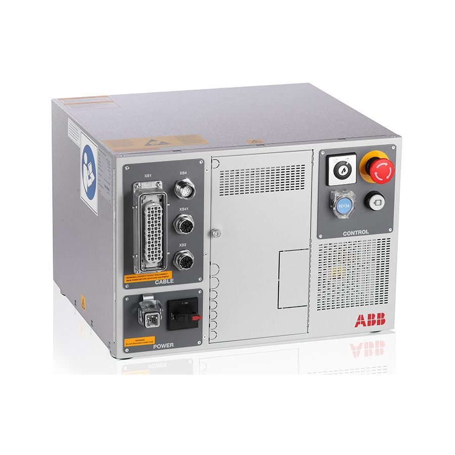
Page 45: Connections
2 Installation and commissioning 2.6.1 Connectors on the IRC5 Compact controller 2.6 Connections 2.6.1 Connectors on the IRC5 Compact controller Front panel connectors The following describes the connection interface on the front panel of the IRC5 Compact Controller. CAUTION Always inspect the connector for dirt or damage before connecting it to the controller. - Page 46 2 Installation and commissioning 2.6.1 Connectors on the IRC5 Compact controller Continued xx0900000266 XS8 Additional axis, power cable connector (not used in this release) XS4 FlexPendant connector XS7 I/O connector XS9 Safety connector XS1 Power cable connector XS0 Power input connector...
-
Page 47: Connecting A Flexpendant
Locate the FlexPendant socket connector The controller must be in manual mode. on the controller. Plug in the FlexPendant cable connector. Screw the connector lock ring firmly by turning it clockwise. 3HAC035738-001 Revision: E © Copyright 2009-2013 ABB. All rights reserved. -
Page 48: Connecting A Pc To The Service Port
The illustration below shows the two main ports on the computer unit: the Service Port and the LAN port. Make sure the LAN (factory network) is not connected to any of the service ports! xx1100000557 Service port Continues on next page 3HAC035738-001 Revision: E © Copyright 2009-2013 ABB. All rights reserved. - Page 49 LAN port (connects to factory LAN) Connections to ports may be done as detailed below. Connection to/from: Detailed in section: Connecting the IRC5 Compact to the fact- ory LAN. Connecting a PC to the IRC5 Compact Proceed as detailed below.
-
Page 50: Connection To Serial Channel
The serial channel connector is located behind the cover on the front panel of the controller. The following illustration shows its location. xx0900000270 Serial channel connector (COM1) Continues on next page 3HAC035738-001 Revision: E © Copyright 2009-2013 ABB. All rights reserved. - Page 51 Removable cover for the serial port Required equipment Equipment Note RS-232/422 converter DSQC 615 Main computer DSQC 639 parts on page 159 for spare part number. Circuit diagram 3HAC031403-003 Continues on next page 3HAC035738-001 Revision: E © Copyright 2009-2013 ABB. All rights reserved.
- Page 52 RS232 = 15m to RS422 = 120m. Action Info/Illustration Connect the adapter to the A cable is needed between the serial channel connector serial channel connector. and the adapter. xx0900000495 • A: cable • B: adapter 3HAC035738-001 Revision: E © Copyright 2009-2013 ABB. All rights reserved.
-
Page 53: Connecting Power Supply
Power supply cable (single phase) External circuit breaker External earth fault protection at control cables 3 -15m 30mA External earth fault protection at control cables >15m 300mA Circuit Diagram 3HAC031403-003 Continues on next page 3HAC035738-001 Revision: E © Copyright 2009-2013 ABB. All rights reserved. - Page 54 The following procedure describes how to connect the mains power to the controller. Action Connect the power cable from the power supply to connector XS0 on the front panel of the controller. 3HAC035738-001 Revision: E © Copyright 2009-2013 ABB. All rights reserved.
-
Page 55: Fitting The Connector
This section describes how to manufacture a cable for connecting the mains power to the controller. Specifications The following describes the cable and fuse requirements for the mains power connection to the IRC5 Compact controller. Component Description Cable type Flexible oil resistant rubber Cable area 3 x 2.5 mm... - Page 56 • X0.1 - power line • X0.2 - zero line • X0.PE - earth wire Assemble the connector by fitting the hood and the female connector, and tighten the screws. 3HAC035738-001 Revision: E © Copyright 2009-2013 ABB. All rights reserved.
-
Page 57: Connecting The Manipulator To The Irc5 Compact Controller
2 Installation and commissioning 2.6.7 Connecting the manipulator to the IRC5 Compact controller 2.6.7 Connecting the manipulator to the IRC5 Compact controller Connector location CAUTION Always inspect the connector for dirt or damage before connecting it to the controller. Clean or replace any damaged parts. - Page 58 2 Installation and commissioning 2.6.7 Connecting the manipulator to the IRC5 Compact controller Continued Connecting the manipulator cable Use this procedure to connect the power cable from the IRC5 Compact controller to the manipulator. Action DANGER Before commencing any work inside the cabinet, please observe the safety information...
-
Page 59: Descriptions For Contacts Xs7, Xs9, Xs10, Xs11, Xs12 And Xs13
Amphenol L717HDB44P D-sub hood Amphenol L17DTZK25KFM The bridge connector can be bought from ABB (3HAC035996-001). If it is bought from the manufacturer, see circuit diagram (3HAC031403-003) for connection details. XS9 Safety This connector is internally connected with safety board. It contains the following signals: •... - Page 60 COMBICON connector, Phoenix 1778014 MSTB 2,5/5-STF-5,08 The bridge connector can be bought from ABB (3HAC037705-001). If it is bought from the manufacturer, see circuit diagram (3HAC031403-003) for connection details. XS12 Additional axis (not used in this release) This connector is internally connected with drive DSQC431.
-
Page 61: The Motors On/Motors Off Circuit
Second chain interlock GS (general mode safeguarded space stop) AS (Automatic mode safeguarded space stop) ED (TPU enabling device) Manual mode Automatic mode Operating mode selector Continues on next page 3HAC035738-001 Revision: E © Copyright 2009-2013 ABB. All rights reserved. - Page 62 The supply from internal 24V and 0 V is displayed. For external supply of GS and AS check the circuit diagram. en0900000483 Technical data per chain Limit switch Load: 300 mV Max. voltage drop: 1 V Continues on next page 3HAC035738-001 Revision: E © Copyright 2009-2013 ABB. All rights reserved.
- Page 63 See illustration below. Safety P LC IRC5 Compact Safety board (A21) Safety relay Contact X9 X9.30 (AS1+) X9.31 (24 V) X9.22 (AS2-) X9.20 (0 V) en0900000482 Continues on next page 3HAC035738-001 Revision: E © Copyright 2009-2013 ABB. All rights reserved.
- Page 64 X1:2 X1:3 X2:1 X2:2 X2:7 X2:8 X2:6 X2:5 X2:4 X2:2 X2:3 xx1000001009 Internal Ext stop FlexPendant Cabinet ES1 internal Run chain 1 top Internal ES2 internal Continues on next page 3HAC035738-001 Revision: E © Copyright 2009-2013 ABB. All rights reserved.
- Page 65 Note! In case of interference, the external supply must be properly filtered. Rated current per chain 40 mA Max. potential in relation to the cabinet earthing 300 V and other signal groups. Signal class Control signals 3HAC035738-001 Revision: E © Copyright 2009-2013 ABB. All rights reserved.
-
Page 66: Emergency Stop Output
2.6.10 Emergency stop output Emergency stop output through safety relay The IRC5 Compact does not have an emergency stop output from the safety board. The emgergency stop output can be extended by adding one safety relay. The diagram below shows the connection of a safety relay, type RT6 from Jokab Safety. -
Page 67: Opening The Irc5 Compact Controller
2 Installation and commissioning 2.7.1 Accessing the controller parts 2.7 Opening the IRC5 Compact controller 2.7.1 Accessing the controller parts Removing the top cover Action Info/illustration DANGER Before commencing any work inside the cabinet, please observe the safety information in section... - Page 68 Push the right side cover towards the back of controller to release it from the bend of the front panel, and then pull upwards to remove it. Continues on next page 3HAC035738-001 Revision: E © Copyright 2009-2013 ABB. All rights reserved.
- Page 69 Remove the top cover of the cabinet. Remove the left side cover of the cabinet. Remove the two attachment screws on the back cover of the cabinet. xx0900000573 • A: attachment screws Continues on next page 3HAC035738-001 Revision: E © Copyright 2009-2013 ABB. All rights reserved.
- Page 70 Lift the middle layer with one hand and turn over the prop from under the middle layer to support on the groove on the back cover of the cabinet. xx0900000577 • prop Continues on next page 3HAC035738-001 Revision: E © Copyright 2009-2013 ABB. All rights reserved.
- Page 71 2 Installation and commissioning 2.7.1 Accessing the controller parts Continued Action Info/illustration Fit one attachment screw for the prop in the screw hole near the groove, and tighten it. 3HAC035738-001 Revision: E © Copyright 2009-2013 ABB. All rights reserved.
-
Page 72: Drive System
2 Installation and commissioning 2.8.1 Drive functions, general 2.8 Drive system 2.8.1 Drive functions, general General The robot is powered by power electronics found in the IRC5 Compact controller. Location of drive unit xx0900000501 Main Drive Unit Replacing drive system parts... -
Page 73: Memory Functions
Compact flash memory 1 GB containing ABB boot image software. Memory circuit on the computer motherboard: • 256 MB DDR SDRAM memory. Note Only use Compact flash memory and DDR SDRAM memory supplied by ABB. Further information The table gives references to additional information. Information: Found in:... -
Page 74: Connecting A Usb Memory
Handling of USB memory is described in Operating manual - IRC5 with FlexPendant, section File handling. Location on FlexPendant The location of the USB port on the FlexPendant is shown by the following illustration: xx0900000022 USB port Continues on next page 3HAC035738-001 Revision: E © Copyright 2009-2013 ABB. All rights reserved. - Page 75 2 Installation and commissioning 2.9.2 Connecting a USB memory Continued Location on the controller The location of the USB port on the IRC5 Compact controller is shown by the following illustration: xx0900000354 USB port 3HAC035738-001 Revision: E © Copyright 2009-2013 ABB. All rights reserved.
-
Page 76: I/O System
2.10.1 Definition of I/O units Inside IRC5 Compact One I/O unit is located inside the IRC5 Compact controller. It is only possible to use the I/O unit DSQC 652 inside the controller. The location of the I/O unit is as shown in the following illustration. - Page 77 Screw holes for mounting rails for I/O, gateway or encoder units How to install the I/O unit on the outside of the IRC5 Compact is described in section Installation of I/O, gateways and encoder interface units outside IRC5...
- Page 78 How to install an additional I/O unit Section Installation of I/O, gateways and encoder inter- outside the controller. face units outside IRC5 Compact on page How to replace the I/O unit inside Section Replacement of I/O unit on page 101.
-
Page 79: Installation Of Add-Ons
FlexPendant connector Required equipment Equipment Art. no. Note Wall cabinet IRC5 3HAC038671-001 External Operator's panel 3HAC038672-001 cable 3HAC038673-001 15 m 3HAC038674-001 30 m Circuit Diagram 3HAC031403-003 Continues on next page 3HAC035738-001 Revision: E © Copyright 2009-2013 ABB. All rights reserved. - Page 80 Connect the round connector from the ex- ternal operator's panel harness to XS4 on the controller. Continues on next page 3HAC035738-001 Revision: E © Copyright 2009-2013 ABB. All rights reserved.
- Page 81 Connect the connectors and earth cable inside the wall cabinet. Mount the front panel of the external oper- ator's panel on the wall cabinet with four attachment screws. 3HAC035738-001 Revision: E © Copyright 2009-2013 ABB. All rights reserved.
-
Page 82: Installation Of I/O, Gateways And Encoder Interface Units Outside Irc5 Compact
2 Installation and commissioning 2.11.2 Installation of I/O, gateways and encoder interface units outside IRC5 Compact 2.11.2 Installation of I/O, gateways and encoder interface units outside IRC5 Compact Location I/O, Gateways and encoder interface units can be mounted on mounting rails on the outside of the IRC5 Compact controller. - Page 83 2 Installation and commissioning 2.11.2 Installation of I/O, gateways and encoder interface units outside IRC5 Compact Continued Fitting Use this procedure to fit the I/O unit on the IRC5 Compact controller. Action Note/illustration DANGER Before commencing any work inside the...
-
Page 84: Installation Of Remote Service Antenna
Remote Service box Mounting bracket Installing the Remote Service box Action Info Remove the thumb screw and open the protective cover on the front of the cabinet. Continues on next page 3HAC035738-001 Revision: E © Copyright 2009-2013 ABB. All rights reserved. - Page 85 A: Remote Service WAN • B: Antenna connector • C: Remote Service LAN Close the protective cover and tighten the thumb screw. Place the antenna on top of the controller. 3HAC035738-001 Revision: E © Copyright 2009-2013 ABB. All rights reserved.
-
Page 86: Installation Of External Terminal Blocks
The external terminal blocks can be located on top of the controller or on the right side of the controller. xx1000000975 Required equipment Equipment Art. no. Harn-Terminal block unit 3HAC039346-001 Continues on next page 3HAC035738-001 Revision: E © Copyright 2009-2013 ABB. All rights reserved. - Page 87 • A: Screw holes for mounting rail Connect XP7 and XP9 to the connector XS7 and XS9 on the front of the cabinet. 3HAC035738-001 Revision: E © Copyright 2009-2013 ABB. All rights reserved.
- Page 88 This page is intentionally left blank...
-
Page 89: Maintenance
3.1 Maintenance schedule, controller IRC5 Compact 3 Maintenance 3.1 Maintenance schedule, controller IRC5 Compact General The IRC5 Compact robot controller must be maintained at regular intervals to ensure its function. The maintenance activities and their respective intervals are specified below: Intervals... -
Page 90: Inspection Activities
3 Maintenance 3.2.1 Inspection of controller 3.2 Inspection activities 3.2.1 Inspection of controller Inspecting the IRC5 Compact controller Use this procedure to inspect the IRC5 Compact controller. Action Note/illustration DANGER Before commencing any work inside the cabinet, please observe the safety information in section... -
Page 91: Changing/Replacing Activities
Certain activities to be performed as specified in the Maintenance Schedule are not detailed in this chapter, but in the Repairs chapter. Please refer to the Repair chapter of the equipment in question. 3HAC035738-001 Revision: E © Copyright 2009-2013 ABB. All rights reserved. -
Page 92: Cleaning Activities
Never: • remove any covers or other protective devices when cleaning the outside of the controller! • use compressed air or spray with a high pressure cleaner! 3HAC035738-001 Revision: E © Copyright 2009-2013 ABB. All rights reserved. -
Page 93: Cleaning The Flexpendant
Clean the touch screen This section details how to clean the touch screen. Action Info/Illustration Before cleaning the screen, tap theLock Screen on the ABB menu. en0400001221 Continues on next page 3HAC035738-001 Revision: E © Copyright 2009-2013 ABB. All rights reserved. - Page 94 To unlock the screen, follow the instructions on the screen. en0400000658 Do's and don'ts! The section below specifies some special considerations when cleaning the FlexPendant. Always: • use ESD Protection Continues on next page 3HAC035738-001 Revision: E © Copyright 2009-2013 ABB. All rights reserved.
- Page 95 FlexPendant! • spray with a high pressure cleaner! • clean the device, operating panel and operating elements with compressed air, solvents, scouring agent or scrubbing sponges. 3HAC035738-001 Revision: E © Copyright 2009-2013 ABB. All rights reserved.
- Page 96 This page is intentionally left blank...
-
Page 97: Repair
4 Repair 4.1 Overview 4 Repair 4.1 Overview Report replacements When replacing a unit in the controller, report to ABB: • the serial number • article number • revision of both the replaced unit and the replacement unit. This is particularly important for the safety equipment to maintain the safety integrity of the installation. -
Page 98: Replacement Of Safety Board
Before commencing any work inside the cabinet, please observe the safety information in section DANGER - Make sure that the main power has been switched off! on page Continues on next page 3HAC035738-001 Revision: E © Copyright 2009-2013 ABB. All rights reserved. - Page 99 • A: Attachment screws Disconnect all connectors. Make a note of all connections. Remove the eight attachment screws. xx0900000566 Gently lift the safety board out. Continues on next page 3HAC035738-001 Revision: E © Copyright 2009-2013 ABB. All rights reserved.
- Page 100 Refit the safety board unit (board with plate) without pushing it in all the way. Reconnect all connectors. Push the safety board unit all the way in and refit the attachment screws. 3HAC035738-001 Revision: E © Copyright 2009-2013 ABB. All rights reserved.
-
Page 101: Replacement Of I/O Unit
4.3 Replacement of I/O unit General An I/O unit may be installed in the IRC5 Compact controller. This is specified in Definition of I/O units on page How to configure the I/O unit is detailed in Operating manual - RobotStudio. - Page 102 WARNING - The unit is sensitive to ESD! on page 30 Hook the unit back onto the mounting rail and snap it gently in position. Reconnect all connectors disconnected during removal. 3HAC035738-001 Revision: E © Copyright 2009-2013 ABB. All rights reserved.
-
Page 103: Replacement Of Backup Energy Bank
The following illustration shows the location of the backup energy bank in IRC5 Compact. xx0900000326 Backup energy bank Required equipment Equipment Note Backup energy bank DSQC 655 Controller system parts on page 157. Circuit Diagram 3HAC031403-003 Continues on next page 3HAC035738-001 Revision: E © Copyright 2009-2013 ABB. All rights reserved. - Page 104 DANGER - Make sure that the main power has been switched off! on page Refit the new backup energy bank. Continues on next page 3HAC035738-001 Revision: E © Copyright 2009-2013 ABB. All rights reserved.
- Page 105 Note/illustration Refit the attachment screws, and tighten them. xx0900000547 • A: Backup energy bank • B: connector • C: attachment screws Reconnect the connector X7 to the power distribution board. 3HAC035738-001 Revision: E © Copyright 2009-2013 ABB. All rights reserved.
-
Page 106: Replacement Of Motherboard
The location of the motherboard is shown by the following illustration. xx0900000328 Motherboard Required equipment Equipment Note Computer unit DSQC 639 Controller system parts on page 157. Circuit diagram 3HAC031403-003 Continues on next page 3HAC035738-001 Revision: E © Copyright 2009-2013 ABB. All rights reserved. - Page 107 4 Repair 4.5 Replacement of motherboard Continued Removal Use this procedure to remove the motherboard from IRC5 Compact. Action Note/illustration DANGER Before commencing any work inside the cab- inet, please observe the safety information in section DANGER - Make sure that the main...
- Page 108 Tip: Use a long screwdriver to increase reachability. xx0900000568 Lift the middle layer of the cabinet and secure Disconnect all cables from the motherboard. Continues on next page 3HAC035738-001 Revision: E © Copyright 2009-2013 ABB. All rights reserved.
- Page 109 Note: Always grip the board around the edges to avoid damage to the board or its compon- ents! xx0900000329 Refitting Use this procedure to refit the motherboard in IRC5 Compact. Action Note/illustration DANGER Before commencing any work inside the cabinet, please observe the safety information...
- Page 110 Reconnect all cables to the motherboard. Refit the left and right side covers to the cab- inet and secure with attachment screws. Refit the top cover to the cabinet and secure with attachment screws. 3HAC035738-001 Revision: E © Copyright 2009-2013 ABB. All rights reserved.
-
Page 111: Replacement Of Ddr Sdram Memory On Motherboard
The following illustration shows the location of the DDR SDRAM memory. xx0900000331 Motherboard DDR SDRAM memory Required equipment Equipment Note DDR SDRAM 256MB Controller system parts on page 157. Circuit diagram 3HAC031403-003 Continues on next page 3HAC035738-001 Revision: E © Copyright 2009-2013 ABB. All rights reserved. - Page 112 Before commencing any work inside the cabinet, please observe the safety information in section DANGER - Make sure that the main power has been switched off! on page Continues on next page 3HAC035738-001 Revision: E © Copyright 2009-2013 ABB. All rights reserved.
- Page 113 ESD safe bag and fit it into position on the motherboard. xx0600003033 • A: DDR SDRAM memory NOTE! Always grip the memory around the edges to avoid damage to the memory or its components! 3HAC035738-001 Revision: E © Copyright 2009-2013 ABB. All rights reserved.
-
Page 114: Replacement Of Devicenet Lean Board
The following illustration shows the location of the DeviceNet Lean board. xx0900000624 DeviceNet Lean board Required equipment Equipment Info DeviceNet Lean board DSQC 572 Main computer DSQC 639 parts on page 159. Continues on next page 3HAC035738-001 Revision: E © Copyright 2009-2013 ABB. All rights reserved. - Page 115 Lift the middle layer of the cabinet and secure it. Lifting the middle layer on page Disconnect the connectors from the unit. Gently lift the DeviceNet Lean board straight up. Continues on next page 3HAC035738-001 Revision: E © Copyright 2009-2013 ABB. All rights reserved.
- Page 116 DeviceNet Lean board from the card bracket. xx0900000626 Fit the DeviceNet Lean board into position in the cabinet. Secure it with its attachment screws. 3HAC035738-001 Revision: E © Copyright 2009-2013 ABB. All rights reserved.
-
Page 117: Replacement Of Pci Boards
DSQC 687. Profibus communication is described in Application manu- al - PROFIBUS-DP. DeviceNet Master/Slave single 3HAC037084-001 DSQC 658. DeviceNet communica- tion is described in Application manual - DeviceNet. Continues on next page 3HAC035738-001 Revision: E © Copyright 2009-2013 ABB. All rights reserved. - Page 118 • A: thumb screw Identify the card to be replaced. The barcode sticker contains in- formation on type designation. Continues on next page 3HAC035738-001 Revision: E © Copyright 2009-2013 ABB. All rights reserved.
- Page 119 The unit is sensitive to ESD. Before handling the unit please read the safety information in the section WARNING - The unit is sensitive to ESD! on page 30 Continues on next page 3HAC035738-001 Revision: E © Copyright 2009-2013 ABB. All rights reserved.
- Page 120 Reconnect any additional cables to the PCI board. Close the middle layer of the cabinet. Make sure the robot system is configured to reflect Detailed in section Required the PCI cards installed. equipment on page 117. 3HAC035738-001 Revision: E © Copyright 2009-2013 ABB. All rights reserved.
-
Page 121: Replacement Of Fieldbus Adapter
- PROFINET Fieldbus Ad- apter Application manual - EtherNet/IP 3HAC028509-001 Contains information on how to Fieldbus Adapter configure the system for Ether- net/IP Fieldbus Adapter DSQC 669. Continues on next page 3HAC035738-001 Revision: E © Copyright 2009-2013 ABB. All rights reserved. - Page 122 • A: thumb screw Identify the fieldbus adapter. The barcode sticker contains information on type designation. Disconnect the cable to/from the fieldbus adapter. Continues on next page 3HAC035738-001 Revision: E © Copyright 2009-2013 ABB. All rights reserved.
- Page 123 A: Attachment screws (2 pcs) • B: Fastening mechanism Grip the loosened attachment screws and gently pull the fieldbus adapter out in the direction of the arrow. xx0700000195 Continues on next page 3HAC035738-001 Revision: E © Copyright 2009-2013 ABB. All rights reserved.
- Page 124 WARNING Push carefully so no pins are damaged. Make sure that the adapter is pushed straight onto the rails. xx0700000194 Continues on next page 3HAC035738-001 Revision: E © Copyright 2009-2013 ABB. All rights reserved.
- Page 125 • A: Attachment screws • B: Fastening mechanism Reconnect the cable to the fieldbus ad- apter. Make sure the robot system is configured to reflect the fieldbus adapter installed. 3HAC035738-001 Revision: E © Copyright 2009-2013 ABB. All rights reserved.
-
Page 126: Replacement Of Compact Flash Memory
Location The location of the Compact Flash memory slot is shown by the following illustration. xx0900000344 Slot for Compact Flash memory Note Only use Compact flash memory supplied by ABB. Required equipment Equipment Note Compact Flash 1GB DSQC 656 1GB NOTE! Only use Compact flash memory supplied by ABB. - Page 127 • A: thumb screw Gently, pull the Compact Flash memory out in the direction of the arrow. xx0900000609 Continues on next page 3HAC035738-001 Revision: E © Copyright 2009-2013 ABB. All rights reserved.
- Page 128 The unit is sensitive to ESD. Before handling the unit please read the safety information in the section WARNING - The unit is sensitive to ESD! on page 30 Refit the Compact Flash memory. xx0900000608 3HAC035738-001 Revision: E © Copyright 2009-2013 ABB. All rights reserved.
-
Page 129: Replacement Of Drive Unit
The following illustration shows the location of the Main Drive Unit. xx0900000449 Main Drive Unit Attachment screws for Main Drive Unit Required equipment Equipment Note Main Drive Unit Controller system parts on page 157. Continues on next page 3HAC035738-001 Revision: E © Copyright 2009-2013 ABB. All rights reserved. - Page 130 DANGER - Make sure that the main power has been switched off! on page Fit the unit in its intended position and orientation. Secure it with its attachment screws. Reconnect any connectors disconnected at removal. 3HAC035738-001 Revision: E © Copyright 2009-2013 ABB. All rights reserved.
-
Page 131: Replacement Of Axis Computer Dsqc 668
The location of the axis computer is shown by the following illustration. xx0900000348 Axis computer unit Required equipment Equipment Info Axis computer DSQC 668 Controller system parts on page 157. Continues on next page 3HAC035738-001 Revision: E © Copyright 2009-2013 ABB. All rights reserved. - Page 132 Make a note of any connections. Remove the attachment screws. xx0900000548 • A: axis computer • B: attachment screws Gently lift the axis computer unit straight up. Continues on next page 3HAC035738-001 Revision: E © Copyright 2009-2013 ABB. All rights reserved.
- Page 133 Gently fit the axis computer board into the cover Refit the seven attachment screws. Gently lower the axis computer unit in position. Refit the attachment screws. Reconnect all the connectors. 3HAC035738-001 Revision: E © Copyright 2009-2013 ABB. All rights reserved.
-
Page 134: Replacement Of System Fans
DANGER - Make sure that the main power has been switched off! on page CAUTION Hot surface on top of the bleeder. Risk of burns. Be careful when removing the unit. Continues on next page 3HAC035738-001 Revision: E © Copyright 2009-2013 ABB. All rights reserved. - Page 135 Fasten the attachment screw on the fan receptacle. Connect the connectors to the fan. Put the fan cover in place and push it leftwards. Fasten the three attachment screws on the fan cover. 3HAC035738-001 Revision: E © Copyright 2009-2013 ABB. All rights reserved.
-
Page 136: Replacement Of Brake Resistor Bleeder
Before commencing any work inside the cabinet, please ob- serve the safety information in section DANGER - Make sure that the main power has been switched off! on page Continues on next page 3HAC035738-001 Revision: E © Copyright 2009-2013 ABB. All rights reserved. - Page 137 Before commencing any work inside the cabinet, please ob- serve the safety information in section DANGER - Make sure that the main power has been switched off! on page Continues on next page 3HAC035738-001 Revision: E © Copyright 2009-2013 ABB. All rights reserved.
- Page 138 Refit the fan cover, push it left- wards to the grooves. Refit the attachment screws for the fan cover, and tighten them. Reconnect the bleeder cable to the drive unit. 3HAC035738-001 Revision: E © Copyright 2009-2013 ABB. All rights reserved.
-
Page 139: Replacement Of Remote Service Box
Before commencing any work inside the cabinet, please observe the safety information in section DANGER - Make sure that the main power has been switched off! on page Continues on next page 3HAC035738-001 Revision: E © Copyright 2009-2013 ABB. All rights reserved. - Page 140 The unit is sensitive to ESD. Before handling the unit please read the safety information in the section WARNING - The unit is sensitive to ESD! on page 30 Fit the Remote Service box in position. Reconnect all connectors to the Remote Service box. 3HAC035738-001 Revision: E © Copyright 2009-2013 ABB. All rights reserved.
-
Page 141: Replacement Of Power Supply
Do not route or place cables on top of the power distribution board. Required equipment Equipment Note Power distribution board DSQC 662 Controller system parts on page 157. Circuit diagram 3HAC031403-003 Continues on next page 3HAC035738-001 Revision: E © Copyright 2009-2013 ABB. All rights reserved. - Page 142 Disconnect all connectors from the power distribution board. Remove the attachment screws. xx0900000549 • A: power distribution board • B: attachment screws Lift the power distribution board straight Continues on next page 3HAC035738-001 Revision: E © Copyright 2009-2013 ABB. All rights reserved.
- Page 143 Reconnect the connectors X1 - X9. CAUTION Hot surface on top of the power distribu- tion board unit. Do not route or place cables on top of the power distribution board. 3HAC035738-001 Revision: E © Copyright 2009-2013 ABB. All rights reserved.
-
Page 144: Replacement Of System Power Supply
Remove the top cover and left side cover of the Removing the top cover on cabinet. page 67 Removing the left side cover on page Continues on next page 3HAC035738-001 Revision: E © Copyright 2009-2013 ABB. All rights reserved. - Page 145 Before commencing any work inside the cabinet, please observe the safety information in section DANGER - Make sure that the main power has been switched off! on page Continues on next page 3HAC035738-001 Revision: E © Copyright 2009-2013 ABB. All rights reserved.
- Page 146 • A: upper attachment screws • B: lower attachment screws Refit the two lower attachment screws. Tighten the attachment screws (4 pcs). Reconnect all connectors to the unit. 3HAC035738-001 Revision: E © Copyright 2009-2013 ABB. All rights reserved.
-
Page 147: Replacement Of Line Filter
DANGER - Make sure that the main power has been switched off! on page Remove the top cover of the cabinet. Removing the top cover on page Continues on next page 3HAC035738-001 Revision: E © Copyright 2009-2013 ABB. All rights reserved. - Page 148 DANGER - Make sure that the main power has been switched off! on page Fit the line filter in position and secure the four attachment screws. Reconnect all connectors disconnected during removal. 3HAC035738-001 Revision: E © Copyright 2009-2013 ABB. All rights reserved.
-
Page 149: Decommissioning
These parts must also be disposed of in accordance with the current legislation of the country in which the robot and control unit are installed. 3HAC035738-001 Revision: E © Copyright 2009-2013 ABB. All rights reserved. -
Page 150: Environmental Information
Batteries, NiCad or Lithium Main computer Copper Cables Steel Cabinet structure, plates, screws, etc. Plastic/rubber Cables, connectors, etc. Aluminium Heat sinks on power supplies and drive units Lead Electronics Brominated flame retardants Electronics 3HAC035738-001 Revision: E © Copyright 2009-2013 ABB. All rights reserved. -
Page 151: Reference Information
6 Reference information 6.1 Introduction 6 Reference information 6.1 Introduction General This chapter includes general information, complementing the more specific information in the different procedures in the manual. 3HAC035738-001 Revision: E © Copyright 2009-2013 ABB. All rights reserved. -
Page 152: Applicable Safety Standards
Safety of machinery - General requirements for the design and construction of fixed and movable guards Other standards Standard Description ANSI/RIA R15.06 Safety requirements for industrial robots and robot systems Continues on next page 3HAC035738-001 Revision: E © Copyright 2009-2013 ABB. All rights reserved. - Page 153 6.2 Applicable safety standards Continued Standard Description ANSI/UL 1740 Safety standard for robots and robotic equipment (option 429-1) CAN/CSA Z 434-03 Industrial robots and robot Systems - General safety require- ments (option 429-1) 3HAC035738-001 Revision: E © Copyright 2009-2013 ABB. All rights reserved.
-
Page 154: Unit Conversion
3.28 ft. 39.37 in Weight 1 kg 2.21 lb. Weight 0.035 ounces Pressure 1 bar 100 kPa 14.5 psi Force 0.225 lbf Moment 1 Nm 0.738 lbf-ft Volume 0.264 US gal 3HAC035738-001 Revision: E © Copyright 2009-2013 ABB. All rights reserved. -
Page 155: Screw Joints
Maximum allowed total deviation from the specified value is 10%! The table below specifies the recommended standard tightening torque for oil-lubricated screws with slotted or cross-recess heads. Dimension Tightening torque (Nm) Class 4.8, oil-lubricated M2.5 0.25 3HAC035738-001 Revision: E © Copyright 2009-2013 ABB. All rights reserved. - Page 156 This page is intentionally left blank...
-
Page 157: Spare Parts
3HAC028179-001 Axis computer DSQC 668 3HAC026253-001 System Power Supply DSQC 661 3HAC026254-001 Power distribution board DSQC 662 3HAC025562-001 Backup energy bank DSQC 655 3HAC037698-001 Line filter Continues on next page 3HAC035738-001 Revision: E © Copyright 2009-2013 ABB. All rights reserved. - Page 158 Description Note 3HAC025784-001 ADCombi I/O DSQC 651 3HAC025917-001 Digital 24V I/O DSQC 652 3HAC025918-001 Digital I/O with relay outputs DSQC 653 * Mounted outside controller cabinet Continues on next page 3HAC035738-001 Revision: E © Copyright 2009-2013 ABB. All rights reserved.
- Page 159 (its casing is not used with IRC5 Compact). 3HAC025465-011 Compact flash 1GB DSQC656 1GB 3HAC14944-1 RS-232/422 converter DSQC 615 3HAC025779-001 DeviceNet M/S single DSQC 658 Continues on next page 3HAC035738-001 Revision: E © Copyright 2009-2013 ABB. All rights reserved.
- Page 160 Brake resistor bleeder asm 3HAC037699-001 Handle for 6 mm switch 3HAC15312-1 Cam Switch 3HAC029105-001 Fan with receptacle 3HAB2997-1 Wrist band 3HAC037700-001 Contactor ASL16-30-10 DC24V 3HAC031561-001 Auxiliary contact CA3-10 3HAC031562-001 Auxiliary contact CA3-01 3HAC035738-001 Revision: E © Copyright 2009-2013 ABB. All rights reserved.
-
Page 161: Manipulator Cables
3HAC9038-4 Control cable power L=30m Cable packages for IRB 360 (including signal, power and customer cables) Art. no. Description 3HAC029903-001 Control cable, power and signal L=3m Continues on next page 3HAC035738-001 Revision: E © Copyright 2009-2013 ABB. All rights reserved. - Page 162 3HAC2539-1 Control cable power L=22m 3HAC2564-1 Control cable power L=30m 3HAC9038-1 Control cable power L=7m 3HAC9038-2 Control cable power L=15m 3HAC9038-3 Control cable power L=22m 3HAC9038-4 Control cable power L=30m 3HAC035738-001 Revision: E © Copyright 2009-2013 ABB. All rights reserved.
-
Page 163: Circuit Diagrams
Circuit diagram - IRB 6600 type B 3HAC13347-1 3HAC025744-001 Circuit diagram - IRB 6620 3HAC025090-001 Circuit diagram - IRB 6620 / IRB 6620LX 3HAC025090-001 Circuit diagram - IRB 6640 3HAC025744-001 Continues on next page 3HAC035738-001 Revision: E © Copyright 2009-2013 ABB. All rights reserved. - Page 164 8.1 About circuit diagrams Continued Product Article numbers for circuit diagrams Circuit diagram - IRB 6650S 3HAC13347-1 3HAC025744-001 Circuit diagram - IRB 6660 3HAC025744-001 3HAC029940-001 Circuit diagram - IRB 7600 3HAC13347-1 3HAC025744-001 3HAC035738-001 Revision: E © Copyright 2009-2013 ABB. All rights reserved.
-
Page 165: Index
86 power cables, 161 power distribution board, replace, 141 power supply, 141, 144 fans, 134 power supply, connect, 53 fieldbus adapter, replace, 121 power supply contact XS10, 59 filter, 147 3HAC035738-001 Revision: E © Copyright 2009-2013 ABB. All rights reserved. - Page 166 XS9, 59 XS7 I/O, 59 safety risk XS9 Safety, 59 electric parts, 14 XS10 Power Supply, 59 voltage, 14 XS11 DeviceNet, 60 safety signals XS13 Axis selector, 60 3HAC035738-001 Revision: E © Copyright 2009-2013 ABB. All rights reserved.
- Page 168 Telephone +46 (0) 21 344 400 ABB AS, Robotics Discrete Automation and Motion Box 265 N-4349 BRYNE, Norway Telephone: +47 51489000 ABB Engineering (Shanghai) Ltd. 5 Lane 369, ChuangYe Road KangQiao Town, PuDong District SHANGHAI 201319, China Telephone: +86 21 6105 6666 ABB Inc.
Need help?
Do you have a question about the IRC5 Compact and is the answer not in the manual?
Questions and answers