Table of Contents
Advertisement
Quick Links
Advertisement
Table of Contents

Summary of Contents for Honeywell INTEVIO
- Page 1 INTEVIO PA/VA System User Manual M_ 2000061157_EN54_1.5 M_XXXXXX_CN_1.0...
- Page 2 The contents of this document are subject to revision without notice due to continued progress in methodology, design, and manufacturing. Honeywell shall have no liability for any error or damage of any kind resulting from the use of this document.
-
Page 3: Safety Precautions
Safety Guidelines Danger This sign reminds users of “dangerous voltage” on the product. Caution This sign reminds users of important instructions attached to the product. To prevent electric shock, this equipment plug shall not be used as a conductor to extend any power supply line. Safety guideline Do not block the equipment’s ventilation opening or put other equipment on it. -
Page 4: Label And User's Manual
Requirements on grid power supply voltage by the equipment: AC 220V (-15% ~ +10%) 50 ~ 60 Hz. In case of too high or too low voltage, or that which greatly fluctuates, it is recommended that an AC regulated power supply should be installed. ... -
Page 5: Network Security
Any person except an authorized & trained maintenance engineer is forbidden to disassemble or change parts of the device. It is forbidden to communicate between this INTEVIO system and third-party systems unless updating the software of this device. ... -
Page 6: Table Of Contents
Table of Contents Safety Guidelines ..........................i Safety Precautions ............................i Electricity Utilization Safety ......................... i Transportation Safety .......................... i Environmental Requirements ......................i Safe Use Precautions ........................ii Label and User’s Manual........................ii Network Security ............................iii Placement ............................iii Password Precaution ........................ - Page 7 Preparing Auxiliary Materials ......................32 Preparing Cables and Auxiliary Equipment ..................32 Packing List Inspection ........................33 System Installation ........................... 33 Installing the Devices in the Appliance Cabinet ................. 33 Installing the Remote Call Station on Desktop ................... 34 Installing the Remote Call Station in Cabinet..................36 Flush Installation of a Remote Call Station ..................
- Page 8 RK-AMP500 500W Class-D Power Amplifier ..................96 RK-MIC Remote Call Station ......................96 Operations ............................... 98 Power On & Off ..........................98 Reset .............................. 98 ACK ..............................98 Test ..............................98 Monitor ............................99 Volume Setting ..........................99 Zone/Group Selection ........................99 Cancel Zone Selection ........................
-
Page 9: Preface
This section introduces some troubleshooting methods and the maintenance related information of INTEVIO system. Intended Reader This manual is mainly for the people who need to install, operate and maintain the INTEVIO system. Relevant Documents The following documents can be used as a reference when reading this manual: ... -
Page 10: Abbreviations
Abbreviations Acronyms are used to refer to some components, the abbreviations are as follows: Abbreviation Definition Description Amplifies the audio signal and Power Amplifier outputs the high-power audio signal to drive loudspeakers. The management of the system, which can drive 8 zones; the system Master Control Unit capacity can be increased to extend three number of zones or speaker... -
Page 11: System Overview
1 System Overview This INTEVIO PA/VA System provides a number of public address solutions. It is highly integrated with device simplification, easy expansion, simple installation, convenient operation, etc. The system is designed in accordance with EN 50849:2017 and EN 54-16:2008. -
Page 12: System Components
500W Class-D Power Amplifier RK-MIC Remote Call Station HMC-K4 Expansion Keypad (4 Keys) HMC-K8 Expansion Keypad (8 Keys) INTEVIO Configuration Tool System Configuration Software HN-PTT PTT Microphone HN-EOL End-of-line Module HN-AIO2X2 Audio Control Module ... -
Page 13: System Structure
System Structure The INTEVIO PA/VA system requires only one RK-MCU to be installed, which is connected to zone expanders and call stations and uses its control and audio bus to manage all the devices in the system. Up to 15 RK-ZONE8 can be connected enabling up to 128 zones. Remote call stations (RK-... -
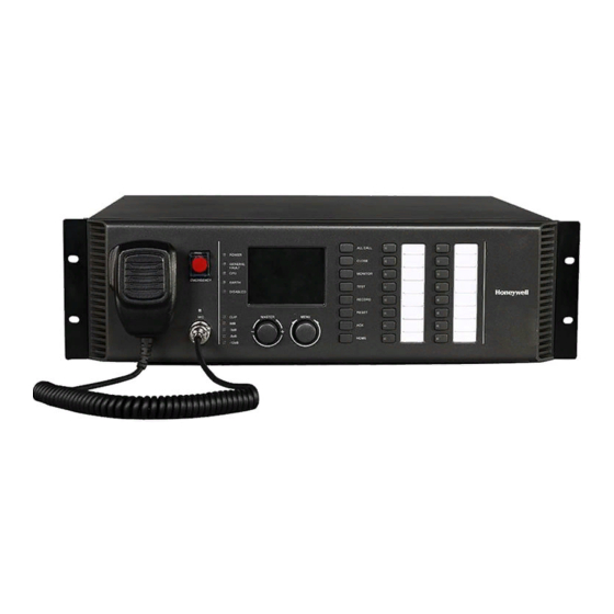
Page 14: Rk-Mcu Master Control Unit
RK-MCU Master Control Unit The Master Control Unit is the central management device of the system, which is used to manage and monitor all devices in the system and perform various operations. The Master Control Unit has audio storage, broadcast, zone control, monitor, timing control, fault diagnosis, etc. functions. The built-in 500W Class-D power amplifier drives a maximum of 8 zones (16 loudspeaker lines) to meet the requirements of small applications. - Page 15 No. Buttons/Indicators Description Microphone bracket The microphone bracket is used for the PTT microphone. A protective cover is fitted over the emergency button to prevent accidental operation. Emergency button If switching to manual emergency mode, raise the protective cover, then press the button. The indicator light turns red. Used to connect microphone to MCU.
- Page 16 Rear Panel Parts/Ports Description To enable a signal output to channel 1.This can be connected Audio output of CH1 to an external power amplifier or third-party devices. To enable the signal output to channel 2. This can be Audio output of CH2 connected to an external power amplifier or third-party devices.
-
Page 17: Technical Specification
Parts/Ports Description Interfaces will be connected to third party systems: ALARM - A dry contact output to transmit the voice alarm status to third party system. FAULT – A dry contact output to transmit the general fault status to third party system. System interface ... - Page 18 Parameters Values 80 dB, A-weighed MIC/LINE Input Input sensitivity 5 mV/1 V, set by DIP switch 20 KΩ Input impedance Frequency response 80 Hz-18 kHz, ± 3dB 80 dB, A-weighted Phantom power output 24 V DC, set by DIP switch Audio Output Output channels CH1, CH2 and record...
-
Page 19: Rk-Zone8 Zone Expander
Parameters Values Storage temperature -40C~+70C (-40F to +158F) Specification Dimension (W*H*D) 482 mm × 133.5 mm × 420 mm Packing dimension 580 mm × 279 mm × 552 mm (W*H*D) Net weight 14.3 Kg Gross weight 17.4 Kg RK-ZONE8 Zone Expander RK-ZONE8 is the zone extension device to expand the quantity of loudspeaker lines and interfaces. - Page 20 Button/Indicator Description Light To indicate the status of power supply, main power fault, backup Device status power fault, earth fault, CPU fault, network fault, open circuit and indicators short circuit of contact inputs. Indicators of power amplifier To indicate fault of the connected power amplifiers. status Indicators of To indicate the work status and fault status of 8 zones.
-
Page 21: Technical Specifications
Parts/Ports Description Spare amplifier The 70V/100V audio interface of spare amplifiers. interface DC output DC24V power output. To connect to the AC power supply. A fuse must be installed in Main power & fuse the socket for over current protection. Power switch To turn on or turn off the AC power. -
Page 22: Rk-Amp500 500W Class-D Power Amplifier
Parameters Values Others DC Power output 24 V / 1 A Working Conditions 95%, without condensing Relative humidity Working temperature -10C~+55C (14F to +131F) Storage temperature -40C~+70C (-40F to +158F) Specification Dimension (W*H*D) 482 mm × 88 mm × 407 mm Packing dimension 580 mm ×... - Page 23 Button/Indicator Description Light To indicate the status of power supply, main power fault, backup power fault and protection. POWER indicates the power supply status; the light is green when the DA is powered on. MAINS indicate the main power supply fault status. If main power supply fails, the light turns yellow.
-
Page 24: Technical Specifications
Technical Specifications Parameters Values Main power supply AC 100V-240V 50/60Hz Backup power supply 21.5V DC ~ 28.5V DC Power consumption <700W Fuse T10AH 250V DA output 70V / 100V Max. output power 500W Frequency response 80Hz~18kHz (+1dB ~ - 3dB) 20KΩ... -
Page 25: Product Appearance
Supervision on microphone and communication automatically. The maximum distance between RK-MCU and RK-MIC is 600 meters via the twisted-pair cable. Call station can be powered by RK-MCU. Maximum 6 remote call stations can be connected to the system. Product Appearance Front Panel Buttons/Indicators... -
Page 26: Technical Specifications
Rear Panel Parts/Ports Description MIC volume To adjust the volume of the microphone. Line volume To adjust the volume of the line input. Loudspeaker volume To adjust the volume of the loudspeaker. This port can be connected to an external audio device, such as Line input a CD/DVD player, tuner, etc. - Page 27 Parameters Values 95%, without condensing Relative humidity Operating temperature -10C~+55C (14F to +131F) Storage temperature -40C~+70C (-40F to +158F) Specification Dimension (W*H*D) 200 × 46.5 × 200 mm Packing dimension (W*H*D) 403 × 133 × 268mm Net weight 1.4Kg Gross weight 2.5Kg...
-
Page 28: System Installation
2 System Installation Installers are required to understand the functional components of the system. Refer to the documentation provided for information on all system devices before installation. Interface Introduction RK-MCU Master Control Unit Audio Input There are 3 audio inputs on the rear panel of the RK-MCU, which can be connected to external audio devices. - Page 29 Wiring of the power amplifier interface: Signal Legend Self-testing control signal Power-saving control signal VCC (24 V DC), from device output to power amplifier Differential audio signal positive Differential audio signal negative Ground Power amplifier fault signal When power amplifier works normally, the output voltage is 24 V DC.
- Page 30 CH2B can be connected with the 100 V audio signal from an external power amplifier, which corresponds to audio channel 2 and loudspeaker lines 5 to 8. SPARE IN can be connected with a backup power amplifier, SPARE OUT interface from MCU or other zone expanders.
- Page 31 Dry Contact Output There are 8 dry contact outputs, which are from A1 to A8, each port has NO, NC and COM. This provides a connection for external modules or third-party devices, such as a volume controller. The maximum voltage and current for each dry contact output are 250 V and 5 A. System Interface System interface is used to connect to an external device or a third-party system.
- Page 32 Type Legend CH2 audio positive CH2 audio negative Ground CAN bus positive CAN bus negative Call Station Interface There are 2 call station interfaces (RJ-45) at the rear panel of the MCU, which are used to connect with remote call station(s). They include 24 V DC power, audio signal and CAN bus. Maximum 6 call stations and 2 branches can be connected.
- Page 33 USB Interface The USB interface can be used to insert a USB storage device. The port can be used only for audio playback. The LAN interface is used to connect to a PC or Ethernet switch for system configuration. User can set the function and parameters via Ethernet via the configuration software.
-
Page 34: Rk-Zone8 Zone Expander
DC Power Output The MCU has a 24 V DC power output which can be used for external power. The output current should be less than 1 A. A resettable fuse is built into the interface to avoid any damage caused from a short circuit. - Page 35 Power Amplifier Interface The power amplifier interfaces are used to connect to the external Master Control Unit with power amplifiers. It transfers the audio signal and control signal, such as self-testing, power-saving from controller to power amplifier, and transfers the fault signal, such as power fault or protection from power amplifier to controller.
- Page 36 Loudspeaker Interface RK-ZONE8 has 2 groups (A and B) of loudspeaker line terminals, each group can separately connect to 8 loudspeaker lines. 1A and 1B output the same signal and can’t be controlled separately. Matching terminals are attached in the package, the cable with a cross-section of 0.5mm to 1.5mm is recommended.
- Page 37 There are 8 dry contact outputs from B1 to B8, each port has NO, NC and COM. The external modules or a third-party device, such as volume controller can be connected. The maximum voltage and current for each dry contact output are 250V and 5A. System Extension The system extension interface is used to transmit the audio and control signals between system components, such as the RK-MCU and zone expanders.
-
Page 38: Rk-Amp500 500W Class-D Power Amplifier
The backup power interface is used to connect to a 24 V DC power source. The connector is provided in the package, a 2-pin cable with a cross-section of 1mm to 1.5mm recommended. RK-AMP500 500W Class-D Power Amplifier Audio Input LINE IN is a balanced audio interface, which used to connect to an external audio source. -
Page 39: Rk-Mic Remote Call Station
Power Input Main power interface with a resettable fuse is used to connect to an AC power source. T10 AH/250V fuse is recommended. The backup power interface is used to connect to a 24 V DC power source. The connector is provided in the package, a 2-pin cable with a cross-section of 3mm to 3.5mm recommended. -
Page 40: Preparation For Installation
Preparation for Installation Before installing the system, appropriate preparation is required to ensure a smooth installation process. Preparing tools Preparing auxiliary materials Preparing cables and auxiliary devices Packing list inspection Preparing Tools Prepare the following tools before installing the system equipment: ... -
Page 41: Packing List Inspection
CAT-5 Ethernet cable Twisted-pair cables are required to be no longer than 100m and with a diameter of 0.51mm (wire gauge of 24AWG). Shielded twisted-pair cables are recommended. Contact input/output cables and external devices (optional) The contact inputs or outputs are used to connect the system with third party device or external devices. -
Page 42: Installing The Remote Call Station On Desktop
Note: It is recommended to use an L or U-shaped plate to support the devices in the cabinet and ensure acceptable stress levels on the device brackets. Do not pile the devices with only fixing the brackets of front panel. In order to comply with the regulations of EN 54-16 certification, please install the machine legs which are provided in the packages. - Page 43 2. Connect the remote call station and key module together using the cables provided. 3. Install the bracket between them, as shown below, and fasten using the screws provided. Turn the module over. 4. Repeat these steps to install the remaining modules. Installing the Goose-neck Microphone Insert the microphone plug to the top-right socket on the RK-MIC and clockwise rotate to fasten the bottom screw.
-
Page 44: Installing The Remote Call Station In Cabinet
Installing the Remote Call Station in Cabinet Follow above procedures to connect the remote call station and key modules, then install the call station to the fixed bracket as following steps: 1.Place the remote call station in the frame. 2.With the call station in place, turn the bracket over. Use the screws provided to fasten the call station to the bracket. -
Page 45: Installing Device Labels
Installing Device Labels Installing RK-MCU Labels There are 8 zone buttons and 8 audio source buttons on the front panel of the RK-MCU. The buttons can be identified by the labels on the right. Standard labels are provided, users can write the button name on the labels, then install the labels as shown below. -
Page 46: Connecting The System
Connecting the System After installing all devices, please connect the devices as per the following instructions. Connecting Power Supply All the devices except the RK-MIC have special mains power supply interfaces and backup power supply interfaces. The Main power cable is attached in the package. For the backup power cable, users need to make it according the actual length. -
Page 47: Connecting Rk-Mcu
Connecting RK-MCU Connecting Main Power Amplifier The amplifier interface of the Master Control Unit (pictured below) is used to connect the 100V output of the power amplifier. The Master Control Unit has a 500W internal power amplifier. The high voltage signal can be outputted through the CH1A OUT port. - Page 48 4. Under the dual channel mode, if there are less than 4 zones, one external power amplifier for CH2 need to be connected as the following steps: Use twisted-pair cable to connect PA interface “CH2” of RK-MCU to the PA interface “IN” of power amplifier.
- Page 49 6. Under the dual channel mode, if there are more than 4 zones and the total power rate is more than 500W, 3 external power amplifiers need to be connected as the following steps: Use twisted-pair cable to connect PA interface “CH1” of RK-MCU to the PA interface “IN” of the first power amplifier.
- Page 50 Connecting Speaker Line Refer to the related manual of loudspeakers before connection. Follow the steps below to connect the speaker line to the RK-MCU. 1. Strip approximately 10mm of insulation from the cable and insert it into the loudspeaker terminal. Fasten the screw.
- Page 51 Note: Spur lines with volume controllers are not monitored. Connecting Contact Input There are two ways to connect external devices or the third-party device to RK-MCU using the contact inputs: 1. If the line of the contact inputs doesn’t need to be supervised, connect the relay or the switch output of the external devices or the third-party device to the contact inputs of the RK-MCU.
- Page 52 2. If the line of the contact inputs needs to be supervised, it is necessary to install 10k resistors to each switch output of the external devices or the third-party device as shown below: Connecting Dry Contact Output Each dry contact output has NO, NC and COM pins, which can be used to control third-party devices or transmit the device status.
- Page 53 3. Connecting 4-wire volume controller When connecting a 4-wire volume controller, please refer to the user’s manual of the volume controller. The diagram below shows the connection: Connecting Audio Devices There are 2 auxiliary inputs and 1 MIC/LINE input which can be connected to external audio source devices.
-
Page 54: Connecting Rk-Zone8
Connecting RK-ZONE8 Connecting Main Power Amplifiers The relevant amplifier interface of the RK-ZONE8 has a detailed description in the “Interface Introduction” section. A maximum of 4 power amplifiers can be connected to the RK-ZONE8. Select the proper connection method according to the expected application. 1.... - Page 55 4. In dual channel mode, if there are fewer than 4 zones and the total power rate is less than 500W, connect the external power amplifiers as follows: Use a twisted-pair cable to connect the PA interface “CH1” of RK-ZONE8 to the PA interface “IN”...
- Page 56 Connect the “+” and “-” of “CH2A IN” to the corresponding ports of “CH2B IN”. 6. In dual channel mode, if there are more than 4 zones and the total power rate is more than 500W, 4 external power amplifiers need to be connected as follows: Use a twisted-pair cable to connect the PA interface “CH1”...
-
Page 57: Connecting The Rk-Mic
Connecting Loudspeaker Line Please refer to the related manual for the loudspeakers before connection. Follow the steps below to connect the speaker line to the RK-ZONE8: 1. Strip about 10mm (0.4 in.) of the insulated surface of the cable and insert it into the loudspeaker terminal, then fasten the screw. -
Page 58: Connecting Spare Power Amplifier
Connecting External Audio Source RK-MIC has 1 audio input interface to connect to an external audio source, which is used for BGM broadcast. Since the interface has a TRS port with a cross-section of 3.5mm, it is necessary to use an attached cable to connect to an audio device. -
Page 59: Grounding
The connection is shown below: To ensure correct function, the configuration must follow the actual connection of the spare power amplifier. Grounding Normally, there are grounding terminals at the bottom of the cabinet or on the door of the cabinet. 1.Connecting Cabinet Grounding Wire Generally, the cabinet has a special grounding terminal. -
Page 60: Basic Settings
Basic Settings After installation, some basic settings for work mode are required. Address Setting Before system debugging, set the address of the zone expander and remote call station. Start with address 1 and increase by one number for each additional zone expander or remote call station. The setting range for the RK-ZONE8 is from 1 to 15 and the RK-MIC is from 1 to 6. - Page 61 2. Audio Channel Setting The system can support a maximum of 2 audio channels. The RK-MCU and RK-ZONE8 can support both single and dual audio channels. Before use, set the audio channel via the “MODE” switch. Switch No. Function Description ...
-
Page 62: System Hardware Checking
OFF——Disabled 3. Power-saving Mode To ensure a long backup period in case of a back-up power failure, the INTEVIO system can work in power-saving mode. In this mode, all the non-emergency functions are disabled, all power amplifiers are switched off but ready for operation again and are woken up regularly for power amplifier monitoring. - Page 63 Note: After the installation of a new system, the nameplate which is provided in the packaging of the MCU must be filled in and pasted onto the cabinet.
-
Page 64: System Configurations
Installation and Uninstallation Installation Please follow the instructions below to install the software: Double-click the installation program “INTEVIO Configuration Tool Setup.exe” and the window below is displayed: Click Next, the License Agreement page is displayed. Please carefully read the agreement. -
Page 65: Uninstallation
After the uninstallation is completed, the prompt dialog “Some content cannot be deleted, you can manually remove them” opens. Click OK to finish the uninstallation. Note: If users want to delete the remaining files manually, find the INTEVIO Configuration Tool folder in the installation directory and delete it. -
Page 66: Configuration Operation
Double click the icon on the desktop or click Start in the lower left corner of the computer desktop and select ALL Programs INTEVIO Configuration Tool to run the software, which is displayed as below: Exit or click the “X” icon... -
Page 67: Configuration Guide
Update RK-MIC chime tone Set pre-chime and end-chime for RK-MIC. Select Language Select the displayed language. Help Display the software version and copyright information. Configuration Guide Please follow steps below to configure the INTEVIO system: New/Open Task Operation Upload Project Device Configuration... -
Page 68: Project
Project The following are the steps to create a new file: 1.Select the menu Project New. The new project window is displayed as below. Set the project name, file path and MCU name. The directory can be changed and the default path is “My Documents”. - Page 69 Open The following are the steps to open a project: 1. Select the menu Project Open. The window is displayed as below: 2. Select the project file according to the location path. 3. Click the “Open” button to open the project file. The “Cancel” button will close the window. Save As ...
- Page 70 2. Enter the project name, company, contact and telephone. 3. Click the OK button to save. System Setting After creating a new file or opening a project, a tree structure with all the devices of the project will be displayed in the left side of the window. Select the root and right click to add an MCU to the project. Select the MCU and right click to display the following menu: ...
-
Page 71: Device
Delete If users want to delete a device from the project, first select the device and then right click to select Delete. Device RK-MCU Select RK-MCU and click the Device button to view the related options, such as Properties, Time, Amplifier, Supervision, Groups and Linkage. - Page 72 Both checkboxes must be activated to have proper amplifier supervision during energy-saving cycles (sleep & wake). If the Power-saving Mode checkbox is enabled, when the main power supply (AC power) of any control unit in the system is faulty, the system will disable all non-emergency functions. This option is only available when supervision of the main power supply is enabled.
- Page 73 2. Time Time is used to set the parameters related to time, which is displayed as below: Time Synchronization Time Synchronization is used to set the parameters of time synchronization for the MCU through NTP protocol, which is normally disabled by default. If NTP Server is enabled, the MCU will work as an NTP server and other devices will synchronize the time with it.
- Page 74 4. Supervision Supervision is used to enable or disable the supervision functions, the window is displayed as below: Supervision Options Users can use the software to enable or disable Main Power Supply, Backup Power Supply, PTT Microphone, Communication Fault, Fire Alarm Interface and Audio File Storage. Click the checkbox: means enabled.
- Page 75 Dry Contact Input If the dry contact inputs are connected to third-party devices, the transmission line can be supervised. This function can be configurable. If supervision is enabled, two 10k resistors should be connected to each dry contact output of the third-party device. Please refer to Connecting Contact Input for related information.
- Page 76 Group Contents Select a group and the Group Contents will display all the speaker lines of this group. Choose a device and select speaker lines to add to the group. Users can also put speaker lines into the group contents by dragging them. If users drag a device from the device list to group contents, then all the zones of the device will be added to the group.
- Page 77 displayed as below: Users can select the reset mode for the fire alarm: Auto-Reset If Auto-Reset is selected, when the system receives a fire alarm signal from contact inputs, it will start to broadcast the voice alarm automatically. When the fire alarm signals are cleared, the voice alarm broadcast will be reset automatically.
- Page 78 To meet French regulations, the reset mode should be set to “Manual-Duration-Reset” and the duration must be at least 600 seconds. In this case, once the system is activated, the voice alarm won’t be reset manually or automatically until the time has elapsed. RK-ZONE8 Properties Set the related working parameters as below:...
- Page 79 Amplifier Set the model of the power amplifier corresponding to each audio channel, then set the ports of RK-ZONE8 which are connected to the output of the power amplifier. The setting must be the same as the actual connection. When the amplifier backup function is needed, if the audio signal of the spare power amplifier is from this device, set the model of the power amplifier in the Spare row, then set the spare ports of the devices which are connected to the output of the spare power amplifier.
- Page 80 Power Supply and Protection of Power Amplifiers The power supply and protection status of power amplifiers (signal cables) may be supervised if the corresponding options are enabled. The power supply failure of power amplifiers on the same audio channel cannot be identified separately. The MCU only shows the power supply failure of the audio channel and users must check the indicators on the front panels of the power amplifiers.
- Page 81 Basic Setting Basic setting includes address and device name. Address should be the same with the address set by DIP switch at the rear panel of the device, which ranges from 1~15. Please refer to the chapter “Address Setting” for related device setting. Device name can be renamed by users and note that don’t create the same name in one project.
- Page 82 Supervision Supervision is used to set related parameter of supervision function, which is shown as below: Supervision Options Through the software, users can set enable or disable main power supply, backup power supply and communication fault. Click the checkbox, means enabled.
- Page 83 Dry Contact Inputs If the dry contact inputs are connected with the third-party devices, the transmission line can be supervised. This function can be configurable. If the supervision is enabled, two resistors of 10K should be connected to each dry contact output of third party device. Please refer to Connecting Dry Contact Input for related information.
-
Page 84: Task
Supervision Supervision is used to set related parameters of the supervision function, which is displayed as below: Supervision Options Users can use the software to enable or disable the supervision of the Microphone, Network and Key Modules. Click the checkbox: means enabled. - Page 85 Click the icon beside the file to listen to the audio. Playlist Users need to create a playlist after the audio file is added to the library. Click the icon in playlist and the following pop-up window will be displayed: Enter the name of the playlist, then click OK to finish creating the new playlist.
- Page 86 Task List There are many parameters for all tasks displayed in the task list, such as the task name, type, audio source, groups, priority, repeat, interval time, resume, busy wait, record, Min. Duration, etc. Tasks shown in the list can be filtered according to the condition at the top. The filters conditions can be All Tasks, Normal Tasks, Emergency Tasks or Timing Tasks.
- Page 87 Policy is used to set the parameters related to the broadcast of a task: Repeat: means the number of times a playlist is repeated. The range is 1–65534. If the forever checkbox is enabled, it means the playlist will be repeated until operation is stopped. This parameter is invalid for external audio input.
-
Page 88: Operation
Operation Operation setting is used to set the play task activated by key, contact input and timing. This is only suitable for RK-MCU and RK-MIC. RK-MCU Operation Select RK-MCU and click the Operation Setting button. Users can set related broadcast functions in the window below. - Page 89 3. Contact Inputs Setting The function of each contact input can be set to: Activate the voice alarm of specified zones Activate a normal task Synchronize the system time Input the fault status of external devices ...
- Page 90 Day timing should be set first during the configuration as it is the basic element and can be used when setting the weekly timing and special timing. Click the icon to create a new day timing in the top right corner of the day timing list and enter the name. Click the icon to delete the selected day timing.
- Page 91 Specialy Special timing is the program beyond the weekly timing. The priority of special timing is higher than weekly timing. If one day is set in special timing, then other timing settings will be invalid. RK-MIC Select RK-MIC and click the Operation Setting button. Users can set all related broadcast functions in the window below.
- Page 92 Group This is used to select zones and work with task keys to initiate broadcast operation. If the function is Group, the corresponding group should be specified from the list, which is displayed as below: Task Broadcast If the function is the task broadcast, the trigger mode and task name must be set. Click the trigger mode to select toggle or press.
-
Page 93: Upload Configuration File
System Reset If a programmable key is set to System Reset, it may be used to reset a fault status or fire alarm. Extended Keys Extended keys are the key modules which are connected to a remote call station. The configuration of extended keys is the same as programmable keys. - Page 94 Click the checkbox to select the items (configuration file or audio file) to upload as needed. Click the Upload button to send data via the Ethernet connection. The progress bar and description show the current upload status. Click the Close button to exit the window. If the data upload fails, check the following: ...
-
Page 95: Other Operations
Other Operations Browse Recorded Files If users need to query the auto-recorded files in the RK-MCU, users can read the file list via the configuration software and upload the specified file to a PC. Click the menu Tools — 〉 Browse recorded files and the window below will be displayed. -
Page 96: Browse Mcu Log
Browse MCU Log Users can browse the log of the MCU including the operation recording and fault log. Click the menu Tools—〉Browse MCU Log and the window below will be displayed. Select an MCU from the drop-down list and set the start and end date, then click the “Query” button. The software will read the log data from the device automatically and display logs in the table below. -
Page 97: Upgrade Peripheral Firmware
Upgrade Peripheral Firmware Users can click the menu Tools —〉 Upgrade Peripheral Firmware to query and upgrade the firmware of remote call stations and zone expanders. Before operation, an RS-232 port of the computer must be connected to the DEBUG port of the target device. -
Page 98: Select Language
Select Language The software supports multiple languages, users can click the menu Tools —〉Select Language to change the software language. Select the language from the drop-down list and click OK to save it. Add New Language In order to meet the needs of some countries and regions, users (professional preferred) can add new languages to the software. - Page 99 RK-MCU There is a file named “language_mcu.xls” in the software’s installation directory, which can be opened in Excel and contains the following content: Users can add a new language in the “New Language” column and can also translate the English content.
-
Page 100: System Commissioning
4 System Commissioning This chapter mainly introduces debugging operations. Checking system function Checking System Function After the installation and configuration, it is necessary to test and confirm system functions before delivery. The following items need to be checked: 1. While in standby mode, check that each device works normally. If the fault detection function is enabled, users can simulate a fault to check whether it can be detected by the device. -
Page 101: Operation Instructions
5 Operation Instructions This chapter mainly introduces system operations and function operations. Indication & Operation Components RK-MCU Master Control Unit Indicators Indicator Color Status Description Power on POWER Green Flashing The device is working in power-saving mode. The system is normal. GENERAL Yellow Flashing... - Page 102 Indicator Color Status Description The task is being played in emergency mode. Yellow ON Audio source error is detected, e.g. audio file storage fault. Buttons/Switches Button/Switch Action Description Power Switch Press Connect or disconnect main power supply. MIC Button Press Start live broadcast or temporary recording.
-
Page 103: Rk-Zone8 Zone Expander
RK-ZONE8 Zone Expander Indicators Indicator Color Status Description Power on POWER Green Flashing The device is working in power-saving mode. Main power supply works normally. MAINS Yellow Main power failure is detected. Backup power supply works normally. BACKUP Yellow Backup power failure is detected. No earth fault is detected. -
Page 104: Rk-Amp500 500W Class-D Power Amplifier
RK-AMP500 500W Class-D Power Amplifier Indicators Indicator Color Status Description Device is powered on. POWER Green Flashing Device is in power-saving mode. Main power supply works normally. MAINS Yellow Main power failure detected. Backup power supply works normally. BACKUP Yellow Backup power failure detected. - Page 105 Indicator Color Status Description Flashing Select all speaker lines. The key has not been pressed. CLOSE Green Flashing The key has been pressed. once CH1 is not monitored. MONITOR CH1 Green CH1 is being monitored. CH2 is not monitored. MONITOR CH2 Green CH2 is being monitored.
-
Page 106: Operations
Buttons/Switches Button/Switch Action Description Press Select all zones. Close Press Forcibly close selected zones. Monitor CH1 Press Monitor or stop monitoring CH1. Monitor CH2 Press Monitor or stop monitoring CH2. Record Press Start or stop temporary recording. Playback Press Play temporary recording file in the built-in loudspeaker. Line in Press Start or stop broadcasting the audio source from line in. -
Page 107: Monitor
2. Press the TEST button again to stop the function. All indicators will resume normal working condition. During testing, if there is no operation within 1 minute, the test will be stopped automatically. Monitor The current broadcasting content may be monitored via the built-in loudspeaker of the RK-MCU and RK-MIC. -
Page 108: Cancel Zone Selection
Cancel Zone Selection Press the buttons corresponding to the selected zone or group to cancel the selection. The indicators will resume normal working condition. The device will cancel the entire selection if there is no operation within 1 minute after zone selection. Close Zones Manually select zones and press the Close button and the system will forcibly close the selected zones. -
Page 109: Temporary Record
Temporary Record Temporary record can be started by the PTT microphone of the RK-MCU and the microphone of the RK-MIC. The recorded file will be stored in the RK-MCU and can be broadcast to zones by manual operation. The RK-MCU can only keep 1 temporary recorded file of up to 30 minutes. When starting a new temporary recording, the new file will replace the old one. -
Page 110: Emergency Voice Alarm
Note: All non-emergency functions will be disabled automatically when the system is working in emergency mode. The volume of the CH1/CH2 output will be changed to the default value which is configured. The emergency button of the RK-MCU or each RK-MIC can be enabled or disabled via the configuration tool. -
Page 111: Menu Operation
Menu Operation There are two knobs on the RK-MCU front panel: master volume and menu. Master Volume Adjustment The master volume knob can be used to adjust audio channel 1 in public address mode and cannot be used in emergency alarm mode. Channel 1 is typically used to broadcast background music. The volume can be adjusted from 0 to 31. - Page 112 Menu Structure Menu Description Standby After startup, the screen shows the homepage, on which users can view the time, work mode, general fault status, monitor status and master volume. Below are the descriptions for the icons and buttons. Emergency Status ...
- Page 113 If the system receives any fire alarm signals and is working in auto. emergency mode, the icon turns red and the description is “AUTO”. If the emergency button is pressed and the system is working in manual emergency mode, the icon turns red and the description will be “MANUAL”.
- Page 114 System Status The system status menu displays the device list of the system. The device address is shown in the brackets to the right of the models. The right column displays the status of each device, such as Normal, Fault, or Offline, so users can see the device status easily Rotate the menu knob to move the cursor.
- Page 115 Component Status Description Display the status of the power supply of the power CH2 Amp PS Normal/Fault amplifiers which are connected to CH2. Display the status of the power supply of the spare Spare Amp PS Normal/Fault power amplifiers. CH1A Amp Loop Normal/Fault Display the loop status of CH1A power amplifier.
- Page 116 Component Status Description Normal/Open/ Contact Input 4 Display the wiring status of contact input 4. Short Normal/Open/ Contact Input 5 Display the wiring status of contact input 5. Short Normal/Open/ Contact Input 6 Display the wiring status of contact input 6. Short Normal/Open/ Contact Input 7...
- Page 117 Positions Status Description Normal/Open/ Speaker Line 2A/B Display the status of speaker line 2A/B. Short Normal/Open/ Speaker Line 3A/B Display the status of speaker line 3A/B. Short Normal/Open/ Speaker Line 4A/B Display the status of speaker line 4A/B. Short Normal/Open/ Speaker Line 5A/B Display the status of speaker line 5A/B.
- Page 118 If users select RK-MIC, the screen will appear as below: The fault list of the RK-MIC is as follows: Positions Status Description Display the communication status between the Network Normal/Fault device and RK-MCU. Microphone Normal/Fault Display the microphone status. Rotate the menu knob to view more content in the fault list. Press the knob to return to the previous menu.
- Page 119 Password Verification On the password verification screen, input the password by rotating the knob to select the desired character and then press the knob. Once all the characters are entered, select OK and press the knob. If the password is correct, the screen will display the system setting menu. If incorrect, it will return to the main menu.
- Page 120 Item Range Description MCU Output [CH1/Master] 0~31 Set the volume of audio channel 1 of MCU. MCU Output [CH2] 0~31 Set the volume of audio channel 2 of MCU. MCU Output [Monitor] 0~31 Set the volume of monitor output of MCU. Set the volume of power amplifiers which are MCU Amp [CH1] 0~31...
- Page 121 Date & Time Users can set the time zone, date, and time in the interface above Time Zone Select Time Zone and press the knob to enter the setting interface. The range is from -12 to +12. Rotating the knob can adjust the time zone and pressing it can exit the setting. Note: If the time zone setting on the device does not match the local time zone, the time displayed on the device will be incorrect when synchronizing time via the network.
- Page 122 Please follow the steps above to make the settings and rotate the knob to select OK. Then press the knob to save and return to the previous menu. If users select Return, the device will return to the previous menu without saving. Change Password Users can set a new password in the Change Password interface.
- Page 123 Advanced Setting Users can set a screen saver function in the advanced setting menu. Rotate the knob and move the cursor to “Screen Saver”. Press the knob to enable or disable the function. Select OK and press the knob to save the setting. If users select Return, the device will return to the previous menu without saving.
-
Page 124: Maintenance
6 Maintenance This chapter is mainly about the system’s daily maintenance, FAQs, solutions, etc. Regular Maintenance When using the system, maintenance staff and operators need to regularly check the system’s running status and resolve problems promptly to keep the device operating consistently in the long term. - Page 125 Fault Causes Actions The microphone may be the Please check the connection PTT microphone of the MCU of the microphone socket. or the microphone of the Check the microphone’s remote call station. installation and whether the Microphone The problem may be: interface is locked.
- Page 126 Fault Causes Actions Please check the connection Some loudspeakers on the of loudspeakers on the Speaker Line xx - Open speaker line are disconnected speaker line. If no issue is or not calibrated. found, please calibrate the device. Please check the connection The speaker line has shorted, of loudspeakers on the Speaker Line xx - Short...
-
Page 127: Maintenance
Maintenance Changing Fuse Available only at the main power socket. A fuse is attached to each device. If a fuse rupture is detected, it must be changed by appropriately trained people. If the fuse of the main power supply needs to be changed, please pull out the fuse cover and change the fuse, then push the cover back. -
Page 128: Appendix
If users of access level 3 need to reconfigure the system and change the settings, they need to input the password to enter the menu or configure the system via the INTEVIO configuration tool. If users of access level 4 need to repair the system, they need to open the rack using a key and... -
Page 129: Rk-Mcu Label
RK-MCU Label If users need to make RK-MCU button labels, print the labels below and write the names on the labels. Refer to the chapter “Installing RK-MCU Labels” for information on installation. -
Page 130: Rk-Mic Label
RK-MIC Label If the user needs to make RK-MIC button labels, print the labels below and write the numbers on the labels. Refer to the chapter “Installing RK-MIC Labels” for information on installation. -
Page 131: Dip Switch Setting
DIP Switch Setting 4-pin DIP switches are used to set the device address. The figure below shows the DIP switch settings that correspond to the address code in binary. Address DIP Switch Address DIP Switch Address DIP Switch... - Page 133 Phone: +49 (0)2131/40615-600 (Customer Service Center) Fax: +49 (0)2131/40615-606 Manufacturer Life Safety A/V (Guangzhou) Co., LTD No. 257, Junye Road, Guangzhou GETDD, East 510530, China Phone: +86 (0)20 2839 9600 Fax: +86 (0)20 2820 8706 ©2019 Honeywell International Inc. All rights reserved.