Cisco Nexus 7000 Hardware Installation And Reference Manual
7000 series
Hide thumbs
Also See for Nexus 7000:
- Command reference manual (1018 pages) ,
- Reference manual (746 pages) ,
- Configuration manual (536 pages)
Table of Contents
Advertisement
Advertisement
Chapters
Table of Contents
Troubleshooting

Related Manuals for Cisco Nexus 7000


Summary of Contents for Cisco Nexus 7000
- Page 1 Cisco Nexus 7000 Series Hardware Installation and Reference Guide October 10, 2013 Americas Headquarters Cisco Systems, Inc. 170 West Tasman Drive San Jose, CA 95134-1706 http://www.cisco.com Tel: 408 526-4000 800 553-NETS (6387) Fax: 408 527-0883 Text Part Number: OL-23069-07...
- Page 2 OR ITS SUPPLIERS HAVE BEEN ADVISED OF THE POSSIBILITY OF SUCH DAMAGES. Cisco and the Cisco logo are trademarks or registered trademarks of Cisco and/or its affiliates in the U.S. and other countries. To view a list of Cisco trademarks, go to this URL: www.cisco.com/go/trademarks.
-
Page 3: Table Of Contents
Connecting Your ESD Wrist Strap to the Chassis 2-11 Installing the Cable Management Frames 2-11 Installing USB Storage Media in a Supervisor 2 or 2E Module 2-12 Installing the Air Filter 2-13 Cisco Nexus 7000 Series Hardware Installation and Reference Guide OL-23069-07... - Page 4 Required Tools and Equipment Attaching the Bottom-Support Rails Installing the Chassis Prerequisites for Installing the Chassis Required Tools and Equipment Installing the Chassis Grounding the Cisco Nexus 7010 Chassis 4-11 Cisco Nexus 7000 Series Hardware Installation and Reference Guide OL-23069-07...
- Page 5 Connecting a 3-kW AC Power Supply to AC Power Sources Connecting a 6-kW AC Power Supply to AC Power Sources Connecting a 7.5-kW AC Power Supply to AC Power Sources Cisco Nexus 7000 Series Hardware Installation and Reference Guide OL-23069-07...
- Page 6 Grounding the PIU 6-25 Connecting the DC Power Supply to a Power Source Through a PIU 6-26 Connecting the Cisco Nexus 7000 Series Switch to the Network C H A P T E R Preparing for Connections Required Tools and Equipment...
- Page 7 Manual Upgrading of EPLD Images 8-47 Automatic Upgrading of EPLD Images for I/O Modules 8-49 Enabling or Disabling Automatic Upgrades of EPLD Images 8-49 Verifying Automatic Upgrades of EPLD Images 8-50 Cisco Nexus 7000 Series Hardware Installation and Reference Guide OL-23069-07...
- Page 8 Upgrading Memory for Supervisor 1 Modules 10-29 Adding 4 GB of Memory to a Supervisor Module 10-30 Removing 4 GB of Memory from a Supervisor Module 10-33 Installing an I/O Module 10-35 Cisco Nexus 7000 Series Hardware Installation and Reference Guide viii OL-23069-07...
- Page 9 Upgrading the Cisco Prime NAM software 10-48 Replacing a Cisco Nexus 7009 Fabric Module During Operations 10-48 Replacing or Upgrading a Cisco Nexus 7010 or 7018 Fabric Module During Operations 10-49 Required Tools 10-49 Replacing a Cisco Nexus 7010 or 7018 Fabric Module...
- Page 10 Contents Installing a Cable Management Frame 10-76 Replacing the Front Door and Air Intake Assemblies on the Cisco Nexus 7018 Chassis 10-81 Removing the Front Door and Air Intake Assemblies 10-82 Installing a Front Door and Air Intake Assemblies 10-90...
-
Page 11: Switch Leds D
Fabric Module LEDs Power Supply LEDs Fan Tray LEDs Repacking the Cisco Nexus 7000 Series Switch for Shipment A P P E N D I X Disconnecting the Cisco Nexus 7000 Series System Powering Down the Cisco Nexus 7000 Series System... - Page 12 Contents Cisco Nexus 7000 Series Hardware Installation and Reference Guide OL-23069-07...
- Page 13 Preface This preface describes the audience, organization, and conventions of the Cisco Nexus 7000 Series Hardware Installation and Reference Guide. It also provides information on how to obtain related documentation. This preface includes the following sections: Audience, page xiii •...
-
Page 14: Document Conventions
Appendix E, “Repacking the Cisco Nexus 7000 Explains how you should repack the Cisco Series Switch for Shipment” Nexus 7000 Series switch in case you need to ship it. Appendix F, “Site Preparation and Maintenance Provides contact information and a table for Records”... - Page 15 Tämä varoitusmerkki merkitsee vaaraa. Tilanne voi aiheuttaa ruumiillisia vammoja. Ennen kuin käsittelet laitteistoa, huomioi sähköpiirien käsittelemiseen liittyvät riskit ja tutustu onnettomuuksien yleisiin ehkäisytapoihin. Turvallisuusvaroitusten käännökset löytyvät laitteen mukana toimitettujen käännettyjen turvallisuusvaroitusten joukosta varoitusten lopussa näkyvien lausuntonumeroiden avulla. SÄILYTÄ NÄMÄ OHJEET Cisco Nexus 7000 Series Hardware Installation and Reference Guide OL-23069-07...
- Page 16 Utilize o número da instrução fornecido ao final de cada aviso para localizar sua tradução nos avisos de segurança traduzidos que acompanham este dispositivo. GUARDE ESTAS INSTRUÇÕES Cisco Nexus 7000 Series Hardware Installation and Reference Guide -xvi OL-23069-07...
- Page 17 Använd det nummer som finns i slutet av varje varning för att hitta dess översättning i de översatta säkerhetsvarningar som medföljer denna anordning. SPARA DESSA ANVISNINGAR Cisco Nexus 7000 Series Hardware Installation and Reference Guide -xvii OL-23069-07...
- Page 18 Brug erklæringsnummeret efter hver advarsel for at finde oversættelsen i de oversatte advarsler, der fulgte med denne enhed. GEM DISSE ANVISNINGER Cisco Nexus 7000 Series Hardware Installation and Reference Guide -xviii OL-23069-07...
- Page 19 Cisco Nexus 7000 Series Hardware Installation and Reference Guide -xix OL-23069-07...
-
Page 20: Related Documentation
Cisco Nexus 7000 Series Regulatory Compliance and Safety Information Cisco Nexus 7000 Series Connectivity Management Processor Configuration Guide Software Documents The Cisco Nexus 7000 Series switches ship with the Cisco NX-OS software. You can find software documentation for the Cisco NX-OS software at the following URL: http://www.cisco.com/en/US/products/ps9402/tsd_products_support_series_home.html The Cisco Data Center Network Manager (DCNM) supports the Cisco Nexus 7000 Series. - Page 21 Obtaining Documentation and Submitting a Service Request For information on obtaining documentation, submitting a service request, and gathering additional information, see the monthly What’s New in Cisco Product Documentation, which also lists all new and revised Cisco technical documentation, at: http://www.cisco.com/en/US/docs/general/whatsnew/whatsnew.html...
- Page 22 Cisco Nexus 7000 Series Hardware Installation and Reference Guide -xxii OL-23069-07...
- Page 23 New and Changed Information This chapter provides release-specific information for each new and changed feature in the Cisco Nexus 7000 Series Hardware Installation and Reference Guide. The latest version of this document is available at the following Cisco website: http://www.cisco.com/en/US/docs/switches/datacenter/hw/nexus7000/installation/guide/n7k_hig_book.
- Page 24 New and Changed Information Cisco Nexus 7000 Series Hardware Installation and Reference Guide xxiv OL-23069-7...
-
Page 25: Cisco Nexus 7000 Series
Cisco Nexus 7004 Switch The Cisco Nexus 7004 chassis has four slots that allow for one or two supervisor modules and up to two I/O modules. Additionally, the chassis holds a fan tray, up to four power supplies, and cable management frames. -
Page 26: Chapter 1 Overview
Chapter 1 Overview Cisco Nexus 7000 Series Figure 1-1 Standard Hardware Features on the Front and Sides of the Cisco Nexus 7004 Chassis Cisco Nexus 7000 Series Hardware Installation and Reference Guide OL-23069-07... - Page 27 • 1. The Cisco Nexus F2-Series 48-port 1/10-Gigabit SFP+ module supports all of the standard features of F2 modules and it functions like an F2-series module with Layer 2 and Layer 3 enabled. These modules also support IPv6 DSCP-to-Queue mapping.
-
Page 28: Cisco Nexus 7009 Switch
The minimum vertical rack space is 12.25 inches (31.1 cm) or 7 rack units (RU) for a single chassis installation. Install the Cisco Nexus 7004 chassis at the lowest possible RU on the rack for stability. If there are other devices in the rack, install the heavier chassis below the lighter chassis. - Page 29 Chapter 1 Overview Cisco Nexus 7000 Series Figure 1-2 Standard Hardware Features on the Front and Sides of the Cisco Nexus 7009 Chassis Cisco Nexus 7000 Series Hardware Installation and Reference Guide OL-23069-07...
- Page 30 Chapter 1 Overview Cisco Nexus 7000 Series Cisco Nexus 7000 Series Hardware Installation and Reference Guide OL-23069-07...
- Page 31 6-port 40-Gigabit Ethernet I/O modules with XL option – (N7K-M206XP-23L) – 2-port 100-Gigabit Ethernet I/O modules with XL option (N7K-M202XP-23L) Alternatively, one or more of these slots can be used for Network Analysis Modules (NAMs) (N7K-SM-NAM-K9). Cisco Nexus 7000 Series Hardware Installation and Reference Guide OL-23069-07...
- Page 32 Cisco Nexus 7000 Series 1. The Cisco Nexus F2-Series 48-port 1/10-Gigabit SFP+ module supports all of the standard features of F2 modules and it functions like an F2-series module with Layer 2 and Layer 3 enabled. These modules also support IPv6 DSCP-to-Queue mapping.
-
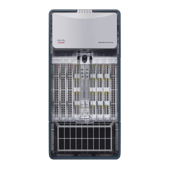
Page 33: Cisco Nexus 7010 System
(15 RU if you use the bottom support rails, which are required for center-mount installations and optional for front-mount installations). Install the Cisco Nexus 7009 chassis at the lowest possible RU on the rack for stability. If there are other devices in the rack, install the heaviest chassis below the lighter chassis. - Page 34 Chapter 1 Overview Cisco Nexus 7000 Series Figure 1-4 Standard Hardware Features on the Front and Sides of the Cisco Nexus 7010 Chassis Cisco Nexus 7000 Series Hardware Installation and Reference Guide 1-10 OL-23069-07...
- Page 35 1. The Cisco Nexus F2-Series 48-port 1/10-Gigabit SFP+ module supports all of the standard features of F2 modules and it functions like an F2-series module with Layer 2 and Layer 3 enabled. These modules also support IPv6 DSCP-to-Queue mapping.
- Page 36 Chapter 1 Overview Cisco Nexus 7000 Series Figure 1-5 Optional Hardware Features on the Front Side of the Cisco Nexus 7010 Chassis Mid-frame door assembly Air filter Cisco Nexus 7000 Series Hardware Installation and Reference Guide 1-12 OL-23069-07...
- Page 37 Figure 1-4 Figure 1-6 show the Cisco Nexus 7000 Series chassis as it appears when it is fully Note configured before including cables for connections to the Internet and the console. The systems that are...
- Page 38 Chapter 1 Overview Cisco Nexus 7000 Series You must install the Cisco Nexus 7010 system chassis in a four-post 19-inch EIA rack that meets the following specifications: • Mounting rails that conform to the English universal hole spacing as specified in ANSI/EIA-310-D-1992.
-
Page 39: Cisco Nexus 7018 System
Cisco Nexus 7018 System The Cisco Nexus 7018 chassis has 18 slots that allow for two supervisor modules and up to 16 I/O modules. The chassis also holds up to five fabric modules, two fan trays, up to four power supplies, and a cable management system. - Page 40 Chapter 1 Overview Cisco Nexus 7000 Series Figure 1-9 Standard Hardware Features on the Front and Sides of the Cisco Nexus 7018 Chassis Cisco Nexus 7000 Series Hardware Installation and Reference Guide 1-16 OL-23069-07...
- Page 41 Supervisor 1 (N7K-SUP1) • Supervisor 2 (N7K-SUP2) • Supervisor 2 Enhanced (N7K-SUP2E) • Cisco Nexus 7000 Series Hardware Installation and Reference Guide 1-17 OL-23069-07...
- Page 42 Cisco Nexus 7000 Series 1. The Cisco Nexus F2-Series 48-port 1/10-Gigabit SFP+ module supports all of the standard features of F2 modules and it functions like an F2-series module with Layer 2 and Layer 3 enabled. These modules also support IPv6 DSCP-to-Queue mapping.
- Page 43 Chapter 1 Overview Cisco Nexus 7000 Series Figure 1-11 Optional Front Door for the Cisco Nexus 7018 Chassis Front doors Air intake frame for power supply units Cisco Nexus 7000 Series Hardware Installation and Reference Guide 1-19 OL-23069-07...
- Page 44 Chapter 1 Overview Cisco Nexus 7000 Series Figure 1-12 Standard Hardware Features on the Back of the Cisco Nexus 7018 Chassis Cisco Nexus 7000 Series Hardware Installation and Reference Guide 1-20 OL-23069-07...
- Page 45 • chassis installation and 87.5 inches (222.2 cm). Install the Cisco Nexus 7018 chassis at the lowest possible RU on the rack for stability, as shown in Figure 1-13. If there is another device in the rack, install the heaviest one at the bottom.
-
Page 46: Preparing The Site
Installation of the equipment must comply with local and national electrical codes. Statement 1074 Before you can install a Cisco Nexus 7000 Series system, you must prepare the site for the installation. You must make sure that the altitude, temperature, humidity, air quality, airflow, electromagnetic and radio frequency interference, floor structure, power, and earth grounding of the installation site all meet the requirements of the Cisco Nexus 7000 Series system that you are installing. -
Page 47: Safety Guidelines
Chapter 7, “Connecting the Cisco Nexus 7000 Series Switch to the Network.” Do not use the handles on the side of the chassis to lift the Cisco Nexus 7009, 7010, or 7018 chassis or Caution a fully loaded Cisco Nexus 7004 chassis (you can use these handles to lift a Cisco Nexus 7004 chassis if you remove the power supplies so that the chassis weighs less than 120 pounds [52 kg]). -
Page 48: Managing The System Hardware
Managing the System Hardware If you are replacing Fabric 1 modules with Fabric 2 modules (Cisco Nexus 7010 and 7018 models only), you must replace all of the Fabric 1 modules with Fabric 2 modules or the Fabric 2 modules will perform like Fabric 1 modules. -
Page 49: Installing A Cisco Nexus 7009 Chassis
Installing a Cisco Nexus 7004 Chassis This chapter describes how to install a new or relocated Cisco Nexus 7004 chassis in a rack or cabinet. For information about installing other Cisco Nexus 7000 Series chassis or power supplies, see the following chapters: Chapter 3, “Installing a Cisco Nexus 7009 Chassis”... -
Page 50: Chapter 2 Installing A Cisco Nexu 7004 Chassi
Preparing to Install the Switch Required Tools Before you install the Cisco Nexus 7004 chassis into a rack, make sure that you have the Cisco Nexus 7004 Accessory Kit (see the “Cisco Nexus 7004 Switch Accessory Kit” section on page C-1... -
Page 51: Unpacking And Inspecting A New Switch
Before you install a new Cisco Nexus 7004 chassis, you need to unpack and inspect it to be sure that you have all the items that you ordered and verify that the switch was not damaged during shipment. If anything is damaged or missing, contact your customer representative immediately. -
Page 52: Installing The Chassis
• Installing the Chassis This section describes how to install the Cisco Nexus 7004 chassis in a rack or cabinet. These installation steps include checking for installation prerequisites, setting up the center-mount brackets if needed, removing the power supplies from the chassis if lifting the chassis manually, and installing the chassis in a rack. -
Page 53: Installing The Center-Mount Brackets
Installing the Center-Mount Brackets Before you install a Cisco Nexus 7004 chassis, you need to determine whether you need to mount the front of the chassis or the center of the chassis to the rack. The chassis is already set up for mounting its front to the rack, but you can include center-mount brackets to position the front of the chassis 5.7 inches... -
Page 54: Installing The Chassis In A Rack
You can either lift the chassis with a mechanical lift and slide it on top of another installed Cisco Nexus 7004 chassis, or you can lighten the chassis and lift it manually into position with a couple of people. To lighten the chassis for lifting, you can remove the power supplies so that the chassis weighs no more than 93 pounds (42 kg) and can be lifted by two people. - Page 55 Lift the chassis to its position on a rack in one of the following ways: Step 2 If you use a mechanical lift, position the chassis next to the front of another Cisco Nexus 7004 • chassis already installed in the rack, elevate the new chassis to the level of the installed chassis (or no more than 0.25 inches [0.64 cm] above the installed chassis, use two persons to align the back...
- Page 56 “Installing a 3-kW AC Power Supply Unit During Operations” section on page 10-3. • To install a DC power supply unit, see the “Installing a 3-kW DC Power Supply Unit During Operations” section on page 10-10. Cisco Nexus 7000 Series Hardware Installation and Reference Guide OL-23069-07...
-
Page 57: Grounding The Cisco Nexus 7004 Chassis
Grounding the Cisco Nexus 7004 Chassis Grounding the Cisco Nexus 7004 Chassis The Cisco Nexus 7004 switch is fully grounded as soon as you connect the chassis and the power supplies to the earth ground in the following ways: You connect the chassis to either a grounded and fully bonded rack or to the data center ground. This •... - Page 58 Be sure that the grounding lug and wire do not block the ESD port by positioning the lug and wire Note connection above the grounding port. Figure 2-4 Grounding Pad and ESD Port Locations on the Cisco Nexus 7004 Chassis Grounding pad ESD port Cisco Nexus 7000 Series Hardware Installation and Reference Guide...
-
Page 59: Installing The Cable Management Frames
The top of the frame should be at the same level as the top of the chassis (see Figure 2-5). Cisco Nexus 7000 Series Hardware Installation and Reference Guide 2-11 OL-23069-07... -
Page 60: Installing Usb Storage Media In A Supervisor 2 Or 2E Module
Installing USB Storage Media in a Supervisor 2 or 2E Module Each Supervisor 2 or 2E module on a Cisco Nexus 7004 switch has a USB drive installed in the LOG FLASH reader. The Slot0 port is left empty, but you can optionally install a USB drive in the that port. -
Page 61: Installing The Air Filter
USB drive with another that is properly formatted for the reader. Installing the Air Filter The Cisco Nexus 7004 air filter is an optional feature (part number N7K-C7004-FAN=). To install an air filter, follow these steps: Place the air filter over the air intake area on the right side of the chassis and align the eight screw holes Step 1 in the filter to screw holes in the chassis. - Page 62 Chapter 2 Installing a Cisco Nexus 7004 Chassis Installing the Air Filter Cisco Nexus 7000 Series Hardware Installation and Reference Guide 2-14 OL-23069-07...
-
Page 63: Preparing To Install The Switch
• Note You must set up a two- or four-post, 19-inch EIA rack or cabinet before you can install the Cisco Nexus 7009 chassis. Make sure that you order the rack or cabinet and have it delivered before installing the chassis. -
Page 64: Preparing To Install The Switch
Installing a Cisco Nexus 7009 Chassis Preparing to Install the Switch Required Tools Before you install the Cisco Nexus 7009 chassis into a rack, make sure that you have the following tools and equipment: • Mechanical lift capable of lifting 300 pounds (136 kg) •... -
Page 65: Unpacking And Inspecting A New Switch
Unpacking and Inspecting a New Switch Before you install a new Cisco Nexus 7009 chassis, you need to unpack and inspect it to be sure that you have all the items that you ordered and verify that the switch was not damaged during shipment. If anything is damaged or missing, contact your customer representative immediately. -
Page 66: Installing The Bottom-Support Rails On The Rack
This process enables you to install three 14-RU Cisco Nexus 7009 chassis in a 42-RU rack. If you do not need to install three chassis in a 42 RU rack, we recommend that you always install each chassis on its own set of bottom-support rails. -
Page 67: Prerequisites For Attaching The Bottom-Support Rails
To maximize the stability of the rack, install everything as low as possible on the rack with heavier items below lighter items. Be sure that there is 15 RU available for installing the Cisco Nexus 7009 chassis (14 RU) and its bottom-support rack (1 RU). Required Tools and Equipment You need the following tools and equipment to attach the bottom-support rails: Number 1 Phillips-head screwdriver with torque capability. -
Page 68: Attaching The Front-Mount Bottom-Support Rails
Position one of the two front-mount bottom-support rails at the lowest possible RU on the rack. If you Step 1 are installing a chassis above another Cisco Nexus 7009 chassis, position the rail 26.25 inches (66.7 cm) (15 RU) above the bottom-support rails for the lower chassis as shown in Figure 3-1. - Page 69 M6 x 19 mm or 12-24 x 3/4 in. Phillips screws on the front end of each bracket (using a total of 6 screws for both brackets) as shown in Figure 3-2. Cisco Nexus 7000 Series Hardware Installation and Reference Guide OL-23069-07...
-
Page 70: Attaching The Center-Mount Bottom-Support Rails
If you install a second chassis in the same rack, install it immediately above the lower system if there is enough vertical space. Cisco Nexus 7000 Series Hardware Installation and Reference Guide OL-23069-07... - Page 71 Position one of the two center-mount brackets at the lowest possible RU. If you are installing a chassis above another Cisco Nexus 7009 chassis, position the rail 26.25 inches (66.7 cm) (15 RU) above the center-mount bottom-support rails for the lower chassis as shown in Figure 3-3.
- Page 72 Align the crossbar to the lower back of the two bottom-support rails and use two M4 x 8 mm screws to Step 3 attach it to each rail (one screw for each rail). Cisco Nexus 7000 Series Hardware Installation and Reference Guide 3-10 OL-23069-07...
-
Page 73: Installing The Chassis
Installing the Chassis This section describes how to install the Cisco Nexus 7009 chassis in a rack or cabinet. Depending on your data center requirements, you can choose to mount the front of the chassis to a rack or cabinet (standard method of mounting the chassis), or you can choose to mount the center of the chassis to a rack or cabinet. -
Page 74: Required Tools And Equipment
“Unpacking and Inspecting a New Switch” section on page 3-3. Required Tools and Equipment You need the following tools and equipment to install the Cisco Nexus 7009 chassis: Mechanical lift capable of lifting at least 300 pounds (136 kg) •... -
Page 75: Mounting The Chassis By Its Front Brackets
Center-mount bottom-support rails Center-mount bracket Mounting the Chassis by its Front Brackets To install a Cisco Nexus 7009 chassis by its front brackets to a rack or cabinet, follow these steps: Step 1 Load the chassis onto a mechanical lift as follows: Position the mechanical lift next to the shipping pallet that holds the chassis. - Page 76 Installing a Cisco Nexus 7009 Chassis Installing the Chassis Figure 3-5 Moving a Cisco Nexus 7009 Chassis onto a Rack (Front-Mount Installation) Push the lower half of the front side of the chassis 3 Rack with vertical mounting rails Front-mounting brackets...
-
Page 77: Mounting The Chassis By Its Center Brackets
Mounting the Chassis by its Center Brackets To install a Cisco Nexus 7009 chassis by its optional center bracket to a rack or cabinet, follow these steps: Follow these steps to replace the front-mount bracket on the chassis with center-mount brackets:... - Page 78 Remove the bracket from the chassis Position the center-mount bracket so that its five screw holes are aligned to the five screw holes used for the front-mount bracket (see Figure 3-8). Cisco Nexus 7000 Series Hardware Installation and Reference Guide 3-16 OL-23069-07...
- Page 79 Make sure that the front and rear of the chassis are unobstructed so you can easily push the chassis into the rack. Cisco Nexus 7000 Series Hardware Installation and Reference Guide 3-17...
- Page 80 (See Figure 3-9.) Figure 3-9 Moving a Cisco Nexus 7009 Chassis onto a Rack (Center-Mount Installation) Push the lower half of the front side of the chassis 3 Rack with vertical mount rails Center-mount brackets...
-
Page 81: Grounding The Cisco Nexus 7009 Chassis
Grounding the Cisco Nexus 7009 Chassis If you are using AC power supply units, the Cisco Nexus 7009 system is grounded through the AC power supply cables and one of two grounding connections on the chassis. The AC power supply cables provide a connection to an earth ground whenever you connect the AC power to the system. -
Page 82: Prerequisites For Grounding The Chassis
Before you can ground the chassis, you must have a connection to the earth ground for the data center building. If you installed the Cisco Nexus 7009 chassis into a bonded rack (see the rack manufacturer’s instructions for more information) that now has a connection to the data center earth ground, you can ground the chassis by connecting its grounding ports to the rack. - Page 83 Ensure that the grounding lug and the grounding wire do not interfere with other switch hardware or rack equipment. Cisco Nexus 7000 Series Hardware Installation and Reference Guide 3-21 OL-23069-07...
- Page 84 Grounding the Cisco Nexus 7009 Chassis Figure 3-12 Grounding Pad on the Front of the Cisco Nexus 7009 Chassis Grounding pad Prepare the other end of the grounding wire and connect it to an appropriate grounding point in your site to ensure an adequate earth ground for the switch.
-
Page 85: Connecting Your Esd Wrist Strap To The Chassis
After you connect the chassis to the data center earth ground, you can ground your ESD wrist strap by plugging it into an ESD port (shown in Figure 3-13). Figure 3-13 ESD Grounding Port on the Front of the Cisco Nexus 7009 Chassis ESD grounding port Cisco Nexus 7000 Series Hardware Installation and Reference Guide 3-23 OL-23069-07... -
Page 86: Installing The Cable Management Frames
Installing the Cable Management Frames Installing the Cable Management Frames After you have fully installed the Cisco Nexus 7009 switch chassis in the rack or cabinet (see the “Installing the Chassis” section on page 3-11), you can install the cable management frames on the front of the chassis. - Page 87 Push the top hood toward the chassis so that its alignment pins enter the alignment holes and the top hood rests against the chassis as shown in Figure 3-15. Cisco Nexus 7000 Series Hardware Installation and Reference Guide 3-25 OL-23069-07...
- Page 88 Fastening the Top Hood to the Chassis and Cable Management Assemblies Four M4x8 pan-head screws that fasten the top hood to the left and right cable management assemblies (two screws for each side). Cisco Nexus 7000 Series Hardware Installation and Reference Guide 3-26 OL-23069-07...
-
Page 89: Installing The Front Door And Air Intake Frame
If you need to install the optional double-hinged door and air intake frame, you must install them after installing the cable management frame on the chassis. To install the front door and air intake frame to the Cisco Nexus 7009 cable management system, follow these steps:... - Page 90 Step 3 Assemble the two pieces of the right door stop over the bushings and post. Fasten the two pieces together with two M4 flathead screws (see Figure 3-19). Cisco Nexus 7000 Series Hardware Installation and Reference Guide 3-28 OL-23069-07...
- Page 91 3-20. Push the hinge bracket to the chassis so that the pins go into the chassis. Two screw holes in each of the cable management side frames should align to screw holes in the hinge bracket. Cisco Nexus 7000 Series Hardware Installation and Reference Guide 3-29 OL-23069-07...
- Page 92 Positioning the Hinge Bracket to the Cable Management Frames and Chassis Alignment pins Alignment holes Attach the bracket to the chassis and cable management frames with eight loosely fastened M4x8 screws, Step 5 as shown in Figure 3-21. Cisco Nexus 7000 Series Hardware Installation and Reference Guide 3-30 OL-23069-07...
- Page 93 Align the two captive screws on the air intake frame to the two screw holes below the cable management Step 8 frames on the chassis as shown in Figure 3-22. Cisco Nexus 7000 Series Hardware Installation and Reference Guide 3-31 OL-23069-07...
- Page 94 The double-hinge door can be installed and opened on either side. The figures in this procedure show how to install the door on the left side first, but you can use the instructions to install it on either side. Cisco Nexus 7000 Series Hardware Installation and Reference Guide 3-32...
- Page 95 3-24. This action locks the latches around the hinge pins so that you no longer need to hold the door onto the chassis. Figure 3-24 Attaching the Left Side of the Door Cisco Nexus 7000 Series Hardware Installation and Reference Guide 3-33 OL-23069-07...
- Page 96 See Figure 3-25. Figure 3-25 Attaching the Right Side of the Door Door handle pulled out until it clicks Door closed onto the hinge pins Hinge pins Cisco Nexus 7000 Series Hardware Installation and Reference Guide 3-34 OL-23069-07...
-
Page 97: Installing Storage Media In A Supervisor Module
Installing Storage Media in a Supervisor Module Each supervisor module on a Cisco Nexus 7000 Series switch is shipped with a CompactFlash card installed in the LOG FLASH reader (Supervisor 1 modules) or a USB drive installed in the LOG FLASH reader (Supervisor 2 and Supervisor 2E modules). - Page 98 Make sure that the card or USB drive is fully inserted inside the reader. If it is fully inserted, either format the card (see the Cisco Nexus 7000 Series NX-OS Fundamentals Configuration Guide) or replace the storage media with another that is properly formatted for the reader.
-
Page 99: Preparing To Install The Switch
Installing a Cisco Nexus 7010 Chassis This chapter describes how to install a new or relocated Cisco Nexus 7010 chassis in a rack or cabinet. For information about installing other Cisco Nexus 7000 Series chassis or power supplies, see the following chapters: Chapter 2, “Installing a Cisco Nexus 7004 Chassis”... -
Page 100: Preparing To Install The Switch
Installing a Cisco Nexus 7010 Chassis Preparing to Install the Switch Required Tools Before you install the Cisco Nexus 7010 chassis into a rack, make sure that you have the following tools and equipment: • Mechanical lift capable of lifting 550 pounds (250 kg) •... -
Page 101: Unpacking And Inspecting A New Switch
Unpacking and Inspecting a New Switch Before you install a new Cisco Nexus 7010 chassis, you need to unpack and inspect it to be sure that you have all the items that you ordered and verify that the switch was not damaged during shipment. If anything is damaged or missing, contact your customer representative immediately. -
Page 102: Installing The Bottom-Support Rails On The Rack
Installing the Bottom-Support Rails on the Rack The bottom-support rails hold the Cisco Nexus 7010 chassis on the rack or cabinet. To maximize the stability of the rack, you must attach these rails at the lowest possible rack unit (RU). - Page 103 Position one of the two adjustable bottom-support rails at the lowest possible RU. If you are installing a chassis above another Cisco Nexus 7010 chassis, position the rail 36.75 inches (93.4 cm) (21 RU) above the bottom-support rails for the lower chassis as shown in Figure 4-1.
- Page 104 Three of the screw holes on each end of the bottom-support rail align to the screw holes in the mounting Note rail. Use a screw in each of these screw holes. Cisco Nexus 7000 Series Hardware Installation and Reference Guide OL-23069-07...
-
Page 105: Installing The Chassis
3 12-24 x 3/4 in. Phillips screws Installing the Chassis This section describes how to install the Cisco Nexus 7010 chassis in a rack or cabinet. These installation steps include transporting the chassis, elevating the chassis to the rack using a mechanical lift, pushing the chassis onto the rack, and then securing the chassis to the rack. -
Page 106: Required Tools And Equipment
“Unpacking and Inspecting a New Switch” section on page 4-3. Required Tools and Equipment You need the following tools and equipment to install the Cisco Nexus 7010 chassis: Mechanical lift capable of lifting at least 550 pounds (250 kg) •... -
Page 107: Installing The Chassis
Note kg), onto and off the mechanical lift and rack. Installing the Chassis To install a Cisco Nexus 7010 chassis in a four-post rack or cabinet, follow these steps: Load the chassis onto a mechanical lift as follows: Step 1 Position the mechanical lift next to the shipping pallet that holds the chassis. - Page 108 Use a Phillips screwdriver to screw in four M6 x 19-mm or 12-24 x 3/4-inch screws in each of the two chassis mounting brackets (use a total of eight screws for two mounting brackets) as shown in Figure 4-4. Cisco Nexus 7000 Series Hardware Installation and Reference Guide 4-10 OL-23069-07...
-
Page 109: Grounding The Cisco Nexus 7010 Chassis
Grounding the Cisco Nexus 7010 Chassis The Cisco Nexus 7010 system is grounded through the AC power supply cables and one of two grounding connections on the chassis. The AC power supply cables provide a connection to an earth ground whenever you connect the AC power to the system. -
Page 110: Prerequisites For Grounding The Chassis
Before you can ground the chassis, you must have a connection to the earth ground for the data center building. If you installed the Cisco Nexus 7010 chassis into a bonded rack (see the rack manufacturer’s instructions for more information) that now has a connection to the data center earth ground, you can ground the chassis by connecting its grounding ports to the rack. - Page 111 Figure 4-6 Grounding Pad on the Front of the Cisco Nexus 7010 Chassis Grounding pad Cisco Nexus 7000 Series Hardware Installation and Reference Guide...
-
Page 112: Connecting Your Esd Wrist Strap To The Chassis
Installing a Cisco Nexus 7010 Chassis Grounding the Cisco Nexus 7010 Chassis Figure 4-7 Grounding Pad on the Rear of the Cisco Nexus 7010 Chassis Grounding pad Step 5 Prepare the other end of the grounding wire and connect it to an appropriate grounding point in your site to ensure an adequate earth ground for the switch. - Page 113 Chapter 4 Installing a Cisco Nexus 7010 Chassis Grounding the Cisco Nexus 7010 Chassis Figure 4-8 ESD Grounding Ports on the Front of the Cisco Nexus 7010 Chassis ESD grounding port Cisco Nexus 7000 Series Hardware Installation and Reference Guide 4-15...
-
Page 114: Installing Storage Media In A Supervisor Module
Installing Storage Media in a Supervisor Module Each supervisor module on a Cisco Nexus 7000 Series switch is shipped with a CompactFlash card installed in the LOG FLASH reader (Supervisor 1 modules) or a USB drive installed in the LOG FLASH reader (Supervisor 2 and Supervisor 2E modules). -
Page 115: Installing The Front Doors And Frame Assembly
Make sure that the card or USB drive is fully inserted inside the reader. If it is fully inserted, either format the card (see the Cisco Nexus 7000 Series NX-OS Fundamentals Configuration Guide) or replace the storage media with another that is properly formatted for the reader. - Page 116 For each of the two front doors, match the two alignment pins on the door frame to the alignment holes on the chassis. Position each door frame immediately under the cable management area (see Figure 4-12). Cisco Nexus 7000 Series Hardware Installation and Reference Guide 4-18 OL-23069-07...
- Page 117 Place door frame on front edge of chassis and immediately under the cable management area. Cable management area. Tighten three screws for each door frame (see Figure 4-13). Step 3 Cisco Nexus 7000 Series Hardware Installation and Reference Guide 4-19 OL-23069-07...
- Page 118 Remove the EMI panel by unscrewing its four captive screws until each is free of the chassis (see Figure 4-14). Cisco Nexus 7000 Series Hardware Installation and Reference Guide 4-20 OL-23069-07...
- Page 119 EMI panel. Screw in a screw in each of these two screw holes so that the side frame assembly is attached to the EMI panel. Repeat this step for the other side of the EMI panel. See Figure 4-15. Cisco Nexus 7000 Series Hardware Installation and Reference Guide 4-21 OL-23069-07...
- Page 120 Realign the EMI panel to the air intake area on the chassis, screw its four captive screws to the chassis, and tighten the captive screws to 8 in-lb (0.9 N·m). Cisco Nexus 7000 Series Hardware Installation and Reference Guide 4-22...
-
Page 121: Installing The Air Filter
Installing a Cisco Nexus 7010 Chassis Installing the Air Filter Installing the Air Filter You can install the optional air filter while the Cisco Nexus 7000 Series system is operational. Only the Cisco Nexus 7010 switch includes an optional air filter. Note... - Page 122 Chapter 4 Installing a Cisco Nexus 7010 Chassis Installing the Air Filter Cisco Nexus 7000 Series Hardware Installation and Reference Guide 4-24 OL-23069-07...
- Page 123 Installing a Cisco Nexus 7018 Chassis This chapter describes how to install a new or relocated Cisco Nexus 7018 chassis in a rack or cabinet. For information about installing other Cisco Nexus 7000 Series chassis or power supplies, see the following chapters: Chapter 2, “Installing a Cisco Nexus 7004 Chassis”...
-
Page 124: Preparing To Install The Switch
Installing a Cisco Nexus 7018 Chassis Preparing to Install the Switch Required Tools Before you install the Cisco Nexus 7018 chassis into a rack, make sure that you have the following tools and equipment: • Mechanical lift capable of lifting 700 pounds (318 kg... -
Page 125: Unpacking And Inspecting A New Chassis
Unpacking and Inspecting a New Chassis Before you install a new Cisco Nexus 7018 chassis, you need to unpack and inspect it to be sure that you have all the items that you ordered and verify that the switch was not damaged during shipment. If anything is damaged or missing, contact your customer representative immediately. -
Page 126: Installing The Bottom-Support Rails On The Rack
Installing the Bottom-Support Rails on the Rack The bottom-support rails hold the Cisco Nexus 7018 chassis on the rack or cabinet. To maximize the stability of the rack, you must attach these rails at the lowest possible rack unit (RU). - Page 127 Make sure that the two bottom-support rails are level with one another. If they are not level, adjust the Note higher rail down to the level of the lower rail. Cisco Nexus 7000 Series Hardware Installation and Reference Guide OL-23069-07...
- Page 128 Phillips screws on each end of each rail (using a total of 16 screws for both brackets) as shown in Figure 5-2. Tighten each screw to a maximum of 40 in-lb [4.5 N·m]) of torque. Cisco Nexus 7000 Series Hardware Installation and Reference Guide OL-23069-07...
-
Page 129: Installing The Chassis
Before you install the chassis, you must make sure that the following items are available for the installation: Data center ground is accessible where you are installing the Cisco Nexus 7018 chassis. • Four-post, 19-inch EIA rack or cabinet that includes such a rack. -
Page 130: Required Tools And Equipment
“Unpacking and Inspecting a New Chassis” section on page 5-3. Required Tools and Equipment You need the following tools and equipment to install the Cisco Nexus 7000 Series chassis: Mechanical lift capable of lifting 700 pounds (318 kg) • You must use a mechanical lift to lift a switch weighing over 120 pounds (55 kg). -
Page 131: Installing The Chassis
Installing the Chassis To install a Cisco Nexus 7018 chassis in a four-post rack or cabinet, follow these steps: To lighten the chassis, we recommend that you remove the fan trays from the chassis. The electronics on Step 1 these modules are well sealed from damage but you must still be careful not to damage their connectors. - Page 132 Use the third person to be sure that the back end of the chassis does not get caught on the expansion edge of the bottom support rails. Cisco Nexus 7000 Series Hardware Installation and Reference Guide 5-10 OL-23069-07...
- Page 133 Make sure that the screw holes in the chassis mounting brackets align with the screw holes in the vertical Step 7 mounting rails. If you need to reposition the chassis to align the screw holes, you can use the handles on the sides of the chassis. Cisco Nexus 7000 Series Hardware Installation and Reference Guide 5-11 OL-23069-07...
- Page 134 (use a total of 18 screws for two mounting brackets) as shown in Figure 5-4. Tighten each screw to a maximum of 40 in-lb [4.5 N·m] of torque. Figure 5-4 Attaching the Cisco Nexus 7018 Chassis to the Rack Cisco Nexus 7000 Series Hardware Installation and Reference Guide 5-12 OL-23069-07...
-
Page 135: Grounding The Cisco Nexus 7018 Chassis
(use a total of 18 screws) Grounding the Cisco Nexus 7018 Chassis The Cisco Nexus 7018 system is grounded through the AC power supply cables and one of two grounding connections on the chassis. The AC power supply cables provide a connection to an earth ground whenever you connect the AC power to the system. -
Page 136: Connecting The System Ground
Ensure that the grounding lug and the grounding wire do not interfere with other switch hardware or rack equipment. Cisco Nexus 7000 Series Hardware Installation and Reference Guide 5-14 OL-23069-07... -
Page 137: Connecting Your Esd Wrist Strap To The Chassis
Connecting Your ESD Wrist Strap to the Chassis After you connect the chassis to the earth ground, you can ground your ESD wrist strap by plugging it into the ESD port shown in Figure 5-7. Cisco Nexus 7000 Series Hardware Installation and Reference Guide 5-15 OL-23069-07... -
Page 138: Installing The Cable Management Frame
ESD grounding port Installing the Cable Management Frame After you have fully installed the Cisco Nexus 7018 switch chassis in the rack or cabinet (see the “Installing the Chassis” section on page 5-7), you can install the cable management frame on the front of the chassis. - Page 139 Attach a lower cable management assembly (800-31343-01) onto the two hooks that protrude from the Step 1 lower half of the left rack-mount bracket that is attached to the Cisco Nexus 7018 switch chassis, and loosely fasten the assembly to the chassis with four flat-head M4x10 screws as shown in Figure 5-8.
- Page 140 Attach an upper cable management assembly (800-31342-01) onto the two hooks that protrude from the Step 3 upper half of the left rack-mount bracket that is attached to the Cisco Nexus 7018 switch chassis, and loosely fasten the assembly to the chassis with four flat-head M4x10 screws as shown in Figure 5-9.
- Page 141 Figure 5-11. Push the top hood toward the chassis so that its alignment pins enter the alignment holes and the top hood rests against the chassis. Cisco Nexus 7000 Series Hardware Installation and Reference Guide 5-19 OL-23069-07...
- Page 142 Positioning the Top Hood with the Upper Cable Management Assemblies and the Switch Chassis Alignment pins Alignment holes Use four M4x8 pan-head screws to loosely fasten the top hood to the chassis as shown in Figure 5-12. Step 6 Cisco Nexus 7000 Series Hardware Installation and Reference Guide 5-20 OL-23069-07...
-
Page 143: Installing The Front Door And Air Intake Frame
Also, make sure that the cable management frame is aligned to the vertical sides of the chassis and that the cable management hood is level when you install those components. Cisco Nexus 7000 Series Hardware Installation and Reference Guide 5-21... - Page 144 Installing a Cisco Nexus 7018 Chassis Installing the Front Door and Air Intake Frame To install the front door and air intake frame to the Cisco Nexus 7018 cable management system, follow these steps: Position the left door stopper (700-27454-01) on the middle of the left cable management frame and...
- Page 145 Position the hinge bracket (700-28491-01) at the bottom of the cable management frame and the chassis Step 3 as shown in Figure 5-15. Cisco Nexus 7000 Series Hardware Installation and Reference Guide 5-23 OL-23069-07...
- Page 146 Positioning the Hinge Bracket to the Cable Management Frame and Chassis Alignment pins Alignment holes Attach the bracket to the chassis with eight loosely fastened M4x8 screws, as shown in Figure 5-16. Step 4 Cisco Nexus 7000 Series Hardware Installation and Reference Guide 5-24 OL-23069-07...
- Page 147 Fasten the four ball-point studs (51-5008-01), each one with a washer (49-0430-01), to the bottom Step 7 portion of the chassis, one stud by each corner of the air intake area as shown in Figure 5-17. Cisco Nexus 7000 Series Hardware Installation and Reference Guide 5-25 OL-23069-07...
- Page 148 Align the air intake frame to the four ball-point studs and press the frame onto the chassis as shown in Step 8 Figure 5-18. The captive screws on the air-intake frame should align with their screw holes in the chassis. Cisco Nexus 7000 Series Hardware Installation and Reference Guide 5-26 OL-23069-07...
- Page 149 The double-hinge door can be installed and opened on either side. The figures in this procedure show Note how to install the door on the left side first, but you can use the instructions to install it on either side. Cisco Nexus 7000 Series Hardware Installation and Reference Guide 5-27 OL-23069-07...
- Page 150 See Figure 5-20. This action locks the latches around the hinge pins so that you no longer need to hold the door onto the chassis. Cisco Nexus 7000 Series Hardware Installation and Reference Guide 5-28 OL-23069-07...
- Page 151 Open the door handle on the open side of the door until it clicks. This action opens the latches on the Step 13 open side of the door. See Figure 5-21. Cisco Nexus 7000 Series Hardware Installation and Reference Guide 5-29 OL-23069-07...
- Page 152 If you do not hear the latches click, press the door at the handle to fully close it and to activate the latches. Test the door to make sure that it is fully secured to the four hinge pins. Cisco Nexus 7000 Series Hardware Installation and Reference Guide 5-30...
-
Page 153: Installing Storage Media In A Supervisor Module
Installing Storage Media in a Supervisor Module Each supervisor module on a Cisco Nexus 7000 Series switch is shipped with a CompactFlash card installed in the LOG FLASH reader (Supervisor 1 modules) or a USB drive installed in the LOG FLASH reader (Supervisor 2 and Supervisor 2E modules). - Page 154 Make sure that the card or USB drive is fully inserted inside the reader. If it is fully inserted, either format the card (see the Cisco Nexus 7000 Series NX-OS Fundamentals Configuration Guide) or replace the storage media with another that is properly formatted for the reader.
-
Page 155: Chapter 6 Installing Power Supplies
Installing Power Supplies This chapter describes how to install AC and DC power supplies in any Cisco Nexus 7000 Series chassis. The AC power supplies convert the AC power from your facility to DC power for use in the chassis; the DC power supplies take DC power from your facility for use in the chassis. -
Page 156: Installing Power Supplies
Installing Power Supplies You can install two or more power supplies in each Cisco Nexus 7000 Series chassis. If you leave any power supply slots empty, you must install a blank filler plate in those slots to maintain the designed airflow. -
Page 157: Connecting An Ac Power Supply To Ac Power Sources
Connecting an AC Power Supply to AC Power Sources If you are powering your Cisco Nexus 7000 Series switch with 3-, 6-, or 7.5-kW AC power supplies, you must connect those power supplies to an AC power source. When you connect the power cable to the AC power grid and the power supply, the power supply is automatically grounded through this cable. - Page 158 (see Appendix C, “Accessory Kits Contents”). If you do not have the correct cables, contact Cisco TAC. Warning Read the installation instructions before connecting the system to the power source. Statement 1004 This section includes the following topics: •...
-
Page 159: Prerequisites For Connecting Ac Power Supplies To Ac Power Sources
250V, 20 A Statement 1005 Step 4 Turn the power supply switch from standby to on (from 0 to 1 as labelled on the power switch). Cisco Nexus 7000 Series Hardware Installation and Reference Guide OL-23069-07... -
Page 160: Connecting A 6-Kw Ac Power Supply To Ac Power Sources
INPUT and OUTPUT power supply LEDs are lit and the FAULT LED is not lit or flashing. For an explanation of all the power supply LEDs and the conditions that they indicate, see Table D-6 on page D-6. Cisco Nexus 7000 Series Hardware Installation and Reference Guide OL-23069-07... -
Page 161: Connecting A 7.5-Kw Ac Power Supply To Ac Power Sources
AC power source, and then turn the power switch back to ON. The Input and Output LEDs for the connected power supplies should be green and the Fault LED should be off. Cisco Nexus 7000 Series Hardware Installation and Reference Guide OL-23069-07... -
Page 162: Connecting A Dc Power Supply To Dc Power Sources
Connecting a DC Power Supply to DC Power Sources To power your Cisco Nexus 7000 Series switch with DC power supplies, you must first ground the power supplies and then connect the power supplies to a DC power source. You can then connect the power supply directly to DC power sources or indirectly through a power interface unit (PIU), which is connected to a DC power source. - Page 163 Prepare the other end of the grounding wire and connect it to an appropriate grounding point in your site Step 5 to ensure an adequate earth ground for the power supply. Cisco Nexus 7000 Series Hardware Installation and Reference Guide OL-23069-07...
-
Page 164: Connecting A Dc Power Supply Directly To Dc Power Sources
You configure an extra power supply and you connect all of the power supplies to two grids, as shown in Figure 6-6. Figure 6-3, Figure 6-4, Figure 6-5, and Figure 6-6 show the required power supplies in black and Note optional power supplies in gray. Cisco Nexus 7000 Series Hardware Installation and Reference Guide 6-10 OL-23069-07... - Page 165 (each cable for 3 kW of power) DC power source Connections required for 6 kW of available power Connections required for 3 kW of available power Cisco Nexus 7000 Series Hardware Installation and Reference Guide 6-11 OL-23069-07...
- Page 166 Connection for available power (for a minimum of 3 kW) Redundant power supply Power supply redundancy connection (power connection at least equals the power connection for any power supply providing available power) Cisco Nexus 7000 Series Hardware Installation and Reference Guide 6-12 OL-23069-07...
- Page 167 DC power grid and supply, each power cable connects to a separate the other half connected to another DC power power grid) grid) Two DC power grids Cisco Nexus 7000 Series Hardware Installation and Reference Guide 6-13 OL-23069-07...
- Page 168 (PIU) in a rack where the power cable can connect it to the power supply (see the “Connecting a Power Supply to DC Power Sources through a Power Interface Unit” section on page 6-18). Cisco Nexus 7000 Series Hardware Installation and Reference Guide 6-14 OL-23069-07...
-
Page 169: Connecting A 3-Kw Dc Power Supply Directly To Dc Power Sources
The power cables required for a 6-kW DC power supply are shipped with the power supply. If you did Note not receive the correct cables for a 6-kW DC power supply, contact Cisco TAC. You must supply the power cables for a 3-kW DC power supply. - Page 170 For the powered down circuits connected to the power supplies, turn on the power at the circuit breaker. Step 7 The Input 1 (IN1) and Input 2 (IN2) LEDs turn on each connected power supply. Cisco Nexus 7000 Series Hardware Installation and Reference Guide 6-16 OL-23069-07...
-
Page 171: Connecting A 6-Kw Dc Power Supply To A Dc Power Source
Be sure uninsulated conductors are not accessible when cover is in place. Statement 1075 Connect one or two power cables (Cisco part number N7K-DC-CAB=) to the DC power supply and the Step 4 DC power grid. Each cable has one plug that connects two fully isolated 1.5 kW input modules to a DC power supply for 3 kW of power. -
Page 172: Connecting A Power Supply To Dc Power Sources Through A Power Interface Unit
Turn the power switch on the DC power supply from STBY to ON. The LEDs should flash and then the Step 6 Output LED should turn on in addition to the Input LEDs. If the FAULT LED is lit or flashing, call Cisco TAC for assistance. Connecting a Power Supply to DC Power Sources through a Power Interface Unit... - Page 173 3-kW DC power supply (1 to 4) 6-kW DC power supply (1 to 4) Power Interface Unit (PIU) Connections for 3 kW of available power DC power grid Connections for 6 kW of available power Cisco Nexus 7000 Series Hardware Installation and Reference Guide 6-19 OL-23069-07...
- Page 174 DC power grid Connections for 3 kW of reserve power (power supply redundancy at least equals the power provided by the power supply providing the maximum amount of available power) Cisco Nexus 7000 Series Hardware Installation and Reference Guide 6-20 OL-23069-07...
- Page 175 6-kW DC power supply (1 to 4) Power interface unit (PIU) Connections for 3 kW of available power Two DC power grids Connections for 3 kW of reserve power (input source redundancy) Cisco Nexus 7000 Series Hardware Installation and Reference Guide 6-21 OL-23069-07...
-
Page 176: Required Tools And Equipment
Installing the PIU in a Rack, page 6-23 • Grounding the PIU, page 6-25 • Connecting the DC Power Supply to a Power Source Through a PIU, page 6-26 • Cisco Nexus 7000 Series Hardware Installation and Reference Guide 6-22 OL-23069-07... -
Page 177: Required Tools And Equipment
Installing the PIU in a Rack To install a PIU in a rack, follow these steps: Position and fasten the two mounting brackets in one of four ways shown in Figure 6-12. Step 1 Cisco Nexus 7000 Series Hardware Installation and Reference Guide 6-23 OL-23069-07... - Page 178 Fasten the PIU to the rack using four M6 x 19 mm screws or four 12-24 x 3/4 inch screws, as shown in Step 3 Figure 6-13. Tighten each screw to 40 in-lb (4.5 N·m). Cisco Nexus 7000 Series Hardware Installation and Reference Guide 6-24 OL-23069-07...
-
Page 179: Grounding The Piu
40 in-lb (4.5 N·m). Figure 6-14 shows the location of the grounding pads on the PIU. Ensure that the grounding lug and the grounding wire do not interfere with other PIU equipment. Cisco Nexus 7000 Series Hardware Installation and Reference Guide 6-25 OL-23069-07... -
Page 180: Connecting The Dc Power Supply To A Power Source Through A Piu
PIU, remove 0.75 in. (19 mm) of insulation from the cut end, and reattach the spade connector to the bare ends. Cisco Nexus 7000 Series Hardware Installation and Reference Guide 6-26... - Page 181 Note cable for all positive circuits and use the other color for all negative circuits. Replace the safety cover on the terminal box and fasten it with three screws. Cisco Nexus 7000 Series Hardware Installation and Reference Guide 6-27 OL-23069-07...
- Page 182 Installing Power Supplies Connecting a DC Power Supply to DC Power Sources If you are connecting a 6-kW DC power supply, insert the plug end of one or two power cables (Cisco Step 5 part number N7K-DC-CAB=) to the power receptacles on the power supply and tighten its two screws to 11 to 15 in-lb (1.2 to 1.7 N·m).
- Page 183 If the wire is not stripped of its insulation for the last 0.75 inches (19 mm), use wire strippers to remove that amount of insulation from the end of the wire. Cisco Nexus 7000 Series Hardware Installation and Reference Guide 6-29...
- Page 184 (labelled as ON or 1). The LEDs should flash and then the Output LEDs should turn on in addition to the Input LEDs. If the FAULT LED is lit or flashing, call Cisco TAC for assistance. Cisco Nexus 7000 Series Hardware Installation and Reference Guide...
-
Page 185: Preparing For Connections
Connecting the Cisco Nexus 7000 Series Switch to the Network This chapter describes how to connect the Cisco Nexus 7000 Series switch (configure its IP address through a console, set up its management interface, and connect its Ethernet ports to the network) after it has been installed in its rack or cabinet. -
Page 186: C H A P T E R 7 Connecting The Cisco Nexus 7000 Series Switch To The Network
COM1/AUX SERIAL PORT—Use this port if you are using a modem (available with only • Supervisor 1). You can find this cable in the console cable connector kit, which is part of the accessory kit for the Cisco Nexus 7000 Series switch. Cisco Nexus 7000 Series Hardware Installation and Reference Guide... -
Page 187: Creating An Initial Switch Configuration
IP address. You can perform the other configurations at a later time as described in the Cisco Nexus 7000 Series NX-OS Fundamentals Configuration Guide, Release 6.x. Before you perform the initial switch configuration, you must determine the IP address and netmask... -
Page 188: Setting Up The Management Interface
The software asks if you need to save the configuration. Enter yes to save the configuration. Step 8 You can now set up the management interface for each supervisor module on the Cisco Nexus 7000 Series switch. Setting Up the Management Interface... -
Page 189: Connecting The Supervisor Cmp Port
Step 3 Connecting the Supervisor CMP Port The CMP, which is included on the Cisco Nexus 7000 Series Supervisor 1 module (the CMP is not included on the Supervisor 2 or Supervisor 2E models), is a secondary, lightweight processor that provides a second network interface to the system for use even when the Control Processor (CP) is not reachable. -
Page 190: Connecting An I/O Module
Chapter 7 Connecting the Cisco Nexus 7000 Series Switch to the Network Connecting an I/O Module Connecting an I/O Module After you set up an IP address for the switch and create an out-of-band management connection for the switch, you can connect the copper (1000BASE-T) and fiber-optic (SFP, SFP+, FET, and X2) I/O modules to the network. - Page 191 Chapter 7 Connecting the Cisco Nexus 7000 Series Switch to the Network Connecting an I/O Module Table 7-1 Connectors and Cables Supported by I/O Modules Module Port Type Connector/Transceiver Cable Type 32-port 1- /10-Gigabit Ethernet (N7K-F132XP-15) SFP+ DWDM-SFP-xxxx Fiber optic...
- Page 192 Chapter 7 Connecting the Cisco Nexus 7000 Series Switch to the Network Connecting an I/O Module Table 7-1 Connectors and Cables Supported by I/O Modules (continued) Module Port Type Connector/Transceiver Cable Type 32-port 10-Gigabit Ethernet (N7K-M132XP-12) SFP+ FET-10G Fiber optic...
-
Page 193: Connecting Or Disconnecting A 1000Base-T Port
Chapter 7 Connecting the Cisco Nexus 7000 Series Switch to the Network Connecting an I/O Module Table 7-1 Connectors and Cables Supported by I/O Modules (continued) Module Port Type Connector/Transceiver Cable Type 8-port 10-Gigabit Ethernet (N7K-M108X2-12L) 10GBASE-X X2 X2-10GB-ER Fiber optic... -
Page 194: Connecting A 1000Base-T Port To The Network
Chapter 7 Connecting the Cisco Nexus 7000 Series Switch to the Network Connecting an I/O Module Connecting a 1000BASE-T Port to the Network You can connect a copper network interface cable with an RJ-45 connector to a port on a 48-port 10/100/1000 Ethernet I/O module (N7K-M148GT-11 and N7K-M148GT-11L). -
Page 195: Installing A Transceiver
Insert a dust cover into the port end of the transceiver and place the transceiver on an antistatic mat or Step 4 into a static shielding bag if you plan to return it to your Cisco representative. If another transceiver is not being installed, protect the optical port cage by inserting a clean cover. -
Page 196: Connecting A Fiber-Optic Cable To A Transceiver
Chapter 7 Connecting the Cisco Nexus 7000 Series Switch to the Network Connecting an I/O Module Connecting a Fiber-Optic Cable to a Transceiver To prevent damage to the fiber-optic cables, do not place more tension on them than the rated limit and Caution do not bend them to a radius less than 1 inch (2.54 cm) if there is no tension in the cable or 2 inches (5.08... -
Page 197: Maintaining Transceivers And Fiber-Optic Cables
Chapter 7 Connecting the Cisco Nexus 7000 Series Switch to the Network Connecting an I/O Module Press the release latch on the cable, grasp the connector near the connection point, and gently pull the Step 3 connector from the transceiver. - Page 198 Chapter 7 Connecting the Cisco Nexus 7000 Series Switch to the Network Connecting an I/O Module Cisco Nexus 7000 Series Hardware Installation and Reference Guide 7-14 OL-23069-07...
-
Page 199: Displaying The Switch Hardware Inventory
Displaying the Switch Hardware Inventory You can display information about the field replaceable units (FRUs), including product IDs, serial numbers, and version IDs by entering the show inventory command. See Example 8-1. Cisco Nexus 7000 Series Hardware Installation and Reference Guide OL-23069-06... - Page 200 DESCR: "Nexus7000 C7009 (9 Slot) Chassis Fan Module" PID: N7K-C7009-FAN VID: V00 , SN: JAF1433DDEJ switch# To display switch hardware inventory details, enter the show hardware command. See Example 8-2. Cisco Nexus 7000 Series Hardware Installation and Reference Guide OL-23069-06...
- Page 201 MAC address is 00-24-98-e8-20-00 CMP (Module 6) ok Hardware Freescale Inc mpc8343 (rev 3.1 (pvr 8083 0031)) CPU with 128 MB of memory Model number is N7K-SUP1 H/W Version is 1.2 Cisco Nexus 7000 Series Hardware Installation and Reference Guide OL-23069-06...
- Page 202 Manufacture Date is Year 13 Week 9 Serial number is JAF1309ABLE CLEI code is COUIAW3CAA Module5 Module type is : Supervisor module-1X 0 submodules are present Model number is N7K-SUP1 H/W version is 1.2 Cisco Nexus 7000 Series Hardware Installation and Reference Guide OL-23069-06...
- Page 203 Model number is N7K-C7010-FAB-1 H/W version is 1.0 Part Number is 73-10624-04 Part Revision is C0 Manufacture Date is Year 13 Week 9 Serial number is JAF1309AAHB CLEI code is COUCAGVCAA Cisco Nexus 7000 Series Hardware Installation and Reference Guide OL-23069-06...
- Page 204 Serial number is DTH1217T029 CLEI code is IPUPADBAAA PS3 ok Power supply type is: 6000.00W 220v AC Model number is N7K-AC-6.0KW H/W version is 1.0 Part Number is 341-0230-02 Part Revision is A0 Cisco Nexus 7000 Series Hardware Installation and Reference Guide OL-23069-06...
-
Page 205: Displaying The Switch Serial Number
Displaying the Switch Serial Number The serial number of your Cisco Nexus 7000 Series switch can be obtained by looking at the serial number label on the back of the switch (next to the power supply), or by entering the show sprom backplane 1 command. - Page 206 00 00 00 00 00 00 00 00 00 00 00 00 00 00 00 00 00 00 00 00 00 00 00 00 00 00 00 00 00 00 00 00 Cisco Nexus 7000 Series Hardware Installation and Reference Guide OL-23069-06...
-
Page 207: Displaying Power Usage Information
For the older modules that do not have the capability to output this information, the output is shown as N/A. In a Cisco Nexus 7000 Series switch, power usage is reserved for both supervisor modules regardless of Note whether one or both supervisor modules are present. -
Page 208: Power Supply Configuration Modes
Input source redundancy mode—Takes power from two electrical grids so that if one grid goes • down, the other grid can provide the power needed by the switch. For the Cisco Nexus 7004 chassis, each grid powers half of the power supplies. For the Cisco Nexus 7009, 7010, and 7018 chassis, each grid powers half of each power supply unit (grid A is connected to the Input 1 receptacle on each power supply unit and grid B is connected to the Input 2 receptacle on each power supply unit). -
Page 209: Configuring The Power Supply Mode
The amount of power available for use with your Cisco Nexus 7000 Series switch depends on the number of power supply units, input voltage used, and the power mode used. To determine the amount of... -
Page 210: Power Supply Configuration Guidelines
For example, suppose your system has the following setup: Power supply unit 1 outputs 3.0 kW. Power supply unit 2 outputs 6.0 kW. The switch power requirement is 8.784 kW. Cisco Nexus 7000 Series Hardware Installation and Reference Guide 8-12 OL-23069-06... - Page 211 (3 kW for one power supply unit plus 3 kW for the other power supply unit). The available power does not meet the switch usage requirement, so you cannot power the entire switch. Cisco Nexus 7000 Series Hardware Installation and Reference Guide 8-13...
- Page 212 The available power meets the switch usage requirements, so you can power up the entire switch. Table 8-4 shows the results for each scenario. Cisco Nexus 7000 Series Hardware Installation and Reference Guide 8-14 OL-23069-06...
-
Page 213: Information About Modules
Supervisor 1 modules are supported by the Cisco 7009, 7010, and 7018 switches, but it is not supported Note by the Cisco Nexus 7004 switch. Supervisor 2 and 2E modules are supported by all Cisco Nexus 7000 Series switches. If a switch has two supervisor modules, both must be the same type and have the same amount of... - Page 214 Module-6 refers to the supervisor module in slot 6. • Cisco Nexus 7018 module-9 and module-10 Module-9 refers to the supervisor module in slot 9. • Module-10 refers to the supervisor module in slot 10. • Cisco Nexus 7000 Series Hardware Installation and Reference Guide 8-16 OL-23069-06...
-
Page 215: I/O Modules
• the slot that contains the standby supervisor module. Relative usage If you are logged into the active supervisor (in any Cisco Nexus 7000 sup-local and sup-remote Series chassis), the following applies: sup-local refers to the active supervisor module. -
Page 216: Fabric Modules
The Cisco Nexus 7004 switch does not include fabric modules. Note You can replace a Fabric 1 module with a Fabric 2 module in the Cisco Nexus 7010 and 7018 switches Note during operations, but while there is a mix of fabric module types, all of the fabric modules perform as Fabric 1 modules. -
Page 217: Checking The State Of A Module
Status column each time. The I/O module goes through a testing and an initializing stage before displaying an ok status. Table 8-6 describes the possible states in which a module can exist. Cisco Nexus 7000 Series Hardware Installation and Reference Guide 8-19 OL-23069-06... -
Page 218: Specifying The Boot Up Order For I/O Modules
Example: order to high-to-low slot numbered order. switch(config)# hardware module boot-order reverse To use the defalut low-to-high order, switch(config)# use the no hardware module boot-order reverse command. Cisco Nexus 7000 Series Hardware Installation and Reference Guide 8-20 OL-23069-06... -
Page 219: Connecting To A Module
Accessing an I/O Module Through the Console You can troubleshoot bootup problems for an I/O module by accessing the module through its console port. This action establishes a console mode that you must exit in order to use other Cisco NX-OS commands. -
Page 220: Shutting Down Modules
4, you must make sure that the four powered-on fabric modules are in fabric slots 1 through 4. Cisco Nexus 7000 Series Hardware Installation and Reference Guide 8-22... -
Page 221: Shutting Down An I/O Module
When you are ready to power up the module, use the no poweroff module command. SUMMARY STEPS config t [no] poweroff module slot_number Cisco Nexus 7000 Series Hardware Installation and Reference Guide 8-23 OL-23069-06... -
Page 222: Information About Module Temperature
Displaying the Module Temperature, page 8-25 • Overview of Module Temperatures Built-in, automatic sensors are provided in all switches in the Cisco Nexus 7000 Series to monitor your switch at all times. Each module (supervisor, I/O, and fabric) has temperature sensors with two thresholds: Minor temperature threshold—When a minor threshold is exceeded, a minor alarm occurs and the... -
Page 223: Displaying The Module Temperature
During this interval, the software monitors the temperature every 5 seconds and continuously sends system messages as configured. We recommend that you install dual supervisor modules. If you are using a Cisco Nexus 7000 Series switch without dual supervisor modules, we recommend that you immediately replace the fan module if just one fan is not working. -
Page 224: Displaying Environment Information
Fan Air Filter : Absent Temperature: -------------------------------------------------------------------- Module Sensor MajorThresh MinorThres CurTemp Status (Celsius) (Celsius) (Celsius) -------------------------------------------------------------------- Crossbar(s5) CTSdev4 (s9) CTSdev5 (s10) CTSdev7 (s12) CTSdev9 (s14) CTSdev10(s15) CTSdev11(s16) CTSdev12(s17) QEng1Sn1(s18) QEng1Sn2(s19) QEng1Sn3(s20) Cisco Nexus 7000 Series Hardware Installation and Reference Guide 8-26 OL-23069-06... - Page 225 QEng1Sn3(s12) QEng1Sn4(s13) Intake (s3) EOBC_MAC(s4) CPU (s5) Crossbar(s6) Arbiter (s7) CTSdev1 (s8) InbFPGA (s9) QEng1Sn1(s10) QEng1Sn2(s11) QEng1Sn3(s12) QEng1Sn4(s13) Crossbar(s5) QEng1Sn1(s12) QEng1Sn2(s13) QEng1Sn3(s14) QEng1Sn4(s15) QEng2Sn1(s16) QEng2Sn2(s17) QEng2Sn3(s18) QEng2Sn4(s19) L2Lookup(s27) L3Lookup(s28) Cisco Nexus 7000 Series Hardware Installation and Reference Guide 8-27 OL-23069-06...
- Page 226 88 W 720 W Powered-Up fan2 N7K-C7010-FAN-S 88 W 720 W Powered-Up fan3 N7K-C7010-FAN-F 120 W Powered-Up fan4 N7K-C7010-FAN-F 120 W Powered-Up N/A - Per module power not available Cisco Nexus 7000 Series Hardware Installation and Reference Guide 8-28 OL-23069-06...
-
Page 227: Reloading Modules
Reset the identified module by entering the reload module command. This command power cycles the Step 2 selected module. switch# reload module number The number indicates the slot in which the identified module resides. Reloading a module disrupts traffic through the module. Caution Cisco Nexus 7000 Series Hardware Installation and Reference Guide 8-29 OL-23069-06... -
Page 228: Saving The Module Configuration
Changing the Amount of Power Reserved for Fabric Modules By default, each Cisco Nexus 7000 Series system reserves enough power for the maximum quantity (five) of fabric modules that can be installed in its chassis. If you have installed fewer than five fabric modules and need to free up unused reserve power for I/O modules, you can power down the unused slots and specify a smaller maximum number of fabric modules. -
Page 229: Information About Fan Trays
Information About Fan Trays Hot-swappable fan trays are provided in all switches in the Cisco Nexus 7000 Series to manage airflow and cooling for the entire switch. Each fan tray contains multiple fans to provide redundancy. The switch can continue functioning in the following situations: One or more fans fail within a fan tray—Even with multiple fan failures, the Cisco Nexus 7000... - Page 230 Depending on the type of fan tray that you remove, one of the following will occur: Cisco Nexus 7004 or 7009 Series fan tray—The switch can function without a fan tray for up –...
- Page 231 If the status for one of the fan trays is “Failure,” the status field also displays the numbers of the failing fans. For the Cisco Nexus 7010 system, each system fan tray has six fans to cool the supervisor and I/O modules and each fabric fan tray has one fan to cool the fabric modules.
-
Page 232: Configuring Eplds
Cisco does not provide upgrade EPLD images very frequently, and you do not have to upgrade your EPLD images unless they fix the functions for the hardware that you are using in your Cisco Nexus 7000 Series switch. The EPLD image upgrades are independent from the Cisco NX-OS In-Service Software Upgrade (ISSU) process, which upgrades the system and kickstart images with no impact on the network environment. -
Page 233: Deciding When To Upgrade Eplds
EPLD upgrade is necessary when upgrading Cisco NX-OS Release 5.0(1) or a later release. If you are upgrading an earlier release, see one of the following earlier versions of the release notes: •... -
Page 234: Switch Requirements
1. We recommend (not mandatory) that you upgrade the EPLD images for the supervisor, I/O, and fabric modules. Switch Requirements The Cisco Nexus 7000 Series switch must be running the Cisco NX-OS operating system and include the following hardware: One or two supervisor modules, each with at least 120 MB of available bootflash or slot0 memory •... - Page 235 1.006 — — — — — — — — 1.004 — — — — — — — — Forwarding Engine 1.006 — — — — — — — — Cisco Nexus 7000 Series Hardware Installation and Reference Guide 8-37 OL-23069-06...
- Page 236 — — CDL FPGA 2.004 — — — — — — — — Forwarding Engine V01-V05 1.006 — — — — — — — — V06+ 2.005 2.009 — Cisco Nexus 7000 Series Hardware Installation and Reference Guide 8-38 OL-23069-06...
- Page 237 Fabric-2 module (Cisco Nexus 7009) (N7K-C7009-FAB2) Power Manager 1.003 — — — — — — Fabric-2 module (Cisco Nexus 7010) (N7K-C7010-FAB2) Power Manager 0.006 0.007 — — — — Cisco Nexus 7000 Series Hardware Installation and Reference Guide 8-39 OL-23069-06...
-
Page 238: Determining Whether To Upgrade Eplds
I/O and supervisor modules show install module slot_number impact epld bootflash:filename Fabric modules show install xbar-module slot_number impact epld bootflash:filename Fan-tray modules show install fan-module slot_number impact epld bootflash:filename Cisco Nexus 7000 Series Hardware Installation and Reference Guide 8-40 OL-23069-06... -
Page 239: Downloading The Epld Images
In the Support area, click Download Software. The Downloads page opens and lists the Data Center switches. Step 6 Choose a Cisco Nexus 7000 Series switch from the list under Data Center Switches > Cisco Nexus 7000 Series Switches. The Log In page opens. -
Page 240: Epld Images Needed For Vpcs
If the line FE Bridge(x) version displays a version earlier than 186.7, you should schedule an EPLD upgrade to a version that is compatible with the target Cisco NX-OS release. For example, if you want to run Cisco NX-OS Release 6.1(1), you should choose Release 6.1(1) EPLDs. -
Page 241: Epld Images Needed For Lisp
If the line FE Bridge(x) version displays a version earlier than 186.8 or 186.008, you should schedule an EPLD upgrade to a version that is compatible with the target Cisco NX-OS release. For example, if you want to run Cisco NX-OS Release 5.2(1), you should choose Release 5.2(1) EPLDs. -
Page 242: Installation Guidelines
EPLDs (the supervisor switchover is not disruptive to traffic on Cisco Nexus 7000 Series switches). On a switch that has only one supervisor module, you can upgrade the active supervisor, but this will disrupt its operations during the upgrade. - Page 243 Log in to the switch through the console port, an SSH session, or a Telnet session. Step 1 Verify that the switch is using the expected version of the Cisco NX-OS operating system. The kickstart Step 2 and system lines indicate the Cisco NX-OS version. This step determines the versions of EPLD images that you must download.
- Page 244 (for supervisor 2 modules) files. For NX-OS Release 6.1(2), you must copy the n7000-s1-epld.6.1.2a.img (for supervisor 1 modules) or n7000-s1-epld.6.1.2a.img (for supervisor 2 modules) files. Copy the EPLD image to the standby supervisor. Step 6 switch# copy bootflash:n7000-s1-epld.6.2.2.img bootflash://sup-standby/n7000-s1-epld.6.2.2.img Cisco Nexus 7000 Series Hardware Installation and Reference Guide 8-46 OL-23069-06...
-
Page 245: Epld Upgrade Commands Table
“Determining Whether to Upgrade EPLDs” section on page 8-40. To upgrade the EPLD images for a Cisco Nexus 7000 Series switch, you use one of the install commands listed in Table 8-11. These commands enable you to upgrade the EPLD images for all of the modules on the switch, multiple modules of one or two types, or single modules. - Page 246 Managing the Switch Hardware Configuring EPLDs When you upgrade both supervisor modules in a switch, Cisco NX-OS upgrades the EPLD images for the standby supervisor module and then upgrades the active supervisor module. This action enables the upgrade of supervisor modules to be nondisruptive to switch operations.
-
Page 247: Automatic Upgrading Of Epld Images For I/O Modules
You can enable, disable, and verify automatic upgrading of EPLD images for I/O modules installed in the Cisco Nexus 7004, 7009, 7010, and 7018 switches. Also, if the upgrade is canceled because it exceeds a maximum number of programmed attempts, you can reset the process to enable the upgrades. -
Page 248: Verifying Automatic Upgrades Of Epld Images
• epld flags all command. Clearing the auto-upgrade epld flags for a specific I/O module by using the clear auto epld flags • module_number command. Restarting the switch. • Cisco Nexus 7000 Series Hardware Installation and Reference Guide 8-50 OL-23069-06... -
Page 249: Verifying The Epld Upgrades
Fan-tray modules show version xbar slot_number epld Fabric modules This example shows how to verify the EPLD images for the Cisco Nexus 7018 supervisor module in slot 9: switch# show version module 9 epld This example shows how to verify the EPLD images for the fan-tray module in fan-tray module slot 2:... -
Page 250: Displaying The Status Of Epld Upgrades
2) Module 14 upgraded on Mon May 23 19:45:55 2011 (835895 us) Status: EPLD Upgrade was Successful Default Settings Table 8-14 lists the default hardware settings. Table 8-14 Default Hardware Parameters Parameters Default Power supply mode Power supply redundancy mode Cisco Nexus 7000 Series Hardware Installation and Reference Guide 8-52 OL-23069-06... -
Page 251: Chapter 9 Troubleshooting
Center (TAC). Getting Started Start the Cisco Nexus 7000 Series switch by turning on the power at the power supply units to send power to the system fans, supervisor module, fabric modules, and I/O modules. During the startup phase, the STATUS LEDs on the supervisor and I/O modules are amber to indicate that the initialization process is in progress. -
Page 252: Troubleshooting The Fan Trays
Securely tighten each captive screw (to 8 in-lb [0.90 N·m]) to the chassis. Call Cisco TAC and describe the conditions that you are seeing with the fan tray. See the “Contacting Step 4 Customer Service”... -
Page 253: Troubleshooting A Dc Power Supply Unit
Also, when there are power problems with other modules or the supervisor module PWR MGMT LED is amber, you need to troubleshoot the power supply units or check the seating of the modules that are not receiving power. Cisco Nexus 7000 Series Hardware Installation and Reference Guide OL-23069-07... - Page 254 Before performing any of the following procedures, ensure that power is removed from the DC circuit. Statement 1003 Disconnect the power cord from the DC source, and reconnect with another powered down DC source. Cisco Nexus 7000 Series Hardware Installation and Reference Guide OL-23069-07...
-
Page 255: Troubleshooting The Supervisor Modules
The STATUS LED on a supervisor module is amber, red, or not lit. • The CMP STATUS LED on a supervisor 1 module is amber or red. • An ACT LED on a supervisor module is not lit. • Cisco Nexus 7000 Series Hardware Installation and Reference Guide OL-23069-07... -
Page 256: Troubleshooting The Fabric Modules
Step 4 Contact TAC for assistance (see the “Contacting Customer Service” section on page 9-8). Troubleshooting the Fabric Modules The following conditions indicate problems with one or more fabric modules: Cisco Nexus 7000 Series Hardware Installation and Reference Guide OL-23069-07... -
Page 257: Troubleshooting The I/O Modules
• The STATUS LED on the fabric module is red. • Fabric modules are included with the Cisco Nexus 7009, 7010, and 7018 chassis but not with the Cisco Note Nexus 7004 chassis. When you start up the switch or install a new fabric module, the STATUS LED on the module is amber while the module initializes. -
Page 258: Contacting Customer Service
Brief explanation of the steps that you have already taken to isolate and resolve the problem • If you have CLI access, enter the show sprom all command to display the backplane contents. Note To contact TAC, go to http://tools.cisco.com/ServiceRequestTool/create/launch.do. Cisco Nexus 7000 Series Hardware Installation and Reference Guide OL-23069-07... - Page 259 A Cisco Nexus 7000 Series switch is designed for redundancy, which means that you can replace its modules, fan trays, and power supply units if there is at least one other of the same type operating during the replacement process.
-
Page 260: C H A P T E R 10 Installing Or Replacing Components
Replacing an AC Power Supply Unit During Operations The Cisco Nexus 7000 Series switches use a load-balanced power supply that uses up to four AC or DC power supply units. The AC power supply units convert up to 1.2 kW, 1.4 kW, 3 kW, 3.5 kW, 6 kW, or 7.5 kW of AC power to DC power for system operations. -
Page 261: Removing A 3-Kw Ac Power Supply Unit During Operations
Warning when servicing. Statement 1034 To replace an AC power supply unit while a Cisco Nexus 7000 Series switch is operating, follow these steps: Make sure that the power supply units not being replaced have their power turned on (labelled as 1 on Step 1 the power switch). -
Page 262: Removing An 6-Kw Or 7.5-Kw Ac Power Supply Unit During Operations
Hazardous voltage or energy is present on the backplane when the system is operating. Use caution when servicing. Statement 1034 To replace an AC power supply unit while a Cisco Nexus 7000 Series switch is operating, follow these steps: Make sure that the power supply units not being replaced have their power switches turned to ON. - Page 263 Fold the two wide flaps over the top of the end facing upwards. box. Insert the power supply unit with the small Tape the wide flaps together and to the box. end going in the box first. Cisco Nexus 7000 Series Hardware Installation and Reference Guide 10-5 OL-23069-07...
- Page 264 Chapter 10 Installing or Replacing Components Replacing an AC Power Supply Unit During Operations Figure 10-2 Repacking a 7.5 kW Power Supply Unit Cisco Nexus 7000 Series Hardware Installation and Reference Guide 10-6 OL-23069-07...
-
Page 265: Installing A 6-Kw Or 7.5-Kw Ac Power Supply Unit During Operations
Hazardous voltage or energy is present on the backplane when the system is operating. Use caution when servicing. Statement 1034 To install an AC power supply unit while a Cisco Nexus 7000 Series switch is operating, follow these steps: Unpack the replacement power supply unit and place it on an antistatic mat. If you are unpacking a 6-kW Step 1 power supply unit, you must also unpack one or two power cords. - Page 266 (STBY), and then turn the power switch back to ON. The Input and Output LEDs for the connected power supply units should be green. For more information on the power supply unit LED states, see Appendix D, “Chassis and Module LEDs.” Cisco Nexus 7000 Series Hardware Installation and Reference Guide 10-8 OL-23069-07...
-
Page 267: Replacing A Dc Power Supply Unit During Operations
Replacing a DC Power Supply Unit During Operations The Cisco Nexus 7000 Series switches use a load-balanced power supply that uses up to three or four AC or DC power supply units. If you can set one power supply unit in standby mode and have the required power load balanced by the remaining online power supply units, then you can replace the standby power supply unit with another power supply unit without interrupting system operations. -
Page 268: Installing A 3-Kw Dc Power Supply Unit During Operations
Hazardous voltage or energy is present on the backplane when the system is operating. Use caution when servicing. Statement 1034 To install a 3-kW DC power supply unit while a Cisco Nexus 7000 Series switch is operating, follow these steps:... - Page 269 If one or more of the Input or Output LEDs is not green or the Fault LED is lit or flashing, see the “Troubleshooting a DC Power Supply Unit” section on page 9-3. For more information on the power supply unit LED states, see Appendix D, “Chassis and Module LEDs.” Cisco Nexus 7000 Series Hardware Installation and Reference Guide 10-11 OL-23069-07...
-
Page 270: Removing A 6-Kw Dc Power Supply Unit During Operations
Warning when servicing. Statement 1034 To replace a DC power supply unit while a Cisco Nexus 7000 Series switch is operating, follow these steps: Make sure that the power supply units not being replaced have their power switches turned to ON. - Page 271 Either replace the power supply unit or cover the empty power supply bay as follows: Step 10 • If you are ready to replace the power supply unit, see the “Installing a 6-kW DC Power Supply Unit During Operations” section on page 10-14. Cisco Nexus 7000 Series Hardware Installation and Reference Guide 10-13 OL-23069-07...
-
Page 272: Installing A 6-Kw Dc Power Supply Unit During Operations
Hazardous voltage or energy is present on the backplane when the system is operating. Use caution when servicing. Statement 1034 To install a 6-kW DC power supply unit while a Cisco Nexus 7000 Series switch is operating, follow these steps: Unpack the replacement DC power supply unit and place it on an antistatic mat. -
Page 273: Replacing A Supervisor Module
LEDs.” Replacing a Supervisor Module The Cisco Nexus 7000 Series switches can be configured with one or two supervisor modules. If the system has two supervisor modules, you can replace one of the supervisors while the other one manages system operations. If the system has only one supervisor, you must bring the system down to replace the supervisor module because the supervisor module is required for managing operations. -
Page 274: Required Tools
Cisco NX-OS 5.1 (or later release), two DIMMs (8 GB of memory). If the switch not running a version of Cisco NX-OS that is compatible with using 8 GB of memory, then you must use only one DIMM (do not install an additional DIMM). - Page 275 Handle each supervisor or I/O module carefully using an ESD wrist strap, holding the module only on its carrier edges without touching any electronic circuitry, and placing the module on antistatic mats or repacking it in its original packing materials when it is not installed in the Cisco Nexus 7000 Series chassis.
- Page 276 Grasp the front edge of the module with your left hand and place your right hand under the lower side Step 8 of the module to support its weight. Pull the module out of its slot. Cisco Nexus 7000 Series Hardware Installation and Reference Guide 10-18 OL-23069-07...
- Page 277 To prevent ESD damage, avoid touching the electronic circuitry and prevent anything else from coming Caution in contact with the circuitry. If you are removing the module from a Cisco Nexus 7010 chassis, rotate the module 90 degrees Step 9 counterclockwise so that it is horizontal and you can see its circuitry from above.
- Page 278 If you are inserting the module into a Cisco Nexus 7010 chassis, rotate the module 90 degrees clockwise. Step 13 Align the module to the chassis guides for the vacated slot (slot 5 or 6 on the Cisco Nexus 7010 chassis Step 14 or slot 9 or 10 on the Cisco Nexus 7018 chassis), and slide the module part way into the slot.
-
Page 279: Replacing A Supervisor Module In A Single-Supervisor System
Cisco NX-OS 5.1 (or later release), two DIMMs (8 GB of memory). If the switch not running a version of Cisco NX-OS that is compatible with using 8 GB of memory, you must use only one DIMM (do not install an additional DIMM). - Page 280 Step 10 If you are removing a module from a Cisco Nexus 7010 chassis, rotate the module 90 degrees counterclockwise so that it is horizontal and you can see its circuitry from above. Place the removed module on the antistatic mat or repack it in its original packing materials as shown in...
-
Page 281: Replacing Supervisor 1 Modules With Supervisor 2 Or Supervisor 2E Modules
If you are inserting the module into a Cisco Nexus 7010 chassis, rotate the module 90 degrees clockwise. Step 13 Align the module to the chassis guides for the vacated slot (slot 5 or 6 on a Cisco Nexus 7010 chassis or Step 14 slot 9 or 10 on a Cisco Nexus 7018 chassis), and slide the module part way into the slot. - Page 282 Note installed on the Supervisor 1 module. Determine the Cisco NX-OS software release to use on the Supervisor 2 or Supervisor 2E modules. We Step 5 support Cisco NX-OS Release 6.1(1) (or later release) on those modules but another one might be recommended.
- Page 283 Supervisor 2 or Supervisor 2E modules on switches that use Fabric 2 modules requires EPLD updates for the fabric modules. For more information, see the Cisco Nexus 7000 Series FPGA/EPLD Upgrade Release Notes, Release 6.1 or later release.
- Page 284 Note the USB drive in SLOT 0 to bootflash: and perform an upgrade to the appropriate version. For more information, see the Cisco Nexus 7000 Series NX-OS Software Upgrade and Downgrade Guide. Step 17 Copy the TAR archive containing the license files from the USB SLOT 0 drive to bootflash:, extract the archive, and install the licenses by using the copy, tar extract, and install license commands.
-
Page 285: Replacing Supervisor 2 Modules With Supervisor 2E Modules
Step 2 (see the highlighted portions in the following example). CPU - 2 : Cores - 4 : HTEn - 1 : HT - 2 : Features - 0xbfebfbff Cisco Nexus 7000 Series Hardware Installation and Reference Guide 10-27 OL-23069-07... - Page 286 Redundant Supervisor Module During System Operations” section on page 10-16). Verify that both supervisor modules have synchronized their states by using the show mod and show Step 9 system redundancy ha status commands. Cisco Nexus 7000 Series Hardware Installation and Reference Guide 10-28 OL-23069-07...
-
Page 287: Upgrading Memory For Supervisor 1 Modules
Upgrading Memory for Supervisor 1 Modules The Cisco Nexus 7000 Series Supervisor 1 modules use either 4 GB or 8 GB of memory. For switches that have two supervisor modules, each module must have the same amount of memory so that it can provide redundant services for the other. -
Page 288: Adding 4 Gb Of Memory To A Supervisor Module
8 GB of memory, you must then switch the active supervisor to standby and upgrade the new standby supervisor to 8 GB of memory. If you are using an earlier version of Cisco NX-OS, the supervisor modules can have only 4 GB of Note memory. - Page 289 To prevent ESD damage, avoid touching the electronic circuitry and prevent anything else from coming Caution in contact with its circuitry. If you are removing the module from a Cisco 7010 chassis, rotate the module 90 degrees Step 8 counterclockwise so that it is horizontal and you can see the circuitry from above.
- Page 290 7-2. Reconnect the network management cable to the MGMT ETH port as explained in the “Setting Up the Step 19 Management Interface” section on page 7-4. Cisco Nexus 7000 Series Hardware Installation and Reference Guide 10-32 OL-23069-07...
-
Page 291: Removing 4 Gb Of Memory From A Supervisor Module
(see Callout 3 in Figure 10-5 on page 10-18). Step 6 With a hand on each ejector lever, pull the module part way out of its slot in the chassis. Cisco Nexus 7000 Series Hardware Installation and Reference Guide 10-33 OL-23069-07... - Page 292 To prevent ESD damage, avoid touching the electronic circuitry and prevent anything else from coming Caution in contact with its circuitry. If you are removing the module from a Cisco 7010 chassis, rotate the module 90 degrees Step 8 counterclockwise so that it is horizontal and you can see the circuitry from above.
-
Page 293: Installing An I/O Module
Installing an I/O Module A Cisco Nexus 7004 switch has up to two I/O modules, a Cisco Nexus 7009 switch has up to seven I/O modules, a Cisco Nexus 7010 switch has up to eight I/O modules, and a Cisco Nexus 7018 has up to 16 I/O modules. - Page 294 8-port 10-Gigabit Ethernet I/O module with XL option (N7K-M108X2-12L) • You can replace each of these I/O modules with another module of the same type while the Cisco Nexus 7000 Series switch is operational. To do this action, you must first remove an I/O module from the chassis, and then install a new or replacement I/O module in the newly vacated slot within a couple of minutes to maintain the designed airflow.
- Page 295 Simultaneously rotate the two ejector levers outward to unseat the module from the midplane connector Step 6 (see View C in Figure 10-11). Cisco Nexus 7000 Series Hardware Installation and Reference Guide 10-37 OL-23069-07...
- Page 296 To prevent ESD damage, avoid touching the electronic circuitry and prevent anything else from coming Caution in contact with the circuitry. If you are removing the module from a Cisco Nexus 7010 chassis, rotate the module 90 degrees Step 9 counterclockwise so that it is horizontal (with the circuitry seen from above).
- Page 297 12 Tape the wide flaps together and to the box. Insert the folded box into the slightly larger box. Figure 10-13 Repacking a 32-port Type of I/O Module (N7K-F132XP-15, N7K-M132XP-12, or N7K-M132XP-12L) Cisco Nexus 7000 Series Hardware Installation and Reference Guide 10-39 OL-23069-07...
-
Page 298: Installing A Nam Module
Step 11 On the replacement I/O module, rotate both ejector levers fully away from the front of the module. If you are inserting the module into a Cisco Nexus 7010 chassis, rotate the module 90 degrees clockwise. Step 12 Align the module to the chassis guides for the vacated slot, and slide the module part way into the slot. -
Page 299: Required Tools For Installing A Nam
Installing or Replacing a NAM A Cisco Nexus 7004, 7009, 7010, or 7018 switch can have one or more NAMs installed in it. You can either install a new one in an empty I/O module slot or replace an existing NAM or I/O module. If you are replacing an existing NAM, you must first shut down the module with the out-of-service module command before removing the original module. -
Page 300: Installing The Cisco Prime Nam Software
Pull the module out of its slot. Do not touch the module circuitry. If you are removing the module from a Cisco Nexus 7010 chassis, rotate the module 90 degrees counterclockwise so that it is horizontal (with the electronics seen from above). -
Page 301: Configuring The Nam
Use a browser to go to http://software.cisco.com/download/navigator.html. Step 1 The Software Download page opens. Choose Cloud and Systems Management > Network Analysis Module (NAM) Products > Cisco Step 2 Prime Network Analysis Module Software > Cisco Prime Network Analysis Module Software 6.2 (or later verssion). -
Page 302: Configuring A Span Session For A Data Port
“Configuring a SPAN Session for a Port Channel” section on page 10-45. SUMMARY STEPS config t monitor session ID_number switch_ip_address int interface nam_ip_address analysis-module slot_number data-port port_number no rate-limit no shutdown exit Cisco Nexus 7000 Series Hardware Installation and Reference Guide 10-44 OL-23069-07... - Page 303 If you need to define the NAM by its data port, see the “Configuring a SPAN Session for a Data Port” section on page 10-44. SUMMARY STEPS: config t monitor session ID_number switch_ip_address int interface nam_ip_address interface port-channel port-channel_number no rate-limit Cisco Nexus 7000 Series Hardware Installation and Reference Guide 10-45 OL-23069-07...
-
Page 304: Specifying The Nam Ip Configuration And Enabling The Web Server
You can enable the NAM to function as either an HTTP server or an HTTPS secure server, but not both simultaneously. After you enable the web server, the NAM is functional. Step 1 Use the Cisco NX-OS attach module slot_number processor number command to open a span session. attach module slot_number processor 1 Example: switch# attach module 3 processor 1 opening... - Page 305 64 bytes from 3.3.3.3: icmp_seq4= ttl-245 time=2.15 ms 64 bytes from 3.3.3.3: icmp_seq5= ttl-245 time=2.43 ms --- 3.3.3.3 ping statistics --- 5 packets transmitted, 5 received, 0% packet loss, time 4005ms rtt min/avg/max/mdev = 2.153/3.728/8.483/2.391 ms Cisco Nexus 7000 Series Hardware Installation and Reference Guide 10-47 OL-23069-07...
-
Page 306: Upgrading The Cisco Prime Nam Software
Replacing a Cisco Nexus 7009 Fabric Module During Operations The Cisco Nexus 7009 switch has up five fabric modules located on the front of the chassis. You can replace one of these fabric modules at a time while the switch is operating. -
Page 307: Replacing Or Upgrading A Cisco Nexus 7010 Or 7018 Fabric Module During Operations
Module During Operations The Cisco Nexus 7010 and 7018 switches have up to five fabric modules located on the back of the chassis. You can replace one of these fabric modules at a time while the switch is operating. You can also upgrade all of the Fabric 1 modules with Fabric 2 modules, which provide increased performance (when all of the operational fabric modules are Fabric 2 modules) and are recommended for F2 I/O modules. - Page 308 To prevent ESD damage, avoid touching the electronic circuitry and prevent anything else from coming Caution in contact with the circuitry. If you are removing the module from a Cisco Nexus 7010 chassis. turn the module counterclockwise so Step 8 that it is horizontal.
- Page 309 Chapter 10 Installing or Replacing Components Replacing or Upgrading a Cisco Nexus 7010 or 7018 Fabric Module During Operations Place the module on the antistatic mat or repack it in its original packing materials. If you are packing a Step 9...
- Page 310 Chapter 10 Installing or Replacing Components Replacing or Upgrading a Cisco Nexus 7010 or 7018 Fabric Module During Operations Place the foam padding with the middle cut Fold the wide flaps over the top of the box. out on top of the foam padding in the box.
-
Page 311: Upgrading Fabric 1 Modules With Fabric 2 Modules
Upgrading Fabric 1 Modules with Fabric 2 Modules If you are running Cisco NX-OS 6.0(x) or a later release, you can upgrade all of the Fabric 1 modules with Fabric 2 modules in a Cisco Nexus 7010 or 7018 switch (the Cisco Nexus 7009 uses only Fabric 2 modules). -
Page 312: Replacing The Cisco Nexus 7004 Fan Tray During Operations
To upgrade Fabric 1 modules with Fabric 2 modules, follow these steps: Verify that the switch is running Cisco NX-OS Release 6.0(1) or a later release. If not, you must install Step 1 Cisco NX-OS Release 6.0(1) or a later release. -
Page 313: Replacing A Cisco Nexus 7009 Fan Tray During Operations
Warning when servicing. Statement 1034 The Cisco Nexus 7004 fan tray is designed to be removed and replaced during operations, but you should replace the fan tray within a couple of minutes to maintain the designed system airflow. When removing the fan tray, keep your hands and fingers away from the spinning fan blades. Let the Warning fan blades completely stop before you remove the fan tray. -
Page 314: Replacing A Cisco Nexus 7010 System Fan Tray During Operations
Step 9 Replacing a Cisco Nexus 7010 System Fan Tray During Operations The Cisco Nexus 7010 switch has two system fan trays located on the upper backside of the chassis (see Figure 1-6 on page 1-13). Hazardous voltage or energy is present on the backplane when the system is operating. Use caution Warning when servicing. -
Page 315: Replacing A Cisco Nexus 7010 System Fan Tray
Replacing a Cisco Nexus 7010 System Fan Tray The Cisco Nexus 7010 system fan tray is designed to be removed and replaced while the system is operating, but you should replace the fan tray within a couple of minutes to maintain the designed system airflow. -
Page 316: Required Tools
Operations The Cisco Nexus 7018 chassis uses two fan trays to cool its modules. The top fan tray cools slots 1 through 9 and the fabric modules, and the bottom fan tray cools slots 10 through 18. Each fan tray is... -
Page 317: Replacing Storage Media For A Supervisor Module
Do not use embedded event manager commands to override the shutdown that can occur when the Caution three-minute timer expires or else an overtemperature condition can occur. The fan trays are located on the back side of the Cisco Nexus 7018 chassis as shown in Figure 1-12 on page 1-20. -
Page 318: Replacing The Cable Management Frames On The Cisco Nexus 7004 Chassis
If you see an offline message or do not see a message, either the card is not fully pushed into the reader Note or it is improperly formatted. If the card is fully inserted, either format the card (see the Cisco NX-OS Fundamentals Configuration Guide) or replace the card with another card that is properly formatted for the reader. -
Page 319: Installing The Cable Management Frames On The Cisco Nexus 7004 Chassis
Chapter 10 Installing or Replacing Components Replacing the Cable Management Frames on the Cisco Nexus 7004 Chassis Unscrew the three M3 screws that hold the other cable management frames to the chassis, and remove Step 2 that frame from the chassis. -
Page 320: Replacing The Front Doors And Frame Assembly On The Cisco Nexus 7010 Chassis
Chapter 10 Installing or Replacing Components Replacing the Front Doors and Frame Assembly on the Cisco Nexus 7010 Chassis Replacing the Front Doors and Frame Assembly on the Cisco Nexus 7010 Chassis If the front door and frame assembly are already attached to the chassis when you need to ship the chassis or move the chassis from one rack to another, you should remove the front doors and frame assembly for safer and easier handling of the chassis. - Page 321 Chapter 10 Installing or Replacing Components Replacing the Front Doors and Frame Assembly on the Cisco Nexus 7010 Chassis Figure 10-18 Removing the EMI Panel from the Chassis Unscrew four captive screws from the chassis. 2 Remove the EMI panel from the chassis.
- Page 322 Chapter 10 Installing or Replacing Components Replacing the Front Doors and Frame Assembly on the Cisco Nexus 7010 Chassis Figure 10-19 Removing the Side Frame Assemblies from the EMI Panel Right side frame. Unscrew two 6-32 x 1/2-inch flat-head screws to remove the right side frame.
- Page 323 Chapter 10 Installing or Replacing Components Replacing the Front Doors and Frame Assembly on the Cisco Nexus 7010 Chassis Figure 10-20 Removing the Front Door Assemblies On each door frame, loosen three captive screws and remove the door frame from the chassis.
- Page 324 Bottom frame Unscrew four M4 x 6 mm screws that hold the bottom frame to the chassis If you are returning the frame components to Cisco, repack them in their original packing materials. Step 4 Cisco Nexus 7000 Series Hardware Installation and Reference Guide...
-
Page 325: Installing The Front Doors And Frame Assembly
Chapter 10 Installing or Replacing Components Replacing the Front Doors and Frame Assembly on the Cisco Nexus 7010 Chassis Installing the Front Doors and Frame Assembly After you have finished moving the chassis to its rack (or after you have removed the doors and frame for their replacement), you can install the front doors and frame assemblies. - Page 326 Chapter 10 Installing or Replacing Components Replacing the Front Doors and Frame Assembly on the Cisco Nexus 7010 Chassis Bottom frame assembly with screw holes Tighten four M4 x 6 mm screws. aligned to screw holes in chassis. Step 2 For each of the two front doors, match the two alignment pins on the door frame to the alignment holes on the chassis.
- Page 327 Chapter 10 Installing or Replacing Components Replacing the Front Doors and Frame Assembly on the Cisco Nexus 7010 Chassis Figure 10-24 Attaching the Door Frames to the Chassis Tighten three captive screws for each door frame. On the EMI panel, unscrew four captive screws and remove the panel from the chassis (see...
- Page 328 Chapter 10 Installing or Replacing Components Replacing the Front Doors and Frame Assembly on the Cisco Nexus 7010 Chassis Figure 10-25 Removing the EMI Panel Completely loosen four captive screws. Remove the EMI panel from the chassis. On the right side of the EMI panel (as seen from the front), align the right frame piece (the one with the...
- Page 329 Chapter 10 Installing or Replacing Components Replacing the Front Doors and Frame Assembly on the Cisco Nexus 7010 Chassis Figure 10-26 Attaching the Side Frame Assemblies to the EMI Panel Right side frame. Use two 6-32 x 1/2-inch flat-head screws to attach the right side frame to the right side of the EMI panel.
-
Page 330: Replacing The Cable Management Frame On The Cisco Nexus 7018 Chassis
Removing the Cable Management Frame When you remove the cable management frame from the Cisco Nexus 7018 chassis, you must remove a top cover and four cable management assemblies. Before you can remove the cable management frame from the Cisco Nexus 7018 chassis, you must Note remove the front door and its bracket if they are installed on the cable management frame. - Page 331 Chapter 10 Installing or Replacing Components Replacing the Cable Management Frame on the Cisco Nexus 7018 Chassis Figure 10-27 Detaching the Top Cover from the Upper-Cable-Management Assemblies and Chassis Four M4x8 pan-head screws fastened to the Four M4x8 pan-head screws fastened to the...
- Page 332 Chapter 10 Installing or Replacing Components Replacing the Cable Management Frame on the Cisco Nexus 7018 Chassis Figure 10-28 Removing an Upper-Cable-Management Assembly Rack-mount bracket. Loosen and remove five M4x10 screws. Upper cable management assembly. Lift the upper cable management assembly off the rack-mount bracket hooks.
- Page 333 Chapter 10 Installing or Replacing Components Replacing the Cable Management Frame on the Cisco Nexus 7018 Chassis Figure 10-29 Removing a Lower Cable Management Assembly Lower cable management assembly. Loosen and remove four M4x10 screws. Left rack-mount bracket. Lift the lower cable management assembly off the rack-mount bracket hooks.
-
Page 334: Installing A Cable Management Frame
Attach a lower cable management assembly onto the two hooks that protrude from the lower half of the left rack-mount bracket that is attached to the Cisco Nexus 7018 switch chassis, and loosely fasten the assembly to the chassis with four flat-head M4x10 screws as shown in Figure 10-30. - Page 335 Attach an upper cable management assembly onto the two hooks that protrude from the upper half of the left rack-mount bracket that is attached to the Cisco Nexus 7018 switch chassis, and loosely fasten the assembly to the chassis with four flat-head M4x10 screws as shown in Figure 10-31.
- Page 336 Chapter 10 Installing or Replacing Components Replacing the Cable Management Frame on the Cisco Nexus 7018 Chassis Figure 10-31 Attaching an Upper Cable Management Assembly to a Rack-Mount Bracket Rack-mount bracket. Position the assembly so that the two upper hooks on the...
- Page 337 Chapter 10 Installing or Replacing Components Replacing the Cable Management Frame on the Cisco Nexus 7018 Chassis Figure 10-32 Cable Management Assemblies Attached to the Rack-Mount Brackets Lower cable management assembly Upper cable management assembly Place the top cover on top of the two upper cable management assemblies that are already installed.
- Page 338 Chapter 10 Installing or Replacing Components Replacing the Cable Management Frame on the Cisco Nexus 7018 Chassis Figure 10-33 Positioning the Top Cover with the Upper Cable Management Assemblies and the Switch Chassis Alignment pins Alignment holes Use four M4x8 pan-head screws to loosely fasten the top cover to the chassis (see Callout 1 in...
-
Page 339: Replacing The Front Door And Air Intake Assemblies On The Cisco Nexus 7018 Chassis
Replacing the Front Door and Air Intake Assemblies on the Cisco Nexus 7018 Chassis If you are going to move the Cisco Nexus 7018 chassis or if you need to replace the door and air intake assembly, you must first remove the installed door and air intake assemblies. -
Page 340: Removing The Front Door And Air Intake Assemblies
When you remove the front door and air intake assemblies, you remove the door, air intake assembly, and the hardware used to hold those components to the chassis. To remove the front door and air intake assemblies on the Cisco Nexus 7018 chassis, follow these steps: Remove the front door by following these steps:... - Page 341 Chapter 10 Installing or Replacing Components Replacing the Front Door and Air Intake Assemblies on the Cisco Nexus 7018 Chassis Press the locking button on the back side of the door (behind the opened latch handle) so that the latch handle flattens to the front side of the door (see Figure 10-36).
- Page 342 Chapter 10 Installing or Replacing Components Replacing the Front Door and Air Intake Assemblies on the Cisco Nexus 7018 Chassis Figure 10-37 Removing the Front Door from the Chassis Open the latch handle until it clicks. Pull the door off the chassis.
- Page 343 Chapter 10 Installing or Replacing Components Replacing the Front Door and Air Intake Assemblies on the Cisco Nexus 7018 Chassis Figure 10-38 Packing the Front Door Align the two shorter side cushions to the Fold the two short flaps up along the end side...
- Page 344 Chapter 10 Installing or Replacing Components Replacing the Front Door and Air Intake Assemblies on the Cisco Nexus 7018 Chassis Figure 10-39 Removing the Bottom Hinge Bracket Remove four M4 x 8 screws from the cable Remove four M4 x 8 screws from the management assemblies (two screws on each side) chassis.
- Page 345 Chapter 10 Installing or Replacing Components Replacing the Front Door and Air Intake Assemblies on the Cisco Nexus 7018 Chassis Figure 10-40 Removing the Air Intake Assembly Loosen two captive screws until they are clear Remove the air intake assembly from the of the chassis.
- Page 346 Chapter 10 Installing or Replacing Components Replacing the Front Door and Air Intake Assemblies on the Cisco Nexus 7018 Chassis Figure 10-41 Removing the Four Ball-Headed Studs Ball-point stud Repack the air intake frame and ball-point studs in their original packing box, then fold over the box flaps and tape them shut.
- Page 347 Chapter 10 Installing or Replacing Components Replacing the Front Door and Air Intake Assemblies on the Cisco Nexus 7018 Chassis Figure 10-42 Packing the Front Door and Air Intake Frame Kit Cisco Nexus 7000 Series Hardware Installation and Reference Guide...
-
Page 348: Installing A Front Door And Air Intake Assemblies
Chapter 10 Installing or Replacing Components Replacing the Front Door and Air Intake Assemblies on the Cisco Nexus 7018 Chassis Box for the kit Small parts bag placed in a filler box Front door box Fold the short flaps on top. - Page 349 Chapter 10 Installing or Replacing Components Replacing the Front Door and Air Intake Assemblies on the Cisco Nexus 7018 Chassis Figure 10-43 Attaching the Left Door Stopper Left door stopper identified with an L on Screw holes on the cable management assembly.
- Page 350 Chapter 10 Installing or Replacing Components Replacing the Front Door and Air Intake Assemblies on the Cisco Nexus 7018 Chassis Figure 10-44 Attaching the Right Door Stopper Right door stopper identified with an R on Screw holes on the right side of the cable the bottom of the base.
- Page 351 Chapter 10 Installing or Replacing Components Replacing the Front Door and Air Intake Assemblies on the Cisco Nexus 7018 Chassis Figure 10-45 Positioning the Hinge Bracket to the Cable Management Frame and Chassis Alignment pins Alignment holes Attach the bottom hinge bracket to the chassis with eight loosely fastened M4x8 screws (see Callout 1...
- Page 352 Chapter 10 Installing or Replacing Components Replacing the Front Door and Air Intake Assemblies on the Cisco Nexus 7018 Chassis Figure 10-46 Attaching the Hinge Bracket to the Cable Management Frame and Chassis Four M4x8 pan-head screws that fasten the Four M4x8 pan-head screws that fasten the bottom hinge bracket to the chassis.
- Page 353 Chapter 10 Installing or Replacing Components Replacing the Front Door and Air Intake Assemblies on the Cisco Nexus 7018 Chassis Figure 10-47 Fastening Ball-Point Studs to the Air Intake Area Ball-point stud Align the air intake frame to the four ball-point studs and press the frame onto the chassis, as shown in...
- Page 354 Chapter 10 Installing or Replacing Components Replacing the Front Door and Air Intake Assemblies on the Cisco Nexus 7018 Chassis Figure 10-48 Positioning the Air Intake Frame on the Chassis Ball-point studs Air-intake frame with holes to be aligned with...
- Page 355 Chapter 10 Installing or Replacing Components Replacing the Front Door and Air Intake Assemblies on the Cisco Nexus 7018 Chassis Figure 10-49 Attaching One Side of the Door to the Chassis Open the latch handle until it clicks. Hinge. Move one side of the door to the hinge pins on Slot for hinge pin.
- Page 356 Chapter 10 Installing or Replacing Components Replacing the Front Door and Air Intake Assemblies on the Cisco Nexus 7018 Chassis Figure 10-50 Locking the Door onto the Chassis Press the locking button to lock the door onto the hinge pins.
- Page 357 Chapter 10 Installing or Replacing Components Replacing the Front Door and Air Intake Assemblies on the Cisco Nexus 7018 Chassis Figure 10-51 Attaching the Right Side of the Door Pull the latch handle outwards until it clicks. Hinge pins. Swing the door closed.
-
Page 358: Replacing The Air Filter On The Cisco Nexus 7004 Chassis
Cleaning or Replacing the Air Filter for the Cisco Nexus 7010 Chassis You can clean or replace the optional air filter while the Cisco Nexus 7010 system is operational. We recommend that you check the air filter once a month. If it is covered with an oily substance, you Note should replace it. - Page 359 Chapter 10 Installing or Replacing Components Cleaning or Replacing the Air Filter for the Cisco Nexus 7010 Chassis To clean or replace the air filter, follow these steps: On the left and right side of the existing air filter, loosen the two captive screws so they are no longer Step 1 attached to the chassis.
- Page 360 Chapter 10 Installing or Replacing Components Cleaning or Replacing the Air Filter for the Cisco Nexus 7010 Chassis Cisco Nexus 7000 Series Hardware Installation and Reference Guide 10-102 OL-23069-07...
-
Page 361: Appendix
A P P E N D I X Technical Specifications This appendix describes the technical specifications for the Nexus 7000 system and includes these sections: Environmental Specifications for the Cisco Nexus 7000 Series Systems, page A-1 • Physical Specifications for the Cisco Nexus 7000 Series Chassis, page A-2 •... -
Page 362: Appendix A Technical Specification
3. Rear depth is also the clearance required between the front-mounting rails and the inside of the rear of the rack or cabinet. For front mounted switches, this is the same as the depth of the chassis. For a center-mounted Cisco Nexus 7009 switch, this is 6 inches (15.2 cm) less than the depth of the chassis, which is offset to the front. - Page 363 Appendix A Technical Specifications Physical Specifications for the Cisco Nexus 7000 Series Chassis The weights in these tables do not include the rack or cabinet that holds the chassis or the interface and power cables. For those weights, see the documentation provided by the manufacturers of those components.
- Page 364 Appendix A Technical Specifications Physical Specifications for the Cisco Nexus 7000 Series Chassis Table A-4 Weights and Quantities for the Cisco Nexus 7009 Switch Components (continued) Component Weight per Unit Quantity Supervisor modules — 1 or 2 (same type Supervisor 1 (N7K-SUP1) 9.9 lb (4.5 kg)
- Page 365 Appendix A Technical Specifications Physical Specifications for the Cisco Nexus 7000 Series Chassis Table A-5 Weights and Quantities for the Cisco Nexus 7010 Components Component Weight per Unit Quantity Chassis 200 lb (90.9 kg) Supervisor Modules — 1 or 2...
- Page 366 Appendix A Technical Specifications Physical Specifications for the Cisco Nexus 7000 Series Chassis Table A-5 Weights and Quantities for the Cisco Nexus 7010 Components (continued) Component Weight per Unit Quantity Fabric Modules — For F2 I/O, use 5. Fabric-1 module (N7K-C7010-FAB-1) 4 lb (1.8 kg)
- Page 367 Appendix A Technical Specifications Physical Specifications for the Cisco Nexus 7000 Series Chassis Table A-6 Weights and Quantities for the Cisco Nexus 7018 Components (continued) Component Weight per Unit Quantity F1 I/O Modules — 1 to 8 (can mix 32-port 1- and 10-Gigabit Ethernet I/O module (N7K-F132XP-15) 14.0 lb (6.4 kg)
-
Page 368: Power Specifications For The Cisco Nexus 7000 Series Switches
Power Specifications for the Cisco Nexus 7000 Series Switches The number of power supplies that a Cisco Nexus 7000 Series switch requires depends on the quantities and types of modules that you include in the switch chassis. the type of power supply unit that you are using, and the power redundancy mode that you are using. - Page 369 Appendix A Technical Specifications Power Specifications for the Cisco Nexus 7000 Series Switches Table A-8 Power Requirements for the Cisco Nexus 7009 Switch Component Quantity Maximum Typical Supervisor Modules 1 or 2 — — (same Supervisor 1 (N7K-SUP1) 210 W...
- Page 370 Appendix A Technical Specifications Power Specifications for the Cisco Nexus 7000 Series Switches Table A-9 Power Requirements for the Cisco Nexus 7010 System Components (continued) Component Quantity Maximum Typical F1 I/O Modules 1 to 8 — — (can mix 32-port 1- and 10-Gigabit Ethernet I/O module (N7K-F132XP-15)
-
Page 371: Power Supply Configuration Modes
Input source redundancy mode—Takes power from two electrical grids so that if one grid goes down, the other grid can provide the power needed by the switch. For the Cisco Nexus 7004 chassis, each grid powers half of the power supplies. For the Cisco Nexus 7009, 7010, and 7018 chassis, each... - Page 372 The amount of power available for use with your Cisco Nexus 7000 Series switch depends on the number of power supplies, input voltage used, and the power mode used. To determine the amount of available...
- Page 373 — — 1. The Cisco Nexus 7018 switch uses up to four 6-kW power supplies, the Cisco Nexus 7010 switch uses up to three 6-kW power supplies, and the Cisco Nexus 7009 uses up to two 6-kW power supplies. Cisco Nexus 7000 Series Hardware Installation and Reference Guide...
- Page 374 — — 1. The Cisco Nexus 7018 switch uses up to four 7.5-kW power supplies, the Cisco Nexus 7010 switch uses up to three 7.5-kW power supplies, and the Cisco Nexus 7009 uses up to two 7.5-kW power supplies. Table A-14 Power Availability for 3.0-kW DC Power Supplies...
-
Page 375: Power Supply Cable Specifications
— — 1. The Cisco Nexus 7018 switch uses up to four 6-kW power supplies, the Cisco Nexus 7010 switch uses up to three 6-kW power supplies, and the Cisco Nexus 7009 uses up to two 6-kW power supplies. Power Supply Cable Specifications... - Page 376 Figure A-10 Figure A-1 CAB-AC-16A-AUS Power Cord and Connectors for the 6-kW AC Power Supply Unit Figure A-2 CAB-AC-16A-CH Power Cord and Connectors for the 6-kW AC Power Supply Unit Cisco Nexus 7000 Series Hardware Installation and Reference Guide A-16 OL-23069-07...
- Page 377 CAB-AC-2500W-EU Power Cord and Connectors for the 6-kW AC Power Supply Unit Figure A-4 CAB-AC-2500W-INT Power Cord and Connectors for the 6-kW AC Power Supply Unit Figure A-5 CAB-AC-2500W-ISRL Power Cord and Connectors for the 6-kW AC Power Supply Unit Cisco Nexus 7000 Series Hardware Installation and Reference Guide A-17 OL-23069-07...
- Page 378 CAB-AC-2500W-US1 Power Cord and Connectors for the 6-kW AC Power Supply Unit Figure A-7 CAB-AC-C6K-TWLK Power Cord and Connectors for the 6-kW AC Power Supply Unit Figure A-8 CAB-7513AC Power Cord and Connectors for the 6-kW AC Power Supply Unit Cisco Nexus 7000 Series Hardware Installation and Reference Guide A-18 OL-23069-07...
- Page 379 Japan and North America N7K-AC-7.5KW-US 30 A, 250 VAC Figure A-11 International N7K-AC-7.5KW-INT 32 A, 250 VAC Figure A-12 Figure A-11 NEMA L6-30 Power Connector for the 7.5-kW AC Power Supply Unit Cisco Nexus 7000 Series Hardware Installation and Reference Guide A-19 OL-23069-07...
- Page 380 1. Power cords used for the 3-kW DC power supply are supplied by the customer. Table A-19 6-kW DC Power Supply Power Cord Locale Part Number Cord Rating Power Cord Reference Illustration N7K-DC-CAB 40 A, 48V-48V Figure A-13 Cisco Nexus 7000 Series Hardware Installation and Reference Guide A-20 OL-23069-07...
-
Page 381: Chassis Clearances
Power Connector for the 6.0-kW DC Power Supply Unit Chassis Clearances You must provide each Cisco Nexus 7000 Series switch with adequate clearance for installation, maintenance, cabling, and airflow. Installation clearance includes the cold aisle spacing required in front of the rack or cabinet to allow you to move the switch with a mechanical lift to its rack or cabinet. - Page 382 Figure A-16 on page A-25 shows the required clearances for chassis in a two-post rack with a center-mount installation. Figure A-14 Clearances Required for the Cisco Nexus 7004 in a Four-Post Rack with Front-Mount Brackets 17.3 in (43.9 cm) Cisco Nexus 7000 Series Hardware Installation and Reference Guide...
- Page 383 Air exhaust to hot aisle for all modules and 17 Front service clearance required for installing power supplies the chassis and replacing the modules No left side clearance required (no airflow on left side) Cisco Nexus 7000 Series Hardware Installation and Reference Guide A-23 OL-23069-07...
- Page 384 Appendix A Technical Specifications Chassis Clearances Figure A-15 Clearances Required for the Cisco Nexus 7004 in a Two-Post Rack with Front-Mount Brackets 17.3 in (43.9 cm) Cisco Nexus 7004 chassis No left side clearance required (no airflow on left side) Cable management frames Chassis width.
- Page 385 14 Front clearance required for installing the power supplies chassis and replacing the modules Figure A-16 Clearances Required for the Cisco Nexus 7004 in a Two-Post Rack with Center-Mount Brackets 17.3 in (43.9 cm) Cisco Nexus 7000 Series Hardware Installation and Reference Guide...
-
Page 386: Cisco Nexus 7009 Chassis Clearances
Cisco Nexus 7009 Chassis Clearances The Cisco Nexus 7009 chassis has different clearance requirements for installations with four-post racks or cabinets, two-post racks with front-mount brackets, and two-post racks with center-mount brackets. For four-post rack or cabinet installations, the chassis requires the following clearances (see... - Page 387 Appendix A Technical Specifications Chassis Clearances Figure A-17 Clearances Required for a Front-Mounted Cisco Nexus 7009 Chassis in a Four-Post Rack 17.3 in (43.9 cm) Cisco Nexus 7009 chassis 10 Left side clearance required with an unobstructed opening to the hot aisle to...
- Page 388 For cabinet installations, we recommend that you use 11 inches (27.9 cm) for airflow on each – side of the chassis. For rack installations, we recommend 11 inches (27.9 cm) between the chassis and a wall or 6 – inches (15.2 cm) between racks. Cisco Nexus 7000 Series Hardware Installation and Reference Guide A-28 OL-23069-07...
- Page 389 Appendix A Technical Specifications Chassis Clearances Figure A-18 Clearances Required for a Front-Mounted Cisco Nexus 7009 Chassis in a Two-Post Rack 17.3 in (43.9 cm) Cisco Nexus 7009 chassis Side clearance required for open rack installations: • If next to another open rack, use 6 inches (15.2 cm).
- Page 390 Rear clearance of 26 inches (66.0 cm) behind the chassis for cable management and for replacing • the fan modules and power supplies. Side clearance of 11 inches (27.9 cm) for airflow on each side of the chassis. • Cisco Nexus 7000 Series Hardware Installation and Reference Guide A-30 OL-23069-07...
- Page 391 Appendix A Technical Specifications Chassis Clearances Figure A-19 Clearances Required for a Center-Mounted Cisco Nexus 7009 Chassis in a Two-Post Rack 17.3 in (43.9 cm) Cisco Nexus 7009 chassis Right side clearance (for rack installations) recommended to input air from the cold aisle: If next to another open rack, use 6 inches •...
-
Page 392: Cisco Nexus 7010 Chassis Clearances
16 Front service clearance required for installing fabric, and I/O modules the chassis and replacing the modules Cisco Nexus 7010 Chassis Clearances The Cisco Nexus 7010 chassis requires the following clearances (see Figure A-20): Front clearance of 45.5 inches (115.6 cm) for both of the following: •... - Page 393 Chassis width Cable management system No right side clearance required (no airflow on right side) Vertical rack-mount posts 10 Rear service clearance required to replace fan trays and fabric modules Cisco Nexus 7000 Series Hardware Installation and Reference Guide A-33 OL-23069-07...
-
Page 394: Cisco Nexus 7018 Chassis Clearances
14 Front service clearance required for installing left side) the chassis and replacing the modules Cisco Nexus 7018 Chassis Clearances The Cisco Nexus 7018 chassis requires the following clearances (see Figure A-21): • Front clearance of 45 inches (114.3 cm) for both of the following: Cabling area of 7.5 inches (19.1 cm) between the front of the chassis and the inside of the... - Page 395 Appendix A Technical Specifications Chassis Clearances Figure A-21 Clearances Required for the Cisco Nexus 7018 Switch 17.3 in (43.9 cm) Cisco Nexus 7000 Series Hardware Installation and Reference Guide A-35 OL-23069-07...
-
Page 396: Facility Cooling Requirements
If next to a wall, use 11 inches (27.9 cm). • Facility Cooling Requirements The Cisco Nexus 7000 Series switches dissipate considerable power that generates much heat. The following is the heat dissipation requirement for these switches: Cisco Nexus 7004 dissipates up to 9737 BTUs per hour •... -
Page 397: Chassis Airflow
Appendix A Technical Specifications Chassis Airflow Chassis Airflow The Cisco Nexus 7000 Series switches are designed to work in a hot-aisle/cold-aisle environment using front-to-back, side-to-side, or side-to-back airflow. Each of these switches uses one of the following airflow directions: •... - Page 398 Chassis Airflow Figure A-23 Airflow for the Cisco Nexus 7009 Chassis Airflow for cooling the supervisor modules, Airflow for cooling the power supply units I/O modules, and fabric modules Cisco Nexus 7000 Series Hardware Installation and Reference Guide A-38 OL-23069-07...
- Page 399 Figure A-24 Airflow for the Cisco Nexus 7010 Chassis Airflow for cooling the supervisor and I/O Airflow for cooling the power supply units modules Airflow for cooling the fabric modules Cisco Nexus 7000 Series Hardware Installation and Reference Guide A-39 OL-23069-07...
- Page 400 To allow for the Cisco Nexus 7009 and 7018 switches to take in air from the cold aisle and floor on the right side, you should route cables on the left front side of the switch. If necessary, you can route cables on the upper right front side of the chassis, which leaves the lower right side open to cooling air from the cold aisle in front of the chassis.
-
Page 401: Appendix
A P P E N D I X Transceivers and Module Connectors This appendix specifies the transceivers and module connectors used with the Cisco Nexus 7000 Series switches. This appendix includes the following sections: 100-Gigabit CFP Transceivers, page B-1 •... - Page 402 1300.1 nm, 1304.6 nm, and 1309.1 nm CFP-100G-SR10 100GBASE CFP –1.0 (maximum per lane) 2.4 (maximum per lane) Ten lanes: 840 to 860 nm –7.6 (minimum per lane) –9.5 (minimum per lane) Cisco Nexus 7000 Series Hardware Installation and Reference Guide OL-23069-07...
-
Page 403: A P P E N D I X B Transceivers And Module Connectors
Table B-4. For the optical specifications, see Table B-5. For the environmental specifications, see Table B-6. Figure B-2 CFP Transceivers Thumb screws Transmit optical bore Dust plug Receive optical bore Cisco Nexus 7000 Series Hardware Installation and Reference Guide OL-23069-07... -
Page 404: 40-Gigabit Qsfp Transceivers
For the cable specifications that apply to these transceivers, see Table B-7. For the optical specifications, see Table B-8. For the environmental specifications, see Table B-9. Cisco Nexus 7000 Series Hardware Installation and Reference Guide OL-23069-07... - Page 405 1311 nm, and 1331 nm Table B-9 Environmental and Power Specifications for CFP Transceivers Parameter Specification Storage temperature –40 to 185°F (–40 to 85°C) Operating temperature 32 to 104°F (0 to 40°C) Cisco Nexus 7000 Series Hardware Installation and Reference Guide OL-23069-07...
-
Page 406: 10-Gigabit Sfp+ Transceivers And Fabric Extender Transceivers
M2 Series 24-port 10-Gigabit Ethernet I/O module with XL option(N7K-M224XP-23L) The 10-Gigabit Fabric Extender Transceiver (FET) is used with only the following I/O modules when connecting them to the Cisco Nexus 2248TP, 2248TP-E, 2232PP, 2232TM, and 2224TP Fabric Extenders (FEXs): F2 Series 48-port 1- and 10-Gigabit I/O module (N7K-F248XP-25 and N7K-F248XP-25E) •... - Page 407 SFP-10G-LRM SFP-10G-SR SFP-10G-ZR SFP-H10GB-ACU7M SFP-H10GB-ACU10M SFP-H10GB-CU1M SFP-H10GB-CU3M SFP-H10GB-CU5M 1. The FET-10G transceiver is used only for connections with a Cisco Nexus 2248TP, 2248TP-E, 2232PP, 2232TM, and 2224TP Fabric Extender (FEX). Cisco Nexus 7000 Series Hardware Installation and Reference Guide OL-23069-07...
- Page 408 G.652 fiber — 6.2 miles (10 km) SFP-10G-LRM Dual LC/PC 1310 62.5 722 feet (220 meters) 328 feet (100 meters) 722 feet (220 meters) G.652 — 984 feet (300 meters) Cisco Nexus 7000 Series Hardware Installation and Reference Guide OL-23069-07...
- Page 409 1. Both the average and the OMA specifications must be met simultaneously. 2. The launch power shall be the lesser of the class 1 safety limit or the maximum receive power. Class 1 laser requirements are defined by IEC 60825-1:2001. Cisco Nexus 7000 Series Hardware Installation and Reference Guide OL-23069-07...
-
Page 410: 10-Gigabit X2 Transceivers
X2 transceivers, and Figure B-6 shows the transceiver with its latching sleeve extended (you pull the sleeve out to remove the transceiver from the I/O module). Cisco Nexus 7000 Series Hardware Installation and Reference Guide B-10 OL-23069-07... - Page 411 Latch (extended when sleeve is retracted) EMI gasket Figure B-6 X2 Transceiver with Latching Sleeve Extended Latching sleeve (extended to remove Latch (retracted to enable you to remove the transceiver) transceiver) Cisco Nexus 7000 Series Hardware Installation and Reference Guide B-11 OL-23069-07...
-
Page 412: 10Gbase-X X2 Transceivers
49.3 miles (80 km) 1. Cable distances are based on fiber loss. Additional factors, such as the number of splices and the optical quality of the fiber, can affect cabling distances. Cisco Nexus 7000 Series Hardware Installation and Reference Guide B-12 OL-23069-07... - Page 413 DWDM X2 transceivers look like the typical 10GBASE-X X2 transceivers as shown in Figure B-5 on page B-11. For the specifications that differentiate the 10GBASE-DWDM X2 transceivers, see the 10-Gigabit Ethernet Transceiver Modules Compatibility Matrix. Cisco Nexus 7000 Series Hardware Installation and Reference Guide B-13 OL-23069-07...
- Page 414 DWDM-X2-34.25= 54 10GBASE-DWDM 1534.25 nm X2 DWDM-X2-32.68= 56 10GBASE-DWDM 1532.68 nm X2 DWDM-X2-31.90= 57 10GBASE-DWDM 1531.90 nm X2 DWDM-X2-31.12= 58 10GBASE-DWDM 1531.12 nm X2 DWDM-X2-30.33= 59 10GBASE-DWDM 1530.33 nm X2 Cisco Nexus 7000 Series Hardware Installation and Reference Guide B-14 OL-23069-07...
-
Page 415: 1-Gigabit Sfp Transceivers
SFP-GE-T SFP-GE-Z This section includes the following topics: 1000BASE-CWDM SFP Transceiver Cables, page B-16 • 1000BASE-DWDM SFP Transceivers, page B-16 • 1000BASE-T and 1000BASE-X SFP Transceivers, page B-17 • Cisco Nexus 7000 Series Hardware Installation and Reference Guide B-15 OL-23069-07... -
Page 416: 1000Base-Cwdm Sfp Transceiver Cables
These transceivers have duplex SC connectors. DWDM SFP transceivers can transmit and receive optical signals up to 50 miles (80 km) depending on the quality of the fiber-optic cable used. Cisco Nexus 7000 Series Hardware Installation and Reference Guide B-16... -
Page 417: 1000Base-T And 1000Base-X Sfp Transceivers
Figure B-8 1000BASE-T SFP Transceiver RJ-45 connector Bail clasp shown in the open (unlocked) position Bail clasp shown in the closed (locked) position Figure B-9 1000BASE-X SFP Transceiver Cisco Nexus 7000 Series Hardware Installation and Reference Guide B-17 OL-23069-07... - Page 418 4. ITU-T G.652 SMF as specified by the IEEE 802.32 standard. The transceivers that support Digital Optical Monitoring have a greater range of temperatures for operations, as shown in Table B-21. Cisco Nexus 7000 Series Hardware Installation and Reference Guide B-18 OL-23069-07...
-
Page 419: Rj-45 Module Connectors
Caution To comply with GR-1089 intrabuilding, lightning immunity requirements, you must use foil twisted-pair (FTP) cable that is properly grounded at both ends. Figure B-10 shows the RJ-45 connector. Cisco Nexus 7000 Series Hardware Installation and Reference Guide B-19 OL-23069-07... - Page 420 Appendix B Transceivers and Module Connectors RJ-45 Module Connectors Figure B-10 RJ-45 Connector Pin 1 Pin 8 Cisco Nexus 7000 Series Hardware Installation and Reference Guide B-20 OL-23069-07...
-
Page 421: Appendix
Cisco Nexus 7004 Switch Accessory Kit This section describes the contents of the accessory kit that you can order for the Cisco Nexus 7004 switch. The accessory kit is shipped with each Cisco Nexus 7004 chassis. You use that kit for mounting the chassis on a four-post or two-post rack. -
Page 422: Accessory Kits Contents
1-Year Limited Warranty for Hardware Not applicable GR-1089 Installation and Caution Instructions If you do not receive a part listed in this document, contact Cisco Technical Support at this URL: Note http://www.cisco.com/warp/public/687/Directory/DirTAC.shtml. If you purchased this product through a Cisco reseller, you might receive additional contents in your kit, such as documentation, hardware, and power cables. -
Page 423: Cisco Nexus 7009 Switch Accessory And Optional Kits
Cisco Nexus 7009 Bottom Support Kit (part number N7K-C7009-BSK). If you need an additional set of brackets for mounting the front of the chassis to a rack, order the Cisco Nexus 7009 Rack Mount Kit (part number N7K-C7009-RMK). - Page 424 2 per kit • Cable ties, 8.5 inches 1 kit (7 pieces) ESD wrist strap (disposable) ESD wrist strap Not applicable DCNM License for one Nexus 7000 Series chassis (optional) Cisco Nexus 7000 Series Hardware Installation and Reference Guide OL-23069-07...
-
Page 425: Cisco Nexus 7009 Center-Mount Kit
1-Year Limited Warranty for Hardware Not applicable GR-1089 Installation and Caution Instructions If you do not receive a part listed in this document, contact Cisco Technical Support at this URL: Note http://www.cisco.com/warp/public/687/Directory/DirTAC.shtml. If you purchased this product through a Cisco reseller, you might receive additional contents in your kit, such as documentation, hardware, and power cables. -
Page 426: Cisco Nexus 7009 Bottom Support Kit
Cisco Nexus 7009 Bottom Support Kit The Cisco Nexus 7009 Bottom Support Kit is included in the Cisco Nexus 7009 Accessory Kit for use in mounting the front of the chassis to a two-post or four-post rack. If you need to replace these parts, you can order this kit by using part number N7K-C7009-BSK. -
Page 427: Cisco Nexus 7010 Switch Accessory Kits
Accessory Kits Contents Cisco Nexus 7010 Switch Accessory Kits Cisco Nexus 7010 Switch Accessory Kits Table C-6 lists and illustrates the accessory kit contents for the Cisco Nexus 7010 switch. Table C-6 Cisco Nexus 7010 System Accessory Kit Contents Illustration... - Page 428 1-Year Limited Warranty for Hardware Not applicable GR-1089 Installation and Caution Instructions 1 If you do not receive a part listed in this document, contact Cisco Technical Support at this URL: Note http://www.cisco.com/warp/public/687/Directory/DirTAC.shtml. If you purchased this product through a Cisco reseller, you might receive additional contents in your kit, such as documentation, hardware, and power cables.
-
Page 429: Cisco Nexus 7018 Switch Accessory Kits
Accessory Kits Contents Cisco Nexus 7018 Switch Accessory Kits Cisco Nexus 7018 Switch Accessory Kits Table C-7 lists and illustrates the accessory kit contents for the Cisco Nexus 7018 switch. Table C-7 Cisco Nexus 7018 Switch Accessory Kit Contents Illustration... - Page 430 1-Year Limited Warranty for Hardware Not applicable GR-1089 Installation and Caution Instructions 1 If you do not receive a part listed in this document, contact Cisco Technical Support at this URL: Note http://www.cisco.com/warp/public/687/Directory/DirTAC.shtml. If you purchased this product through a Cisco reseller, you might receive additional contents in your kit, such as documentation, hardware, and power cables.
-
Page 431: Appendix
A P P E N D I X Chassis and Module LEDs This appendix lists the Cisco Nexus 7000 Series system LEDs and describes the conditions they indicate for the chassis and each type of module installed in the chassis. -
Page 432: Supervisor Module Leds
The supervisor module is in standby mode. PWR MGMT Green Sufficient power is available for all of the installed modules. Amber Insufficient power is available for all of the installed modules. Cisco Nexus 7000 Series Hardware Installation and Reference Guide OL-23069-07... - Page 433 (Supervisor 1 module only) The module has not detected a link. Flashing green The module is transmitting or receiving. (Supervisor 1 module only) The module is not transmitting or receiving. Cisco Nexus 7000 Series Hardware Installation and Reference Guide OL-23069-07...
-
Page 434: I/O Module Leds
The port is disabled by the operator or is not initializing. Flashing orange The port is faulty and disabled. The port is not active or the link is not connected. Cisco Nexus 7000 Series Hardware Installation and Reference Guide OL-23069-07... -
Page 435: Nam-Nx1 Module Leds
The port is disabled by the operator or is not initializing. Flashing orange The port is faulty and disabled. The port is not active or the link is not connected. Cisco Nexus 7000 Series Hardware Installation and Reference Guide OL-23069-07... -
Page 436: Fabric Module Leds
The DC input voltage is within the valid range. The DC input voltage is outside the valid range. Output Green The AC or DC output power is within the valid range. Cisco Nexus 7000 Series Hardware Installation and Reference Guide OL-23069-07... -
Page 437: Fan Tray Leds
The fan tray is receiving insufficient power. No power is going to the fan tray. Flashing blue The operator has activated this LED to identify this module in the chassis. This module is not being identified. Cisco Nexus 7000 Series Hardware Installation and Reference Guide OL-23069-07... - Page 438 Appendix D Chassis and Module LEDs Fan Tray LEDs Cisco Nexus 7000 Series Hardware Installation and Reference Guide OL-23069-07...
-
Page 439: Appendix
Powering Down the Cisco Nexus 7000 Series System To power down the Cisco Nexus 7000 Series system, turn the power switch on each power supply from Power to standby, and then disconnect the power cords to each power supply. The system is powered down when the LEDs on each power supply are all off. -
Page 440: Disconnecting The System From The Network
Repacking the System Components You repack the Cisco Nexus 7000 Series system in its shipping materials, which you can order if they are not available at your facility. To make the Cisco Nexus 7000 Series lighter and easier to move, remove its power supply units, its external frames and doors, and, for the Cisco Nexus 7010 switch, its optional air filter before you move the chassis. -
Page 441: Repacking The Cisco Nexus 7004 Switch
Repacking the Cisco Nexus 7004 Switch If you plan to lift the Cisco Nexus 7004 chassis off the rack, you must lighten it to less than 120 pounds (54.4 kg) by removing the power supplies from the chassis. Otherwise, you must position a mechanical lift to hold the chassis as you remove it from the rack. - Page 442 Appendix E Repacking the Cisco Nexus 7000 Series Switch for Shipment Repacking the System Components If there is a front door on the chassis, remove and repack it as follows: Step 4 Set the packing materials for the front door by the chassis.
- Page 443 Appendix E Repacking the Cisco Nexus 7000 Series Switch for Shipment Repacking the System Components Tape the larger flaps together and to the box (see Callout 12 in Figure E-1). If there is an air filter attached to the chassis, remove and repack it as follows:...
- Page 444 Appendix E Repacking the Cisco Nexus 7000 Series Switch for Shipment Repacking the System Components Close the air filter box (see Callout 9 in Figure E-2) and push two flaps on the box cover into slots in the box (see callout 10 in Figure E-2) .
- Page 445 Appendix E Repacking the Cisco Nexus 7000 Series Switch for Shipment Repacking the System Components Figure E-3 Packing the Cisco Nexus 7004 Chassis Pallet laying flat on the floor Four sided box placed around chassis and inside the walls of the box bottom piece...
-
Page 446: Repacking The Cisco Nexus 7009 Switch
Repacking the Cisco Nexus 7009 Switch Before you remove a Cisco Nexus 7009 switch chassis from a rack, lay its two pallets (two pallets bolted together) on the floor and set its packing materials nearby. If you do not have the original packing materials, order another set of these materials (part number N7K-C7009-SHPPKG=). - Page 447 Remove each power supply unit and repack it as follows: Step 4 These instructions are for the multi-unit power supply box that comes with newer Cisco Nexus Note 7010 switches. If you have the single-unit box for the 6-kW AC power supply unit, see Figure E-15 on page E-24 for packing instructions.
- Page 448 Appendix E Repacking the Cisco Nexus 7000 Series Switch for Shipment Repacking the System Components Figure E-4 Packing Power Supply Units in a Multi-Unit Box Cisco Nexus 7000 Series Hardware Installation and Reference Guide E-10 OL-23069-07...
- Page 449 Appendix E Repacking the Cisco Nexus 7000 Series Switch for Shipment Repacking the System Components Opened packing box with cardboard holders Power cables coiled and placed in the slot next to the power supply Bottom pad with detachable portion removed for...
- Page 450 Appendix E Repacking the Cisco Nexus 7000 Series Switch for Shipment Repacking the System Components When installing or replacing the unit, the ground connection must always be made first and Warning disconnected last. Statement 1046 Disconnect the switch from the console and the network as follows:...
- Page 451 Appendix E Repacking the Cisco Nexus 7000 Series Switch for Shipment Repacking the System Components Pull out either door handle. Fully rotate the door away from the chassis. Press the locking button on the back side of the door (behind the opened latch handle) so that the latch handle flattens to the front side of the door.
- Page 452 Appendix E Repacking the Cisco Nexus 7000 Series Switch for Shipment Repacking the System Components Remove the four screws (two on each side of Remove the four screws (two screws on each the chassis) that hold the bracket to the side of the bracket) that hold the bracket to chassis.
- Page 453 Appendix E Repacking the Cisco Nexus 7000 Series Switch for Shipment Repacking the System Components Figure E-8 Removing the Bushings from the Right Cable Management Frame Bushings removed from right cable management frame Remove the door stop on the left cable management frame by loosening and removing its two M3...
- Page 454 Appendix E Repacking the Cisco Nexus 7000 Series Switch for Shipment Repacking the System Components Figure E-9 Removing the Door Stop from the Left Cable Management Frame Door stop for the left cable managment frame 2 Two M3 screws that hold the door stop to the cable management frame.
- Page 455 Appendix E Repacking the Cisco Nexus 7000 Series Switch for Shipment Repacking the System Components Figure E-10 Repacking the Front Door and Air Intake Frame Box for the front door and air intake frame Front door wrapped in bubble wrap...
- Page 456 Appendix E Repacking the Cisco Nexus 7000 Series Switch for Shipment Repacking the System Components Figure E-11 Removing the Top Cable Management Frame Four M4 pan-head screws that attach the top frame to each side frame (two screws for each side frame) Remove one of the side cable managment frames by unscrewing its six M4 screws, and lifting the frame up and away from the chassis.
- Page 457 Appendix E Repacking the Cisco Nexus 7000 Series Switch for Shipment Repacking the System Components Figure E-12 Removing a Side Cable Management Frame Cable management frame Frame removed by pulling up and then away from the chassis Front-mount bracket Six M4 screws to be removed.
- Page 458 Appendix E Repacking the Cisco Nexus 7000 Series Switch for Shipment Repacking the System Components Figure E-13 Screws to Remove to Detach the Chassis from the Rack (Center-Mount Bracket Shown) Six screws to be removed from each side of the chassis Place a mechanical lift in front of the rack and elevate its platform to the bottom of the chassis (or no more than 0.25 inches [0.6 cm] below the bottom of the chassis).
- Page 459 Appendix E Repacking the Cisco Nexus 7000 Series Switch for Shipment Repacking the System Components Figure E-14 Packing the Cisco Nexus 7009 Chassis Pallet with smaller platform on top Accessories tray placed on top of chassis padding Angle brackets (four, two on each side)
-
Page 460: Repacking The Cisco Nexus 7010 Switch
E-3). Repacking the Cisco Nexus 7010 Switch If you do not have the original packing materials for the Cisco Nexus 7010 switch, you must order another set of these materials (order part number is N7K-C7010-SHPPKG=). Do not subject the pallet, switch, or package to water or moisture. - Page 461 Step 4 Remove each power supply unit and repack it as follows: These instructions are for the multi-unit power supply box that comes with newer Cisco Nexus Note 7010 switches. If you have the single-unit box for the 6-kW AC power supply unit, see Figure E-15 on page E-24 for packing instructions.
- Page 462 Appendix E Repacking the Cisco Nexus 7000 Series Switch for Shipment Repacking the System Components Figure E-15 Packing Power Supply Units in a Multi-Unit Box Cisco Nexus 7000 Series Hardware Installation and Reference Guide E-24 OL-23069-07...
- Page 463 Appendix E Repacking the Cisco Nexus 7000 Series Switch for Shipment Repacking the System Components Open the box and make sure that the cardboard Coil the one or two power cables and place holders are set up. them in the slot next to the power supply unit.
- Page 464 Appendix E Repacking the Cisco Nexus 7000 Series Switch for Shipment Repacking the System Components Fold the two wide flaps over the narrow flaps (see Callout 10 in Figure E-15). Tape the wide flaps together and to the box (see Callout 11 in Figure E-15) with packing tape.
- Page 465 Appendix E Repacking the Cisco Nexus 7000 Series Switch for Shipment Repacking the System Components Be sure to push the chassis only on its frame. Do not push on any of its modules or use the handles on Caution any modules—these handles are used only for removing or installing these modules. Do not use the handles on the side of the chassis to move or lift the chassis (the handles are not rated for lifting over 200 pounds [91 kg]).
- Page 466 Appendix E Repacking the Cisco Nexus 7000 Series Switch for Shipment Repacking the System Components Figure E-16 Attaching the Chassis to the Shipping Pallet Lower pallet Bolts holding brackets to the upper pallet Raised portion of the pallet Screws holding the chassis to the brackets...
- Page 467 Appendix E Repacking the Cisco Nexus 7000 Series Switch for Shipment Repacking the System Components Place the chassis packing cushion on top of the bagged chassis as shown in View A in Figure E-17. Step 22 Figure E-17 Packing the System Components...
-
Page 468: Repacking The Cisco Nexus 7018 Switch
Repacking the Cisco Nexus 7018 Switch If you do not have the original packing materials for the Cisco Nexus 7018 switch that you are going to repack, you must order another set of these materials (order part number is N7K-C7018-SHPPKG=). - Page 469 For each AC power supply unit, remove the power supply unit and repack it as follows: Step 4 These instructions are for the multi-unit power supply box that comes with newer Cisco Nexus Note 7018 switches. If you have the single-unit box for the 6-kW AC power supply unit, see Figure 10-1 on page 10-5 for packing instructions.
- Page 470 Repacking the Cisco Nexus 7000 Series Switch for Shipment Repacking the System Components Figure E-18 Packing AC Power Supply Units in a Cisco Nexus 7018 Multi-Unit Box Open the power supply box. Place the top pad on top of the power supply units.
- Page 471 Appendix E Repacking the Cisco Nexus 7000 Series Switch for Shipment Repacking the System Components Place your other hand underneath the power supply unit to support the unit, and then pull the unit fully out of the chassis. Place the power supply unit in an ESD packing bag and insert the bagged power supply unit in one...
- Page 472 Appendix E Repacking the Cisco Nexus 7000 Series Switch for Shipment Repacking the System Components Figure E-19 Packing a 6-kW DC Power Supply Unit in a Single-Unit Box Coil the power cables and place them on the Place the padded power supply unit inside the bottom of the opened box.
- Page 473 Appendix E Repacking the Cisco Nexus 7000 Series Switch for Shipment Repacking the System Components With one hand on the handle of the power supply unit, pull the unit partially out of the chassis. Place your other hand underneath the power supply unit to support the unit, and then pull the unit fully out of the chassis.
- Page 474 Appendix E Repacking the Cisco Nexus 7000 Series Switch for Shipment Repacking the System Components Figure E-20 Removing One Side of the Front Door Open the latch handle until it clicks. Swing open the door. Press the locking button on the back side of the door (behind the opened latch handle) so that the...
- Page 475 Appendix E Repacking the Cisco Nexus 7000 Series Switch for Shipment Repacking the System Components Figure E-21 Location of the Latch Locking Button Locking button for the right latch Locking button for the left latch Hold the opened side of the door with one hand and use your other hand to open the latch handle on...
- Page 476 Appendix E Repacking the Cisco Nexus 7000 Series Switch for Shipment Repacking the System Components Figure E-22 Removing the Front Door Open the latch handle until it clicks. Pull the door off the chassis. Press the locking button on the inside surface of the door behind the opened latch to flatten the latch...
- Page 477 Appendix E Repacking the Cisco Nexus 7000 Series Switch for Shipment Repacking the System Components Figure E-23 Packing the Front Door Align the two shorter side cushions to the Fold the two short flaps up along the end side shorter inside crease in the center panel of the cushions and then fold them over the top of box.
- Page 478 Appendix E Repacking the Cisco Nexus 7000 Series Switch for Shipment Repacking the System Components Figure E-24 Removing the Bottom Hinge Bracket Remove four M4x8 pan-headed screws Remove four M4x8 screws from the cable from the chassis. management assemblies (two screws on each side).
- Page 479 Appendix E Repacking the Cisco Nexus 7000 Series Switch for Shipment Repacking the System Components Figure E-25 Removing the Air Intake Assembly Loosen two captive screws until they are clear Remove the air intake assembly from the of the chassis.
- Page 480 Appendix E Repacking the Cisco Nexus 7000 Series Switch for Shipment Repacking the System Components Figure E-26 Removing the Ball-Point Alignment Studs Ball-Point Studs Repack the air intake frame in its original packing box and put the ball-point alignment screws in the small parts bag for the door.
- Page 481 Appendix E Repacking the Cisco Nexus 7000 Series Switch for Shipment Repacking the System Components Figure E-27 Packaging the Front Door and Air Intake Frame Kit Cisco Nexus 7000 Series Hardware Installation and Reference Guide E-43 OL-23069-07...
- Page 482 Appendix E Repacking the Cisco Nexus 7000 Series Switch for Shipment Repacking the System Components Open the box. Place the bag of small parts bag in one of the filler boxes Insert the front door box into Fold the two short flaps over the top of the box.
- Page 483 Appendix E Repacking the Cisco Nexus 7000 Series Switch for Shipment Repacking the System Components For the upper cable management assembly on the left, loosen and remove five M4x10 screws, and then lift off the assembly as shown in Figure E-29.
- Page 484 Appendix E Repacking the Cisco Nexus 7000 Series Switch for Shipment Repacking the System Components Figure E-30 Removing a Lower Cable Management Assembly Lower cable management assembly. Loosen and remove four M4x10 screws. Left rack-mount bracket. Lift the lower cable management assembly off the rack-mount bracket hooks.
- Page 485 Appendix E Repacking the Cisco Nexus 7000 Series Switch for Shipment Repacking the System Components Figure E-31 Packing the Cisco Nexus 7018 Cable Management System Open the cable management box. Place the flat cardboard divider on top of the cable management frames.
- Page 486 Appendix E Repacking the Cisco Nexus 7000 Series Switch for Shipment Repacking the System Components Insert each of the four cable management frames into one of the open slots in the cardboard dividers. Place the flat cardboard divider on top of the packed cable management frames (see Callout 5 in Figure E-31).
- Page 487 Appendix E Repacking the Cisco Nexus 7000 Series Switch for Shipment Repacking the System Components Lower the chassis to the level of the pallet or no more than 0.25 inches (0.6 cm) above the pallet. Step 18 Caution You need two persons for the following step.
- Page 488 Appendix E Repacking the Cisco Nexus 7000 Series Switch for Shipment Repacking the System Components Align the screw holes in the side of the chassis with the screw holes in the vertical sides of the two angle Step 21 brackets. Fasten the two angle brackets to the chassis by securely tightening the four screws for each bracket.
- Page 489 Appendix E Repacking the Cisco Nexus 7000 Series Switch for Shipment Repacking the System Components Power supply box. Insert accessory kit, cable management frame kit, and the optional front door and air intake frame kit. Polyethylene cushion. Corrugated cardboard lid.
- Page 490 Appendix E Repacking the Cisco Nexus 7000 Series Switch for Shipment Repacking the System Components Cisco Nexus 7000 Series Hardware Installation and Reference Guide E-52 OL-23069-07...
-
Page 491: Appendix
A P P E N D I X Site Preparation and Maintenance Records This appendix provides a site planning list to use when preparing your site for the Cisco Nexus 7000 Series switch and includes these sections: Site Preparation Checklist, page F-1 •... -
Page 492: Contact And Site Information
F-2) to record contact and site information. Table F-2 Contact and Site Information Contact person Contact phone Contact e-mail Building/site name Data center location Floor location Address (line 1) Address (line 2) City State Cisco Nexus 7000 Series Hardware Installation and Reference Guide OL-23069-07... -
Page 493: Chassis And Module Information
Module Information for the Cisco Nexus 7004 Chassis Slot Module Type Module Serial Number Notes Supervisor Supervisor Table F-5 Module Information for the Cisco Nexus 7009 Chassis Slot Module Type Module Serial Number Notes Supervisor Supervisor Cisco Nexus 7000 Series Hardware Installation and Reference Guide OL-23069-07... - Page 494 Module Information for the Cisco Nexus 7010 Chassis Slot Module Type Module Serial Number Notes Supervisor Supervisor Table F-7 Module Information for the Cisco Nexus 7018 Chassis Slot Module Type Module Serial Number Notes Supervisor Supervisor Cisco Nexus 7000 Series Hardware Installation and Reference Guide OL-23069-07...
- Page 495 Appendix F Site Preparation and Maintenance Records Chassis and Module Information Table F-7 Module Information for the Cisco Nexus 7018 Chassis (continued) Slot Module Type Module Serial Number Notes Cisco Nexus 7000 Series Hardware Installation and Reference Guide OL-23069-07...
- Page 496 Appendix F Site Preparation and Maintenance Records Chassis and Module Information Cisco Nexus 7000 Series Hardware Installation and Reference Guide OL-23069-07...
- Page 497 A-9, A-10, A-11 7.5-kW AC power supply unit RJ-45 connectors B-19 connecting to AC power weight A-4, A-5, A-7 installing 48-port 10/100/1000 Ethernet I/O module with XL Cisco Nexus 7000 Series Hardware Installation and Reference Guide IN-1 OL-23069-7...
- Page 498 Cisco Nexus 7009 bootflash memory 8-45 weight bottom-support rails, installing Cisco Nexus 7010 Cisco Nexus 7009 weight Cisco Nexus 7010 Cisco Nexus 7018 Cisco Nexus 7000 Series Hardware Installation and Reference Guide IN-2 OL-23069-7...
- Page 499 10-56 installation Cisco Nexus 7018 airflow A-40 overview cable management assembly installation 5-16 Cisco Nexus 7009 chassis, installing airflow chassis dimensions A-38 cable management assembly installation chassis weight 3-24 Cisco Nexus 7000 Series Hardware Installation and Reference Guide IN-3 OL-23069-7...
- Page 500 VPCs 5-31 8-42 cooling requirements running on switch A-36 8-40 copy running-config startup-config command 8-30 upgrades, reporting 8-52 CWDM transceivers ESD port B-16 Cisco Nexus 7004 2-11 Cisco Nexus 7000 Series Hardware Installation and Reference Guide IN-4 OL-23069-7...
- Page 501 1-13 Series 1 to Series 2, migrating 10-53 LEDs weight status 8-32 configuration, purging 8-30 system, location 1-13 description 8-18 troubleshooting LEDs fiber-optic cables, connecting 7-12 location 1-13 Cisco Nexus 7000 Series Hardware Installation and Reference Guide IN-5 OL-23069-7...
- Page 502 Cisco Nexus 7018 installation hardware fabrics max command 8-31 Cisco Nexus 7004 humidity, specifications Cisco Nexus 7009 Cisco Nexus 7010 Cisco Nexus 7018 overview I/O modules tools for Cisco Nexus 7009 Cisco Nexus 7000 Series Hardware Installation and Reference Guide IN-6 OL-23069-7...
- Page 503 8-12 verifying status 8-18 power redundancy-mode command 8-11 version, reporting 8-42, 8-43 power redundancy-mode insrc_redundant command 8-13 power redundancy-mode ps-redundant command 8-12 power redundancy-mode redundant command 8-14 power requirements Cisco Nexus 7000 Series Hardware Installation and Reference Guide IN-7 OL-23069-7...
- Page 504 Cisco Nexus 7009 front-mount supervisor modules A-8, A-9, A-10 Cisco Nexus 7010 power specifications Cisco Nexus 7018 Cisco Nexus 7009 power supply ground adding 10-30 Cisco Nexus 7004 upgrading switches 10-29 Cisco Nexus 7000 Series Hardware Installation and Reference Guide IN-8 OL-23069-7...
- Page 505 8-22 verifying reserve power 8-31 standby state 8-20 show environment temperature command 8-25 state descriptions 8-19 show hardware command temperature, displaying 8-25 show install epld status command 8-52 Cisco Nexus 7000 Series Hardware Installation and Reference Guide IN-9 OL-23069-7...
- Page 506 Cisco Nexus 7018 48-port 10/100/1000 Ethernet I/O module with repacking 48-port 1-Gigabit Ethernet I/O module with transceivers 1000BASE-CWDM SFP B-16 6-KW AC power supply unit 1000BASE-DWDM SFP B-10, B-13, B-16 Cisco Nexus 7000 Series Hardware Installation and Reference Guide IN-10 OL-23069-7...
- Page 507 2-port 100-Gigabit Ethernet I/O module with supervisor modules A-5, A-7 DC Power Interface Unit 32-port 10-Gigabit Ethernet I/O module service modules 32-port 10-Gigabit Ethernet I/O module with Cisco Nexus 7004 Cisco Nexus 7000 Series Hardware Installation and Reference Guide IN-11 OL-23069-7...
- Page 508 Index Cisco Nexus 7009 Cisco Nexus 7010 Cisco Nexus 7018 supervisor modules A-3, A-4, A-5 Cisco Nexus 7000 Series Hardware Installation and Reference Guide IN-12 OL-23069-7...