Cisco Nexus 7000 Series Hardware Installation And Reference Manual
Hide thumbs
Also See for Nexus 7000 Series:
- Command reference manual (1018 pages) ,
- Reference manual (746 pages) ,
- Configuration manual (536 pages)
Table of Contents
Advertisement
Quick Links
Advertisement
Chapters
Table of Contents
Troubleshooting

Related Manuals for Cisco Nexus 7000 Series


Summary of Contents for Cisco Nexus 7000 Series
- Page 1 Cisco Nexus 7000 Series Hardware Installation and Reference Guide First Published: 2022-08-10 Last Modified: 2017-05-04 Americas Headquarters Cisco Systems, Inc. 170 West Tasman Drive San Jose, CA 95134-1706 http://www.cisco.com Tel: 408 526-4000 800 553-NETS (6387) Fax: 408 527-0883...
- Page 2 Cisco and the Cisco logo are trademarks or registered trademarks of Cisco and/or its affiliates in the U.S. and other countries. To view a list of Cisco trademarks, go to this URL: https://www.cisco.com/c/en/us/about/legal/trademarks.html.
-
Page 3: Table Of Contents
Installing a Cisco Nexus 7004 Chassis Preparing to Install the Switch Required Tools Installing a Rack or Cabinet Unpacking and Inspecting a New Switch Installing the Chassis Prerequisites for Installing the Chassis Cisco Nexus 7000 Series Hardware Installation and Reference Guide... - Page 4 Connecting the System Ground Connecting Your ESD Wrist Strap to the Chassis Installing the Cable Management Frames Installing the Front Door and Air Intake Frame Installing Storage Media in a Supervisor Module Cisco Nexus 7000 Series Hardware Installation and Reference Guide...
- Page 5 Unpacking and Inspecting a New Chassis Installing the Bottom-Support Rails on the Rack Prerequisites for Attaching the Bottom-Support Rails Required Tools and Equipment Attaching the Bottom-Support Rails Installing the Chassis Prerequisites for Installing the Chassis Cisco Nexus 7000 Series Hardware Installation and Reference Guide...
- Page 6 Contacting Customer Service C H A P T E R 7 Technical Specifications Environmental Specifications for the Cisco Nexus 7000 Series Systems Physical Specifications for the Cisco Nexus 7000 Series Chassis Power Specifications for the Cisco Nexus 7000 Series Switches...
- Page 7 Cisco Nexus 7010 Switch Accessory Kits Cisco Nexus 7018 Switch Accessory Kits C H A P T E R 1 0 Chassis and Module LEDs Switch LEDs Supervisor Module LEDs I/O Module LEDs Cisco Nexus 7000 Series Hardware Installation and Reference Guide...
- Page 8 Power Supply LEDs Fan Tray LEDs C H A P T E R 1 1 Site Preparation and Maintenance Records Site Preparation Checklist Contact and Site Information Chassis and Module Information Cisco Nexus 7000 Series Hardware Installation and Reference Guide viii...
-
Page 9: Preface
Documentation Feedback, on page xi • Communications, Services, and Additional Information, on page xi Audience This publication is for experienced network administrators who configure and maintain Cisco NX-OS on Cisco Nexus 7000 Series Platform switches. Document Conventions Note • As part of our constant endeavor to remodel our documents to meet our customers' requirements, we have modified the manner in which we document configuration tasks. - Page 10 Means reader take note. Notes contain helpful suggestions or references to material not covered in the manual. Caution Means reader be careful. In this situation, you might do something that could result in equipment damage or loss of data. Cisco Nexus 7000 Series Hardware Installation and Reference Guide...
-
Page 11: Related Documentation
• Licensing Guide http://www.cisco.com/c/en/us/support/switches/nexus-7000-series-switches/ products-licensing-information-listing.html Documentation for Cisco Nexus 7000 Series Switches and Cisco Nexus 2000 Series Fabric Extenders is available at the following URL: http://www.cisco.com/c/en/us/support/switches/nexus-2000-series-fabric-extenders/ products-installation-and-configuration-guides-list.html Documentation Feedback To provide technical feedback on this document, or to report an error or omission, please send your comments to nexus7k-docfeedback@cisco.com. - Page 12 Cisco Bug Search Tool Cisco Bug Search Tool (BST) is a web-based tool that acts as a gateway to the Cisco bug tracking system that maintains a comprehensive list of defects and vulnerabilities in Cisco products and software. BST provides you with detailed defect information about your products and software.
-
Page 13: Overview
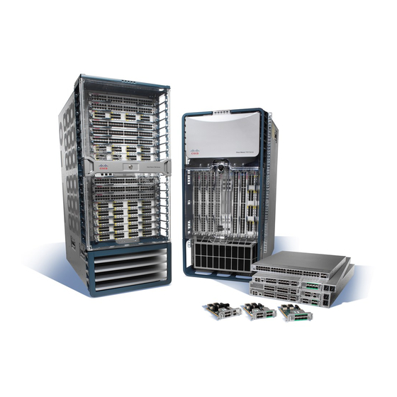
Cisco Nexus 7004 Switch The Cisco Nexus 7004 chassis has four slots that allow for one or two supervisor modules and up to two I/O modules. Additionally, the chassis holds a fan tray, up to four power supplies, and cable management frames. - Page 14 Overview Cisco Nexus 7004 Switch Figure 1: Standard Hardware Features on the Front and Sides of the Cisco Nexus 7004 Chassis Air intake areas for up to four AC or DC power Fan tray supplies (N7K-AC-3KW/N7K-DC-3KW/N7K-HV-3.5KW) or blank filler plates in place of missing power supplies to maintain the designed airflow.
- Page 15 • 8-port 10-Gigabit Ethernet with XL option (N7K-M108X2-12L) The Cisco Nexus F2-Series 48-port 1/10-Gigabit SFP+ module supports all of the standard features of F2 modules and it functions like an F2-series module with Layer 2 and Layer 3 enabled. These modules also support IPv6 DSCP-to-Queue mapping.
-
Page 16: Cisco Nexus 7009 Switch
Cisco Nexus 7009 Switch The Cisco Nexus 7009 chassis has 9 slots that allow for one or two supervisor modules and up to seven I/O modules. Additionally, the chassis also holds up to five fabric modules, one fan tray, up to two power supplies, and cable management frames. - Page 17 Overview Cisco Nexus 7009 Switch Figure 2: Standard Hardware Features on the Front and Sides of the Cisco Nexus 7009 Chassis Air intake area for power supply units Supervisor modules (1 or 2 modules in slots 1 and 2). These modules are of only one of the...
- Page 18 Note Figure 2: Standard Hardware Features on the Front and Sides of the Cisco Nexus 7009 Chassis, on page 5 Figure 3: Standard Hardware Features on the Rear of a Cisco Nexus 7009 Chassis, on page 6 show the Cisco Nexus 7009 chassis as it appears when it is fully configured before including cables for management and network connections.
- Page 19 • 48-port 10/100/1000 I/O modules (N7K-M148GT-11) The Cisco Nexus F2-Series 48-port 1/10-Gigabit SFP+ module supports all of the standard features of F2 modules and it functions like an F2-series module with Layer 2 and Layer 3 enabled. These modules also support IPv6 DSCP-to-Queue mapping.
-
Page 20: Cisco Nexus 7010 System
• 32-port 10-Gigabit Ethernet with XL option and FEX support (N7K-M132XP-12L) • 8-port 10-Gigabit Ethernet with XL option (N7K-M108X2-12L) You must install the Cisco Nexus 7009 chassis in a two- or four-post 19-inch EIA rack that meets the following specifications: •... - Page 21 Overview Cisco Nexus 7010 System Figure 4: Standard Hardware Features on the Front and Sides of the Cisco Nexus 7010 Chassis Door for the cable management area Handles used to reposition the chassis (do not lift the chassis with these handles—use a mechanical...
-
Page 22: 3/4-In. Phillips Screws
Overview Cisco Nexus 7010 System Figure 5: Optional Hardware Features on the Front Side of the Cisco Nexus 7010 Chassis Mid-frame door assembly Air filter Cisco Nexus 7000 Series Hardware Installation and Reference Guide... - Page 23 Note Figure 4: Standard Hardware Features on the Front and Sides of the Cisco Nexus 7010 Chassis, on page 9 Figure 1-6 show the Cisco Nexus 7000 Series chassis as it appears when it is fully configured before including cables for connections to the Internet and the console.
- Page 24 • 48-port 10/100/1000 I/O modules (N7K-M148GT-11) The Cisco Nexus F2-Series 48-port 1/10-Gigabit SFP+ module supports all of the standard features of F2 modules and it functions like an F2-series module with Layer 2 and Layer 3 enabled. These modules also support IPv6 DSCP-to-Queue mapping.
- Page 25 • 32-port 10-Gigabit Ethernet with XL option and FEX support (N7K-M132XP-12L) • 8-port 10-Gigabit Ethernet with XL option (N7K-M108X2-12L) You must install the Cisco Nexus 7010 system chassis in a four-post 19-inch EIA rack that meets the following specifications: • Mounting rails that conform to the English universal hole spacing as specified in ANSI/EIA-310-D-1992.
- Page 26 Overview Cisco Nexus 7010 System Figure 6: One Cisco Nexus 7010 Chassis Installed in a Four-Post Rack Cisco Nexus 7000 Series Hardware Installation and Reference Guide...
-
Page 27: Cisco Nexus 7018 System
Cisco Nexus 7018 System The Cisco Nexus 7018 chassis has 18 slots that allow for two supervisor modules and up to 16 I/O modules. The chassis also holds up to five fabric modules, two fan trays, up to four power supplies, and a cable management system. - Page 28 Overview Cisco Nexus 7018 System Figure 8: Standard Hardware Features on the Front and Sides of the Cisco Nexus 7018 Chassis System status LEDs Air intake for power supply units Rack-mount brackets (2) Air intake for the supervisor modules and I/O...
- Page 29 • Supervisor 1 (N7K-SUP1) • Supervisor 2 (N7K-SUP2) • Supervisor 2 Enhanced (N7K-SUP2E) Figure 9: Cable Management System for the Cisco Nexus 7018 Chassis System status LEDs (these LEDs show the Upper cable management assemblies system status displayed by the chassis LEDs)
- Page 30 Overview Cisco Nexus 7018 System Figure 10: Optional Front Door for the Cisco Nexus 7018 Chassis Front doors Air intake frame for power supply units Cisco Nexus 7000 Series Hardware Installation and Reference Guide...
- Page 31 Overview Cisco Nexus 7018 System Figure 11: Standard Hardware Features on the Back of the Cisco Nexus 7018 Chassis Fabric modules (up to 5) (N7K-C7018-FAB-1 or Fan exhaust for fabric modules N7K-C7018-FAB-2) Cisco Nexus 7000 Series Hardware Installation and Reference Guide...
- Page 32 • 8-port 10-Gigabit Ethernet I/O modules with XL option (N7K-M108X2-12L) The Cisco Nexus F2-Series 48-port 1/10-Gigabit SFP+ module supports all of the standard features of F2 modules and it functions like an F2-series module with Layer 2 and Layer 3 enabled. These modules also support IPv6 DSCP-to-Queue mapping.
- Page 33 You can insert a maximum of ten 24-port 40-Gigabit Ethernet QSFP+ (N7K-M324FQ-25L) I/O modules in the Cisco Nexus 7018 switch. This I/O module uses 96 VQI per slot. The maximum VQI of a Cisco Nexus 7018 switch is 1024 and a total of eleven 24-port 40-Gigabit Ethernet QSFP+ I/0 modules will require 1056 VQI.
- Page 34 Failure to stabilize the rack can cause the rack to tip over. Statement 1048 Figure 12: Cisco Nexus 7018 Chassis Installed in a Four-Post Rack Cisco Nexus 7000 Series Hardware Installation and Reference Guide...
-
Page 35: Preparing The Site
Cisco Nexus 7000 Series system that you are installing. In addition, you must set up a rack or cabinet that can hold the number of chassis that you are installing. To see the general requirements for this system, see Appendix A, “Technical Specifications.”... -
Page 36: Managing The System Hardware
Caution Do not use the handles on the side of the chassis to lift the Cisco Nexus 7009, 7010, or 7018 chassis or a fully loaded Cisco Nexus 7004 chassis (you can use these handles to lift a Cisco Nexus 7004 chassis if you remove the power supplies so that the chassis weighs less than 120 pounds [52 kg]). -
Page 37: Installing A Cisco Nexus 7004 Chassis
Installing a Cisco Nexus 7004 Chassis This chapter describes how to install a new or relocated Cisco Nexus 7004 chassis in a rack or cabinet. For information about installing other Cisco Nexus 7000 Series chassis or power supplies, see the following chapters: •... -
Page 38: Installing A Rack Or Cabinet
Before you install the Cisco Nexus 7004 chassis, you must install a standard two- or four-post, 19-inch EIA data center rack (or a cabinet that contains such a rack) that meets the requirements listed in the Cisco Nexus 7000 Series Site Preparation Guide. To maximize safety, you should do the following for the rack: •... - Page 39 Unpacking and Inspecting a New Switch Before you install a new Cisco Nexus 7004 chassis, you need to unpack and inspect it to be sure that you have all the items that you ordered and verify that the switch was not damaged during shipment. If anything is damaged or missing, contact your customer representative immediately.
-
Page 40: Installing The Chassis
Installing the Chassis Installing the Chassis This section describes how to install the Cisco Nexus 7004 chassis in a rack or cabinet. These installation steps include checking for installation prerequisites, setting up the center-mount brackets if needed, removing the power supplies from the chassis if lifting the chassis manually, and installing the chassis in a rack. When you finish this task, you can connect the chassis to the earth ground, install the cable management frames, install the front door (optional), and reinstall any removed power supplies. -
Page 41: Installing The Center-Mount Brackets
You can either lift the chassis with a mechanical lift and slide it on top of another installed Cisco Nexus 7004 chassis, or you can lighten the chassis and lift it manually into position with a couple of... - Page 42 Lift the chassis to its position on a rack in one of the following ways: • If you use a mechanical lift, position the chassis next to the front of another Cisco Nexus 7004 chassis already installed in the rack, elevate the new chassis to the level of the installed chassis (or no more than 0.25 inches [0.64...
- Page 43 Use five M6 x 19 mm screws (or 12-24 x 3/4 inch screws) to fasten each side of the chassis to the rack. Tighten each of the 10 screws to 40 in. lbs (4.5 N.m) (see Figure 14: Mounting the Cisco Nexus 7004 Chassis on a Rack, on page 31).
-
Page 44: Grounding The Cisco Nexus 7004 Chassis
Operations” section. Grounding the Cisco Nexus 7004 Chassis The Cisco Nexus 7004 switch is fully grounded as soon as you connect the chassis and the power supplies to the earth ground in the following ways: • You connect the chassis to either a grounded and fully bonded rack or to the data center ground. This ground connection is active even when the power supplies are not installed. -
Page 45: Connecting The System Ground
M4 screws, and tighten the screws to 11.5 to 15 in-lb (1.3 to 1.7 N·m). Callout 1 in Figure 16: Grounding Pad and ESD Port Locations on the Cisco Nexus 7004 Chassis, on page 34 shows the location of the grounding pad on the front side of the chassis. -
Page 46: Connecting Your Esd Wrist Strap To The Chassis
Installing a Cisco Nexus 7004 Chassis Connecting Your ESD Wrist Strap to the Chassis Figure 16: Grounding Pad and ESD Port Locations on the Cisco Nexus 7004 Chassis Grounding port Step 5 Prepare the other end of the grounding wire and connect it to an appropriate grounding point in your site to ensure an adequate earth ground for the switch. - Page 47 The top of the frame should be at the same level as the top of the chassis (see Figure 17: Installing the Cable Management Frames on a Cisco Nexus 7004 Chassis, on page 35).
-
Page 48: Installing Usb Storage Media In A Supervisor 2 Or 2E Module
Make sure that the USB drive is fully inserted inside the reader. If it is fully inserted, either format the card (see the Cisco Nexus 7000 Series NX-OS Fundamentals Configuration Guide ) or replace the USB drive with another that is properly formatted for the reader. -
Page 49: Installing A Cisco Nexus 7009 Chassis
Note You must set up a two- or four-post, 19-inch EIA rack or cabinet before you can install the Cisco Nexus 7009 chassis. Make sure that you order the rack or cabinet and have it delivered before installing the chassis. -
Page 50: Installing A Rack Or Cabinet
Additional tools and equipment, such as an electrostatic discharge (ESD) wrist strap, that you will also need to install the Cisco Nexus 7009 chassis, are included in the Cisco Nexus 7009 accessory kit. To see what is included in the accessory kit, see the “Cisco Nexus 7009 Switch Accessory and Optional Kits”... -
Page 51: Unpacking And Inspecting A New Switch
Unpacking and Inspecting a New Switch Before you install a new Cisco Nexus 7009 chassis, you need to unpack and inspect it to be sure that you have all the items that you ordered and verify that the switch was not damaged during shipment. If anything is damaged or missing, contact your customer representative immediately. -
Page 52: Installing The Bottom-Support Rails On The Rack
• Description of the problem and how it affects the installation Installing the Bottom-Support Rails on the Rack You can use the following two types of bottom-support rails to install and hold a Cisco Nexus 7009 chassis to its rack: •... -
Page 53: Prerequisites For Attaching The Bottom-Support Rails
Installing a Cisco Nexus 7009 Chassis Prerequisites for Attaching the Bottom-Support Rails Note When you install a Cisco Nexus 7009 chassis with center-mount brackets, you must always install the chassis onto center-mount bottom-support rails. Caution Do not remove the center-mount brackets when a chassis is installed on them. They are required at all times for holding a center-mount chassis to the rack. -
Page 54: Attaching The Front-Mount Bottom-Support Rails
1. Position one of the two front-mount bottom-support rails at the lowest possible RU on the rack. If you are installing a chassis above another Cisco Nexus 7009 chassis, position the rail 26.25 inches (66.7 cm) (15 RU) above the bottom-support rails for the lower chassis as shown in... - Page 55 Position one of the two front-mount bottom-support rails at the lowest possible RU on the rack. If you are installing a chassis above another Cisco Nexus 7009 chassis, position the rail 26.25 inches (66.7 cm) (15 RU) above the bottom-support...
- Page 56 Installing a Cisco Nexus 7009 Chassis Attaching the Front-Mount Bottom-Support Rails Figure 18: Positioning the Front-Mount Bottom-Support Rails Cisco Nexus 7000 Series Hardware Installation and Reference Guide...
-
Page 57: Attaching The Center-Mount Bottom-Support Rails
Position one of the two center-mount brackets at the lowest possible RU. If you are installing a chassis above another Cisco Nexus 7009 chassis, position the rail 26.25 inches (66.7 cm) (15 RU) above the center-mount bottom-support rails for the lower chassis as shown in... - Page 58 Attaching the Center-Mount Bottom-Support Rails Figure 19: Positioning the Center-Mounted Bottom-Support Rails For the first and heaviest Cisco Nexus 7009 chassis installed in a rack, Allow at least 26.25 inches (66.7 cm) position two center-mount bottom-support rails at the lowest RU on the (15 RU) for each Cisco Nexus 7009 rack.
-
Page 59: Installing The Chassis
Installing the Chassis This section describes how to install the Cisco Nexus 7009 chassis in a rack or cabinet. Depending on your data center requirements, you can choose to mount the front of the chassis to a rack or cabinet (standard method of mounting the chassis), or you can choose to mount the center of the chassis to a rack or cabinet. -
Page 60: Required Tools And Equipment
• If the rack is provided with stabilizing devices, install the stabilizers before mounting or servicing the unit in the rack. Statement 1006 • Cisco Nexus 7009 chassis and its components that are accounted for and undamaged. For more information, see the... -
Page 61: Mounting The Chassis By Its Front Brackets
Center-mount bottom-support rails Center-mount bracket Mounting the Chassis by its Front Brackets To install a Cisco Nexus 7009 chassis by its front brackets to a rack or cabinet, follow these steps: Step 1 Load the chassis onto a mechanical lift as follows: a) Position the mechanical lift next to the shipping pallet that holds the chassis. - Page 62 (use a total of 12 to 14 screws for each of two mounting brackets) as shown in Figure 21: Attaching the Front of the Cisco Nexus 7009 Chassis to the Rack, on page Figure 21: Attaching the Front of the Cisco Nexus 7009 Chassis to the Rack Seven to eight M6 x 19 mm or 10-24 x 3/4 in.
-
Page 63: Mounting The Chassis By Its Center Brackets
Mounting the Chassis by its Center Brackets Mounting the Chassis by its Center Brackets To install a Cisco Nexus 7009 chassis by its optional center bracket to a rack or cabinet, follow these steps: SUMMARY STEPS 1. Follow these steps to replace the front-mount bracket on the chassis with center-mount brackets: 2. - Page 64 Use at least two persons to slide the chassis fully onto the lift so that the side of the chassis touches or is close to the vertical rails on the lift. Make sure that the front and rear of the chassis are unobstructed so you can easily push the chassis into the rack. Cisco Nexus 7000 Series Hardware Installation and Reference Guide...
- Page 65 (See Figure 23: Moving a Cisco Nexus 7009 Chassis onto a Rack (Center-Mount Installation), on page 53.) Figure 23: Moving a Cisco Nexus 7009 Chassis onto a Rack (Center-Mount Installation)
-
Page 66: Grounding The Cisco Nexus 7009 Chassis
Grounding the Cisco Nexus 7009 Chassis If you are using AC power supply units, the Cisco Nexus 7009 system is grounded through the AC power supply cables and one of two grounding connections on the chassis. The AC power supply cables provide a connection to an earth ground whenever you connect the AC power to the system. -
Page 67: Connecting The System Ground
Remove the adhesive label from one of the two system grounding pads, and secure the grounding wire lug to the grounding pad with two M4 screws. Figure 25: Grounding Pad on the Front of the Cisco Nexus 7009 Chassis, on page 56 shows the location of the grounding pads on the front side of the chassis. - Page 68 Installing a Cisco Nexus 7009 Chassis Connecting the System Ground Figure 25: Grounding Pad on the Front of the Cisco Nexus 7009 Chassis Grounding Prepare the other end of the grounding wire and connect it to an appropriate grounding point in your site to ensure an adequate earth ground for the switch.
-
Page 69: Connecting Your Esd Wrist Strap To The Chassis
After you connect the chassis to the data center earth ground, you can ground your ESD wrist strap by plugging it into an ESD port (shown in Figure 26: ESD Grounding Port on the Front of the Cisco Nexus 7009 Chassis, on page 57). -
Page 70: Installing The Cable Management Frames
Attach a cable management frame (part number 800-33786) onto the two hooks that protrude from the lower half of the left front-mount bracket that is attached to the Cisco Nexus 7009 switch chassis, and loosely fasten the frame to the chassis with four flat-head M4x10 screws as shown in . -
Page 71: Installing The Front Door And Air Intake Frame
If you need to install the optional double-hinged door and air intake frame, you must install them after installing the cable management frame on the chassis. To install the front door and air intake frame to the Cisco Nexus 7009 cable management system, follow these steps:... - Page 72 Position the left door stop on the middle of the left cable management frame and fasten it with two M3x10 pan-head screws as shown in Figure 27: Attaching the Left Door Stop, on page 61. Tighten these two screws to 5 to 7 in-lb (0.6 to 0.8 N·m). Cisco Nexus 7000 Series Hardware Installation and Reference Guide...
- Page 73 Place two bushings on the vertical post located half way up the right cable management frame (see Figure 28: Placing Two Bushings on a Cable Management Frame Hinge Post, on page 62). You must open each bushing to fit it around the post. Cisco Nexus 7000 Series Hardware Installation and Reference Guide...
- Page 74 Assemble the two pieces of the right door stop over the bushings and post. Fasten the two pieces together with two M4 flathead screws (see Figure 29: Assembling the Right Door Stop, on page 63). Cisco Nexus 7000 Series Hardware Installation and Reference Guide...
- Page 75 Align the two captive screws on the air intake frame to the two screw holes below the cable management frames on the chassis as shown in Figure 30: Positioning the Air Intake Frame on the Chassis, on page Cisco Nexus 7000 Series Hardware Installation and Reference Guide...
- Page 76 Figure 31: Attaching the Left Side of the Door, on page 65. This action locks the latches around the hinge pins so that you no longer need to hold the door onto the chassis. Cisco Nexus 7000 Series Hardware Installation and Reference Guide...
- Page 77 What to do next Whenever you need to open the door, pull one of the door handles open until it clicks and then swing that side of the door open. Cisco Nexus 7000 Series Hardware Installation and Reference Guide...
-
Page 78: Installing Storage Media In A Supervisor Module
Installing Storage Media in a Supervisor Module Each supervisor module on a Cisco Nexus 7000 Series switch is shipped with a CompactFlash card installed in the LOG FLASH reader (Supervisor 1 modules) or a USB drive installed in the LOG FLASH reader (Supervisor 2 and Supervisor 2E modules). - Page 79 Make sure that the card or USB drive is fully inserted inside the reader. If it is fully inserted, either format the card (see the Cisco Nexus 7000 Series NX-OS Fundamentals Configuration Guide) or replace the storage media with another that is properly formatted for the reader.
- Page 80 Installing a Cisco Nexus 7009 Chassis Installing Storage Media in a Supervisor Module Cisco Nexus 7000 Series Hardware Installation and Reference Guide...
-
Page 81: Preparing To Install The Switch
Installing a Cisco Nexus 7010 Chassis This chapter describes how to install a new or relocated Cisco Nexus 7010 chassis in a rack or cabinet. For information about installing other Cisco Nexus 7000 Series chassis or power supplies, see the following... - Page 82 Before you install the Cisco Nexus 7010 chassis, you must install a standard four-post, 19-inch EIA data center rack (or a cabinet that contains such a rack) that meets the requirements listed in the Cisco Nexus 7000 Series Site Preparation Guide. To maximize safety, you should do the following for the rack: •...
- Page 83 Unpacking and Inspecting a New Switch Before you install a new Cisco Nexus 7010 chassis, you need to unpack and inspect it to be sure that you have all the items that you ordered and verify that the switch was not damaged during shipment. If anything is damaged or missing, contact your customer representative immediately.
-
Page 84: Installing The Bottom-Support Rails On The Rack
Installing the Bottom-Support Rails on the Rack The bottom-support rails hold the Cisco Nexus 7010 chassis on the rack or cabinet. To maximize the stability of the rack, you must attach these rails at the lowest possible rack unit (RU). - Page 85 Position one of the two adjustable bottom-support rails at the lowest possible RU. If you are installing a chassis above another Cisco Nexus 7010 chassis, position the rail 36.75 inches (93.4 cm) (21 RU) above the bottom-support rails for the lower chassis as shown in Figure 33: Positioning the Bottom-Support Rails, on page 74.
- Page 86 Attaching the Bottom-Support Rails Figure 33: Positioning the Bottom-Support Rails For the first and heaviest Cisco Nexus 7010 chassis installed in a rack, Allow at least 36.75 inches (93.4 cm) position two bottom-support rails at the lowest RU on the rack.
-
Page 87: Installing The Chassis
Phillips screws Installing the Chassis This section describes how to install the Cisco Nexus 7010 chassis in a rack or cabinet. These installation steps include transporting the chassis, elevating the chassis to the rack using a mechanical lift, pushing the chassis onto the rack, and then securing the chassis to the rack. - Page 88 For more information, see the Unpacking and Inspecting a New Switch, on page Required Tools and Equipment You need the following tools and equipment to install the Cisco Nexus 7010 chassis: • Mechanical lift capable of lifting at least 550 pounds (250 kg) Caution You must use a mechanical lift whenever lifting a device over 120 pounds (55 kg).
- Page 89 You should also have at least four persons to push the chassis, which can weigh up to 550 pounds (250 kg), onto and off the mechanical lift and rack. Installing the Chassis To install a Cisco Nexus 7010 chassis in a four-post rack or cabinet, follow these steps: SUMMARY STEPS 1. Load the chassis onto a mechanical lift as follows: 2.
- Page 90 Push the lower half of the front side of the chassis so that the back side enters the rack first, and push until the chassis mounting brackets come in contact with the front vertical mounting rails on the rack. Figure 35: Moving a Cisco Nexus 7010 Chassis onto a Rack Push the lower half of the front side of the chassis...
-
Page 91: Grounding The Cisco Nexus 7010 Chassis
Grounding the Cisco Nexus 7010 Chassis The Cisco Nexus 7010 system is grounded through the AC power supply cables and one of two grounding connections on the chassis. The AC power supply cables provide a connection to an earth ground whenever you connect the AC power to the system. - Page 92 • Grounding lug—A two-holed standard barrel lug that supports up to 6 AWG wire. This lug is supplied with the Cisco Nexus 7010 system accessory kit. • Grounding screws—Two M4 x 8 mm (metric) pan-head screws. These screws are shipped with the Cisco Nexus 7010 accessory kit.
- Page 93 Remove the adhesive label from one of the two system grounding pads, and secure the grounding wire lug to the grounding pad with two M4 screws. Figure 38: Grounding Pad on the Front of the Cisco Nexus 7010 Chassis, on page 81 shows the location of the grounding pads on the front side of the chassis.
- Page 94 Installing a Cisco Nexus 7010 Chassis Connecting Your ESD Wrist Strap to the Chassis Figure 39: Grounding Pad on the Rear of the Cisco Nexus 7010 Chassis Grounding Step 5 Prepare the other end of the grounding wire and connect it to an appropriate grounding point in your site to ensure an adequate earth ground for the switch.
- Page 95 Installing a Cisco Nexus 7010 Chassis Connecting Your ESD Wrist Strap to the Chassis Figure 40: ESD Grounding Ports on the Front of the Cisco Nexus 7010 Chassis ESD grounding port Cisco Nexus 7000 Series Hardware Installation and Reference Guide...
-
Page 96: Installing Storage Media In A Supervisor Module
Installing Storage Media in a Supervisor Module Each supervisor module on a Cisco Nexus 7000 Series switch is shipped with a CompactFlash card installed in the LOG FLASH reader (Supervisor 1 modules) or a USB drive installed in the LOG FLASH reader (Supervisor 2 and Supervisor 2E modules). -
Page 97: Installing The Front Doors And Frame Assembly
Make sure that the card or USB drive is fully inserted inside the reader. If it is fully inserted, either format the card (see the Cisco Nexus 7000 Series NX-OS Fundamentals Configuration Guide ) or replace the storage media with another that is properly formatted for the reader. - Page 98 Align the bottom frame assembly so that its four screw holes align to screw holes in the bottom of the chassis, and then screw in four M4 x 6 mm screws to attach the bottom frame to the chassis (see Figure 43: Installing the Bottom Frame, on page 87). Cisco Nexus 7000 Series Hardware Installation and Reference Guide...
- Page 99 For each of the two front doors, match the two alignment pins on the door frame to the alignment holes on the chassis. Position each door frame immediately under the cable management area (see Figure 44: Installing the Front Doors, on page 88). Cisco Nexus 7000 Series Hardware Installation and Reference Guide...
- Page 100 Place door frame on front edge of chassis and immediately under the cable management area. Cable management area. Step 3 Tighten three screws for each door frame (see Figure 45: Attaching the Door Frames to the Chassis, on page 89). Cisco Nexus 7000 Series Hardware Installation and Reference Guide...
- Page 101 For each of two door frames, tighten three captive screws to secure the frame to the chassis. a) Remove the EMI panel by unscrewing its four captive screws until each is free of the chassis (see Figure 46: Removing the EMI Panel, on page 90). Cisco Nexus 7000 Series Hardware Installation and Reference Guide...
- Page 102 EMI panel. Screw in a screw in each of these two screw holes so that the side frame assembly is attached to the EMI panel. Repeat this step for the other side of the EMI panel. See Figure 47: Attaching the Side Frame Assemblies to the EMI Panel, on page Cisco Nexus 7000 Series Hardware Installation and Reference Guide...
- Page 103 Realign the EMI panel to the air intake area on the chassis, screw its four captive screws to the chassis, and tighten the captive screws to 8 in-lb (0.9 N·m). Cisco Nexus 7000 Series Hardware Installation and Reference Guide...
-
Page 104: Installing The Air Filter
Installing a Cisco Nexus 7010 Chassis Installing the Air Filter Installing the Air Filter You can install the optional air filter while the Cisco Nexus 7000 Series system is operational. Note Only the Cisco Nexus 7010 switch includes an optional air filter. -
Page 105: Preparing To Install The Switch
Installing a Cisco Nexus 7018 Chassis This chapter describes how to install a new or relocated Cisco Nexus 7018 chassis in a rack or cabinet. For information about installing other Cisco Nexus 7000 Series chassis or power supplies, see the following... - Page 106 Cisco Nexus 7018 chassis, are included in the Cisco Nexus 7018 accessory kit. Caution When you handle the Cisco Nexus 7018 chassis or its components, you must follow ESD protocol at all times to prevent ESD damage. This protocol includes but is not limited to wearing an ESD wrist strap that you connect to the earth ground.
- Page 107 Unpacking and Inspecting a New Chassis Before you install a new Cisco Nexus 7018 chassis, you need to unpack and inspect it to be sure that you have all the items that you ordered and verify that the switch was not damaged during shipment. If anything is damaged or missing, contact your customer representative immediately.
-
Page 108: Installing The Bottom-Support Rails On The Rack
The power supply units are shipped with the chassis but are boxed separately. • Cisco Nexus 7018 system accessory kit To see a list of what is in the accessory kit, see the Cisco Nexus 7018 System Accessory Kit Contents document, which is included in the kit. - Page 109 98. Adjust the length of the rail so that it stretches from the outer edges of the front and rear vertical mounting rails. You can expand the rail so that its mounting brackets are spaced between 24 to 32 inches (61.0 to 81.3 cm). Cisco Nexus 7000 Series Hardware Installation and Reference Guide...
- Page 110 (using a total of 16 screws for both brackets) as shown in Figure 49: Attaching a Bottom-Support Rail to a Rack, on page 99. Tighten each screw to a maximum of 40 in-lb [4.5 N·m]) of torque. Cisco Nexus 7000 Series Hardware Installation and Reference Guide...
-
Page 111: Installing The Chassis
Before you install the chassis, you must make sure that the following items are available for the installation: • Data center ground is accessible where you are installing the Cisco Nexus 7018 chassis. • Four-post, 19-inch EIA rack or cabinet that includes such a rack. -
Page 112: Required Tools And Equipment
For more information, see the Unpacking and Inspecting a New Chassis, on page Required Tools and Equipment You need the following tools and equipment to install the Cisco Nexus 7000 Series chassis: • Mechanical lift capable of lifting 700 pounds (318 kg) Caution You must use a mechanical lift to lift a switch weighing over 120 pounds (55 kg). -
Page 113: Installing The Chassis
Installing the Chassis To install a Cisco Nexus 7018 chassis in a four-post rack or cabinet, follow these steps: SUMMARY STEPS 1. To lighten the chassis, we recommend that you remove the fan trays from the chassis. The electronics on these modules are well sealed from damage but you must still be careful not to damage their connectors. - Page 114 Use at least two persons to push the chassis half way onto the installed bottom-support rails as shown in Figure 50: Moving a Cisco Nexus 7018 Chassis onto a Rack, on page 103 and a third person to guide the back of the chassis so that it does not get caught on anything as it is pushed into the rack.
- Page 115 Installing a Cisco Nexus 7018 Chassis Installing the Chassis Figure 50: Moving a Cisco Nexus 7018 Chassis onto a Rack Push the sides of the lower half of the front side of the chassis. Rack vertical mounting rails. Chassis mounting brackets.
-
Page 116: Grounding The Cisco Nexus 7018 Chassis
Grounding the Cisco Nexus 7018 Chassis The Cisco Nexus 7018 system is grounded through the AC power supply cables and one of two grounding connections on the chassis. The AC power supply cables provide a connection to an earth ground whenever... -
Page 117: Prerequisites For Grounding The Chassis
Before you can ground the chassis, you must have a connection to the earth ground for the data center building. If you installed the Cisco Nexus 7018 chassis into a bonded rack (see the rack manufacturer’s instructions for more information) that now has a connection to the data center earth ground, you can ground the chassis by connecting its ground ports to the rack. - Page 118 Remove the adhesive label from one of the two system grounding pads, and secure the grounding wire lug to the grounding pad with two M4 screws. Figure 53: Grounding Pad on the Cisco Nexus 7018 Chassis, on page 107 shows the location of the grounding pad on the front side of the chassis.
-
Page 119: Connecting Your Esd Wrist Strap To The Chassis
After you connect the chassis to the earth ground, you can ground your ESD wrist strap by plugging it into the ESD port shown in Figure 54: ESD Grounding Ports on the Front of the Cisco Nexus 7018 Chassis, on page 108. -
Page 120: Installing The Cable Management Frame
Figure 54: ESD Grounding Ports on the Front of the Cisco Nexus 7018 Chassis ESD grounding port Installing the Cable Management Frame After you have fully installed the Cisco Nexus 7018 switch chassis in the rack or cabinet (see the Installing the Chassis, on page 99), you can install the cable management frame on the front of the chassis. - Page 121 Attach a lower cable management assembly (800-31343-01) onto the two hooks that protrude from the lower half of the left rack-mount bracket that is attached to the Cisco Nexus 7018 switch chassis, and loosely fasten the assembly to the chassis with four flat-head M4x10 screws as shown in...
- Page 122 Attach an upper cable management assembly (800-31342-01) onto the two hooks that protrude from the upper half of the left rack-mount bracket that is attached to the Cisco Nexus 7018 switch chassis, and loosely fasten the assembly to the chassis with four flat-head M4x10 screws as shown in...
- Page 123 Repeat Step 3 to attach an upper cable management assembly to the upper right side of the chassis. When completed, the chassis will appear as shown in Figure 57: Cable Management Assemblies Attached to the Rack-Mount Brackets, on page 112. Cisco Nexus 7000 Series Hardware Installation and Reference Guide...
- Page 124 Switch Chassis, on page 113. Push the top hood toward the chassis so that its alignment pins enter the alignment holes and the top hood rests against the chassis. Cisco Nexus 7000 Series Hardware Installation and Reference Guide...
- Page 125 Use four M4x8 pan-head screws to loosely fasten the top hood to the chassis as shown in Figure 59: Fastening the Top Hood to the Chassis and Cable Management Assemblies, on page 114. Cisco Nexus 7000 Series Hardware Installation and Reference Guide...
-
Page 126: Installing The Front Door And Air Intake Frame
Also, make sure that the cable management frame is aligned to the vertical sides of the chassis and that the cable management hood is level when you install those components. To install the front door and air intake frame to the Cisco Nexus 7018 cable management system, follow these steps:... - Page 127 Position the left door stopper (700-27454-01) on the middle of the left cable management frame and fasten it with two M3x10 pan-head screws as shown in Figure 60: Attaching the Left Door Stopper, on page 116. Tighten these two screws to 5 to 7 in-lb (0.6 to 0.8 N·m). Cisco Nexus 7000 Series Hardware Installation and Reference Guide...
- Page 128 M3x10 pan-head screws as shown in Figure 61: Attaching the Right Door Stopper, on page 117. Tighten these two screws to 5 to 7 in-lb (0.6 to 0.8 N·m). Cisco Nexus 7000 Series Hardware Installation and Reference Guide...
- Page 129 Position the hinge bracket (700-28491-01) at the bottom of the cable management frame and the chassis as shown in Figure 62: Positioning the Hinge Bracket to the Cable Management Frame and Chassis, on page 118. Cisco Nexus 7000 Series Hardware Installation and Reference Guide...
- Page 130 Attach the bracket to the chassis with eight loosely fastened M4x8 screws, as shown in Figure 63: Attaching the Hinge Bracket to the Cable Management Frame and Chassis, on page 119. Cisco Nexus 7000 Series Hardware Installation and Reference Guide...
- Page 131 Fasten the four ball-point studs (51-5008-01), each one with a washer (49-0430-01), to the bottom portion of the chassis, one stud by each corner of the air intake area as shown in Figure 64: Fastening Ball-Point Studs to the Air Intake Area, on page 120. Cisco Nexus 7000 Series Hardware Installation and Reference Guide...
- Page 132 Align the air intake frame to the four ball-point studs and press the frame onto the chassis as shown in Figure 65: Positioning the Air Intake Frame on the Chassis, on page 121. The captive screws on the air-intake frame should align with their screw holes in the chassis. Cisco Nexus 7000 Series Hardware Installation and Reference Guide...
- Page 133 The double-hinge door can be installed and opened on either side. The figures in this procedure show how to install the door on the left side first, but you can use the instructions to install it on either side. Cisco Nexus 7000 Series Hardware Installation and Reference Guide...
- Page 134 Figure 67: Attaching the Left Side of the Door, on page 123. This action locks the latches around the hinge pins so that you no longer need to hold the door onto the chassis. Cisco Nexus 7000 Series Hardware Installation and Reference Guide...
- Page 135 Open the door handle on the open side of the door until it clicks. This action opens the latches on the open side of the door. See Figure 68: Attaching the Right Side of the Door, on page 124. Cisco Nexus 7000 Series Hardware Installation and Reference Guide...
- Page 136 Whenever you need to open the door, pull one of the door handles open until it clicks and then swing that side of the door open. Cisco Nexus 7000 Series Hardware Installation and Reference Guide...
-
Page 137: Installing Storage Media In A Supervisor Module
Installing Storage Media in a Supervisor Module Each supervisor module on a Cisco Nexus 7000 Series switch is shipped with a CompactFlash card installed in the LOG FLASH reader (Supervisor 1 modules) or a USB drive installed in the LOG FLASH reader (Supervisor 2 and Supervisor 2E modules). - Page 138 Make sure that the card or USB drive is fully inserted inside the reader. If it is fully inserted, either format the card (see the Cisco Nexus 7000 Series NX-OS Fundamentals Configuration Guide) or replace the storage media with another that is properly formatted for the reader.
-
Page 139: Troubleshooting
Contacting Customer Service, on page 136 Getting Started Start the Cisco Nexus 7000 Series switch by turning on the power at the power supply units to send power to the system fans, supervisor module, fabric modules, and I/O modules. During the startup phase, the STATUS LEDs on the supervisor and I/O modules are amber to indicate that the initialization process is in progress. -
Page 140: Troubleshooting The Fan Trays
3. Make sure that the fan tray is properly seated in the chassis by following these steps: 4. Call Cisco TAC and describe the conditions that you are seeing with the fan tray. See the Contacting Customer Service, on page 136. - Page 141 Verify that the power supply unit is functional by replacing it with another power supply (see the “Replacing an AC Power Supply Unit During Operations” section on page 10-2 ) and plugging its power cords into the same AC source. If Cisco Nexus 7000 Series Hardware Installation and Reference Guide...
-
Page 142: Troubleshooting A Dc Power Supply Unit
Troubleshooting Troubleshooting a DC Power Supply Unit the Input and Output LEDs turn green on the replacement power supply unit, contact Cisco TAC (see the Contacting Customer Service, on page 136) to replace the defective power supply unit. If you cannot determine the problem with the power supply or determine which power supply unit has the problem, contact TAC. - Page 143 When you reinstall a 6-kW power supply, tighten its four captive screws to 8 in-lb (0.90 N·m). d) Turn on the DC power source at the circuit breaker. Cisco Nexus 7000 Series Hardware Installation and Reference Guide...
-
Page 144: Troubleshooting An Hvac/Hvdc Power Supply Unit
If the Output LED is not lit, verify that the power switch is turned on (1). Step 4 Make sure that the power supply unit is properly seated in the power supply bay. Cisco Nexus 7000 Series Hardware Installation and Reference Guide... -
Page 145: Troubleshooting The Supervisor Modules
Step 2 If the STATUS LED (all supervisors modules) and CMP STATUS LED (Supervisor 1 modules only) are unlit, check the module seating and power connections as follows: Cisco Nexus 7000 Series Hardware Installation and Reference Guide... -
Page 146: Troubleshooting The Fabric Modules
• The STATUS LED on the fabric module is red. Note Fabric modules are included with the Cisco Nexus 7009, 7010, and 7018 chassis but not with the Cisco Nexus 7004 chassis. When you start up the switch or install a new fabric module, the STATUS LED on the module is amber while the module initializes. -
Page 147: Troubleshooting The I/O Modules
Loosen the captive screws on the I/O module until they are no longer in the chassis. b) Press the eject buttons on either end of the module. c) Simultaneously rotate out both ejector levers until the module is unseated from the midplane. Cisco Nexus 7000 Series Hardware Installation and Reference Guide... -
Page 148: Contacting Customer Service
• Brief explanation of the steps that you have already taken to isolate and resolve the problem Note If you have CLI access, enter the show sprom all command to display the backplane contents. To contact TAC, go to http://tools.cisco.com/ServiceRequestTool/create/launch.do . Cisco Nexus 7000 Series Hardware Installation and Reference Guide... -
Page 149: Technical Specifications
This appendix describes the technical specifications for the Nexus 7000 system and includes these sections: • Environmental Specifications for the Cisco Nexus 7000 Series Systems, on page 137 • Physical Specifications for the Cisco Nexus 7000 Series Chassis, on page 138 •... -
Page 150: Physical Specifications For The Cisco Nexus 7000 Series Chassis
Rear depth is also the clearance required between the front-mounting rails and the inside of the rear of the rack or cabinet. For front mounted switches, this is the same as the depth of the chassis. For a center-mounted Cisco Nexus 7009 switch, this is 6 inches (15.2 cm) less than the depth of the chassis, which is offset to the front. - Page 151 The weights in these tables do not include the rack or cabinet that holds the chassis or the interface and power cables. For those weights, see the documentation provided by the manufacturers of those components. Table 11: Weights and Quantities for the Cisco Nexus 7004 Switch Components Component...
- Page 152 Technical Specifications Physical Specifications for the Cisco Nexus 7000 Series Chassis Component Weight per Unit Quantity F2 I/O Modules — 1 or 2(can mix I/O module types) 48-port 1- and 10-Gigabit Ethernet I/O module (N7K-F248XP-25 14.0 lb (6.4 kg) and N7K-F248XP-25E) 48-port 1- and 10-GBASE-T I/O module (N7K-F248XT-25E) 14.0 lb (6.4 kg)
- Page 153 — 0 or 1 Front door kit (N7K-C7004-FD-MB) — Air filter (N7K-C7004-AFLT) — 0 or 1 Table 12: Weights and Quantities for the Cisco Nexus 7009 Switch Components Component Weight per Unit Quantity Chassis 100 lb (45.0 kg) Supervisor modules —...
- Page 154 Technical Specifications Physical Specifications for the Cisco Nexus 7000 Series Chassis Component Weight per Unit Quantity F1 I/O Modules — 1 to 7(can mix I/O module types) 32-port 1- and 10-Gigabit Ethernet I/O module (N7K-F132XP-15) 14.0 lb (6.4 kg) F2 I/O Modules —...
- Page 155 0 to 2 Optional Components — — Door and air frame (optional) — 0 or 1 Table 13: Weights and Quantities for the Cisco Nexus 7010 Components Component Weight per Unit Quantity Chassis 200 lb (90.9 kg) Supervisor Modules —...
- Page 156 Technical Specifications Physical Specifications for the Cisco Nexus 7000 Series Chassis Component Weight per Unit Quantity F1 I/O Modules — 1 to 8 (can mix I/O module types) 32-port 1- and 10-Gigabit Ethernet I/O module (N7K-F132XP-15) 14.0 lb (6.4 kg) F2 I/O Modules —...
- Page 157 5 lb (2.3 kg) Optional Components — — Mid-frame doors and frame — 0 or 1 Table 14: Weights and Quantities for the Cisco Nexus 7018 Components Component Weight per Unit Quantity Chassis 187 lb (85.0 kg) Supervisor Modules —...
- Page 158 Technical Specifications Physical Specifications for the Cisco Nexus 7000 Series Chassis Component Weight per Unit Quantity F1 I/O Modules — 1 to 8 (can mix I/O module types) 32-port 1- and 10-Gigabit Ethernet I/O module 14.0 lb (6.4 kg) (N7K-F132XP-15) F2 I/O Modules —...
-
Page 159: Power Specifications For The Cisco Nexus 7000 Series Switches
Power Specifications for the Cisco Nexus 7000 Series Switches The number of power supplies that a Cisco Nexus 7000 Series switch requires depends on the quantities and types of modules that you include in the switch chassis. the type of power supply unit that you are using, and the power redundancy mode that you are using. -
Page 160: Power Requirements For Switch Components
Power Requirements for Switch Components To determine the power requirements of the Cisco Nexus 7000 Series switches, add the power requirements of each of its components. For each component, multiply the number of its modules by its maximum or typical power requirement. - Page 161 — 400 W 48-port 1-/10-Gigabit Ethernet I/O modules with XL 525 W option(N7K-M348XP-25L) 24-port 40-Gigabit Ethernet I/O modules with XL 750 W 600 W option(N7K-M324FQ-25L) Fan Tray 650 W 185 W Cisco Nexus 7000 Series Hardware Installation and Reference Guide...
- Page 162 Technical Specifications Power Requirements for Switch Components Table 16: Power Requirements for the Cisco Nexus 7009 Switch Component Quantity Maximum Typical Supervisor Modules 1 or 2 (same type — — if using 2) Supervisor 1 (N7K-SUP1) 210 W 190 W...
- Page 163 (N7K-M206FQ-23L) 2-port 100-Gigabit Ethernet I/O module with XL option 795 W 690 W (N7K-M202CF-22L) M3 I/O Modules — — 400 W 48-port 1-/10-Gigabit Ethernet I/O modules with XL 525 W option(N7K-M348XP-25L) Cisco Nexus 7000 Series Hardware Installation and Reference Guide...
- Page 164 55 W Fan Trays — — — All fan trays (total) (N7K-C7009-FAN) 650 W 190 W Table 17: Power Requirements for the Cisco Nexus 7010 System Components Component Quantity Maximum Typical Supervisor Modules 1 or 2 (same type — —...
- Page 165 (N7K-M206FQ-23L) 2-port 100-Gigabit Ethernet I/O module with XL option 795 W 690 W (N7K-M202CF-22L) M3 I/O Modules — — 400 W 48-port 1-/10-Gigabit Ethernet I/O modules with XL 525 W option(N7K-M348XP-25L) Cisco Nexus 7000 Series Hardware Installation and Reference Guide...
- Page 166 80 W Fan Trays (N7K-C7010-FAN-F and N7K-C7010-FAN-S) — — — All fan trays (total) 2184 W 300 W Table 18: Power Requirements for the Cisco Nexus 7018 System Components Component Quantity Maximum Typical Supervisor Modules 1 or 2 (same type —...
- Page 167 (N7K-M206FQ-23L) 24-port 10-Gigabit Ethernet I/O module with XL option 795 W 720 W (N7K-M224XP-23L) M3 I/O Modules — — 400 W 48-port 1-/10-Gigabit Ethernet I/O modules with XL 525 W option(N7K-M348XP-25L) Cisco Nexus 7000 Series Hardware Installation and Reference Guide...
-
Page 168: Power Supply Configuration Modes
The amount of power available for use with your Cisco Nexus 7000 Series switch depends on the number of power supplies, input voltage used, and the power mode used. To determine the amount of available power for the power supplies, see the following tables: •... - Page 169 4 power supplies 5800 W 4350 W 2900 W 2900 W The Cisco Nexus 7004 uses up to four 3.0 kW AC power supplies. Table 20: Power Availability for 3.5-kW Inputs (AC) Power Inputs Combined Mode Power Supply Input Source...
- Page 170 4 power supplies 6000 W 4500 W 3000 W 3000 W The Cisco Nexus 7004 uses up to four 3.5 kW inputs. Table 21: Power Availability for 6-kW AC Power Supply Units Combined Mode Power Supply Input Source Full Redundancy...
- Page 171 — — The Cisco Nexus 7018 switch uses up to four 6-kW power supplies, the Cisco Nexus 7010 switch uses up to three 6-kW power supplies, and the Cisco Nexus 7009 uses up to two 6-kW power supplies. Table 22: Power Availability for 7.5-kW AC Power Supplies...
- Page 172 — The Cisco Nexus 7018 switch uses up to four 7.5-kW power supplies, the Cisco Nexus 7010 switch uses up to three 7.5-kW power supplies, and the Cisco Nexus 7009 uses up to two 7.5-kW power supplies. Table 23: Power Availability for 3.0-kW DC Power Supplies...
- Page 173 12,400 W 9,300 W 6,200 W 6,200 W 4 power supplies The Cisco Nexus 7004 uses up to four 3.5 kW DC power supplies. Table 25: Power Availability for 6.0-kW DC Power Supply Units Power Inputs Combined Mode Power Supply...
-
Page 174: Power Supply Cable Specifications
3 power supplies 1 4 power supplies The Cisco Nexus 7018 switch uses up to four 6-kW power supplies, the Cisco Nexus 7010 switch uses up to three 6-kW power supplies, and the Cisco Nexus 7009 uses up to two 6-kW power supplies. - Page 175 Figure 70: CAB-AC-16A-AUS Power Cord and Plugs for the 3-kW and 6-kW AC Power Supply Unit Figure 71: CAB-AC-16A-CH Power Cord and Plugs for the 3-kW and 6-kW AC Power Supply Unit Cisco Nexus 7000 Series Hardware Installation and Reference Guide...
- Page 176 Figure 73: CAB-AC-2500W-INT Power Cord and Plugs for the 3-kW and 6-kW AC Power Supply Unit Figure 74: CAB-AC-2500W-ISRL Power Cord and Plugs for the 3-kW and 6-kW AC Power Supply Unit Cisco Nexus 7000 Series Hardware Installation and Reference Guide...
- Page 177 Figure 76: CAB-AC-C6K-TWLK Power Cord and Plugs for the 3-kW and 6-kW AC Power Supply Unit Figure 77: CAB-7513AC Power Cord and Plugs for the 3-kW and 6-kW AC Power Supply Unit Cisco Nexus 7000 Series Hardware Installation and Reference Guide...
- Page 178 Figure 79: CAB-C19-CBN Power Cord and Plugs for the 3-kW and 6-kW AC Power Supply Unit Figure 80: CAB-ACS-16 Power Cord and Plugs for the 3-kW and 6-kW AC Power Supply Unit Cisco Nexus 7000 Series Hardware Installation and Reference Guide...
- Page 179 200-240 VAC operation North America (locking) CAB-AC-20A-SG-US3 37-1656-01 14' 0" (4.26 m) 20A, 250 VAC 200-240 VAC operation North America 277 VAC CAB-AC-20A-SG-US4 37-1645-01 14' 0" (4.26 m) 20A, 277 VAC operation Cisco Nexus 7000 Series Hardware Installation and Reference Guide...
- Page 180 20A, 300 VAC/500 Terminal source plug North America CAB-HV-25A-SG-US5 37-100903-01 14' 0" (4.26 m) 20A, 300 VAC Figure 82: CAB-AC-16A-SG-AR Power Cord and Connectors for the 3.5-kW HCAC/HVDC Power Supply Unit Cisco Nexus 7000 Series Hardware Installation and Reference Guide...
- Page 181 Figure 83: CAB-AC-16A-SG-AZ Power Cord and Connectors for the 3.5-kW HCAC/HVDC Power Supply Unit Figure 84: CAB-AC-16A-SG-BR Power Cord and Connectors for the 3.5-kW HCAC/HVDC Power Supply Unit Figure 85: CAB-AC-16A-SG-CH Power Cord and Connectors for the 3.5-kW HCAC/HVDC Power Supply Unit Cisco Nexus 7000 Series Hardware Installation and Reference Guide...
- Page 182 Figure 86: CAB-AC-16A-SG-EU Power Cord and Connectors for the 3.5-kW HCAC/HVDC Power Supply Unit Figure 87: CAB-AC-16A-SG-IND Power Cord and Connectors for the 3.5-kW HCAC/HVDC Power Supply Unit Figure 88: CAB-AC-16A-SG-IN Power Cord and Connectors for the 3.5-kW HCAC/HVDC Power Supply Unit Cisco Nexus 7000 Series Hardware Installation and Reference Guide...
- Page 183 Figure 89: CAB-AC-16A-SG-IS Power Cord and Connectors for the 3.5-kW HCAC/HVDC Power Supply Unit Figure 90: CAB-AC-16A-SG-IT Power Cord and Connectors for the 3.5-kW HCAC/HVDC Power Supply Unit Figure 91: CAB-AC-20A-SG-US Power Cord and Connectors for the 3.5-kW HCAC/HVDC Power Supply Unit Cisco Nexus 7000 Series Hardware Installation and Reference Guide...
- Page 184 Figure 92: CAB-AC-20A-SG-US1 Power Cord and Connectors for the 3.5-kW HCAC/HVDC Power Supply Unit Figure 93: CAB-AC-20A-SG-US2 Power Cord and Connectors for the 3.5-kW HCAC/HVDC Power Supply Unit Figure 94: CAB-AC-20A-SG-US4 Power Cord and Connectors for the 3.5-kW HCAC/HVDC Power Supply Unit Cisco Nexus 7000 Series Hardware Installation and Reference Guide...
- Page 185 Figure 95: CAB-AC-20A-SG-C20 Power Cord and Connectors for the 3.5-kW HCAC/HVDC Power Supply Unit Figure 96: CAB-AC-16A-SG-SA Power Cord and Connectors for the 3.5-kW HCAC/HVDC Power Supply Unit Figure 97: CAB-AC-16A-SG-SK Power Cord and Connectors for the 3.5-kW HCAC/HVDC Power Supply Unit Cisco Nexus 7000 Series Hardware Installation and Reference Guide...
- Page 186 Power Supply Cable Specifications Figure 98: CAB-AC-16A-SG-SW Power Cord and Connectors for the 3.5-kW HCAC/HVDC Power Supply Unit Figure 99: CAB-HV-25A-SG-IN1 Power Cord and Connectors for the 3.5-kW HCAC/HVDC Power Supply Unit Cisco Nexus 7000 Series Hardware Installation and Reference Guide...
- Page 187 Figure 100: CAB-HV-25A-SG- IN3 Power Cord and Connectors for the 3.5-kW HVAC/HVDC Power Supply Unit Figure 101: CAB-HV-25A-SG- US1 Power Cord and Connectors for the 3.5-kW HVAC/HVDC Power Supply Unit Figure 102: CAB-HV-25A-SG-US2 Power Cord and Connectors for the 3.5-kW HVAC/HVDC Power Supply Unit Cisco Nexus 7000 Series Hardware Installation and Reference Guide...
- Page 188 Figure 103: CAB-HV-25A-SG-US5 Power Cord and Connectors for the 3.5-kW HVAC/HVDC Power Supply Unit Figure 104: CAB-AC-16A-SG-AZ Power Cord and Plugs for the 3.5-kW HVAC/HVDC Power Supply Unit Figure 105: CAB-AC-16A-SG-BR Power Cord and Plugs for the 3.5-kW HVAC/HVDC Power Supply Unit Cisco Nexus 7000 Series Hardware Installation and Reference Guide...
- Page 189 Figure 106: CAB-AC-16A-SG-CH Power Cord and Plugs for the 3.5-kW HVAC/HVDC Power Supply Unit Figure 107: CAB-AC-16A-SG-EU Power Cord and Plugs for the 3.5-kW HVAC/HVDC Power Supply Unit Figure 108: CAB-AC-16A-SG-IND Power Cord and Plugs for the 3.5-kW HVAC/HVDC Power Supply Unit Cisco Nexus 7000 Series Hardware Installation and Reference Guide...
- Page 190 Figure 109: CAB-AC-16A-SG-IN Power Cord and Plugs for the 3.5-kW HVAC/HVDC Power Supply Unit Figure 110: CAB-AC-16A-SG-IS Power Cord and Plugs for the 3.5-kW HVAC/HVDC Power Supply Unit Figure 111: CAB-AC-16A-SG-IT Power Cord and Plugs for the 3.5-kW HVAC/HVDC Power Supply Unit Cisco Nexus 7000 Series Hardware Installation and Reference Guide...
- Page 191 Figure 112: CAB-AC-20A-SG-US Power Cord and Plugs for the 3.5-kW HVAC/HVDC Power Supply Unit Figure 113: CAB-AC-20A-SG-US1 Power Cord and Plugs for the 3.5-kW HVAC/HVDC Power Supply Unit Figure 114: CAB-AC-20A-SG-US2 Power Cord and Plugs for the 3.5-kW HVAC/HVDC Power Supply Unit Cisco Nexus 7000 Series Hardware Installation and Reference Guide...
- Page 192 Figure 115: CAB-AC-20A-SG-US3 Power Cord and Plugs for the 3.5-kW HVAC/HVDC Power Supply Unit Figure 116: CAB-AC-20A-SG-US4 Power Cord and Plugs for the 3.5-kW HVAC/HVDC Power Supply Unit Figure 117: CAB-AC-20A-SG-C20 Power Cord and Plugs for the 3.5-kW HVAC/HVDC Power Supply Unit Cisco Nexus 7000 Series Hardware Installation and Reference Guide...
- Page 193 Figure 118: CAB-AC-16A-SG-SA Power Cord and Plugs for the 3.5-kW HVAC/HVDC Power Supply Unit Figure 119: CAB-AC-16A-SG-SK Power Cord and Plugs for the 3.5-kW HVAC/HVDC Power Supply Unit Figure 120: CAB-AC-16A-SG-SW Power Cord and Plugs for the 3.5-kW HVAC/HVDC Power Supply Unit Cisco Nexus 7000 Series Hardware Installation and Reference Guide...
- Page 194 Figure 121: CAB-HV-25A-SG-IN2 Power Cord and Plugs for the 3.5-kW HVAC/HVDC Power Supply Unit Figure 122: CAB-HV-25A-SG-IN3 Power Cord and Plugs for the 3.5-kW HVAC/HVDC Power Supply Unit Figure 123: CAB-HV-25A-SG-US2 Power Cord and Plugs for the 3.5-kW HVAC/HVDC Power Supply Unit Cisco Nexus 7000 Series Hardware Installation and Reference Guide...
- Page 195 32 A, 250 VAC Figure 126: IEC 603090 Power Connector for the 7.5-kW AC Power Supply Unit, on page 184 Figure 125: NEMA L6-30 Power Connector for the 7.5-kW AC Power Supply Unit Cisco Nexus 7000 Series Hardware Installation and Reference Guide...
- Page 196 Figure A-85 International, Ring CAB-HV-25A-SG-IN2 37-1640-01 14' 0" (4.26 m) 20 A, 300 VAC/500 Figure A-86 Terminal source plug Note All cables will not be orderable at first customer shipment (FCS). Cisco Nexus 7000 Series Hardware Installation and Reference Guide...
- Page 197 Figure 127: CAB-HV-25A-SG-US1 Power Cord and Plugs for the 3.5-kW HVAC/HVDC Power Supply Figure 128: CAB-HV-25A-SG-US2 Power Cord and Plugs for the 3.5-kW HVAC/HVDC Power Supply Figure 129: CAB-HV-25A-SG-IN1 Power Cord and Plugs for the 3.5-kW HVAC/HVDC Power Supply Unit Cisco Nexus 7000 Series Hardware Installation and Reference Guide...
-
Page 198: Chassis Clearances
Figure 131: Power Connector for the 6.0-kW DC Power Supply Unit Chassis Clearances You must provide each Cisco Nexus 7000 Series switch with adequate clearance for installation, maintenance, cabling, and airflow. Installation clearance includes the cold aisle spacing required in front of the rack or cabinet to allow you to move the switch with a mechanical lift to its rack or cabinet. -
Page 199: Cisco Nexus 7004 Chassis Clearances
Figure 132: Clearances Required for the Cisco Nexus 7004 in a Four-Post Rack with Front-Mount Brackets, on page 188 shows the required clearances for a chassis in a four-post rack with a front-mount installation. - Page 200 Technical Specifications Cisco Nexus 7004 Chassis Clearances Figure 132: Clearances Required for the Cisco Nexus 7004 in a Four-Post Rack with Front-Mount Brackets Chassis Chassis width Cable management frames Right side clearance recommended for cabinet installations: • Use 11 inches (27.9 cm).
- Page 201 No left side clearance required (no airflow on left side) Figure 133: Clearances Required for the Cisco Nexus 7004 in a Two-Post Rack with Front-Mount Brackets Cisco Nexus 7004 chassis No left side clearance required (no airflow on...
- Page 202 Front clearance required for installing the power supplies chassis and replacing the modules Figure 134: Clearances Required for the Cisco Nexus 7004 in a Two-Post Rack with Center-Mount Brackets Cisco Nexus 7004 chassis No left side clearance required (no airflow on...
-
Page 203: Cisco Nexus 7009 Chassis Clearances
Cisco Nexus 7009 Chassis Clearances The Cisco Nexus 7009 chassis has different clearance requirements for installations with four-post racks or cabinets, two-post racks with front-mount brackets, and two-post racks with center-mount brackets. For four-post rack or cabinet installations, the chassis requires the following clearances (see... - Page 204 Technical Specifications Cisco Nexus 7009 Chassis Clearances Figure 135: Clearances Required for a Front-Mounted Cisco Nexus 7009 Chassis in a Four-Post Rack Cisco Nexus 7009 chassis Left side clearance required with an unobstructed opening to the hot aisle to exhaust...
- Page 205 I/O modules chassis and replacing the modules For two-post rack installations with front-mount brackets, the chassis requires the following clearances (see Figure 136: Clearances Required for a Front-Mounted Cisco Nexus 7009 Chassis in a Two-Post Rack, on page 194): •...
- Page 206 Technical Specifications Cisco Nexus 7009 Chassis Clearances Figure 136: Clearances Required for a Front-Mounted Cisco Nexus 7009 Chassis in a Two-Post Rack Cisco Nexus 7009 chassis Side clearance required for open rack installations: • If next to another open rack, use 6 inches (15.2 cm).
- Page 207 I/O modules chassis and replacing the modules For two-post rack installations with center-mount brackets, the chassis requires the following clearances (see Figure 137: Clearances Required for a Center-Mounted Cisco Nexus 7009 Chassis in a Two-Post Rack, on page 196): •...
- Page 208 Technical Specifications Cisco Nexus 7009 Chassis Clearances Figure 137: Clearances Required for a Center-Mounted Cisco Nexus 7009 Chassis in a Two-Post Rack Cisco Nexus 7009 chassis Right side clearance (for rack installations) recommended to input air from the cold aisle: •...
-
Page 209: Cisco Nexus 7010 Chassis Clearances
Front service clearance required for installing and I/O modules the chassis and replacing the modules Cisco Nexus 7010 Chassis Clearances The Cisco Nexus 7010 chassis requires the following clearances (see Figure 138: Clearances Required for the Cisco Nexus 7010 Switch, on page 198): •... - Page 210 Technical Specifications Cisco Nexus 7010 Chassis Clearances Figure 138: Clearances Required for the Cisco Nexus 7010 Switch Cisco Nexus 7010 chassis Chassis width Cable management system No right side clearance required (no airflow on right side) Vertical rack-mount posts Rear service clearance required to replace fan...
-
Page 211: Cisco Nexus 7018 Chassis Clearances
Front service clearance required for installing left side) the chassis and replacing the modules Cisco Nexus 7018 Chassis Clearances The Cisco Nexus 7018 chassis requires the following clearances (see Figure 139: Clearances Required for the Cisco Nexus 7018 Switch, on page 200): •... - Page 212 Technical Specifications Cisco Nexus 7018 Chassis Clearances Figure 139: Clearances Required for the Cisco Nexus 7018 Switch Cisco Nexus 7018 chassis Side clearance recommended for cabinet installations:: • Use 11 inches (27.9 cm) Cable management frames Chassis width Vertical rack-mount post...
-
Page 213: Facility Cooling Requirements
• If next to a wall, use 11 inches (27.9 cm). Facility Cooling Requirements The Cisco Nexus 7000 Series switches dissipate considerable power that generates much heat. The following is the heat dissipation requirement for these switches: • Cisco Nexus 7004 dissipates up to 9737 BTUs per hour •... - Page 214 Technical Specifications Chassis Airflow • The Cisco Nexus 7004 switch uses side-to-back airflow to cool its modules and front-to-back airflow to cool its power supplies as shown in Figure 140: Airflow for the Cisco Nexus 7004 Chassis, on page 202.
- Page 215 Figure 142: Airflow for the Cisco Nexus 7010 Chassis Airflow for cooling the supervisor and I/O Airflow for cooling the power supply units modules Airflow for cooling the fabric modules Cisco Nexus 7000 Series Hardware Installation and Reference Guide...
- Page 216 To allow for the Cisco Nexus 7009 and 7018 switches to take in air from the cold aisle and floor on the right side, you should route cables on the left front side of the switch. If necessary, you can route cables on the upper right front side of the chassis, which leaves the lower right side open to cooling air from the cold aisle in front of the chassis.
-
Page 217: Transceivers And Module Connectors
C H A P T E R Transceivers and Module Connectors This appendix specifies the transceivers and module connectors used with the Cisco Nexus 7000 Series switches. This appendix includes the following sections: • 100-Gigabit CFP Transceivers, on page 205 •... - Page 218 (minimum per lane) nm, 1304.6 nm, and 1309.1 nm CFP-100G-SR10 100GBASE-SR10 –1.0 (maximum per 2.4 (maximum per lane)–9.5 Ten lanes: 840 to 860 nm lane)–7.6 (minimum per (minimum per lane) lane) Cisco Nexus 7000 Series Hardware Installation and Reference Guide...
-
Page 219: 100-Gigabit Cpak Transceivers
1305.63, 1308.09 to 1310.19 CPAK-100G-LR4 100GBASE-LR4 4.5 (maximum per lane)–4.3 4.5 (maximum per Four lanes:1294.53 to 1296.59, (minimum per lane) lane)–10.6 (minimum per 1299.02 to 1301.09, 1303.54 to lane) 1305.63, 1308.09 to 1310.19 Cisco Nexus 7000 Series Hardware Installation and Reference Guide... -
Page 220: 40-Gigabit Cfp Transceivers
209. For the environmental specifications, see Table 40: Environmental and Power Specifications for CFP Transceivers, on page 209. Figure 145: CFP Transceivers Thumb screws Transmit optical bore Dust plug Receive optical bore Cisco Nexus 7000 Series Hardware Installation and Reference Guide... -
Page 221: 40-Gigabit Qsfp+ Transceivers
Receive Specifications, on page 212. For the environmental specifications, see Table 43: Environmental and Power Specifications for CFP Transceivers, on page 213. Figure 146: QSFP+ Transceiver Optical bore Pull tab Cisco Nexus 7000 Series Hardware Installation and Reference Guide... - Page 222 The following 40-Gigabit QSFP+ transceivers are used with the F3-Series 40-Gigabit Ethernet (N7K-M324FQ-25L) I/O modules: • QSFP-H40G-ACUxM • QSFP-H40G-AOCxM • QSFP-4X10G-AC7M • QSFP-4X10G-AC10M • QSFP-4X10G-ACUxM • QSFP-4X10G-AOC1M • QSFP-4X10G-AOC2M • QSFP-4X10G-AOC3M Cisco Nexus 7000 Series Hardware Installation and Reference Guide...
- Page 223 Active optical QSFP+ to — — — 3.3 feet (1 meter)6.6 feet breakout four SFP+ (2 meters)9.8 feet (3 cable meters)16.4 feet (5 assembly meters)23.0 feet (7 meters)32.8 feet (10 meters) Cisco Nexus 7000 Series Hardware Installation and Reference Guide...
- Page 224 (minimum per lane) (minimum per lane) 1291 nm, 1311 nm, and 1331 nm QSFP-4x10G-LR-S 4x10GBASE-LR 0.5 (maximum per lane)–8.2 0.5 (maximum per lane)–14.4 1260 to 1355 (minimum per lane) (minimum per lane) Cisco Nexus 7000 Series Hardware Installation and Reference Guide...
-
Page 225: 10-Gigabit Sfp+ Transceivers And Fabric Extender Transceivers
• M3 Series 48-port 1- and 10-Gigabit Ethernet I/O module with XL option(N7K-M348XP-25L) The 10-Gigabit Fabric Extender Transceiver (FET) is used with only the following I/O modules when connecting them to the Cisco Nexus 2248TP, 2248TP-E, 2232PP, 2232TM, and 2224TP Fabric Extenders (FEXs): •... -
Page 226: 10Base-X Sfp+ Transceivers
• M2 Series 24-port 10-Gigabit Ethernet I/O module with XL option (N7K-M224XP-23L) Starting with Cisco NX-OS Release 8.1(1), the 10-Gigabit Fabric Extender Transceiver (FET) can be used with M3 Series 48-port 1- and 10-Gigabit Ethernet I/O modules with XL option(N7K-M348XP-25L) when connecting them to the Cisco Nexus 2248TP, 2248TP-E, 2232PP, 2232TM, and 2224TP Fabric Extenders (FEXs). - Page 227 XL option (N7K-M224XP-23L) (N7K-M348XP-25L) (N7K-M132XP-12) (N7K-M132XP-12L) CWDM-SFP10G-1xxx DWDM-SFP10G-xx.xx FET-10G SFP-10G-BXD-I SFP-10G-BXU-I SFP-10G-AOC1M SFP-10G-AOC2M SFP-10G-AOC3M SFP-10G-AOC5M SFP-10G-AOC7M SFP-10G-AOC10M SFP-10G-ER SFP-10G-ER-S SFP-10G-LR SFP-10G-LR-S SFP-10G-LRM (SMF) SFP-10G-LRM (MMF) SFP-10G-SR SFP-10G-SR-S SFP-10G-ZR SFP-10G-ZR-S SFP-H10GB-ACU7M SFP-H10GB-ACU10M SFP-H10GB-CU1M Cisco Nexus 7000 Series Hardware Installation and Reference Guide...
- Page 228 SFP-H10GB-CU2-5M SFP-H10GB-CU3M SFP-H10GB-CU5M The FET-10G transceiver is used only for connections with a Cisco Nexus 2248TP, 2248TP-E, 2232PP, 2232TM, and 2224TP Fabric Extender (FEX). Supported from Cisco NX-OS Release 8.1(1). Requires the OneX Converter Module (part number CVR-X2-SFP10G) when this transceiver is used with the 8-port 10-GB I/O module.
- Page 229 Product Number Wavelength (nm) SFP-10G-ER 10GBASE-ER, 1550-nm 4.0 (maximum) –1.0 (maximum) 1530 to 1565 –4.7 (minimum) –15.8 (minimum) SFP-10G-LR 10GBASE-LR, 1310-nm 0.5 (maximum) 0.5 (maximum) 1260 to 1355 –8.2 (minimum) –14.4 (minimum) Cisco Nexus 7000 Series Hardware Installation and Reference Guide...
-
Page 230: 10Base-Dwdm Sfp+ Transceivers
Transceiver Modules Compatibility Matrix . 10-Gigabit X2 Transceivers Note Starting with Cisco NX-OS Release 8.0(1), the 8-port 10-GB Ethernet (N7K-M108X2-12L) I/O modules are not supported. The following 10-Gigabit X2 transceivers are used with the 8-port 10-GB Ethernet (N7K-M108X2-12L) I/O modules:... - Page 231 Figure 148: 10-Gigabit X2 Transceiver (Latching Sleeve Not Extended) Transmit optical bore Transceiver heat sink Receive optical bore Module connector Latching sleeve (retracted) Latch (extended when sleeve is retracted) EMI gasket Cisco Nexus 7000 Series Hardware Installation and Reference Guide...
-
Page 232: 10Gbase-X X2 Transceivers
— 6.2 miles (10 km) X2-10GB-LRM SC duplex 1310 62.5 722 feet (220 meters) 50.0 328 feet (100 meters) 50.0 722 feet (220 meters) G.652 fiber — 984 feet (300 meters) Cisco Nexus 7000 Series Hardware Installation and Reference Guide... - Page 233 IEC 60825-1:2001. Table 51: X2 Transceiver Physical and Environmental Specifications Characteristic Specification Dimensions (H x W x D) 0.53 x 1.41 x 3.58 inches (13.46 x 36 x 91 mm) Cisco Nexus 7000 Series Hardware Installation and Reference Guide...
-
Page 234: 10Gbase-Dwdm X2 Transceivers
10GBASE-DWDM 1558.17 nm X2 DWDM-X2-56.55= 10GBASE-DWDM 1556.55 nm X2 DWDM-X2-55.75= 10GBASE-DWDM 1555.75 nm X2 DWDM-X2-54.94= 10GBASE-DWDM 1554.94 nm X2 DWDM-X2-54.13= 10GBASE-DWDM 1554.13 nm X2 DWDM-X2-52.52= 10GBASE-DWDM 1552.52 nm X2 DWDM-X2-51.72= 10GBASE-DWDM 1551.72 nm X2 Cisco Nexus 7000 Series Hardware Installation and Reference Guide... -
Page 235: 1-Gigabit Sfp Transceivers
• F2 Series 48-port 1- and 10-Gigabit Ethernet I/O modules (N7K-F248XP-25 and N7K-F248XP-25E) • F3 Series 48-port 1- and 10-Gigabit Ethernet I/O modules (N7K-F348XP-25) • M1 Series 48-port 1-Gigabit Ethernet I/O modules (N7K-M148GS-11) Cisco Nexus 7000 Series Hardware Installation and Reference Guide... -
Page 236: 1000Base-Cwdm Sfp Transceiver Cables
(OADM) modules or multiplexer/demultiplexer plug-in modules using SMF cables. CWDM SFP transceivers can transmit and receive optical signals up to 61 miles (100 km) depending on the quality of the fiber-optic cable used. Cisco Nexus 7000 Series Hardware Installation and Reference Guide... -
Page 237: 1000Base-Dwdm Sfp Transceivers
For the specifications that differentiate the 1000BASE-DWDM SFP transceivers, see the Cisco Gigabit Ethernet Transceiver Modules Compatibility Matrix. For specifications and installation information that apply to all CWDM SFP transceivers, see the Cisco SFP and SFP+ Transceiver Module Installation Notes. Cisco Nexus 7000 Series Hardware Installation and Reference Guide... -
Page 238: 1000Base-T And 1000Base-X Sfp Transceivers
Receive optical bore Bail clasp Transmit optical bore Dust plug For the 1000BASE-T and 1000BASE-X transceiver cable specifications, see Table 54: Cable Specifications for 1000BASE-X and 1000BASE-T SFP Transceivers , on page 227. Cisco Nexus 7000 Series Hardware Installation and Reference Guide... - Page 239 The transceivers that support Digital Optical Monitoring have a greater range of temperatures for operations, as shown in Table 55: Environmental Specifications for 1000BASE-X and 1000BASE-T Transceivers , on page 228. Cisco Nexus 7000 Series Hardware Installation and Reference Guide...
-
Page 240: Rj-45 Module Connectors
• 48-port 10/100/1000 Ethernet I/O modules (N7K-M148GT-11 and N7K-M148GT-11L) • 10/100/1000 ports • 48-port 1- and 10-GBASE-T I/O modules (N7K-F248XT-25E) • 1- and 10-GBASE-T ports • Cisco Nexus 2248TP and 2248TP-E Fabric Extenders • 100/1000 downlink ports Cisco Nexus 7000 Series Hardware Installation and Reference Guide... - Page 241 Note If you need to connect a host that operates at up to 10 Mbps to a FEX, you can connect the host to a Cisco Nexus 2248TP-E FEX, which has large port buffers that enable it to work at the slower 10-Mbps speed. If the 10-Mbps host that you are connecting cannot autonegotiate speeds, you must configure the host for 10 Mbps when connecting it to the Cisco Nexus 2248TP-E FEX.
- Page 242 Transceivers and Module Connectors RJ-45 Module Connectors Cisco Nexus 7000 Series Hardware Installation and Reference Guide...
-
Page 243: Accessory Kits Contents
Cisco Nexus 7004 Switch Accessory Kit This section describes the contents of the accessory kit that you can order for the Cisco Nexus 7004 switch. The accessory kit is shipped with each Cisco Nexus 7004 chassis. You use that kit for mounting the chassis on a four-post or two-post rack. - Page 244 GR-1089 Installation and Caution Instructions Note If you do not receive a part listed in this document, contact Cisco Technical Support at this URL: http://www.cisco.com/warp/public/687/Directory/DirTAC.shtml. If you purchased this product through a Cisco reseller, you might receive additional contents in your kit, such as documentation, hardware, and power cables.
- Page 245 • CAB-AC-16A-SG-SW—power cord, 250-VAC 16A, SEV 5934-2/Saf-D-Grid, Switzerland • CAB-HV-25A-SG-US2—power cord, 300-VAC/500-VDC 20A, Ring Terminal/Saf-D-Grid, North America • CAB-HV-25A-SG-US5—power cord, 300-VAC 20A, Saf-D-Grid P-10/Saf-D-Grid P4, North America • CAB-HV-25A-SG-IN2—power cord, 300-VAC/500-VDC 20A, IEC/EU, Ring Terminal/Saf-D-Grid, International Cisco Nexus 7000 Series Hardware Installation and Reference Guide...
-
Page 246: Cisco Nexus 7009 Switch Accessory And Optional Kits
N7K-C7009-CMK). If you need to another bottom support bracket for front-mounting the chassis, order the Cisco Nexus 7009 Bottom Support Kit (part number N7K-C7009-BSK). If you need an additional set of brackets for mounting the front of the chassis to a rack, order the Cisco Nexus 7009 Rack Mount Kit (part number N7K-C7009-RMK). - Page 247 Ground lug kit (includes the following parts): 1 kit • Two-hole lug 1 per kit 2 per kit • M4 x 8-mm Phillips pan-head screws Cable ties, 8.5 inches 1 kit (7 pieces) Cisco Nexus 7000 Series Hardware Installation and Reference Guide...
- Page 248 GR-1089 Installation and Caution Instructions Note If you do not receive a part listed in this document, contact Cisco Technical Support at this URL: http://www.cisco.com/warp/public/687/Directory/DirTAC.shtml. If you purchased this product through a Cisco reseller, you might receive additional contents in your kit, such as documentation, hardware, and power cables.
-
Page 249: Cisco Nexus 7009 Center-Mount Kit
Cisco Nexus 7009 Center-Mount Kit The Cisco Nexus 7009 Center-Mount Kit is not included in the Cisco Nexus 7009 accessory kit, but, if you are centering the Cisco Nexus 7009 chassis on a two-post rack, you must order this kit (N7K-C7009-CMK) when you order the switch. -
Page 250: Cisco Nexus 7009 Rack-Mount Kit
Cisco Nexus 7009 Rack-Mount Kit Cisco Nexus 7009 Rack-Mount Kit The Cisco Nexus 7009 switch ships with the front-mount rack mounting brackets assembled onto the chassis, but you can order the Cisco Nexus 7009 Rack-Mount Kit (order number N7K-C7009-RMK) if you need replacement parts. - Page 251 GR-1089 Installation and Caution Instructions Note If you do not receive a part listed in this document, contact Cisco Technical Support at this URL: http://www.cisco.com/warp/public/687/Directory/DirTAC.shtml. If you purchased this product through a Cisco reseller, you might receive additional contents in your kit, such as documentation, hardware, and power cables.
-
Page 252: Cisco Nexus 7018 Switch Accessory Kits
• CAB-ACS-16—power cord, 16-A, Switzerland • CAB-L520P-C19-US—NEMA L5-20 to IEC-C19 6ft US Cisco Nexus 7018 Switch Accessory Kits Table 62: Cisco Nexus 7018 Switch Accessory Kit Contents , on page 240 lists and illustrates the accessory kit contents for the Cisco Nexus 7018 switch. - Page 253 GR-1089 Installation and Caution Instructions Note If you do not receive a part listed in this document, contact Cisco Technical Support at this URL: http://www.cisco.com/warp/public/687/Directory/DirTAC.shtml. If you purchased this product through a Cisco reseller, you might receive additional contents in your kit, such as documentation, hardware, and power cables.
- Page 254 • CAB-AC-C6K-TWLK—power cord, 250-VAC 16A, twist lock, NEMA L6-20 • CAB-7513AC—power cord, AC 110V North America • CAB-C19-CBN—cabinet jumper power cord, 250-VAC, 16A, C20C • CAB-ACS-16—power cord, 16-A, Switzerland • CAB-L520P-C19-US—NEMA L5-20 to IEC-C19 6ft US Cisco Nexus 7000 Series Hardware Installation and Reference Guide...
-
Page 255: Chassis And Module Leds
C H A P T E R Chassis and Module LEDs This appendix lists the Cisco Nexus 7000 Series system LEDs and describes the conditions they indicate for the chassis and each type of module installed in the chassis. This appendix includes the following sections: •... -
Page 256: Supervisor Module Leds
At least one power supply has failed or the power supply fan has failed. The temperature of the supervisor engine major threshold has been exceeded. The slot has detected a slot ID parity error. Cisco Nexus 7000 Series Hardware Installation and Reference Guide... - Page 257 The management port link has been disabled through the software. Flashing amber The management port link is bad and has been disabled due to a hardware failure. The module does not detect a signal. Cisco Nexus 7000 Series Hardware Installation and Reference Guide...
-
Page 258: I/O Module Leds
I/O module LEDs. Table 65: I/O Module LEDs Status Description Flashing blue The operator has activated this LED to identify this module in the chassis. This module is not being identified. Cisco Nexus 7000 Series Hardware Installation and Reference Guide... -
Page 259: Nam-Nx1 Module Leds
The port is faulty and disabled. The port is not active or the link is not connected. NAM-NX1 Module LEDs Table 66: NAM-NX1 LEDs, on page 248 describes the LEDs on the NAM-NX1. Cisco Nexus 7000 Series Hardware Installation and Reference Guide... -
Page 260: Fabric Module Leds
The port is faulty and disabled. The port is not active or the link is not connected. Fabric Module LEDs Table 67: Fabric Module LEDs , on page 249 describes the fabric module LEDs. Cisco Nexus 7000 Series Hardware Installation and Reference Guide... -
Page 261: Power Supply Leds
The AC, HVAC/HVDC or DC input voltage is outside the valid range. Input 2 (available only on DC Green The DC input voltage is within the valid power supply units) range. Cisco Nexus 7000 Series Hardware Installation and Reference Guide... -
Page 262: Fan Tray Leds
No power is going to the fan tray. The operator has activated this LED to identify this module in the chassis. Flashing blue This module is not being identified. Cisco Nexus 7000 Series Hardware Installation and Reference Guide... -
Page 263: Site Preparation And Maintenance Records
C H A P T E R Site Preparation and Maintenance Records This appendix provides a site planning list to use when preparing your site for the Cisco Nexus 7000 Series switch and includes these sections: • Site Preparation Checklist, on page 251 •... -
Page 264: Contact And Site Information
252) to record contact and site information. Table 71: Contact and Site Information Contact person Contact phone Contact e-mail Building/site name Data center location Floor location Address (line 1) Address (line 2) Cisco Nexus 7000 Series Hardware Installation and Reference Guide... -
Page 265: Chassis And Module Information
254, Table 75: Module Information for the Cisco Nexus 7010 Chassis, on page 254, and Table 76: Module Information for the Cisco Nexus 7018 Chassis , on page 254) to record information about the chassis and modules. Contract Number Chassis serial number Product number>... - Page 266 Site Preparation and Maintenance Records Chassis and Module Information Table 74: Module Information for the Cisco Nexus 7009 Chassis Slot Module Type Module Serial Number Notes Supervisor Supervisor Table 75: Module Information for the Cisco Nexus 7010 Chassis Slot Module Type...
- Page 267 Site Preparation and Maintenance Records Chassis and Module Information Slot Module Type Module Serial Number Notes Supervisor Supervisor Cisco Nexus 7000 Series Hardware Installation and Reference Guide...
- Page 268 Site Preparation and Maintenance Records Chassis and Module Information Cisco Nexus 7000 Series Hardware Installation and Reference Guide...
- Page 269 Cisco Nexus 7018 weight grounding 32, 54, 79, 104 128, 130, 132, 138, 249 6-kW DC power supply unit Cisco Nexus 7004 LEDs Cisco Nexus 7009 128, 130, 132 troubleshooting Cisco Nexus 7000 Series Hardware Installation and Reference Guide IN-1...
- Page 270 Cisco Nexus 7018 door installation 1, 4, 8, 15 mounting on rack equipment Cisco Nexus 7004 installation Cisco Nexus 7009 mounting on a rack Cisco Nexus 7010 overview Cisco Nexus 7018 Cisco Nexus 7000 Series Hardware Installation and Reference Guide IN-2...
- Page 271 33, 55, 80, 105 grounding pad Cisco Nexus 7010 Cisco Nexus 7004 Cisco Nexus 7018 Cisco Nexus 7009 expansion flash reader 36, 66, 84, 125 Cisco Nexus 7010 Cisco Nexus 7018 Cisco Nexus 7000 Series Hardware Installation and Reference Guide IN-3...
- Page 272 26, 39, 71, 95 power supply redundancy Cisco Nexus 7004 modes Cisco Nexus 7009 power supply units 8, 128, 130, 132, 138 Cisco Nexus 7010 location Cisco Nexus 7018 Cisco Nexus 7000 Series Hardware Installation and Reference Guide IN-4...
- Page 273 1, 4, 8, 15, 133, 138, 148, 244 Cisco Nexus 7000 Series Cisco Nexus 7004 1, 138 DC power supply units location fabric modules weight fan trays I/O modules Cisco Nexus 7000 Series Hardware Installation and Reference Guide IN-5...
- Page 274 Cisco Nexus 7009 system fan trays Cisco Nexus 7010 Cisco Nexus 7010 Cisco Nexus 7018 2-port 100-Gigabit Ethernet I/O module with XL supervisor modules 24-port 10-Gigabit Ethernet I/O module with XL Cisco Nexus 7000 Series Hardware Installation and Reference Guide IN-6...