
Related Manuals for Cisco D9887B


Summary of Contents for Cisco D9887B
- Page 1 78- 4043743- 01 R ev A Cisco D9887B HDTV Modular Receiver Software Version 7.7 Installation and Configuration Guide...
- Page 2 Trademark Acknowledgments Cisco and the Cisco logo are trademarks or registered trademarks of Cisco and/or its affiliates in the U.S. and other countries. To view a list of Cisco trademarks, go to this URL: www.cisco.com/go/trademarks. Manufactured under license from Dolby Laboratories. Dolby and the double-D symbol are trademarks of Dolby Laboratories.
- Page 3 Please Read This Entire Guide Veuillez lire entièrement ce guide Bitte das gesamte Handbuch durchlesen Sírvase leer completamente la presente guía Si prega di leggere completamente questa guida Important Please read this entire guide before you install or operate this product. Give particular attention to all safety statements.
-
Page 5: Safety Precautions
Safety Precautions Safety Precautions Read these instructions. Keep these instructions. Heed all warnings. Follow all instructions. Do not use this apparatus near water. Clean only with dry cloth. Do not block any ventilation openings. Install in accordance with the manufacturer's instructions. Do not install near any heat sources such as radiators, heat registers, stoves, or other apparatus (including amplifiers) that produce heat. - Page 6 The product exhibits a distinct change in performance. 19 Replacement Parts: When replacement parts are required, be sure the service technician uses replacement parts specified by Cisco, or parts having the same operating characteristics as the original parts. Unauthorized part substitutions made may result in fire, electric shock or other hazards.
- Page 7 Safety Precautions 20 Safety Check: Upon completion of any service or repairs made to this product, ask the service technician to perform safety checks to determine that the product is in safe operating condition. 21 Outdoor Antenna Grounding: If an outside antenna or cable system is connected to this product, ensure that the antenna or cable system is properly grounded to provide protection against voltage surges and built-up static charges.
- Page 8 Safety Precautions Safety Precautions Protect yourself from electric shock and your system from damage! This product complies with international safety and design standards. Observe all safety procedures that appear throughout this guide, and the safety symbols that are affixed to this product. If circumstances impair the safe operation of this product, stop operation and ...
- Page 9 Safety Precautions Factory service Refer service only to service personnel who are authorized by the factory. Règles de sécurité Protégez-vous des risques d'électrocution et protégez votre système contre les endommagements éventuels. Ce produit respecte les standards internationaux de sécurité et de conception. ...
- Page 10 Safety Precautions Câbles Tirez toujours sur la prise ou le connecteur pour débrancher un câble, Ne tirez jamais directement sur le câble. Ne marchez pas sur les câbles ou les prises et n'y exercez aucune pression. Réparations effectuées à l'usine Ne confiez les travaux de réparations qu'au personnel autorisé...
-
Page 11: Precauciones De Seguridad
Safety Precautions Gehäuse Das Innere des Gerätes ist vor Feuchtigkeit zu schützen. Das Gehäuse ist nicht zu öffnen. Niemals einen Gegenstand durch die Gehäuseöffnungen einführen! Kabel Vor jeglicher Wartung des Gerätes sind alle Kabel zu entfernen. Hierzu grundsätzlich am Stecker oder Verbindungsstück und niemals am Kabel ... -
Page 12: Precauzioni Di Sicurezza
Safety Precautions Conecte este producto únicamente a la fuente de suministro eléctrico indicada en el panel posterior del producto. Si el producto no tiene interruptor para la linea principal, utilice el cordón toma de corriente para este propósito. Cubierta No permita que la humedad penetre en este producto. - Page 13 Safety Precautions Questo prodotto si inserisce in una presa di corrente. La presa di corrente deve essere in prossimità del prodotto, e deve essere facilmente accessibile. Collegare questo prodotto solamente alla fonte di alimentazione indicata sul pannello posteriore di questo prodotto. Se questo prodotto non è...
-
Page 14: Important Notices For Customers In The United Kingdom
Safety Precautions Important Notices for Customers in the United Kingdom Important This notice is applicable only if this apparatus has a three-pin power plug. Warning This apparatus must be earthed. Mains lead colours The following is applicable to Class I apparatus supplied with a flexible cord having cores coloured green-and-yellow, brown, and blue. -
Page 15: Table Of Contents
DC Power Connection (if equipped) ................ 4 Quick Start Guide ........................5 Maintenance..........................6 Chapter 2 Controls and Configuration D9887B Receiver ........................8 Front of Unit ........................ 8 Rear of Unit ........................8 Front Panel Display Layout ....................9 Front Panel Indicators ....................9 Error Logic .......................... - Page 16 Quad Input DVB-S/DVB-S2 with LNB Power Option ........19 CAM Decryption Option ..................19 Dual MPEG over IP Input/UDP Output Option ..........19 Chapter 4 Using the Front Panel to Configure the D9887B HDTV Modular Receiver Input Option – Active Input and Backup Configuration Selection ........ 23 General Information ....................
- Page 17 Digital Audio Settings ....................44 Analog Audio Settings ..................... 44 Output Level ......................45 Dual Video Output (2 SDI, 1 RGBHV/YPbPr/Composite) Option ....... 46 General Information ....................46 Output Control ......................46 Video Settings ......................46 HD Settings ........................ 49 SD Settings .........................
- Page 18 Source Settings ......................86 DVB Mode ........................87 Enabling Advanced DVB-S2 Capabilities.............. 87 LNB Power ......................... 89 22 kHz Tone ....................... 89 Tuning Frequency ..................... 89 Symbol Rate ....................... 91 CA Decryption Option ......................92 General Information ....................92 CAM Decryption Setup .................... 92 BISS Setup ........................
- Page 19 Time .......................... 166 Feature Licensing ......................... 168 To View the Current Licensing ................168 To Enter the License Key ..................168 Chapter 5 Using the Web Client to Configure the D9887B Receiver Login ............................170 Status Indicators ........................171 Configuration ........................172 Input Setup ......................
- Page 20 SMPTE-333M ......................181 Profiles ........................... 182 Saving a Profile......................182 Deleting a Profile..................... 183 Renaming a Profile ....................184 Applying a Saved Profile ..................185 Viewing a Saved Profile ..................185 Downloading a Saved Profile................186 Uploading a Saved Profile ..................187 Web Passwords ........................
- Page 21 Appendix B Specifications D9887B receiver – base unit ....................206 8VSB/QAM Receiver Option ..................... 208 Serial TS Input/Output (DVB-ASI /SMPTE 310M) Option .......... 209 Video Output (1 RGBHV/YPbPr, 1 Composite) Option ..........210 Audio Output (Dolby E, AES Digital, Analog) Option ..........212 Video Output (2 SDI, 1 RGBHV/YPbPr/Composite) Option ........
- Page 22 Declaration of Conformity ....................249 Glossary Index xxii 78-4043743-01 Rev A...
-
Page 23: About This Manual
® Modular Receiver. Note: The manual describes all available options for the D9887B receiver. Your D9887B receiver may only have some of the features described in this manual. Audience The audience includes users (operators) and service personnel who are responsible for the installation, configuration, operation, monitoring, and service of the D9887B receiver. -
Page 25: Chapter 1 Getting Started
Chapter 1 Getting Started Overview This chapter provides installation and a quick setup for your D9887B receiver. In This Chapter Installation ....................2 Quick Start Guide ................... 5 Maintenance .................... 6 78-4043743-01 Rev A... -
Page 26: Installation
70° C, the red “Error” LED will illuminate and a description of the error will appear in the “Error List.” Rack Information The D9887B receiver is intended to be mounted in a standard 19" rack. It occupies 1U of rack space and the connections are all on the rear of the unit. Rack Installation... -
Page 27: Power Connection
D9887B receiver, personnel, or property. AC Power Connection The D9887B receiver is intended for use on either 120V or 240V systems. The power supply will automatically detect the system it is connected to. To hook up the power, use the following steps: Locate the AC power cord included with the D9887B receiver. -
Page 28: Dc Power Connection (If Equipped)
Chapter 1 Getting Started DC Power Connection (if equipped) Using the proper power connections is vital to the safe operation of the D9887B receiver. The D9887B receiver is intended for use in 40-65 VDC systems. The power supply will automatically detect the system it is connected to. When installing the... -
Page 29: Quick Start Guide
Quick Start Guide Quick Start Guide To get the D9887B receiver up and running there is a few things that need to be done. Select the desired input as active. Setup the decoder with the proper PIDs. Setup the desired output(s). -
Page 30: Maintenance
Chapter 1 Getting Started Maintenance The D9887B receiver is virtually a maintenance-free piece of equipment. There are no user serviceable parts on the inside of the unit, however it is recommended that the user cleans the intake filter on the front right side of the unit on a regular basis to ensure an unobstructed cool air intake. -
Page 31: Chapter 2 Controls And Configuration
Chapter 2 Controls and Configuration Overview This chapter describes the controls in the D9887B HDTV Modular Receiver. It describes the most common applications and interfaces of the receiver. In This Chapter D9887B Receiver ..................8 Front Panel Display Layout ..............9 ... -
Page 32: D9887B Receiver
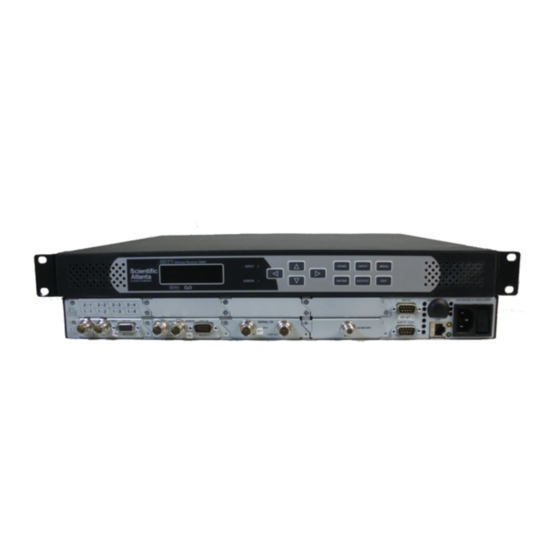
Chapter 2 Controls and Configuration D9887B Receiver Front of Unit Rear of Unit 78-4043743-01 Rev A... -
Page 33: Front Panel Display Layout
When editing, active character or item is highlighted. Front Panel Indicators The D9887B receiver has four internal error parameters: INPUT, DECODER, FAN, and TEMPERATURE. These parameters can be monitored locally or remotely. Locally, the unit’s status can be checked by visually looking at the INPUT LED and the ERROR LED on the front panel, then use the "Error List"... - Page 34 Chapter 2 Controls and Configuration The INPUT LED indicates the presence of a stream at the user-selected input. “Stream present” is represented by a green INPUT LED while “stream NOT present” is represented by a dark INPUT LED. The ERROR LED represents the combined status of the unit’s error indicators. If INPUT, DECODER, TEMP, or FAN status is in the error state, the LED will be red.
-
Page 35: Error Logic
Error Logic Error Logic Input Error Logic The input status is based on the selected input card’s status and the transport error indicator bit in the transport stream being decoded. For example, if the current input is VSB, the input status is based on: VSB receiver lock, RF channel level, and the MER level. -
Page 36: Fan Error Logic
Chapter 2 Controls and Configuration Fan Error Logic If the fan in the unit fails, the fan status will be in the error state. The fan status will be good as long as the fan is spinning at the proper RPM. 78-4043743-01 Rev A... -
Page 37: Snmp Traps
SNMP Traps SNMP Traps The unit contains separate SNMP Traps for Fan Status, Temperature Status, Decoder Status, Input Status, and IP Receive Group. Whenever any item changes state, a trap is sent to the configured host. 78-4043743-01 Rev A... -
Page 38: Input/Output Slot Organization
Chapter 2 Controls and Configuration Input/Output Slot Organization The D9887B receiver’s modular design allows many different input/output configurations. An indexing system is used to identify module slots for configuration and monitoring reference. The bottom row of slots is numbered 1-1 through 1-4 (left to right). -
Page 39: Chapter 3 Option Cards Overview
Option Cards Overview Overview This chapter includes a brief overview of the different option cards that are available for the D9887B receiver. There are descriptions of each card as well as pictures of the various inputs and outputs for each card. -
Page 40: Overview Of The Option Cards
Chapter 3 Option Cards Overview Overview of the Option Cards The following is a list of the option cards available for the D9887B receiver: Option Card Image Option Card Type 8VSB/QAM Receiver Option Serial Transport Stream I/O (DVB-ASI/SMPTE 310M) Option... -
Page 41: Vsb/Qam Receiver Option
2 – 69. With a QAM input, the card will tune to channels 2 – 134 in three cable frequency bands (FCC, IRC, and HRC). The D9887B receiver will show a valid input if the following conditions are met: the receiver equalizer and the FEC are locked. -
Page 42: Video Output (2 Hd/Sd-Sdi, 1 Rgbhv/Ypbpr/Composite) Option
Chapter 3 Option Cards Overview Video Output (2 HD/SD-SDI, 1 RGBHV/YPbPr/Composite) Option A versatile video output card. It provides two user selectable serial digital (SMPTE- 259M, or SMPTE-292M) outputs and one component RGBHV or YPbPr/Composite NTSC & PAL output. Four pairs of audio can be embedded into the serial output on group 1, and 2. -
Page 43: Dual Input Cofdm Receiver Option
CAM Decryption Option This is a factory installed slot that will allow for up to two CAM cards to be installed at a time, providing the D9887B receiver the ability to decrypt Conditional Access transport streams. Dual MPEG over IP Input/UDP Output Option This card is a dual purpose card in that it can receive and/or transmit from the internal TS bus, MPEG over IP. - Page 44 Chapter 3 Option Cards Overview If using FEC the following example applies – Destination port = 5000 "Join Filtered" IGMP V3 Multicast/Unicast – Column FEC = 5002 Filter Mode: Include – Row REC = 5004 IP: X.X.X.X Or – Next available multicast port = Filter Mode: Exclude 5006 IP: X.X.X.X...
-
Page 45: Chapter 4 Using The Front Panel To Configure The D9887B Hdtv Modular Receiver
Overview This chapter describes how to navigate through the configuration menus on the front panel of the D9887B receiver. Note: All instructions in this manual are based on the unit software version 7.3.X. Newer versions of software, when released, may operate slightly different in regards to menus and configuration. - Page 46 Chapter 4 Using the Front Panel to Configure the D9887B HDTV Modular Receiver In This Chapter Input Option – Active Input and Backup Configuration Selection ....................23 8VSB/QAM Receiver Option .............. 26 Serial Transport Stream Input/Output (DVB-ASI/SMPTE 310M) Option ..................
-
Page 47: Input Option - Active Input And Backup Configuration Selection
Input Option – Active Input and Backup Configuration Selection Input Option – Active Input and Backup Configuration Selection General Information The selection of the Active input and configuration of the Backup input are described in this section. Supported Option Cards 8VSB/QAM Receiver option, Serial Transport Stream I/O (DVB-ASI/SMPTE-310M) option, High Bit Rate ASI Input option, Dual Input DVB-S/DVB S2 Receiver option, Dual Input ASM Receiver option, Dual Input COFDM Receiver option, Quad Input... -
Page 48: Configuring Input Backup Settings
Chapter 4 Using the Front Panel to Configure the D9887B HDTV Modular Receiver Press the Enter button again to edit the Active Input. Press the Enter button again to use the Up and Down buttons to change the Active Input selection, then press the Enter button to save the selection. - Page 49 Input Option – Active Input and Backup Configuration Selection Setting the Backup Input Use the Up and Down buttons to move the cursor to the input shown as the Backup Input, then press the Enter button. Use the Up and Down buttons to select the input option to use as the Backup, and then press the Enter button to save the selection.
-
Page 50: 8Vsb/Qam Receiver Option
Chapter 4 Using the Front Panel to Configure the D9887B HDTV Modular Receiver 8VSB/QAM Receiver Option General Information Install Location: Any slot except 1-1 and 2-1. I/O: (1) 75 ohm Female F Connector Supported Formats: 8VSB, QAM-64B, QAM-256B Description: This card provides demodulation of 8 VSB or QAM. For 8 VSB, the card is able to tune to channels 2 - 69 on UHF/VHF and channels 2 - 134 on the cable channel bands of FCC cable, IRC, and HRC. -
Page 51: Channel
8VSB/QAM Receiver Option Channel Use the Up and Down buttons to move the cursor to "Chan," then press the Enter button. Use the Up and Down buttons to tune to the specific RF channel of interest, then press the Enter button to save the selection. Note: The Channel selection is (2 –... -
Page 52: Set Low Signal And Mer Error Levels
Enter button to save the selection. Reset FEC Error Counters The D9887B receiver counts the FEC errors on the input. These counters can be reset to "0" so that monitoring of the counts can beginning from a known reference point. -
Page 53: Serial Transport Stream Input/Output (Dvb-Asi/Smpte 310M) Option
Serial Transport Stream Input/Output (DVB-ASI/SMPTE 310M) Option Serial Transport Stream Input/Output (DVB- ASI/SMPTE 310M) Option General Information Install Location: Any slot except 1-1 and 2-1. I/O: (1) 75Ω Female BNC Input, (1) 75Ω Female BNC Output Supported Formats: DVB-ASI, 310M Description: This card provides either DVB-ASI or 310M input and output. -
Page 54: Input Type
Chapter 4 Using the Front Panel to Configure the D9887B HDTV Modular Receiver Input Type Use the Up and Down buttons to move the cursor to "Type," then press the Enter button. Use the Up and Down buttons to select the appropriate input ("ASI", "310M"), then press the Enter button to save the selection. -
Page 55: Video Output (1 Rgbhv/Ypbpr, 1 Composite) Option
Video Output (1 RGBHV/YPbPr, 1 Composite) Option Video Output (1 RGBHV/YPbPr, 1 Composite) Option General Information Install Location: 1-1 or (2-1 only on Configuration 2 units) I/O: (1) 75Ω Female BNC NTSC/PAL Composite output, (1) 15-pin D-sub Female analog output Supported Formats: NTSC/PAL Composite, YPbPr, RGBHV Description: Analog only, video output card that can output either high definition or standard definition formats. - Page 56 Chapter 4 Using the Front Panel to Configure the D9887B HDTV Modular Receiver Select Format Setting When in "Auto" mode, the unit will automatically pick the format which is closest to the native format of the decoded video in the elementary stream. When in "Manual"...
- Page 57 Video Output (1 RGBHV/YPbPr, 1 Composite) Option Analog Output Format Note: If this setting is set incorrectly when using an RGB monitor, the image will appear green. If this setting is set incorrectly when using a Component monitor, there will be no video on the monitor. Use the Up and Down buttons to move the cursor to "Anlg Out,"...
- Page 58 Auto AFD The Active Format Description (AFD) is a standard set of codes that if sent in the MPEG transport stream, it is interpreted by the D9887B receiver into a certain aspect ratio and active picture characteristics. Use Up the Down and buttons to move the cursor to "Auto AFD," then press the Enter button.
-
Page 59: Composite Vbi Assignment
Video Output (1 RGBHV/YPbPr, 1 Composite) Option Raster Color Use the Up and Down buttons to move the cursor to "Raster Color," then press the Enter button. Use the Up and Down buttons to select the desired raster color ("Black", "White", "Yellow", "Cyan", "Green", "Magenta", "Red", "Blue"), then press the Enter button to save the selection. -
Page 60: Overlay Settings
Chapter 4 Using the Front Panel to Configure the D9887B HDTV Modular Receiver PAL Waveforms To enable PAL items, use the following steps. Use the Up and Down buttons to move the cursor to "TTX," then press the Enter button. -
Page 61: Overlay (Closed Caption)
Video Output (1 RGBHV/YPbPr, 1 Composite) Option Overlay (Closed Caption) Note: This menu changes depending on which overlay is set in "Type of Overlay" above. Use the Up and Down buttons to move the cursor to "Overlay," then press the Enter button. -
Page 62: Overlay (Table)
Chapter 4 Using the Front Panel to Configure the D9887B HDTV Modular Receiver Overlay (Table) Note: This menu changes depending on which overlay is set in "Overlay." Use the Up and Down buttons to move the cursor to "Overlay," then press the Enter button. -
Page 63: Overlay (Service)
Video Output (1 RGBHV/YPbPr, 1 Composite) Option Overlay (Service) Note: This option only displays the Service Info. Overlay (Subtitle) This overlays the DVB Subtitles. The subtitle is selected by choosing the language to display. Only the available languages that are present can be selected. When an input without DVB Subtitles is used, no language can be selected. - Page 64 Chapter 4 Using the Front Panel to Configure the D9887B HDTV Modular Receiver Use the Up and Down buttons to move the cursor to "Genlock Offset," then press the Enter button. Vertical Use the Up and Down buttons to move the cursor to "Vert," then press the Enter button.
-
Page 65: Small Format Display
Down buttons to change the number of degrees (-180 – +180), then press the Enter button to save the selection. Small Format Display To setup the D9887B receiver to output a "Small Format Display," use the following steps: Use the Up and Down buttons to move the cursor to "Small Format Disp," then press the Enter button. - Page 66 Chapter 4 Using the Front Panel to Configure the D9887B HDTV Modular Receiver SFD Location Use the Up and Down button to move the cursor to "SFD Location," and then press the Enter button. Use the Up and Down buttons to select "Top-Lt", "Mid-Lt", "Btm-Lt", Top-Rt", "Mid-Rt", "Btm-Rt", Top-Ctr", "Mid-Ctr", or "Btm-Ctr."...
-
Page 67: Audio Output (Dolby E, Aes Digital, Analog) Option
Audio Output (Dolby E, AES Digital, Analog) Option Audio Output (Dolby E, AES Digital, Analog) Option General Information Install Location: Any slot except 1-1 and 2-1. I/O: (2) 75Ω Female BNC digital outputs, (1) 15-pin D-sub Male analog output Supported Formats: Raw, PCM, Dolby E Description: This card provides two digital audio outputs, and two analog audio pair outputs. -
Page 68: Digital Audio Settings
Chapter 4 Using the Front Panel to Configure the D9887B HDTV Modular Receiver Digital Audio Settings Use the Up and Down buttons to move the cursor to "Out1," then press the Enter button. Use the Up and Down buttons to select the audio decoder and output format desired ("Audio 1 –... -
Page 69: Output Level
Note: The level 7 is approximately 0 dB (when using a -20 dBFS reference level, see Appendix E - D9887B Receiver Audio Explanation (on page 241)) and each number increment is approx. 2.5 dB. Level 9 is approximately +4 dB (when using a -20 dBFS reference level, see Appendix E - D9887B Receiver Audio Explanation (on page 241)). -
Page 70: Dual Video Output (2 Sdi, 1 Rgbhv/Ypbpr/Composite) Option
Chapter 4 Using the Front Panel to Configure the D9887B HDTV Modular Receiver Dual Video Output (2 SDI, 1 RGBHV/YPbPr/Composite) Option General Information Install Location: 1-1 or (2-1 only on Configuration 2 units or Configuration 1 units with dual decoders) I/O: (2) 75Ω... - Page 71 Dual Video Output (2 SDI, 1 RGBHV/YPbPr/Composite) Option Select Format Setting When in "Auto" mode, the unit will automatically pick the format which is closest to the native format of the decoded video in the elementary stream. When in "Manual" mode, the format may be selected from the list of available output formats listed under "Video Format"...
- Page 72 Chapter 4 Using the Front Panel to Configure the D9887B HDTV Modular Receiver SDI Output Setup Follow the steps in this section to set the outputs to SD-SDI and HD-SDI. Use the Up and Down button to move the cursor to "Output A," then press the Enter button.
-
Page 73: Hd Settings
Dual Video Output (2 SDI, 1 RGBHV/YPbPr/Composite) Option Raster Color This setting determines the color of the raster that is output by the decoder when input is lost. Use the Up and Down buttons to move the cursor to "Raster Color," then press the Enter button. - Page 74 Chapter 4 Using the Front Panel to Configure the D9887B HDTV Modular Receiver Video Loss Mode Use the Up and Down buttons to move the cursor to "Video Loss Mode," then press the Enter button. Use the Up and Down buttons to choose between ("Display Raster", "Disable Output"), then press the Enter button to save the selection.
- Page 75 Dual Video Output (2 SDI, 1 RGBHV/YPbPr/Composite) Option Use the Left and Right buttons to select the column to edit and use the Up and Down buttons to change the vertical step (-50 – +50 steps, where the minus direction moves the video to the left), then press the Enter button to save the selection.
-
Page 76: Sd Settings
Chapter 4 Using the Front Panel to Configure the D9887B HDTV Modular Receiver SD Settings Use the Up and Down buttons to move the cursor to "SD Settings," then press the Enter button to display the Status screen for the SD video output settings. - Page 77 Dual Video Output (2 SDI, 1 RGBHV/YPbPr/Composite) Option Video Shift Video Shift provides a horizontal and vertical shift of the video output. Use the Up and Down buttons to move the cursor to "H-shift," then press the Enter button. Use the Left and Right buttons to select the column to edit and use the Up and Down buttons to change the horizontal step (-50 –...
- Page 78 Chapter 4 Using the Front Panel to Configure the D9887B HDTV Modular Receiver Ancillary Data Packets This controls the embedding of the Ancillary Data Packets (ADP) into the VANC of the SDI output. Use the Up and Down buttons to move the cursor to the desired type of Ancillary Data Packet ("EIA-608CC", "EIA-708CC", "TTX S2031M", "Source ID",...
- Page 79 Dual Video Output (2 SDI, 1 RGBHV/YPbPr/Composite) Option PAL Waveforms To enable PAL items, use the following steps. Use the Up and Down buttons to move the cursor to "TTX," then press the Enter button. Use the Up and Down buttons to select "Enabled" or "Disabled," then press the Enter button to save the selection.
-
Page 80: Genlock Offset
Chapter 4 Using the Front Panel to Configure the D9887B HDTV Modular Receiver PAL Waveforms To enable PAL items, use the following steps. Use the Up and Down buttons to move the cursor to "TTX," then press the Enter button. - Page 81 Dual Video Output (2 SDI, 1 RGBHV/YPbPr/Composite) Option Vertical Use the Up and Down buttons to move the cursor to "Vert," then press the Enter button. Use the Left and Right buttons to select the column to edit and use the Up and Down buttons to change the number of lines, then press the Enter button to save the selection.
-
Page 82: Overlay Settings
Chapter 4 Using the Front Panel to Configure the D9887B HDTV Modular Receiver Overlay Settings Overlays provide an easy way to help troubleshoot problems, monitor stream characteristics, or decode closed captioning. CAUTION: All overlays will appear on the downstream video. -
Page 83: Overlay (Table)
Dual Video Output (2 SDI, 1 RGBHV/YPbPr/Composite) Option NTSC Closed Captions Note: This option will only be available if the TYPE of overlay is set to "Closed Caption" and the "Overlay" is set to "NTSC." Use the Up and Down buttons to move the cursor to "NTSC Srvc," then press the Enter button. -
Page 84: Overlay (Service)
Chapter 4 Using the Front Panel to Configure the D9887B HDTV Modular Receiver Screen Interaction This mode allows the user to page through the on-screen PSI/ATSC tables. Note: This option is only available if the type of overlay is set to "Table."... -
Page 85: Overlay (Subtitle)
Enter button to save the selection. Small Format Display To setup the D9887B receiver to output a "Small Format Display," use the following steps: Use the Up and Down buttons to move the cursor to "Small Format Disp," then press the Enter button. - Page 86 Chapter 4 Using the Front Panel to Configure the D9887B HDTV Modular Receiver Press the Enter button to save the settings. 720 x 480i 16x9 29.97 1920 x 1080i 16x9 30.00 720 x 480i 29.97 1920 x 1080PsF 16x9 23.98 720 x 576i 25.00...
-
Page 87: Dual Input Dvb-S/Dvb-S2 Receiver Option
Dual Input DVB-S/DVB-S2 Receiver Option Dual Input DVB-S/DVB-S2 Receiver Option General Information Install Location: Any slot except 1-1 or 2-1. I/O: (2) 75Ω Female F Connectors Supported Formats: DVB-S/DVB-S2 Description: This card will input a satellite L-band (950 MHz – 2150 MHz) signal for demodulation of KU-band or C-band DVB-S QPSK signals or DVB-S2 QPSK/8PSK signals. -
Page 88: Source
Chapter 4 Using the Front Panel to Configure the D9887B HDTV Modular Receiver Use the Up and Down buttons to move the cursor to the "DVB-S/S2" card of the specific slot (e.g. 2-2). Notice the location diagram in the upper right corner of the screen changes as the cursor moves by each card. -
Page 89: Input B
Dual Input DVB-S/DVB-S2 Receiver Option Frequency A The DVB-S/S2 card tunes by the L-band frequency rather than the transponder frequency or local oscillator value. The L-band frequency is the difference between the downlink transponder frequency and the LNB local oscillator frequency. Use the Up and Down buttons to move the cursor to "Freq,"... - Page 90 Chapter 4 Using the Front Panel to Configure the D9887B HDTV Modular Receiver Frequency B The DVB-S/S2 card tunes by the L-band frequency rather than the transponder frequency or local oscillator value. The L-band frequency is the difference between the downlink transponder frequency and the LNB local oscillator frequency.
-
Page 91: Dual Input Asm Receiver Option
Dual Input ASM Receiver Option Dual Input ASM Receiver Option General Information Install Location: Any slot except 1-1 or 2-1. I/O: (2) 75Ω Female F Connectors Supported Formats: DVB-S/DVB-S2 Description: This card will input a satellite L-band (950 MHz – 2150 MHz) signal for demodulation of KU-band, C-band, or X-band DVB-QPSK, 8PSK, or Adv-QPSK signals. -
Page 92: Source
Chapter 4 Using the Front Panel to Configure the D9887B HDTV Modular Receiver Use the Up and Down buttons to move the cursor to the "AdvPSK" card of the specific slot (e.g. 2-2). Notice the location diagram in the upper right corner of the screen changes as the cursor moves by each card. - Page 93 The ASM card offers an offset for the Local Oscillator frequency. This means that the D9887B receiver will calculate the actual frequency in which the card tunes; saving the user time and possible miscalculation errors. Follow the steps below to change the offset or set to zero for manual calculation.
-
Page 94: Input B
Chapter 4 Using the Front Panel to Configure the D9887B HDTV Modular Receiver Symbol Rate A Use the Up and Down buttons to move the cursor to "SymRt," then press the Enter button. Use the Left and Right buttons to select the column to edit, and use the Up and Down buttons to change the symbol rate (0.256 –... - Page 95 The ASM card offers an offset for the Local Oscillator frequency. This means that the D9887B receiver will calculate the actual frequency in which the card tunes; saving the user time and possible miscalculation errors. Follow the steps below to change the offset or set to zero for manual calculation.
-
Page 96: Video Output (2 Hd/Sd-Sdi, 1 Rgbhv/Ypbpr/Comp) Option
Chapter 4 Using the Front Panel to Configure the D9887B HDTV Modular Receiver Video Output (2 HD/SD-SDI, 1 RGBHV/YPbPr/Comp) Option General Information Install Location: This card can only be installed in location 2-1. I/O: (2) 75Ω HD-SDI Female BNC outputs, (1) 15-pin D-sub Female analog output... -
Page 97: Video Output (2 Hd/Sd-Sdi, 1 Rgbhv/Ypbpr/Comp) Option
Video Output (2 HD/SD-SDI, 1 RGBHV/YPbPr/Comp) Option Select Format Setting When in "Auto" mode, the unit will automatically pick the format which is closest to the native format of the decoded video in the elementary stream. When in "Manual" mode, the format may be selected from the list of available output formats listed under "Video Format"... - Page 98 Chapter 4 Using the Front Panel to Configure the D9887B HDTV Modular Receiver Use the Up and Down button to move the cursor to "Disp Mode," then press the Enter button. Use the Up and Down buttons to select either "Letterbox" or "Cropped," then press the Enter button to save the selection.
- Page 99 Video Output (2 HD/SD-SDI, 1 RGBHV/YPbPr/Comp) Option Note: When set to "SD," the NTSC formatted output will be used when the output video frame rate is 29.95 or 59.94. The PAL formatted output will be used when the frame rate is 25 or 50. Other frame rates will not produce an SD SDI output.
-
Page 100: Hd Sdi Vanc Embedding
Chapter 4 Using the Front Panel to Configure the D9887B HDTV Modular Receiver Display Mode Use the Up and Down buttons to move the cursor to "Disp Mode," then press the Enter button. Use the Up and Down buttons to select the desired output size ("Letterbox", "Cropped"), then press the Enter button to save the selection. -
Page 101: Sd Sdi Vanc Embedding
Video Output (2 HD/SD-SDI, 1 RGBHV/YPbPr/Comp) Option Press the Enter button once more to display the Edit menu. Use the Up and Down buttons to move the cursor to "EIA-608CC," then press the Enter button. Use the Up and Down buttons to choose "Enabled" or "Disabled," then press the Enter button to save the selection. -
Page 102: Composite Vbi Assignment
Chapter 4 Using the Front Panel to Configure the D9887B HDTV Modular Receiver Use the Up and Down buttons to move the cursor to "EIA-608CC," then press the Enter button. Use the Up and Down buttons to choose "Enabled" or "Disabled," then press the Enter button to save the selection. -
Page 103: Hd/Sd Genlock Offset
Video Output (2 HD/SD-SDI, 1 RGBHV/YPbPr/Comp) Option Then use the Up and Down buttons to toggle between "Enabled" and "Disabled," then press the Enter button to save changes. HD/SD Genlock Offset The Video Output (2 HD/SD-SDI, 1 RGBHV/YPvPr/Comp) option card can be Genlocked to a standard "black and burst"... -
Page 104: Horizontal
Chapter 4 Using the Front Panel to Configure the D9887B HDTV Modular Receiver Horizontal Use the Up and Down buttons to move the cursor to "Horiz," then press the Enter button. Use the Left and Right buttons to select the column to edit and use the Up and Down buttons to change the number of pixels, then press the Enter button to save the selection. -
Page 105: Dual Input Cofdm Receiver Option
I/O: (2) 75Ω Female F Connectors Supported Formats: COFDM Description: This card will allow the D9887B receiver to receive a COFDM signal for use in electronic news gathering (U.S.) or any COFDM Terrestrial Broadcast (DVB-T, European) applications. Only one input may be selected at a time. -
Page 106: Source
Chapter 4 Using the Front Panel to Configure the D9887B HDTV Modular Receiver Source This option will select which input, on the back of the card, will be active. Use the Up and Down buttons to move the cursor to "Source," then press the Enter button. -
Page 107: Input B
Dual Input COFDM Receiver Option Spectrum A Use the Up and Down buttons to move the cursor to "Spectrum," then press the Enter button. Use the Up and Down buttons to change the spectrum ("Normal", "Inverted"), then press the Enter button to save the selection. Input B These settings correspond to the input on "Source B."... - Page 108 Chapter 4 Using the Front Panel to Configure the D9887B HDTV Modular Receiver Spectrum B Use the Up and Down buttons to move the cursor to "Spectrum," then press the Enter button. Use the Up and Down buttons to change the spectrum ("Normal", "Inverted"), then press the Enter button to save the selection.
-
Page 109: Quad Input Dvb-S/Dvb-S2 Receiver With Lnb Power Option
Quad Input DVB-S/DVB-S2 Receiver with LNB Power Option Quad Input DVB-S/DVB-S2 Receiver with LNB Power Option General Information Install Location: Any slot except 1-1 or 2-1. I/O: (2) 75Ω Female F Connectors Supported Formats: DVB-S/DVB-S2 Description: This input provides a satellite L-band (950 MHz – 2150 MHz) signal for demodulation of KU-band or C-band DVB-S QPSK signals or DVB-S2 QPSK/8PSK signals. -
Page 110: Source
Chapter 4 Using the Front Panel to Configure the D9887B HDTV Modular Receiver Use the Up and Down buttons to move the cursor to the "DVB-S/S2" card of the specific slot (e.g. 1-4). Notice the location diagram in the upper right corner of the screen changes as the cursor moves by each card. -
Page 111: Dvb Mode
License is noted in the License "Feature List." The license enables the "Advanced Satellite Features" capabilities for all Quad Input DVB-S/DVB-S2 Receiver with LNB option cards in the D9887B receiver. When licensed, the "Multistream" settings will be available and the Quad Input DVB-S/DVB-S2 Receiver with LNB option card will be able to receive multistream transport streams, VCM, 16APSK and 32APSK modulation. - Page 112 Chapter 4 Using the Front Panel to Configure the D9887B HDTV Modular Receiver Note: The setting of the "ISI" is only available when the "Multistream Mode" is set to "On." Use the Up and Down buttons to move the cursor to "ISI Mode," then press the Enter button.
-
Page 113: Lnb Power
Quad Input DVB-S/DVB-S2 Receiver with LNB Power Option LNB Power LNB power is configurable separately for each Source input, but is only supplied to the active source. Use the Up and Down buttons to move the cursor to "LNB Power," then press the Enter button. - Page 114 Chapter 4 Using the Front Panel to Configure the D9887B HDTV Modular Receiver Local Oscillator Offset The Local Oscillator Offset provides preset values that can be selected using the List mode. Any valid Local Oscillator Offset value can be entered using the Manual mode.
-
Page 115: Symbol Rate
Quad Input DVB-S/DVB-S2 Receiver with LNB Power Option Satellite Frequency Use the Up and Down buttons to move the cursor to "Sat Freq," then press the Enter button. Use the Left and Right buttons to select the column to edit and use the Up and Down buttons to change the frequency (950 MHz –... -
Page 116: Ca Decryption Option
I/O: Two external slots in the front of the unit. The transport stream is input and output through the various other option cards. Description: The D9887B receiver can be configured with this option to be able to decrypt a Conditional Access transport stream. In Config 1, the dual CAM functionality can be used to decrypt multiple services to send out ASI, essentially looping the stream through the D9887B receiver for decryption. - Page 117 In the "Use Decoded PIDs" operation mode, the CAM will decrypt the audio and video programs that are decoded by the D9887B receiver. The Service Selection tuning determines the program that is sent to the CAM for decrypting before the decoding takes place.
- Page 118 Chapter 4 Using the Front Panel to Configure the D9887B HDTV Modular Receiver Use Selected PIDs The "Use Selected PIDs" operation mode allows the selection of individual video and audio PIDs to send to the CAM for decryption. There is no restriction on which PIDs can be selected (audio and video PIDs need not be in the same program).
-
Page 119: Biss Setup
"*"’ed Service. BISS Setup To setup the D9887B receiver to be able to decrypt a BISS encrypted transport stream use the following steps: Press the Home button to bring the display back to the RDS status screen. - Page 120 Mode BISS 1 Once the D9887B receiver has been set to use Mode 1, use the following steps to enter the session word: Use the Up and Down buttons to move the cursor to "Session Word," then press the Enter button.
- Page 121 CA Decryption Option Mode BISS E Once the D9887B receiver has been set to use Mode E, use the steps below to enter the "Encrypted Session Word" and "Injected ID." Use the Up and Down buttons to move the cursor to "Encrypt Session Word,"...
-
Page 122: Dual Mpeg Over Ip Input/ Udp Output Option
This menu is used to setup the IP address, Subnet Mask, and Gateway for the MPEG/IP card. These settings need to be set to proper values for the network that the D9887B receiver is being used on. These values can usually be obtained from the local network administrator. - Page 123 Dual MPEG over IP Input/ UDP Output Option IP Address/Subnet Mask/Gateway Use the Up and Down buttons to move the cursor to "IP Address," then press the Enter button. Use the Left and Right buttons to select the column to edit and use the Up and Down buttons to change the IP, then press the Enter button to save the selection.
-
Page 124: To Edit The Option Card Input Settings
Chapter 4 Using the Front Panel to Configure the D9887B HDTV Modular Receiver To Edit the Option Card Input Settings To edit this input card, use the following steps: Press the Input button. Note: For Configuration 2 units, select RDS1 or RDS2, then press Enter. - Page 125 Dual MPEG over IP Input/ UDP Output Option Note: Using "Auto" will enable the backup functionality. Note: When the backup functionality is being used, the user can choose which Receive Group is being used as follows: setting the "Pri Group" to the desired group or by setting the "Active Group"...
-
Page 126: Receive 1
Chapter 4 Using the Front Panel to Configure the D9887B HDTV Modular Receiver Setting when to Restore to the Primary Note: This is not changeable when using "TrigDecErr" ("Pri Rest" is set to "Never" in this case). Use the Up and Down buttons to move the cursor to "Pri Rest," then press the Enter button. - Page 127 Dual MPEG over IP Input/ UDP Output Option Use the Up and Down buttons to move the cursor to "Receive," then press the Enter button. Use the Up and Down buttons to "Enable" or "Disable" Receive 1, then press the Enter button to save the selection.
- Page 128 Chapter 4 Using the Front Panel to Configure the D9887B HDTV Modular Receiver Use the Left and Right buttons to select the column to edit and use the Up and Down buttons to change the port (0 – 65536), then press the Enter button to save the selection.
- Page 129 Dual MPEG over IP Input/ UDP Output Option Buffer Use the Up and Down buttons to move the cursor to "Buffer," then press the Enter button. Use the Left and Right buttons to select the column to edit and use the Up and Down buttons to change the Buffer (from 3999 kb to 100 kb), then press the Enter button to save the selection.
- Page 130 Chapter 4 Using the Front Panel to Configure the D9887B HDTV Modular Receiver Note: Existing IP addresses are shown before the "Add IP" option. Use the Left and Right buttons to select the column to edit and use the Up and Down buttons to change the IP address, then press the Enter button to save the selection.
-
Page 131: Receive 2
Dual MPEG over IP Input/ UDP Output Option Receive 2 This section allows the user to setup the receive function of the second receive group. Use the Up and Down buttons to move the cursor to "Receive 2," then press the Enter button. - Page 132 Chapter 4 Using the Front Panel to Configure the D9887B HDTV Modular Receiver Multicast: 224.0.0.0 – 239.255.255.255 Suggested Multicast Range: 239.192.X.X Destination Port Use the Up and Down buttons to move the cursor to "Dest Port," then press the Enter button.
- Page 133 Dual MPEG over IP Input/ UDP Output Option Buffer Use the Up and Down buttons to move the cursor to "Buffer," then press the Enter button. Use the Left and Right buttons to select the column to edit and use the Up and Down buttons to change the Buffer (from 3999 kb to 100 kb), then press the Enter button to save the selection.
-
Page 134: Reset Counters
Chapter 4 Using the Front Panel to Configure the D9887B HDTV Modular Receiver Use the Left and Right buttons to select the column to edit and use the Up and Down buttons to change the IP address, then press the Enter button to save the selection. -
Page 135: Output Control
Dual MPEG over IP Input/ UDP Output Option Use the Up and Down buttons to move the cursor to "Reset Counters," then press the Enter button. Press the Enter button again to reset the counters. Output Control To configure this card as an output, use the following steps: Press the Output button. - Page 136 Chapter 4 Using the Front Panel to Configure the D9887B HDTV Modular Receiver Use the Up and Down buttons to move the cursor to "Phys Conn," then press the Enter button. Choose the physical connector using the Up and Down buttons ("Port 1" or "Port 2"), then press the Enter button.
- Page 137 Dual MPEG over IP Input/ UDP Output Option Packets Per Frame Use the Up and Down buttons to move the cursor to "Packets/Ip," then press the Enter button. Use the Left and Right buttons to select the column to edit and use the Up and Down buttons to change the number of packets per frame (1 –7), then press the Enter button to save the selection.
- Page 138 Chapter 4 Using the Front Panel to Configure the D9887B HDTV Modular Receiver Use the Up and Down buttons to move the cursor to "Phys Conn," then press the Enter button. Choose the physical connector using the Up and Down buttons ("Port 1" or "Port 2"), then press the Enter button.
- Page 139 Dual MPEG over IP Input/ UDP Output Option Packets Per Frame Use the Up and Down buttons to move the cursor to "Packets/Ip," then press the Enter button. Use the Left and Right buttons to select the column to edit and use the Up and Down buttons to change the number of packets per frame (1 –7), then press the Enter button to save the selection.
-
Page 140: Mpeg-2/Mpeg-4 4:2:0 Decoder (1 Video, 2 Audio) Option
Description: The D9887B receiver can be configured as a Single RDS or as a Dual RDS. As a Single RDS, the D9887B receiver has only one MPEG Decoder. As a Dual RDS, the D9887B receiver has two MPEG Decoders. The D9887B receiver can be configured, when ordering, to act as two separate RDSs or as one RDS with two decoders to enable four audio processors. -
Page 141: Tune Mode
PID Select determines how the PID will be entered during the following steps. The "Manual" mode allows any PID to be entered. In "List" mode, the D9887B receiver will only allow the PIDs to be entered that are in the PMT. In the following steps, only the Up and Down buttons are needed to change the PID if this option is set to "List."... - Page 142 Chapter 4 Using the Front Panel to Configure the D9887B HDTV Modular Receiver Video Use the Up and Down buttons to move the cursor to "Video PID," then press the Enter button. Use the Left and Right buttons to select the column to edit and use the Up and Down buttons to set the PID, then press the Enter button to save the selection.
-
Page 143: Priority Mode
MPEG-2/MPEG-4 4:2:0 Decoder (1 Video, 2 Audio) Option Audio 4 PID Note: This menu is only available if the unit is equipped with a second decoder in Configuration 1. Use the Up and Down buttons to move the cursor to "Aud 4 PID," then press the Enter button. - Page 144 Chapter 4 Using the Front Panel to Configure the D9887B HDTV Modular Receiver Service Use the Up and Down buttons to move the cursor to "Service," then press the Enter button. Use the Left and Right buttons to select the column to edit and use the Up and Down buttons to select the program, then press the Enter button to save the selection.
-
Page 145: No Psi Mode
MPEG-2/MPEG-4 4:2:0 Decoder (1 Video, 2 Audio) Option Use the Up and Down buttons to set the desired audio index (0 – 65535), then press the Enter button to save the selection. Audio 4 Index Note: This menu is only available if the unit is equipped with a second decoder in Configuration 1. - Page 146 Chapter 4 Using the Front Panel to Configure the D9887B HDTV Modular Receiver Use the Left and Right buttons to select the column to edit, then use the Up and Down buttons to set the desired Video PID in the stream, then press the Enter button to save the PID.
- Page 147 MPEG-2/MPEG-4 4:2:0 Decoder (1 Video, 2 Audio) Option Audio 2 PID Use the Up and Down buttons to move the cursor to "Aud 2 PID," then press the Enter button. Use the Left and Right buttons to select the column to edit, then use the Up and Down buttons to select the desired Audio PID in the stream, then press the Enter button to save the PID.
- Page 148 Chapter 4 Using the Front Panel to Configure the D9887B HDTV Modular Receiver Audio 3 Type Note: This menu is only available if the unit is equipped with a second decoder in Configuration 1. Use the Up and Down buttons to move the cursor to "Audio1 Typ," then press the Enter button.
-
Page 149: Auto Mode
MPEG-2/MPEG-4 4:2:0 Decoder (1 Video, 2 Audio) Option Dolby E 1 Note: This option is only available if there is an Audio Output (Dolby E, AES Digital, Analog) option audio output card installed. Use the Up and Down buttons to move the cursor to "DlbyE1 PID," then press the Enter button. -
Page 150: Audio 1 Setup
Audio 1 Setup The following menus are used to setup the audio downmix settings. Note: Refer to Appendix E - D9887B Receiver Audio Explanation (on page 241) for the D9887B receiver Audio Explanation. Note: These settings do not apply to Dolby E audio. - Page 151 MPEG-2/MPEG-4 4:2:0 Decoder (1 Video, 2 Audio) Option Mode Use the Up and Down buttons to move the cursor to "Mode," then press the Enter button. Use the Up and Down buttons to select the desired downmix type ("Monitor", "Transmission", and User"), then press the Enter button to save the selection. The following are set for each Mode: Mode Compression...
-
Page 152: Source Id Setup
Chapter 4 Using the Front Panel to Configure the D9887B HDTV Modular Receiver Downmix Use the Up and Down buttons to move the cursor to "Ch Downmix," then press the Enter button. Use the Up and Down buttons to select the desired downmix ("2/0 LR", "2/0 Auto", "2/0 LtRt", "MonoChan1", "MonoChan2"), then press the Enter button to... -
Page 153: Buffer Mode Video Latency
MPEG-2/MPEG-4 4:2:0 Decoder (1 Video, 2 Audio) Option Use the Up and Down buttons to move the cursor to the item to be edited, then press the Enter button to edit the assigned value. For the "Lookup" value, use the Up and Down buttons to select "Auto" or "Manual."... - Page 154 Chapter 4 Using the Front Panel to Configure the D9887B HDTV Modular Receiver Use the Up and Down buttons to select the Buffer Mode value "Normal" or "Lw Ltncy," then press the Enter button to save the selection. 78-4043743-01 Rev A...
-
Page 155: Mpeg-2 Decoder 4:2:2 With Genlock (1 Video, 4 Audio) Option
Decoder Setup To setup the D9887B receiver to be able to decode the incoming audio and video, use the following steps. Press the Home button to bring the display back to the RDS status screen. -
Page 156: Tune Mode
PID Select determines how the PID will be entered during the following steps. The "Manual" mode allows any PID to be entered. In "List" mode, the D9887B receiver will only allow the PIDs to be selected that are in the PMT. The "List" mode is only selectable when the input is receiving a PMT. - Page 157 MPEG-2 Decoder 4:2:2 with Genlock (1 Video, 4 Audio) Option Video Use the Up and Down buttons to move the cursor to "Video PID," then press the Enter button. Use the Left and Right buttons to select the column to edit and use the Up and Down buttons to set the PID, then press the Enter button to save the selection.
- Page 158 Use the Up and Down buttons to select either "Manual" or "List," then press the Enter button to save the selection. Note: In "List" mode, the D9887B receiver will only allow the Services to be selected that are in the PMT. The "Manual" mode is shown.
- Page 159 MPEG-2 Decoder 4:2:2 with Genlock (1 Video, 4 Audio) Option Audio 1 Index Use the Up and Down buttons to move the cursor to "Aud1 Index," then press the Enter button. Use the Up and Down buttons to select the desired audio, then press the Enter button to save the selection.
- Page 160 Chapter 4 Using the Front Panel to Configure the D9887B HDTV Modular Receiver Note: Then use the steps above to setup Priority 2. No PSI Mode This mode should only be used if both the PID information and audio/video formats are known about the stream.
- Page 161 MPEG-2 Decoder 4:2:2 with Genlock (1 Video, 4 Audio) Option Use the Left and Right buttons to select the column to edit, then use the Up and Down buttons to select the desired Audio PID in the stream, then press the Enter button to save the PID.
- Page 162 Chapter 4 Using the Front Panel to Configure the D9887B HDTV Modular Receiver Audio 3 PID Use the Up and Down buttons to move the cursor to "Aud 3 PID," then press the Enter button. Use the Left and Right buttons to select the column to edit, then use the Up and Down buttons to select the desired Audio PID in the stream, then press the Enter button to save the PID.
-
Page 163: Sdi Audio Embedding
MPEG-2 Decoder 4:2:2 with Genlock (1 Video, 4 Audio) Option Auto Mode This mode should only be used if no PID information is known about the stream. Auto Program Note: This menu is only available if the "Tune Mode" is set to "Auto." Use the Up and Down buttons to move the cursor to "Service,"... -
Page 164: Audio 1 Setup
Audio 1 Setup The following menus are used to setup the audio downmix settings. Note: Refer to Appendix E - D9887B Receiver Audio Explanation (on page 241) for the D9887B receiver Audio Explanation. Note: These settings do not apply to Dolby E audio. - Page 165 MPEG-2 Decoder 4:2:2 with Genlock (1 Video, 4 Audio) Option Each Mode allows the following to be changed: User: Compression, Downmix, Dynamic Range Monitor: Compression Transmission: no changes Compression Use the Up and Down buttons to move the cursor to "Compress," then press the Enter button.
-
Page 166: Active Errors
Chapter 4 Using the Front Panel to Configure the D9887B HDTV Modular Receiver Active Errors Whenever an error occurs on any of the four internal status indicators in the D9887B receiver, the Error LED will illuminate on the front panel and the details of the error will be listed in the Active Errors. -
Page 167: Event Log
Event Log Event Log The D9887B receiver has user selectable event logging that it stores to a list. The list includes the date and time of each event, a short description of the event, and which card was affected by the event. To configure the D9887B receiver to log specific events from a predefined list, use the steps below. -
Page 168: Clear Error List
Chapter 4 Using the Front Panel to Configure the D9887B HDTV Modular Receiver Use the Up and Down buttons to move the cursor to "Event Log," then press the Enter button to choose which day to view. Use the Up and Down buttons to move the cursor to choose either "current", "day 1 log", "day 2 log", or "day 3 log,"... - Page 169 Event Log The log selected will be listed followed by "has been cleared!." 78-4043743-01 Rev A...
-
Page 170: Password Strength
Chapter 4 Using the Front Panel to Configure the D9887B HDTV Modular Receiver Password Strength Determines the password strength for access through the Web Client. Character Type If set to enable, the Web Client Password will contain at least three of the following classes: lower case letters, upper case letters, digits, or special characters. -
Page 171: Not User Id
Password Strength Use the Up and Down buttons to change the selection, then press the Enter button to save the selection. Not User ID If set to enable, the password cannot be the same as the user ID or the user ID reversed. - Page 172 Chapter 4 Using the Front Panel to Configure the D9887B HDTV Modular Receiver Use the Up and Down buttons to move the cursor to "Not In List," then press the Enter button. Use the Up and Down buttons to change the selection, then press the Enter button to save the selection.
-
Page 173: Network Security
Network Security Network Security Network Security provides protection from unauthorized manipulation and configurations of an D9887B receiver when it is connected to the network. HTTP To enable/disable HTTP access to the D9887B receiver, use the following steps: Press the Menu button. -
Page 174: Snmp
Chapter 4 Using the Front Panel to Configure the D9887B HDTV Modular Receiver SNMP To enable/disable SNMP access to the D9887B receiver, use the following steps: Press the Menu button. Use the Up and Down buttons to move the cursor to "Network Services," then press the Enter button. - Page 175 Network Security Use the Up and Down buttons to move the cursor to "ICMP," then press the Enter button. Use the Up and Down buttons to change the selection, then press the Enter button to save the selection. 78-4043743-01 Rev A...
-
Page 176: Network Setup
The D9887B receiver can be setup on a network connection to allow remote management and SNMP configuration. For these features to work, the network settings for the D9887B receiver must first be configured properly for the network it is connected to. -
Page 177: Ip Address/Subnet Mask/Gateway
Network Setup Use the Up and Down buttons to move the cursor to "Control 1" or "Control 2," then press the Enter button. Use the Up and Down buttons to move the cursor to "DHCP," then press the Enter button. Use the Up and Down buttons to change the selection to "off,"... -
Page 178: Dhcp
Use the Up and Down buttons to change the selection to "on," then press the Enter button to save the selection. Note: It may take up to a minute for the D9887B receiver to obtain an IP address. During this time the unit will display a "busy" message next to DHCP. -
Page 179: Panel Lock
Panel Lock Panel Lock The D9887B receiver has the option to lock out the front panel with a user defined password. Follow the steps below to the D9887B receiver front panel. A Locked front panel prevents the user from changing any of the settings. All menu status displays are still available. -
Page 180: Unlocking
Chapter 4 Using the Front Panel to Configure the D9887B HDTV Modular Receiver To lock the front panel, use the Up and Down buttons to move the cursor to "Lock Panel," and press the Enter button. Unlocking Press the Menu button. -
Page 181: Snmp Configuration
The trap reporting to SNMP allows the user to set which traps will be sent. SNMP control of the D9887B receiver requires the unit to identify the "Community" for read only and read/write access. These are configured using the steps below. - Page 182 Chapter 4 Using the Front Panel to Configure the D9887B HDTV Modular Receiver Connection 1 Use the Up and Down buttons to select "Ip1," then press the Enter button. Use the Up and Down buttons to change the character and then the Left and Right buttons to change the IP address, then press the Enter button to save the selection.
-
Page 183: Rw Community Setup
SNMP Configuration RW Community Setup To change the RW Community, follow the steps below: Use the Up and Down buttons to move the cursor to "RW Community," then press the Enter button. Name Use the Up and Down buttons to select "Name," then press the Enter button. Use the Up and Down buttons to change the character and then the Left and Right buttons to change the Name, then press the Enter button to save the selection. - Page 184 Chapter 4 Using the Front Panel to Configure the D9887B HDTV Modular Receiver Connection 2 Use the Up and Down buttons to select "Ip2," then press the Enter button. Use the Up and Down buttons to change the character and then the Left and Right buttons to change the IP address, then press the Enter button to save the selection.
-
Page 185: Genlock Reference
Genlock Reference Genlock Reference The Genlock Reference is only available when an MPEG-2/MPEG-4 4:2:0 D decoder is installed in the unit. This sets the video format of the reference video that is being used for Genlock. To set the Genlock Reference on the unit, use the following steps: Press the Menu button. -
Page 186: Smpte 333M Configuration
Chapter 4 Using the Front Panel to Configure the D9887B HDTV Modular Receiver SMPTE 333M Configuration The D9887B receiver can be configured to output SMPTE 333M Closed Caption signals from the SMPTE 333M port on the back of the unit. -
Page 187: System Information
System Information System Information The unit information for D9887B receiver can be shown using the System menu. The system information contains the unit version, saving and loading of unit profiles (the configuration of the unit and its options), viewing the options that are installed in the unit, the unit temperature, and the unit time. -
Page 188: Profiles
Chapter 4 Using the Front Panel to Configure the D9887B HDTV Modular Receiver Profiles This allows the user to save the configuration of the unit and its options. It also allows the user to load a previously saved profile or to delete a saved profile. -
Page 189: Hardware
System Information Use the Left and Right buttons to select "Apply" or "Delete," then press the Enter button. Hardware This lists the hardware of the unit and options that are installed along with the option slot locations (RDS-Slot). The "0" is used if the hardware is not related to a particular RDS or slot location. -
Page 190: Temperature
Chapter 4 Using the Front Panel to Configure the D9887B HDTV Modular Receiver Temperature This lists the temperature inside the D9887B receiver unit in both °C and °F. Use the Up and Down button to move the cursor to "Temperature," then press the Enter button. - Page 191 System Information Manual Time Entry Use the Up and Down button to move the cursor to "Manual Time Entry," then press the Enter button. The following entries are shown for entry: "Month", "Day", "Year", Hour", and "Minute." For each entry, use the Up and Down buttons to change the character and then the Left and Right buttons to move to the next character.
-
Page 192: Feature Licensing
Chapter 4 Using the Front Panel to Configure the D9887B HDTV Modular Receiver Feature Licensing Feature Licensing provides enabling advanced capabilities of the D9887B receiver options. Click the Menu button. Use the Up and Down buttons to select "System," and then press the Enter button. -
Page 193: Chapter 5 Using The Web Client To Configure The D9887B Receiver
Overview This chapter describes how to navigate through the configuration menus on the web client of the D9887B receiver. Note: All instructions in this manual are based on unit software 7.3.x. Newer versions of software, when released, may operate slightly different in regards to menus and configuration. -
Page 194: Login
Chapter 5 Using the Web Client to Configure the D9887B Receiver Login To login to the remote web client for the D9887B receiver, use the following steps: Open an Internet Explorer browser window or a Firefox browser window, then type the IP address of the D9887B receiver into the address box and press Enter. -
Page 195: Status Indicators
Status Indicators Status Indicators Once logged into the web client, there are many things to take note of. The first things are the four status indicators along the top of the screen. These indicators directly reflect the two status LEDs on the front panel. A green LED means the status of that object is good and a red LED means that the status of that object is in error. -
Page 196: Configuration
Chapter 5 Using the Web Client to Configure the D9887B Receiver Configuration When setting up the D9887B receiver using the web client, some of the same things apply to the front panel. In a Configuration 2 unit, RDS1 and RDS2 are differentiated in the first two tabs. -
Page 197: Services Setup
PSI information. To setup these decoder settings use the following steps: Click on the RDS 1 or RDS 2 tab of the corresponding RDS that needs to be configured. Note: In a Configuration 1 D9887B receiver, there will only be a RDS 1 tab. 78-4043743-01 Rev A... - Page 198 To configure the audio downmix setting, use the following steps: Click on the RDS 1 or RDS 2 tab of the corresponding RDS that needs to be configured. Note: In a Configuration 1 D9887B receiver, there will only be a RDS 1 tab. 78-4043743-01 Rev A...
- Page 199 Configuration Under the "Services" heading, click on the Window button next to the corresponding audio to configure. A new window should pop up in the middle of the screen. Use the drop-down menu at the top to choose the appropriate "AC3 Downmix Mode." Depending on the chosen Mode, use the remaining drop-down menus to finish the setup.
-
Page 200: Output Setup
Chapter 5 Using the Web Client to Configure the D9887B Receiver A new window will pop up in the middle of the screen. Use the drop-down menu at the top to choose the "Lookup Mode." Use the next drop-down box to choose the desired "ID Timeout" (in seconds). - Page 201 Configuration The ATSC table grouping includes displaying the MGT, TVCT, EIT or STT. Click the tabs at the top of the window to view the corresponding table. The DVB table grouping displays the SDT. The PSIP Table display window can be resized to fit the table being displayed. Scroll bars allow displaying the parts of the table that do not fit in the window.
-
Page 202: Unit
Event Logging This parameter shows all the possible events that the D9887B receiver will log. Follow the steps below to enable or disable an event. Click the Window button under the "Event Logging" heading. This will bring up a new edit form in the middle of the screen. -
Page 203: Unit Date/Time
Unit Choose either the "General, Video, Audio, DPI, or System" tab to enable or disable events under those headings. Click the Apply button at the bottom of the form to save the settings. Unit Date/Time This section provides an overview of how to configure the date and time of the unit. Click the Window button under the "Unit Date/Time"... -
Page 204: Snmp Mib Modules
Chapter 5 Using the Web Client to Configure the D9887B Receiver SNMP MIB Modules In order to control the D9887B receiver using SNMP, the MIB modules need to be downloaded. The Sencore specific MIB modules are displayed under the "SNMP MIB Modules"... -
Page 205: Smpte-333M
Unit SMPTE-333M To enable SMPTE333M, use the following steps: Click the Window button next to the SMPTE333M title. This will bring up a new edit form in the middle of the screen. Use the drop-down menu to enable or disable SMPTE333M. Click the Apply button to save the settings. -
Page 206: Profiles
D9887B receiver for different demodulation and decoding needs. Up to 24 different profiles can be stored on an D9887B receiver. New profiles can be added to the unit by configuring the various settings of the D9887B receiver, then saving this profile and giving it a name. -
Page 207: Deleting A Profile
Click the Close button after the profile has been successfully saved. Deleting a Profile If a given profile is no longer needed or more space is needed on the D9887B receiver for more profiles, it may be necessary to delete a profile. To delete a profile, use the following steps: Use the drop-down menu to select the profile to be deleted. -
Page 208: Renaming A Profile
Chapter 5 Using the Web Client to Configure the D9887B Receiver Renaming a Profile If a particular profile’s name needs to be changed for one reason or another, use the following steps to change the name of the profile: Use the drop-down menu to select the profile to be renamed. -
Page 209: Applying A Saved Profile
Profiles Applying a Saved Profile Once one or more profiles have been saved in the D9887B receiver, it is possible to apply any of the saved profiles. When the selected profile is applied, the settings that were saved in that profile will now be applied. To apply a saved profile, use the following steps: Choose the desired profile from the drop-down menu. -
Page 210: Downloading A Saved Profile
This option can be extremely useful if more than 24 profiles are needed. Since only 24 profiles can be stored on the D9887B receiver, new profiles can be created on the unit and then downloaded to the local computer. To download a profile from the D9887B receiver, use the following steps: Choose the desired profile from the drop-down menu. -
Page 211: Uploading A Saved Profile
Uploading a Saved Profile When a saved profile on a local computer is needed, it is necessary to upload that profile back to the D9887B receiver. To upload a profile, from a local computer, back to the D9887B receiver, use the following steps: Click the Upload button. -
Page 212: Web Passwords
Chapter 5 Using the Web Client to Configure the D9887B Receiver Web Passwords The password on the web client for the admin account and user account should be changed to something other than the default passwords. The process is the same for both the admin account and the user account, just click on the Window button next to the account of the password to change. -
Page 213: Password Strength
Password Strength Password Strength If desired, the password strength for the web client can be increased from the default value. To change the password strength required, click on the Window button in the Password Strength Section. To change any of the password strength settings: Click on the Window button in the Password Strength Section to edit. -
Page 214: Network Services
Chapter 5 Using the Web Client to Configure the D9887B Receiver Network Services If desired, the Network Security can be increased from the default value by disabling any or all of the Network Services. To change any of the network services, click on the Window button in the Network Services section. -
Page 215: Reset Unit
A soft reset will reboot the D9887B receiver and hopefully take care of any previous problems the unit was exhibiting. A soft reset will not change any setting. -
Page 216: Software Updates
Chapter 5 Using the Web Client to Configure the D9887B Receiver Software Updates Occasionally Cisco will release new software for the D9887B receiver to provide new features and bug fixes. NEVER PERFORM A SOFTWARE UPDATE UNLESS INSTRUCTED TO DO SO BY A CISCO REPRESENTATIVE. If an update is warranted, the representative will provide the software and instructions for the update. -
Page 217: Diagnostics
Diagnostics Processes This section is primarily used by a Cisco representative to aid in troubleshooting a problem. By clicking on the "View Processes Window…" hyperlink, under the "Diagnostics" heading, it will bring up a new window that shows all the running processes of the D9887B receiver’s operating system. - Page 218 A new window will appear in the middle of the screen. This new windows will give all of the details for the network interface of the D9887B receiver, as well as contain three input boxes to set a new IP address.
-
Page 219: About
About Under the About tab, there are no user definable parameters but there is information about how to contact Cisco, as well as information about the software versions on the unit, and which option cards are installed. 78-4043743-01 Rev A... -
Page 220: Feature Licensing
Chapter 5 Using the Web Client to Configure the D9887B Receiver Feature Licensing The Web Client is the easiest way to upgrade the licensing on the D9887B receiver. The following licenses are available for the options (if restricted to only certain installed options): "SCTE 35/104"... - Page 221 Feature Licensing When the D9887B receiver is finished saving the settings, a reboot will be required. 78-4043743-01 Rev A...
-
Page 223: Chapter 6 Customer Information
Chapter 6 Customer Information If You Have Questions If you have technical questions, call Cisco Services for assistance. Follow the menu options to speak with a service engineer. Access your company's extranet site to view or order additional technical publications. For accessing instructions, contact the representative who handles your account. -
Page 225: Appendix A Error/Event List
Appx auto letter Appendix A Error/Event List Introduction This appendix contains a list of errors and events in the D9887B receiver. In This Appendix Error or Event List ................202 78-4043743-01 Rev A... -
Page 226: Error Or Event List
Appendix A Error/Event List Error or Event List General Bitrate Error - The TS bitrate is not within 100 bps of 19.392 Mbps while using the 310M card, or it is greater than 160 Mbps while using ASI. Tuner Lock Error – The FEC is not synchronized. Data on carrier is not ... -
Page 227: Video
Error or Event List Out of Order Packet Error Event – The IP connection has received an out of order packet that is not able to be restored to its correct order. Duplicate Packet Error – The IP connection has received a duplicate packet that ... -
Page 228: Audio
Appendix A Error/Event List signal detected. SD Down-Conversion Error – The conversion to an SD output format from HD failed because the HD frame rate is not 29.97 (for NTSC) or 25 / 50 (for PAL). 4:2:2 Conversion Error – Generated when chroma format is 4:2:2 and the native ... -
Page 229: Appendix B Specifications
Appx auto letter Appendix B Specifications Introduction This appendix contains the technical specifications for the D9887B receiver. Note: The technical specifications are subject to change without prior notice. In This Appendix D9887B receiver – base unit ............... 206 ... -
Page 230: D9887B Receiver - Base Unit
Appendix B Specifications D9887B receiver – base unit Includes: Display, keypad, embedded controller, Chassis/case, Power Supply/line cord System – Display type: VFD (Vacuum Fluorescent Display) Display Configuration: 4 lines x 20 characters Keypad: Membrane switches Front Panel Lockout: Password control, up to 10 alpha-numeric... - Page 231 D9887B receiver – base unit Max Power: 200 W Current Draw/Power: Typical 1 Decoder with 4 0.40 A / 50 W option cards: Typical 2 Decoders with 8 0.60 A / 70 W option cards: Frequency: 47–63 Hz Connector: IEC C14...
-
Page 232: 8Vsb/Qam Receiver Option
Appendix B Specifications 8VSB/QAM Receiver Option RF Input - Frequency Range: 50-850 MHz VHF/UHF (Ch2 – Ch69) CATV (Ch2 – Ch134) CATV Offsets: FCC, IRC, HRC Sensitivity: –15 dBmV Dynamic Range: > 35 dB Modulation: 8VSB, QAM-B Connector: F-81 Type, panel mount, female Impedance: 75 ohms MER:... -
Page 233: Serial Ts Input/Output (Dvb-Asi /Smpte 310M) Option
Serial TS Input/Output (DVB-ASI /SMPTE 310M) Option Serial TS Input/Output (DVB-ASI /SMPTE 310M) Option General - Configuration: ASI or 310M, selectable (Not simultaneously) Connector: (2) BNC, female Impedance: 75 ohms ASI Serial TS Input / Output - Number of ASI Inputs: Number of ASI Outputs: 1 (non loop-through) Standard:... -
Page 234: Video Output (1 Rgbhv/Ypbpr, 1 Composite) Option
Appendix B Specifications Video Output (1 RGBHV/YPbPr, 1 Composite) Option Analog Video General - Video Standards: SMPTE-274M (1080i and 1080p) SMPTE-296M (720p) SMPTE-253M (480p) SMPTE-170M (480i) (Reference: EIA 770.2 and 770.3) Output Formats: 1920 x 1080 Interlaced (1080i) 1920 x 1080 Progressive (1080p) 1280 x 720 Progressive (720p) 720 x 480 Progressive (480p) 720 x 480 Interlaced (480i) - Page 235 Video Output (1 RGBHV/YPbPr, 1 Composite) Option Connector: High Density 15-pin D-sub, female Impedance: 75 ohms, +/-10%; 1 k ohm for syncs Return Loss: > 20 dB, 30 KHz – 30 MHz Frequency Response: Y = 30 KHz – 30 MHz, +/-0.2 dB ripple PbPr = 30 KHz –...
-
Page 236: Audio Output (Dolby E, Aes Digital, Analog) Option
# Of Services: 2 supported per Audio output (Dolby E, AES Digital, Analog) option card Service Source: D9887B Configuration 1 Opt 1/3 (2 services) D9887B Configuration 1 Opt 2/4 (4 services) (Requires 2 Audio Output (Dolby E, AES Digital, Analog) output... - Page 237 Audio Output (Dolby E, AES Digital, Analog) Option THD+N: < 0.01% Crosstalk: < -85 dB Frequency Response: 20 Hz to 20 KHz < +/-0.1 dBu Connector: High density 15-pin D-sub, male Impedance: 600 ohms nominal 50 ohms min. Options available – Audio output (Dolby E, AES Digital, Audio breakout cable with XLR and Dolby E Analog) option 1:...
-
Page 238: Video Output (2 Sdi, 1 Rgbhv/Ypbpr/Composite) Option
Appendix B Specifications Video Output (2 SDI, 1 RGBHV/YPbPr/Composite) Option General – Connector: 2 Female BNC Impedance: 75 ohms ±10% Output Connectors: 2 – SDI, 1 – RGBHV/YPbPr/Composite (Composite/YPbPr output with breakout cable only) Genlock – SDI: Line and Pixel Adjustment Composite: Line, Pixel, Color Phase Adjustment SDI (Serial Digital Interface) Video Out... - Page 239 Video Output (2 SDI, 1 RGBHV/YPbPr/Composite) Option Uncompressed (IEC 61937) Closed Captions: Embedded – EIA-708B or EIA-608B Line 21 – Enabled/Disabled (selectable) SDI and Composite controlled simultaneously Analog Video - Video Format Standards: SMPTE-274M (1080i and 1080p) SMPTE-296M (720p) SMPTE-253M (480p, 480i) (reference EIA 770.2 and 770.3) Number of Analog Outputs: 1 (shared: RGBHV or YPbPr/Composite via breakout...
-
Page 240: Dual Input Dvb-S2 Receiver Option
Appendix B Specifications Dual Input DVB-S2 Receiver Option General – Frequency Range: 950 MHz – 2150 MHz Number of inputs: 2 (A and B) Connector: F-81 Type, Female (2) Impedance: 75 Ohms Return Loss: > 9 dB Separation: > 65 dB Legacy DVB-S Modulation: QPSK DVB-S2 Modulation:... - Page 241 Dual Input DVB-S2 Receiver Option 78-4043743-01 Rev A...
-
Page 242: Dual Input Asm Receiver Option
Appendix B Specifications Dual Input ASM Receiver Option General – Frequency Range: 950 MHz – 2150 MHz Number of inputs: 2 (A and B) Connector: F-81 Type, Female (2) Impedance: 75 Ohms Return Loss: > 7 dB Legacy DVB-S Modulation: QPSK Packet size: 188 bytes... -
Page 243: Video Output (2 Sdi, 1 Rgbhv/Ypbpr/Composite) Option
Video Output (2 SDI, 1 RGBHV/YPbPr/Composite) Option Video Output (2 SDI, 1 RGBHV/YPbPr/Composite) Option SDI outputs 1 and 2 can be set to either HD-SDI or SD-SDI independently. General – Connector: 2 Female BNC Impedance: 75 ohms ±10% Output Connectors: 2 –... - Page 244 Appendix B Specifications Audio Type Standard: Compressed (IEC 60958) Uncompressed (IEC 61937) Closed Captions: Embedded – EIA-708B or EIA-608B Line 21 – Enabled/Disabled (selectable) SDI and Composite controlled simultaneously Analog Video - Video Format Standards: SMPTE-274M (1080i) SMPTE-296M (720p) SMPTE-253M (480p, 480i) (reference EIA 770.2 and 770.3) Number of Analog Outputs: 1 (shared: RGBHV or YPbPr/Composite via breakout...
- Page 245 Video Output (2 SDI, 1 RGBHV/YPbPr/Composite) Option 78-4043743-01 Rev A...
-
Page 246: Dual Input Cofdm Receiver Option
Appendix B Specifications Dual Input COFDM Receiver Option General – Compatibility Standard: EN 300 744 Spectrum: Normal or Inverted Frequency range: 49 MHz – 861 MHz RF Input Level: -70 dBm to -20 dBm Channel bandwidth: 6 MHz, 7 MHz, 8 MHz Guard interval: 1/4, 1/8, 1/16, 1/32 FFT size:... -
Page 247: Quad Input Dvb-S/Dvb-S2 Receiver With Lnb Power Option
Quad Input DVB-S/DVB-S2 Receiver with LNB Power Option Quad Input DVB-S/DVB-S2 Receiver with LNB Power Option General – Frequency Range: 950 MHz – 2150 MHz Number of inputs: 4 (A, B, C and D) Connector: F-81 Type, Female (4) Impedance: 75 Ohms Return Loss: >... - Page 248 Appendix B Specifications Modulation: QPSK Modulation/Coding supported: Code rates: 1/2, 2/3, 3/4, 5/6, 7/8 QPSK Symbol rate: 1-45 MSym/s DVB-S2 – Standard: EN 302 307 Decoding type: LDPC and BCH Modulation: QPSK, 8PSK Modulation/Coding supported: FEC Framing Type Short frame size (16200), Normal frame size (64800) QPSK supported rates: 1/4, 1/3, 2/5, 1/2, 3/5, 2/3, 3/4, 4/5, 5/6, 8/9, 9/10 8PSK supported rates:...
-
Page 249: Cam Decryption Option
CAM Decryption Option CAM Decryption Option CAM Decryption – General – Compatibility Standard: DVB-CI EN 50221 Number of CAM Slots: Bottom slot assignment: RDS 1 Top slot assignment: In Configuration 1, RDS 1 –both CAMs used by RDS 1 In Configuration 2, RDS 2 Auto CAM insertion/removal detection: CAM usage:... -
Page 250: Dual Input Mpeg Over Ip Receiver/Udp Output Option
Appendix B Specifications Dual Input MPEG over IP Receiver/UDP Output Option General – Connector: 2 – 10/100/1000 Auto-negotiating Base-T RJ-45 Ethernet Port FEC Receive: Pro MPEG CoP3 SMPTE-2022 Range: L*D<100 1<L<20 4<D<20 Annex B Multicast Filtering: Filters based on IP address (Avoids Problematic 30 IP –... -
Page 251: Mpeg-2/Mpeg-4 Decoder (1 Video, 2 Audio) Option
MPEG-2/MPEG-4 Decoder (1 Video, 2 Audio) Option MPEG-2/MPEG-4 Decoder (1 Video, 2 Audio) Option General – TS Data Rate: 1-160 Mb/s Video Decoder – Compatibility Standard: MPEG-2 4:2:0 MP@HL & MP@ML MPEG-4 H.264 Compatible MP@4.1 & HP@4 Video Bit Rate: MPEG-2 1-80 Mbps (dependent on profile) MPEG-4 H.264 1-50 Mbps (dependent on profile) Primary Video Formats:... - Page 252 Appendix B Specifications Service Source: D9887B Configuration 1 Opt 1/3 (2 services) PCM Downmix (selectable): L/R (Stereo), Lt/Rt (Surround), Auto, Mono1, Mono2 Modes (selectable): User defined, Monitor, Transmission AV Lip-sync - Includes control for audio PTS and PCR tracing 78-4043743-01 Rev A...
-
Page 253: Mpeg-2 Decoder With Genlock (1 Video, 4 Audio) Option
MPEG-2 Decoder with Genlock (1 Video, 4 Audio) Option MPEG-2 Decoder with Genlock (1 Video, 4 Audio) Option General – TS Data Rate: 1-160 Mb/s Video Decoder – Compatibility Standard: MPEG-2 4:2:2 MP@HL & MP@ML Video Bit Rate: MPEG-2 1-80 Mbps (dependent on profile) Primary Video Formats: 1080i@ 25 Hz, 29.97 Hz, 30 Hz 720p@ 50 Hz, 59.94 Hz, 60 Hz... -
Page 254: Mpeg-2/Mpeg-4 Decoder (1 Video, 2 Audio) Option
Appendix B Specifications MPEG-2/MPEG-4 Decoder (1 Video, 2 Audio) Option General – TS Data Rate: 1-160 Mb/s Video Decoder – Compatibility Standard: MPEG-2 4:2:0 MP@HL & MP@ML MPEG-4 H.264 Compatible MP@4.1 & HP@4 Video Bit Rate: MPEG-2 1-80 Mbps (dependent on profile) MPEG-4 H.264 1-50 Mbps (dependent on profile) Primary Video Formats: 1080i@ 25 Hz, 29.97 Hz, 30 Hz... - Page 255 MPEG-2/MPEG-4 Decoder (1 Video, 2 Audio) Option Modes (selectable): User defined, Monitor, Transmission AV Lip-sync - Includes control for audio PTS and PCR tracing Genlock Capability - Includes Genlock capability for 8704A, 8705 video output card. Limited support for earlier 8704 and 8706 video output card (No Color burst phase adjust on NTSC outputs) HD –...
-
Page 257: Appendix C Pinout Information
Appx auto letter Appendix C Pinout Information Introduction This appendix contains the pinout information for Video Output (2 HD-SDI, 1 RGBHV/YPbPr) option, Video Output (1 RGBHV/YPbPr, 1 Composite) option, Audio Output (Dolby E, AES Digital, Analog) option, Video output (2 HD/SD-SDI, 1 RGBHV/YPbPr/Composite) option, Video Output (2 HD/SD-SDI, 1 RGBHV/YPbPr/Comp) option. -
Page 258: Pinout Information
Appendix C Pinout Information Pinout Information Audio Output (Dolby E, AES Digital, Analog) Option DB-15 (Audio) Function Chan 1 (left) + Chan 1 (Right) + Chan 2 (Left) + Chan 2 (Right) + Dolby E data (Digital Output 3) Chan 1 (Left) – Chan 1 (Right) –... - Page 259 Pinout Information Ground Ground Ground Ground Ground Ground Ground Ground Ground Composite Ground Ground Ground Horizontal Sync Vertical Sync 78-4043743-01 Rev A...
-
Page 261: Appendix D Coordinated Universal Time
Appx auto letter Appendix D Coordinated Universal Time Introduction This appendix contains the coordinated universal time information. In This Appendix Coordinated Universal Time ............. 238 78-4043743-01 Rev A... -
Page 262: Coordinated Universal Time
Appendix D Coordinated Universal Time Coordinated Universal Time -12:00 Eniwetok -11:00 Midway -10:00 Hawaii -09:00 Alaska -08:00 Pacific -07:00 Mountain -06:00 Central -05:00 Eastern -04:00 Atlantic -03:30 Newfoundland -03:00 Greenland -02:00 Mid-Atlantic -01:00 Azores 00:00 Greenwich 01:00 Amsterdam 02:00 Athens 03:00 Baghdad 03:30 Tehran 04:00 Abu Dhabi... - Page 263 Coordinated Universal Time 13:00 Nuku 78-4043743-01 Rev A...
-
Page 265: Appendix E D9887B Receiver Audio Explanation
Appx auto letter Appendix E D9887B Receiver Audio Explanation Introduction This appendix contains an audio explanation for the D9887B receiver. In This Appendix Audio Setup ..................242 Audio Output Settings ............... 244 Digital Audio Measurements ............245... -
Page 266: Audio Setup
Appendix E D9887B Receiver Audio Explanation Audio Setup There are three primary modes of audio down mix operation for the MPEG- 2/MPEG-4 4:2:0 decoders (1 Video, 2 Audio). These settings only affect the signal if the digital output is set to "PCM." It will also affect those embedded audio channels that are set to a PCM down mix. - Page 267 Audio Setup "Custom 0" disregards the Dolby dialog normalization data and runs at a fixed gain. Choosing "RF" as the compression mode will increase the gain by 11 dB for the analog outputs, AES digital outputs set to PCM, and any embedded outputs set to PCM.
-
Page 268: Audio Output Settings
Appendix E D9887B Receiver Audio Explanation Audio Output Settings The digital audio services may be set to "PCM" (AES) or "Raw" as an output. This applies to all available sources. The "PCM" setting will pass an AES stream, or automatically down mix an AC-3 Dolby stream to two channels. "Raw" simply passes thru the Dolby AC-3 data stream to be decoded by an external decoder such as the Dolby 569. -
Page 269: Digital Audio Measurements
In the D9887B receiver, for a -20 dBFS test tone, the D9887B receiver analog audio outputs deliver a -0.78 dBu level. If a 0 dBFS test tone is used, the analog outputs deliver a +19.98 dBu level. -
Page 270: General Audio Setup For Measurements
This eliminates any signal compression on Dolby Digital signals downmixed in the D9887B receiver. This mode has no effect on PCM encoded audio (AES). The analog output gain is set to "7" for all tests. This results in a level of approximately -0.7 dBu for a digital input level of -20 dBFS. -
Page 271: Appendix F Compliance
Appx auto letter Appendix F Compliance Introduction This appendix contains compliance information for the D9887B receiver. In This Appendix Compliance ..................248 Declaration of Conformity ..............249 78-4043743-01 Rev A... -
Page 272: Compliance
Appendix F Compliance Compliance FCC Notices This equipment has been tested and found to comply with the limits for a Class A digital device pursuant to Part 15 of the FCC rules. These limits exist to provide reasonable protection against harmful interference when the equipment is operated in a commercial environment. -
Page 273: Declaration Of Conformity
Declaration of Conformity Declaration of Conformity 78-4043743-01 Rev A... - Page 275 Glossary Sym bols & Nume ric 16VSB Vestigial sideband modulation with 16 discrete amplitude levels. 8VSB Vestigial sideband modulation with 8 discrete amplitude levels. Advanced Audio Coding AC-3 Also known as Dolby Digital. Audio Engineering Society Asynchronous Serial Interface ATSC Advanced Television Systems Committee Audio Video Bit Rate...
- Page 276 Glossary Bits per second. Conditional Access Table CAT6 Category 6 – Cable standard for gigabit Ethernet Closed Caption Code of Practice Cyclic Redundancy Check CVCT Cable Virtual Channel Table DHCP Dynamic Host Configuration Protocol DTVCC Digital Television Closed Captioning Digital Video Broadcasting European Broadcasting Union Electronic Industries Alliance 78-4043743-01 Rev A...
- Page 277 Glossary Event Information Table Electronic Program Guide Extended Text Message Extended Text Table Event An event is defined as a collection of elementary streams with a common time base, an associated start time, and an associated end time. Federal Communications Commission Forward Error Correction Field For an interlaced video signal, a “field”...
- Page 278 Glossary High level A range of allowed picture parameters defined by the MPEG-2 video coding specification which corresponds to high definition television. Input/Output Internet Protocol Light Emitting Diode Low-Noise Block Medium Access Control Main level A range of allowed picture parameters defined by the MPEG-2 video coding specification with maximum resolution equivalent to ITU-R Recommendation 601.
- Page 279 Glossary MP@HL Main profile at high level. MP@ML Main profile at main level. MPEG Refers to standards developed by the ISO/IEC JTC1/SC29 WG11, Moving Picture Experts Group. MPEG may also refer to the Group. MPEG-2 Refers to ISO/IEC standards 13818-1 (Systems), 13818-2 (Video), 13818-3 (Audio), 13818-4 MPTS Multiprogram Transport Stream NTSC...
- Page 280 Glossary Program Map Table Profile A defined subset of the syntax specified in the MPEG-2 video coding specification. Program A program is a collection of program elements. Program elements may be elementary streams. Program elements need not have any defined time base; those that do have a common time base and are intended for synchronized presentation.
- Page 281 Glossary Rating Region Table RS-232 Recommended Standard. A standard for serial binary data interconnection. Rack Unit Read/Write Standard Definition Serial Digital Interface Small Form-Factor Pluggable System Information SMPTE Society of Motion Pictures and Television Engineers SNMP Simple Network Management Protocol SSRC Synchronization Source System Target Decoder.
- Page 282 Glossary STD input buffer A first-in, first-out buffer at the input of a system target decoder for storage of compressed data from elementary streams before decoding. System Time Table Transport Stream TVCT Terrestrial Virtual Channel Table Coordinated Universal Time VANC Vertical Ancillary Virtual Channel Table.
- Page 283 Audio 4 Type • 124, 138 Index Audio Output (Dolby E, AES Digital, Analog) Option • 17, 43, 212, 234 Audio Output Settings • 244 16VSB • 251 Audio Setup • 242 Audio Status and Downmix Settings • 174 Auto AFD • 34, 50, 52 22 kHz Tone •...
- Page 284 Event • 253 Event Log • 143 D9887B Receiver • 8 Event Log Display • 143 D9887B receiver – base unit • 206 Event Logging • 178 Declaration of Conformity • 249 Event Logging Setup • 143 Decoder Error Logic • 11 Decoder Setup •...
- Page 285 Glossary HD/SD Genlock Offset • 79 Mode BISS 1 • 96 High level • 254 Mode BISS E • 97 Horizontal • 40, 57, 80 Modulation • 27 HTTP • 149 Modulation Type A • 68 HTTPS • 149 Modulation Type B • 70 MP@HL •...
- Page 286 Glossary RO Community Setup • 157 RPM • 256 RRT • 257 Packets Per Frame • 113, 115 RS-232 • 257 PAL • 255 RU • 257 PAL Waveforms • 36, 55, 56 RW • 257 Panel Lock • 155 RW Community Setup •...
- Page 287 Use Decoded PIDs • 93 SNMP Settings • 180 Use Selected PIDs • 94 SNMP Traps • 13 Using the Front Panel to Configure the D9887B Software Updates • 192 HDTV Modular Receiver • 21 Source • 64, 68, 82, 86 Using the Web Client to Configure the D9887B Source ID •...
- Page 288 Glossary 78-4043743-01 Rev A...
- Page 290 This document includes various trademarks of Cisco Systems, Inc. Please see the Notices section of this document for a list of the Cisco Systems, Inc. trademarks used in this document. Product and service availability are subject to change without notice.