Honeywell 6820EVS Installation And Optimization Manual
Addressable fire system
emergency voice system
Hide thumbs
Also See for 6820EVS:
- Basic operating instructions (5 pages) ,
- Installation and operation manual (216 pages) ,
- Manual (170 pages)

Related Manuals for Honeywell 6820EVS


Summary of Contents for Honeywell 6820EVS
- Page 1 6820 / 6820EVS Addressable Fire System Emergency Voice System Installation and Operation Guide Document: LS10144-001SK-E Rev: ECN: 17-0491...
- Page 2 Fire Alarm & Emergency Communication System Limitations While a life safety system may lower insurance rates, it is not a substitute for life and property insurance! An automatic fire alarm system—typically made up of smoke sions (caused by escaping gas, improper storage of flammable detectors, heat detectors, manual pull stations, audible warning materials, etc.).
- Page 3 Installation Precautions Adherence to the following will aid in problem-free installation with long-term reliability: WARNING - Several different sources of power can be Like all solid state electronic devices, this system may connected to the fire alarm control panel. Disconnect all operate erratically or can be damaged when subjected to light- sources of power before servicing.
- Page 4 Documentation Feedback Your feedback helps us keep our documentation up-to-date and accurate. If you have a question or encounter a problem not covered in this manual, contact Honeywell Silent Knight Technical Support at 800-446-6444. Please give the following information: • Product name and version number (if applicable) •...
-
Page 5: Table Of Contents
1.1.1 Addressable Fire Alarm Control/Communicator Hardware Features ........1 1.1.2 Common Communication / Annunciation Link System Hardware Features ......1 1.1.3 Software Features ........................ 2 1.1.4 6820EVS Features ....................... 2 About this Manual ........................2 1.2.1 Terms Used in this Manual ....................2 Compatible Products ........................ - Page 6 LS10144-001SK-E 4.1.1 Preventing Water Damage ....................1 4.1.2 Removing the 6820 / 6820EVS Assembly from the Housing ..........1 4.1.3 Ethernet Connection ......................2 AC Connection ..........................2 Battery Power ..........................3 4.3.1 Battery Accessory Cabinet ....................3 4.3.1.1 Installing the RBB Accessory Cabinet and Batteries ..........3 SBUS Wiring ..........................
- Page 7 Model 6820 / 6820-EVS Installation Manual LS10144-001SK-E 4.16.1 Class B Notification Wiring ....................37 4.16.2 Class A Notification Wiring ....................38 4.16.3 Auxiliary Power Installation ....................38 4.16.3.1 Door Holder Power ....................39 4.16.3.2 Constant Power ......................39 4.16.3.3 Resettable Power .....................39 4.16.3.4 Sounder Sync Power ....................
- Page 8 LS10144-001SK-E 6.2.6.1 Communicator Assignments ..................4 6.2.6.2 Communicator Miscellaneous ..................5 6.2.6.3 Receiver Configuration ....................5 6.2.6.4 Communicator Reporting Table .................. 5 Voice Options ..........................6 6.3.1 Edit Timers ........................... 6 6.3.1.1 Control Lockout ......................6 6.3.1.2 Auto Reset EVS MIC Triggered Event ................ 6 6.3.2 Edit Voice Commands ......................
- Page 9 Model 6820 / 6820-EVS Installation Manual LS10144-001SK-E Section 9 Programming .............................1 UL 864 / UL 2572 Programming Requirements ................1 Modules ............................2 9.2.1 Edit Modules ......................... 2 9.2.1.1 Editing Module ID ......................2 9.2.1.2 Naming Modules ......................2 9.2.1.3 Changing Module Options ................... 2 9.2.2 Adding a Module ........................
- Page 10 LS10144-001SK-E 9.6.6 SLC Family ......................... 25 JumpStart® AutoProgramming ....................25 Restore Defaults ........................25 VCM Maintenance ........................26 9.9.1 VCM Maintenance ......................26 Section 10 System Operation ..........................1 10.1 User and Installer Default Codes ....................1 10.2 Annunciator Description ......................1 10.2.1 LCD Display ........................2 10.2.2 Banner ..........................
- Page 11 Model 6820 / 6820-EVS Installation Manual LS10144-001SK-E 10.9.1 Recording an F-Key Macro ....................20 10.9.2 Aborting an F-Key Macro Recording Session ..............20 10.9.3 Erasing an F-Key Macro ....................20 10.9.4 Using a Recorded F-Key Macro ..................20 10.9.5 F-Key Status Event ......................20 10.9.6 F-Key Map Inhibit ......................
- Page 12 LS10144-001SK-E 11.8.1 Recording Messages 1-15 Using Aux Audio Input ............12 11.8.2 Recording Messages 1-15 Using the Microphone ............13 11.8.3 Erasing User Message ..................... 14 11.8.4 Using HFSS Voice Message Load Software ..............15 Section 12 Reporting .................................1 12.1 Receivers Compatible with the Control Panel ................1 12.2 SIA / Panels PI Modifier Reporting: ...................
- Page 13 Model 6820 / 6820-EVS Installation Manual LS10144-001SK-E Honeywell Fire Product Warranty and Return Policy Manufacturer Warranties and Limitation of Liability 6820 Basic Operating Instructions 6820EVS Basic Operating Instructions...
-
Page 14: Introduction
The 6820EVS integrates an Emergency Voice System that meets the requirements of UL 864 and UL 2572. Overview of Basic System The 6820 and 6820EVS base system is an addressable system with a built-in annunciator that can also be used to program the system. -
Page 15: Software Features
This manual is intended to be a complete reference for all installation and operation tasks for the 6820* and 6820EVS**. Please let us know if the manual does not meet your needs in any way. We value your feedback! * All references to 6820 within this manual are applicable to the 6820EVS. -
Page 16: Compatible Products
6808, 6820, or 6820EVS. For reporting purposes only. Not a peer-to-peer networked system. SWIFT Smart Wireless Integrated Fire Technology Compatible Products Table 1-1 lists the products available from Honeywell Silent Knight for use with the 6820 and 6820EVS. Table 1-1: 6820 or 6820EVS Compatible Products Type of Device Model Description SK Addressable See Section 7.1 for a list of compatible devices. - Page 17 LS10144-001SK-E Introduction Table 1-1: 6820 or 6820EVS Compatible Products Type of Device Model Description 5883 General Purpose Relay Provides 10 Form C relays. Designed to be driven by the 5880. Up to four, Module 5883s can be used with each 5880 module.
-
Page 18: Agency Listings, Approvals, And Requirements
FCC registration number as 10A. If the 6820 or 6820EVS causes harm to the telephone network, the telephone company will notify you in advance that the temporarily discontinuance of service may be required. But if advance notice is not practical, the telephone company will notify the customer as soon as possible. -
Page 19: Underwriters Laboratories (Ul)
Use the addressable smoke detectors specified in Section 7.2 (SD devices) or Section 7.1 (SK devices) of this manual and/or conventional detectors listed in the compatibility chart. (See Appendix A). Use UL listed notification appliances compatible with the 6820 or 6820EVS from those specified in Appen- dix A of this manual. -
Page 20: Requirements For Central Station Fire Alarm Systems
Use both phone lines. Enable phone line monitors for both lines. You must program a phone number and a test time so that the 6820/6820EVS shall automatically initiate and complete a test signal transmission sequence to its associated receiver at least once every 6 hrs. - Page 21 Y = YES, N = NO, O = OPTIONAL 1. When configured for Emergency relocation and evacuation equipment the system must meet Local configuration (Model 6820EVS) with a minimum of one amplifier (EVS-50W/EVS-125W or EVS-INT50W) and one Voice Control Module (Model EVS-VCM).
- Page 22 4. A maximum of two Remote Microphone modules per EVS System. 5. When configured for Emergency relocation and evacuation equipment the system must meet Local configuration (Model 6820EVS) with a minimum of one amplifier (Model EVS-50W/EVS-125W or EVS-INT50W) and one Voice Control Module (Model EVS-VCM).
-
Page 23: Before You Begin Installation
6820 or 6820EVS panel for the first time. Inventory When the 6820 or 6820EVS shipment is received, check that all the parts have been included in the shipment. The shipment consist of one of each of the following: •... -
Page 24: Electrical Specifications
LS10144-001SK-E Before You Begin Installation Electrical Specifications Table 3-1: Terminal Descriptions and Electrical Specification Rating Earth Terminal Label Description Ground Voltage Current Faults AC input (hot) 120 VAC, 60 Hz 3.3 A Earth ground AC input (neutral) 120 VAC, 60 Hz 3.3 A 3.0A notification and auxiliary –... -
Page 25: Wiring Specifications
Model 6820 / 6820-EVS Installation Manual LS10144-001SK-E Table 3-1: Terminal Descriptions and Electrical Specification Rating Earth Terminal Label Description Ground Voltage Current Faults SLC terminals 32 VDC 150 mA 0 SLC OUT SLC Programming Terminal 32 VDC 150 mA 0 SLC Programming Terminal 32 VDC 150 mA... - Page 26 LS10144-001SK-E Before You Begin Installation Figure 3-1 Wire Routing Example for 6820/EVS...
-
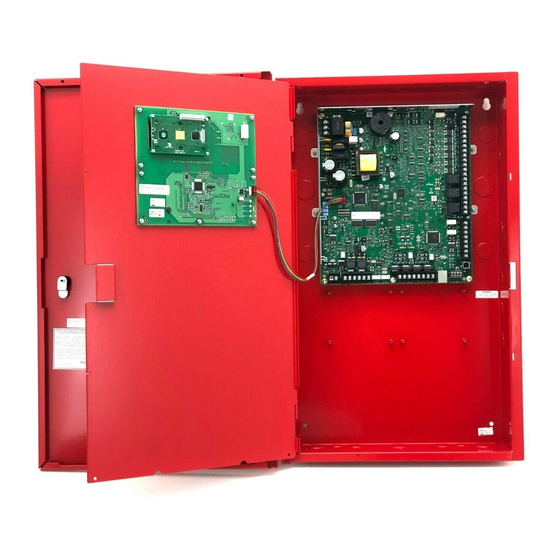
Page 27: Board Assembly Diagram
Model 6820 / 6820-EVS Installation Manual LS10144-001SK-E Board Assembly Diagram AC Power Input Circuits Flexput Relays Trouble Relay SBUS In/Out Battery Phone Lines EXT. COMM Connection Figure 3-2 Model 6820/EVS Assembly Figure 3-2 shows the circuit boards and annunciator. If you should need to remove the control board for repair, do so by removing the nuts that hold the heat sink bracket to into the cabinet. -
Page 28: Calculating Current Draw And Standby Battery
6.0 A. This is the maximum alarm current for the 6820 / 6820EVS control panel. If the current is above 6.0 A you will need to use a notification power expander(s) such as the Honeywell Silent Knight 5495 or the 5895XL intelligent power expander, to distribute the power loads so that the 6820 / 6820EVS or the power expanders do not exceed their power ratings. - Page 29 Model 6820 / 6820-EVS Installation Manual LS10144-001SK-E Table 3-2 Current Draw Worksheet for SK SLC Devices Standby Alarm Device # of Devices Current per Device Current Current Addressable SLC Detectors SK-PHOTO SK-PHOTO-T SK-HEAT SK-HEAT-HT Standby/Alarm: .30 mA SK-ACCLIMATE SK-HEAT-ROR SK-DUCT (includes PhotoR) Standby/Alarm: 2 mA...
- Page 30 LS10144-001SK-E Before You Begin Installation Table 3-2 Current Draw Worksheet for SK SLC Devices Standby Alarm Device # of Devices Current per Device Current Current SLC Modules Aux Pwr Standby: .5 mA B200SR Sounder Base Alarm: 35 mA Standby .3 mA Aux Pwr Standby: .5 mA...
- Page 31 Model 6820 / 6820-EVS Installation Manual LS10144-001SK-E Table 3-2 Current Draw Worksheet for SK SLC Devices Standby Alarm Device # of Devices Current per Device Current Current Standby: 10 mA EVS-SW24 Switch Expander (5 max.) Alarm: 25 mA Standby: 70 mA EVS-RPU Remote Paging Unit (4 max.) Alarm:...
-
Page 32: Current Draw Worksheet For Sd Slc Devices
LS10144-001SK-E Before You Begin Installation 1. The FACP can only support 5 devices w/LED’s on. This current draw has been added to the panels alarm current. 2. The SK-DUCT housing contains a vacant mount for a SK-RELAY (sold separately). Current draw for the SK-RELAY is calculated by increasing the SK-RELAY row of the calculation sheet by one for each SK-RELAY used with a SK-DUCT. - Page 33 Model 6820 / 6820-EVS Installation Manual LS10144-001SK-E Table 3-3: Current Draw Worksheet for SD SLC Devices Standby Alarm Device # of Devices Current per Device Current Current 5895XL Power Supply Standby/Alarm: 10 mA (16 max.) 5496 NAC Expander Standby/Alarm: 10 mA Standby: 35 mA 5865-4 LED Annunciator Module...
-
Page 34: Maximum Battery Standby Load
Maximum Battery Standby Load Table 3-4 and Table 3-5 show the standby load calculations for the 6820 / 6820EVS based on 24 and 90 hours of standby. The standby load calculations of line D in the Current Draw Calculation Worksheet must be less than the number shown in Table 3-4 and Table 3-5 for the selected battery size, standby hour and alarm time. -
Page 35: Control Panel Installation
Do NOT flush mount in a wall designated as a fire break. The 6820EVS cabinet can be surface or flush mounted. Cabinet overall dimensions are 21.592" W x 28.12" H. If you flush mount the cabinet, the backbox dimensions are 20"W x 26.5"H x 4.1"D There should be 1.5"... -
Page 36: Ethernet Connection
The AC terminals are rated at 120 VAC, 60 Hz, 2.7A. Figure 4-2 120 VAC Power Connection for the 6820 or 6820EVS... -
Page 37: Battery Power
Model 6820 / 6820-EVS Installation Manual LS10144-001SK-E Battery Power The batteries must be sealed lead acid type. Before connecting the batteries to the FACP, make certain that the interconnect cable between the batteries is not connected. Do not connect the battery jumper cable until the system is completely installed. - Page 38 LS10144-001SK-E Control Panel Installation • If using the battery cable extenders provided (P/N 140643), mount the RBB cabinet no more than 18" away from the main control panel cabinet. This will ensure that the bat- tery cables reach the battery terminals. Cabinet Mounting Holes Figure 4-4 RBB Cabinet Mounting Holes...
-
Page 39: Sbus Wiring
Model 6820 / 6820-EVS Installation Manual LS10144-001SK-E outs (on either the main control panel or the RBB cabinet), that are not previously being used may be uti- lized to connect conduit between the two cabinets. Connect battery leads to the backup battery terminals. See Figure 4-6. Observe the proper polarity to prevent damage to the batteries or the control panel. - Page 40 LS10144-001SK-E Control Panel Installation Table 4-1: SBUS Device Current Draw Model Number Worst Case Current Draw 5895XL Intelligent Power Supply .010 amps 5496 Intelligent Power Supply .010 amps EVS-50W .010 amps EVS-125W .010 amps EVS-100W .010 amps EVS-100W with EVS-100WBU .010 amps EVS-VCM / EVS-VCM with EVS-SW24* ** .080 amps / .105 amps...
- Page 41 Model 6820 / 6820-EVS Installation Manual LS10144-001SK-E where: Rpu = Ohms per 1000 feet for various wire gauges (see table below) Table 4-3: Typical Wire Resistance Per 1000 ft. Using Copper Wire Wire Gauge Ohms per 1000 feet (Rpu) 16.2 4.02 2.54 Wiring Distance calculation example:...
-
Page 42: Wiring Configurations
LS10144-001SK-E Control Panel Installation 4.4.2 Wiring Configurations Figure 4-8 illustrates Class A wiring configuration and Figure 4-9 illustrates Class B configuration. Caution For proper system supervision do not use looped wire under terminals marked A, B, +, and - of the SBUS device connectors. -
Page 43: 5860 Remote Annunciator Installation
5860 Remote Annunciator Installation The optional Model 5860 Remote Annunciator, is shown in Figure 4-10. Up to 16 annunciators can be added to the 6820 / 6820EVS system in any combination. Figure 4-10 Model 5860 Remote Annunciator, Front View 5860 installation involves the following steps: Make sure power is off at the panel. - Page 44 LS10144-001SK-E Control Panel Installation the following pages. Figure 4-11 Annunciator Parts The 5860 comes from the factory fully assembled. You must disassemble it for mounting. To disassemble the annunciator, use a 5/64 hex wrench to remove the set screws, located on the bottom of the annunciator bezel. (See Figure 4-12 for location of the set screws).
-
Page 45: Flush Mounting
Model 6820 / 6820-EVS Installation Manual LS10144-001SK-E 4.5.1.1 Flush Mounting This section of the manual describes flush mounting. You can flush-mount with or without an electrical box. Flush Mounting with an Electrical Box The 5860 annunciator can be used with the following types of electrical boxes: 4S, single-gang, and double- gang. -
Page 46: Surface Mounting
LS10144-001SK-E Control Panel Installation After the annunciator wiring to the panel has been completed (described in Section 4.5.2), replace the elec- tronic assembly in the back box. Place the bezel over the back box and tighten the set screws on the bezel. Attach second set of wires to top of back box. -
Page 47: Model 5860 Connection To The Panel
Model 6820 / 6820-EVS Installation Manual LS10144-001SK-E 4.5.2 Model 5860 Connection to the Panel Connect the 5860 to the panel as shown in Figure 4-15. Supervised Power Limited Figure 4-15 Model 5860 Connection to the Panel 4-13... -
Page 48: 6855 Remote Annunciator Installation
The optional Model 6855 Remote Annunciator, is shown in Figure 4-16. The 6855 can be surface or flush mounted. Up to 16 annunciators can be added to the 6820 or 6820EVS system in any combination. Figure 4-16 Model 6855 Remote Annunciator, Front View 6855 installation involves the following steps: Make sure power is off at the panel. -
Page 49: Flush Mounting
Model 6820 / 6820-EVS Installation Manual LS10144-001SK-E 4.6.1.1 Flush Mounting This section of the manual describes flush mounting. Follow these steps to flush mount the 6855 The back box dimensions are 9-9/32” W x 8-3/8” H. The minimum depth 2". The back box can be mounted prior to the complete installation of the 6855 using any of the mounting holes shown in Figure 4-17. -
Page 50: Surface Mounting
LS10144-001SK-E Control Panel Installation Attach the annunciator and door assembly to back box as shown in Figure 4-19 using the supplied screws. Figure 4-19 Attaching Annunciator/Door Assembly to Backbox 4.6.1.2 Surface Mounting The optional Model RA-100TG/TR trim ring kit is available for use when surface mounting. Remove the desired knock out. -
Page 51: Model 6855 Connection To The Panel
Model 6820 / 6820-EVS Installation Manual LS10144-001SK-E 4.6.2 Model 6855 Connection to the Panel Connect the 6855 to the panel as shown in Figure 4-21. Supervised Power Limited Figure 4-21 Model 6855 Connection to the Panel 6860 Remote Annunciator Installation The optional Model 6860 Remote Annunciator, is shown in Figure 4-22. -
Page 52: Mounting The 6860
LS10144-001SK-E Control Panel Installation Use the DIP switches on the back of the 6860 to assign an SBUS ID# to the 6860 (see Section 4.13.1). The 6860 module must be added to the system through programming. JumpStart AutoProgramming will add the module automatically (see Section 8.1). -
Page 53: Surface Mounting
Model 6820 / 6820-EVS Installation Manual LS10144-001SK-E Remove knockout holes as needed for wires. See Figure 4-24 for backbox knockout locations. Wire Knockouts Wire Knockouts Wire Knockouts Figure 4-24 Back Box Knockout Locations Wire the annunciator board to the main control panel. As described in Section 4.7.2. Attach the annunciator and door assembly to back box as shown in Figure 4-25 using the supplied screws. - Page 54 LS10144-001SK-E Control Panel Installation To properly mount the back box, insert a single screw into the key shaped mounting hole. Do not tighten all the way. See Figure 4-26. Place a level on top of the back box, with the back box level insert the rest of the mounting screws Key Shaped Mounting Hole Back Box...
-
Page 55: 6860 Connection To The Panel
Model 6820 / 6820-EVS Installation Manual LS10144-001SK-E 4.7.2 6860 Connection to the Panel Connect the 6860 to the panel as shown in Figure 4-28. Supervised Power Limited Figure 4-28 Model 6860 Connection to the Panel 5815XL Installation The 5815XL SLC expander lets you add 127 SD addressable devices The maximum number of SLC SD devices per panel is 635. -
Page 56: 5815Xl Connection To The Panel
LS10144-001SK-E Control Panel Installation Figure 4-29 is a drawing of the 5815XL board, showing the location of terminals and DIP switches. DIP Switch Figure 4-29 5815XL Board 4.8.1 5815XL Connection to the Panel Connect the 5815XL to the control panel as shown in Figure 4-30. After the 5815XL is connected to the panel, it must be added to the system. -
Page 57: 6815 Installation
Model 6820 / 6820-EVS Installation Manual LS10144-001SK-E 6815 Installation The 6815 SLC expander lets you add 159 SK detectors and 159 SK modules. The maximum number of SLC devices per panel is 1110. The number of 6815’s is limited by the maximum number of SBUS devices. Note: 6815 will only support SK or SWIFT™... - Page 58 LS10144-001SK-E Control Panel Installation be added to the system. This programming step is described in Section 4.13. Supervised Power Limited Figure 4-32 6815 Connection to Main Panel Assembly 4-24...
-
Page 59: 5824 Serial/Parallel Interface Module Installation
Model 6820 / 6820-EVS Installation Manual LS10144-001SK-E 4.10 5824 Serial/Parallel Interface Module Installation The 5824 serial/parallel interface module allows you to connect a printer to the panel, so you can print a real-time log of system events, detector status and event history. Instructions for installing the 5824 appear below. The 5824 and the printer connected to the 5824 Parallel port is ancillary, the serial port can be used for primary fire signaling. -
Page 60: 5880 Led I/O Module
The 5880 can drive up to 40 LEDs and has one PZT controller. The 5880 also has eight inputs for monitoring dry contacts. When used with the 6820EVS the 5880 inputs can be programmed to replicate the eight EVS buttons located on the front of the voice control module. (See section 9.5 for programming options). -
Page 61: 5880 Connection To Panel
Model 6820 / 6820-EVS Installation Manual LS10144-001SK-E connectors for connecting LEDs; and the DIP switch for selecting an SBUS ID number for the 5880. Dry Contact Inputs SBUS Address DIPs SBUS Connection Figure 4-35 5880 Board Layout 4.11.2 5880 Connection to Panel The 5880 connects to the panel via the SBUS. -
Page 62: Led Wiring
LS10144-001SK-E Control Panel Installation 4.11.3 LED Wiring There are four 12-pin connectors on the 5880 board for connecting LEDs. Each LED gets its power from Pin 11. Internal resistors are sized so that there is approximately 10 mA of current for each LED, no series resistors are required. - Page 63 Model 6820 / 6820-EVS Installation Manual LS10144-001SK-E inputs. Supervised 4.7k EOL Figure 4-38 Dry Contact Wiring 4-29...
-
Page 64: 5865-3 / 5865-4 Led Annunciator Installation
LS10144-001SK-E Control Panel Installation 4.12 5865-3 / 5865-4 LED Annunciator Installation The 5865-3 and 5865-4 are LED annunciators. The 5865-4 has 30 mappable LEDs, remote silence and reset key switches, and a general system trouble LED. The 5865-3 has 30 mappable LEDs only. These are arranged as 15 pairs of red (typically used for alarm) and yellow (typically used for trouble) LEDs. - Page 65 Model 6820 / 6820-EVS Installation Manual LS10144-001SK-E Figure 4-41, the 5865-4 attached to a 4-gang box is used as an example. Figure 4-41 5865 Mounting Example The 5865 ships with a set of zone description labels that can be inserted into the 5865 board assembly. These labels can be used in a typewriter or can be written on by hand.
-
Page 66: Configuring Sbus Modules
Each SBUS device generates a certain amount of traffic on the SBUS. Generally, the amount of traffic generated depends on the type of SBUS device. To help you figure out the SBUS bandwidth usage of a given collection of devices, a tool is available on the Honeywell Silent Knight website (www.silentknight.com). The tool will serve 4-32... -
Page 67: Telephone Connection
5859XL SBUS repeaters in your list of devices for SBUS bandwidth calculations. 4.14 Telephone Connection Connect the telephone lines as shown in Figure 4-44. The Model 7860 phone cord is available from Honeywell Silent Knight for this purpose. A number of programmable options are available for customizing telephone lines. -
Page 68: Class A Inputs
LS10144-001SK-E Control Panel Installation Configure the circuit through programming (see Section 9.5). Supervised Power Limited UL Listed EOL 4.7 k Figure 4-45 Class B Input Switches 4.15.2 Class A Inputs You can connect conventional Class A switches, such as waterflow switches and pull stations, directly to the Flexput circuits of the control panel. -
Page 69: Installing 2-Wire Smoke Detectors
Model 6820 / 6820-EVS Installation Manual LS10144-001SK-E Note: In programming any point that uses multiple Flexput circuits, the lowest Flexput circuit number is used to refer to the circuit pair. In this example, Figure 4-46 uses both Flexput circuit 5 and 6, so in programming it would be referred to as point 5. -
Page 70: Installing 4-Wire Smoke Detectors
LS10144-001SK-E Control Panel Installation Note: In programming any point that uses multiple Flexput circuits, the lowest Flexput circuit number is used to refer to the circuit pair. In this example, Figure 4-48 uses both Flexput circuit 5 and 6, so in programming it would be referred to as point 5. - Page 71 Model 6820 / 6820-EVS Installation Manual LS10144-001SK-E Smoke power is supplied to each Class A loop as shown in Figure 4-50. Air Products PAM-2 Model 160150 Supervision Module Figure 4-50 Class A 4-Wire Smoke Detector Connections Note: In programming any point that uses multiple Flexput circuits are always referred to as the lowest Flexput circuit number used.
-
Page 72: Conventional Notification Appliance
LS10144-001SK-E Control Panel Installation 4.16 Conventional Notification Appliance This sub-section of the manual explains how to install conventional notification appliances for Class A and Class B configurations. 4.16.1 Class B Notification Wiring You must use an appliance from the list of compatible appliances in the Appendix A at the back of this manual. To install a Class B Notification appliance circuit: Wire Class B Notification appliances as shown in Figure 4-51. -
Page 73: Auxiliary Power Installation
Model 6820 / 6820-EVS Installation Manual LS10144-001SK-E Wire the Class A notification appliances as shown in Figure 4-52. Caution For proper system supervision do not use looped wire under terminals marked – and + of the NAC connectors. Break wire runs to provide supervision of connections. Configure the circuit for Class A in programming (see Section 9.4.1). -
Page 74: Door Holder Power
LS10144-001SK-E Control Panel Installation Wire the circuit(s) that will be used for auxiliary power. Configure the auxiliary power output through programming (see section 9.5). 4.16.3.1 Door Holder Power Door holder power is intended for fire door applications. When there are no fire system alarms in the system and the panel has AC power, door holder circuits have 24 volt power present at their terminals. -
Page 75: Programmable Relays
Model 6820 / 6820-EVS Installation Manual LS10144-001SK-E 4.17.2 Programmable Relays The control panel has two Form C programmable relays built into terminals labeled RELAY and RELAY 2. Each relay provides a normally open and a normally closed contact. To install one or two programmable relays, follow these steps. Wire Relay 1 and/or Relay 2 as needed for your application. - Page 76 LS10144-001SK-E Control Panel Installation an enclosure that contains a manually operated transmitter used to send an alarm to the municipal communication center which houses the central operating part of the fire alarm system. City Box Standby Current: 0 (Notification supervision current accounted for in control panel draw). Alarm Current: 1 Amp for 1 second 27.2 VDC max The maximum coil and wire resistance (combined) must not exceed 30 ohms.
-
Page 77: Using The Addressable Relay Module For City Box Connection
Model 6820 / 6820-EVS Installation Manual LS10144-001SK-E 4.18.3 Using the Addressable Relay Module for City Box Connection Wire the SK-Relay as shown in Figure 4-56. Figure 4-56 Relay Module for City Box Connection 4.18.4 NFPA 72 Polarity Reversal Note: Intended for connection to a polarity reversal circuit of a control unit at the protected premises having compatible rating. -
Page 78: Using The 7644-L8 Module
LS10144-001SK-E Control Panel Installation If necessary, adjust loop current using the potentiometer (R10) on the 5220 board. Normal loop current is 2- to-8 mA with a 1k ohm remote station receiving unit. Maximum loop resistance is 3k ohm. All circuits power-limited. All wiring supervised. -
Page 79: Transmitter Activated By Dry Contacts
4.18.5 Transmitter Activated by Dry Contacts This section describes the connection of a UL 864 listed remote station transmitter to the 6820/6820EVS FACP dry contacts. The FACP contacts must be supervised by the remote station transmitter module using end-of-line resistors (ELRs) with a value determined by the transmitter manufacturer. Power is also provided by the remote station transmitter manufacturer. -
Page 80: Common Communication Link
Model 6820 / 6820-EVS Installation Manual LS10144-001SK-E Section 5 Common Communication Link Hardware Features 6820/EVS panels can be networked to create a virtual system that is larger than 1,110 addressable points. Each additional 6820/EVS provides another 1,110 addressable points to the network total. For example, a network of 17- 6820/EVS panels provides a maximum addressable point capacity of 18,870 points (1,110 x 17 = 18,870 SK devices). -
Page 81: Sk-Nic Connection Options
LS10144-001SK-E Common Communication Link SK-NIC Connection Options When linking a group of 6820/EVS’s you must use the SK-NIC to link the panels together. See Figure 5-1 and Figure 5-2, for Internal mounting or external mounting of SK-NIC option. Must be in Conduit 2’... -
Page 82: Sk-Nic Wiring Options
Model 6820 / 6820-EVS Installation Manual LS10144-001SK-E SK-NIC Wiring Options Linking a group of 6820/EVS requires the use of a SK-NIC network interface card with each panel. The SK-NIC connects to other linked units using unshielded, twisted-pair wiring or fiber-optic cable. Figure 5-3 SK-NIC Network Interface Card 5.3.1 Fiber Loop Modules... -
Page 83: Sk-Nic-Kit Mounting Kit
The SK-NIC is designed to mount on one of the SLC expander standoff sets inside the cabinet or remotely using the SK-NIC-KIT. Use the following steps to properly mount the SK-NIC inside the 6820 or 6820EVS. Place the SK-NIC on one of the SLC expander standoff sets. - Page 84 Figure 5-8, Figure 5-9, and Figure 5-10 for SK-NIC wiring examples. To mount the SK-NIC remotely: Follow the steps above except, The 6-pin cable that runs from the SK-NIC to the 6820EVS must be run in conduit. See Figure 5-1.
-
Page 85: Unshielded Twisted Pair Wiring Between Multiple Panels
LS10144-001SK-E Common Communication Link 5.3.2.1 Unshielded Twisted Pair Wiring between Multiple Panels Unshielded twisted pair wiring between multiple panels is shown in Figure 5-7. Class A wiring is shown with a dotted line. Class A wiring Figure 5-7 Twisted Pair Wiring Configuration... -
Page 86: Fiber Optic Multi-Mode Wiring Between Multiple Panels
Model 6820 / 6820-EVS Installation Manual LS10144-001SK-E 5.3.2.2 Fiber Optic Multi-Mode Wiring between Multiple Panels Fiber optic cable between multiple panels is shown in Figure 5-8. Class A is shown with a dotted line. Class A wiring Figure 5-8 Fiber Optic Wiring Example... - Page 87 LS10144-001SK-E Common Communication Link Class A wiring Figure 5-9 Fiber Optic Wiring Single-Mode Example...
-
Page 88: Fiber Optic And Twisted Pair Wiring Between Multiple Panels
Model 6820 / 6820-EVS Installation Manual LS10144-001SK-E 5.3.2.3 Fiber Optic and Twisted Pair Wiring between Multiple Panels A mixture of fiber optic cable and twisted pair wiring between multiple panels is shown in Figure 5-10. Class A cabling is shown with dotted line. Class A wiring Figure 5-10 Twisted Pair and Fiber Optic Combination Wiring Example... -
Page 89: Setting The Panel Id For Each Panel
LS10144-001SK-E Common Communication Link Setting the Panel ID for each Panel Note: It is important that much thought is given when choosing the panel IDs for each panel. It is difficult to change the IDs once panel programming has begun. The panel ID for each panel is set using DIP switch positions 1 through 5. -
Page 90: Network Management
Network Programming This section of the manual describes how to program network options using the built-in annunciator. All options described in this section can be programmed using the HFSS Honeywell Fire Software Suite. To edit site assignments, HFSS must be utilized. -
Page 91: Edit Network Names
An installer at the panel site can initiate communications between the panel and a computer running the HFSS Honeywell Fire Software Suite (see also Section 10.1). In order for this communication to function properly, both the computer (running the software) and the control panel must have matching computer access numbers and computer codes. - Page 92 Model 6820 / 6820-EVS Installation Manual LS10144-001SK-E other users may only need access to lower level functions such as preforming fire drills, or acknowledging trouble conditions. Profile 1 is the profile that dictates what functions the Fire Fighter Key has access to. Because this is the profile for a key, the user name and the access code can not be edited for this profile.
-
Page 93: Edit Name
LS10144-001SK-E Network Management Display reads: Select Profile 01 Fire Fighter’s Key Select the access code you wish to edit by pressing the up or down arrow key. Then press ENTER. Profile Edit Menu From the Profile Edit Menu you can change the users name, access code, and the panel functions that the user will have access to with their code. -
Page 94: Communicator Miscellaneous
Model 6820 / 6820-EVS Installation Manual LS10144-001SK-E 6.2.6.2 Communicator Miscellaneous When using the SIA reporting format, the communicator sends information according to the SIA Reporting Type. The selections for this option are: pi modifier (default) Panel ID* Note: *Only SIA sends the panel ID when reporting. 6.2.6.3 Receiver Configuration The 6820/EVS system can report events to as many as 68 receivers. -
Page 95: Voice Options
LS10144-001SK-E Network Management Press * to add rows, Press ENTER to edit data Figure 6-1 Communicator Reporting (4x20 screen) Voice Options 6.3.1 Edit Timers Enter the installer code. The panel will automatically go to the main menu. Select 6 for Network Programming. Select 7 for Voice Options. -
Page 96: Edit Voice Commands
Model 6820 / 6820-EVS Installation Manual LS10144-001SK-E Table 6-2 Auto Reset EVS MIC Triggered Event Timer Menu EVS Timer Option Control Lockout Immediate/Timer/Never Auto Reset EVS MIC Triggered Event Never/Timer/Event Disabled Auto Reset EVS Event 1 Never/Timer/Event Disabled Auto Reset EVS Event 2 Never/Timer/Event Disabled Auto Reset EVS Event 3 Never/Timer/Event Disabled... - Page 97 LS10144-001SK-E Network Management Table 6-3 Voice Command Mapping System Event Fire Alarm Fire System Aux 1 Fire System Aux 2 Fire Zone Aux 1 Fire Zone Aux 2 Fire Pre Alarm Emergency Communication 1 Emergency Communication 2 Emergency Communication 3 Emergency Communication 4 Emergency Communication 5 Emergency Communication 6...
-
Page 98: Sync Network Options
Figure 6-2 Sync Network Options on a 6820 - 4 x 20 screen If 2 panels have the Last time the date & time were same chk sum, network updated on the panel. options are in sync. Figure 6-3 Sync Network Options on a 6820EVS - 4 x 40 screen... - Page 99 LS10144-001SK-E Network Management Network Management Quick Reference Menu Options/Defaults Comments Learn Guest or member Add or remove See Section 6.2.1 panels into the Network network Edit Panel Names Network Panel ID Edit Panel Names See Section 6.2.2 Network Site Names Edit Site Member Edit Site Names Names...
- Page 100 Model 6820 / 6820-EVS Installation Manual LS10144-001SK-E Menu Options/Defaults Comments Network Profile 1 is the profile that Programming dictates what functions the Firefighter Key has access to. Panel Programming Because this is the profile for a System Information keys, the user name and the access code can not be edited Multi-Site for this profile.
- Page 101 LS10144-001SK-E Network Management Menu Options/Defaults Comments Immediate/ Control Lockout Timer/ Never Edit Timers Auto Reset EVS See Section 6.3.1 Never/ Event 1-8 Timer/Event Auto Reset EVS MIC Disabled Triggered Event Fire Alarm Fire System Aux 1 Fire System Aux 2 Fire Zone Aux 1 Fire Zone Aux 2 Fire Interlock Release...
-
Page 102: Sk, Sd And Swift™ Wireless Slc Device Installation
Model 6820 / 6820-EVS Installation Manual LS10144-001SK-E Section 7 SK, SD and SWIFT™ Wireless SLC Device Installation Caution! To avoid the risk of electrical shock and damage to the unit, power should be OFF at the control panel while installing or servicing. -
Page 103: List Of Sd Slc Devices
LS10144-001SK-E SK, SD and SWIFT™ Wireless SLC Device Installation Table 7-1: SK SLC Devices Installation Model Name/Description Part Number Instruction PN B200S Sounder Base I56-3387-00 B201LP 6" mounting base I56-0595-00 B224BI 6" isolator base I56-0725-00 B224RB 6" relay base I56-3737-00 B200SR Sounder base I56-3392-00... -
Page 104: Swift Wireless Slc Devices
The WSK-WGI Wireless Gateway acts as a bridge between a group of wireless fire devices and a SLC loop on the 6820 /6820EVS. It is powered by the SLC loop or by a regulated, external 24VDC UL-listed power supply. Available wireless devices include a photo detector, a photo/heat detector, a fixed-temperature heat detector, a rate-of-rise detector, and a monitor module. -
Page 105: Wire Sizing For 6815
SK Modules The 6820 or 6820EVS SLC can be programmed to operate in SK mode. While shielded wire is not required, it is recommended that all SLC wiring be twisted-pair to minimize the effects of electrical interference. Use Table 7- 4 to determine the specific wiring requirements for the SLC. - Page 106 Model 6820 / 6820-EVS Installation Manual LS10144-001SK-E Figure 7-1 and Figure 7-2 show how wire length is determined for out & back tap and T-Tap. Figure 7-1 Calculating wire run length for a simple out and back When using T-taps, the total length of all taps and the main bus must not exceed 40,000 feet. This requirement must be met in addition to the maximum distance requirements for the various wire gauges.
-
Page 107: Wiring 5815Xl Or 6815 In Class A Configuration
LS10144-001SK-E SK, SD and SWIFT™ Wireless SLC Device Installation 7.5.4 Wiring 5815XL or 6815 in Class A Configuration Figure 7-3 illustrates how to wire the SLC loop for Class A installations. Note: Class A wiring also requires an isolator module as the first device on the in and the out loops. Note: No t-taps allowed on class A SLC loops. -
Page 108: Addressing Sk Slc Devices
Model 6820 / 6820-EVS Installation Manual LS10144-001SK-E Addressing SK SLC Devices All SK devices are addressed using the two rotary dials that appear on the device board. Use the ONES rotary dial to set the ones place in a one or two digit number, and use the TENS rotary dial to set the tens place in a two or three digit number. -
Page 109: Addressing Sd Slc Devices
LS10144-001SK-E SK, SD and SWIFT™ Wireless SLC Device Installation Set the address for each device as described in Section 7.9. Figure 7-6 Heat or Smoke Detector Connection to the FACP Addressing SD SLC Devices This section tells how to address detectors and modules. See Table 7-2 for a list of detectors that are easily addressed at the FACP. -
Page 110: Slc Devices With Dip Switches
Model 6820 / 6820-EVS Installation Manual LS10144-001SK-E When the wait message clears, the following options display: 1- for Read Address. Use to read (or check) a single detector’s address. 2- for Write Address. Use to program a single detector’s address. 3- for Seq. -
Page 111: Sk-Wgi Wireless Gateway
LS10144-001SK-E SK, SD and SWIFT™ Wireless SLC Device Installation 7.10 SK-WGI Wireless Gateway Note: The SK-WGI, as part of the wireless network, has been tested for compliance with the Federal Communi- cations Commission (FCC) requirements of the United States Government. It has not been evaluated for use outside the USA. -
Page 112: Programming Overview
Model 6820 / 6820-EVS Installation Manual LS10144-001SK-E Section 8 Programming Overview This section of the manual is intended to give you an overview of the programming process. Please read this section of the manual carefully, especially if you are programming the control panel for the first time. ®... -
Page 113: Running Jumpstart Autoprogramming
LS10144-001SK-E Programming Overview Circuit 8 (Relay 2): ® Assigned to Group 999. JumpStart automatically programs Zone 1 to activate Group 999 using constant on output when an alarm occurs. Amplifier Circuits: ® Assigned to Group 2.JumpStart automatically programs Zone 1 to activate Group 2. Addressable output points (Relay modules): All addressable relay devices will be configured as “Output Pt”... -
Page 114: Mapping Overview
Model 6820 / 6820-EVS Installation Manual LS10144-001SK-E Mapping Overview This section of the manual is a high level overview of mapping. Mapping is an important concept with the control panel. In general terms, mapping is assigning or linking events to outputs that will activate when events occur. You do this by assigning input points to input zones, output points to output groups and then linking or mapping zones and output groups. -
Page 115: Input Point Mapping
LS10144-001SK-E Programming Overview 8.2.1 Input Point Mapping Input points are assigned to input zones, as the example in Figure 8-2 shows. Any input point can be assigned to any input zone. (Input points can be assigned to one zone only. An input point can be designated as “Unused,” which means it has not been assigned to a zone). -
Page 116: Output Circuit Mapping
Model 6820 / 6820-EVS Installation Manual LS10144-001SK-E 8.2.2 Output Circuit Mapping Figure 8-3 is a simple example showing how to assign notification and relay output circuits to groups. For an example of a simple floor above/floor below application, see Figure 8-5. Figure 8-3 Example of Assigning Output Circuits to Groups... -
Page 117: Event Mapping
LS10144-001SK-E Programming Overview 8.2.3 Event Mapping There are 11 types of Zone events 14 types of Panel events, and 6 types of Site events that can be mapped (see Table 8-1). For each event type, you can activate output groups and patterns. Mapping examples are shown in Figure 8-4, Figure 8-5 &... - Page 118 Model 6820 / 6820-EVS Installation Manual LS10144-001SK-E Figure 8-4 Example of Zone Events Mapped to Output Groups and Patterns...
- Page 119 LS10144-001SK-E Programming Overview Figure 8-5 Example of Zone Events Mapped to Output Groups and Patterns...
-
Page 120: Mapping Led Points
Programming Using the HFSS Software Suite You can use the HFSS Honeywell Fire Software Suite to program the control panel onsite (personnel will need to be onsite during the upload or download process). HFSS is a software package that lets you easily program the control panel using a Windows-based computer. -
Page 121: Entering / Exiting The Program Menu
5860, 6860 & 6855 remote annunciator. Note: Mapping cannot be programmed through the on-board and remote annunciators. Mapping is only avail- able through HFSS Honeywell Fire Software Suite up/downloading software. The following subsections describe programming basics, including a description of editing keys available for programming and how to move through programming menus. -
Page 122: Programming Menu Quick Reference
Model 6820 / 6820-EVS Installation Manual LS10144-001SK-E Press Enter text (alphanumeric data) See Appendix B for complete list of characters. Select from a scrolling list The up or down arrow to move through the list of available options. When the option you want to select is displayed, press ENTER. - Page 123 LS10144-001SK-E Programming Overview Table 8-2: Programming Quick Reference Table Menu Options/Defaults Comments Edit Zone Name Section 9.3.1.1 *1-Count 2-Count Alarm Ver. Verification Section 9.3.1.2 Type Zone SNGL ILOCK Properties DBL ILOCK SD devices 135° to 150°F Section 9.3.1.2 Heat Temp Edit Zone Select Zone Zone...
- Page 124 Model 6820 / 6820-EVS Installation Manual LS10144-001SK-E Table 8-2: Programming Quick Reference Table Menu Options/Defaults Comments UNUSED MANUAL PULL *LATCH WATERFLOW NON-LATCH *LATCH FIRE SUPERVSY NON-LATCH FIRE DRILL SILENCE RESET P.A.S. ACK *LATCH ZONE AUX1 NON-LATCH *LATCH SD and SK ZONE AUX2 NON-LATCH Devices on...
- Page 125 LS10144-001SK-E Programming Overview Table 8-2: Programming Quick Reference Table Menu Options/Defaults Comments *LATCH EVS TAMPER NON-LATCH 1,2,3, SWITCH *LATCH EVS SUPER- VISORY NON-LATCH Select Module OUTPUT PT Select Group AUX CONST 1,2,3,4, NOTIF AUX RESET AUX DOOR OUTPUT PT Select Group 1,2,3,4,5,6 1,2,3,4, RELAY...
- Page 126 Model 6820 / 6820-EVS Installation Manual LS10144-001SK-E Table 8-2: Programming Quick Reference Table Menu Options/Defaults Comments No Accessory SDR BAS 1,2,3,4,5 RLY BAS 1,2,3,4,5 HEAT 1,2,3,4,5 I-SdrBa (Intelligent Sounder 2,3,4 Base) No Accessory PHOTO 1,2,3,4,5 DUCT DCT RLY No Accessory SDR BAS RLY BAS ACCLIMATE...
- Page 127 LS10144-001SK-E Programming Overview Table 8-2: Programming Quick Reference Table Menu Options/Defaults Comments No Accessory SDR BAS RLY BAS CO ALARM/ FIRE ALARM I-SdrBA (Intelligent Sounder Base) No Accessory SDR BAS RLY BAS CO ALARM/ FIRE SUPR I-SdrBA (Intelligent Sounder Base) 2,3,4 CO FIRE No Accessory...
- Page 128 Model 6820 / 6820-EVS Installation Manual LS10144-001SK-E Table 8-2: Programming Quick Reference Table Menu Options/Defaults Comments SLC LED LED Output LED Function (SD only) UNUSED NOTIF Select Group OUTPUT B NOTIF Super-vised CONTROL Yes or No CIRCUIT NOTIF Section 9.5 Select Group OUTPUT A NOTIF...
- Page 129 LS10144-001SK-E Programming Overview Table 8-2: Programming Quick Reference Table Menu Options/Defaults Comments EVS TAMPER Latch and Non-Latch feature only appear for EVS SUPER- WATERFLOW,FIRE VISORY SUPERVISORY, FIRE TAMPER, ZONE AUX1, ZONE AUX2, SYSTEM AUX1, STATUS SYSTEM AUX2., EVS INPUT, POINT EVS TAMPER, and EVS SUPERVISORY Enter Pt /Select Function...
- Page 130 Model 6820 / 6820-EVS Installation Manual LS10144-001SK-E Table 8-2: Programming Quick Reference Table Menu Options/Defaults Comments Address Subn Mask SubNet Edit Ethernet Section 9.6.1.3 Default Gateway DHCP Enable 75 sec, 90 Sec, 3 min, 5 Ethernet Supervise min, 1 hr, 24 *5 Minutes hrs, 30 days, None...
- Page 131 LS10144-001SK-E Programming Overview Table 8-2: Programming Quick Reference Table Menu Options/Defaults Comments SYNC Strobes when Section 9.6.3.1 Silenced Miscellaneous Options Auto Display Events Section 9.6.3.2 Auto Daylight Saving System Section 9.6.4.1 Time Options Daylight Saving cont Options DST Start Select week: 1st, 2nd, Select month Section 9.6.4.2 3rd, 4th or Last...
-
Page 132: Programming
This section of the manual describes how to manually program the control panel from the built-in annunciator. Each subsection discusses these menu options in detail. All options described in this section can be performed using HFSS Honeywell Fire Software Suite. Important! ®... -
Page 133: Modules
LS10144-001SK-E Programming Modules This section lists the options available under the module option in the program menu. The following modules are available for the control panel: 6815 & 5815XL SLC expander, 5860, 6860 & 6855 remote fire alarm annunciators, 5824 serial/parallel printer interface module, 5496 intelligent power module, 5895XL intelligent power module, 5880 LED I/O module, and 5865 LED annunciator, EVS-50W, EVS-100W, EVS-INT50W or EVS-125W audio/voice amplifiers, EVS-VCM voice control module, SK-NIC network interface card, and EVS- RVM remote voice module. -
Page 134: Adding A Module
Model 6820 / 6820-EVS Installation Manual LS10144-001SK-E Option settings are edited by pressing the up or down arrow. 9.2.2 Adding a Module To add a new hardware module to the system, follow these steps: You must be in the Main Menu to perform this task. If necessary, enter the Installer Code. Enter the installer code. -
Page 135: Zone
Press 2 to edit the properties of the selected zone. Figure 9-2 Editing Zone Properties Alarm Delay Characteristics The programmed zone type is provided for user reference only. To modify the zone type, use the HFSS Honeywell Fire Software Suite. - Page 136 Model 6820 / 6820-EVS Installation Manual LS10144-001SK-E Table 9-1 list the detector characteristics and a description of each. Table 9-1: Alarm Detector Characteristics Type of Delay Description One Count (No Delay). When this option is enabled, an alarm occurs immediately when a single device of any of the following types goes into alarm: detector, manual pull, water flow, 1-Count Zone Aux1 or Zone Aux2.
-
Page 137: Zone Accessory Options
LS10144-001SK-E Programming Use the up or down arrow key to scroll through the range or enter directly from the number keys on the annunciator, then press ENTER. 9.3.1.3 Zone Accessory Options Do steps 1 through 5 of Section 9.3.1. Press 3 to edit the Zone’s Accessory options. Single or Multi-Station cadence pattern (choose from Patterns 00 to 02, 23 if using SK. -
Page 138: Edit Group Name
Model 6820 / 6820-EVS Installation Manual LS10144-001SK-E Press 3 to enter group menu. Press 1 to edit group. Enter the number of the group you wish to edit, then press ENTER. 9.4.1.1 Edit Group Name To edit the group name, press 1. You can use words to display a descriptive name for a group. -
Page 139: View Group Points
LS10144-001SK-E Programming single button press. See 11.2.3.2. Corresponding Corresponding Key and LED Numbers Key and LED Numbers EVS-SW24 EVS User Interface Figure 9-4 Corresponding Key and LED for Mapping Output Groups Silencing Options The following silencing options are available for each output group. Table 9-2: Silencing Options Optional Description... -
Page 140: Edit Opg Template
Model 6820 / 6820-EVS Installation Manual LS10144-001SK-E 9.4.3 Edit OPG Template Enter the installer code. The panel will automatically go to the main menu. Select 7 for Panel Programming. Press 3 to enter group menu. Press 3 to edit OPG Template. Enter the Template number, then press ENTER Press ENTER on the template name to edit the name. -
Page 141: Point
LS10144-001SK-E Programming Point You may need to change characteristics of individual input points (detectors and switches) even after using ® JumpStart . This section explains how to change options for: type of point, latching/non-latching, silenceable/ non-silenceable, zone assignment (input points), detector accessory base options, group assignment (output points), and point name. - Page 142 Model 6820 / 6820-EVS Installation Manual LS10144-001SK-E Table 9-3: Programming Options for 5815XL Modules Type Function Latching Option Comments Selection Use this switch type for manual pull stations. This input is always latched. The switch can clear only when an alarm is reset. This MANUAL PULL switch type has the highest fire priority;...
-
Page 143: Point Programming For 6815 Module
LS10144-001SK-E Programming Table 9-3: Programming Options for 5815XL Modules Type Function Latching Option Comments Selection INTERLOCK Interlock release switch input. STATUS POINT EVS INPUT Latching User also has EVS Event Number 1-8 option for EVS INPUT. Non Latching Only available when an EVS-VCM is installed in the system. EVS TAMPER Latching SWITCH... - Page 144 Model 6820 / 6820-EVS Installation Manual LS10144-001SK-E Select the type of device by pressing the up or down arrow key. Refer to Table 9-4 under the column heading “Type Selection” for a list of choices. Table 9-4 Point Programming for 6815 Type Function Latching Option...
- Page 145 LS10144-001SK-E Programming Table 9-4 Point Programming for 6815 Type Function Latching Option Comments Selection Latching Use this switch type for tamper monitoring of sprinklers and other FIRE SUPER- fire protection devices. If a contact closes, a sprinkler supervisory VISORY event will be generated. Supervisory switches can be latching or Non Latching non-latching.
-
Page 146: Point Programming For Internal Or External Power Module
Model 6820 / 6820-EVS Installation Manual LS10144-001SK-E Table 9-4 Point Programming for 6815 Type Function Latching Option Comments Selection Output point, a general use notification type. Use for driving OUTPUT PT Select Group standard notification appliances. Use constant power for applications that require a constant auxiliary AUX CONST power source. - Page 147 LS10144-001SK-E Programming 10. Repeat steps 1 through 9 for all circuits. Table 9-5: Menu choices for Internal/External Power Module Function Choices Type Selections Selections for Comments each Type Enter Point UNUSED B NOTIF NOTIF Output Control Circuit A NOTIF CONSTANT Constant auxiliary power.
-
Page 148: Point Programming For 5880, 5865, Evs-50W, Evs-Int50W, Evs-100W, Evs-125W And Evs-Ce4 Modules
Model 6820 / 6820-EVS Installation Manual LS10144-001SK-E 9.5.4 Point Programming For 5880, 5865, EVS-50W, EVS-INT50W, EVS-100W, EVS-125W and EVS-CE4 Modules To program 5880, 5865, EVS-50W, EVS-INT50W, EVS-100W, EVS-125W, or EVS-CE4 module points: Enter the installer code. The panel will automatically go to the main menu. Select 7 for Program Menu. -
Page 149: System Options
LS10144-001SK-E Programming Use the up or down arrows to modify and remaining options and use ENTER to move to the next field. Edit module name. See Section 9.2.1.2. or, Press the right arrow to skip module name edit. 10. Repeat Steps 1 through 9 for all points. Table 9-6: Point Programming Options for EVS-VCM and EVS-RVM Function Selections Choices... -
Page 150: Phone Lines
Model 6820 / 6820-EVS Installation Manual LS10144-001SK-E From the next menu, select 1 for Communication Options. Select 1 for Auto Test Time. Enter the hour you desire the control panel to send an automatic test report (or press the up or down arrow key), then press ENTER. - Page 151 Number of Answer Rings This option is used in conjunction with the HFSS Honeywell Fire Software Suite. Use this option to determine the number of rings before the panel answers a call from the computer. Range is 00-15 rings. This option is factory-programmed as 06 rings, which should be compatible for most installations where the answering machine bypass feature is used.
-
Page 152: Edit Ethernet
Model 6820 / 6820-EVS Installation Manual LS10144-001SK-E 13. Select Y (answering machine bypass enabled) or N (answering machine bypass disabled) by pressing the up or down arrow key, then press ENTER. Phone Line Unused This option is used so that you can set unused phones lines to “Yes”, so no auto-test will be sent through that line. This option is factory programmed as No. -
Page 153: Phone Line Gains
LS10144-001SK-E Programming 9.6.1.5 Phone Line Gains Enter the installer code. The panel will automatically go to the main menu. Select 7 for Panel Programming. Select 5 for System Options. From the next menu, select 1 for Communication Options. Select 5 for Phone Line Gains The available options: *default •... -
Page 154: Alarm Verify
Model 6820 / 6820-EVS Installation Manual LS10144-001SK-E 9.6.2.2 Alarm Verify You can set the alarm verification time from 60 to 250 seconds (default is 60 seconds). To set the alarm verification: Enter the desired number of seconds for the alarm verification time. Press the right arrow ENTER to make your selection and move to the next programming option. -
Page 155: Synchronize Strobes Active During Silence
LS10144-001SK-E Programming 9.6.3.1 Synchronize Strobes Active During Silence When “SYNC Strbs w/ Sil:” is Selected as Y (Yes) then strobes will continue to flash when the system is silenced and will stop flashing when the system is reset. Note: The “SYNC Strbs w/ Sil:” only functions with outputs that use a synchronized output pattern. Press the up or down arrow to toggle this selection between Y (Yes) or N (No). -
Page 156: Edit Banner
SLC Family The 6820/6820EVS supports SD protocol SLC devices or SK protocol SLC devices. You must configure the 6820/6820EVS to accept the protocol of the devices you are installing. You cannot mix SLC devices of different protocols. Note: You cannot mix SK and SD protocol SLC devices on the same panel. -
Page 157: Restore Defaults
LS10144-001SK-E Programming ® more devices, when you JumpStart again the additional devices are added but you do not lose any of your previous custom programming ® To run JumpStart Enter the installer code. The panel will automatically go to the main menu. Select 7 for Panel Programming. -
Page 158: System Operation
Model 6820 / 6820-EVS Installation Manual LS10144-001SK-E Section 10 System Operation Operation of the control panel is simple. Menus guide you step-by-step through operations. This section of the manual is an overview of the operation menus. Please read this entire section carefully before operating the panel. -
Page 159: Lcd Display
LS10144-001SK-E System Operation Figure 10-2 shows the annunciator that is part of the control panel board assembly for the 6820EVS. Figure 10-2 Control Panel Annunciator for 6820EVS 10.2.1 LCD Display The control panel LCD displays system messages, annunciates alarms, supervisories and troubles, provides status information, and prompts for input. -
Page 160: Menu System
Internal Banner Custom Banner Example Figure 10-4 Banner Display Examples for 6820EVS 10.3 Menu System The control panel is easy to operate from the Main Menu. To view the Main Menu press the ENTER or right arrow key on the control panel or remote annunciator. The Main Menu will appear as shown in Section 10.3.1. -
Page 161: Using The Menus
LS10144-001SK-E System Operation 10.3.2 Using the Menus To move through the menus: the up or down arrows the left to move through the options in a menu. Use arrow to move to a previous menu. To select an option: Enter the number of the option, OR press ENTER if the option has the = symbol next to it. -
Page 162: Inhibit Output Group
In networked setups, each panel stores up to 1000 of its own events. When using HFSS Honeywell Fire Software Suite, all 1000 events from every panel in the network will be uploaded. -
Page 163: Conduct A Walk Test
LS10144-001SK-E System Operation Press 2 for Indicator Test. The system turns on each LED several times, beeping the PZT as it does so. At the same time it scrolls each available character across the LCD. A problem is indicated if any of the following occurs: •... -
Page 164: Manual Alarmnet Registration
Model 6820 / 6820-EVS Installation Manual LS10144-001SK-E 10.4.8 Manual AlarmNet Registration From the Main Menu, press 1 for System Tests. Select 8 for Register AlarmNet. The screen will display and ask for confirmation. Feedback will be given if the command was sent or not. 10.4.9 Silence Alarms or Troubles Press SILENCE to turn off silenceable outputs and annunciator PZTs. - Page 165 Enter the number of the point you want to check and press ENTER. A screen similar to those shown in Figure 10-5 will display for 6820 and Figure 10-6 for 6820EVS. Figure 10-5 Checking Detector Sensitivity Compliance 6820 4x20 display...
-
Page 166: View Status Of A Point
Press 1 to access About Panel to view the panel model, serial number and system version number and date. Send/Receive firmware updates The 6820 or 6820EVS has the ability to be updated in the field. The latest 6820 or 6820EVS Firmware Update Utility can be downloaded from www.silentknight.com. Once a panel has been updated using the Firmware... -
Page 167: Event Priority
10.5.1 System Control The 6820 or 6820EVS control panel integrates both a fire and emergency system into one. When events are active from both systems the control panel makes intelligent decisions to determine which system should be controlling outputs. This is called System Control. This manual will refer to the fire or emergency systems having System Control, this means that the system has an active alarm or supervisory event that has a higher event priority than an active alarm or supervisory event from the other system. -
Page 168: Event Priority
By default, these events do not have a priority - they can be activated in any order. A programming option in HFSS Honeywell Fire Software Suite exists to force a priority scheme for the LOC EVS Alarm Events. When this option is enabled, the lower numbered the EVS event is, the higher priority it has (e.g. LOC EVS 1 Alarm is higher priority than LOC EVS 8 Alarm). -
Page 169: Priority Rules
LS10144-001SK-E System Operation Table 10-1: Event Priority Table CO Supervisory Trouble Site F Key Status System Status Note: Status Points, Status Voice Aux 1, Status Voice Aux 2, and Background Music are contained within the Sys- tem Status event priority. Note: All fire, emergency and system troubles are prioritized into the Trouble event priority. - Page 170 Model 6820 / 6820-EVS Installation Manual LS10144-001SK-E systems). Auto Display Event activates after two minutes of annunciator inactivity. Figure 10-7 Highest Priority Event Display panel# module# site Figure 10-8 Event Display after Two Minutes Sitting idle Table 10-2: Operation Mode Behavior Operation Occurs System Behavior...
- Page 171 LS10144-001SK-E System Operation Table 10-2: Operation Mode Behavior Operation Occurs System Behavior In This Mode You Can Mode When The communicator seizes control of the phone Press down arrow to view the supervisory condition. line and calls the central station. A screen similar to this one displays.
-
Page 172: Multi-Site Annunciator And Multi-Site User Access
9.6.2.6), the locally silenced annunciator will resound. The 6820 or 6820EVS menu system is disabled on a multi-site annunciator. Pressing the Right or Enter keys will bring you straight into event history for assigned sites. To get into the menu system, a multi-site user password must be entered and then a site must be selected from the site selection menu. -
Page 173: Releasing Operations
Double Interlock Zone operation requires an interlock switch input in the system, and the Single Interlock Zone does not. An interlock switch is typically a dry-contact pressure switch. When Single or Double Interlock Zone releasing is selected using HFSS Honeywell Fire Software Suite software, the software suite will automatically default the following system parameters: Note: The defaults created can be modified through programming if desired. -
Page 174: Single Interlock Zone Releasing
Model 6820 / 6820-EVS Installation Manual LS10144-001SK-E Table 10-3: Approved Releasing Solenoids Rated Voltage, Rated Current, Manufacturer Part Number Milliamp 11591 24 VDC 11595 24 VDC Viking 11592NC 24 VDC 16360 24 VDC Model 7641-L8 Must Mounted at the Solenoid Figure 10-9 Wiring Configuration for Solenoid * When ordering, order as P/N 7641-L8 10.7.1... -
Page 175: Double Interlock Zone Releasing
LS10144-001SK-E System Operation will activate and the “Pre-Alarm” output will deactivate. (Also refer to Table 10-4.) Table 10-4: Single Interlock Zone Operation Inputs Output Results 1st Addressable Detector 2nd Addressable Detector Manual Release Station 10.7.2 Double Interlock Zone Releasing A Double Interlock Zone uses a minimum of two addressable detectors, a designated manual release switch, and an interlock switch input. -
Page 176: Smoke Alarm Verification
Model 6820 / 6820-EVS Installation Manual LS10144-001SK-E and the “Pre-Alarm” output will deactivate. Table 10-5: Double Interlock Zone Operation Inputs Output Results 1st Addressable Detector 2nd Addressable Detector Manual Release Station Interlock/Pressure Switch 10.8 Smoke Alarm Verification Figure 10-10 illustrates how the Smoke Alarm Verification cycle operates. Figure 10-10 Smoke Verification Cycle During the Confirmation Period if there is no alarm indication then the system will return to normal operation. -
Page 177: Function Keys
LS10144-001SK-E System Operation 10.9 Function Keys The function keys (on the 6860 only) have multiple features. Their macro key functionality can simplify the disabling, activating, or inhibiting points or groups respectively. They can also be used as a status type activation event and for activating Map Inhibit. -
Page 178: F-Key Map Inhibit
The F-Keys have the ability to disable event - output group mapping for the purpose of simulating that the map doesn’t exist. This can be setup to allow for testing purposes where notification of an entire building is not desired during the test. This option is programmable for each output group map through HFSS Honeywell Fire Software Suite. -
Page 179: Emergency Voice System Operation
There are two ways for activating EVS in the 6820EVS panel: EVS Point Activations EVS Point Activation involves using pre-determined EVS Alarm input points to activate EVS Alarm events. -
Page 180: Evs Message Keys
LS10144-001SK-E Emergency Voice System Operation the system. 11.2.1.3 EVS Message Keys EVS Message Keys are used in Message Mode to select which EVS Message is to be played. If pressed when the LOC does not have EVS Control, the system will automatically try to gain EVS Control before allowing the EVS Event to be activated. -
Page 181: Gaining Evs Control
User profile access control. 11.2.2.1 LOC Priority LOCs are assigned (through panel or HFSS Honeywell Fire Software Suite programming of the EVS-VCM or EVS-RVM) an LOC priority of low, normal, or high. LOCs with a higher priority are always able to gain control from a lower priority LOC. -
Page 182: User Profile Access Control
LS10144-001SK-E Emergency Voice System Operation The user at the second LOC requests EVS Control from the LOC with EVS Control and that LOC grants the request. (See Section 11.2.7). If the EVS lockout timer expires while an EVS Control request is in progress, the system will automatically pass EVS Control to the requesting LOC. -
Page 183: Microphone Mode
Non-voice output groups can also be assigned to Select Keys and will toggle on/off using the activation cadence assigned to it in output group programming. This is available in the panel and in HFSS Honeywell Fire Software Suite. See Section 9.4.1.2. 11.2.4... -
Page 184: Exit Evs Control Menu
LS10144-001SK-E Emergency Voice System Operation nearby operator of the request. Figure 11-3 EVS Control Request on LOC with EVS Control Once EVS Control is passed to another LOC, the new user will assume the system AS IS. This means that the event that was set to be playing at the previous LOC and all output areas it was playing in do not change. -
Page 185: Evs Point Activations
Model 6820 / 6820-EVS Installation Manual LS10144-001SK-E to trigger Voice Aux events that can allow external audio to be played through the emergency system. 11.4.1 EVS Point Activations EVS points can only activate outputs and be placed into an alarm state if the system is not in Manual EVS State. EVS points have no priority and all are allowed to be activated. -
Page 186: Loc Programming
LS10144-001SK-E Emergency Voice System Operation Enter the installer code. The panel will automatically go to the main menu. Select 7 for Program Menu. Press 1 to enter Module menu. Press 1 to edit a module. Use the up or down arrow to select the module you wish to edit. Press the right arrow ENTER to move to the next selection. -
Page 187: Loc Priority
Model 6820 / 6820-EVS Installation Manual LS10144-001SK-E Press the right arrow ENTER to move to next selection. 11.6.2.1 LOC Priority Each device is assigned a Priority level: Low, Normal, or High. This is modified by editing the LOC’s EVS- VCM or EVS-RVM module. By default, the EVS-VCM has a high LOC priority. The EVS-RVM is defaulted to normal LOC priority. -
Page 188: Emergency Page
LS10144-001SK-E Emergency Voice System Operation 11.7.4 Emergency Page An emergency page can occur when: Only the emergency system is active and the user has gained EVS Control. Only fire alarm is active, custom EVS is higher priority than fire alarm and the user has gained EVS Control. •... - Page 189 The EVS-Series controls come with 15 recordable message slots. Message 1-15 can be recorded from the microphone, Aux Input or by using the HFSS Honeywell Fire Software Suite message management utility. All messages can be a maximum of one minute.
-
Page 190: Recording Messages 1-15 Using Aux Audio Input
LS10144-001SK-E Emergency Voice System Operation Table 11-1: LED Functions During Programming Switch LED Active LED Status Meaning Select Key 1-15 Red LED Flashing Message is being played back or message is selected for recording 11.8.1 Recording Messages 1-15 Using Aux Audio Input Recording messages from the Aux Audio Input enables you to load customized, pre-recorded messages into an EVS message location. -
Page 191: Recording Messages 1-15 Using The Microphone
Model 6820 / 6820-EVS Installation Manual LS10144-001SK-E When the audio file from the PC is finished playing, press EVS Message Key 3 again to stop the recording. The Select Key green LED will come on. 10. To playback the recorded message, press the Select Key 1-15 that was just recorded to. Recording with Aux Audio Input Example: The user wants to record into memory slot 2 via the Aux Audio Input channel. - Page 192 LS10144-001SK-E Emergency Voice System Operation stored in the desired slot, then you must erase the message first. (see Section 11.8.3). Select the amplifier and circuit for the audio to play through during programming. A user would generally pick the audio circuit that is in closest proximity to them. Press EVS Message Key 1 to enter the message slot selection mode.
-
Page 193: Erasing User Message
Model 6820 / 6820-EVS Installation Manual LS10144-001SK-E 11.8.3 Erasing User Message To erase the message stored in switch 1-15 memory location follow these steps: Enter programming mode at main control panel. Select option 9 Voice Options. Select option 1 VCM Maintenance. Select option 2 Local Recording. -
Page 194: Reporting
Table 12-1: Receivers Compatible with the Control Panel Manufacturer Model Format Honeywell Model 9800 SIA and Contact ID Model 9000 (SIA formats) Honeywell Security AlarmNet 7810-ir IP and Cellular Receiver, Contact ID only Ademco MX8000 SIA and Contact ID Ademco... - Page 195 LS10144-001SK-E Reporting Table 12-2: Reporting Formats Table SIA Reporting Format Contact ID Reporting Format SIA pi Modifier Event Description Module Parameter Fixed Length Qualifier Event Group # Contact # ID # (If Event Format NN - Code Any) Codes panel ID XX- SBUS ID ZZZ- Zone # PPPP- Point #...
- Page 196 Model 6820 / 6820-EVS Installation Manual LS10144-001SK-E Table 12-2: Reporting Formats Table SIA Reporting Format Contact ID Reporting Format SIA pi Modifier Event Description Module Parameter Fixed Length Qualifier Event Group # Contact # ID # (If Event Format NN - Code Any) Codes...
- Page 197 LS10144-001SK-E Reporting Table 12-2: Reporting Formats Table SIA Reporting Format Contact ID Reporting Format SIA pi Modifier Event Description Module Parameter Fixed Length Qualifier Event Group # Contact # ID # (If Event Format NN - Code Any) Codes panel ID XX- SBUS ID ZZZ- Zone # PPPP- Point #...
- Page 198 Model 6820 / 6820-EVS Installation Manual LS10144-001SK-E Table 12-2: Reporting Formats Table SIA Reporting Format Contact ID Reporting Format SIA pi Modifier Event Description Module Parameter Fixed Length Qualifier Event Group # Contact # ID # (If Event Format NN - Code Any) Codes...
- Page 199 LS10144-001SK-E Reporting Table 12-2: Reporting Formats Table SIA Reporting Format Contact ID Reporting Format SIA pi Modifier Event Description Module Parameter Fixed Length Qualifier Event Group # Contact # ID # (If Event Format NN - Code Any) Codes panel ID XX- SBUS ID ZZZ- Zone # PPPP- Point #...
- Page 200 Model 6820 / 6820-EVS Installation Manual LS10144-001SK-E Table 12-2: Reporting Formats Table SIA Reporting Format Contact ID Reporting Format SIA pi Modifier Event Description Module Parameter Fixed Length Qualifier Event Group # Contact # ID # (If Event Format NN - Code Any) Codes...
- Page 201 LS10144-001SK-E Reporting Table 12-2: Reporting Formats Table SIA Reporting Format Contact ID Reporting Format SIA pi Modifier Event Description Module Parameter Fixed Length Qualifier Event Group # Contact # ID # (If Event Format NN - Code Any) Codes panel ID XX- SBUS ID ZZZ- Zone # PPPP- Point #...
- Page 202 Model 6820 / 6820-EVS Installation Manual LS10144-001SK-E Table 12-2: Reporting Formats Table SIA Reporting Format Contact ID Reporting Format SIA pi Modifier Event Description Module Parameter Fixed Length Qualifier Event Group # Contact # ID # (If Event Format NN - Code Any) Codes...
- Page 203 LS10144-001SK-E Reporting Table 12-2: Reporting Formats Table SIA Reporting Format Contact ID Reporting Format SIA pi Modifier Event Description Module Parameter Fixed Length Qualifier Event Group # Contact # ID # (If Event Format NN - Code Any) Codes panel ID XX- SBUS ID ZZZ- Zone # PPPP- Point #...
- Page 204 Model 6820 / 6820-EVS Installation Manual LS10144-001SK-E Table 12-2: Reporting Formats Table SIA Reporting Format Contact ID Reporting Format SIA pi Modifier Event Description Module Parameter Fixed Length Qualifier Event Group # Contact # ID # (If Event Format NN - Code Any) Codes...
- Page 205 LS10144-001SK-E Reporting Table 12-2: Reporting Formats Table SIA Reporting Format Contact ID Reporting Format SIA pi Modifier Event Description Module Parameter Fixed Length Qualifier Event Group # Contact # ID # (If Event Format NN - Code Any) Codes panel ID XX- SBUS ID ZZZ- Zone # PPPP- Point #...
-
Page 206: Sia / Panels Pi Modifier Reporting
Model 6820 / 6820-EVS Installation Manual LS10144-001SK-E Table 12-2: Reporting Formats Table SIA Reporting Format Contact ID Reporting Format SIA pi Modifier Event Description Module Parameter Fixed Length Qualifier Event Group # Contact # ID # (If Event Format NN - Code Any) Codes... -
Page 207: Sia - Panel Communicator
LS10144-001SK-E Reporting When reporting by point is enabled, the communicator uses a “pi” event to supersedes the actual point event to report the module the point is linked to. Panel ID is not sent in the SIA event parameters. For Example see Table 12-3: Table 12-3: SIA- Panels - PI Modifier Reporting Examples Event Fire Alarm-Zone... - Page 208 Model 6820 / 6820-EVS Installation Manual LS10144-001SK-E The Event field will contain 10 digits including the 2 digit event code (EE), 2 digit panel ID (PP), 2 digit Module Number (MM) and a 4 digit Event Parameter (ZZZZ). Based on the actual Event Code, the Module Number or Event Parameter fields might not contain pertinent information.
-
Page 209: Testing And Troubleshooting
This section of the manual offers suggestions for troubleshooting hardware problems. Please read this section if you encounter a problem when installing the control panel. If these suggestions do not solve your problem or if you encounter a problem that is not listed here, contact Honeywell Silent Knight Technical Support at 800-446- 6444 for assistance. -
Page 210: Periodic Testing And Maintenance
LS10144-001SK-E Testing and Troubleshooting Problem Possible Cause / Suggested Actions The panel indicates a ground fault trouble An earth ground fault occurs when the panel senses an unexpected flow of condition (trouble message “GROUND current from one or more of its terminals to the earth connection (Terminal 2). FAULT”... -
Page 211: Event History
Model 6820 / 6820-EVS Installation Manual LS10144-001SK-E Momentarily open the following circuits one at a time and check for a trouble sign: - Notification Appliance Circuits - Initiating devices If new batteries were installed, wait 48 hours before completing this step. Remove AC power, activate initi- ating device and check that: - The alarm indicator lights - All active Notification Appliances sound... -
Page 212: Slc Multiple Locator
LS10144-001SK-E Testing and Troubleshooting 13.5.2 SLC Multiple Locator This feature is the same as SLC Device Locator, except you can locate up to 8 devices on a single search. Follow these instructions to locate multiple SLC devices: Select 2 (Point Functions) from the Main Menu. Select 5 (SLC Multiple Device Locator). -
Page 213: Earth Fault Resistance
Model 6820 / 6820-EVS Installation Manual LS10144-001SK-E 13.5.4 Earth Fault Resistance Table 13-1 lists the earth fault resistance detection for each applicable terminal on the FACP. Table 13-1: Earth Fault Resistance Values by Terminal Terminal Label Low Biased High Biased Terminal Function (Values in Ohms) -
Page 214: Installation Records
Model 6820 / 6820-EVS Installation Manual LS10144-001SK-E Section 14 Installation Records This section of the manual is for you to use if you wish to track of how points, zones, and groups have been programmed. 14.1 Detector and Module Point Record If installing SK SLC devices, use Table 14-1 to record detector points (up to 99 per SLC loop) installed on the on-board SLC loop and make a copy of Table 14-2 to record installed modules (up to 99 per SLC loop). - Page 215 LS10144-001SK-E Installation Records Table 14-1: Installation Record of Onboard Devices Zone / Zone/ Module Addr Description Module Addr Description Group Group On-board On-board On-board On-board On-board On-board On-board On-board On-board On-board On-board On-board On-board On-board On-board On-board On-board On-board On-board On-board On-board On-board...
- Page 216 Model 6820 / 6820-EVS Installation Manual LS10144-001SK-E Table 14-2: Installation Record of Devices Installed on 5815XLs Zone / Zone/ Module Addr Description Module Addr Description Group Group 14-3...
- Page 217 LS10144-001SK-E Installation Records Additional SLC Devices Use the table below to record devices installed on additional SLC expanders. Make a copy of this page if additional pages are needed. Table 14-3: Installation Record of Devices Zone / Zone/ Module Addr Description Module Addr...
- Page 218 Model 6820 / 6820-EVS Installation Manual LS10144-001SK-E Zone / Zone/ Module Addr Description Module Addr Description Group Group 14-5...
-
Page 219: Appendix A Compatible Devices
Model 6820 / 6820-EVS Installation Manual LS10144-001SK-E Appendix A Compatible Devices Notification Appliances For proper operation, you must use polarized devices with a model 7628 4.7k ohm EOL resistor on each loop. All supervised notification appliances used with the control panel must be polarized. Note: Not all devices can use the Sync feature, be sure to check Table A-1 to ensure the devices you have chosen will work with this feature. - Page 220 LS10144-001SK-E Table A-1 Compatible Notification Appliances Manufacturer Model Audio Visual Type H12/24K-FC Horn HC12/24-FC Horn HC12/24W-FC Horn HC12/24K-FC Horn P2415-FC Horn/Strobe P2415W-FC Horn/Strobe P2415K-FC Horn/Strobe P241575-FC Horn/Strobe P241575W-FC Horn/Strobe P241575F-FC Horn/Strobe P241575K-FC Horn/Strobe P2430-FC Horn/Strobe P2430W-FC Horn/Strobe P2430K-FC Horn/Strobe (cont.) P2475-FC Horn/Strobe P2475W-FC...
- Page 221 Model 6820 / 6820-EVS Installation Manual LS10144-001SK-E Table A-1 Compatible Notification Appliances Manufacturer Model Audio Visual Type GEC-24-15 Horn/Strobe GEC-24-30 Horn/Strobe GEC-24-60 Horn/Strobe GEC-24-75 Horn/Strobe GEC-24-177 Horn/Strobe GX91 Mini Horn Steady Tone GX93 Mini Horn Temporal Tone HG124 Horn HS24-15 Horn/Strobe HS24-30 Horn/Strobe...
- Page 222 LS10144-001SK-E Table A-1 Compatible Notification Appliances Manufacturer Model Audio Visual Type Chime Chime CHSR 2-Wire Chime/Strobe CHSW 2-Wire Chime/Strobe Horn Horn Horn Horn WHT Wall 4x4 Horn Red Wall 4x4 HGRL Horn Red Wall 2x4 HGWL Horn WHT Wall 2x4 CHWL Chime WHT Wall 4x4 CHRL...
- Page 223 Model 6820 / 6820-EVS Installation Manual LS10144-001SK-E Table A-1 Compatible Notification Appliances Manufacturer Model Audio Visual Type P4RH 4-Wire Horn/Strobe High Candela 4-Wire Horn/Strobe PC4W 4-Wire Horn/Strobe P4WH 4-Wire Horn/Strobe High Candela PC4WH 4-Wire Horn/Strobe High Candela P4RK 4-Wire Horn/Strobe PC4RK 4-Wire Horn/Strobe P4RHK...
- Page 224 LS10144-001SK-E Table A-1 Compatible Notification Appliances Manufacturer Model Audio Visual Type SWL, SWL-P, SWL-ALERT Strobe White Wall 4x4 SWL-CLR-ALERT* SCRL Strobe Red Ceil 4x4 SCWL Strobe White Ceil 4x4 SCWL-CLR-ALERT Strobe WHT Ceil CLR Lens 4x4 SGRL Strobe Red Wall 2x4 System Sensor SGWL...
- Page 225 Model 6820 / 6820-EVS Installation Manual LS10144-001SK-E Table A-1 Compatible Notification Appliances Manufacturer Model Audio Visual Type HS4-24MCW Horn/Strobe HS4-24MCWH Horn/Strobe HS4-24MCC Horn/Strobe MIZ-24S Mini Horn Strobe MT-121575W Multi-tone Horn Strobe MT-241575W Multi-tone Horn Strobe MT-24MCW Multi-tone Horn Strobe MTWP-2475W Multi-tone Horn Strobe MTWP-2475C Multi-tone Horn Strobe...
- Page 226 LS10144-001SK-E Table A-1 Compatible Notification Appliances Manufacturer Model Audio Visual Type RSSR-24110C Strobe RSSA-24110W Strobe RSSB-24110W Strobe RSSG-24110W Strobe RSSR-24110W Strobe RSSA-24MCC Multi Candela Strobe RSSB-24MCC Multi Candela Strobe RSSG-24MCC Multi Candela Strobe RSSR-24MCC Multi Candela Strobe RSSWPA-2475W Strobe Weatherproof RSSWPA-24MCCH Strobe Weatherproof RSSWPG-24MCCH...
- Page 227 Model 6820 / 6820-EVS Installation Manual LS10144-001SK-E Two Wire Detectors Table A-2 lists two-wire smoke detectors that are compatible with the fire control panel. The table is organized by manufacturer. The columns show the number of detectors per loop that can be used. 6820/EVS Identifier 17.1 - 27.3...
- Page 228 LS10144-001SK-E Table A-2: Compatible Two-Wire Smoke Detectors Model Name or Number Compatibility ID Manufacturer (Base model name or number in # per Loop Head Base parenthesis.) 1400 16 / loop 1451 (B401B) 16 / loop 2100 20 / loop 2100T 20 / loop 2151 (B401) 16 / loop...
- Page 229 Model 6820 / 6820-EVS Installation Manual LS10144-001SK-E Max Standby Alarm Smoke Detector/Base Detector Type Current (mA) Current (mA) System Sensor 1451 (w/B402B Base) Ionization 0.10 System Sensor 2112/24ATR Photoelectric 0.50 60/70 System Sensor 2112/24AITR Photoelectric 0.50 60/70 System Sensor 2112/24/D Photoelectric 0.05 System Sensor 2112/24R...
- Page 230 LS10144-001SK-E Door Holders (UL Listed) Table A-4 lists door holders that are compatible with the fire control panel. Table A-4 Compatible Door Holders Current Manufacturer Model Type (mA) Edwards DH150A Floor Mount Edwards DH154A Flush Mount Edwards DH158A Surface Mount Rixon Firemark FM-980 Floor Mount, single...
- Page 231 Model 6820 / 6820-EVS Installation Manual LS10144-001SK-E Compatible 520Hz Signaling Speakers Table A-6 520Hz Speakers Model Number Description System Sensor Model Number Description Wall High-Fidelity Speaker, Red Wall High-Fidelity Speaker, White SPCR Ceiling High-Fidelity Speaker, Red SPCW Ceiling High-Fidelity Speaker, White SPSR Wall High-Fidelity Speaker Strobe, Red SPSRH...
- Page 232 LS10144-001SK-E Compatible 520Hz Low Frequency Bases Table A-7 Low Frequency Bases Model Number Description B200S-LF Low Frequency Intelligent Sounder Base B200SR-LF Low Frequency Intelligent Sounder Base...
- Page 233 Model 6820 / 6820-EVS Installation Manual LS10144-001SK-E Appendix B Editing Text Using the Built-In Programmer This section contains tables of programmable characters that may be used for device, module, site, template, group, and zone names or phone numbers. T9 style editing is used. Characters Used for Editing Text Table B-1 lists the available characters and their associated numeric designator.
- Page 234 LS10144-001SK-E Example Name Edit Press up or down to select upper case letters mode, Press 2 until “F” appears. Press up or down to change mode to lower case letters, Press 3 until “i” appears. Press 6 until “r” appears. Press 2 until “e”...
- Page 235 6820/EVS Installation Manual LS10144-001SK-E Appendix C Expanded Receiver/Panel Relationship The available receiver number will correspond with what panel number you entered. Receiver numbers are populated based on panel number and audited to allow only the 4 appropriate receivers. See section 6.2.6.3 on page 5.
- Page 236 Model 6820 / 6820-EVS Installation Manual LS10144-001SK-E Appendix D Cadence Patterns The cadence patterns shown in Appendix D are available for use with the control panel. Figure C-1 Cadence Patterns Available with the Control Panel...
- Page 237 Panel Security Panel installation / maintenance security checklist System Description: ________________________________________________________________ System Location: __________________________________________________________________ Installer: _________________________________________________ Date: __________________ Complete the following Cyber security tasks for each panel Install • Install the panel in a secure location considering both software and hardware vulnerabilities. •...
- Page 238 Honeywell Fire Product Warranty and Return Policy General Terms and Conditions • All new fire products manufactured by Honeywell have a limited warranty period of 36 months from the date of manufacture against defects in materials and workmanship. See limited warranty statement for details.
- Page 239 • Repairs and returns should be sent to: Honeywell Fire Systems Attn: Repair Department / RA Number_______________________ 12 Clintonville Road Northford, CT 06472 USA Manufacturer Warranties and Limitation of Liability Manufacturer Warranties. Subject to the limitations set forth herein, Manufacturer warrants that the Products...
- Page 241 6820 Basic Operating Instructions These instructions must be framed and displayed next to the 6820 panel in accordance with NFPA 72 fire code for Local Protected Fire Alarm Systems. Operation Keystrokes Silence Alarms and Press SILENCE then rotate the key or enter a code if prompted. Silence LED will light. Troubles Reset alarms Press RESET then rotate the key or enter a code if prompted.
- Page 243 6820EVS Basic Operating Instructions These instructions must be framed and displayed next to the 6820EVS panel in accordance with NFPA 72 fire code for Local Protected Fire Alarm Systems FS= Fire System EVS = Emergency Voice System Operation Task to Perform Silence Alarms and Press SILENCE then enter a code if prompted.
- Page 245 Integrated Voice Operation Ready to NON-ACTIVE CALL EVS Control Talk LED Button ALL CALL Select EVS Status LED LED’s Message (1-8) Activate Keys Message LEDS Select Keys Table 1: LED Conditions Color States Meaning The corresponding area is active for the currently playing EVS message.
- Page 247 Table 2: EVS Control Request Operation Task Press the EVS Control Key and enter a code if prompted. If EVS Control is available, the EVS Control LED will illuminate. If another LOC has EVS Gain EVS Control at an LOC Control, the display will be similar to the one shown.
- Page 250 Silent Knight 12 Clintonville Road Northford, CT 06472-1610 203-484-7161 Fax: 203-484-7118 www.silentknight.com...