Honeywell Marathon User Manual
Hide thumbs
Also See for Marathon:
- Reference manual (146 pages) ,
- Programming manual (104 pages) ,
- User manual (46 pages)

Related Manuals for Honeywell Marathon


Summary of Contents for Honeywell Marathon
- Page 1 Marathon ® with Windows Embedded Standard ® with Windows 7 Professional ® with Windows XP Professional User’s Guide...
- Page 2 Disclaimer Honeywell International Inc. (“HII”) reserves the right to make changes in specifications and other information contained in this document without prior notice, and the reader should in all cases consult HII to determine whether any such changes have been made.
-
Page 3: Table Of Contents
Canadian Compliance........................1-2 CE Mark ............................. 1-3 RF Notices ............................1-3 Bluetooth ............................1-3 Honeywell Scanning & Mobility Product Environmental Information..........1-3 Dealer License - Republic of Singapore..................... 1-3 Vehicle Power Supply Connection Safety Statement ................ 1-3 Chapter 2 - Getting Started Overview ............................ - Page 4 Restart/Shutdown........................2-13 Calibrating the Touch Screen ......................2-13 On-Screen Keyboard ........................2-13 Data Entry............................2-13 Keyboard Data Entry........................2-13 Bar Code Data Entry ........................2-13 Magnetic Card Data Entry......................2-14 Touch Screen Data Entry......................2-14 Chapter 3 - Hardware Configuration Processor, Memory and Storage ......................3-1 Display ..............................3-1 Audio ..............................3-1 Wireless Communication ........................3-1 Power Management ...........................3-1 Power Input / Main Battery .........................3-1...
- Page 5 Replacing the Main Battery ........................5-4 Bar Code Readers..........................5-6 2D Imager............................5-6 Magnetic Stripe Reader ........................5-6 Loading an Operating System on the Marathon .................5-7 The Marathon Drivers CD-ROM....................5-7 Using the Recovery DVD ......................5-7 Chapter 6 - 802.11 Wireless Network Configuration Introduction ............................6-1 Laird Wireless Network Configuration ....................6-1...
- Page 6 COM Ports Tab ..........................7-5 Hardware Tab ..........................7-6 Chapter 8 - OneClick Internet Wireless Configuration Introduction ............................8-1 System Requirements........................8-1 Supported Languages........................8-1 Preparing for Initial Use on the Marathon ...................8-2 Install SIM Card..........................8-2 Load Firmware ..........................8-2 Activation............................8-2 Using OneClick Internet........................8-5 Using Connection Manager......................8-5 Menu Buttons ..........................8-6...
- Page 7 Cautions and Warnings ........................10-2 Battery Charger..........................10-2 Lithium-Ion Battery Pack ......................10-2 Battery Charger Top View ........................10-3 Extended Battery Back View ......................10-3 Installation ............................10-4 Assemble the Power Supply ......................10-4 Setup............................10-4 Charging Batteries..........................10-4 Inserting a Battery into the Charging Pocket................10-5 Removing the Battery from the Charging Pocket...............10-5 Interpreting the Charging Pocket LEDs ....................10-6 Charge Timer............................10-6 Power LED ............................10-6...
- Page 8 Chapter 12 - Technical Specifications Marathon Specifications ........................12-1 Marathon Environmental Specifications ...................12-1 Marathon Display Specifications ......................12-2 Marathon AC/DC Adapter.........................12-2 Marathon Extended Batteries (Optional) ..................12-3 42Whr Extended Battery ......................12-3 62Whr Extended Battery ......................12-3 Marathon Pinouts ..........................12-4 USB Connector ..........................12-4 Docking Connector........................12-4 Desktop Dock Technical Specifications....................12-4...
- Page 9 Imager Parameters – General ......................13-10 Beep After Good Decode ......................13-10 Beeper Tone ..........................13-11 Beeper Volume ........................13-12 Decode Aiming Pattern ......................13-12 Decode Mirror Images (Data Matrix Only) ................13-13 Decode Session Timeout ......................13-13 Decoding Illumination.......................13-14 Operational Mode........................13-15 Picklist Mode ..........................13-16 Power Mode ..........................13-16 Presentation Mode Session Timeout ..................13-16 Report Version .........................13-17 Time Delay to Low Power Mode ....................13-18...
- Page 10 Code 93 ............................13-52 Set Lengths for Code 93 ......................13-52 Code 11 ............................13-54 Set Lengths for Code 11 ......................13-54 Code 11 Check Digit Verification .....................13-56 Transmit Code 11 Check Digits ....................13-57 Interleaved 2 of 5 (ITF) ........................13-58 Set Lengths for I 2 of 5......................13-58 I 2 of 5 Check Digit Verification ....................13-60 Transmit I 2 of 5 Check Digit....................13-61 Convert I 2 of 5 to EAN 13 .......................13-61...
- Page 11 Decode Zones ..........................13-89 Introduction ..........................13-89 2D Imager ..........................13-89 Chapter 14 - Customer Support Technical Assistance ........................14-1 Product Service and Repair......................14-1 Limited Warranty ..........................14-1...
-
Page 13: Chapter 1 - Marathon Agency Compliance
Laser Warnings Note: A 2D Imager Add-on module may be attached to the Marathon. Laser warnings and labels that follow are specifically for a Marathon with a 2D Imager. If the following label is attached to your product, it indicates the Marathon contains an engine with a laser aimer: •... -
Page 14: Fcc Part 15 Statement
“Something About Interference.” This is available at FCC local regional offices. Honeywell is not responsible for any radio or television interference caused by unauthorized modifications of this equipment or the substitution or attachment of connecting cables and equipment other than those specified by Honeywell. The correction is the responsibility of the user. -
Page 15: Ce Mark
Nijverheidsweg 9-13 5627 BT Eindhoven The Netherlands Honeywell shall not be liable for use of our product with equipment (i.e., power supplies, personal computers, etc.) that is not CE marked and does not comply with the Low Voltage Directive. RF Notices... - Page 16 1 - 4...
-
Page 17: Chapter 2 - Getting Started
Available add on modules include a magnetic stripe card reader and a 2D imager. The Marathon provides the power and functionality of a desktop computer in a portable unit. The desktop dock, much like a docking port for a conventional laptop, provides ports for an external monitor and USB connections for devices such as a USB keyboard and mouse. -
Page 18: Microsoft Windows License Agreement (First Boot)
• Quick Start Guide If you ordered accessories for the Marathon, verify they are also included with the order. Be sure to keep the original packaging in the event the Marathon should need to be returned for service. For details, see Product Service and Repair (page 14-1). -
Page 19: Software Setup
Software Setup Note: Hardware setup should be completed before starting software setup. 1. Set Date and Time, see Setting Date and Time (page 2-12). 2. Set Power Management, see Setting Power Management (page 2-12). 3. Adjust Speaker Volume, see Setting Speaker Volume (page 2-12). -
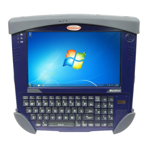
Page 20: Front View
Front View 1. Status Indicators 2. Speakers 3. Touch Screen / Display 4. Microphone 5. Power Button 6. Biometric Mouse Rear View Extended battery is not installed in image shown below. 1. Magnetic Stripe Card Reader Add-on Cover 2. Camera 3. -
Page 21: Bottom View
2. Docking Connector (for use in desktop and vehicle mounted docks) Right Side View The components are on the right edge of the Marathon when viewed from the front. 1. USB Port Cover 2. Reset Button 3. Two USB 2.0 Host Ports Left Side View The components are on the left edge of the Marathon when viewed from the front. -
Page 22: Leds And Indicators
LEDs and Indicators Power Button The power button is located in the upper right of the Marathon. The power button is backlit as follows: • Off when Marathon is Off. • Solid blue when the Marathon is On. • Flashes blue when the Marathon is in Standby Mode. -
Page 23: About The Battery
Charge or Recharge the Main Battery Note: A new Marathon must be connected to an external power source to charge the internal main battery before first use. The Marathon contains an internal Lithium Ion battery that, once fully charged, powers the Marathon for a minimum of 3 hours and 30 minutes (when the unit is not mounted in a powered dock or connected to an AC/DC adapter or extended bat- tery). -
Page 24: Tapping The Touch Screen With A Stylus
Tapping the Touch Screen with a Stylus Note: Always use the point of the stylus for tapping or making strokes on the touch screen. Never use an actual pen, pencil, or sharp/abrasive object to write on the touch screen. Hold the stylus as if it were a pen or pencil. Touch an element on the screen with the tip of the stylus then remove the stylus from the screen. -
Page 25: Attaching The Hand Strap
• Screws, strap attaching The hand strap is designed to be used with the Marathon with or without an extended battery attached. The hand strap is designed so the Marathon can be mounted in the desktop dock or the vehicle dock without removing the hand strap. -
Page 26: Attaching The Shoulder Strap
Attaching the Shoulder Strap The shoulder strap is designed to be used with the Marathon with or without an extended battery attached. The shoulder strap is designed so the Marathon can be mounted in the desktop dock or the vehicle dock without removing the shoulder strap. -
Page 27: Connecting Usb Devices
3. Plug the 3-prong end of the cordset into a grounded electrical supply receptacle (AC mains). 4. The LED on the AC adapter illuminates. 5. Open the port cover on the left side of the Marathon. When the power connector is not used, keep the port cover door closed. -
Page 28: Connecting An Audio Device
Connecting an Audio Device The Marathon provides an external headset connection via an audio jack connector under the left-side port cover. When the audio port is not in use, keep the port cover door closed. 1. Open the left-side port cover. -
Page 29: Connecting Bluetooth Devices
When using the keyboard, some keys have multiple functions. The primary alpha or numeric character is printed on the key. Bar Code Data Entry The Marathon supports an accessory imager module for bar code label reading, as well as optional equipment such as a wireless Bluetooth bar code scanner and a tethered USB scanner. -
Page 30: Magnetic Card Data Entry
• The cursor begins to flash in the field. • The Marathon is ready to accept data from either the keyboard, the accessory imager, a wireless Bluetooth device or a device connected to a serial port on a powered dock. -
Page 31: Chapter 3 - Hardware Configuration
AC/DC adapter connected directly to the Marathon. The main battery remains concealed in the Marathon while charging. The main battery will also recharge when the Marathon is docked in a powered desktop dock or vehicle dock. With an attached fully charged extended battery, Marathon battery life is increased to 6 or 10 hours based on the extended battery selected. -
Page 32: Backup Battery
Reset Button Use with caution. The Reset button is on the right side (display facing up) of the Marathon. Press the Reset button in with the tip of the stylus and the Marathon immediately disconnects all power sources. The Marathon turns Off (uncontrolled shutdown). -
Page 33: External Connectors
The Marathon power supply connector accepts DC input voltage at 19 Volts. Antenna Signal Pathway The external GPS and WWAN antenna signal pathways are located on the bottom of the Marathon. The antenna signals originate from the external GPS and WWAN antenna connectors on the vehicle dock. No physical antenna connects directly to these ports on the Marathon. -
Page 34: Keyboard Help
• Windows logon can be performed with a fingerprint scan as opposed to the traditional user name and password. You must create a Windows user account with a password, then shutdown and restart the Marathon before you can add fingerprint security to that user account. After rebooting, create fingerprint security, then shutdown and restart the Marathon to save the password in the registry. -
Page 35: Fingerprint Reader / Biometric Mouse
Fingerprint Reader / Biometric Mouse The Fingerprint Reader / Biometric Mouse SDK is available from the AuthenTec Developer Community web site. Click here to access the AuthenTec Developer Community web sites SDK link. Navigation By default, the biometric mouse is enabled for cursor navigation. Sliding a finger over the biometric mouse moves the cur- sor in the same direction the finger moves. -
Page 36: Touch Screen
Pre-requisite: The Marathon is in the Dock, and a second monitor is attached to the dock. The Marathon display driver has been setup to extend the Marathon display to the second monitor. Use a connected USB mouse to select items on the displays. The mouse can be connected to the Marathon or the desktop dock. -
Page 37: The Display
The Display The Marathon display is capable of supporting WVGA graphics modes (800x480). The display covering is designed to resist stains. The touch screen allows signature capture and touch input. A display optimized for outdoor viewing is available. The touch screen is a Resistive Panel with a scratch resistant finish that can detect touches by a stylus, and translate them into computer commands. - Page 38 3 - 8...
-
Page 39: Chapter 4 - Software Configuration
Introduction Like any personal computer, there are many aspects to the setup and configuration of the Marathon. Much of the setup and configuration of the Marathon is dependent upon the optional features (both hardware and software) installed on the computer. -
Page 40: Software Loaded On Drive C
This is a standard Microsoft Windows control panel applet. On the Settings tab, two displays are supported. By default, dis- play #1 is the Marathon's built in WVGA display. Display #2 is an external display connected to the VGA port on the Mara- thon desktop dock. -
Page 41: Power Options Panel
User Accounts Panel Note: The following applies to a Marathon that is not part of a domain. When the Marathon is part of a domain, the user is prompted for credentials at Windows startup or log on. -
Page 42: Network Configuration
When the GPS module is factory installed in the Marathon, based on the current Marathon configuration the GPS module will use COM 5 on the Marathon to retrieve latitude (the location north or south of the equator in degrees) and longitude (the angular distance from the Prime Meridian in degrees). -
Page 43: Chapter 5 - Using Peripherals / Accessories
4. Line up the charging pins on the extended battery with the charging pins in the Marathon extended battery connector bay. 5. Connect the extended battery to the Marathon using the captive screws in the extended battery. - Page 44 The Marathon is ready for use. Remove the extended battery from the Marathon when preparing to recharge the extended battery in a powered desktop dock or in a Marathon battery charger. Up to four extended batteries can be charged simultaneously in the battery charger.
-
Page 45: Installing A Sim Card
1. Turn the Marathon off. 2. Place the Marathon face down on a stable surface. 3. Remove the 4 mounting screws securing the battery cover to the Marathon and remove the battery cover. Put the screws aside in a safe place. -
Page 46: Replacing The Main Battery
4. Lift the battery using the pull strap. 5. Hold the battery out of the way and carefully separate the Marathon plug (on the right) from the plug cabled to the main battery. Do not bend the pins. - Page 47 The Marathon is ready for use. Li-Ion Battery When disposing of the lithium-ion battery, the following precautions should be observed: The battery should be disposed of properly. The battery should not be disassembled or crushed. The battery should not be heated above 212°F (100°C) or incinerated.
-
Page 48: Bar Code Readers
The Marathon can use the following external bar code readers: • Tethered hand-held scanners are tethered to a USB port on the Marathon or a serial port on the Marathon dock and are configured by scanning the engine-specific bar codes in the scanner manufacturer's programming guide. The manufacturer's guides are usually shipped with the bar code reader. -
Page 49: Loading An Operating System On The Marathon
(page 14-1) to get the latest updates before performing the procedures that follow. The Recovery DVD is a method to restore the software on your Marathon to the same state it had when it was shipped from the factory. When the Recovery DVD is used on your Marathon, it destroys any information on your hard disk so make sure that any information on the hard disk that needs to be preserved is backed up before using the Recovery DVD. - Page 50 5 - 8...
-
Page 51: Introduction
Change settings for all users is tapped before changing the privilege level. It is important that all dates are correct on the Marathon and host computers when using any type of certificate. Cer- tificates are date sensitive and if the date is not correct authentication will fail. - Page 52 2. Change the value for the Supplicant property value to Third Party. 3. Tap Commit. 4. Restart the Marathon. The Laird Connection Manager passes control to Wireless Zero Config and the WZC Wireless Information control panel. Using the options in the Wireless Zero Config panels, set up radio and security settings. There may be a slight delay before the Wireless Zero Config icon indicates the status of the connection.
- Page 53 Status Start > All Programs > Laird > Laird Connection Manager > Status tab This screen provides information on the radio: • The status of the radio card: ○ Down - The radio is not recognized by the LCM. ○ Disabled - The radio is disabled. ○...
- Page 54 Configuration Start > All Programs > Laird > Laird Connection Manager > Configuration tab Wi-Fi Checkbox When checked, the Wi-Fi radio is enabled. Wi-Fi is enabled by default. Manage Profiles Tap this button to edit an existing profile, create a new profile, delete a profile, edit global parameters or login as an admin.
- Page 55 Delete Tap Delete to delete the currently highlighted profile in the Profile: drop down box. Tap Yes to delete the profile or No to exit without deleting. Note: You cannot delete the currently active profile. Parameters The items on the Parameters tab only affect the selected profile. When a property is selected from the list either a text box or a pull down list is displayed to the right for the entry of a value for that property.
- Page 56 Globals Items on the Globals tab affect all profiles. When a property is selected from the list either a text box or a pull down list is displayed to the right for the entry of a value for that property. After changing the desired properties, tap the Commit button. Default Property Explanation...
- Page 57 Default Property Explanation Value Aggressive When set to On and the current connection to an AP weakens, the radio ag- Scan gressively scans for available APs. Aggressive scanning works with standard scanning (set through Roam Trig- ger, Roam Delta and Roam Period). Aggressive scanning should be set to On unless there is significant co-channel interference due to overlapping APs on the same channel.
- Page 58 Default Property Explanation Value Tray Icon The tray icon is not displayed when the Marathon is running a Windows Em- bedded Standard 2009, Windows Embedded Standard 7 or Windows 7 Pro- fessional operating system. Admin SUMMIT A string of up to 64 alphanumeric characters that must be entered when the...
- Page 59 Admin Login To login to Administrator mode, enter the admin password and tap the Login button. Once logged in, the button label changes to Logout. The admin is automatically logged out when the LCM is exited. Enter the Admin password (the default password is SUMMIT and is case sensitive) and tap OK. If the pass- word is incorrect, an error message is displayed.
- Page 60 Diagnostics Start > All Programs > Laird > Laird Configuration Manager > Diagnostics tab The Diagnostics screen can be used for troubleshooting network traffic and radio connectivity issues. This screen displays the status of the Wi-Fi radio. • About – Use this button to view the version of the LCM and other software information. •...
- Page 61 The Ping screen is used to ping another device. IP - Displays the IP address of the Marathon Use the text box at the upper right to enter the IP address to ping. Information on the selected function is dis- played in the output box in the center of the screen.
-
Page 62: Sign-On Vs. Stored Credentials
The user must enter the Username and Password at that time to authenticate. • When using LCM with the Marathon, there is an option on the Global tab to use the Windows user name and password to log on instead of any username and password stored in the profile. - Page 63 To Use Stored Credentials 1. After completing the other entries in the profile, scroll down for the credentials entry. 2. Enter the Username and Password. 3. Click the Commit button. 4. For LEAP and WPA/LEAP, configuration is complete. 5. Importing the CA certificate into the Windows certificate store is optional. 6.
-
Page 64: Windows Certificate Store Vs. Certs Path
Windows Certificate Store vs. Certs Path Note: It is important that all dates are correct on the Marathon and host computers when using any type of certificate. Certificates are date sensitive and if the date is not correct authentication will fail. - Page 65 User Certificates EAP-TLS authentication requires a user certificate. The user certificate must be stored in the Windows certificate store. • To generate the user certificate, see Generating a User Certificate (page 6-72). • To import the user certificate into the Windows certificate store, see Installing a User Certificate (page 6-76).
- Page 66 Root CA Certificates Root CA certificates are required for EAP/TLS, PEAP/GTC and PEAP/MSCHAP. Two options are offered for storing these certificates. They may be imported into the Windows certificate store or copied into the Certs Path directory. Certs Path 1. See Generating a Root CA Certificate (page 6-69) and follow the instructions to download the Root Certificate to a PC.
-
Page 67: Configuring The Profile
Configuring the Profile Use the instructions in this section to complete the entries on the Profile tab according to the type of wireless security used by your network. The instructions that follow are the minimum required to successfully connect to a network. Your system may require more parameters than are listed in these instructions. - Page 68 No Security To connect to a wireless network with no security, make sure the following profile options are used. 1. Enter the SSID of the Access Point assigned to this profile 2. Set Auth Type to Open 3. Set WPA to None 4.
- Page 69 To connect using WEP, make sure the following profile options are used. 1. Enter the SSID of the Access Point assigned to this profile 2. Set Auth Type to Open 3. Set WPA to None 4. Set Encryption to WEP 5.
- Page 70 LEAP To use LEAP (without WPA, also called WEP-LEAP), make sure the following profile options are used. 1. Enter the SSID of the Access Point assigned to this profile 2. Set Auth Type as follows: • If the Cisco/CCX certified AP is configured for open authentication, set Auth Type to Open. •...
- Page 71 PEAP/MSCHAP To use PEAP/MSCHAP, make sure the following profile options are used. 1. Enter the SSID of the Access Point assigned to this profile 2. Set Auth Type to Open 3. Set WPA as follows: • Select WPA/WPA2 to use either TKIP/AES or AES-CCMP •...
- Page 72 Enter the password. Leave the CA Certificate File Name blank for now. Click OK then click Commit. Ensure the correct Active profile is selected on the Configuration tab. Windows Certificate Store vs. Certs Path (page 6-14) for more information on certificate storage. Once successfully authenticated, import the CA certificate into the Windows certificate store.
- Page 73 PEAP/GTC To use PEAP/GTC, make sure the following profile options are used. 1. Enter the SSID of the Access Point assigned to this profile 2. Set Auth Type to Open 3. Set WPA as follows: • Select WPA/WPA2 to use either TKIP/AES or AES-CCMP •...
- Page 74 Leave the CA Certificate File Name blank for now. Click OK then click Commit. Ensure the correct Active Profile is selected on the Configuration tab. Windows Certificate Store vs. Certs Path (page 6-14) for more information on certificate storage. Once successfully authenticated, import the CA certificate into the Windows certificate store. Return to the Credentials screen and check the Validate server checkbox.
- Page 75 WPA/LEAP To use WPA/LEAP, make sure the following profile options are used. 1. Enter the SSID of the Access Point assigned to this profile 2. Set Auth Type as follows: • If the Cisco/CCX certified AP is configured for open authentication, set Auth Type to Open. •...
- Page 76 Click the Commit button. Ensure the correct Active Profile is selected on the Configuration tab and restart. The Status tab shows the device is connected. 6 - 26...
- Page 77 RADIUS server. The RADIUS server must have auto provisioning enabled to send the PAC provisioning credentials to the Marathon. For automatic PAC provisioning, once a username/password is authenticated, the PAC information is stored on the Marathon.
- Page 78 To use Sign-On credentials: • Do not enter a User and Password as the user will be prompted for the Username and Password when connecting to the network. To use Stored Credentials: • Enter the Domain\Username (if the Domain is required), otherwise enter the Username. •...
- Page 79 EAP-TLS To use EAP-TLS, make sure the following profile options are used. 1. Enter the SSID of the Access Point assigned to this profile 2. Set Auth Type to Open 3. Set WPA as follows: • Select WPA/WPA2 to use either TKIP/AES or AES-CCMP •...
- Page 80 2. Enter the certificate filename in the CA Cert text box. 3. Click Commit. The Marathon should be authenticating the server certificate and using EAP-TLS for the user authentication. Ensure the correct Active Profile is selected on the Configuration tab and restart. The Status tab shows the device is connected.
- Page 81 EAP-TTLS To use EAP-TTLS, make sure the following profile options are used. 1. Enter the SSID of the Access Point assigned to this profile 2. Set Auth Type to Open 3. Set WPA as follows: • Select WPA/WPA2 to use either TKIP/AES or AES-CCMP •...
- Page 82 Enter the password. Leave the CA Certificate File Name blank for now. Click OK then click Commit. Ensure the correct Active profile is selected on the Configuration tab. Windows Certificate Store vs. Certs Path (page 6-14) for more information on certificate storage. Once successfully authenticated, import the CA certificate into the Windows certificate store.
- Page 83 PEAP-TLS To use PEAP-TLS, make sure the following profile options are used. 1. Enter the SSID of the Access Point assigned to this profile 2. Set Auth Type to Open 3. Set WPA as follows: • Select WPA/WPA2 to use either TKIP/AES or AES-CCMP •...
- Page 84 2. Enter the certificate filename in the CA Cert text box. 3. Click Commit. The Marathon should be authenticating the server certificate and using EAP-TLS for the user authentication. Ensure the correct Active Profile is selected on the Configuration tab and restart. The Status tab shows the device is connected.
- Page 85 WPA PSK To connect using WPA/PSK, make sure the following profile options are used: 1. Enter the SSID of the Access Point assigned to this profile 2. Set Auth Type to Open 3. Set WPA as follows: • Select WPA/WPA2 to use either TKIP/AES or AES-CCMP •...
-
Page 86: Summit Wireless Network Configuration
(page 6-37). Important Notes It is important that all dates are correct on the Marathon and host computers when using any type of certificate. Certificates are date sensitive and if the date is not correct authentication will fail. Verify and adjust the date using the Date and Time control panel. -
Page 87: Summit Client Utility
• The Windows Zero Config utility is not active. • The Tray Icon setting is On. • Tray icon is not shown when the Marathon is running Windows 7 or Windows Embedded Standard. Click the icon to launch the SCU. -
Page 88: Wireless Zero Config Utility
• You can use either the Wireless Zero Configuration Utility or the Summit Client Utility to connect to your network. Honeywell recommends using the Summit Client Utility to connect to your network. The Wireless Zero Configuration Utility cannot control the complete set of security features of the radio. -
Page 89: Main Tab
Main Tab Setting Default Admin Login SUMMIT Radio Enabled Active Config/Profile ThirdPartyConfig Regulatory Domain Varies by location The Main tab displays information about the wireless client device including: • SCU (Summit Client Utility) version. • Driver version. • Radio Type (ABGN is an 802.11 a/b/g/n radio). •... -
Page 90: Admin Login
Admin Login To login to Administrator mode, tap the Admin Login button. Once logged in, the button label changes to Admin Logout. The admin is automatically logged out when the SCU is exited. The Admin can either tap the Admin Logout button, or the OK button to logout. Enter the Admin password (the default password is SUMMIT and is case sensitive) and tap OK. -
Page 91: Profile Tab
Profile Tab Note: Tap the Commit button to save changes before leaving this panel or the SCU. If the panel is exited before tapping the Commit button, changes are not saved! Setting Default Profile Default SSID Blank Client Name Blank Power Save Fast Tx Power... - Page 92 Buttons Button Function Commit Saves the profile settings made on this screen. Settings are saved in the profile. Credentials Allows entry of a username and password, certificate names, and other information required to au- thenticate with the access point. The information required depends on the EAP type. Delete Deletes the profile.
- Page 93 It is important the Radio Mode setting correspond to the Access Point to which the device is to connect. For example, if this setting is set to G rates only, the Marathon may only connect to Access Points set for G rates and not those set for B and G rates.
-
Page 94: Status Tab
Status Tab This screen provides information on the radio: • The profile being used. • The status of the radio card (down, associated, authenticated, etc.). • Client information including device name, IP address and MAC address. • Information about the Access Point (AP) maintaining the connection to the network including AP name, IP address and MAC address. -
Page 95: Diags Tab
Diags Tab The Diags screen can be used for troubleshooting network traffic and radio connectivity issues. • (Re)connect – Use this button to apply (or reapply) the current profile and attempt to associate or authenticate to the wireless LAN. All activity is logged in the Diagnostic Output box on the lower part of the screen. •... -
Page 96: Global Tab
Global Tab The settings on this panel can only be changed when an Admin is logged in with a password. The current values for the set- tings can be viewed by the general user without requiring a password. Note: Tap the Commit button to save changes. If the panel is exited before tapping the Commit button, changes are not saved! Setting Default... - Page 97 Custom Option Honeywell does not support the Custom option. The value is displayed as “Custom” when the operating system regis- try has been edited to change the Summit setting to a value that is not available from the settings drop down list.
- Page 98 Setting Default Function Ad Hoc Channel Use this setting when the Radio Mode profile is set to Ad Hoc. Specifies the channel to be used for an Ad Hoc connection to another client de- vice. If a channel is selected that is not supported by the by the radio, the default value is used.
- Page 99 Tray Icon Determines if the Summit icon is displayed in the System tray. Options are: On, Off Note: The tray icon is not displayed when the Marathon is running a Windows Embedded Standard or Windows 7 Professional operating system. Hide Password...
- Page 100 Logon Options There are two options available, a single signon which uses the Windows username and password as the credentials for 802.1x authentication and pre-logon which uses saved credentials for 802.1x authentication before Windows logon. If either option is enabled, the credentials entered here take precedence over any credentials entered on the Profile tab.
- Page 101 Once this option is enabled, the Authentication delay and Association timeout values can be adjusted as nec- essary. Both values are specified in milliseconds (ms). The default authentication delay is 5000 ms and the valid range is 0 - 600,000 ms. The default association timeout is 10,000 ms and the valid range is 10,000 to 600,000 ms.
-
Page 102: Sign-On Vs. Stored Credentials
Notification bar to display the login screen. Enter user name and password and click OK to close the window. This procedure will need to be followed each time the Marathon returns from, for example: •... -
Page 103: Using A Windows User Name And Password
3. For EAP-TLS, import the CA certificate into the Windows certificate store. Also import the User Certificate into the Windows certificate store. 4. Access the Credentials screen again. Make sure the Validate server and Use MS store checkboxes are checked. 5. -
Page 104: Windows Certificate Store Vs. Certs Path
Windows Certificate Store vs. Certs Path Note: It is important that all dates are correct on the Marathon and host computers when using any type of certificate. Certificates are date sensitive and if the date is not correct authentication will fail. -
Page 105: Configuring The Profile
6. Uncheck the Use full trusted store checkbox. 7. Select the desired certificate and click the Select button to return the selected certificate to the CA Cert text- box. 8. Click OK to exit the Credentials screen and then Commit to save the profile changes. Configuring the Profile Use the instructions in this section to complete the entries on the Profile tab according to the type of wireless security used by your network. - Page 106 No Security To connect to a wireless network with no security, make sure the following profile options are used. 1. Enter the SSID of the Access Point assigned to this profile. 2. Set EAP Type to None. 3. Set Encryption to None. 4.
- Page 107 To connect using WEP, make sure the following profile options are used. 1. Enter the SSID of the Access Point assigned to this profile. 2. Set EAP Type to None. 3. Set Encryption to WEP or Manual WEP (depending on SCU version). 4.
- Page 108 LEAP To use LEAP (without WPA), make sure the following profile options are used. 1. Enter the SSID of the Access Point assigned to this profile. 2. Set EAP Type to LEAP. 3. Set Encryption to WEP EAP or Auto WEP (depending on SCU version). 4.
- Page 109 PEAP/MSCHAP To use PEAP/MSCHAP, make sure the following profile options are used. 1. Enter the SSID of the Access Point assigned to this profile. 2. Set EAP Type to PEAP-MSCHAP. 3. Set Encryption to WPA TKIP. 4. Set Auth Type to Open. 5.
- Page 110 9. Enter the Domain\Username (if the Domain is required), otherwise enter the User name. 10. Enter the password. 11. Leave the CA Certificate File Name blank for now. 12. Click OK then click Commit. Ensure the correct Active profile is selected on the Main tab. 13.
- Page 111 PEAP/GTC To use PEAP/GTC, make sure the following profile options are used. 1. Enter the SSID of the Access Point assigned to this profile. 2. Set EAP Type to PEAP-GTC. 3. Set Encryption to WPA TKIP. 4. Set Auth Type to Open. 5.
- Page 112 9. Enter the Domain\Username (if the Domain is required), otherwise enter the Username. 10. Enter the password. 11. Leave the CA Certificate File Name blank for now. 12. Click OK then click Commit. Ensure the correct Active Profile is selected on the Main tab. 13.
- Page 113 WPA/LEAP To use WPA/LEAP, make sure the following profile options are used. 1. Enter the SSID of the Access Point assigned to this profile. 2. Set EAP Type to LEAP. 3. Set Encryption to WPA TKIP. 4. Set Auth Type as follows: •...
- Page 114 RADIUS server. The RADIUS server must have auto provisioning enabled to send the PAC provisioning credentials to the Marathon. For Automatic PAC provisioning, once a username/password is authenticated, the PAC information is stored on the Marathon.
- Page 115 1. Click on the Credentials button. 2. To use Stored Credentials, click on the Credentials button. No entries are necessary for Sign-On Credentials with automatic PAC provisioning as the user will be prompted for the Username and Password when connecting to the network.
- Page 116 EAP-TLS To use EAP-TLS, make sure the following profile options are used. 1. Enter the SSID of the Access Point assigned to this profile. 2. Set EAP Type to EAP-TLS. 3. Set Encryption to WPA TKIP. 4. Set Auth Type to Open. 5.
- Page 117 • Leave the Use MS store box unchecked. • Enter the certificate filename in the CA Cert textbox. 17. Click OK then click Commit. The Marathon should be authenticating the server certificate and using EAP-TLS for the user authentication. 18. Ensure the correct Active Profile is selected on the Main tab and restart. The SCU Main tab shows the device is associated after the radio connects to the network.
- Page 118 WPA PSK To connect using WPA/PSK, make sure the following profile options are used: 1. Enter the SSID of the Access Point assigned to this profile. 2. Set EAP Type to None. 3. Set Encryption to WPA PSK or WPA2 PSK. 4.
-
Page 119: Certificates
Note: Refer to the Security Primer (available at www.honeywellaidc.com) to prepare the Authentication Server and Access Point for communication. Note: It is important that all dates are correct on the Marathon and host computers when using any type of certificate. Certificates are date sensitive and if the date is not correct authentication will fail. - Page 120 5. Click the Download a CA certificate, certificate chain or CRL link. 6. Make sure the correct root CA certificate is selected in the list box. 7. Click the DER button. 8. To download the CA certificate, click on the Download CA certificate link. 6 - 70...
-
Page 121: Installing A Root Ca Certificate
4. In the left pane, right click Trusted Root Certificate Authorities and select All Tasks > Import. 5. The Certificate Import Wizard starts. 6. Tap Next and use the Browse... button to locate the Root certificate copied to the Marathon then tap Open. 7. The certificate filename and path are displayed. Tap Next. -
Page 122: Generating A User Certificate
Generating a User Certificate The easiest way to get the user certificate is to use the browser on the Marathon or a PC to navigate to the Certificate Authority. To request the user certificate, open a browser to http://<CA IP address>/certserv. - Page 123 1. Sign into the CA with the username and password of the person who will be logging into the mobile device. 2. This process saves a user certificate file. There is no separate private key file as used on Windows CE devices. 3.
- Page 124 6. The User Certificate is issued. 7. Install the user certificate on the requesting computer by clicking the Install this certificate link. 8. If the requesting computer is the Marathon, then the process is finished. otherwise, export the certificate as described below.
-
Page 125: Exporting A User Certificate
Exporting a User Certificate 1. Select Tools > Internet Options > Content and click the Certificates button. 2. Make sure the Personal tab is selected. Highlight the certificate and click the Export button. 3. The Certificate Export Wizard is started 4. -
Page 126: Installing A User Certificate
11. Install the User certificate (see Installing a User Certificate). Installing a User Certificate 1. After generating and exporting the user certificate, copy it from the PC to the Marathon. Copy the certificate to a loca- tion on the Marathon. - Page 127 11. You are prompted for the password that was assigned when the certificate was exported. Note: It is not necessary to select either of the check boxes displayed above. Note: For Windows 7 Professional, there is a third check box: Include all extended properties. This check box should remain checked.
- Page 128 6 - 78...
-
Page 129: Chapter 7 - Bluetooth Configuration
Use the Bluetooth Device Wizard in the Microsoft Windows Control Panel to discover and manage paired Bluetooth devices. The Bluetooth client in the Marathon is supported by the following operating systems installed on the Marathon. Procedure differences are marked with the operating system icon as shown below:... -
Page 130: Devices Tab
Devices Tab The Devices tab displays any previously discovered Bluetooth devices. If there are no Bluetooth devices shown or if the desired device is not shown, use the Add Bluetooth Device Wizard to dis- cover Bluetooth devices. Click the Add button to start the wizard. 7 - 2... - Page 131 The wizard cannot be started until the checkbox indicating the device is set up and ready to be found is checked. If any Bluetooth devices are discovered, they are displayed on the next screen. 7 - 3...
-
Page 132: Options Tab
Select the desired Bluetooth device and click Next. Select the appropriate passkey option. The Bluetooth device is ready to use. Options Tab This tab contains various Bluetooth connection options. More information can be found using Help and Support on the Win- dows Start menu. -
Page 133: Com Ports Tab
COM Ports Tab This tab displays the COM ports used by Bluetooth devices, such as the Bluetooth printer illustrated. More information can be found using Help and Support on the Windows Start menu. 7 - 5... -
Page 134: Hardware Tab
Hardware Tab This tab displays hardware information for Bluetooth. More information can be found using Help and Support on the Win- dows Start menu. 7 - 6... -
Page 135: Chapter 8 - Oneclick Internet Wireless Configuration
If this delay is acceptable to you, standby may be enabled. OneClick Internet is supported by the following operating systems installed on a Marathon with a WWAN radio card. Procedure differences are marked with the operating system icon as shown below:... -
Page 136: Preparing For Initial Use On The Marathon
Activation This step is only necessary for Verizon. You need the IMEI number for the Marathon when you contact Verizon prior to activating service on the Marathon. The IMEI number can be found on the Settings > Info tab, see Info Tab (page 8-13). - Page 137 4. Tap Next to complete the activation. Once the activation is completed, OneClick Internet may be minimized to the tray. To verify your settings, tap on the OneClick Internet icon in the system tray. 1. Tap Settings. 2. Tap the Network tab. 8 - 3...
- Page 138 3. The Network tab contains the settings including the telephone number from the provider, in this case Verizon. 8 - 4...
-
Page 139: Using Oneclick Internet
Using OneClick Internet If OneClick Internet is inactive, double tap the desktop icon to load it. When OneClick Internet is active but minimized to the system tray, tap the OneClick Internet status icon in the system tray to maximize it. Using Connection Manager 1. -
Page 140: Menu Buttons
Update Button One Click Internet provides a built-in online update functionality that allows for an automatic update of OneClick Internet application, device drivers, and APN database. Honeywell DOES NOT recommend using the Update button feature. Contact Customer Support (page 14-1) for information on upgrading to another version of OneClick Internet. -
Page 141: Settings Button
Settings Button Use the following Settings tabs to view, edit and update OneClick Internet settings: • Profile • Network • History • PIN • Info • Firmware • General Profile Tab Create a connection profile to store connection information. Once a profile has been created, its name appears in the drop down Profiles list, which replaces the Profile Name textbox in the illustration above. - Page 142 Buttons Button Function Create a new profile. When this option is selected, the Profile Name is in a text box. Enter a name for the profile as well as other connection specific configuration. When finished, tap the Save button to save the new profile. Edit a current profile.
- Page 143 Network Tab The appearance of the network tab depends on the type of firmware selected. Network with SIM Card Select Connection Select connection and tap Apply. A “Network changed successfully” message is displayed. Setting Function Select automatically Selects the best suited network automatically Use GPRS/EDGE only Use only GPRS/EDGE for a connection Use UMTS/HSPA only...
- Page 144 This item is useful when traveling. Automatic mode selects the preferred network of your network operator. If enabled, Network Selection displays a list of network options: • Automatic Selection • Retrieving Networks... The currently registered network is marked. CDMA Network Information on the CDMA network is displayed.
- Page 145 History Tab The History panel shows the data volume transferred in a specified time frame. Select the From and To dates to see the data volume sent/received in the specified period. Tap Reset to reset the counter. 8 - 11...
- Page 146 PIN Tab You can Activate/Deactivate the PIN or Change the PIN. Activate/Deactivate PIN This panel is only displayed when a firmware is loaded that requires a SIM card (such as AT&T or T-Mobile). By default, you have to enter the PIN each time you start WebToGo OneClick Internet using a modem card. Deactivate the PIN to avoid entering the PIN each time.
- Page 147 Info Tab This tab displays SIM card, modem and system Information. There are no editable settings on this tab. 8 - 13...
- Page 148 Firmware Tab OneClick Internet selects the correct Firmware matching your operator automatically, if a special firmware for your operator is available and a SIM card is inserted. If no specific firmware for your operator is available, generic firmware is selected. After a firmware has been selected, it appears as the Current Profile. You can manually load your desired firmware.
- Page 149 Marathon and logs in. Connect Automatically When selected OneClick Internet automatically connects on start-up. Reconnect Automatically When selected OneClick Internet reconnects automatically when the Marathon returns from standby or hibernate. Allow roaming When selected OneClick Internet allows connections in foreign networks.
- Page 150 Application Tab Use the Application tab to specify any application to launch automatically once the Internet connection is established. Use the Browse button to locate the desired application. 8 - 16...
-
Page 151: Sms
The SMS Center window is split into menu bar, folder view, folder content and preview win- dow. Folders Button Manage SMS folders. By using this menu, you may change the folder structure of the SMS Center: Button Function New Folder Creates a new folder, name has to be unique Rename Renames an existing folder... - Page 152 New Message Button Create new SMS/MMS message. The New Message window is used to enter the SMS text. You may also enter texts by copy and paste from other applications. The status bar at the lower right corner indicates the length of the SMS for your convenience: the first number tells you how many parts the SMS consists of (one part has max.
- Page 153 Addresses Button Manage phone book contacts on SIM and in Email client. Clicking this button opens the address book. You may add new contacts to your personal address book or you may change existing addresses, delete addresses or exchange them with your SIM card and your Email client application, or export the data set. Buttons Function New Contact...
-
Page 154: Web Browser Button
After Latitude and Longitude Data are displayed, the user can tap Clipboard and the latitude and longitude data are copied to the Marathon clipboard cache. The data can be pasted into an email, document or other electronic media. Installing or Upgrading OneClick Internet Note: You must use the Honeywell supplied version of OneClick Internet. - Page 155 2. Next, select the application language. By default, the language of the OS is used (if available). 3. Review and accept the license agreement. Click Accept, if you agree. Otherwise click Reject to cancel installation. 4. Next the installer asks for the installation directory. Use the Browse button to specify a location other than the default. 8 - 21...
- Page 156 5. Installation process is indicated on screen. When completed. click the Finish button to exit the installer. 6. Start OneClick Internet from the Windows Program Menu or double tap the desktop icon. 8 - 22...
-
Page 157: Chapter 9 - Keymaps
KeyMaps Introduction Alt, Ctl, Fn, Num Lck and Shift are sticky keys: • Press once, illuminates blue and stays sticky for next keypress. • Press and hold for 1.5 seconds, illuminates blue and stays sticky until the same key is pressed again. •... - Page 158 To get this key/function Press these keys in this order... Shift Shift Shift Shift Shift Shift Shift Shift Shift Shift Shift Shift Shift Shift Shift Shift Shift Shift Shift Shift 9 - 2...
- Page 159 To get this key/function Press these keys in this order... Shift Shift Shift Shift Shift Shift Num Lck ON Num Lck ON Num Lck ON Num Lck ON Num Lck ON Num Lck ON Num Lck ON Num Lck ON Num Lck ON Num Lck ON .
- Page 160 9 - 4...
-
Page 161: Chapter 10 - Battery Charger
This device cannot charge/recharge coin cell batteries sealed inside the mobile device, if any. This chapter is intended to familiarize the user with the safety and operating instructions necessary to use the Marathon Battery Charger (Model FX1385CHARGER, FX1386CHARGER) to charge rechargeable lithium-ion batteries (42Whr FX1381BATTERY and 62Whr FX1382BATTERY) . -
Page 162: Cautions And Warnings
• Do not store the Li-Ion battery pack in direct sunlight or anywhere the battery pack cannot cool down. • If the Li-Ion battery pack is hot after removal from the Marathon, allow it to cool at room temperature or in a cool air stream before placing it in the charger. -
Page 163: Battery Charger Top View
The mounting holes require #10 / 4mm screws/washers or bolts/nuts (not supplied by Honeywell). Extended Battery Back View 1. Captive Screw 2. Rubber Foot 3. Battery Charging Terminals The Marathon 42Whr Extended or 62Whr Extended batteries are physically identical except the 62Whr battery is thicker than the 42Whr battery. 10 - 3... -
Page 164: Installation
Customer Support (page 14-1) if there is no AC cable. The battery charger power supply can be used with the Marathon battery charger and with the Marathon desktop dock. 1. AC Input Connector (US only) 2. Battery Charger end (DC Output Connector) •... -
Page 165: Inserting A Battery Into The Charging Pocket
While charging, the charger and battery pack will generate enough heat to feel warm. This is normal and does not indicate a problem. Inserting a Battery into the Charging Pocket Caution! It is important that battery packs are inserted into the charging pocket correctly. Inserting the battery incorrectly could result in damage to the battery pack or the charger. -
Page 166: Interpreting The Charging Pocket Leds
Interpreting the Charging Pocket LEDs The status of the charge operation is indicated by the color of the LED for each charging pocket. YELLOW - on any charge pocket Continuous yellow means the battery pack is charging. YELLOW FLASHING - on any charge pocket Standby, battery pack temperature is not within charging range. -
Page 167: Battery Charger Help
Battery Charger Help The following is intended as an aid in determining whether the battery pack or the charger may be malfunctioning: Issue Cause Solution Battery pack does not Different manufacturer's battery Check if the battery pack has part number fit in charging pocket. -
Page 168: Charger Cleaning, Storage And Service
Issue Cause Solution Solid YELLOW / The battery pack is too hot or too Remove battery pack from the charging pocket and allow AMBER LED when cold to charge. it to adjust to room temperature. battery pack is Note: If the battery pack is left in the charging pocket, it will cool down or warm to a temperature upon which inserted in the the charger will begin the charge cycle. -
Page 169: Chapter 11 - Desktop Dock And Powered Vehicle-Mount Dock
USB keyboard, USB mouse, USB tethered scanner, etc., to the dock for desktop use while the Marathon is docked. Using a wall AC adapter the desktop dock can also recharge either size of the extended Marathon battery in approximately 4 hours. -
Page 170: Preparing The Dock For Use
Note: Keep dirt and foreign objects out of the dock. Do not short circuit any of the charging terminals, as this action could result in injury or property damage. Honeywell recommends a stable, horizontal surface out of the way of: • inclement weather conditions, •... -
Page 171: Assemble/Attach The Ac Power Adapter
2. Dock end (DC Output Connector) 1. Connect the detachable cordset (1) provided by Honeywell (US only, all others must provide their own cable) to the external power supply (IEC 320 connector). 2. Plug cordset into appropriate, grounded, electrical supply receptacle (AC mains). -
Page 172: Connect Cables
An external serial monitor cable can be connected to this port. USB Ports The Marathon dock has four USB 2.0 ports, two on the front of the dock and two on the rear of the dock. USB ports on the dock support hot swapping. -
Page 173: Status Leds
Spare Battery Charging Bay LED Note: When the main battery in the Marathon is being charged using power from the dock, the battery icon on the front of the Marathon illuminates. -
Page 174: Docking And Undocking
Note: Do not "slam" or slide the Marathon sideways into the dock. Damage may result. To undock the Marathon, grasp it firmly at the side and lift it straight up and out of the dock. If the dock is not attached to a mounting surface, stabilize the dock with one hand while removing the Marathon from the dock with the other hand. -
Page 175: Desktop Dock Help
Desktop Dock Help Note: The following is intended as an aid in determining whether the extended battery or the dock spare battery charging bay may be malfunctioning. Issue Cause Solution Extended battery Different manufacturer's extended battery, Check if the battery pack is part number does not fit in spare or there is an object in the battery well. -
Page 176: Desktop Dock Maintenance
Use a clean soft cloth to wipe any dirt, moisture or grease from the Marathon, extended batteries, charging contacts (pins) and the dock. Do not use any liquid to clean the extended battery, Marathon, dock, or charging bays. Spray or dampen the cleaning cloth with liquids/sprays. If possible, clean only those areas which are soiled. -
Page 177: Powered Vehicle-Mounted Dock
The vehicle mounted assembly restrains the Marathon, recharges the main battery in the Marathon and isolates it from shock and vibration. Keypad data entries can be mixed with wireless bar code scanner data entries while the Marathon is in a powered vehicle dock. -
Page 178: Front View
Front View 11 - 10... -
Page 179: Back View
When the vehicle dock is receiving power from the vehicle, the Power LED illuminates blue, otherwise the LED is off. Note: When the main battery in the Marathon is being charged using power from the dock, the battery icon on the front of the Marathon illuminates. -
Page 180: Docking / Undocking
Place the Marathon in the Vehicle Dock Lower the Marathon into the docking bay until it is seated and then push it back into the dock. The release mechanisms will slide out of the way, and then spring forward, securing the Marathon in the vehicle dock. - Page 181 Step 4 - Place Marathon in the Vehicle Dock 1. Lower the Marathon into the docking bay until it is seated and then push it back into the dock. The release mecha- nisms will slide out of the way, and then spring forward, securing the Marathon in the vehicle dock.
-
Page 182: Vehicle 12-24 Vdc Power Connection
Note: Correct electrical polarity is required for safe and proper installation. Connect Vehicle 12-24 VDC Connection 1. The Marathon should not be in the vehicle mounted dock during the following procedure. 2. While observing the fuse requirements specified above, connect the power cable as close as possible to the actual battery terminals of the vehicle. - Page 183 3. Route the power cable the shortest way possible. The cable is rated for a maximum temperature of 75°C (167°F). When routing this cable it should be protected from physical damage and from surfaces that might exceed this tem- perature. 4.
-
Page 184: Connecting A Cigarette Lighter Power Adapter
2. Plug the barrel connector end of the cordset into the Marathon Power port. 3. When the Marathon is receiving power from the vehicle, the Battery Status LED at the upper left, next to the Mara- thon display, illuminates orange to indicate the Marathon battery is recharging. -
Page 185: Remote Antenna Installation Kit
Gigabit Ethernet connection. When a LAN connection is made via Ethernet cable, the appropriate LAN LED on the front of the dock is illuminated. A second LAN LED indicates LAN activity. Any USB client device can be connected to the Marathon in the vehicle dock using the 3 port adapter USB ends. Antenna Connectors Connect the antenna to the appropriately marked antenna port. - Page 186 11 - 18...
-
Page 187: Chapter 12 - Technical Specifications
Operating Systems Microsoft® Windows® Embedded Standard Microsoft® Windows® 7 Professional Microsoft® Windows® XP® Professional Marathon Environmental Specifications The Marathon will withstand the following environmental characteristics and has been tested in accordance with applicable sections of MIL-STD-810E. Feature Specification Operating Temperature -20°C to +48°C (-4°F to +118°F) Note: Without extended battery. -
Page 188: Marathon Display Specifications
Marathon Display Specifications Characteristic Specification Display Type 7.1" LCD with back light Resolution WVGA 800x480 Optimized for Indoor or Outdoor use Touch Analog Resistive 4-wire Tethered stylus SW: PenMount 6000 Marathon AC/DC Adapter 1. Input cable (US only) 2. DC output cable... -
Page 189: Marathon Extended Batteries (Optional)
Marathon Extended Batteries (Optional) Width 6.75 in / 17.145 cm Height 6.35 in / 16.129 cm Depth - 42Whr Battery 0.4 in / 1.016 cm - 62Whr Battery 0.59 in / 1.49 cm 42Whr Extended Battery • User Replaceable. Hot swappable. -
Page 190: Marathon Pinouts
Desktop Dock Technical Specifications Normal Charging Temperature 10° C - 40° C Operating Temperature -20° C - 50° C / -4° F - 122° F (with Marathon in dock) Operating Humidity 5 to 95% non-condensing Storage Temperature -30° C- 60° C / -22° F - 140° F... -
Page 191: Vehicle Dock Technical Specifications
Vehicle Dock Technical Specifications Operating Temperature -20°C - 50°C (with Marathon in dock) Operating Humidity 5 to 95% non-condensing Storage Temperature -30°C- 60°C degree Storage Humidity 5 to 95% non-condensing Vibration 5G (w/ SSD) Shock 30G (w/ SSD) IP Rating... - Page 192 12 - 6...
-
Page 193: Chapter 13 - Imager Add-On Module
Configuration bar codes in this guide are designed for a specific type of bar code reader engine. Determining the type of bar code reader engine for your Marathon is an important requirement before using it to scan a configuration bar code. If you are unsure, contact your System Administrator for assistance. -
Page 194: How To Scan A Bar Code
Note: The function to use an imager like a camera (or for OCR decoding) is not supported. Using a Continuous Scan option, if available, to scan programming bar codes is not supported. The linear bar codes in this guide were created using Code 128 symbology. Your Marathon has been set up to automatically read / decode Code 128 bar codes. -
Page 195: Good Read / Bad Read Indicators
The scan On indicator illuminates (usually red) when the beam is on. Following a bar code scan and “good read” the indicator usually turns green and the Marathon beeps, indicating a successful scan. The mobile device may also play a WAV file while decoding. -
Page 196: Bar Code Help
• Decrease decode time by disabling unused bar code types. The bar code reader engine can store several different bar code symbologies at the same time. This means the Marathon is able to decode a Code 39 bar code, then an Interleaved 2 of 5 bar code, then a different bar code without requiring a parameter reset. -
Page 197: Programming The Symbol Imager
Programming the Symbol Imager This section’s explanations and instructions are directed toward the Symbol SE4400 /4500 Imager engine in the Marathon add- on module. Do not scan the bar codes in this section with any other imager or laser engine. -
Page 198: Pre-Configured Default Values
Pre-Configured Default Values Parameter Default Value Set Default Parameter All Defaults Parameter Scanning Enable Operational Mode Decode Mode Beep After Good Decode Enable Beeper Tone Medium Beeper Volume High Decode Session Timeout 9.9 sec Power Mode Low Power Presentation Mode Session Timeout 2 sec Report Version Current Software Version... - Page 199 Parameter Default Value EAN-13/JAN 13 Enable Bookland EAN Disable Decode UPC/EAN/JAN Supplementals Ignore UPC/EAN/JAN Supplemental Redundancy Transmit UPC A Check Digit Enable Transmit UPC-E Check Digit Enable Transmit UPC-E1 Check Digit Enable UPC-A Preamble System Character UPC-E Preamble System Character UPC-E1 Preamble System Character Convert UPC-E to A...
- Page 200 Parameter Default Value Discrete 2 of 5 Not Supported Set Length(s) for D 2 of 5 Not Supported Codabar (NW - 7) Codabar Disable Set Lengths for Codabar 5 to 55 CLSI Editing Disable NOTIS Editing Disable Disable Set Length(s) for MSI 4 to 55 MSI Check Digits Transmit MSI Check Digit...
-
Page 201: Set All Defaults / Cancel Bar Codes
Set All Defaults / Cancel Bar Codes Use the Set All Defaults bar code to return all parameters to their default values. Scanning this bar code does not affect the Marathon operating system, wireless client or installed software settings. Note: When the... -
Page 202: Enable / Disable Parameter Scanning
Enable / Disable Parameter Scanning Use this parameter to decide whether bar code reader parameters can be set using the bar codes in this section. Note: When this parameter is disabled, scan the Set All Defaults / Cancel Bar Codes (page 13-9) parameter bar code to enable parameter scanning. -
Page 203: Beeper Tone
Beeper Tone To select a decode beep frequency (tone), scan the Low Frequency, Medium Frequency, or High Frequency bar code. Low Frequency * Medium Frequency High Frequency 13 - 11... -
Page 204: Beeper Volume
Beeper Volume To select a beeper volume, scan the Low Volume, Medium Volume, or High Volume bar code. Low Volume * Medium Volume High Volume Decode Aiming Pattern Note: This parameter only applies when in Decode Mode. See Operational Mode (page 13-15). -
Page 205: Decode Mirror Images (Data Matrix Only)
Decode Mirror Images (Data Matrix Only) Select an option for decoding mirror image Data Matrix bar codes: • Always - decode only Data Matrix bar codes that are mirror images • Never - do not decode Data Matrix bar codes that are mirror images •... -
Page 206: Decoding Illumination
Decoding Illumination Note: When this parameter is disabled, any LED Illumination parameter setting is ignored. The decoder has three small bright LEDs situated above the scan aperture. Enable this parameter for LED illumination upon every decode. The effectiveness of the illumination decreases as the dis- tance to the target increases. -
Page 207: Operational Mode
Operational Mode In Decode Mode (the default mode), and upon a Scan button event, the imager attempts to locate and decode enabled bar codes within its field of view. The decoder remains in this mode as long as the Scan button is pressed or until a bar code is decoded. Note: A Decode Mode bar code is not available. -
Page 208: Picklist Mode
Enabled Always Power Mode Note: The Marathon is designed to be operated in Low Power Mode. Leave this value unchanged. A parameter setting of Continuous On means the laser will not power down until the mobile device is powered off. -
Page 209: Report Version
This parameter determines how long the decoder will attempt to decode a bar code before determining if it is a good read or a bad read. Presentation Mode means the decoder is always On and will scan bar codes that enter its field of view. Presentation Mode applies to Decode Mode only. -
Page 210: Time Delay To Low Power Mode
Time Delay to Low Power Mode This parameter sets the time the decoder remains active after decoding. The decoder wakes upon a Scan button press or when the host attempts to communicate with the decoder. This parameter only applies when Power Mode (page 13-16) is set to Low Power. -
Page 211: Event Reporting
60 Minute Delay Event Reporting This section contains event reporting related bar code engine programming codes. Decode Event When enabled, the decoder generates a message to the host whenever a bar code is successfully decoded. When dis- abled, no notification is sent. Enable Decode Event * Disable Decode Event 13 - 19... -
Page 212: Boot Up Event
Boot Up Event When enabled, the decoder generates a message to the host whenever power is applied. When disabled, no notification is sent. Enable Boot Up Event * Disable Boot Up Event Parameter Event When enabled, the decoder generates a message to the host when one of the events specified below occurs. When dis- abled, no notification is sent. -
Page 213: Miscellaneous Bar Code Reader Options
Miscellaneous Bar Code Reader Options This section contains miscellaneous bar code engine programming codes. Prefix / Suffix Values A prefix and/or one or two suffixes can be appended to scan data for use in data editing. To set a value for a prefix or suffix, scan a prefix or suffix bar code below, then scan a four-digit number (i.e., four bar codes from Imager Keypad Number Symbols... -
Page 214: Transmit "No Read" Message
Transmit “No Read” Message Scan a bar code below to select whether or not to transmit a No Read message. When enabled, the characters NR are transmitted when a bar code is not decoded. When disabled, if a symbol does not decode, nothing is sent to the host. -
Page 215: Scan Data Transmission Format
Scan Data Transmission Format Note: Parameter "Prefix/Suffix Values" for SSI hosts should be set after setting this parameter. Use this option when you want to append a prefix and suffix to the SSI host decode data. If you wish to change your selection, scan the Cancel bar code and scan again. Set the Scan Data Transmission Format parameter by scanning one of the following bar codes: * Data As Is [Data] [Suffix 1]... - Page 216 [Prefix] [Data] [Suffix 1] [Prefix] [Data] [Suffix 2] [Prefix] [Data] [Suffix 1] [Suffix 2] Now you are ready to scan one of the “Prefix/Suffix Values” bar codes. 13 - 24...
-
Page 217: Transmit Code Id Character
Transmit Code ID Character A code ID character identifies the code type of a scanned bar code. This may be useful when the imager is decoding more than one code type. In addition to any single character prefix already selected, the code ID character is inserted between the prefix and the decoded symbol. - Page 218 Transmit AIM Code ID Character Each AIM Code Identifier contains the three character string ]cm where: ]= Flag Character (ASCII 93) c= Code Character Code 39, Code 39 Full ASCII, Code 32 Code 128, Coupon (Code 128 portion) Data Matrix UPC/EAN, Coupon (UPC portion) GS1 DataBar Family Codabar...
- Page 219 Code Option Option Type Value Code 128 Standard data packet, No Function code 1 in first symbol position. Function code 1 in first symbol character position. Function code 1 in second symbol character position. FNC1 Example:A Code (EAN) 128 bar code with Function 1 character in the first position, Id is transmitted as ]ClAimId I 2 of 5 No check digit processing.
- Page 220 Code Option Option Type Value Two check digits. Check characters validated but not transmitted. GS1 DataBar Family No option specified at this time. Always transmit 0. GS1 DataBar-14 and GS1 DataBar- Limited transmit with an Application Identifier “01”. Note: In UCC/EAN-128 emulation mode, GS1 DataBar is transmitted using Code 128 rules (i.e., ]C1).
- Page 221 Code Option Option Type Value MaxiCode Symbol in Mode 4 or 5. Symbol in Mode 2 or 3. Symbol in Mode 4 or 5, ECI protocol implemented. Symbol in Mode 2 or 3, ECI protocol implemented in secondary message. QR Code Model 1 symbol.
-
Page 222: Upc/Ean
UPC/EAN This section contains UPC/EAN related bar code engine programming codes. UPC-A Select an option by scanning either of the bar codes shown below. * Enable UPC-A Disable UPC-A UPC-E Select an option by scanning either of the bar codes shown below. * Enable UPC-E Disable UPC-E 13 - 30... -
Page 223: Upc-E1
UPC-E1 Select an option by scanning either of the bar codes shown below. Enable UPC-E1 * Disable UPC-E1 Note: UPC-E1 is not a UCC (Uniform Code Council) approved symbology. EAN-8/JAN-8 Select an option by scanning either of the bar codes shown below. * Enable EAN-8/JAN-8 Disable EAN-8/JAN-8 13 - 31... -
Page 224: Ean-13/Jan-13
EAN-13/JAN-13 Select an option by scanning either of the bar codes shown below. * Enable EAN-13/JAN-13 Disable EAN-13/JAN-13 Bookland EAN Select an option by scanning either of the bar codes shown below. Enable Bookland EAN * Disable Bookland EAN If you enable Bookland EAN, select a Bookland ISBN Format (page 13-33). -
Page 225: Bookland Isbn Format
Bookland ISBN Format If Bookland EAN is enabled using Bookland EAN (page 13-32), select one of the following formats for Bookland data: • Bookland ISBN-10- The bar code reader reports Bookland data starting with 978 in traditional 10-digit format with the special Bookland check digit for backward-compatibility. -
Page 226: Decode Upc/Ean/Jan Supplementals
Decode UPC/EAN/JAN Supplementals Supplementals are bar codes appended according to specific format conventions (e.g., UPC A+2, UPC E+2, EAN 13+2). The following options are available: Option Result Decode UPC/EAN/JAN Only with The bar code reader only decodes UPC/EAN symbols with supplemental Supplementals characters, and ignores symbols without supplementals. - Page 227 Decode UPC/EAN/JAN only with Sup- plementals * Ignore Supplementals Autodiscriminate UPC/EAN/JAN Sup- plementals Enable 378/379 Supplemental Mode Enable 978/977 Supplemental Mode Enable 977 Supplemental Mode 13 - 35...
- Page 228 Enable 414/419/434/439 Supplemen- tal Mode Enable 491 Supplemental Mode Enable Smart Supplemental Mode Supplemental User-Programmable Type 1 Supplemental User-Programmable Type 1 and 2 13 - 36...
- Page 229 Smart Supplemental Plus User-Pro- grammable 1 Smart Supplemental Plus User-Pro- grammable 1 and 2 Supplemental User-Programmable 1 Supplemental User-Programmable 2 13 - 37...
-
Page 230: Upc/Ean/Jan Supplemental Redundancy
UPC/EAN/JAN Supplemental Redundancy With Autodiscriminate UPC/EAN Supplementals selected, this option adjusts the number of times a symbol without supple- mentals is decoded before transmission. The range is from 2 to 30 times. Five or above is recommended when decoding a mix of UPC/EAN/JAN symbols with and without supplementals, and the autodiscriminate option is selected. -
Page 231: Transmit Upc-E Check Digit
Transmit UPC-E Check Digit This parameter determines whether the symbol will be transmitted with or without the UPC-E check digit. Select an option by scanning either of the bar codes shown below. * Enable Transmit UPC-E Check Digit Disable Transmit UPC-E Check Digit Transmit UPC-E1 Check Digit This parameter determines whether the symbol will be transmitted with or without the UPC-E1 check digit. -
Page 232: Upc-A Preamble
UPC-A Preamble A preamble is a lead-in character for UPC-A symbols transmitted to the host device. The lead-in characters are considered part of the symbol. Data is sent to the host in the following format: No Preamble [data] System Character [schar] [data] System Character and Country [country code] [schar] [data]... -
Page 233: Upc-E Preamble
UPC-E Preamble A preamble is a lead-in character for UPC-E symbols transmitted to the host device. The lead-in characters are considered part of the symbol. Data is sent to the host in the following format: No Preamble [data] System Character [schar] [data] System Character and Country Code [country code] [schar] [data]... -
Page 234: Upc-E1 Preamble
UPC-E1 Preamble A preamble is a lead-in character for UPC-E1 symbols transmitted to the host device. The lead-in characters are consid- ered part of the symbol. Data is sent to the host in the following format: No Preamble [data] System Character [schar] [data] System Character and Country [country code] [schar] [data]... -
Page 235: Convert Upc-E To Upc-A
Convert UPC-E to UPC-A When this parameter is enabled, UPC-E (zero suppressed) decoded data is converted to UPC-A format before transmis- sion. After conversion, data follows UPC-A format and is affected by UPC-A programming selections (e.g., Preamble, Check Digit, etc.). When disabled, UPC-E (zero suppressed) decoded data is transmitted without conversion. -
Page 236: Ucc Coupon Extended Code
Select an option by scanning either of the bar codes shown below. Enable EAN-8/JAN-8 Zero Extend * Disable EAN-8/JAN-8 Zero Extend UCC Coupon Extended Code Note: UCC Coupon Extended Code replaces UPC/EAN Coupon Code. The UCC Coupon Extended Code is an additional bar code adjacent to a UCC Coupon Code. To enable or disable UCC Coupon Extended Code, scan the appropriate bar code below. -
Page 237: Code 128
Code 128 Set this parameter by scanning either of the bar codes shown below. * Enable Code 128 Disable Code 128 UCC/EAN-128 Set this parameter by scanning either of the bar codes shown below. * Enable UCC/EAN-128 Disable UCC/EAN-128 13 - 45... -
Page 238: Isbt-128
ISBT-128 ISBT-128 is a variant of Code 128 used in the blood bank industry. If necessary, the host must perform concatenation of the ISBT data. Set this parameter by scanning either of the bar codes shown below. * Enable ISBT-128 Disable ISBT-128 13 - 46... -
Page 239: Code 39
Code 39 Note: This parameter must be enabled when “Convert Code 39 to Code 32” is to be enabled. Set this parameter by scanning either of the bar codes shown below. * Enable Code 39 Disable Code 39 Trioptic Code 39 Trioptic Code 39 symbols always contain six characters. -
Page 240: Convert Code 39 To Code 32
Convert Code 39 to Code 32 Note: Code 39 (page 13-47) must be enabled in order for this parameter to function. Set this parameter by scanning either of the bar codes shown below. Enable Convert Code 39 to Code 32 * Disable Convert Code 39 to Code 32 Set Length(s) for Code 39 Lengths for Code 39 may be set for:... - Page 241 Next, scan four numeric bar codes that correspond to the desired value. Single digit numbers must have a leading zero. To correct an error or to change a selection, scan Cancel on the Imager Keypad Number Symbols page. Length Within Range This option decodes a code type within a specified minimum and maximum range.
-
Page 242: Code 39 Check Digit Verification
Code 39 Check Digit Verification When enabled, this parameter checks the integrity of a Code 39 symbol to ensure it complies with specified check digit algorithms. Only Code 39 symbols which include a Modulo 43 check digit are decoded when this parameter is enabled. Note: When Transmit Code 39 Check Digit (page 13-50) is enabled, this parameter must be enabled too. -
Page 243: Code 39 Full Ascii Conversion
Code 39 Full ASCII Conversion Note: Code 39 Full ASCII and Trioptic Code 39 should not be enabled simultaneously. Code 39 Full ASCII is a variant of Code 39 which pairs characters to encode the full ASCII character set. Set this parameter by scanning either of the bar codes shown below. Enable Code 39 Full ASCII Conversion * Disable Code 39 Full ASCII Conversion When enabled, the ASCII character set assigns a code to letters, punctuation marks, numerals, and most control key-... -
Page 244: Code 93
Code 93 Defaults = • Disable Code 93 • L1 Parameter Default Value : 4 • L2 Parameter Default Value: 55 When enabled, Code 93 symbols will be scanned, decoded and transmitted. Set this parameter by scanning either of the bar codes shown below. Enable Code 93 * Disable Code 93 Set Lengths for Code 93... - Page 245 Next, scan four numeric bar codes that correspond to the desired value. Single digit numbers must have a leading zero. To correct an error or to change a selection, scan Cancel on the Imager Keypad Number Symbols page. Length Within Range This option decodes a code type within a specified minimum and maximum range.
-
Page 246: Set Lengths For Code 11
Code 11 When enabled, Code 11 symbols will be scanned, decoded and transmitted. Set this parameter by scanning either of the bar codes shown below. Enable Code 11 * Disable Code 11 Set Lengths for Code 11 Lengths for Code 11 may be set for: •... - Page 247 Next, scan four numeric bar codes that correspond to the desired value. Single digit numbers must have a leading zero. To correct an error or to change a selection, scan Cancel on Imager Keypad Number Symbols (page 13-84). Length Within Range This option decodes a code type within a specified minimum and maximum range.
-
Page 248: Code 11 Check Digit Verification
Code 11 Check Digit Verification Enable this parameter by scanning either One Check Digit bar code or Two Check Digits bar code. When enabled, this parameter checks the integrity of a Code 11 symbol to ensure it complies with the specified check digit algorithm. -
Page 249: Transmit Code 11 Check Digits
Transmit Code 11 Check Digits Code 11 Check Digit Verification (page 13-56) must be enabled for this parameter to function. Transmit (Enable) Code 11 Check Digits * Do Not Transmit (Disable) Code 11 Check Digits 13 - 57... -
Page 250: Interleaved 2 Of 5 (Itf)
Interleaved 2 of 5 (ITF) When enabled, Interleaved 2 of 5 (I 2 of 5) symbols will be scanned, decoded and transmitted. Set this parameter by scanning either of the bar codes shown below. * Enable Interleaved 2 of 5 Disable Interleaved 2 of 5 Set Lengths for I 2 of 5 Lengths for Interleaved 2 of 5 may be set for:... - Page 251 Next, scan four numeric bar codes that correspond to the desired value. Single digit numbers must have a leading zero. To correct an error or to change a selection, scan Cancel on the Imager Keypad Number Symbols page. Length Within Range This option decodes a code type within a specified minimum and maximum range.
-
Page 252: I 2 Of 5 Check Digit Verification
I 2 of 5 Check Digit Verification When enabled, this parameter checks the integrity of an I 2 of 5 symbol to ensure it complies with a specified algorithm, either USS (Uniform Symbology Specification) or OPCC (Optical Product Code Council). Set this parameter by scanning one of the bar codes shown below. -
Page 253: Transmit I 2 Of 5 Check Digit
Transmit I 2 of 5 Check Digit When enabled, the check digit is transmitted with the data. Parameter setting for “I 2 of 5 Check Digit Verification” has no effect on this parameter value. Set this parameter by scanning either of the bar codes shown below. Enable Transmit I 2 of 5 Check Digit * Disable Transmit I 2 of 5 Check Digit Convert I 2 of 5 to EAN 13... -
Page 254: Codabar
Codabar When enabled, Codabar symbols will be scanned, decoded and transmitted. Set this parameter by scanning either of the bar codes shown below. Enable Codabar * Disable Codabar CLSI Editing When enabled, the start and stop characters are stripped from the bar code and a space is inserted after the 1 , and characters of a 14 character Codabar symbol. -
Page 255: Notis Editing
NOTIS Editing When enabled, the start and stop characters are stripped from a decoded Codabar symbol. Set this parameter by scanning either of the bar codes shown below. Enable NOTIS Editing * Disable NOTIS Editing Set Lengths for Codabar Lengths for Codabar may be set for: •... - Page 256 Next, scan four numeric bar codes that correspond to the desired value. Single digit numbers must have a leading zero. To correct an error or to change a selection, scan Cancel on the Imager Keypad Number Symbols page. Length Within Range This option decodes a code type within a specified minimum and maximum range.
-
Page 257: Msi
When enabled, MSI symbols will be scanned, decoded and transmitted. Set this parameter by scanning either of the bar codes shown below. Enable MSI * Disable MSI Set Length(s) for MSI Lengths for MSI may be set for: • any length, •... - Page 258 Next, scan four numeric bar codes that correspond to the desired value. Single digit numbers must have a leading zero. To correct an error or to change a selection, scan Cancel on the Imager Keypad Number Symbols page. Length Within Range This option decodes a code type within a specified minimum and maximum range.
-
Page 259: Msi Check Digits
MSI Check Digits With MSI symbols, one check digit is mandatory and always verified by the reader. The second check digit is optional. If the MSI codes include two check digits, scan the Two MSI Check Digits bar code to enable verification of the second check digit. -
Page 260: Msi Check Digit Algorithm
MSI Check Digit Algorithm With MSI symbols, one check digit is mandatory and always verified by the reader. The second check digit is optional. If the MSI codes include two check digits, scan the two MSI Check Digits bar code to enable verification of the second check digit. -
Page 261: Postal Codes
Postal Codes Note: The default value for all Postal Code symbologies is “Enabled” (except 4State Postal). For best performance when reading a specific postal symbology, all other postal symbologies should be disabled. US Postnet To enable or disable US Postnet, scan the appropriate bar code: * Enable US Postnet Disable US Postnet US Planet... -
Page 262: Uk Postal
UK Postal To enable or disable UK Postal, scan the appropriate bar code: * Enable UK Postal Disable UK Postal Transmit UK Postal Check Digit Select whether to transmit UK Postal data with or without the check digit: * Transmit UK Postal Check Digit Do Not Transmit UK Postal Check Digit 13 - 70... -
Page 263: Japan Postal
Japan Postal To enable or disable Japan Postal, scan the appropriate bar code: * Enable Japan Postal Disable Japan Postal Australian Postal To enable or disable Australian Postal, scan the appropriate bar code: * Enable Australian Postal Disable Australian Postal 13 - 71... -
Page 264: Dutch Postal
Dutch Postal To enable or disable Dutch Postal, scan the appropriate bar code: * Enable Dutch Postal Disable Dutch Postal Transmit US Postal Check Digit Select whether to transmit US Postal data with or without the check digit: * Transmit US Postal Check Digit Do Not Transmit US Postal Check Digit 13 - 72... -
Page 265: State Postal
4 State Postal To enable or disable 4 State Postal, scan the appropriate bar code: Enable 4 State Postal * Disable 4 State Postal 13 - 73... -
Page 266: Gs1 Databar (Rss)
GS1 DataBar (RSS) The variants of GS1 DataBar [RSS (Reduced Space Symbology)] are GS1 DataBar Omnidirectional (RSS-14), GS1 DataBar Expanded (RSS Expanded) and GS1 DataBar Limited (RSS Limited). The limited and expanded versions have stacked variants. Scan the appropriate bar codes that follow to enable or disable each variant of GS1 DataBar (RSS). GS1 DataBar Omnidirectional (RSS-14) To enable or disable GS1 DataBar Omnidirectional (RSS-14), scan the appropriate bar code: * Enable GS1 DataBar Omnidirectional... -
Page 267: Gs1 Databar Expanded (Rss Expanded)
GS1 DataBar Expanded (RSS Expanded) To enable or disable GS1 DataBar Expanded (RSS Expanded), scan the appropriate bar code: * Enable GS1 DataBar Expanded (RSS Expanded) Disable GS1 DataBar Expanded (RSS Expanded) Convert GS1 DataBar (RSS) to UPC/EAN This parameter only applies to GS1 DataBar Omnidirectional (RSS-14) and GS1 DataBar Limited (RSS Limited) symbols not decoded as part of a Composite symbol. -
Page 268: Composite
Composite This section contains composite bar code engine programming codes. Composite CC-C Scan one of the following bar codes to enable or disable Composite bar codes of type CC-C. Enable Composite CC-C * Disable Composite CC-C Composite CC-A/B Scan one of the following bar codes to enable or disable Composite bar codes of type CC-A/B. Enable Composite CC-A/B * Disable Composite CC-A/B 13 - 76... -
Page 269: Composite Tlc-39
Composite TLC-39 Scan one of the following bar codes to enable or disable Composite bar codes of type TLC-39. Enable Composite TLC-39 * Disable Composite TLC-39 13 - 77... -
Page 270: Upc Composite Mode
UPC Composite Mode UPC symbols can be linked with a 2D symbol during transmission as if they were one symbol. There are three options for these symbols: UPC Never Linked Transmit UPC bar codes regardless of whether a 2D symbol is detected. UPC Always Linked Transmit UPC bar codes and the 2D portion. -
Page 271: Ucc/Ean Code 128 Emulation Mode
UCC/EAN Code 128 Emulation Mode Select whether to enable or disable UCC/EAN Code 128 Emulation Mode for UCC/EAN Composite Codes. Enable UCC/EAN Code 128 Emulation Mode for UCC/EAN Composite Codes * Disable UCC/EAN Code 128 Emulation Mode for UCC/EAN Composite Codes Composite Beep Mode To select the number of decode beeps when a composite bar code is decoded, scan the appropriate bar code. -
Page 272: 2D Symbologies
2D Symbologies This section contains 2D symbologies bar code engine programming codes. Aztec To enable or disable Aztec, scan the appropriate bar code below. * Enable Aztec Disable Aztec PDF417 To enable or disable PDF417, scan the appropriate bar code below. * Enable PDF417 Disable PDF417 13 - 80... -
Page 273: Micropdf417
MicroPDF417 To enable or disable MicroPDF417, scan the appropriate bar code below. Enable MicroPDF417 * Disable MicroPDF417 Code 128 Emulation To enable or disable Code 128 Emulation, scan the appropriate bar code below. Enable Code 128 Emulation * Disable Code 128 Emulation When this parameter is enabled, the bar code reader transmits data from certain MicroPDF417 symbols as if it was encoded in Code 128 symbols. -
Page 274: Data Matrix
Data Matrix To enable or disable Data Matrix, scan the appropriate bar code below. * Enable Data Matrix Disable Data Matrix Maxicode To enable or disable Maxicode scan the appropriate bar code below. * Enable Maxicode Disable Maxicode 13 - 82... -
Page 275: Microqr
MicroQR To enable or disable MicroQR, scan the appropriate bar code below. * Enable MicroQR Disable MicroQR QR Code To enable or disable QR Code scan the appropriate bar code below. * Enable QR Code Disable QR Code 13 - 83... -
Page 276: Imager Keypad Number Symbols
Imager Keypad Number Symbols The bar code labels shown below represent a numeric keypad, with decimal values 0 through 9. Each label should be scanned individually. Use these numeric value symbols to enter numeric input in the course of performing an imager engine system configuration. To correct an error or change a selection, scan Cancel then scan a desired bar code. - Page 277 Cancel 13 - 85...
-
Page 278: Ascii Character Equivalents
ASCII Character Equivalents Values from 1128 through 1255 (hex values 80h through FFh) may also be set. But the conversion of those characters to printable characters is not standardized. Therefore, they are not included in the table. Full ASCII Code 39 Scan Value Hex Value Keystroke... - Page 279 Full ASCII Code 39 Scan Value Hex Value Keystroke ASCII Character Encode Char. 1039 ’ 1040 1041 1042 1043 1044 1045 1046 1047 1048 1049 1050 1051 1052 1053 1054 1055 1056 1057 1058 1059 1060 < < 1061 1062 >...
- Page 280 Full ASCII Code 39 Scan Value Hex Value Keystroke ASCII Character Encode Char. 1082 1083 1084 1085 1086 1087 1088 1089 1090 1091 1092 1093 1094 1095 1096 ‘ 1097 1098 1099 1100 1101 1102 1103 1104 1105 1106 1107 1108 1109 1110...
- Page 281 The following "good scan and decode" ranges (decode zones) are related to a specific scan engine either integrated or connected to your Marathon. If you do not see your type of scan engine listed, you may be using a wireless (or tethered) Bluetooth bar code scanner or a serial port-connected bar code scanner (these types of external scanners are not included in this list).
- Page 282 13 - 90...
- Page 283 Limited Warranty Honeywell International Inc. ("HII") warrants its products to be free from defects in materials and workmanship and to conform to HII’s published specifications applicable to the products purchased at the time of shipment. This warranty does not cover any HII product which is (i) improperly installed or used;...
- Page 284 The duration of the limited warranty for the Marathon Battery Charger is 1 year. The duration of the limited warranty for the Marathon 3300mAh Li-Ion and 5640mAh Li-Ion Extended Battery is 6 months. The duration of the limited warranty for the Marathon Main Battery is 6 months.
- Page 285 Back Cvr - 1...
- Page 286 Honeywell Scanning & Mobility 9680 Old Bailes Road Fort Mill, SC 29707 www.honeywellaidc.com ™ MARATHON-UG Rev B 10/15...