
Related Manuals for Siemens SIDOOR ATD4 W Series


Summary of Contents for Siemens SIDOOR ATD4 W Series
- Page 1 Edition 06/2022 SYSTEM MANUAL SIDOOR Automatic door control units ATD4xxW for industrial applications www.siemens.com/drives...
- Page 3 Introduction Fundamental safety instructions System overview SIDOOR SIDOOR functions Automatic door control units ATD4xxW for industrial Controllers applications Geared motors System Manual Power supply Optional additional units Configuration and Programming in STEP 7 / via TIA Portal Connecting and commissioning Diagnostic and maintenance Disposal...
- Page 4 Note the following: WARNING Siemens products may only be used for the applications described in the catalog and in the relevant technical documentation. If products and components from other manufacturers are used, these must be recommended or approved by Siemens. Proper transport, storage, installation, assembly, commissioning, operation and maintenance are required to ensure that the products operate safely and without any problems.
-
Page 5: Table Of Contents
SIDOOR documentation ..................... 15 Service and support ......................15 1.4.1 Parameter documentation....................15 1.4.2 Siemens Industry Online Support on the Web..............15 1.4.3 Siemens Industry Online Support on the road..............16 1.4.4 Feedback on the technical documentation ................. 17 1.4.5 mySupport documentation .................... - Page 6 Table of contents SIDOOR functions ..........................43 Basic functions........................45 4.1.1 Learn run........................... 46 4.1.2 Force limit for learn run...................... 54 4.1.3 Output transmission ......................54 4.1.4 Drive orders ........................55 4.1.5 DOOR CLOSE (command given via digital inputs)..............61 4.1.6 DOOR OPEN (command given via digital inputs) ..............
- Page 7 Table of contents 4.3.9.6 Discrepancy analysis blocks ....................99 4.3.9.7 Basic blocks ........................99 4.3.9.8 Frequency analysis blocks ....................99 4.3.9.9 On delay block ......................... 100 4.3.9.10 Counter block ........................100 4.3.9.11 Position function block (as of V1.12) ................101 4.3.9.12 Cold storage function block (as of V1.12) .................
- Page 8 Table of contents 5.5.3.4 PROFINET communication....................157 5.5.4 Local/master operation ....................161 5.5.5 Master monitoring ......................162 Sequential control......................163 Sensors and external sensor interface module ..............166 5.7.1 Overview ......................... 166 5.7.2 Sensor function test ......................170 5.7.3 Reaction times ......................... 171 5.7.4 Stopping distances......................
- Page 9 Table of contents 6.4.22 Dimension drawing of door clutch holder ................. 233 6.4.23 Dimension drawing SIDOOR MDG PULLEY................. 234 Power supply ............................. 235 SIDOOR NT40 ........................235 7.1.1 Description ........................235 7.1.2 Installation ........................236 7.1.3 Connecting terminals....................... 237 7.1.4 Technical specifications ....................
- Page 10 Table of contents Configuration and Programming in STEP 7 / via TIA Portal ............... 285 PROFINET integration via GSD file ..................285 PROFIBUS integration via GSD file ..................285 Programming SIDOOR instructions ................... 286 9.3.1 "SIDOOR_CDat" data type ....................288 9.3.2 "SIDOOR_SDat"...
- Page 11 Table of contents A.2.5 SIDOOR MDG4 L / R ......................334 A.2.6 SIDOOR M5 L / R....................... 336 A.2.7 SIDOOR MDG5 L / R ......................337 Configuration record ......................339 Standards, directives and laws..................341 A.4.1 Safety ..........................341 A.4.2 EMC..........................
- Page 12 Table of contents ATD4xxW for industrial applications System Manual, 06/2022, A5E51901827B AA...
-
Page 13: Introduction
Introduction About SIDOOR What is SIDOOR? The SIDOOR product series is a door control system mainly for operation of sliding doors as well as lifting and roller doors. SIDOOR door drives are drives for doors and gates in various areas of application. -
Page 14: About This Manual
PROFIBUS or PROFINET. • The system's reliability, ruggedness and long-term precision minimize the need for maintenance and repair work. Obstruction and belt tear detection provides more safety. See also SIDOOR homepage (http://www.siemens.com/sidoor) About this manual 1.2.1 Contents... -
Page 15: Target Group
This document contains recommendations relating to third-party products. Siemens accepts the fundamental suitability of these third-party products. You can use equivalent products from other manufacturers. Siemens does not accept any warranty for the properties of third-party products. 1.2.2 Target group The system manual is intended for: •... -
Page 16: Standard Scope
This document may contain hyperlinks to third-party websites. Siemens is not responsible for and shall not be liable for these websites and their content. Siemens has no control over the information which appears on these websites and is not responsible for the content and information provided there. -
Page 17: Sidoor Documentation
"Configuration record (Page 339)"). Have this record to hand when for questions from Support. 1.4.2 Siemens Industry Online Support on the Web Description The following is available via Siemens Industry Online Support (https:// support.industry.siemens.com/cs/ww/en/), among others: • Product support • Global forum for information and best practice sharing between users and specialists •... -
Page 18: Siemens Industry Online Support On The Road
• Compatibility tool • Newsletters with information about your products • Catalogs/brochures 1.4.3 Siemens Industry Online Support on the road Description Figure 1-1 "Siemens Industry Online Support" app The "Industry Online Support" app supports you in the following areas, for example: •... -
Page 19: Feedback On The Technical Documentation
1.4.4 Feedback on the technical documentation Description We welcome your questions, suggestions, and corrections for this technical documentation. Please use the "Provide feedback" link at the end of the entries in Siemens Industry Online Support. Figure 1-2 Requests and feedback 1.4.5... -
Page 20: Technical Support
• "Industry Online Support" mobile app The Support Request is the most important input channel for questions relating to products from Siemens Industry. This will assign your request a unique ticket number for tracking purposes. The Support Request offers you: •... -
Page 21: Training
Description SITRAIN – Digital Industry Academy offers a comprehensive range of training courses on Siemens industrial products – directly from the manufacturer, for all industries and use cases, for all knowledge levels from beginner to expert. More information can be found on the Internet via the following address (https:// www.siemens.com/sitrain). - Page 22 Introduction 1.5 Important product information Use the products described in this manual only for machine protection doors and always in conjunction with the motor, power supply unit and control unit. ATD4xxW for industrial applications System Manual, 06/2022, A5E51901827B AA...
-
Page 23: Fundamental Safety Instructions
Fundamental safety instructions General safety instructions WARNING Electric shock and danger to life due to other energy sources Touching live components can result in death or severe injury. • Only work on electrical devices when you are qualified for this job. •... - Page 24 Fundamental safety instructions 2.1 General safety instructions WARNING Risk of electric shock and fire from supply networks with an excessively low impedance Excessively high short-circuit currents can lead to the protective devices not being able to interrupt these short-circuit currents and being destroyed, and thus causing electric shock or a fire.
- Page 25 Fundamental safety instructions 2.1 General safety instructions WARNING Electric shock due to unconnected cable shield Hazardous touch voltages can occur through capacitive cross-coupling due to unconnected cable shields. • As a minimum, connect cable shields and the conductors of power cables that are not used (e.g.
- Page 26 • Therefore, if you move closer than 20 cm to the components, be sure to switch off radio devices, cellphones or WLAN devices. • Use the "SIEMENS Industry Online Support app" only on equipment that has already been switched off.
- Page 27 Fundamental safety instructions 2.1 General safety instructions WARNING Fire due to inadequate ventilation clearances Inadequate ventilation clearances can cause overheating of components with subsequent fire and smoke. This can cause severe injury or even death. This can also result in increased downtime and reduced service lives for devices/systems.
- Page 28 Fundamental safety instructions 2.1 General safety instructions WARNING Unexpected movement of machines caused by inactive safety functions Inactive or non-adapted safety functions can trigger unexpected machine movements that may result in serious injury or death. • Observe the information in the appropriate product documentation before commissioning. •...
-
Page 29: Equipment Damage Due To Electric Fields Or Electrostatic Discharge
Security information Siemens provides products and solutions with industrial security functions that support the secure operation of plants, systems, machines and networks. In order to protect plants, systems, machines and networks against cyber threats, it is necessary to implement –... - Page 30 Siemens’ products and solutions undergo continuous development to make them more secure. Siemens strongly recommends that product updates are applied as soon as they are available and that the latest product versions are used. Use of product versions that are no longer supported, and failure to apply the latest updates may increase customer’s exposure to cyber...
-
Page 31: Residual Risks Of Power Drive Systems
Fundamental safety instructions 2.5 Residual risks of power drive systems Residual risks of power drive systems When assessing the machine- or system-related risk in accordance with the respective local regulations (e.g., EC Machinery Directive), the machine manufacturer or system installer must take into account the following residual risks emanating from the control and drive components of a drive system: 1. - Page 32 Fundamental safety instructions 2.5 Residual risks of power drive systems ATD4xxW for industrial applications System Manual, 06/2022, A5E51901827B AA...
-
Page 33: System Overview
System overview System configuration and area of application Overview of system configuration The graphic uses an example of a machine protection door to illustrate the general configuration of automatic door control with the SIDOOR system including additional components, such as a power supply and drive. ①... - Page 34 System overview 3.1 System configuration and area of application System configuration without higher-level controller SIDOOR operates autonomously. Control, parameter assignment, system status only possible via terminal module and/or door commands via digital input signals. System configuration with safety functionality SIDOOR also offers a system structure with safety functionality, because safe limitation of forces and energies is guaranteed within the drive system.
-
Page 35: Products
System overview 3.2 Products control unit in the industrial environment. Both communicative integration via a fieldbus system and safety-related aspects play an important role here. SIDOOR ATD4xxW machine door drives enable connection of door closed/opened position sensors (DCOPS), simple light barriers, pressure sensitive edges as well as light curtains in compliance with IEC 61496 (ESPE - electro-sensitive protective equipment). -
Page 36: Geared Motors
System overview 3.2 Products 3.2.2 Geared motors Geared motors form the maintenance-free drive unit in the door drive. The geared motors feature DC motors with non-self-locking gearing and are speed-controlled. The set force and speed limits are not exceeded. The power is transmitted to the door by a toothed belt, gear rack or chain. Toothed belts or chains pass over a deflector pulley, and can be fitted with two door clutch holders. - Page 37 System overview 3.2 Products Geared motor Article No. Description SIDOOR MDG4 L 6FB1103‐0AT14‐3MC2 • Geared motor, drive shaft left, max. 400 kg weight to be moved • Without cable* SIDOOR MDG4 R 6FB1103‐0AT13‐3MC2 • Geared motor, drive shaft right, max. 400 kg weight to be moved •...
-
Page 38: Power Supply
System overview 3.2 Products 3.2.3 Power supply SIDOOR power supplies connect the controllers to the respective application-specific power supply. Device selection Power supply Article No. Description SITOP PSU8200 6EP3446-8SB10-0AY0 Power supply for controllers without an integrated power sup‐ ply unit. SIDOOR NT40 6FB1112-0AT20-3PS0 SIDOOR TRANSFORMER... -
Page 39: Sidoor Service Tool
System overview 3.2 Products 3.2.4.1 SIDOOR SERVICE TOOL The SIDOOR SERVICE TOOL offers the same functionality as the SIDOOR TERMINAL MODULE. In special installation situations, using the SIDOOR SERVICE TOOL is helpful. The scope of functions is described in the navigation structure (Page 274). Connect the SIDOOR SERVICE TOOL to the RS 485 interface using a 1.5 m cable. -
Page 40: Sidoor Support App And Sidoor Link
System overview 3.2 Products 3.2.4.2 SIDOOR SUPPORT app and SIDOOR LINK The optional SIDOOR LINK adapter, in combination with the SIDOOR SUPPORT app on the Android smartphone or Android tablet, enables you to conveniently operate, diagnose and configure the SIDOOR control unit. Requirements You need an Android smartphone or Android tablet from Android operating system V9.0 with Bluetooth LE V5.0 for the installation of the SIDOOR SUPPORT app. - Page 41 System overview 3.2 Products Additional information can be found in the function manual for the SIDOOR SUPPORT App (https://support.industry.siemens.com/cs/de/en/view/109802679). NOTICE Protection against unauthorized access Use the SIDOOR SUPPORT and the SIDOOR LINK for commissioning and maintenance purposes only. Following commissioning or maintenance, remove the SIDOOR LINK adapter and its connecting cable from the SIDOOR control unit.
-
Page 42: Sidoor Software Kit
The package includes the following components: • Installation CD (Software Kit) – SIDOOR USER SOFTWARE – SIDOOR MANAGER – Siemens HCS12 Firmware Loader – SIDOOR USB to UART Bridge Driver – License provisions – SIDOOR SOFTWARE KIT operating cables •... -
Page 43: Accessories
System overview 3.2 Products Note The terminal module function is also available via the SIDOOR SOFTWARE KIT. 3.2.5 Accessories Accessories Article No. Description SIDOOR rubber-metal anti-vibra‐ 6FB1104-0AT01-0AD0 • Rubber-metal anti-vibration mount for quiet operation tion mount of the door drive system •... - Page 44 Cable for connecting the SIDOOR ATD430W controller to the higher-level SIMATIC controller DIN rail holder 6FB1144-0AT00-3AS0 DIN rail holder with fixing screws for SIDOOR ATD4xxW con‐ trollers You will find more accessories in the Industry Mall (https://mall.industry.siemens.com/) ATD4xxW for industrial applications System Manual, 06/2022, A5E51901827B AA...
-
Page 45: Sidoor Functions
SIDOOR functions Overview This section describes all the functions of the SIDOOR control units. The functions are divided into: • Basic functions: Functions that you always require to use a SIDOOR door control unit. • System functions: Functions that enable you to better monitoring and diagnose the system. •... - Page 46 SIDOOR functions SIDOOR ATD401W ATD420W / ATD430W Functions Vandalism protection/continuous door monitoring (Page 69) ✓ ✓ Belt break monitoring (Page 70) ✓ ✓ Friction compensation (Page 70) ✓ ✓ Oscillation protection (Page 71) ✓ ✓ Automatic energy limiting (Page 73) ✓...
-
Page 47: Basic Functions
SIDOOR functions 4.1 Basic functions SIDOOR ATD401W ATD420W / ATD430W Functions Frequency-based input signals (Page 120) — ✓ Two-hand operation (Page 120) — ✓ Emergency stop (Page 122) ✓ ✓ Fail-safe digital control — ✓ Light barrier and DCPS/DCOPS (ATD401W) cannot be implemented simultaneously. Light barrier and DCOPS can be implemented simultaneously by connecting to a fieldbus system. -
Page 48: Learn Run
SIDOOR functions 4.1 Basic functions 4.1.1 Learn run Function description The following system properties are determined and stored with a learn run: • Door width • Weight to be moved and counterweight • Door friction • Direction of rotation of the motor and pulse encoder •... - Page 49 SIDOOR functions 4.1 Basic functions After changing the output transmission, status code "_" (Control unit has no parameters) is displayed and a learn run with a new motor must be performed. Before starting this type of learn run, all driving curve parameters as well as the force and energy limitation parameters are automatically reset to factory settings.
- Page 50 SIDOOR functions 4.1 Basic functions The learn run after initial commissioning can be started in the following ways: • By pressing the learn run button S401 during operation • Via the service menu "General setup > Start learn run" • Via technology control word 1 (TSW1) with DCMD signal 4 (Start learn run) (see "DCMD signal (Page 319)") and DCMD extension bit "special"...
- Page 51 SIDOOR functions 4.1 Basic functions • Door command change (except "deenergized") via the terminal, the service interface or the fieldbus system • Interruption of the ESPE, pressure sensitive edge or light barrier • Exceeding the maximum weight to be moved Mass determination WARNING Weight to be moved determined with the learn run...
- Page 52 SIDOOR functions 4.1 Basic functions MDG3, MDG4 95 mm/rev 74 kg 100 mm/rev 67 kg 105 mm/rev 60 kg 110 mm/rev 55 kg 115 mm/rev 50 kg 120 mm/rev 46 kg 125 mm/rev 43 kg 130 mm/rev 39 kg 140 mm/rev 34 kg 150 mm/rev 30 kg...
- Page 53 SIDOOR functions 4.1 Basic functions Figure 4-1 MDG3, MDG4 MDG5 Output transmission Mass equivalent (m 88 mm/rev 367 kg 90 mm/rev 351 kg 95 mm/rev 315 kg 100 mm/rev 284 kg 105 mm/rev 258 kg 110 mm/rev 235 kg 115 mm/rev 215 kg 120 mm/rev 197 kg...
- Page 54 SIDOOR functions 4.1 Basic functions MDG5 195 mm/rev 75 kg 200 mm/rev 71 kg 205 mm/rev 68 kg 210 mm/rev 64 kg 220 mm/rev 59 kg 230 mm/rev 51 kg 240 mm/rev 49 kg 250 mm/rev 45 kg 260 mm/rev 42 kg 270 mm/rev 39 kg...
- Page 55 SIDOOR functions 4.1 Basic functions Figure 4-2 MDG5 Querying values determined with the learn run The values determined during the learn run (basic parameters) can be queried via the terminal module. The SIDOOR ATD420W, ATD430W control units also enable the parameters to be queried via the fieldbus interface.
-
Page 56: Force Limit For Learn Run
SIDOOR functions 4.1 Basic functions See also Output transmission (Page 54) Diagnostic and maintenance (Page 303) 4.1.2 Force limit for learn run Description of function Maximum force that is active during the learn run. The force limit is active in the closing and opening direction. -
Page 57: Drive Orders
SIDOOR functions 4.1 Basic functions For the M3, M4 and M5 motors, set the default value to 176 mm/rev. The output transmission [mm/rev] must be configured for the other MDG3, MDG4 and MDG5 motors. MDG3 MDG4 MDG5 Output trans‐ Output trans‐ Output trans‐... - Page 58 SIDOOR functions 4.1 Basic functions Combinations The following table shows the combination of the door command and the door command expansion bit that lead to modification of the applicable door command. In the case of combinations/fields that are not marked, only the door command is effective. In the case of some drive orders, the dependence of the normal, initial or learn run modes must also be considered.
- Page 59 SIDOOR functions 4.1 Basic functions You can find more information on individual drive orders in the sections linked in the "Combining door commands and door command expansion bits" table above. Stop with disable DCU The door command is a separate command without DCMD extension or no combination with DCMD extension bits.
- Page 60 SIDOOR functions 4.1 Basic functions Sources of drive orders Drive order Description source Service button Activating a service button results an immediate switchover to the local mode (see Local/master operation (Page 161)). The Deenergize drive order is active where no button is pressed. If the "Stop with disable DCU" command is active, the controller cannot be operated via the service buttons.
- Page 61 SIDOOR functions 4.1 Basic functions Drive order Description source Software Kit Service Tool or local terminal (PC), Some areas of the service menu are classified as safety-related. Read the notes from the section Local/ SIDOOR SUP‐ master operation (Page 161) on this. The Stop drive order is activated within this area. PORT appand In addition, the drive orders Open, Close, NDG close, Learn run and Learn run with new motor can be SERVICE TOOL or...
- Page 62 SIDOOR functions 4.1 Basic functions Prioritization of door command sources Door commands can be issued via different sources. A higher-priority drive order overwrites a lower-priority drive order. The service interfaces generally have the highest priority because they are intended for commissioning and service purposes. Table 4-6 Prioritization of door command sources Priority...
-
Page 63: Door Close (Command Given Via Digital Inputs)
SIDOOR functions 4.1 Basic functions Mutual prioritization of door commands When a command is issued via the process image, there can be no mutual prioritization of door commands because the corresponding DCMD signal is based on an enumerative structure and therefore only ever one door command can be active. -
Page 64: Door Open (Command Given Via Digital Inputs)
SIDOOR functions 4.1 Basic functions Connection SIDOOR ATD401W: The "CLOSE DOOR" function is connected to "Input 3" (X6). See also section Digital input signals (Page 132). "Main menu → General setup → Special parameters → FBLOCK configuration → Default input" has to be selected in the control menu so that door commands can be issued via the digital inputs. -
Page 65: Stopping
SIDOOR functions 4.1 Basic functions "Main menu → General setup → Special parameters → FBLOCK configuration → Default input" has to be selected in the control menu so that door commands can be issued via the digital inputs. Signals Signal Meaning 1 (voltage applied) The OPEN DOOR command is pending... -
Page 66: Obstruction Detection Close
SIDOOR functions 4.1 Basic functions Requirements for partial opening mode The drive can only switch to partial opening mode if the corresponding drive order with expansion bit is active and the following conditions are met: • The control unit is in normal mode •... - Page 67 SIDOOR functions 4.1 Basic functions Parameter assignment You can configure the following parameters equally via the parameter interface, the service tool and the terminal. Table 4-8 Force and energy profile parameter overview Normal operation NDG operation Force limiting p3682 "LimForceOp" p3685 "LimForceNdg"...
-
Page 68: Slow Driving Curve Profile
SIDOOR functions 4.1 Basic functions 4.1.12 Slow driving curve profile The SIDOOR ATD4xxW controllers support a parameterizable, speed-reduced speed profile (slow profile) to which a changeover can be carried out flexibly. Parameter assignment You can configure the following parameters equally via the parameter interface, the service tool and the terminal. -
Page 69: Dcops (Door Closed/Opened Position Sensor)
SIDOOR functions 4.1 Basic functions 4.1.13 DCOPS (door closed/opened position sensor) Function description "DCOPS" stands for door closed/opened position sensor. A door closed/opened position sensor can consist of two end position sensors (closed/open). The DCOPS enables the door to travel immediately after the line voltage is switched on without an initialization run in normal operation. -
Page 70: System Functions
SIDOOR functions 4.2 System functions SIDOOR ATD420W / ATD430W The DCOPS signal can be sent as shown in Figure 5-5 Sensor signals (Page 166), via the process image (see Table A-17 DCMD expansion bits (Page 320)) and/or via the local sensor input ("Input 1"... -
Page 71: Overload Protection Of The Geared Motor
SIDOOR functions 4.2 System functions Using an end position sensor You can skip initial mode by connecting a DCOPS end position sensor (Door Closed/Opened Position Sensor). Depending on the application, 1 end position sensor can be used in the open or closed position or 2 end position sensors can be used in both end positions. -
Page 72: Belt Break Monitoring
SIDOOR functions 4.2 System functions Parameter assignment SIDOOR ATD420W / ATD430W The "Continuous door monitoring" function is pre-installed and activated, and can be deactivated if necessary with parameter p1200. This is done by setting the value of parameter p1200 to "0". See Table 5-33 Calibration and function parameters (Page 192). 4.2.4 Belt break monitoring Description of function... -
Page 73: Oscillation Protection
SIDOOR functions 4.2 System functions Recording of measurement data The recording of measurement data in the opening direction is divided into two subranges because the door movement is not constant throughout the total range. The ranges are: • Travel path ≤ 25 cm –... - Page 74 SIDOOR functions 4.2 System functions End position "open" If the system is pressed further than 2 cm from the door width (open position) determined in the learn run while an "Open" drive command is active, the controller detects that the "Opened" position has been left and tries to move back to the end stop with the set static opening force.
-
Page 75: Automatic Energy Limitation
SIDOOR functions 4.2 System functions 4.2.7 Automatic energy limitation Function description SIDOOR control units have a system that automatically limits the kinetic energy in the closing direction. WARNING Risk of injury due to moving mechanical parts After the door drive has been commissioned in the complete system, arrange for the forces and energies to be checked by the service personnel, and adjusted if they exceed their limit values. - Page 76 SIDOOR functions 4.2 System functions Speed limit curve (in opening and closing direction) The speed limit curve is the characteristic that determines the maximum permissible door speed (closing speed), v , as a function of the total door panel weight. According to machine protection guideline EN ISO 14120:2015, the maximum kinetic energy of the door in the closing direction must not exceed 10 joules.
- Page 77 SIDOOR functions 4.2 System functions If the reversing device is switched off, the maximum kinetic energy must not exceed 4 joules. m ∙ v² = 4 J. Example from the following speed limit curve: • Moved mass m = 180 kg => v = 0.21 m / s.
-
Page 78: External Closing Force
SIDOOR functions 4.2 System functions Weight to Energy [J] be moved [kg] Parameter assignment The determination of the values for the energy limit is performed using the following parameters: • In closing direction: p1202 • In opening direction: p1203 • NDG mode: p1204 Parameter assignment is possible via the driving parameters or the terminal module. -
Page 79: Cyclic Process Values Via Fieldbus
SIDOOR functions 4.2 System functions This way the accumulation of contamination does not result in an "escape" of the door from the closed position. 4.2.10 Cyclic process values via fieldbus As of firmware version V1.09, cyclic process values can be transferred to a higher-level controller using PROFIBUS or PROFINET by means of the technology status words TZW3, TZW4 and TZW5. - Page 80 SIDOOR functions 4.2 System functions The respective checksums can also be read out via the service menu. Parameter Meaning Included in Included in Change default learn run counter checksum checksum default parame‐ (r200) (r201) (r202) Write protection Reset to factory settings Set to "0"...
-
Page 81: Loading Of The Factory Setting
SIDOOR functions 4.3 Extended functions The transfer of the parameter values to the retentive storage and the calculation of the related parameter checksum is only performed in standstill, during initial or normal operation. 4.2.12 Loading of the factory setting Function description Loading the factory setting with subsequent restart of the control unit can be triggered with the service menu "General setup ->... -
Page 82: Impulsedrive
SIDOOR functions 4.3 Extended functions 4.3.1 ImpulseDrive Function description The ImpulseDrive analysis process detects and evaluates external impulses applied to the door system (for example, slight force exerted on the door in the opening or closing direction). In conjunction with the automatic ImpulseDrive system (see section Automatic ImpulseDrive (Page 81)), it is possible to open a heavy door by pressing lightly on the door handle or door frame. -
Page 83: Automatic Impulsedrive
SIDOOR functions 4.3 Extended functions Both analyses use a sign to distinguish the directions. 4.3.2 Automatic ImpulseDrive Function description The automatic ImpulseDrive system generates a drive order based on the ImpulseDrive detection. If an external pulse is detected by the ImpulseDrive analysis procedure, the automatic ImpulseDrive system generates a drive order with a normal driving profile. -
Page 84: Automatic Impulsestop
SIDOOR functions 4.3 Extended functions The process signals when an external opposing force (force with an opposite direction vector to that of the door movement) acts on the door or the drive. It is signaled by the ASStp signal (see Table A-33 ASStp signal (Page 326)). -
Page 85: Assisteddrive
SIDOOR functions 4.3 Extended functions Figure 4-6 Automatic ImpulseStop system 4.3.5 AssistedDrive Function description AssistedDrive is an analysis process that detects and analyzes external forces acting on the door or drive system. In conjunction with the automatic AssistedDrive system (see section Automatic AssistedDrive (Page 84)), the motor-assisted sliding of the door is made possible without buttons or sensors. -
Page 86: Automatic Assisteddrive
SIDOOR functions 4.3 Extended functions Prerequisites for AssistedDrive AssistedDrive detection is only active during the following internal system states: • Initial mode (closing, closed, opening and open) • Normal mode (closing, partial closure, closed, opening, partial opening and open) • Slow drive profile (DCMD – expansion bit "slow", see Table A-17 DCMD expansion bits (Page 320)) If the system switches into one of the three system states, the signal ASDrv is always set to active. -
Page 87: Positioning Mode
SIDOOR functions 4.3 Extended functions Figure 4-7 Automatic AssistedDrive system Note Once the automatic AssistedDrive system has deleted a drive order due to insufficient support force, the ImpulseDrive detection becomes active again. However, the ImpulseDrive lead time (p1220) must be taken into account. It has a direct effect on the signal chain of the automatic AssistedDrive system. -
Page 88: Obstruction Detection
SIDOOR functions 4.3 Extended functions Activation Positioning mode can only be activated from normal mode and at standstill via the "positioning" door command. It can be modified by the "NDG" and "slow" door command extensions. The target position is transferred as the DESTPOS signal (see DESTPOS signal (Page 320)) in technology control word 2 (TSW2) of the process image. -
Page 89: Obstruction Detection Process
SIDOOR functions 4.3 Extended functions The subsequent response to a detected obstruction depends on the user-defined parameter assignment. The following properties can be configured separately for the opening and closing directions: • Obstruction detection • Direct response • Behavior following an obstruction Basically, the same parameters are available for both drive directions. -
Page 90: Overcome Obstruction
SIDOOR functions 4.3 Extended functions 4.3.8.2 Overcome obstruction The overcome obstruction system can be used to overcome a blocking obstruction by repeated pushing. The system remains active as long as the initial drive order is not actively changed. Example 1. The drive order "close" is present. 2. -
Page 91: Combination Of Retry And Reverse
SIDOOR functions 4.3 Extended functions A variable wait time can be configured (p3865 and p3882) after each retraction attempt (on reaching the corresponding reverse target position). The drive remains stopped during the wait time. The reversing distance or the type of reverse (full or partial reverse) can be configured to an accuracy of ±2 cm in parameters p3866 and p3883. -
Page 92: Wait Mode
SIDOOR functions 4.3 Extended functions 4.3.8.6 Wait mode Wait mode is activated according to the configurations of the overcome obstruction system and the obstruction reversing system. If the system is in wait mode, this is ended any external change to a drive order. Wait mode is signaled by the process data signal "DBLCWAIT" (see "Table A-27 DBLCWAIT signal (Page 324)"). - Page 93 SIDOOR functions 4.3 Extended functions Parameter assignment • Function configuration Stop and force obstruction detection can be deactivated for each drive direction in parameter p3850 (bits 0 and 1, and 4 and 5 respectively). In addition, counting of the obstructions can be suppressed in accordance with the direction of travel (Bit 2 or 5).
-
Page 94: Free Function Blocks (Fblock)
SIDOOR functions 4.3 Extended functions 4.3.9 Free function blocks (FBLOCK) 4.3.9.1 Overview In some applications it is necessary to control the drive via digital signals. To this end, you can configure an individual logic using the logic elements shown in the following figure. ATD4xxW for industrial applications System Manual, 06/2022, A5E51901827B AA... - Page 95 SIDOOR functions 4.3 Extended functions Fault acknowledgement + Deceleration Emergency power mode + Latch ATD4xxW for industrial applications System Manual, 06/2022, A5E51901827B AA...
- Page 96 SIDOOR functions 4.3 Extended functions ATD4xxW for industrial applications System Manual, 06/2022, A5E51901827B AA...
-
Page 97: Configuring The Logic
SIDOOR functions 4.3 Extended functions ① ⑦ Digital and logical input signals (Page 97) Frequency analysis blocks (Page 99) ② ⑧ Digital and logical input signals (Page 97) On delay block (Page 100) ③ ⑨ Special function blocks (Page 98) Counter block (Page 100) ④... - Page 98 SIDOOR functions 4.3 Extended functions Example logic The following figure shows an example logic. In the example logic the level-controlled outputs of the digital inputs DI3 and DI2 are linked via the FBLOCK "AND1" with the FBLOCK "Error acknowledgement". Figure 4-9 Example logic Drive orders In parallel with logical signal combination, a drive order can be assigned to the Q outputs.
-
Page 99: Digital And Logical Input Signals
SIDOOR functions 4.3 Extended functions For the ATD401W controller with relay module, no command input is possible via the bus system. Parameter p100 is set to the value 1. See description of parameter p100, section 4.9.5.3 Parameter assignment (Page 186). Note If the controllers ATD420W, ATD430W are to be operated without bus connection (offline), the default command mode must be redirected to the FBLOCK logic. -
Page 100: Control Bits (As Of V1.10)
SIDOOR functions 4.3 Extended functions Edge-controlled Each digital input can also be evaluated edge-controlled. Note that edge-controlled signals are available for the current processing cycle only. Drive orders that are assigned directly to the edge- controlled input signals are, therefore, "latched" automatically. "Latched" means that the drive orders are stored and stay active until they are overwritten by another drive order. -
Page 101: Discrepancy Analysis Blocks
SIDOOR functions 4.3 Extended functions 4.3.9.6 Discrepancy analysis blocks The discrepancy analysis block "AND0" has four time-monitored inputs, two of which are negated or inverted. The output signal at Q17 behaves according to the following rules: • The output signal only becomes active if all inputs were activated synchronously within the time defined via parameter p4610. -
Page 102: On Delay Block
SIDOOR functions 4.3 Extended functions ① Input signal ② Output signal ③ The output signal changes after 3 detected signal periods after the 4th edge • An input tolerance of (±) 40 ms is assumed. • Duty cycle: 20 % (17 to 23 %) •... -
Page 103: Position Function Block (As Of V1.12)
SIDOOR functions 4.3 Extended functions The maximum counter value is 2. The counter value is reset in the event of an overflow: 0 → 1 → 2 → 0 • Counter value 0 → output Q30 active • Counter value 1 → output Q31 active •... - Page 104 Example calculation for the determination of the driving accuracy: When using accessories offered by Siemens (toothed belts, pulleys, etc.), a maximum position variance of +/-1 cm can be expected for an effective force of 300 N over an effective length of 4 m. The condition for this example calculation is a properly tensioned toothed belt, which means that any skipping of the toothed belt can also be ruled out.
-
Page 105: Cold Storage Function Block (As Of V1.12)
SIDOOR functions 4.3 Extended functions Accuracy of the position detection According to the technical options, a maximum deviation between the determined position in the control unit and the actual position of the door of up to +/- 2 cm can occur during position detection. - Page 106 SIDOOR functions 4.3 Extended functions The main functions in this context are: • The inputs "Cord-operated switch", "Close pushbutton" and "Open pushbutton" are pulse inputs, which means a positive edge at the input signal triggers a drive command. • With the "Input RC" input the motor can be switched de-energized (for example at a locked door) •...
-
Page 107: Specific Door Range Of Motion
SIDOOR functions 4.3 Extended functions Parameter Value Unit Description p2204 Initial operation: Width in opening direction (max door width) p2205 Initial operation: Width in close direction (is not used here) Specific door range of motion p3686 Force limit specific door range in the opening direction p3687 Current parameter value Force limit specific door range of motion in close direction... -
Page 108: Emergency Power Mode
SIDOOR functions 4.3 Extended functions The distances required for acceleration and braking also have to be taken into account for speed changes. 4.3.9.14 Emergency power mode SIDOOR ATD420W / ATD430W: Description of function If the mains voltage fails and the emergency power supply is active, the door controller can be switched to emergency power mode via the "Emergency power mode"... - Page 109 SIDOOR functions 4.3 Extended functions When the motor type or the door mechanism are changed, the basic parameters must be adjusted accordingly. WARNING Basic parameter editor There is no plausibility check of the basic parameters by the control unit when basic parameters are changed.
-
Page 110: Masking Of Door Commands (As Of V1.12)
SIDOOR functions 4.3 Extended functions Control of the basic parameter editor via menu system With the menu command "General setup -> Basic parameters", you can open basic parameters editor in the menu (see also section "Navigation Structure in SIDOOR Service Tool (Page 274)"). As of V1.10: If the menu command "Change Basic Parameters"... -
Page 111: Test Run (As Of V1.12)
SIDOOR functions 4.3 Extended functions The two masks are stored in the following parameters: Table 4-11 Masking of door commands Parameter ID Value range Default value: Description p2080 0..65535 0xFFFF DCMD masking fieldbus (All bits of TSW1 from the Each bit in the mask filters the corre‐ fieldbus are allowed to sponding bit in TSW1: pass.) -
Page 112: Operation As Cold Store Door (As Of V1.13)
SIDOOR functions 4.3 Extended functions is automatically deactivated again. The menu command and the parameter p95 show the status of an active test run. During the test run, all other drive parameter values (e.g. speed and force) are maintained as they were previously configured. - Page 113 SIDOOR functions 4.3 Extended functions 9. The partial opening width for the cord operated switch should be modified, service menu: "General setup > Special parameters > Partial opening width". The default value is 30 cm. This value should be increased for cold storage operation. 10.If required, the speed can be modified for the first 10 cm in the opening direction (increased force range), service menu: "General setup >...
-
Page 114: Safety Functions
SIDOOR functions 4.4 Safety functions Safety functions Introduction Using the safety functions described below, you can: • Expand the system with optional safety devices • Use the inputs with secure input signals WARNING The effectiveness of the safety functions must be checked during commissioning of the system and at regular intervals, depending on the application. - Page 115 SIDOOR functions 4.4 Safety functions Figure 5-4 Sequential control state graph (Page 163)). The LB signal is evaluated in the low- active state, but is not tested during the sensor function test. Note The light barrier signal is evaluated in the low-active state and must therefore be assigned 1 (= not interrupted).
-
Page 116: Espe
SIDOOR functions 4.4 Safety functions 4.4.1.2 ESPE Function description A light array / light curtain is the part of the electro-sensitive protective equipment (ESPE) that is connected to the machine control system and assumes a defined state when the sensing device is triggered during intended use. -
Page 117: Pressure-Sensitive Edge (Sr)
SIDOOR functions 4.4 Safety functions Table 4-13 Response of SIDOOR ATD4xxW control units to an active light curtain signal Mode Response Learn run mode Learn run is canceled and the drive is deenergized. Initial mode The system is stopped via a ramp down in conjunction with the active "Close"... -
Page 118: Deactivation Of The Service Buttons During Emergency Stop (As Of V1.12)
SIDOOR functions 4.4 Safety functions Signals Signal Meaning 1 (high) Pressure-sensitive edge is not interrupted and is fault-free. 0 (low) Pressure-sensitive edge is interrupted or defective*. * The response of SIDOOR ATD4xxW control units also depends on the particular system mode. See the table below. -
Page 119: Security Policy
SIDOOR functions 4.4 Safety functions 4.4.2 Security policy The SIDOOR controllers ATD4xxW dispose of an extensive safety package. With the available safety functions of the SIDOOR controller the requirements according to DIN EN ISO 13849-1 Cat 2 PL d (performance level) can be fulfilled. WARNING The specifications of the performance level and the stop categories only refer to the examples described in this section. -
Page 120: Internal Signal Routing
SIDOOR functions 4.4 Safety functions • Parasitic oscillation of outputs • Modification of characteristic values (e.g. input/output voltage of analog devices) 4.4.2.4 Internal signal routing The following figure illustrates the input terminals and the internal wiring to the processor. The input signals are located at processor port M. - Page 121 SIDOOR functions 4.4 Safety functions Figure 4-12 Connect the switchgear to the change-over contact, 2-channel nonequivalent Figure 4-13 Connect the switchgear to two separate non-equivalent change-over contacts, 2-channel non-equivalent* * Two 1-channel sensors can also be connected as an alternative. ATD4xxW for industrial applications System Manual, 06/2022, A5E51901827B AA...
-
Page 122: Frequency-Based Input Signals
SIDOOR functions 4.4 Safety functions 4.4.2.6 Frequency-based input signals As well as 1oo2 evaluation with antivalent channels, a frequency-based system can also be used to implement fail-safe inputs according to PLd. Two frequency analysis blocks are available for this purpose, and can be linked to any input channel. - Page 123 SIDOOR functions 4.4 Safety functions Antivalent connection of two redundant, two-channel antivalent sensors to two channels Two redundant 2-channel antivalent sensors are needed for the signal (1oo2 evaluation) Figure 4-15 Two-hand control device example The output of the "AND0" block can be directly assigned a drive order or can be assigned the prioritized STOP door command via an additional negation block.
-
Page 124: Emergency Stop Concept In Accordance With Stop Category 1
SIDOOR functions 4.4 Safety functions Figure 4-16 Two-hand control device example parameterization 4.4.2.8 Emergency stop concept in accordance with stop category 1 This concept describes the implementation of the emergency stop function according to stop category 1 according to EN ISO 13850:2015 section 4.1.3 Stop category 1. Safe motor shutdown SIDOOR ATD4xxW controllers have an internal, cyclically tested and monitored second shutdown route according to PLd. -
Page 125: Inputs
SIDOOR functions 4.4 Safety functions 4.4.2.9 Concept of fail-safe digital control (door OPEN/CLOSE) with emergency stop via 3 digital inputs This concept describes an implementation variant of the emergency stop function according to stop category 1 of EN ISO 13850, with safe control (according to PLd) of the drive orders OPEN/ CLOSED via three digital inputs. - Page 126 SIDOOR functions 4.4 Safety functions Implementation For the implementation of this interfacing variant, the emergency stop signal is integrated into the redundant antivalent safety circuit. The emergency stop element itself is only routed to the SIDOOR controller through 1 channel. It is combined via an internal enabling logic with a STOP door command of the highest priority.
-
Page 127: Learn Run With Emergency Stop Connection
SIDOOR functions 4.4 Safety functions 4.4.2.10 Learn run with emergency stop connection In the previous sections and examples on the emergency stop connection a command "Stop with disable DCU" or "Special stop" is always output via FBLOCK logic if no drive command OPEN or CLOSE is pending. - Page 128 SIDOOR functions 4.4 Safety functions ATD4xxW for industrial applications System Manual, 06/2022, A5E51901827B AA...
-
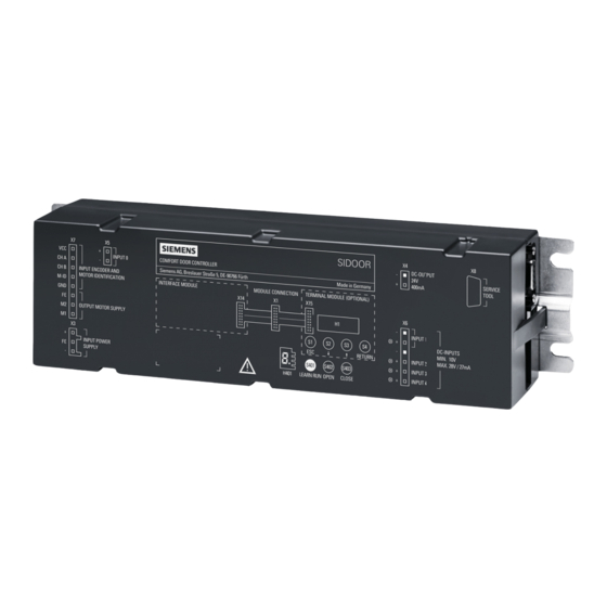
Page 129: Controllers
Controllers Description of controller Overview SIDOOR ATD4xxW INPUT 0 INTERFACE MODULE (OPTIONAL) ① Connecting terminals ② Relay module / PROFIBUS module / PROFINET module ③ Service buttons/Minimal editor ④ Terminal module Installing the control unit Requirement The installation site must fulfill the following requirements: •... - Page 130 Controllers 5.2 Installing the control unit • Maximum distance from the power supply on account of the cable length: – SIDOOR NT40 / SIDOOR TRANSFORMER / SIDOOR TRANSFORMER UL: 1.5 m • Maximum distance from the geared motor on account of the cable length: –...
- Page 131 Controllers 5.2 Installing the control unit Installation Proceed as follows to install the controller: Steps Figure 1. Drill the holes for the screws as shown in the dimension drawing. 2. Secure the controller with 4 (M6 x 10) screws. Installation on a mounting rail You need the SIDOOR standard rail mounting to mount a SIDOOR controller on a standard mounting rail.
-
Page 132: Wiring Instructions
Controllers 5.3 Wiring instructions Proceed as follows to mount the standard rail mounting: Steps Figure Select either a vertical or horizontal Vertical orientation for mounting the control‐ ler on the standard mounting rail. Screw the SIDOOR standard rail mounting tightly to the controller with 2 (M4 x 6) screws. - Page 133 Controllers 5.3 Wiring instructions Terminal information and wiring rules Table 5-1 Terminal information for SIDOOR ATD4xxW Interface Name Terminal Tool Solid con‐ Stranded Strip‐ ductor conductor ping in‐ sulation Input power sup‐ WAGO: 1x 1.5-2.5 1x 1.5-2.5 15 - 12 - 8-9 mm 721-103/026-045 0.6X3.5...
-
Page 134: Connecting Terminals
Controllers 5.4 Connecting terminals Connecting terminals 5.4.1 Digital input signals Slot X6 You can connect certain signals for drive functions at the inputs Input 1, Input 2, Input 3, Input 4 (X6) and Input 0 (X5). The following table shows how the drive function and input are assigned depending on the control unit. - Page 135 Controllers 5.4 Connecting terminals Note To avoid issuing unintentional door commands, remove the terminals X6 and X5 before changing the FBLOCK input configuration. Note SIDOOR ATD401W In the delivery state of the control unit ATD401W the "Default input" configuration is specified for the input signals Input 0 to Input 4 and the parameter for the default command mode (p100) is set to "FBLOCK + relay".
- Page 136 Controllers 5.4 Connecting terminals Terminal circuit diagrams Here you will find an overview of the signals for drive functions at slots X5 and X6, see section Digital input signals (Page 123), Table 4-2 (Page 132). Table 5-3 Terminal circuit diagrams for digital input signals a.
-
Page 137: Voltage Output
Controllers 5.4 Connecting terminals Here you will find an overview of the signals for drive functions at the X5 and X6 slots, see section Digital input signals, Table 4-2 (Page 132). You can find information on safe digital control Door OPEN/CLOSE with emergency stop via 3 digital inputs in the section Concept of safe digital control of Door OPEN/CLOSE with emergency stop via 3 digital inputs. -
Page 138: Relay And Fieldbus Interfaces
Controllers 5.5 Relay and fieldbus interfaces Relay and fieldbus interfaces 5.5.1 Relay module Overview ① ② ③ ④ Protective cover ⑤ Fixing screw for the protective cover Figure 5-1 Relay module ATD4xxW for industrial applications System Manual, 06/2022, A5E51901827B AA... - Page 139 Controllers 5.5 Relay and fieldbus interfaces Task The relay module's relay contacts can be used to report the following door states to the higher- level controller: Table 5-5 SIDOOR ATD401W door states Relay con‐ Designation Function tact CLOSE The system's internal door state "closed" is signaled via this relay (relay contact is closed). This (closed) state is not only position-dependent.
- Page 140 Controllers 5.5 Relay and fieldbus interfaces Procedure Note Specifications for connecting the relay module • The cables connected must be suitable for the voltage used and have appropriate (double or reinforced) insulation. Cables with an external diameter of 6 to 7 mm are recommended. •...
-
Page 141: Profibus
Download SIEM81BA.GSD The GSD file is available online at Industry online support (http:// support.automation.siemens.com/WW/view/en/99008084). You can find explanations of the basic functions and communication properties of the DP slave in the section PROFIBUS communication (Page 145). ATD4xxW for industrial applications... - Page 142 Controllers 5.5 Relay and fieldbus interfaces Task The PROFIBUS module enables the SIDOOR ATD420W door controller to be connected to a PROFIBUS fieldbus. Interface The ATD420W system is implemented as DP slave using the DP-V0 protocol. Data transfer is cyclic with a class 1 DP master.
- Page 143 Controllers 5.5 Relay and fieldbus interfaces DIP switches (S501) The DIP switches (S501) on the device are used to set the PROFIBUS address of the DP slave. ① Status: 1≙ on ② Status: 0 ≙ off ③ DIP switch without function ④...
-
Page 144: Wiring And Connecting Profibus Connectors
Wiring and connecting PROFIBUS connectors Requirement NOTICE PROFIBUS connector Use only the recommended PROFIBUS connectors from Siemens. For more, see also section Accessories (Page 41). NOTICE Material damage resulting from the connection of a PROFIBUS connector to service connection X8 Connecting a PROFIBUS connector to service connection X8 can damage the SIDOOR controller and the connected device. -
Page 145: Wiring And Connecting Relay Outputs
Controllers 5.5 Relay and fieldbus interfaces Table 5-7 Assignment of X705 Assignment Description Not connected Not connected RS 485P RS 485 interface (receive and send signals (+)) Note: For 6GK1500-0FC10: "B" (red) CNTR-P Repeater direction control Interface ground 5 V max. 10 mA, to be used in connector for bus network terminator only Not connected RS 485N RS 485 interface (receive and send signals (-)) - Page 146 Controllers 5.5 Relay and fieldbus interfaces X100.1 X100.2 X100.3 X100.4 Relay control Table 5-8 Relay control for PROFIBUS module Terminal Assignment Description X100.1 CLOSE The relay is additionally influenced by the sensor configuration (parameter p4600). For more, see also section Sensors and external sensor interface module (ATD4xxW) X100.2 (closed) (Page 166).
-
Page 147: Profibus Communication
Controllers 5.5 Relay and fieldbus interfaces 5.5.2.4 PROFIBUS communication Parameter assignment The DP master transfers parameters during initialization of the DP slave. This includes the transfer of standard parameters and specific SIDOOR parameters for the device. The specific parameters are written in the GSD file. No user data can be exchanged without initialization. The DP master sends the parameters to the DP slave in a set parameters telegram. - Page 148 Controllers 5.5 Relay and fieldbus interfaces In order to establish error-free, stable communication, the settings on the connected SIDOOR controller (internal bus) have to be matched. Table 5-9 User parameter byte 1 Bit 7 Bit 6 Bit 5 Bit 4 Bit 3 Bit 2 Bit 1 Bit 0 User parameter byte 1 Data communication Data communication is deactivated if this bit is set to 0.
- Page 149 Controllers 5.5 Relay and fieldbus interfaces Table 5-11 User parameter byte 3 Bit 7 Bit 6 Bit 5 Bit 4 Bit 3 Bit 2 Bit 1 Bit 0 User parameter byte 1 Telegram type The telegram type is set with bits 0 to 2. Codes: Standard telegram = 0000 Mirror telegram = 0001...
- Page 150 Controllers 5.5 Relay and fieldbus interfaces The configuration described gives the following code for the standard module: 0xC1 0x15 0x15 0x00 Diagnostics Extensive diagnostic possibilities are supported in the PROFIBUS DP. A DP master can query the current diagnostics from the DP slave at any time. Diagnostic telegrams can write additional device-specific diagnostics in the GSD file next to the standard diagnostics.
-
Page 151: Profinet
Controllers 5.5 Relay and fieldbus interfaces 5.5.3 PROFINET 5.5.3.1 PROFINET module Overview H1301 H1300 H1302 H1021 H1022 H1011 H1012 ① Cable ties ② X1000 - Port 2 ③ X1000 - Port 1 ④ X100 ⑤ Protective cover The ASIC of the type "ERTEC200P" is used for the PROFINET connection. Ethernet is used as the transmission technology. - Page 152 Controllers 5.5 Relay and fieldbus interfaces LED signals The following five status LEDs are available on the PROFINET module: Color Description Position Green Relay K1 picked up H1301 H1300 LED H1 switches on when the controller has detected the H1302 H1021 H1022 CLOSED position and the pulse generator ceases to output...
- Page 153 Table 5-15 GSD files Scheme GSD file 2.31 GSDML-V2.31-Siemens-SIDOOR-TD430W-20140829.xml GSDML-V2.3-Siemens-SIDOOR-TD430W-20140829.xml 2.25 GSDML-V2.25-Siemens-SIDOOR-TD430W-20140829.xml The GSD files are equivalent in terms of the ATD430W controller's functional scope. PROFINET communication Besides using the MAC address and the IP address, PROFINET also uses a device name to identify PROFINET devices.
- Page 154 Controllers 5.5 Relay and fieldbus interfaces When the device is used for the first time, it has the pre-configured IP address 192.168.0.1 (subnet mask 255.255.255.0). Note If reset to the factory defaults, the pre-configured IP address is deleted and set to 0.0.0.0. If the IP address is assigned by the IO controller based on the system configuration, the retentively stored IP address is deleted and is replaced with 0.0.0.0 in accordance with the PROFINET standard.
- Page 155 Controllers 5.5 Relay and fieldbus interfaces • Port-related statistics (PDEV) • Automatic addressing (DCP) • Media redundancy (MRP) • Isochronous data exchange (IRT) Cyclic data exchange Cyclic data communication contains the data that the central processing unit sends to the IO devices so that it can be output to the outputs as well as the data that an IO device reads in at its inputs and sends to the central processing unit for processing.
- Page 156 Controllers 5.5 Relay and fieldbus interfaces The I&M records consists of the following parameters: Table 5-16 I&M 0 and I&M 1 to 4 data I&M record Fields (standardized) Access authorization I&M 0 MANUFACTURER_ID Read ORDER_ID SERIAL_NUMBER HARDWARE_REVISION SOFTWARE_REVISION REV_COUNTER PROFILE_ID PROFILE_SPECIFIC_TYPE IM_VERSION IM_SUPPORTED...
-
Page 157: Wiring And Connecting A Profinet Connector
Controllers 5.5 Relay and fieldbus interfaces Isochronous data exchange The ATD430W IO device also supports the IRT protocol and thus class C functionality (CC-C). This supports isochronous data exchange up to 250 µs. The IO device forwards all data isochronously. The application program on the ATD430W does not operate isochronously. -
Page 158: Wiring And Connecting Relay Outputs
Controllers 5.5 Relay and fieldbus interfaces Connection The wired RJ45 connectors are connected to the two X1000 Port 1 and X1000 Port 2 terminals. X1000 Port 2 Port 1 5.5.3.3 Wiring and connecting relay outputs Wiring The PROFINET module has 2 relay outputs (closer contact). A maximum voltage of 42.0 V (SELV according to EN60950-1) may be applied to the PROFINET module. -
Page 159: Profinet Communication
Controllers 5.5 Relay and fieldbus interfaces Relay control Table 5-18 Relay control for PROFINET module Terminal Assignment Description X100.1 CLOSE The relay is additionally influenced by the sensor configuration (parameter p4600). For more, see also section Sensors and external sensor interface module (ATD4xxW) X100.2 (closed) (Page 166). - Page 160 Controllers 5.5 Relay and fieldbus interfaces The structure of the 8-byte startup parameter record 1 is described in the following: Table 5-19 Startup parameter record byte 1 Data exchange and baud rate parameter Data communication Data communication on the internal bus is deactivated if this bit is set to 0.
- Page 161 Controllers 5.5 Relay and fieldbus interfaces Table 5-21 Startup parameter record byte 3 Telegram type parameter Telegram type The telegram type on the internal bus is set via bits 0 to 2. The following coding results: Default telegram = 0000 Mirror telegram = 0001 Broadcast = 0010 Special telegram = 0011...
- Page 162 Controllers 5.5 Relay and fieldbus interfaces Slot Subslot Module Submodule Description 8002 Port 2 0001 22 bytes IO (4 words of PKW and 7 words of PZD are mapped) Diagnostics The internal communication bus between the SIDOOR controller and the communication module is monitored by the master driver of the communication module (PROFINET module).
-
Page 163: Local/Master Operation
Controllers 5.5 Relay and fieldbus interfaces IO supervisor A PROFINET IO supervisor is an engineering station in a system, for example, that can have temporary access to the field devices for commissioning purposes. IO device The PROFINET IO device is a process-oriented field device that is connected in a distributed fashion. -
Page 164: Master Monitoring
Controllers 5.5 Relay and fieldbus interfaces remains in the "S1:Z_switching on inhibited" state (see Figure 5-4 Sequential control state graph (Page 163)). For safety reasons, the controller automatically switches to local mode under the following conditions: • Service button S402 (Open), S403 (Close) or S401 (Learn run) operated •... -
Page 165: Sequential Control
Controllers 5.6 Sequential control Sequential control The following figure illustrates the sequential control of SIDOOR ATD4xxW control unit in the form of a state graph: Figure 5-4 Sequential control state graph ATD4xxW for industrial applications System Manual, 06/2022, A5E51901827B AA... - Page 166 Controllers 5.6 Sequential control The following table describes the properties of different states of the sequential control and their impact on the system with respect to the slave (= SIDOOR control unit). Status Status word Control System impact Comment/note word S1: Z_EINSCHALTSPERRE Valid Invalid...
- Page 167 Controllers 5.6 Sequential control Switching the SIDOOR control unit to operating mode The door drive can be transferred to operating mode via the sequential control. The following illustration shows an example for the two necessary steps: Step 1 Name Value Name Value Ready for switching on...
-
Page 168: Sensors And External Sensor Interface Module
Controllers 5.7 Sensors and external sensor interface module Sensors and external sensor interface module 5.7.1 Overview The signals in the figure below are processed and generated via the internal signal logic of SIDOOR ATD4xxW controllers. The system reaction to the displayed signals is described in the section Optional safety settings (Page 112). - Page 169 Controllers 5.7 Sensors and external sensor interface module Signal Meaning Source ESPE Electrosensitive protective equip‐ Function-tested 0 active local signal (terminal X6, ment "Input 1") Pressure-sensitive edge Function-tested 0 active local signal (terminal X6, "Input 1") Configuration of the connected sensor type The sensor type of the sensor connected to "Input 1"...
- Page 170 Controllers 5.7 Sensors and external sensor interface module As an alternative to the ESPE system, a pressure sensitive edge (SR) can be connected to the SIDOOR ATD4xxW control unit. The figure below is a schematic diagram of a pressure sensitive edge according to ISO13856-2 connected to a SIDOOR control unit: ATD4xxW for industrial applications System Manual, 06/2022, A5E51901827B AA...
- Page 171 The following figure schematically shows the interconnection of a type 3 or type 4 ESPE with the SIDOOR ATD4xxW control unit using SIEMENS 3SK1111-2AB30 switchgear. For this series connection of these three units (1x sensor PL>= d, 1x switchgear PL>=d, 1x ATD4xxW PL d), this results in an overall PL of PL d according to EN ISO 13849-1:2015 section 6.3:...
-
Page 172: Sensor Function Test
Controllers 5.7 Sensors and external sensor interface module 5.7.2 Sensor function test When an ESPE or pressure sensitive edge is connected, equipment for a periodic test is required. This test is intended to detect a dangerous failure before the dangerous function is used. If the SIDOOR control unit's sensor logic is configured for an ESPE or pressure sensitive edge, the "TestOUT"... -
Page 173: Reaction Times
Controllers 5.7 Sensors and external sensor interface module 5.7.3 Reaction times The reaction time to an interrupted light array (ESPE) or a pressure-sensitive edge can be determined by measuring the motor current reduction. To this end, the ESPE or pressure- sensitive edge system can be activated (interrupted or triggered) during constant travel so that the drive reverses. -
Page 174: Technical Specifications
38 V (DC) Protection in case of DC supply Use of a circuit breaker in the supply path according to 60898-1, 8A, C-characteristic type SIEMENS: 5SY4108-7 or 5SY4108-7KK11 Input current I²t, min. 30 A²·s Encoder supply Output voltage (DC) 24 V;... - Page 175 Controllers 5.8 Technical specifications Article number 6FB1141-1AT11-3W 6FB1141-2AT10-3W 6FB1141-3AT10-3W Active power input (standby mode) Digital inputs Control inputs isolated Control inputs p-switching Input voltage 10 V; Observe polarity ! • permissible voltage at in‐ put, min. 28 V; Observe polarity ! •...
- Page 176 Controllers 5.8 Technical specifications Article number 6FB1141-1AT11-3W 6FB1141-2AT10-3W 6FB1141-3AT10-3W PNO certificate China RoHS compliance Standard for EMC EN 61000-6-2 / EN 61000-6-4 Standard for safety EN 61010-1 / EN 61010-2-201 / UL 61010-1 / UL 61010-2-201 / EN ISO 13849-1 Cat. 2 PL d Ambient conditions Ambient temperature during operation...
- Page 177 Controllers 5.8 Technical specifications Dimension drawing Figure 5-7 Controller ATD4xxW for industrial applications System Manual, 06/2022, A5E51901827B AA...
-
Page 178: Operation And Configuration Of The Control Unit
Controllers 5.9 Operation and configuration of the control unit Operation and configuration of the control unit The service buttons can be used to operate the controller. The following options are available to parameterize the controller. 1. Parameter assignment via the fieldbus PKW interface 2. -
Page 179: Service Buttons
Controllers 5.9 Operation and configuration of the control unit Note ATD420W / ATD430W Access protection to the parameters The write protection must be activated via parameter p90 for the SIDOOR ATD420W and ATD430W controllers. This way the change of parameters is blocked via the service menu. Note After the optimal parameter settings have been determined, note them in the configuration protocol (see appendix Configuration record (Page 339)). - Page 180 Controllers 5.9 Operation and configuration of the control unit Learn run button You can start a learn run with the learn run button (S401). Note Two types of learn run can be carried out. See section Learn run (Page 46). Learn run (when the supply voltage is applied) Table 5-28 Starting a learn run when the line voltage is applied...
- Page 181 For more information, refer to the SIDOOR SERVICE TOOL (Page 271) section, the SIDOOR SUPPORT App Function Manual and the SIDOOR SOFTWARE KIT Operating Instructions (http://support.automation.siemens.com/WW/view/en/92711247). ATD4xxW for industrial applications System Manual, 06/2022, A5E51901827B AA...
-
Page 182: Parameter Assignment Via The Terminal Module
Controllers 5.9 Operation and configuration of the control unit See also SIDOOR SUPPORT App Function Manual (https://support.industry.siemens.com/cs/de/en/view/ 109802679) 5.9.2 Parameter assignment via the terminal module Overview TERMINAL MODULE RETURN ① Digital display ② Escape key ③ Menu selection key ④... -
Page 183: Parameter Assignment Using Additional Devices
The SIDOOR USER SOFTWARE is part of the SIDOOR SOFTWARE KIT. You can find a detailed description of the SIDOOR SOFTWARE KIT in the SIDOOR SOFTWARE KIT Operating Instructions (http://support.automation.siemens.com/WW/view/en/92711247). • SIDOOR SERVICE TOOL A detailed description of the SIDOOR SERVICE TOOL is available in the section SIDOOR SERVICE TOOL (Page 271). -
Page 184: Adjustable Parameters
Controllers 5.9 Operation and configuration of the control unit 5.9.4 Adjustable parameters 5.9.4.1 Driving curve The optimum drive characteristics of the door are calculated and maintained continuously. The driving curve transitions are rounded off so that the door movement is smooth and jerk-free. v* Speed open Speed close ①... -
Page 185: Forces
Controllers 5.9 Operation and configuration of the control unit 5.9.4.2 Forces The following forces and currents can be configured for the travel curve: Continuous torque (power) OPEN Continuous torque in the door position OPEN. This parameter is effective when an open command is present and the door is in the OPEN position. - Page 186 Controllers 5.9 Operation and configuration of the control unit Figure 5-10 Current – force – motor characteristic in opening direction for drive transmission ratio 176 mm/rev Adjustment ranges The parameter can be adjusted in accordance with the adjustment ranges of the parameters (see section Profiles and adjustment ranges (Page 329)).
- Page 187 Controllers 5.9 Operation and configuration of the control unit Figure 5-11 Current – force – motor characteristic in closing direction for output transmission ratio 176 mm/rev Adjustment ranges The value of the parameter must be selected so that the door moves across the entire door width in the closing direction if a close command is present.
-
Page 188: Parameter Assignment
Controllers 5.9 Operation and configuration of the control unit Example: Closing weight = 4 kg Desired static force limit CLOSE = 150 N The counterweight of 4 kg corresponds to a force of 40 N. The force limit then has to be adjusted to 150 N –... - Page 189 Controllers 5.9 Operation and configuration of the control unit Driving parameters Note For safety reasons, changes to the driving parameters are only accepted when the controller is at a complete stop. Note Write protection When write protection is activated (see Table 5-31 Other parameters (Page 188)), the drive curve parameters can only be changed via the SIDOOR user commissioning software and the PKW interface.
- Page 190 Controllers 5.9 Operation and configuration of the control unit Parameter ID Unit Parameter name Description p3680 Idle torque CLOSE Continuous torque in closed position. The current gener‐ ates a continuous torque against the end position of the door in the closing direction. p3681 Peak torque close Peak torque close in closed position for approx.
- Page 191 Controllers 5.9 Operation and configuration of the control unit Parameter ID Adjustment range Factory set‐ Unit Description ting 0 ≙ deactivated — Write protection 1 ≙ activated Activates (1) or deactivates (0) write protection for all driving curve parameters in the service menu. As of V1.09: When write protection is activated via parameter p90, the FBLOCK configuration, the force for the learn run and the configuration of digital input...
- Page 192 Controllers 5.9 Operation and configuration of the control unit Parameter ID Adjustment range Factory set‐ Unit Description ting p100 0 = FBLOCK + Bus — Default command mode: 1 = FBLOCK + relay For the ATD420W, ATD430W control units the com‐ mand input via the bus system is activated in the de‐...
- Page 193 Controllers 5.9 Operation and configuration of the control unit Fieldbus parameters Table 5-32 Fieldbus parameters Parameter ID Adjustment range Factory setting Description Communication channel p2020 0 ≙ 9600 Baud rate 1 ≙ 19200 2 ≙ 38400 3 ≙ 57600 4 ≙ 115200 5 ≙...
- Page 194 Controllers 5.9 Operation and configuration of the control unit Calibration and function parameters Table 5-33 Calibration and function parameters Parameter ID Adjustment range Factory set‐ Unit Description ting Advanced functions p1200 50 … 1000 mm/s Speed from which vandalism protection is activated. 0 ≙...
- Page 195 Controllers 5.9 Operation and configuration of the control unit Parameter ID Adjustment range Factory set‐ Unit Description ting p1231 1 … 100 Threshold value for digital detection of external slide support during the opening movement (The proportion of force from which AssistedDrive is detected in relation to the learnt reference value) p1232 1 …...
- Page 196 Controllers 5.9 Operation and configuration of the control unit Parameter ID Adjustment range Factory set‐ Unit Description ting <V1.10: r2103 300 … 5000 Door width >=V1.10: As of V1.10: Writable p2103 <V1.10: r2104 0 … 300 Friction in open direction >=V1.10: As of V1.10: Writable p2104...
- Page 197 Controllers 5.9 Operation and configuration of the control unit Parameter ID Adjustment range Factory set‐ Unit Description ting p2205 0..500 Initial operation: Because the absolute position is not known in initial operation, the width in Close direction is specified here starting from the current position.
- Page 198 Controllers 5.9 Operation and configuration of the control unit The parameters in the table below refer to the closing direction only. Table 5-35 Obstruction and reversing parameters (in the closing direction) Parameter ID Adjustment range Factory set‐ Unit Description ting Timing p3852 0 …...
- Page 199 Controllers 5.9 Operation and configuration of the control unit Parameter ID Adjustment range Factory set‐ Unit Description ting p3865 0 … 65535 2000 Wait time before each reverse p3866 0 … 65535 Reversing distance 0 ≙ full reverse p3867 0 ≙ deenergize —...
- Page 200 Controllers 5.9 Operation and configuration of the control unit Parameter ID Adjustment range Factory set‐ Unit Description ting p3880 0 ≙ deenergize — Drive control after all retries have been executed (if reversing is not configured) 1 ≙ stop 2 ≙ open 3 ≙...
- Page 201 Controllers 5.9 Operation and configuration of the control unit Parameter Name Description p20003 DCMD_DI1_Q5 Rising (positive) edge Output is active for one cycle when input edge is detected. The entered drive order (DCMD) is automatically latched p20004 DCMD_DI1_Q6 Falling (negative) edge (stored).
- Page 202 Controllers 5.9 Operation and configuration of the control unit Parameter Name Description p20039 DCMD_SBIT0_Q47 Level-controlled output; output follows the input inverted p20043 DCMD_SBIT1_Q51 p20047 DCMD_SBIT2_Q55 p20051 DCMD_SBIT3_Q59 p20055 DCMD_SBIT4_Q63 p20015 DCMD_AND0_Q17 Output is logically ANDed with inputs. a discrepancy analysis of the inputs can be additionally activated.
- Page 203 Controllers 5.9 Operation and configuration of the control unit Parameter Name Description Position block (as of V1.12) p20061 DCMD_POS_Q69 Output is active as long as the door position is within the parameterized range. FBLOCK-REF parameters The inputs of the various F blocks can be connected or linked to any "Q" outputs (signal sources) via the following FBLOCK-REF parameters.
- Page 204 Controllers 5.9 Operation and configuration of the control unit Parameter ID Name Description p20119 REF_ACK Fault acknowledgement (preceded by 5 s ON delay) p20120 REF_BATTMODE Emergency power mode (drive order is automatically latched until next end stop is reached) COUNTER p20121 REF_COUNTER_IN Count input of the counter (a positive edge increments the counter)
-
Page 205: Geared Motors
Geared motors Description Overview Figure 6-1 Geared motors (pinion left*) * The gear outlet direction is defined as left or right when viewing the gear unit from the front. The maintenance-free drive unit consists of a speed-controlled DC motor with non-self-locking gearing. -
Page 206: Installation
The rubber-metal anti-vibration mount, mounting bracket, tensioning device / mounting bracket, deflector unit / deflector pulley, and door clutch holder are optional components and can be obtained from Siemens. You can find additional information in the section Technical specifications (Page 212). - Page 207 Geared motors 6.2 Installation • Use washers to maintain the centering in the shaft extension for removal. • If necessary, fully balance the motor with output elements according to ISO 1940. Figure 6-2 Fitting and removing output elements; A = intermediate washer (for maintaining the centering in the shaft extension) Procedure WARNING...
- Page 208 Geared motors 6.2 Installation The mechanical installation of the geared motor is performed in the following steps: 1. Mount the geared motor on the rubber-metal anti-vibration motor mounting. SIDOOR M3 / MDG3 SIDOOR M4 / MDG4 / M5 / MDG5 Then, if required, mount the motor mounting (rubber-bonded metal) on the mounting bracket.
- Page 209 Geared motors 6.2 Installation Ensure that the drive pinion and deflector pulley are aligned when doing so. They have to be exactly aligned to ensure a long drive service life. 3. Pass the toothed belt over the deflector pulley and drive pinion. Place both open ends of the toothed belt in the door clutch holder.
- Page 210 Geared motors 6.2 Installation Span tension The span tension T of the belt is calculated as follows: T: Span tension [N] k: Weight per meter [kg/m] L: Belt length [m] f: Frequency (Hz) The following table shows the natural frequency (f) of the belt for the recommended span tension (T) at different belt lengths (L).
-
Page 211: Connecting Terminals
Geared motors 6.3 Connecting terminals You will recognize the correct belt tension by how far the belt is pressed in (B). The depth (B) the belt is pressed in depends on the distance between the drive pinion and deflector pulley (A). The following depths of the pressed-in belt (B) apply as a function of the distance between the drive pinion and deflector pulley (A). - Page 212 Geared motors 6.3 Connecting terminals Table 6-1 Motor plug (slot X7) Terminal Signal SIDOOR M3 / M4 / M5 wire color (X7) +5 V Gray Channel A Yellow Channel B Green Motor ID Brown White Yellow/green Motor + Black 1 Motor - Black 2 Note...
- Page 213 Geared motors 6.3 Connecting terminals Terminal Motor plug 4 pin. Motor plug 5 pin Signal SIDOOR MDG3 / MDG4 / (X7) (Power) (Encoder) MDG5 wire color Motor + Brown White Motor - Blue Black ATD4xxW for industrial applications System Manual, 06/2022, A5E51901827B AA...
-
Page 214: Technical Specifications
Geared motors 6.4 Technical specifications Technical specifications 6.4.1 Technical specifications MDG3 R/L Article number 6FB1103-0AT13-4MB1 6FB1103-0AT14-4MB1 General information Product brand name SIDOOR SIDOOR Product type designation MDG3 R MDG3 L Product version Right gearbox output with groove Left gearbox output with groove and feather key and feather key Supply voltage... - Page 215 Geared motors 6.4 Technical specifications Article number 6FB1103-0AT13-4MB1 6FB1103-0AT14-4MB1 Fixed connecting cable Dimensions Diameter of output gear, min. 28 mm 28 mm Diameter of output gear, max. 122 mm 122 mm Height of motor 98 mm 98 mm Length of motor 264 mm 264 mm Diameter of motor...
-
Page 216: Technical Specifications Mdg4 R/L
Geared motors 6.4 Technical specifications 6.4.2 Technical specifications MDG4 R/L Article number 6FB1103-0AT13-3MC2 6FB1103-0AT14-3MC2 General information Product brand name SIDOOR SIDOOR Product type designation MDG4 R MDG4 L Product version Right gearbox output with groove Left gearbox output with groove and feather key and feather key Supply voltage... - Page 217 Geared motors 6.4 Technical specifications Article number 6FB1103-0AT13-3MC2 6FB1103-0AT14-3MC2 Height of motor 115 mm 115 mm Length of motor 303 mm 303 mm Diameter of motor 63 mm 63 mm Width of gearbox 106 mm 106 mm ATD4xxW for industrial applications System Manual, 06/2022, A5E51901827B AA...
-
Page 218: Technical Specifications Mdg5 R/L
Geared motors 6.4 Technical specifications 6.4.3 Technical Specifications MDG5 R/L Article number 6FB1103-0AT13-3MG2 6FB1103-0AT14-3MG2 General information Product brand name SIDOOR SIDOOR Product type designation MDG5 R MDG5 L Product version Right gearbox output with groove Left gearbox output with groove and feather key and feather key Supply voltage... - Page 219 Geared motors 6.4 Technical specifications Article number 6FB1103-0AT13-3MG2 6FB1103-0AT14-3MG2 Height of motor 124 mm 124 mm Length of motor 348 mm 348 mm Diameter of motor 80 mm 80 mm Width of gearbox 109 mm 109 mm ATD4xxW for industrial applications System Manual, 06/2022, A5E51901827B AA...
-
Page 220: Technical Specifications M3 R/L
Geared motors 6.4 Technical specifications 6.4.4 Technical specifications M3 R/L Article number 6FB1103-0AT11-4MB0 6FB1103-0AT10-4MB0 General information Product brand name SIDOOR Product type designation M3 R M3 L Product version With driven gear on the right With driven gear on the left Supply voltage Rated value (DC) 30 V... -
Page 221: Technical Specifications M4 R/L
Geared motors 6.4 Technical specifications 6.4.5 Technical specifications M4 R/L Article number 6FB1103-0AT11-3MC0 6FB1103-0AT10-3MC0 General information Product brand name SIDOOR SIDOOR Product type designation M4 R M4 L Product version With driven gear on the right With driven gear on the left Supply voltage Rated value (DC) 30 V... -
Page 222: Technical Specifications M5 R/L
Geared motors 6.4 Technical specifications 6.4.6 Technical specifications M5 R/L Article number 6FB1103-0AT11-3MD0 6FB1103-0AT10-3MD0 General information Product brand name SIDOOR Product type designation M5 R M5 L Product version With driven gear on the right With driven gear on the left Supply voltage Rated value (DC) 30 V... -
Page 223: Technical Specifications For Rubber-Metal Anti-Vibration Mount
Geared motors 6.4 Technical specifications 6.4.7 Technical specifications for rubber-metal anti-vibration mount Article number 6FB1104-0AT01-0AD0 6FB1104-0AT02-0AD0 General technical data: Product brand name SIDOOR Installation/ mounting/ dimensions: Width of rubber-bonded metal Height of rubber-bonded metal Length of rubber-bonded metal 6.4.8 Technical specifications for mounting bracket Article number 6FB1104-0AT01-0AS0 6FB1104-0AT02-0AS0... -
Page 224: Technical Specifications For Door Clutch Holder
Geared motors 6.4 Technical specifications 6.4.10 Technical specifications for door clutch holder Article number 6FB1104-0AT02-0CP0 6FB1104-0AT01-0CP0 General technical data: Product brand name SIDOOR Installation/ mounting/ dimensions: Width of door clutch holder Height of door clutch holder Length of door clutch holder Width of toothed belt 6.4.11 Technical specifications for toothed belt... -
Page 225: Technical Specifications Motor Cable (Cable Mdg)
Geared motors 6.4 Technical specifications 6.4.13 Technical specifications motor cable (cable MDG) Article number 6FB1104-0AT05 6FB1104-0AT10 6FB1104-0AT15 6FB1104-0AT20 -0CB2 -0CB2 -0CB2 -0CB2 General information Product brand name SIDOOR Product type designa‐ CABLE- CABLE- CABLE- CABLE- tion MDG2-5M MDG2-10M MDG2-15M MDG2-20M Product version Cable set Degree and class of pro‐... -
Page 226: Dimension Drawing Of Sidoor M3 With Rubber-Metal Anti-Vibration Mount And Mounting Bracket
Geared motors 6.4 Technical specifications 6.4.14 Dimension drawing of SIDOOR M3 with rubber-metal anti-vibration mount and mounting bracket ① ④ Geared motor SIDOOR M3 L / MDG3 L 7 x M6x16 safety hexagonal screws ② ⑤ 4 x M5x10 safety hexagonal screws SIDOOR mounting bracket ③... -
Page 227: Dimension Drawing Sidoor Mdg3
Geared motors 6.4 Technical specifications 6.4.15 Dimension drawing SIDOOR MDG3 Front view Figure 6-5 SIDOOR MDG3 Front view Side view Figure 6-6 Dimension drawing SIDOOR MDG3 ATD4xxW for industrial applications System Manual, 06/2022, A5E51901827B AA... -
Page 228: Dimension Drawing Of Sidoor M4 With Rubber-Metal Anti-Vibration Mount And Mounting Bracket
Geared motors 6.4 Technical specifications 6.4.16 Dimension drawing of SIDOOR M4 with rubber-metal anti-vibration mount and mounting bracket Gear motor (left) Motor vibration schock mount 6 x Safety hexagonal screws M6x10 7 x Safety Hexagonal screws M6x16 Mounting bracket Motor fastening Figure 6-7 Geared motor with rubber-metal anti-vibration mount and mounting bracket (M4 motor) ATD4xxW for industrial applications... -
Page 229: Dimension Drawing Sidoor Mdg4
Geared motors 6.4 Technical specifications 6.4.17 Dimension drawing SIDOOR MDG4 Front view Figure 6-8 SIDOOR MDG4 Front view ATD4xxW for industrial applications System Manual, 06/2022, A5E51901827B AA... - Page 230 Geared motors 6.4 Technical specifications Side view Figure 6-9 Dimension drawing SIDOOR MDG4 ATD4xxW for industrial applications System Manual, 06/2022, A5E51901827B AA...
-
Page 231: Dimension Drawing Of Sidoor M5
Geared motors 6.4 Technical specifications 6.4.18 Dimension drawing of SIDOOR M5 Front view Motor on left Motor on right Side view Figure 6-10 SIDOOR M5 Note Rubber-metal anti-vibration mount When installing the M5 motor, use the same rubber-metal anti-vibration mount as for the M4 motor. -
Page 232: Dimension Drawing Sidoor Mdg5
Geared motors 6.4 Technical specifications 6.4.19 Dimension drawing SIDOOR MDG5 Front view Figure 6-11 SIDOOR MDG5 Front view ATD4xxW for industrial applications System Manual, 06/2022, A5E51901827B AA... -
Page 233: Dimension Drawing Of Motor Cable Mdg-Cable
Geared motors 6.4 Technical specifications Side view Figure 6-12 SIDOOR MDG5 Side view 6.4.20 Dimension drawing of motor cable MDG-CABLE Figure 6-13 Motor cable MDG-CABLE ATD4xxW for industrial applications System Manual, 06/2022, A5E51901827B AA... -
Page 234: Dimension Drawing Of Deflector Pulley With Tensioning Device And Mounting Bracket
Geared motors 6.4 Technical specifications 6.4.21 Dimension drawing of deflector pulley with tensioning device and mounting bracket Overhead pulley device 2x Hexagonal screws M6x12 DIN 933 2x Washers 6,4 DIN 125 Tension bar Tension screw M6x30 DIN 933 3x Hexagonal safety srew M6x16 Mounting bracket Tensioning device... -
Page 235: Dimension Drawing Of Door Clutch Holder
Geared motors 6.4 Technical specifications 6.4.22 Dimension drawing of door clutch holder Figure 6-15 Door clutch holder ATD4xxW for industrial applications System Manual, 06/2022, A5E51901827B AA... -
Page 236: Dimension Drawing Sidoor Mdg Pulley
Geared motors 6.4 Technical specifications 6.4.23 Dimension drawing SIDOOR MDG PULLEY Figure 6-16 SIDOOR MDG Pulley transmission ratio 176 mm/rev ATD4xxW for industrial applications System Manual, 06/2022, A5E51901827B AA... -
Page 237: Power Supply
Power supply SIDOOR NT40 7.1.1 Description Note Electromagnetic compatibility The SIDOOR NT40 power supply meets the requirements of the EMC standard EN 61000-6-4. The SIDOOR NT40 power supply can cause interference if used in a residential environment. The commissioning engineer is responsible for interference suppression. Design ①... -
Page 238: Installation
Power supply 7.1 SIDOOR NT40 On the output side, the switch mode power supply supplies a 36 V DC (± 3 %) SELV at a rated output power < 100 W. The device can briefly (< 2 s) deliver a 15 A current to enable fast acceleration (corresponds to a brief power output of 540 W). -
Page 239: Connecting Terminals
Power supply 7.1 SIDOOR NT40 • In order to protect the modules from static electrical discharges, personnel must discharge themselves electrostatically before opening control cabinets or terminal boxes. • It is essential to ensure that the maximum temperature of 55 °C is not exceeded in the mounting position. - Page 240 Power supply 7.1 SIDOOR NT40 The rated data of the output are: Rated output voltage 36 V Rated output current 2.5 A Continuous output power rating <100 W WARNING Dangerous electrical voltage. May cause death, serious injury or property damage. The third line brought out at the output is only a functional grounding connection, this must not be regarded or used as a ground in the sense of a PE connection! Connection specifications...
- Page 241 Power supply 7.1 SIDOOR NT40 Procedure Note Risk of injury through moving mechanical parts. The control system will become ready for operation after the supply line has been connected. If a control signal is present, the door will move in the set direction. Always connect the supply lines last of all! Carry out the following steps in the given order: 1.
-
Page 242: Technical Specifications
Power supply 7.1 SIDOOR NT40 7.1.4 Technical specifications Article number 6FB1112-0AT20-3PS0 General information Product brand name SIDOOR Product type designation NT40 Installation type/mounting Mounting type Four 5 mm screws Supply voltage Rated value (AC) 230 V relative symmetrical tolerance of the supply voltage 15 % Line frequency 50 Hz... - Page 243 Power supply 7.1 SIDOOR NT40 Article number 6FB1112-0AT20-3PS0 Standard for safety EN 61010-1 / EN 61010-2-201 Ambient conditions Ambient temperature during operation -20 °C • min. 55 °C • max. • Remark No direct exposure to the sun Ambient temperature during storage/transportation -20 °C •...
- Page 244 Power supply 7.1 SIDOOR NT40 Safetyp lug (Schuko) Cable length approx. 2 m Power ON LED Cable length approx. 1.5 m Connection for AT controller Figure 7-2 Dimensions of switch mode power supply NT40 ATD4xxW for industrial applications System Manual, 06/2022, A5E51901827B AA...
-
Page 245: Sidoor Transformer
Power supply 7.2 SIDOOR TRANSFORMER SIDOOR TRANSFORMER 7.2.1 Description Design ① Schuko plug 220-240 V AC +/-10% 50/60 Hz ② Length approx. 2 m ③ Connection to the control unit ④ Length approx. 1.5 m ⑤ Height of the mains transformer approx. 65 mm; width approx. 145 mm, depth approx. 126 mm ⑥... -
Page 246: Installation
Power supply 7.2 SIDOOR TRANSFORMER See also Controllers (Page 33) 7.2.2 Installation Requirements The installation site must fulfill the following requirements: • Minimum clearance to surrounding parts: 1 cm • Even mounting surface • Maximum distance from the power supply due to cable length: –... -
Page 247: Connecting Terminals
Power supply 7.2 SIDOOR TRANSFORMER Procedure Proceed as follows to install the transformer: Steps Figure ① 1. Drill the hole for the screw as shown in the dimension drawing. 2. Secure the transformer with 1 screw ① (M6, minimum length 70 mm) a flat metal surface. -
Page 248: Test Voltage
Power supply 7.2 SIDOOR TRANSFORMER 7.2.4 Test voltage Figure 7-4 Diagram test voltage The type test and the manufacturing test can only be performed by the manufacturer. The field can also be performed by the user. Requirements for performing the field test: General The following applies to SIDOOR TRANSFORMER: Disconnect SIDOOR TRANSFORMER from the power supply by pulling out the power plug,... -
Page 249: Technical Specifications
Power supply 7.2 SIDOOR TRANSFORMER 7.2.5 Technical specifications 7.2.5.1 SIDOOR TRANSFORMER Article number 6FB1112-0AT20-2TR0 General information Product brand name SIDOOR Product type designation TRANSFORMER Product version Power supply unit for SIDOOR controllers Installation type/mounting Mounting type Hexagon head bolt M6, L > 70 mm Supply voltage permissible range, lower limit (AC) 220 V... - Page 250 Power supply 7.2 SIDOOR TRANSFORMER Article number 6FB1112-0AT20-2TR0 IP degree of protection IP54 Standards, approvals, certificates CE mark EAC (formerly Gost-R) RoHS conformity China RoHS compliance Standard for EMC EN 12015 / EN 12016 / EN 61000-6-2 / EN 61000-6-3 / EN 61000-3-2 / EN 61000-3-3 Standard for safety Low Voltage Directive (LVD) 2014/35/EU Ambient conditions...
-
Page 251: Dimensional Drawing Sidoor Transformer
Power supply 7.2 SIDOOR TRANSFORMER 7.2.5.2 Dimensional drawing SIDOOR TRANSFORMER Figure 7-5 Dimensions of the SIDOOR TRANSFORMER ATD4xxW for industrial applications System Manual, 06/2022, A5E51901827B AA... -
Page 252: Sidoor Transformer Ul
Power supply 7.3 SIDOOR TRANSFORMER UL SIDOOR TRANSFORMER UL 7.3.1 Description Design ① No mains connection 220-240 V AC +/-10% 50/60 Hz ② Length approx. 2 m ③ Connector for connection to the control unit ④ Length approx. 1.5 m ⑤... -
Page 253: Installation
Power supply 7.3 SIDOOR TRANSFORMER UL The pin assignment at slot X3 is as follows: See also Controllers (Page 33) 7.3.2 Installation Requirements The installation site must fulfill the following requirements: • Minimum clearance to surrounding parts: 1 cm • Flat mounting surface made of metal •... - Page 254 Power supply 7.3 SIDOOR TRANSFORMER UL CAUTION Material damage The connection cables of the transformer cannot be replaced. • Scrap the unit if the line is damaged. Procedure Proceed as follows to install the transformer: Steps Figure ① Drill the hole for the screw as shown in the dimension drawing.
-
Page 255: Connection
Power supply 7.3 SIDOOR TRANSFORMER UL 7.3.3 Connection Requirements WARNING Dangerous electrical voltage! When electrical devices are operated, parts of these devices will necessarily carry dangerous voltages. Failure to observe the operating instructions can therefore lead to serious injuries or material damage. - Page 256 Power supply 7.3 SIDOOR TRANSFORMER UL Procedure • Connect the wires as shown in the drawing. • Be sure to connect the protective ground (green-yellow) correctly. • Ensure that there is a mains disconnecting device near the equipment that is easily accessible clearly marked (for example, using a suitable miniature circuit breaker).
-
Page 257: Test Voltage
Power supply 7.3 SIDOOR TRANSFORMER UL 7.3.4 Test voltage Figure 7-7 Diagram test voltage The type test and the manufacturing test can only be performed by the manufacturer. The field can also be performed by the user. Requirements for performing the field test: General Disconnecting SIDOOR TRANSFORMER UL disconnect the connection to the SIDOOR control circuit device. -
Page 258: Technical Specifications
Power supply 7.3 SIDOOR TRANSFORMER UL 7.3.5 Technical specifications 7.3.5.1 SIDOOR TRANSFORMER UL Article number 6FB1112-0AT21-2TR0 General information Product version Power supply unit for SIDOOR controllers Installation type/mounting Mounting type Hexagon head bolt M6, L > 70 mm Supply voltage permissible range, lower limit (AC) 220 V permissible range, upper limit (AC) - Page 259 Power supply 7.3 SIDOOR TRANSFORMER UL Article number 6FB1112-0AT21-2TR0 Standard for safety UL 61010-1, CSA C22.2 No. 61010-1-12, Low Volt‐ age Directive (LVD) 2014/35/EU Ambient conditions Ambient temperature during operation -20 °C • min. 55 °C • max. No direct exposure to the sun •...
-
Page 260: Dimension Drawing Sidoor Transformer Ul
Power supply 7.3 SIDOOR TRANSFORMER UL 7.3.5.2 Dimension drawing SIDOOR TRANSFORMER UL Figure 7-8 Dimension drawing TRANSFORMER UL ATD4xxW for industrial applications System Manual, 06/2022, A5E51901827B AA... -
Page 261: Sitop Psu8200 13A/36V 3-Phase
SITOP PSU8200 may be used only as of firmware version ATD4xxW ≥ 1.04. Fuse protection An MCB according to EN 60898‑1, 8 A, C‑characteristic of the type SIEMENS: 5SY4108‑7 is to be inserted into the supply network by the customer. -
Page 262: Installation
Power supply 7.4 SITOP PSU8200 13A/36V 3-phase 7.4.2 Installation A miniature circuit breaker (type SIEMENS: 5SY4108-7) is an absolute requirement for SITOP PSU8200. The circuit breaker must be mounted close to the SIDOOR controller (at a similar ambient temperature). ATD4xxW for industrial applications... -
Page 263: Technical Specifications
Power supply 7.4 SITOP PSU8200 13A/36V 3-phase 7.4.3 Technical specifications Core statement Order number 6EP3446-8SB10-0AY0 Product SITOP PSU8200 Power supply, type 36 V/13 A Input Input 3-phase AC Rated voltage value Vin rated 400 ... 500 V Voltage range AC 320 ... - Page 264 Power supply 7.4 SITOP PSU8200 13A/36V 3-phase Order number 6EP3446-8SB10-0AY0 Product SITOP PSU8200 Power supply, type 36 V/13 A +60 ... +70 °C: Derating 2%/K • Note Supplied active power typical 468 W Short-term overload current 39 A • at short-circuit during operation typical Duration of overloading capability for excess cur‐...
- Page 265 Power supply 7.4 SITOP PSU8200 13A/36V 3-phase Order number 6EP3446-8SB10-0AY0 Product SITOP PSU8200 Power supply, type 36 V/13 A Leakage current 3.5 mA • maximum 0.9 mA • typical CE mark UL/cUL (CSA) approval cULus-Listed (UL 508, CSA C22.2 No. 107.1), File E197259 Explosion protection FM approval...
-
Page 266: Building Dc Voltage Supply
Power supply 7.5 Building DC voltage supply Order number 6EP3446-8SB10-0AY0 Product SITOP PSU8200 Power supply, type 36 V/13 A Installation Snaps onto DIN rail EN 60715 35x7.5/15 Electrical accessories Buffer module Mechanical accessories Device identification label 20 mm × 7 mm, pale turquoise 3RT1900-1SB20 Other information Specifications at rated input voltage and ambient... - Page 267 Properties of the supplying power supply unit in case of an error of the SIDOOR controller Fuse protection A miniature circuit breaker according to EN 60898-1, 8A, C-characteristic of the type SIEMENS: 5SY4108-7 or 5SY4108-7KK11 is to be inserted into the supply network by the customer. It must be ensured that the miniature circuit breaker is only operated within the permissible range.
-
Page 268: Installation
7.5.2 Installation A miniature circuit breaker (type SIEMENS: 5SY4108-7 or 5SY4108-7KK11) is mandatory at a direct voltage supply by the customer (for example SITOP PSU300S 20A). Install the miniature circuit breaker in the vicinity of the SIDOOR controller (similar ambient air temperature). -
Page 269: Uninterruptible Power Supply (Ups)
Power supply 7.6 Uninterruptible power supply (UPS) Uninterruptible power supply (UPS) Overview The SIDOOR drive system can be supplied with an uninterruptible power supply (UPS) for a certain period of time The criteria on the design of the UPS described below must be taken into account here. - Page 270 Power supply 7.6 Uninterruptible power supply (UPS) The corresponding mathematical equations of these terms are as follows: Energy requirements of the control unit Energy requirements of the holding powers Energy requirements of the door movement Energy requirements of the UPS ACCU Definitions of tags Unit Definition...
- Page 271 Power supply 7.6 Uninterruptible power supply (UPS) Example calculation for an M3 motor Input data Calculation Value Definition 80 N Door friction without counter‐ weight 60 N Holding time CLOSED 70 N Holding power OPEN 0.1 A External power supply 24 V 180 kg Weight to be moved, total Cycles OPEN/CLOSED...
- Page 272 Power supply 7.6 Uninterruptible power supply (UPS) ATD4xxW for industrial applications System Manual, 06/2022, A5E51901827B AA...
-
Page 273: Optional Additional Units
Optional additional units SIDOOR SERVICE TOOL 8.1.1 Description Overview Sidoor Service Tool ① Connection plug to connect the SIDOOR SERVICE TOOL to the control unit ② Display ③ Control keys Note The terminal module function is also available via the SIDOOR SERVICE TOOL, the SIDOOR SOFTWARE KIT and the SIDOOR SUPPORT app. -
Page 274: Operation
Optional additional units 8.1 SIDOOR SERVICE TOOL CAUTION Material damage For this reason, only connect suitable SIDOOR accessories. 8.1.3 Operation Parameters can be changed in both of the following menus: • MAIN MENU > Quick setup > Parameter setting • MAIN MENU > General setup > Profile parameters Note If the SIDOOR SERVICE TOOL is in the "Quick setup"... - Page 275 Optional additional units 8.1 SIDOOR SERVICE TOOL Action Remarks • Select the next parameter (Step 1) • Exit the menu Note Parameter changes are accepted with the door at a complete stop or in the OPEN or CLOSED position. WARNING Risk of injury due to moving mechanical parts The permissible energies, forces and safety-related functions such as light barriers, emergency stop or two-hand operation must be checked by the service personnel after changing the...
-
Page 276: Navigation Structure
Optional additional units 8.1 SIDOOR SERVICE TOOL 8.1.4 Navigation structure ATD4xxW for industrial applications System Manual, 06/2022, A5E51901827B AA... - Page 277 Optional additional units 8.1 SIDOOR SERVICE TOOL ATD4xxW for industrial applications System Manual, 06/2022, A5E51901827B AA...
- Page 278 Optional additional units 8.1 SIDOOR SERVICE TOOL ATD4xxW for industrial applications System Manual, 06/2022, A5E51901827B AA...
- Page 279 Optional additional units 8.1 SIDOOR SERVICE TOOL ATD4xxW for industrial applications System Manual, 06/2022, A5E51901827B AA...
- Page 280 Optional additional units 8.1 SIDOOR SERVICE TOOL ATD4xxW for industrial applications System Manual, 06/2022, A5E51901827B AA...
- Page 281 Optional additional units 8.1 SIDOOR SERVICE TOOL ATD4xxW for industrial applications System Manual, 06/2022, A5E51901827B AA...
-
Page 282: Technical Specifications
Optional additional units 8.2 SIDOOR LINK and SIDOOR SUPPORT App 8.1.5 Technical specifications Article number 6FB1105-0AT01-6ST0 Product brand name SIDOOR Product designation SIDOOR SERVICE TOOL Design of the product Diagnostic and parameterization tool Wire length of the connecting cable Width Height Depth SIDOOR LINK and SIDOOR SUPPORT App... -
Page 283: Connecting
Optional additional units 8.2 SIDOOR LINK and SIDOOR SUPPORT App 8.2.2 Connecting 1. Connect the SIDOOR LINK to plug connector X8 of the SIDOOR control unit using the corresponding cable. 2. Install the SIDOOR SUPPORT app on the Android smartphone/tablet (min. Android version 9 with Bluetooth LE 5.0). - Page 284 SIDOOR LINK. Note Detailed description of functions For a detailed description of the SIDOOR SUPPORT app functions, see SIDOOR SUPPORT App Function Manual (https://support.industry.siemens.com/cs/de/de/view/109802679/en), A5E51332023. Note Input of door commands via digital inputs blocked If you control the SIDOOR control unit via the SIDOOR SUPPORT app, the transmission of door commands via the digital inputs of the X6 terminal strip is blocked.
-
Page 285: Start Page Of The Sidoor Support App
Optional additional units 8.2 SIDOOR LINK and SIDOOR SUPPORT App 8.2.4 Start page of the SIDOOR SUPPORT app The home page of the app opens as soon as there is a Bluetooth connection to the SIDOOR LINK. ① Name and firmware version of the SIDOOR control unit ②... -
Page 286: Technical Specifications
Optional additional units 8.2 SIDOOR LINK and SIDOOR SUPPORT App 8.2.5 Technical specifications Article number 6FB1305-0AT00-0AS4 General information Product brand name SIDOOR Product type designation LINK Product version Android APP SIDOOR APP user, SIDOOR LINK with Bluetooth 5.0 Product function •... -
Page 287: Configuration And Programming In Step 7 / Via Tia Portal
PROFIBUS integration via GSD file Install the GSD file (see Industry Online Support (https:// support.industry.siemens.com/cs/ww/en/view/99008084)) in the applicable configuration tool before configuring the SIDOOR ATD420W PROFIBUS controller. After installation, you will find the ATD420W controller under the following category: ATD4xxW for industrial applications... -
Page 288: Programming Sidoor Instructions
Configuration and Programming in STEP 7 / via TIA Portal 9.3 Programming SIDOOR instructions "PROFIBUS DP > Further field devices > Drives > SIDOOR" Note When configuring the device, ensure that the input and output addresses both start with the same value. - Page 289 Configuration and Programming in STEP 7 / via TIA Portal 9.3 Programming SIDOOR instructions no restrictions on the call cycle of the SIDOOR function block. A cycle time of >10 ms is recommended to make optimal use of the resources. The selected SIDOOR bus node is localized by specifying a hardware address ID.
-
Page 290: Sidoor_Cdat" Data Type
Configuration and Programming in STEP 7 / via TIA Portal 9.3 Programming SIDOOR instructions 9.3.1 "SIDOOR_CDat" data type The "SIDOOR_CDat" data type maps the structure of the control words (master → slave). These are identical for the process image in the case of PROFIBUS and PROFINET. The terminal block assignments are specified in Process data (Page 317). - Page 291 Configuration and Programming in STEP 7 / via TIA Portal 9.3 Programming SIDOOR instructions Name Data type Description See also DMode BYTE Door mode Table A-25 DMODE sig‐ nal (Page 323) DStat BYTE Door state Table A-24 DSTAT signal (Page 323) ImpDrv_s BYTE ImpulseDrive (distance-based)
- Page 292 Configuration and Programming in STEP 7 / via TIA Portal 9.3 Programming SIDOOR instructions ATD4xxW for industrial applications System Manual, 06/2022, A5E51901827B AA...
-
Page 293: Connecting And Commissioning
Connecting and commissioning 10.1 Overview of safety and commissioning WARNING Dangerous electrical voltage! When electrical devices are used, certain parts of them have to carry dangerous voltages. Failure to observe the operating instructions can therefore lead to serious injuries or material damage. - Page 294 Connecting and commissioning 10.1 Overview of safety and commissioning Working on the door drive WARNING Risk of injury due to dangerous electrical voltages and moving mechanical parts. Disconnect the door drive by unplugging the power plug from the power supply before you start work on the door drive.
- Page 295 Connecting and commissioning 10.1 Overview of safety and commissioning WARNING Change to basic parameters There is no plausibility check of the basic parameters by the control unit when basic parameters are changed. Incorrect parameter assignment may result in undesirable travel behavior of the door.
- Page 296 Connecting and commissioning 10.1 Overview of safety and commissioning Note Vertical mode When operating vertical applications, the system must be weight-balanced in every position, e.g. by counterweights or springs. Modifications to the door drive CAUTION Loss of liability for defects and material damage Changes to the door drive lead to the loss of liability for defects and compensation rights, and the correct function of the door drive is no longer guaranteed.
-
Page 297: Preparing The Control Unit
Connecting and commissioning 10.2 Preparing the control unit Table 10-1 Procedure for commissioning a door drive Step Procedure Reference Preparing the control unit Preparing the control unit (Page 295) section Connecting a geared motor to the control unit Connecting a geared motor to the control unit (Page 296) sec‐... -
Page 298: Connecting A Geared Motor To The Control Unit
Connecting and commissioning 10.3 Connecting a geared motor to the control unit 10.3 Connecting a geared motor to the control unit Connecting a geared motor to the control unit 1. Connect the motor connector with slot X7 on the SIDOOR ATD4xxW control unit Note The X6 control inputs plug is not plugged in during commissioning in order to prevent uncontrolled movements. - Page 299 Connecting and commissioning 10.3 Connecting a geared motor to the control unit – Fasten the round connector in place with screws. Ensure that the round connector is screwed tightly in place to comply with IP56 degree of protection. ATD4xxW for industrial applications System Manual, 06/2022, A5E51901827B AA...
-
Page 300: Connecting The Power Supply To The Network And Executing A Learn Run
Connecting and commissioning 10.4 Connecting the power supply to the network and executing a learn run 10.4 Connecting the power supply to the network and executing a learn Connecting the power supply to the network 1. Connect the power supply to the network. –... -
Page 301: Connecting Digital Inputs
Connecting and commissioning 10.6 Commissioning the control unit on the fieldbus 6. The display on the control unit is as follows: – The 7-segment display (H401) shows "H.". The decimal point in the 7-segment display (H401) flashes during the save process. The 7-segment display (H401) shows "u"... - Page 302 Connecting and commissioning 10.6 Commissioning the control unit on the fieldbus Commissioning the control unit on PROFIBUS We recommend the following initial commissioning procedure for a control unit as DP slave on PROFIBUS DP: Table 10-2 Procedure for commissioning the control unit as a DP slave on PROFIBUS DP Step Procedure See...
-
Page 303: Final Settings And Checks
Connecting and commissioning 10.7 Final settings and checks 10.7 Final settings and checks Final settings 1. Activate the application-specific relay module functionalities. (Optional, only for controllers with a relay module) Proceed as described in the section Relay module (Page 136). 2. - Page 304 Connecting and commissioning 10.7 Final settings and checks WARNING All safety functions (e.g. forces, energies, configured safety-related input signals, emergency stop, two-hand control, light grid or pressure-sensitive safety edges) must be verified on commissioning or re-parameterization of the mounted drive. ATD4xxW for industrial applications System Manual, 06/2022, A5E51901827B AA...
-
Page 305: Diagnostic And Maintenance
Diagnostic and maintenance 11.1 Operating state display Operating states are indicated on the "H401" 7-segment display or the "H1" digital display of the control unit. The SIDOOR ATD420W / ATD430W control units additionally enable retrieval of status information via the parameter r2100 ("Status code") or, as of firmware version V1.12, via the technology status word TZW3, TZW4 and TZW5 (see section TZW3, TZW4, TZW5 - Technology status words - 3, 4, 5 (Page 327)). -
Page 306: Fault Management
Diagnostic and maintenance 11.2 Fault management Display Meaning New motor type detected - learn run is required Parameter error (error during learn run) Master timeout Controller has no parameters and is waiting for learn run As of V1.12: Discrepancy error occurred with AND0 or AND2 (Discrepancy analysis blocks (Page 99)) Reserve –... -
Page 307: Maintenance
Diagnostic and maintenance 11.3 Maintenance Alarms Remedying alarms Display Solution If possible, the system's drive cycle time should be reduced. Check whether the door oscil‐ lates in the end positions. Then possibly increase the continuous pressure torque or leave the door command in the end positions. The new motor type must undergo a learn run. - Page 308 Diagnostic and maintenance 11.3 Maintenance ATD4xxW for industrial applications System Manual, 06/2022, A5E51901827B AA...
-
Page 309: Disposal
Disposal Recycling and disposal For environmentally-friendly recycling and disposal of your old device, please contact a company certified for the disposal of waste electrical and electronic equipment, and dispose of the old device as prescribed in the respective country of use. ATD4xxW for industrial applications System Manual, 06/2022, A5E51901827B AA... - Page 310 Disposal ATD4xxW for industrial applications System Manual, 06/2022, A5E51901827B AA...
-
Page 311: Appendices
Appendices Structure of user data/process data The structure of the user data block in the telegram is independent of the PROFINET/PROFIBUS specification used for data transfer. The structure (contents and structure) of the user/process data largely corresponds to the specifications for the cyclic data exchange of the PROFIBUS "variable-speed drives"... -
Page 312: Parameter Interface
Appendices A.1 Structure of user data/process data Length of the PKW and PZD areas The lengths of the PKW and PZD areas can be parameterized independently (p2022 (number of PZDs), p2023 (number of PKWs)). The master and slave communication partners have to agree on the lengths of the individual areas. -
Page 313: Parameter Id (Pke)
Appendices A.1 Structure of user data/process data A.1.1.1 Parameter ID (PKE) Overview Structure Table A-1 Composition of the parameter ID (PKE) Area Bits Description Function 0 … 10 Parameter number Contains the rest of the parameter number Value range is defined from 0 to 1999. If parameter numbers ≥... - Page 314 Appendices A.1 Structure of user data/process data Requirement ID Description Response ID Dec. Positive ativ Request PBE (parameter descrip‐ Transfer PBE ele‐ – tion element) ment Change PBE (parameter descrip‐ Transfer PBE ele‐ – tion element) ment Request PWE (parameter value) Array 4 / 5 Transfer PWE (pa‐...
-
Page 315: Parameter Index (Ind)
Appendices A.1 Structure of user data/process data Response ID Description Dec. Bit Reserved Reserved Reserved The element number used is transferred in the IND array subindex. The position in the array is stated in the IND array subindex. If orders cannot be executed, the order receiver sends the response ID "Order not executable", and transfers the corresponding error ID in the parameter value (PWE). - Page 316 Appendices A.1 Structure of user data/process data Structure The IND array (parameter index) is subdivided as follows: Table A-5 IND structure Bit 15 Bit 14 Bit 13 Bit 12 Bit 11 Bit 10 Bit 9 Bit 8 Bit 7 Bit 6 Bit 5 Bit 4 Bit 3...
-
Page 317: Parameter Value (Pwe)
Appendices A.1 Structure of user data/process data A.1.1.3 Parameter value (PWE) The number of PWEs can vary according to the configuration. The number can be configured in parameter p2023 (Number of PKWs). A PKW channel width of at least 3 words is required to transfer 16-bit values. This means that PWE1 is provided. -
Page 318: Parameter Description (Pbe)
Appendices A.1 Structure of user data/process data The SIDOOR controller supports parameter numbers in the range of 0 to 65535. The exact assignment of the parameter number is described in the section Parameter assignment (Page 186). A.1.1.5 Parameter description (PBE) The notation of the parameter description states the element number of the parameter description in the IND array subindex. -
Page 319: Process Data
Appendices A.1 Structure of user data/process data A.1.2 Process data Telegrams The type of telegram on the drive side defines which process data is to be transferred between master and slave. From the point of view of the slave, there are receive words and send words. The receive and send words comprise the following elements: •... - Page 320 Appendices A.1 Structure of user data/process data The table below describes the assignments of the bits in control word 1. Table A-13 Control word 1 (STW1) Description ON / OFF 1 (0 → 1) OFF2 (coast down of the drive), after a ramp down the motor is switched to the free-running mode (deenergize).
-
Page 321: Tsw0 - Technology Control Word 0
Appendices A.1 Structure of user data/process data Control by PLC Control via PLC (master) Process data are marked as valid, and are thus accepted and effective No control via PLC (master) Process data invalid Local operation is possible Signs of life are excluded from this (master monitoring) Note: Do not set the bit to 1 until control is requested by the master (ZSW1 bit 9 = true) A.1.2.2 TSW0 - technology control word 0... -
Page 322: Tsw2 - Technology Control Word 2
Appendices A.1 Structure of user data/process data Stop with disable DCU As of V1.12: An additional door command is disabled by a different command source (e.g. service control button) when this stop command is executed. Start learn run without As of V1.14: Learn run without mass determination mass determination …... -
Page 323: Zsw1 - Status Word (Statw)
Appendices A.1 Structure of user data/process data (As of V1.10) Control bits SBit0 to 4 are located in the area bit 10 to 14 of TSW2. The control bits can be linked to the FBLOCK logic as input signals. For more, see section Free function blocks (FBLOCK) (Page 92) Table A-19 DESTPOS signal... -
Page 324: Tzw0 - Technology Status Word 0
Appendices A.1 Structure of user data/process data Description Reserved 11 ... 15 Reserved The following overview describes the relevant bits in status word 1. See also Figure 5-4 Sequential control state graph (Page 163). Table A-22 Explanation of bits in ZSW1 Description Value Note Ready for switching... -
Page 325: Tzw1 - Technology Status Word 1
Appendices A.1 Structure of user data/process data A.1.2.7 TZW1 - Technology status word 1 Table A-23 Technology status word 1 (TZW1) TZW1 15 … 9 7 … 6 5 … 4 3 … 0 DPOS DBLCW DBLOCK DMODE DSTAT DSTAT signal The DSTAT signal is located in the low nibble of the low byte of TZW1 (bits 0 to 3). - Page 326 Appendices A.1 Structure of user data/process data DBLOCK signal The DBLOCK signal is located in the low byte of TZW1 (bits 6 to 7). It has an enumerative structure and is assigned the obstruction detection (DBLOCK). Table A-26 DBLOCK signal DBLOCK signal Name Description...
-
Page 327: Tzw2 - Technology Status Word 2
Appendices A.1 Structure of user data/process data A.1.2.8 TZW2 - Technology status word 2 Table A-29 Technology status word 2 (TZW2) TZW2 15 ... 12 5 … 3 2 … 0 Reserved Re‐ ASStp ASDRV DTEr‐ DTEr‐ IM‐ IM‐ served rAND2 rAND0 PDRVVelo... - Page 328 Appendices A.1 Structure of user data/process data ASDRV signal The ASDRV signal is located in the high byte of TZW2 (bit 8). It has a binary structure. Table A-32 ASDRV signal ASDRV signal Name Description value AssistedDrive active An external assisting force within the parameterized threshold values has been found AssistedDrive inac‐...
-
Page 329: Tzw3, Tzw4, Tzw5 - Technology Status Words 3, 4, 5
Appendices A.1 Structure of user data/process data DTErrAND2 signal Firmware version V1.12 or higher: The DTErrAND2 signal is located in the upper byte of the TZW2 (bit 7). It has a binary structure. Table A-35 DTErrAND2 signal DTErrAND0 sig‐ Name Description nal value No discrepancy er‐... - Page 330 Appendices A.1 Structure of user data/process data The default values of the parameters p4700, p4701, p4702 correspond to the settings for TZW3, TZW4, TZW5 in FW versions < V1.09. Table A-38 Value selection for TZW3, TZW4, TZW5 Value Description Format D-IN Data structure see table A-40 D-OUT...
-
Page 331: Profiles And Adjustment Ranges
Appendices A.2 Profiles and adjustment ranges Table A-42 Bits "D-OUT" Group Meaning Comment D-OUT Output 1 Digital output "close" Output 2 Not available Output 3 Digital output "open" Reserved Table A-43 TZW data structure for value "Button" TZW3, TZW4, TZW5 15 - 3 Reserved Button... -
Page 332: Sidoor M3 L / R
Appendices A.2 Profiles and adjustment ranges A.2.2 SIDOOR M3 L / R Table A-45 Parameters and setting ranges for SIDOOR M3 L / R Parameter Parameter ID Unit Profile 1* Adjustment range ATD4xxW Slow end distance open p3660 0 … 100 Slow start distance open p3661 0 …... -
Page 333: Sidoor Mdg3 L / R (As Of V1.12)
Appendices A.2 Profiles and adjustment ranges Parameter Parameter ID Unit Profile 1* Adjustment range ATD4xxW Reversal ramp close/open p3678 mm/s 300 ... 1400 (V1.09): 250 ... 1400 (as of V1.10): 150 ... 1400 Idle torque open p3679 1000 0 … 2500 Idle torque close p3680 1000... - Page 334 Appendices A.2 Profiles and adjustment ranges The default values and the set values are automatically set to the upper limit if the upper limit is exceeded. It is therefore possible that the actual default values differ from the default values in the table below.
-
Page 335: Sidoor M4 L / R
Appendices A.2 Profiles and adjustment ranges A.2.4 SIDOOR M4 L / R Table A-47 Parameters and setting ranges for SIDOOR M4 L / R Parameter Parameter ID Unit Profile 1* Adjustment range ATD4xxW Slow end distance open p3660 0 … 100 Slow start distance open p3661 0 …... -
Page 336: Sidoor Mdg4 L / R
Appendices A.2 Profiles and adjustment ranges Parameter Parameter ID Unit Profile 1* Adjustment range ATD4xxW Idle torque open p3679 1000 0 … 2500 Idle torque close p3680 1000 0 … 2500 Peak torque close p3681 3000 0 … 5000 Static force limit open p3682 70 …... - Page 337 Appendices A.2 Profiles and adjustment ranges The default values and the set values are automatically set to the upper limit if the upper limit is exceeded. It is therefore possible that the actual default values differ from the default values in the table below.
-
Page 338: Sidoor M5 L / R
Appendices A.2 Profiles and adjustment ranges Static NDG-force (reduced) p3685 70 … 360/k1 Limit energy close p1202 0 … 100 Limit energy open p1203 0 … 100 Limit energy NDG p1204 0 … 100 * Default profile (this profile is automatically loaded at the first commissioning) A.2.6 SIDOOR M5 L / R Table A-49... -
Page 339: Sidoor Mdg5 L / R
Appendices A.2 Profiles and adjustment ranges Parameter Parameter ID Unit Profile 1* Adjustment range ATD4xxW Deceleration ramp p3677 mm/s 300 … 650 CLOSE 250 … 650 (V1.09) 150 … 650 (as of V1.10) Reversal ramp close/ p3678 mm/s 300 … 650 open 250 …... - Page 340 Appendices A.2 Profiles and adjustment ranges The default values and the set values are automatically set to the upper limit if the upper limit is exceeded. It is therefore possible that the actual default values differ from the default values in the table below.
-
Page 341: Configuration Record
Appendices A.3 Configuration record Configuration record Commissioning engi‐ neer Date Controller Industrial applications ☐ SIDOOR ATD401W ☐ SIDOOR ATD420W ☐ SIDOOR ATD430W FW version: _____________ Motor ☐ SIDOOR M3 L/R ☐ SIDOOR MDG3 L/R ☐ SIDOOR M4 L/R ☐ SIDOOR MDG4 L/R ☐... - Page 342 Appendices A.3 Configuration record WARNING When changing parameters, also refer to the section Final settings and checks (Page 301). Parameter Unit Set value Slow end distance open Slow start distance open Slow start distance close Slow end distance close Maximum speed open mm/s Slow end speed open mm/s...
-
Page 343: Standards, Directives And Laws
Appendices A.4 Standards, directives and laws Parameter Unit Set value FBLOCK configuration – Output transmission mm/rev Force limit for learn run Default command input – Hold-open time standard Hold-open time cord-operated switch Duration close command in CLOSE – Speed critical Range OPEN mm/s Force-specific range OPEN Speed critical Range CLOSE... -
Page 344: Communications
Communications The EIA 485 standard applies to physical data transfer (RS 485 interface). USS protocol specification, Edition 09.94 by Walter Möller-Nehring, Siemens AG, ASI 1 D SP, Erlangen and Wolfgang Bohrer, Siemens AG, ASI 1 D SP, Erlangen PROFIBUS was defined in DIN 19245 in 1991/1993, changed to EN 50170 in 1996 and has been defined in IEC 61158/IEC 61784 since 1999. - Page 345 Appendices A.4 Standards, directives and laws Power-operated guards "Where guards are power operated they shall not be capable of causing injury (e.g. from contact pressure, force, speed, sharp edges). If an isolating or a non-isolating protective device is fitted which automatically initiates a reopening of the non-isolating protective device as soon as a person or an object comes into the contact with the isolating protective device, the closing force must not exceed 150 N and the kinetic energy of the isolating protective device must not exceed 10 J.
-
Page 346: Protective Devices
Appendices A.4 Standards, directives and laws A.4.5 Protective devices Electrosensitive protective equipment EN 61496-1:2013 Safety of machinery - Electrosensitive protective equipment – Part 1: General requirements and tests, Type B standard. This part defines the general requirements for design, production and testing of electrosensitive protective equipment (ESPE) that is specially designed for detection of persons as part of a safety-related system. -
Page 347: Abbreviations
Appendices A.5 Abbreviations Requirements Section Types Use of category 3 (EN 574:1996+A1:2008) Use of category 4 (EN 574:1996+A1:2008) *) NOTE for the selection of Type I see 8.6. Source: EN 574:1996+A1:2008, table 1 ISO 13851:2019 Safety of machinery – Two-hand control devices – Functional aspects Chapter 4 describes the requirements for controllers Table A-52 List of two-hand control device types and the minimum safety requirements... - Page 348 Appendices A.5 Abbreviations Term / abbrevia‐ Explanation tions Binary Coded Decimal ESPE Electrosensitive Protective Equipment Compact disc Communautés Européenes (CE marking European Community) Channel Central Processing Unit Carriage Return (confirmation key) Cold Storage Room Device Access Point (PROFINET) Direct Current DCMD Door Command DCPS...
- Page 349 Appendices A.5 Abbreviations Term / abbrevia‐ Explanation tions LLDP Link Layer Discovery Protocol (PROFINET) Maximum Minimum Media Access Control Address (PROFINET) Management Information Base (PROFINET) Media Redundancy Protocol (PROFINET) MTBF Mean Time Between Failure Not Connected Nudge, second driving profile NFPA National Fire Protection Association Neutral motor interface...
- Page 350 Appendices A.5 Abbreviations Term / abbrevia‐ Explanation tions Technology status word (PROFIBUS / PROFINET) UART Universal Asynchronous Serial Receiver and Transmitter User Datagram Protocol (PROFINET) Underwriters Laboratories (certification) Universal Serial Bus Universal serial interface Uninterruptible power supply Supply voltage Association of Electrical, Electronic & Information Technologies e. V. Status word (PROFIBUS / PROFINET) ATD4xxW for industrial applications System Manual, 06/2022, A5E51901827B AA...
- Page 352 More information Siemens: www.siemens.com/sidoor Industry Online Support (Service and Support): www.siemens.com/online-support Industry Mall: www.siemens.com/industrymall Siemens AG Digital Industries Motion Control Postfach 31 80 91050 ERLANGEN Germany Scan the QR code for more informa- tion on SIDOOR.