Honeywell Performance Series User Manual
Hide thumbs
Also See for Performance Series:
- User manual (233 pages) ,
- Owner's manual (22 pages) ,
- Installation instructions manual (16 pages)

Related Manuals for Honeywell Performance Series


Summary of Contents for Honeywell Performance Series
- Page 1 Performance Series Network Video Recorder HEN081*4 HEN162*4 HEN163*4 HEN161*4 HEN322*4 HEN323*4 HEN321*4 HEN642*4 HEN643*4 HEN041*3 HEN081*3 HEN161*3 HEN04103L HEN08103L HEN16103L HEN32103L (* = Storage in TB) User Guide...
- Page 3 Cautions and Warnings WARNING Installation and servicing should be performed only by qualified and experienced technicians to conform to all local codes and to maintain your warranty. WARNING Use only with the supplied power converters. The Ethernet connection is not intended to be connected to an exposed (outside plant) network.
- Page 4 Cet appareil numérique de la Classe B est conforme à la norme NMB-003 du Canada. Manufacturer’s Declaration of Conformance North America The equipment supplied with this guide conforms to UL 60950-1 and CSA C22.2 No. 60950-1. Europe The manufacturer declares that the equipment supplied is compliant with the essential protection requirements of the EMC directive 2004/108/EC and the Low Voltage Directive (LVD) 2006/95/EC, conforming to the requirements of standards EN 55022 for emissions, EN 50130-4 for immunity, and EN 60950 for electrical equipment safety.
- Page 5 Honeywell will repair or replace, at its sole option, free of charge, any defective products returned prepaid. In the event you have a problem with any Honeywell product, please call Customer Service at 1.800.323.4576 for assistance or to request a Return Merchandise Authorization (RMA) number.
- Page 6 List of Symbols The following is a list of symbols that might appear on the NVR. Symbol Explanation The WEEE symbol. This symbol indicates that when the end-user wishes to discard this product, it must be sent to separate collection facilities for recovery and recycling.
- Page 7 The TVU Lab symbol. This symbol indicates that the product has been safety tested by the TUV Lab. The Direct Current symbol. This Direct Current symbol indicates that the product operates direct current. This symbol indicates that the product is to be used indoors. The CE Compliance logo.
-
Page 8: Table Of Contents
Contents Introduction................................1 Overview of the Network Video Recorder ........................1 Features of the Network Video Recorder ........................1 Network Video Recorder Components ........................3 Mouse Operation .................................8 Using the On-screen Keyboard..........................8 Remote Control Operation ..............................9 Getting Started ..............................11 Unpacking the NVR................................11 Connecting External Devices ............................ - Page 9 Configuring the Snapshot Recording Schedule..................40 Playing Back Video ............................43 Playing Back Video ................................43 Searching For and Playing Back Video ......................43 Smart Search ................................44 Mark Playback ................................45 Slice Playback................................47 Smart Player Playback ..............................48 Playing Back Snapshots ..............................
- Page 10 Configuring HDD Event Settings ........................86 Configuring Network Event Settings....................... 87 Configuring Username Settings ........................88 Configuring Alarm Input Settings ..........................89 Configuring IPC External Alarms ........................89 Configuring IPC Offline Alarm Events ......................92 Configuring Local Alarm Inputs ........................92 Configuring Network Alarm Inputs ........................
- Page 11 Configuring Voice Prompt Settings ........................124 Managing Voice Prompt Files ......................... 124 Configuring Voice Prompt Schedules ......................125 Configuring Account Settings ..........................126 Managing User Accounts and Groups ......................126 Configuring Account Security Questions ....................129 Configure ONVIF User ............................130 Configuring Security Settings..........................
- Page 12 Camera Setup ................................162 Network Setup ................................. 170 Configuring Event Settings ..........................190 Configuring Storage ............................. 209 Configuring System Settings ........................... 215 Playback ..................................... 228 Playing Back Recorded Video .......................... 228 Playing Back Slices ............................... 231 Playing Back Marks .............................. 231 Downloading Video ...............................
- Page 13 About This Document This document introduces the Honeywell Performance Series Network Video Recorder. It explains how to install and operate the Performance Series Network Video Recorder. This document is intended for installers and users. Overview of Contents This document contains the following chapters and appendixes: •...
- Page 14 The manual has been reviewed and its accuracy is guaranteed. If there is any uncertainty or controversy, please refer to the final explanation of Honeywell. Honeywell does not take any responsibility for any consequences caused by the misunderstanding of the manual or...
-
Page 15: Introduction
Front-end storage: The NVR’s HDD storage • Client-end storage: Storage on the client’s computer Because of the flexibility of its design, the Performance Series Network Video Recorder can be used in a variety of applications, such as public security, water conservancy, transportation, and education. - Page 16 Performance Series Network Video Recorder User Guide Storage • Supports central server backup that follows your configuration and setup in Alarm or Schedule settings. • Supports recording through the Internet. The recorded files are stored on the client’s PC. •...
-
Page 17: Network Video Recorder Components
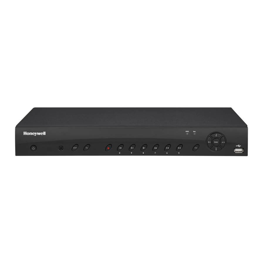
Introduction • Supports NTSC or PAL self-adaption. • Supports viewing real-time system resources information and running statistics display. • Supports log file. • Supports local GUI output and shortcut menu operation with a computer mouse. • Supports IR control using shortcut menu operation with a computer mouse. •... - Page 18 Performance Series Network Video Recorder User Guide HEN04103L/HEN08103L Table 1-1 NVR Front Panel Components Component Icon Function Name Power Button Power button. Press this button for three seconds to boot up or shut down the NVR. IR Receiver Receives the signal from the remote control.
- Page 19 Introduction Play/Pause • Reverse playback or pause mode: Click to return to normal playback mode. • Normal playback: Click to pause playback. • Pause mode: Click to resume playback. • Real-time monitor mode: Click to enter the Search interface. •...
- Page 20 Performance Series Network Video Recorder User Guide HEN04103L/HEN08103L HEN16103L/HEN32103L HEN041*3 HEN081*3 HEN161*3 Note * = storage in TB.
- Page 21 Introduction Table 1-2 NVR Back Panel Components Icon/Marker Port/Component Connection Function Name USB 2.0 Port Connect a USB 2.0 mouse. Network Port 10 M / 100 M / 1000 Mbps self- adaptive Ethernet port. Connect to a network cable. RS232 (RS- 232 Debug COM For general COM debugging, to 422)
-
Page 22: Mouse Operation
Performance Series Network Video Recorder User Guide such as an alarm. • Bi-directional communication output. • Audio output on a 1-window video monitor. • Audio output on a 1-window video playback. eSATA External eSATA External storage devices. Mouse Operation Your Network Video Recorder is optimized for mouse navigation. Use the supplied mouse to set up the DVR. -
Page 23: Remote Control Operation
Introduction Figure 1-4 On-screen Keyboard 2. Click the key corresponding to the letter/number/special character that you want to input in the text box. • To switch between lowercase and uppercase letters, click Shift. • To delete the previous character, click the key. - Page 24 Performance Series Network Video Recorder User Guide While in playback mode, use the up/down buttons to Enter Go to the default. Go Switch Mult between the multi- channel In the single- monitor mode, use the popup the PTZ control In text mode, press...
-
Page 25: Getting Started
• Mouse • Serial ATA (SATA) cable* If any of the items listed above are missing or damaged, contact your Honeywell dealer immediately. Connecting External Devices Step 1: Connect the cameras Connect the coaxial cables from the cameras to the VIDEO IN connectors (1 Vp-p, 75 ohm). -
Page 26: Typical Nvr Installation
Performance Series Network Video Recorder User Guide Step 4: Connect the Ethernet cable Connect the supplied CAT5e Ethernet cable to the network port. Connect the other end to a router on your network. Step 5: Connect audio devices (if applicable) To record audio, connect the audio sources to the AUDIO IN connectors. - Page 27 Getting Started...
- Page 28 Performance Series Network Video Recorder User Guide...
- Page 29 Getting Started...
-
Page 30: Starting And Shutting Down The Nvr
Performance Series Network Video Recorder User Guide Starting and Shutting Down the NVR Starting the NVR 1. Verify that the NVR is connected to an appropriate power source. 2. Turn on the power switch on the rear panel to start the NVR. -
Page 31: Device Initialization
Getting Started Device Initialization When the NVR has booted up, the system enters the Device Initialization window. Figure 2-2 Device Initialization – Enter Password 1. Enter the password according to the password requirements. The default username is admin. You can use the USB mouse to change the password. Click the soft keyboard button to switch the input mode between numbers and English letters;... - Page 32 Performance Series Network Video Recorder User Guide Draw the unlock patterns. You will be asked to draw two times of patterns. Make sure they are the same. 3. Click Next and the following window is displayed: Figure 2-4 Device Initialization-Password Protection Security Question: Enter the Security Questions.
-
Page 33: Reset Password
Getting Started Figure 2-6 Warning Message 2 Reset Password If you forgot the admin password, you can reset the password by answering the security questions. 1. Go to the system login interface as shown in the following figures: Figure 2-7 System Login with Unlock Pattern Figure 2-8 System Login with Password •... - Page 34 Performance Series Network Video Recorder User Guide • If you didn’t set the unlock pattern, device displays the password login window, see Figure 2-8. Click Switch User, NVR goes to general user login interface. Note The default user name is admin. Select a user from the username dropdown list and login via this user.
-
Page 35: Setting Up The Nvr With The Startup Wizard
Getting Started Setting Up the NVR with the Startup Wizard After the device initialization, the Startup Wizard opens. Figure 2-11 Startup Wizard Using the wizard, you can: • Configure general settings (device name, number, language, video standard) • Set the date and time •... - Page 36 Performance Series Network Video Recorder User Guide Figure 2-12 Startup Wizard - GENERAL For more information about configuring settings in the GENERAL window, see Configuring General System Settings on page 115. 2. Click Next to go to the TCP/IP window.
- Page 37 Getting Started Figure 2-14 Startup Wizard - Camera Registration Window For more information about configuring settings in the Camera Registration window, see Adding a Camera on page 53. 4. Click Next to go to the SCHEDULE window. Figure 2-15 Setup Wizard - SCHEDULE Window For more information about configuring settings in the SCHEDULE window, see Configuring the Video Recording Schedule on page...
-
Page 38: Setting Up Bi-Directional Communication Connection
Performance Series Network Video Recorder User Guide Figure 2-16 Setup Wizard Finished 6. Click Yes to close the wizard. Setting Up Bi-Directional Communication Connection Audio Output Device to a PC Connect: 1. Connect a microphone or pickup to the first audio input port on the NVR’s rear panel. - Page 39 Getting Started 1. Connect the microphone or the pickup to the audio input port in the PC. 2. Connect the earphone or the sound box to the audio output port on your PC. 3. Open web client and log in. 4.
-
Page 40: Viewing Live Video
Performance Series Network Video Recorder User Guide 3 Viewing Live Video This chapter contains the following sections: • About Live View on page 26. • Configuring Live View on page 29. • Controlling PTZ Cameras on page 30. About Live View Live view is the NVR’s default mode. -
Page 41: Camera Status
Viewing Live Video Camera Status Camera status icons appear at the bottom of the channel window. No video signal Video is being recorded Motion detected in scene Camera locked Camera Toolbar A camera toolbar is located at the top of each channel window. To display the toolbar, move the mouse pointer to the top of the channel window. -
Page 42: Live View Toolbar
Performance Series Network Video Recorder User Guide Live View Toolbar If enabled, the live view toolbar appears along the bottom of the live view screen. Figure 3-3 Live View Toolbar The toolbar is disabled by default. To enable it, right-click and go to Main Menu SETTING >... -
Page 43: Shortcut Menu
Viewing Live Video Open the USB Manage window. USB Manage Shortcut Menu The shortcut menu is displayed by right-clicking anywhere on the screen in live view mode. Figure 3-4 Shortcut Menu The Shortcut Menu varies according to products, refer to the actual interface of your products. -
Page 44: Controlling Ptz Cameras
Performance Series Network Video Recorder User Guide For example, to move channel 2 to the top left position occupied by channel 1, click channel 2, drag it to channel 1’s position, then release the mouse button. Controlling PTZ Cameras This section describes how to do the following: •... - Page 45 Viewing Live Video Expanded PTZ Control Panel Figure 3-6 Expanded PTZ Control Panel Table 3-4 Expanded PTZ Control Panel Name Function Configure/call PTZ functions. Preset, Tour, Pattern Enter number of PTZ function to call. Call auxiliary functions. Enable up-the-coax OSD menu configuration for non- Enter Menu PTZ camera.
-
Page 46: Configuring Ptz Connection Settings
Performance Series Network Video Recorder User Guide Figure 3-8 Expanded PTZ Control Panel Configuring PTZ Connection Settings Before you can control a PTZ camera with the NVR, you must configure the PTZ connection settings. This function is only available for... - Page 47 Viewing Live Video You can configure presets, tours, patterns, and borders using the PTZ control panel. Configuring PTZ Presets You can program preset positions for the PTZ camera. For example, you can point the camera at a specific location, such as a doorway, when an alarm event occurs. 1.
- Page 48 Performance Series Network Video Recorder User Guide Figure 3-13 Tour 4. In the Patrol No. box, enter a number for the tour. 5. Click Add Preset to add the preset to the tour. 6. Repeat steps 1 through 5 to add additional presets to the tour.
-
Page 49: Calling Presets, Tours, And Patterns
Viewing Live Video Configuring PTZ Borders You can define the left and right borders of the PTZ camera’s pan movement, or scan. 1. On the expanded PTZ control panel, click the PTZ Setting button. Figure 3-16 PTZ Setting Button 2. Select the Border tab for Border setting options. Figure 3-17 Border 3. -
Page 50: Configuring Auxiliary Settings
Performance Series Network Video Recorder User Guide Figure 3-19 Tour Button 2. Click the Tour button again to stop calling the tour. To call a pattern 1. On the expanded PTZ control panel, in the No. box, enter the number of the pattern that you want to call, and then click the Pattern button. -
Page 51: Recording Video
Recording Video 4 Recording Video This chapter contains the following sections: • Manual Recording Settings on page 37. • Automatic Recording Settings on page 37. Manual Recording Settings In live view mode, you can manually record a clip directly to a connected USB storage device. To back up recorded video to a connected USB storage device, Note please see... -
Page 52: Configuring The General Recording Settings
Performance Series Network Video Recorder User Guide Configuring the General Recording Settings In the RECORD configuration interface, you can do the following: • Select Auto/Schedule recording for the main and sub streams • Select Manual recording for the main and sub streams •... - Page 53 Recording Video Figure 4-2 Storage Schedule Settings 2. On the Record tab, in the Channel box, select the channel (camera) for which you want to configure a recording schedule. 3. In the PreRecord box, enter a time between 0 and 30 seconds. The default setting is 4 seconds.
-
Page 54: Configuring The Snapshot Recording Schedule
Performance Series Network Video Recorder User Guide 8. Click or drag the mouse in the scheduling table to set the recording period. To erase a recording period, click the eraser icon ( ) at the right of the table. Alternatively, for the day of the week that you want to configure, click the gear icon at the right of the table. - Page 55 Recording Video The POS function is only available for Note HEN081*4/HEN162*4/HEN163*4/HEN161*4/HEN322*4/ HEN323*4/HEN321*4/HEN642*4/HEN643*4. 4. At the left of the scheduling table, select the day(s) of the week for which you want to configure a recording schedule. To configure the same recording schedule for all of the days at the same time, select All.
- Page 56 Performance Series Network Video Recorder User Guide Image Size: The size is automatically selected, based on the resolution of the camera. Image Quality: Select a value between 1 and 6, with 6 being the highest quality. Interval: Select a value between 1 SPL (second per picture) and 7 SPL or click Customized to enter your own setting.
-
Page 57: Playing Back Video
Playing Back Video 5 Playing Back Video This chapter contains the following sections: • Playing Back Video on page 43. • Smart Player Playback on page 48. • Playing Back Snapshots on page 48. • Backing Up Video and Snapshots on page 49. -
Page 58: Smart Search
Performance Series Network Video Recorder User Guide 4. At the bottom of the screen, select the recording type(s) that you want to search (Regular, Alarm, Motion, Analytics, POS) or select All to search all recording types. The POS function is only available for... -
Page 59: Mark Playback
Playing Back Video Figure 5-2 Search For Activity 3. Click the Smart Search button again. Playback jumps to all the parts of the video where there is activity in that area. 4. To exit Smart Search, click the Smart Search button again. The message "Are you sure to exit smart search now?"... - Page 60 Performance Series Network Video Recorder User Guide Playback Mark During 1-window playback mode, click mark file list button , you can go to mark file list interface. Double click one mark file, you can begin playback from the mark time.
-
Page 61: Slice Playback
Playing Back Video • After you go to the mark management interface, system needs to pause current playback. System resume playback after you exit mark management interface. Note • If the mark file you want to playback has been removed, system begins playback from the first file in the list. -
Page 62: Smart Player Playback
Performance Series Network Video Recorder User Guide • The slice playback is for 1-window playback mode. • System supports 1/4/8/16-split mode. Slight difference may be found here. The 4-channel series product supports 4-split mode. The 8-channel series product support 8-split mode. -
Page 63: Backing Up Video And Snapshots
Playing Back Video 4. In the calendar area, click the date(s) that you want to search. Dates with saved snapshots are solid orange. 5. Below the calendar, select the camera(s) that you want to watch, and select the stream. 6. Click the File List button to display the list of search results. 7. - Page 64 Performance Series Network Video Recorder User Guide Figure 5-7 Search Results Alternatively, during video playback, in the video clip time field, enter the desired start time and end time, and then click the Save button. Figure 5-8 Playback Save/Backup Button The Backup window opens, displaying the selected video file/clip.
-
Page 65: To Back Up From Outside Of The Playback Interface
Playing Back Video Figure 5-10 Backup - Browse USB Storage Window 6. Click Start to back up the file(s). If the backup is successful, the message "Backup finished" appears. To back up from outside of the playback interface 1. Insert a USB storage device (such as a USB flash drive) into one of the USB ports on the NVR. - Page 66 Performance Series Network Video Recorder User Guide Figure 5-12 File Back to USB Device Window 3. In the Backup window, configure the following settings: Type: Select the file type for which you want to search. To search for snapshots, select PIC, as All means all Note video files (excluding snapshots).
-
Page 67: Configuring Camera Settings
Configuring Camera Settings 6 Configuring Camera Settings This chapter contains the following sections: • Adding a Camera on page 53. • Configuring Camera Image Settings on page 55. • Configuring Snapshot Settings on page 57. • Configuring Encoding Settings on page 58. •... -
Page 68: Adding A Camera Manually
Performance Series Network Video Recorder User Guide Click to select the found camera. Click Add to add the found device to the Added Device list. If the NVR fails to display the model name of a found device, Note click Device Search to rediscover the online devices. The model name should appear in the Found Devices list. -
Page 69: Configuring Camera Image Settings
Configuring Camera Settings Configuring Camera Image Settings You can configure camera settings only if you have connected your IP cameras via a Private Protocol. If you have connected Note via a Private Protocol, then the Camera settings will be available. If you have connected your IP cameras via other protocols, then the Camera settings will not be available. - Page 70 Performance Series Network Video Recorder User Guide Note If this value is too high, then the video can become hazy. Contrast: Adjusts monitor contrast. Choosing a higher value increases the contrast. Select from 0 to 100. The recommended range is between 40 and 60. The default value is If this value is too low, then the video can become hazy.
-
Page 71: Configuring Snapshot Settings
Configuring Camera Settings • Outdoor: The white balance threshold is set to outdoor mode. Natural: The white balance threshold is set to natural mode. Street Lamp: The white balance threshold is set to street lamp mode. • Manual: You can manually set the gain for the red/blue channel. The value ranges from 0 to 100. -
Page 72: Configuring Encoding Settings
Performance Series Network Video Recorder User Guide Configuring Encoding Settings 1. Go to Main Menu Setting CAMERA Encode Encode Mode, the following window is displayed: Figure 6-4 Camera Encoding Settings Tab 2. On the Encode tab, in the Channel box, select the camera that you want to configure. -
Page 73: Configuring The Text Overlay
Configuring Camera Settings After changing smart code, please reboot network camera and some network camera functions (such as IVS, ROI, SVC, lobby Note mode and etc.) becomes null. Please think twice before the operation. Resolution: Set the primary stream resolution to one of the following options in the drop- down list. -
Page 74: Changing A Camera Name
Performance Series Network Video Recorder User Guide Figure 6-5 Camera Text Overlay Setting Tab 2. In the Channel box, select the camera that you want to configure. 3. To set the time display, next to Time Display, select the Monitor check box, and then click Setup. - Page 75 Configuring Camera Settings Figure 6-6 Camera Name Settings Window 2. Select Local or Remote in the Camera Name dropdown list. Local: Select it to change the channel name of NVR. Remote: Select it to change the channel name of IPC via NVR. 3.
-
Page 76: Configuring Network Settings
Performance Series Network Video Recorder User Guide 7 Configuring Network Settings This chapter contains the following sections: • Configuring TCP/IP Settings on page 62. • Configuring Port Settings on page 63. • Configuring Wireless Connection Settings on page 65. •... -
Page 77: Configuring Port Settings
Configuring Network Settings 2. Click to edit the Ethernet card as shown in the following figure: Figure 7-2 Edit Ethernet Card 3. Select a net mode. 4. In the IP Version box, select IPv4 or IPv6, depending on the Internet protocol that you want to use. - Page 78 Performance Series Network Video Recorder User Guide Figure 7-3 Network Port Settings Window 2. On the Connection page, you can configure the following settings: Max Connection: Select a value between 1 and 128. The default setting is 20. TCP Port: Select a value between 1025 and 65535. The default setting is 37777.
-
Page 79: Configuring Wireless Connection Settings
Configuring Network Settings Configuring Wireless Connection Settings This function is only available for Note HEN081*4/HEN162*4/HEN163*4/HEN161*4/HEN322*4/HEN323* 4/HEN321*4/HEN642*4/HEN643*4. To manage Wi-Fi connections 1. Go to Main Menu Setting NETWORK WIFI, the following window is displayed: Figure 7-4 Network WIFI Settings Window 2. - Page 80 Performance Series Network Video Recorder User Guide To configure 3G wireless connections This function is only available for Note HEN081*4/HEN162*4/HEN163*4/HEN161*4/HEN322*4/HEN323* 4/HEN321*4/HEN642*4/HEN643*4. 1. Go to Main Menu Setting NETWORK 3G, the following window is displayed: Figure 7-5 Network 3G Window 2.
-
Page 81: Configuring Pppoe Settings
Configuring Network Settings Configuring PPPoE Settings 1. Go to Main Menu Setting NETWORK PPPoE, the following window is displayed: Figure 7-6 Network PPPoE Settings Window 2. On the PPPoE page, select the Enable check box to enable a PPPoE network connection. 3. -
Page 82: Configuring Email Settings
IP address of your DDNS service provider. Domain Mode: If DDNS Type is set to Honeywell DDNS, click Default Domain to use the default domain name or click Custom Domain Name to create your own domain name. - Page 83 Configuring Network Settings Figure 7-8 Network Email Settings Window 2. On the EMAIL page, select the Enable check box to enable email notifications for alarm events. 3. Configure the following settings: SMTP Server: Enter the SMTP server address of the sender’s email account. Port: The default TCP/IP port used for SMTP is 25.
-
Page 84: Configuring Upnp Settings
Performance Series Network Video Recorder User Guide Configuring UPnP Settings The Universal Plug and Play (UPnP) protocol is used to map the relationship between the LAN and the WAN. 1. Go to Main Menu Setting NETWORK UPnP, the following window is displayed: Figure 7-9 Network UPnP Settings Window 2. -
Page 85: Configuring Snmp Settings
Configuring Network Settings 1. Go to Main Menu Setting NETWORK Sync Time Right, the following window is displayed: Figure 7-10 Sync Time Right Settings Window 2. Select the Enable check box to enable Sync Time Right. 3. Next to the Enable check box, click Trusted Sites. 4. - Page 86 Performance Series Network Video Recorder User Guide Figure 7-11 Network SNMP Settings Window 2. On the SNMP page, select the Enable check box to enable SNMP. 3. Configure the following settings: Version: Select the check boxes of the SNMP version that you are using.
-
Page 87: Configuring Multicast Settings
Configuring Network Settings Configuring Multicast Settings Multicast allows for simultaneous real-time monitoring of live video from the NVR at multiple remote locations over the network. 1. Go to Main Menu Setting NETWORK Multicast, the following window is displayed: Figure 7-12 Network Multicast Settings Window 2. -
Page 88: Configuring Alarm Center Settings
Performance Series Network Video Recorder User Guide 3. Enable the auto register function in the NVR. The NVR should now be able to automatically register to the proxy server. Configuring Alarm Center Settings 1. Go to Main Menu Setting NETWORK Alarm Center, the following window is... -
Page 89: Configuring Switch Settings
Configuring Network Settings Configuring Switch Settings This function is only available for HEN081*4/HEN162*4/HEN163*4/HEN161*4/HEN322*4/HEN323* Note 4/HEN321*4/HEN642*4/HEN643*4/HEN041*3/HEN081*3/HEN16 1*3. You can change the IP Address, Subnet Mask, and Default Gateway for setting the PoE switch settings. 1. Go to Main Menu Setting NETWORK Switch, the following window is displayed: Figure 7-14 Network Switch Settings Window 2. - Page 90 Performance Series Network Video Recorder User Guide Figure 7-15 Network P2P Settings Window 2. Check the Enable check box. 3. Using a mobile device running the HonView Touch app, select to add a device. 4. Use the mobile device’s camera to view the QR code on the P2P screen.
-
Page 91: Configuring Event Settings
Configuring Event Settings 8 Configuring Event Settings This chapter contains the following sections: • Configuring Motion Detection Settings on page 79. • Configuring Video Loss Settings on page 83. • Configuring Video Tampering Settings on page 84. • Configuring Scene Change Settings on page 85. - Page 92 Performance Series Network Video Recorder User Guide Figure 8-23 People Counting Rule In the Name field, enter the name of rule. In the Direction field, select the direction of people counting. You can select A->B or B->A, the arrow direction always means the entrance direction.
-
Page 93: Configuring Motion Detection Settings
Configuring Event Settings You also need to set the alarm recording period. Go to Storage Schedule to configure the current channel for scheduled Note alarm recording. See Configuring the Video Recording Schedule on page PTZ Activation: Select the check box to activate PTZ functions, and then click Set. In the PTZ Activation window, for each PTZ camera, select the preset, tour, or pattern that you want to be called when the people counting event occurs, and then click OK. - Page 94 Performance Series Network Video Recorder User Guide Figure 8-1 Motion Detection Settings Tab 2. On the Motion Detection tab, in the Channel box, select the channel (camera) to configure for motion detection. 3. Select the Enable check box to enable motion detection for the selected channel.
-
Page 95: To Set Up Motion Detection Periods
Configuring Event Settings 6. By default, motion detection Region1 covers the whole screen. • To disable motion detection in part of the image, drag the mouse over the area of the image that you want to exclude. The areas not covered by red boxes are not sensitive to motion. -
Page 96: To Set Up Motion Detection Event Actions
Performance Series Network Video Recorder User Guide Figure 8-4 Motion Detection Period Configuration Window Set up to six periods in the day when you want the motion detection settings for the selected channel to be active. a. Select the check box next to each configured period to enable it. -
Page 97: Configuring Video Loss Settings
Configuring Event Settings 2. On the Motion Detection tab, select the actions that you want the system to initiate when a motion detection event occurs: Anti-Dither: Set an anti-dither time. The value ranges from 5 to 600s. The anti-dither time refers to the alarm signal lasts time. -
Page 98: Configuring Video Tampering Settings
Performance Series Network Video Recorder User Guide Figure 8-6 Video Loss Configuration Tab 2. On the Video Loss tab, in the Channel box, select the channel (camera) for which you want to configure video loss detection settings. 3. Select the Enable check box to enable video loss detection for the selected channel. -
Page 99: Configuring Scene Change Settings
Configuring Event Settings 2. On the Tampering tab, in the Channel box, select the channel (camera) for which you want to configure video tampering detection settings. 3. Select the Enable check box to enable video tampering detection for the selected channel. -
Page 100: Configuring Smart Plan Settings
Performance Series Network Video Recorder User Guide Configuring Smart Plan Settings Smart plan is a master switch for the intelligent analytics such as Face Detection and People Counting. The device intelligent functions can be valid after smart plan is enabled. -
Page 101: Configuring Network Event Settings
Configuring Event Settings Figure 8-10 HDD Abnormality Configuration Tab 1. On the HDD tab, in the Event Type box, select the event type that you want to configure settings for: No HDD, HDD Error, No Space. If you select the No Space event, you can specify how low the HDD space will get before triggering the event in the Less Than field. -
Page 102: Configuring Username Settings
Performance Series Network Video Recorder User Guide Figure 8-11 Network Abnormality Configuration Tab 2. On the Network tab, in the Event Type box, select the event type for which you want to configure settings: Disconnect, IP Conflict, MAC Conflict. 3. Select the Enable check box to enable network error detection for the selected event type. -
Page 103: Configuring Alarm Input Settings
Configuring Event Settings Figure 8-12 Username Abnormality Configuration Tab 2. On the Username tab, in the Event Type box, select the event type for which you want to configure. 3. Select the Enable check box to enable username error detection for the selected event type. - Page 104 Performance Series Network Video Recorder User Guide Figure 8-13 IPC External Alarm Configuration Tab 2. On the IPC Ext tab, select the channel to configure the external alarm settings from the drop-down menu. 3. Select the Enable check box to enable alarm detection of the selected alarm input.
- Page 105 Configuring Event Settings Figure 8-15 Period Window a. Set up to six periods in the day when you want alarm detection for the selected alarm input to be active. b. Select the check box next to each configured period to enable it. c.
-
Page 106: Configuring Ipc Offline Alarm Events
Performance Series Network Video Recorder User Guide You also need to set the alarm recording period. Go to Storage Schedule to configure the current channel for scheduled Note Configuring the Video Recording alarm recording. See Schedule on page 38. -
Page 107: Configuring Network Alarm Inputs
Configuring Event Settings Go to Main Menu SETTING EVENT ALARM Local. Figure 8-17 Local Alarm Configuration Tab To configure local alarm inputs, follow the same steps as for configuring IPC External Alarm inputs, on page 89. Configuring Network Alarm Inputs Network alarms are alarm signals from the network. -
Page 108: Configuring Heat Map
Performance Series Network Video Recorder User Guide Figure 8-19 Remote Alarm Configuration Tab To configure remote alarm input actions, follow the same steps as for configuring IPC External Alarm inputs event actions, see To set up alarm input event actions... -
Page 109: Configuring Face Detection Settings
Configuring Event Settings 2. Select the Channel to configure for heat mapping from the drop-down menu and check the Enable check box. 3. To set the periods when heat mapping is active, next to Period, click Set, and then follow the steps listed in To set up motion detection periods on page 81. -
Page 110: Configuring Audio Detection Settings
Performance Series Network Video Recorder User Guide Record Channel: Select the channel(s) that you want to record when the alarm is triggered. In the Delay box, specify the amount of time (10–300 s) to delay recording after a face detection event is triggered. - Page 111 Configuring Event Settings Input Abnormal: Detects if the audio input changes from the "normal" audio that is typically generated at the site. Intensity Change: Detects if the audio intensity changes, meaning the volume level becomes stronger than the typical levels. 3.
-
Page 112: Configuring People Counting
Performance Series Network Video Recorder User Guide Log: Select the check box to enable logging of the audio detection event. Voice Prompts: Select the check box to enable the playing of a voice prompt audio file when an audio detection event is triggered. Use the File Name drop-down arrow to select the audio file to play for the events. - Page 113 Configuring Event Settings Figure 8-23 People Counting Rule In the Name field, enter the name of rule. In the Direction field, select the direction of people counting. You can select A->B or B->A, the arrow direction always means the entrance direction. Click to set up the target size.
-
Page 114: Configuring Alarm Outputs
Performance Series Network Video Recorder User Guide You also need to set the alarm recording period. Go to Storage Schedule to configure the current channel for scheduled Note alarm recording. See Configuring the Video Recording Schedule on page 38. -
Page 115: Configuring Pos Settings
Configuring Event Settings 4. Click Apply to save your changes, and then click OK. Configuring POS Settings This function is only available for Note HEN081*4/HEN162*4/HEN163*4/HEN161*4/HEN322*4/HEN323* 4/HEN321*4/HEN642*4/HEN643*4. Use the POS settings screen to setup a connection to a point of sales device, such as a cash register, to enable POS info to be synchronized with video data. - Page 116 Performance Series Network Video Recorder User Guide Figure 8-26 Privacy Set 6. Other parameters are described in the following section: Connect Type: Select the type of connection to the POS device. Click Setup to enter the connection details for Source IP and Port, and Destination IP and Port. Click OK to confirm.
-
Page 117: Pos Type Supported By Nvr
Configuring Event Settings POS Type Supported by NVR NVR supports the following types of POS: Table 8-1 POS Type Supported by NVR Area POS Brand POS Controlling Software North Eastern POSNET PXE_Sender_ENG Europe Thermal HD 2.01 Poland North Eastern Mistral;Eltrade;Microinvest Software supplied by the Europe manufacturer... -
Page 118: Configuring Storage Settings
Performance Series Network Video Recorder User Guide 9 Configuring Storage Settings This chapter contains the following sections: • Configuring the Basic Settings on page 104. • Configuring the Recording Schedule on page 105. • Configuring HDD Manager Settings on page 107. -
Page 119: Configuring The Recording Schedule
Configuring Storage Settings Auto Delete Old Files: Select Never or Customized. If Customized is selected, in the Days Ago box, enter the amount of time to elapse before the files are automatically deleted. Configuring the Recording Schedule Configuring the Video Recording Schedule 1. -
Page 120: Configuring The Snapshot Recording Schedule
Performance Series Network Video Recorder User Guide MD&Alarm: The motion detection and alarm schedule is indicated by a blue bar. Analytics: The video analytics schedule is indicated by an orange bar. POS: The POS schedule is indicated by a light blue bar. -
Page 121: Configuring Hdd Manager Settings
Configuring Storage Settings Figure 9-3 Snapshot Schedule Settings 2. On the Snapshot tab, in the Channel box, select the channel (camera) for which you want to configure a snapshot schedule. 3. At the top of the scheduling table, select the check box(es) of the recording type(s) that you want to schedule: Regular: The regular recording schedule is indicated by a green bar. -
Page 122: Configuring Ftp Settings
Performance Series Network Video Recorder User Guide Figure 9-4 HDD Manager Window Name: The HDD name. Physical Position: Indicates which hard drive slot the HDD currently occupies. Type: The HDD type (read-write or read-only). HDD Group: The HDD group that the hard drive belongs to. - Page 123 Configuring Storage Settings Figure 9-5 Network FTP Window 2. On the FTP page, click the Enable check box to enable uploading images to an FTP server. 3. Configure the following settings: Host IP: Enter the address of the FTP server. Port: Enter the port of the FTP server.
-
Page 124: Configuring Hdd Advanced Settings
Performance Series Network Video Recorder User Guide Configuring HDD Advanced Settings Configuring Main Stream Settings Here, you can assign the main stream to a particular HDD group. 1. Go to Main Menu SETTING STORAGE Advanced Main Stream. -
Page 125: Configuring Nas Storage
Configuring Storage Settings Figure 9-7 Snapshot Storage Configuration Tab 2. You can set the HDD group for all channels or set each channel individually: • Select a HDD group from the drop-down Set All Channels menu. Click All to apply the parameter settings to all channels. -
Page 126: Configuring Nas Manager
Performance Series Network Video Recorder User Guide Enable: Select the Enable check box to enable the NAS storage function. IP Address: Enter the IP address of the NAS Storage. Mount Point: Enter the path of the NAS Storage. Configuring NAS Manager Go to Main Menu ... -
Page 127: Configuring Hdd Detect Settings
Configuring Storage Settings Figure 9-10 Recording Storage Configuration Window 1. On the Record window, select the record types (Auto, Manual, Off) that you want to enable on each channel for both the main stream and secondary streams. 2. Under Snapshot, enable or disable snapshot recording on each channel. 3. -
Page 128: Hdd Detection Reporting
Performance Series Network Video Recorder User Guide Figure 9-11 HDD Manual Detection Screen HDD Detection Reporting Hard Disk Drives detection results are compiled on the detect report screen for easy reference. 1. Go to Main Menu SETTING STORAGE HDD Detect Detect Report. -
Page 129: 10 Configuring System Settings
Configuring System Settings 10 Configuring System Settings This chapter contains the following sections: • Configuring General System Settings on page 115. • Configuring Display Settings on page 119. • Configuring RS232 Settings on page 122. • Configuring PTZ Settings on page 123. •... -
Page 130: Configuring Date And Time Settings
Performance Series Network Video Recorder User Guide Figure 10-1 General Configuration Tab 2. On the General tab, configure the following settings: Device Name: Enter a device name for the NVR. Device No.: Enter a device number for the NVR. Language: Set the language of the user interface. - Page 131 Configuring System Settings Figure 10-2 Date and Time Configuration Tab 2. On the Date&Time tab, configure the following settings: Date Format: Select the date format that you want to use for the system time: YYYY MM DD, MM DD YYYY, or DD MM YYYY. Time Format: Select the time format that you want to use for the system time: 24-Hour or 12-Hour.
-
Page 132: Configuring Holiday Settings
Performance Series Network Video Recorder User Guide To synchronize the system time with the Network Time Protocol (NTP) 1. Ensure that the NVR is connected to the Internet. 2. Go to Main Menu SETTING SYSTEM GENERAL Date&Time. -
Page 133: Configuring Display Settings
Configuring System Settings Figure 10-4 Add Holidays Window 3. In the Holiday Name box, enter the name of the holiday that you want to add. 4. Set Repeat Mode to Once or Always. If you want the NVR to recognize a particular day of the week as Note a holiday year-round (for example, every Friday), set Repeat Mode to Always. - Page 134 Performance Series Network Video Recorder User Guide Figure 10-5 Display Configuration Tab 2. On the Display tab, configure the following settings: Transparency: Set the transparency of the graphical user interface (GUI) to a value between 0 and 100, with 0 being totally opaque and 100 being totally transparent.
-
Page 135: Configuring Tour Settings
Configuring System Settings Configuring Tour Settings In a tour, the NVR cycles through different channel views. You can specify which views and cameras you want to appear in the tour. 1. Go to Main Menu SETTING SYSTEM DISPLAY Tour. Figure 10-6 Tour Configuration Tab 2. -
Page 136: Configuring Custom Split Settings
Performance Series Network Video Recorder User Guide 7. Click Apply to save your settings. 8. If you want to save your settings and exit the SETTING menu, click OK. Configuring Custom Split Settings This function is only available for Note HEN081*4/HEN162*4/HEN163*4/HEN161*4/HEN322*4/HEN323* 4/HEN321*4/HEN642*4/HEN643*4. -
Page 137: Configuring Ptz Settings
Configuring System Settings Figure 10-8 RS232 Configuration Window 2. Configure the following settings: Function: Select Console or Adapter, depending on the type of RS232 device that you have connected to the NVR. Baud Rate: Select a value between 1200 and 115200. The default setting is 115200. Data Bit: Select a value between 5 and 8. -
Page 138: Configuring Voice Prompt Settings
Performance Series Network Video Recorder User Guide 1. Go to Main Menu SETTING SYSTEM Broadcast. Figure 10-9 Broadcast Configuration Window 2. Click Add Group to add a new broadcast group. Enter a Group Name and select the channels to be part of the group. -
Page 139: Configuring Voice Prompt Schedules
Configuring System Settings Figure 10-10 Voice Prompt File Configuration Window 2. Click Add to add a new audio file for Voice Prompts. You must have a connected USB device with audio files saved to it. 3. Double-click on folders to navigate to the new voice prompt file, select the check box for the file(s) you want to add and click Import. -
Page 140: Configuring Account Settings
Performance Series Network Video Recorder User Guide Figure 10-11 Voice Prompt Schedule Configuration Window 4. Click Apply to save your settings. 5. If you want to save your settings and exit the SETTING menu, click OK. Configuring Account Settings You can add, edit, or delete user accounts. By default, the NVR has an admin user account and a default user account. - Page 141 Configuring System Settings Figure 10-12 User Account Configuration Tab 2. On the User tab, click Add User. The Add User page opens. Figure 10-13 Add User Window 3. On the Add User page, configure the following settings for the new user: Username: Enter a user name for the account.
- Page 142 Performance Series Network Video Recorder User Guide By default, the user group is set up to allow a new user to monitor live video from all cameras, play back recorded video from all cameras, control PTZ cameras, view information, Note manually control the NVR, back up files, and adjust color settings.
-
Page 143: Configuring Account Security Questions
Configuring System Settings Figure 10-14 Group Configuration Tab 2. On the Group tab, click Add Group. 3. On the Add Group page, enter a name for the group in the Group Name box, enter a description of the group in the Memo box, and then assign user permissions on the Authority tabs. -
Page 144: Configure Onvif User
Performance Series Network Video Recorder User Guide In case that the admin password is lost or forgotten, you can setup security questions for the admin account that can be answered if the password is ever forgotten. 1. Go to Main Menu SETTING SYSTEM ACCOUNT Secure Question. -
Page 145: Configuring Security Settings
Configuring System Settings The configuration for ONVIF User is very similar to the configuration for User, see Managing User Accounts and Groups on page for more information. Configuring Security Settings To allow specific sites to access the NVR 1. Go to Main Menu SETTING SYSTEM Security. Figure 10-17 System Security Settings Window 2. -
Page 146: Configuring Automatic Maintenance Settings
Performance Series Network Video Recorder User Guide 3. Next to the Enable check box, click Blocked Sites. 4. Click Add. 5. To add a single IP address, select IP Address from the drop-down list and enter the IP address of the site that you want to block and click OK. -
Page 147: To Export A System Configuration
Configuring System Settings To export a system configuration 1. Go to Main Menu SETTING SYSTEM IMP/EXP. 2. Insert a USB storage device (such as a USB flash drive) into one of the USB ports on the NVR. The Find USB device dialog box opens. Figure 10-19 Find USB Device Window 3. -
Page 148: To Format An External Usb Storage Device
Performance Series Network Video Recorder User Guide 4. Restart the NVR to apply the new settings. To format an external USB storage device 1. Go to Main Menu SETTING SYSTEM IMP/EXP. 2. Insert a USB storage device (such as a USB flash drive) into one of the USB ports on the NVR. -
Page 149: Upgrading The Nvr
Configuring System Settings 3. Click Apply to save your settings. 4. If you want to save your settings and exit the SETTING menu, click OK. To return the NVR to its factory default settings, click Factory Note Reset. Upgrading the NVR You can upgrade the system firmware locally at the NVR. - Page 150 Performance Series Network Video Recorder User Guide Figure 10-24 Upgrade Window 5. Select the firmware file from the file list, and then click Start.
-
Page 151: 11 Viewing Information
Viewing Information 11 Viewing Information This chapter contains the following sections: • Viewing System Information, on page • Viewing Event Information, on page • Viewing Network Information, on page • Viewing Log Information, on page Viewing System Information In the system information interface you can view the following: •... -
Page 152: Viewing Recording Information
Performance Series Network Video Recorder User Guide x indicates there is an error. - indicates that there is no HDD. ? indicates that a HDD is damaged. Device Name: Shows the name you have given the device. Physical Position: Describes the hard drive bay where the hard drive is installed. -
Page 153: Viewing Data Stream Information
Viewing Information Figure 11-3 Recording Information Window On the Record Info page, you can view the device name as well as the start and end times for recorded video. Viewing Data Stream Information Go to Main Menu INFO SYSTEM BPS. Figure 11-4 BPS Information Window On the BPS page, you can view the current video data stream rates and resolutions for each channel. -
Page 154: Viewing Event Information
Performance Series Network Video Recorder User Guide Figure 11-5 Version Information Window On the VERSION page, you can view the number of channels, number of alarm inputs and outputs, system version number, build date, web and ONVIF versions, and serial number. -
Page 155: Viewing Heat Map Information
Viewing Information Viewing Heat Map Information This function is only available for Note HEN081*4/HEN162*4/HEN163*4/HEN161*4/HEN322*4/HEN323* 4/HEN321*4/HEN642*4/HEN643*4. Go to Main Menu INFO EVENT Heat Map. Figure 11-7 Heat Map Information Window On the Heat Map page, you can search and export the heat map information. To search the heat map information, select a channel, start time and end time, and then click Search. -
Page 156: Viewing Network Load Information
Performance Series Network Video Recorder User Guide Figure 11-8 Viewing Online Users Every five seconds, the NVR system detects newly added or Note dropped users, and updates the list of online users. To block an online user 1. Go to Main Menu INFO NETWORK ONLINE USERS . -
Page 157: Viewing Network Test Information
Viewing Information Figure 11-9 Viewing Network Load On the Load page, you can view the network device name, MAC address, status (Succeed or Failed), device IP address, network type, the maximum transmission unit (MTU), send speed, and receive speed. Viewing Network Test Information 1. -
Page 158: Viewing Log Information
Performance Series Network Video Recorder User Guide 3. Insert a USB storage device (such as a USB flash drive) into one of the USB ports on the NVR. 4. On the Test page, under Network Sniffer Packet Backup, click Refresh. The connected USB storage device should appear in the Device Name box. - Page 159 Viewing Information Figure 11-12 Find USB Device Window 2. In the Find USB device dialog box, click Log Backup. 3. On the Log page, click Backup. The log file (FileLog.txt) is located in a folder named Log_[YYYYMMDDhhmmss] on your storage device.
-
Page 160: 12 Web Client Operation
Performance Series Network Video Recorder User Guide 12 Web Client Operation This chapter describes how to access Honeywell’s Performance Series Network Video Recorder remotely using a browser-based web client. This chapter is intended for remote users of the NVRs. Logging In This chapter includes: •... -
Page 161: Logging In
Web Client Operation • The current NVR supports various browsers such as Apple Safari and Mozilla Firefox. The NVR supports multiple-channel monitoring (depending on your model) on an Apple PC. Logging In 1. Open a Web browser window. These instructions were created using IE. You can use Internet Explorer (IE), Note Safari, or FireFox. - Page 162 Performance Series Network Video Recorder User Guide Figure 12-2 Security Problem 3. Click Continue to this website (not recommended). The following window is displayed: Figure 12-3 Enter Password 4. Enter new password and confirm password. Click Next and the following window is...
- Page 163 Web Client Operation Figure 12-5 Warning Message 1 If you upgrade the firmware from previous version to this version (20190129) and if you uncheck Email and Security Question in the previous version, it will display the following message after the system reboot. Figure 12-6 Warning Message 2 5.
-
Page 164: Main Window
Performance Series Network Video Recorder User Guide Figure 12-8 Web Service Login Window 6. Enter your username and password, then click Login. A message pops up asking if you want to install controls. Figure 12-9 Controls Installation Popup Message 7. Click the message and the following message is displayed: Figure 12-10 Run Plugin Message 8. - Page 165 Web Client Operation Figure 12-12 Main Window Section 1: Function Buttons Figure 12-13 Main Window Function Tabs There are six function tabs: • Preview: You are currently in the Preview (Live) mode, where you can see all these tabs. • Playback: See Playback on page...
- Page 166 Performance Series Network Video Recorder User Guide Section 2: Monitor Channels and Function Buttons Figure 12-14 Monitor Channels Section and Function Buttons Monitor Channels The Monitor Channels section displays monitor channels that are successfully connected to the NVR. Left-click to select a channel for viewing.
- Page 167 Web Client Operation Click to enable bi-directional communication. panel Click in the control on the right to select the bi-directional communication mode. There are four options for the communication mode: DEFAULT, G711a, G711u, and PCM. Figure 12-17 Talk Mode Options After you enable bi-directional communication, if the audio input port that goes from the device to the client end is using the first channel audio input port, Note...
- Page 168 Performance Series Network Video Recorder User Guide Figure 12-19 Local Play - Select a File Interface 2. Select a file, then click Open. A media player opens and plays the selected video. Section 3: PTZ Control Panel, Image and Alarm Configuration Panels...
-
Page 169: Logging Out
Web Client Operation Vertical Click to configure vertical Synchronization synchronization. Single-channel Click to switch to single channel Window viewing. Multi-channel Click to switch to different viewing Windows window configurations. Custom Split Select the window split mode that you set in the Custom Split window. See Custom Split Configurations on page 218. -
Page 170: Live Viewing
Performance Series Network Video Recorder User Guide • A description of the NVR web client. • Descriptions of image/relay output settings, including image settings. • Descriptions of the Information available for viewing in live view, including system version, log, connection log, and online user information. -
Page 171: Image/Relay-Out Settings
Web Client Operation Click this button to change the camera display mode to Fisheye mode. This display mode is only supported by Fisheye Mode fisheye cameras. See your Fisheye camera manual for more information. Click this button and then left drag the mouse in the zone to zoom in. -
Page 172: Information
Performance Series Network Video Recorder User Guide Adjusts the monitor’s video hue. Adjusts the monitor’s video hue. To return the NVR system to default settings, click Reset. Note All of these configurations apply to the Web Viewer only. Information Version 1. - Page 173 Web Client Operation Figure 12-24 Log Configuration Interface Table 12-5 Log Configurations Configuration Description Start Time Set a start time for the log. End Time Set an end time for the log. Select from System, Config Operation, Storage, Alarm, Type Record Operation, Account, Clear Log, Playback, Connection, and All.
- Page 174 Performance Series Network Video Recorder User Guide Figure 12-25 Online User Configuration Interface You can view the user name, group name, IP address, and login time of all online users. Heat Map On the Heat Map page, you can search and export the heat map information.
-
Page 175: Configuration
Web Client Operation Figure 12-27 HDD Interface 2. Refer to the following table to interpret the HDD information: Table 12-6 HDD Information Device Name Shows the name you have given the device. Physical Position Describes the hard drive bay where the hard drive is installed. Free Space Indicates the amount of free space remaining on the HDD. -
Page 176: Camera Setup
Performance Series Network Video Recorder User Guide Camera Setup You can add IP cameras to the NVR either by automatically discovering and adding the camera or by manually entering the camera details to add the camera. Adding a Camera by Searching 1. - Page 177 Web Client Operation Figure 12-29 Manually Adding a Camera Window Table 12-7 Manual Add Parameter Function Manufacturer Select the manufacturer that applies to your camera from the list. IP Address Enter the IP address for the camera. TCP Port Enter the TCP port for the camera. (Optional) Username Enter a username.
- Page 178 Performance Series Network Video Recorder User Guide The NVR automatically defaults to selecting channel 1 when you navigate between configuration interfaces. For example, if you have selected channel 3 on the Motion Detection configuration interface, and then navigate to the...
- Page 179 Web Client Operation Note The video might become washed out if you select a high brightness value. Adjusts monitor window contrast. Select from 0 to 100. The default setting is 50. The recommended range is 40 to 60. The higher the value, the higher the contrast between light and dark elements in the image.
- Page 180 Performance Series Network Video Recorder User Guide Street Lamp: The white balance threshold is set to street lamp mode. Manual: You can manually set the gain for the red/blue channel. The value ranges from 0 to 100. Sets the camera color and the B/W mode switch. Day&Night Modes: Colorful: The camera outputs video in color.
- Page 181 Web Client Operation The NVR system supports active control frame function (ACF), which allows you to record in different frame rates. For example, you can use a high frame rate to record important events, and configure a lower frame rate for recording scheduled events. ACF allows you to set different frame rates for motion detection recording and alarm recording.
- Page 182 Performance Series Network Video Recorder User Guide Table 12-10 Snapshot Settings Setting Description Channel Select a channel. Select from two modes: Timing (scheduled) and Trigger. Timing: the snapshot is available during the period you specify. Mode Trigger: the snapshot is available only when a motion detection alarm, tampering alarm, local activation, or other alarm occurs.
- Page 183 Web Client Operation Enable this function so that the system overlays channel information in the video window. Channel Display Use the mouse to drag the channel display into position. You can see the channel on the live WEB video or the playback video. Enable this function so that the system overlays time information in the video window.
-
Page 184: Network Setup
Performance Series Network Video Recorder User Guide Figure 12-35 Camera Name Configuration Interface 2. Click the text box of the channel that you want to rename and enter the new channel name. Camera Name: Select it to change the channel name of IPC via NVR. - Page 185 Web Client Operation 2. Click the Edit icon for the Ethernet connection that you want to modify. The Edit screen opens. Figure 12-37 Edit TCP/IP Screen 3. Make any changes to the TCP/IP settings as needed, and then click OK. Table 12-12 TCP/IP Configurations Configuration Description...
- Page 186 Performance Series Network Video Recorder User Guide For the IPv6 version IP address, the Preferred DNS and Alternate DNS shall be no Note more the 128 digits. They also cannot be left blank. Configuring the Ports Go to SETUP NETWORK PORTPORT. Make any changes to the Port settings, as needed, and then click OK to save the settings.
- Page 187 Web Client Operation Configuring HTTPS With these settings, you can ensure that the PC successfully logs in through HTTPS to guarantee communication data security. This reliable and stable technology can secure user information and device safety. Figure 12-39 HTTPS Configuration Interface If you have changed the device’s IP, then you’ll need to implement the server Note certificate again.
- Page 188 Performance Series Network Video Recorder User Guide Open the Login interface through the browser. See Login Configurations on page 177. Creating a Server Certificate Follow these steps if this is the first time you are using this function. to open the Create Server Certificate window.
- Page 189 Web Client Operation Figure 12-42 Certificate Window Click Install Certificate to open the Certificate Import Wizard. Figure 12-43 Certificate Import Wizard Click Next to open the Certificate Store window.
- Page 190 Performance Series Network Video Recorder User Guide Figure 12-44 Certificate Import Wizard - Certificate Store Window Select a location for the certificate. Click Next to complete the process. A message appears to let you know the process is complete. Figure 12-45 Certificate Import Wizard - Completion Message Click Finish, and a security warning pops up.
- Page 191 Web Client Operation Figure 12-47 Certificate Import - Confirmation Message Viewing and Setting the HTTPS Port Go to SETUP NETWORK Port. Figure 12-48 Port Interface Login Configurations Open the browser, then enter https://xx.xx.xx.xx:port, where xx.xx.xx.xx is your device’s IP or domain name.
- Page 192 Performance Series Network Video Recorder User Guide Figure 12-49 Wifi Configuration Interface Click to enable Wifi. Double-click the name of a wireless device to connect to it. Click OK to save your settings. Note Click Refresh to update the list of wireless network information.
- Page 193 Web Client Operation Figure 12-50 3G Configuration Interface Table 12-14 3G Configurations Configuration Description Select a 3G network type to distinguish this 3G module from different WLAN Type ISPs. Choose from WCDMA, CDMA1x, for example. APN and the Dial No. are important PPPoE parameters. The APN APN &...
- Page 194 Performance Series Network Video Recorder User Guide Figure 12-51 Mobile Setup Configuration Interface Activate/deactivate 3G connected phones or mobile phones, or the phone you configured to get alarm messages. Configuring PPPoE Click PPPoE under NETWORK to open the PPPoE configuration interface.
- Page 195 Surveillance Software (PSS). Click DDNS under NETWORK to open the DDNS configuration interface. Figure 12-53 DDNS Configuration Interface Operation Before you can use Honeywell DDNS, you need to enable this service and configure the proper server address, port value, and domain name.
- Page 196 DDNS Type enable the DDNS function. Select the Honeywell DDNS server (which is free) to enable the DDNS function. This is the DDNS host IP address. Under Honeywell DDNS, the default Host IP server address is www.hennvr-ddns.com. Select Default Domain or Custom Domain Name. The default is Domain Mode Default Domain.
- Page 197 Web Client Operation Port number: Domain name: There are two modes: Default domain name and customized domain name. Except for the default domain name registration, you can also use a customized domain name. After you have successfully registered a domain name, you can log in using it instead of the device User name: Optional.
- Page 198 Performance Series Network Video Recorder User Guide Select IPv4 or IPv6 from the drop-down menu. This option is not available if MAC Address was selected in step 2. Enter the IP address or MAC address in the address field (depending on what option you selected in step 2).
- Page 199 Web Client Operation Subject Enter an email subject. You can use up to 32 letters or numbers. Attachment Click to enable so that a snapshot can be attached to the email. Enter the receiver’s email address. You can enter up to 3 email boxes. Receiver You can use SSL or TSL email boxes.
- Page 200 Performance Series Network Video Recorder User Guide Figure 12-56 UPnP Configuration Interface 2. Configure the following settings: Enable Click to enable or disable UPnP. LAN IP Enter the NVR’s IP address from the TCP/IP page. WAN IP Enter the router’s IP address.
- Page 201 Web Client Operation Figure 12-57 SNMP Configuration Interface Table 12-18 SNMP Configurations Configuration Description Enable Select this check box to enable the SNMP function. If you check V1, then the system processes only the V1 information. SNMP Version If you check V2, then the system processes only the V2 information. If you check V3, then the system processes only the V3 information.
- Page 202 Performance Series Network Video Recorder User Guide Multicast Multicast is a transmission mode for data packets. When there are multiple hosts to receive the same data packets, multiple cast is the best option for reducing the bandwidth and the CPU load. The source host can send out just one data for transit. This function also depends on the relationship of the group member and the router group.
- Page 203 Web Client Operation Alarm Center You can connect your alarm platform to the NVR’s Alarm Center to develop alarm functions. When a local alarm occurs, the NVR system can upload alarm signals to the Alarm Centre. 1. Click Alarm Center under NETWORK to open the Alarm Center configuration interface. Figure 12-60 Alarm Center Configuration Interface 2.
-
Page 204: Configuring Event Settings
Performance Series Network Video Recorder User Guide 4. Use the mobile device’s camera to view the QR code on the P2P screen. 5. The HonView Touch app will automatically download the NVR information and establish a connection. Configuring Switch Settings... - Page 205 Web Client Operation 2. Setup the motion detection settings and click OK to save the settings. Figure 12-63 Motion Detect Configuration Interface Table 12-20 WEB - Motion Detection Configurations Configuration Description Click to enable motion detection. Select a channel from the drop-down Enable list.
- Page 206 Performance Series Network Video Recorder User Guide Note: If you select All, the set schedule will apply to all days of the week. Note: You can configure up to 6 periods within a day. 3. Configure a time range for when the motion detection is active, then click the Period check box to select that time range for the selected day of the week.
- Page 207 Web Client Operation 6. Click OK to save the configurations. Click Cancel to exit the setup without saving the changes. The system automatically starts recording selected channels when a motion detection alarm occurs. Click Setup to select the channel(s) to record.
- Page 208 Performance Series Network Video Recorder User Guide Select the check box to send a text message when motion events are Message detected. Go to Network3GMobile to configure messaging settings. Select the check box to enable logging of motion detected events.
- Page 209 Web Client Operation Figure 12-65 Camera Tampering Configuration Interface The configuration for Camera Tampering Detection is very similar to the configuration for Motion Detection. Please see Motion Detection Configurations on page for more information. Camera Scene Change Configurations This function is not available for HEN041*3/HEN081*3/HEN161*3/HEN04103L/HEN08103L/HEN1 Note 6103L/HEN32103L on the web client.
- Page 210 Performance Series Network Video Recorder User Guide The configuration for Camera Scene Change Detection is very similar to the configuration for Motion Detection. Please see Motion Detection Configurations on page for more information. Configuring Face Detection The face detection feature analyzes the video to detect if there are any human faces appearing in the video.
- Page 211 Web Client Operation Heat Map The heat map feature detects moving objects in the camera scene that can be generated as a report based on the object’s heat. The heat colors range from blue to red, with blue representing the minimum heat value and red representing the maximum heat value. This information can then be searched and generate reports (see Heat Map on page 160).
- Page 212 Performance Series Network Video Recorder User Guide Figure 12-69 Smart Plan Configuration Interface Configuring People Counting The people counting feature analyzes the video to count the number of people that pass through or appear in the video. 1. Go to Setup Event People Counting.
- Page 213 Web Client Operation 7. In the Direction field, select the direction of people counting. You can select A->B or B->A, the arrow direction always means the entrance direction. 8. Enter the number of people that are allowed to enter and exit in the Enter No. and Exit No.
- Page 214 Performance Series Network Video Recorder User Guide • Sensitivity refers to the audio recognition sensitivity (as a percentage). Moving the Sensitivity slider to a higher sensitivity setting increases the audio detection sensitivity which will detect more events. • Threshold is the intensity change threshold, or the amount of audio required to trigger an event notification.
- Page 215 Web Client Operation Table 12-21 WEB - Alarm Configurations Configuration Description Enable Click to enable alarms. Select a channel from the drop-down list. 1. Click Setup. The Set configuration interface appears. Period 2. Select a day of the week check box. Select from a day of the week or All.
- Page 216 Performance Series Network Video Recorder User Guide Note: You need to set the alarm recording period. Go to Storage Schedule Record to configure the current channel for scheduled recording. The system can delay recording for a specified amount of time after an Delay alarm has ended.
- Page 217 Web Client Operation Network Alarm are the alarm signals from the TCP/IP. You cannot select the sensor type or anti-dither functions. 1. Click Net Alarm in the ALARM configuration interface. 2. The configuration of Net Alarm options is very similar to the configuration for Local Alarms.
- Page 218 Performance Series Network Video Recorder User Guide Figure 12-73 WEB - IPC External Alarm Configuration Interface Configuring IPC Offline Alarms IPC Offline Alarms are the alarm signals when a connected IP camera goes offline. You cannot select the sensor type or anti-dither functions.
- Page 219 Web Client Operation Figure 12-75 WEB - Alarm Output Configuration Interface 2. Click to enable the alarm output for each alarm. Select from Auto, Manual, or Stop, and Status. 3. Click OK to save these settings. Configuring for Abnormalities Click Abnormality under EVENT to open the Abnormality - HDD configuration interface. Figure 12-76 WEB - HDD Abnormality Configuration Interface There are seven types of abnormalities: •...
- Page 220 Performance Series Network Video Recorder User Guide Figure 12-77 Configuring for Network Abnormalities Figure 12-78 Configuring for Username Abnormalities Table 12-22 Configuring for Abnormalities Configuration Description Select from No HDD, HDD Error, No Space, Disconnect, IP Conflict, MAC Conflict and Username.
- Page 221 Web Client Operation Select the check box to enable the playing of a voice prompt audio file Voice Prompts when the alarm is detected. Use the File Name drop-down list to select the audio file to play when the alarm is detected. Click to enable a pop-up message on your local host PC screen to let Show Message you know an alarm has occurred.
- Page 222 Performance Series Network Video Recorder User Guide 4. Next to Event, click Setup to configure the POS arm/disarm period, record channel, etc. for the POS. See Configuring Motion Detection Settings on page for the detailed information. 5. Next to Privacy, click Setup to configure the privacy character for the POS. After this function is enabled, once the overlay information contains the privacy character, it displays as *.
-
Page 223: Configuring Storage
Web Client Operation Configuring Storage Configuring Basic Go to SETUPSTORAGEBASIC, the following window is displayed: Figure 12-81 Configuring Basic HDD Full: Set to Overwrite to continue recording over old data when the HDD is full. Set to Stop Record to stop recording when the HDD is full. The default setting is Overwrite. Pack Duration: Set the recording duration. - Page 224 Performance Series Network Video Recorder User Guide Figure 12-82 Schedule Configuration Interface The schedules are color-coded by type: • Green: Regular recording/snapshot. • Yellow: Motion detection recording/snapshot. • Red: Alarm recording/snapshot. • Blue: MD&Alarm recording/snapshot. • Orange: Analytics recording/snapshot. •...
- Page 225 Web Client Operation Select channels to which to copy the current configurations, then click 2. Click Setup. The Setup configuration interface opens. Figure 12-83 Set Configuration Interface 3. Configure the schedule, then click OK. Table 12-24 Schedule Configurations Configuration Description Regular Check to enable the Regular schedule mode for the period.
- Page 226 Performance Series Network Video Recorder User Guide Figure 12-84 HDD Manager Interface The HDD Manager interface shows HDD information. You can also configure read-only, read- write, redundancy (if there is more than one HDD), and format settings. Configuring FTP FTP allows you to configure settings for remote storage. Before you can enable FTP, you must download or buy an FTP service tool.
- Page 227 Web Client Operation Port Enter the Port number for the server. Username Enter the user name for logging into the server. Password Enter the password for logging into the server. Anonymous Click to enable/disable anonymously logging into the server. When the remote directory is null, the NVR automatically creates Remote Directory folders according to the IP, time, and channel.
- Page 228 Performance Series Network Video Recorder User Guide Table 12-26 Recording Storage Interface Setting Description See the channel numbers, including the maximum number of Channel channels. Select Auto, and the system enables the automatic recording function Auto as you set it in the Recording Schedule Setup. See Configuring Storage Schedules on page 73.
-
Page 229: Configuring System Settings
Web Client Operation Configuring System Settings General Settings Click General under SETTING to open the General settings configuration interface. Update the general settings as required and click OK to save the settings. Figure 12-89 General Settings Interface Table 12-27 General Settings Configurations Configuration Description Device Name... - Page 230 Performance Series Network Video Recorder User Guide Figure 12-90 Date & Time Configuration Interface Table 12-28 Date & Time Configurations Configuration Description Date Format Select the date format from the drop-down list. Time Format Select from either 24 hour or 12 hour.
- Page 231 Web Client Operation Figure 12-91 Holiday Settings Configuration Interface 2. Click Add Holidays to add a holiday, enter the holiday details, then click OK. Configuring Display Settings Display Settings Click Display under System interface to open the Display settings configuration interface. Update the display settings as required and click OK to save the settings.
- Page 232 Performance Series Network Video Recorder User Guide Check to enable Customized Title, which displays the customized title Customized Title on the video monitor. Check to show channels in their original aspect ratio. Unselected Original Scale channels display in full screen.
- Page 233 Web Client Operation This function is only available for Note HEN081*4/HEN162*4/HEN163*4/HEN161*4/HEN322*4/HEN323* 4/HEN321*4/HEN642*4/HEN643*4. In the Custom Split interface, you can configure a customized split screen display. 1. Click the Custom Split tab in the DISPLAY configuration interface under System to open the Custom Split configuration interface.
- Page 234 Performance Series Network Video Recorder User Guide Figure 12-95 WEB - RS232 Configuration Interface Table 12-31 RS232 Web Configurations Setting Description Function Select the corresponding dome Protocol. The default is Console. Baud Rate Select the Baud Rate. The default is 115200.
- Page 235 Web Client Operation Select Remote for the PTZ type. A remotely connected IP camera is PTZ Type connected through the network. Configuring Voice Prompt Settings Voice prompt files can be used as alarm audio and can be set as actions when events are triggered.
- Page 236 Performance Series Network Video Recorder User Guide • User management involves assigning privileges to groups, and users to groups. User names can not be the same as group names; user names and group names must be unique. Users can belong to only one group.
- Page 237 Web Client Operation Figure 12-99 Add User Configuration Interface Modifying a User 1. Click under Modify to open the Modify User configuration interface. Figure 12-100 Modify User Configuration Interface 2. Change the settings, then click OK. Modifying a Password 1. Click Modify Password in the Modify User configuration interface. 2.
- Page 238 Performance Series Network Video Recorder User Guide Groups Click the Group tab in the Account configuration interface to open the Group configuration interface. Figure 12-101 Group Configuration Interface Adding a Group 1. Click Add Group in the Group Account configuration interface.
- Page 239 Web Client Operation Figure 12-103 Modify Group Configuration Interface 2. Modify the Group privileges, then click OK to save the changes. ONVIF User You can add, edit, or delete ONVIF user accounts. Go to SETUPSYSTEMACCOUNTONVIF User, the following window is displayed: Figure 12-104 ONVIF User The configuration for ONVIF User is very similar to the configuration for Username, see on User Name...
- Page 240 Performance Series Network Video Recorder User Guide Figure 12-105 Security Configuration Interface Click to enable Trusted Sites, and only the listed IP addresses can access the NVR. Click to enable Blocked Sites, and the listed IP addresses can NOT access the NVR.
- Page 241 Web Client Operation Note Click Reboot to manually reboot the NVR. Import/Export Click IMP/EXP under SYSTEM to open the Import&Export configuration interface. Figure 12-107 Import&Export Interface Table 12-33 Import/Export Operations Activity Description Config Import Used to import local setup files to the NVR system. Config Export Used to export the corresponding WEB setup to your local PC.
-
Page 242: Playback
Performance Series Network Video Recorder User Guide Figure 12-109 Upgrade Interface 1. Click Browse, then click to select the upgrade file. 2. Click Upgrade to begin the update. The file name will end with .bin. During the upgrade process, do not unplug the power cable, network cable, or Note shut down the device. - Page 243 Web Client Operation Figure 12-110 Playback Interface 2. Select a recording type, recording date, camera(s), stream type to select video for playback. 3. Click File List, and the system displays a list of recorded video clips that match the search criteria from step 2.
- Page 244 Performance Series Network Video Recorder User Guide Figure 12-111 List of Recorded Video Clips 4. Select a file from this list for playback, then click Play. You can play back in full screen mode. Use the playback control bar to control playback.
-
Page 245: Playing Back Slices
Web Client Operation Playing Back Slices This function is only available for Note HEN081*4/HEN162*4/HEN163*4/HEN161*4/HEN322*4/HEN323* 4/HEN321*4/HEN642*4/HEN643*4. For the large recording file, you can use the slice playback function to play the same file in several sections at the same time. It is very convenient for you to find the video footages you desire. - Page 246 Performance Series Network Video Recorder User Guide When you play back video record, you can mark the video record when there is important information. After the playback, you can search the corresponding record by time or the mark key words and then play it. It is very easy for you to get the important video information.
-
Page 247: Downloading Video
Web Client Operation Usually, system can playbacks previous N seconds record if there is such kind of record file. Otherwise, system playbacks Note from the previous X seconds when there is such as kind of record. Mark Manager Click on the Mark List (Figure 12-115) and the following window is displayed. -
Page 248: Using The Smart Player To Playback Event Video
Performance Series Network Video Recorder User Guide The Download button becomes the Stop button, and it indicates the downloading progress (in a percentage). Go to your default Saved Path file to view the downloaded files. See Configuring the Save Path on page 169. -
Page 249: Alarms
Web Client Operation The Smart Player can be used to search for video related to analytics type events, such as face detection. 1. Click the SMART PLAY tab at the top of the web client interface. The Smart Player interface opens. Figure 12-118 Smart Player Options type selection... - Page 250 Performance Series Network Video Recorder User Guide Figure 12-119 Alarm Interface Table 12-34 Alarm Configurations Configuration Configuration Description Type Motion Click to enable Motion Detection. The system will then Detection trigger an alarm when motion is detected under the specified circumstances.
- Page 251 Web Client Operation Operation Message Click to enable the Message. Then the system automatically pops up an alarm message on the Main interface when there is an alarm. Play Alarm Click to enable the Alarm Sound. Then the system triggers Sound an alarm sound when an alarm occurs.
-
Page 252: 13 Troubleshooting
13 Troubleshooting The following section describes possible problems and solutions. Refer to these troubleshooting steps before calling Technical Support. If you still require assistance, call Honeywell Technical Support at 1-800-323-4576 (North America only) or send an e-mail to https://www.honeywellsystems.com/ss/techsupp/index.html. International contact information is listed on the back cover. - Page 253 Troubleshooting • Make sure that the NVR is configured to use the correct video standard (NTSC or PAL). See Configuring General System Settings on page 115. Problem: Cannot search local records. Check that recording is enabled. See Configuring the General Recording Settings on page 38.
- Page 254 Performance Series Network Video Recorder User Guide • Check the alarm cable connections. • Make sure that the NVR is running the latest firmware. Problem: Alarm function is null. • Make sure that the alarm settings are correctly configured. •...
-
Page 255: Connecting Alarm Input/Outputs
Appendix A 14 Appendix A Connecting Alarm Input/Outputs This appendix contains the following sections: • Before Connecting Alarm Inputs and Outputs, on page • Alarm Input and Output Rear Panel Connections, on page • Guidelines for Connecting Local Alarm Input Ports, on page •... -
Page 256: Guidelines For Connecting Local Alarm Input Ports
Performance Series Network Video Recorder User Guide Guidelines for Connecting Local Alarm Input Ports • Ground alarm inputs. Choose from normally open (NO) or normally closed (NC). • Connect the COM end and GND end of the alarm detector in parallel. Supply external power to the alarm detector. -
Page 257: Installing Hard Drives
Appendix B 15 Appendix B Installing Hard Drives The appendix contains the following sections: • Installing Hard Drives, on page • List of Compatible SATA HDDs, on page • List of Compatible Portable HDDs, on page Field retrofitting of the HDD storage with an incompatible HDD Note could invalidate the NVR warranty. -
Page 258: Hen161*3/ Hen04103L/ Hen08103L/ Hen16103L/ Hen32103L
Performance Series Network Video Recorder User Guide The procedure for installing a hard drive is different depending on what NVR unit you have. Check the model number of your NVR and make sure that you refer to the section that applies to your NVR unit: •... - Page 259 Appendix B Figure 15-3 Placing the HDD 4. Turn the NVR upside down, and then turn the screws to firmly attach the HDD to the NVR housing. Figure 15-4 Securing the HDD to the NVR Housing 5. Connect the HDD cable and power cable. Figure 15-5 Connecting the HDD and the Power Cable 6.
-
Page 260: Installing A Hdd On Hen162*4/Hen322*4/Hen642*4
Performance Series Network Video Recorder User Guide Figure 15-6 Replacing the NVR Cover 7. Secure the NVR cover in place by turning the screws in the rear and side panels. Figure 15-7 Securing the NVR Cover Installing a HDD on HEN162*4/HEN322*4/HEN642*4 1. - Page 261 Appendix B Figure 15-9 Loosening the Four Screws in the HDD Housing 3. Put the HDD on the HDD bracket in the chassis and then align the HDD with the four holes in the bracket. Figure 15-10 Placing the HDD 4.
-
Page 262: Installing A Hdd On Hen163*4/Hen323*4/Hen643*4
Performance Series Network Video Recorder User Guide Figure 15-12 Replacing the NVR Cover 8. Secure the NVR cover in place by fixing the screws in the rear panel. Installing a HDD on HEN163*4/HEN323*4/HEN643*4 1. Loosen the screws on the rear panel of the NVR, remove the front cover, and set it aside. -
Page 263: Installing An Additional Hdd
Appendix B Figure 15-15 Placing the HDD 4. Fasten the screws to firmly attach the HDD to the NVR housing. 5. Connect the HDD data cable to the main board and the HDD port respectively. 6. Loosen the power cable from the chassis and connect another end of the power cable to the HDD port. - Page 264 Performance Series Network Video Recorder User Guide The procedure for installing an additional hard drive is similar to the installing hard drive sections above, but different depending on what NVR unit you have. Check the model number of your NVR and make sure that you refer to the steps...
-
Page 265: List Of Compatible Sata Hdds
Appendix B List of Compatible SATA HDDs Upgrade the NVR firmware to the latest version to ensure the Note accuracy of the table below. Table 15-1 List of Compatible SATA HDDs Manufacturer Series Model Capacity Seagate video 3.5 ST1000VM002 Seagate video 3.5 ST2000VM003 Seagate... - Page 266 Performance Series Network Video Recorder User Guide Seagate Constellation ES series ST6000NM0115 Seagate Constellation ES series ST8000NM0055 Seagate Constellation ES series ST4000NM0024 Seagate Constellation ES series ST6000NM0024 TOSHIBA Mars DT01ABA100V TOSHIBA Mars DT01ABA200V TOSHIBA Mars DT01ABA300V TOSHIBA Sonance MD03ACA200V TOSHIBA...
-
Page 267: List Of Compatible Portable Hdds
Appendix B Western WD RE series WD4000FYYZ Digital Western WD2000F9YZ Digital Western WD3000F9YZ Digital Western WD4002FYYZ Digital Western WD6002FRYZ Digital Western WD8002FRYZ Digital HITACHI Ultrastar series HUS724030ALA640 HITACHI Ultrastar series HUS726060ALE610 HITACHI Ultrastar series HUH728060ALE600 HITACHI Ultrastar series HUH728080ALE600 List of Compatible Portable HDDs Table 15-2 List of Compatible Portable HDDs Manufacturer Model... -
Page 268: Appendix C Maxpro Cloud
Configuring for MAXPRO Cloud Mode These cloud-ready devices can be standalone devices or can easily be connected to Honeywell's MAXPRO Cloud platform to create a fully integrated managed cloud solution. When used in MAXPRO Cloud mode, this device becomes a MAXPRO Cloud appliance that creates a secure connection to the cloud, and has the ability to stream high quality video while managing bandwidth. - Page 269 Figure 16-2 MAXPRO Cloud Configuration Confirmation Message 2. Click OK to confirm that you want to switch to MAXPRO Cloud mode. The NVR restarts and opens in MAXPRO Cloud mode. For information about operating in MAXPRO Cloud mode, Note please Contact Honeywell Customer Service.
-
Page 270: 17 Appendix D Specifications
Performance Series Network Video Recorder User Guide 17 Appendix D Specifications Table 17-1 Specifications HEN081*4/HEN162*4/HEN163*4/HEN161*4/HEN322*4/HEN323*4/HEN321*4/HEN6 42*4/HEN643*4 System Main Quad-core embedded processor Processor Operating Embedded LINUX System Audio and Video IP Camera 8-channel NVRs: 8 Inputs 16-channel NVRs: 16 32-channel NVRs: 32 64-channel NVRs: 64 1 channel input;... - Page 271 Appendix D Specifications Interval seconds; Post-recording: 10 to 300 seconds Video Detection and Alarms Trigger Events Recording; PTZ; Tour; Alarm; Video Push; Email; FTP; Snapshot; Buzzer; Screen Tips Video Motion Detection; Motion Detection Zones (396: 22 x 18); Video Loss Detection Alarm Input 16 channels...
- Page 272 Performance Series Network Video Recorder User Guide HEN081*4/HEN161*4/HEN321*4: 2 ports (1 rear USB 3.0, 1 front USB 2.0) HEN162*4/HEN322*4/HEN642*4: 3 ports (2 rear USB 3.0, 1 front USB 2.0) HEN163*4/HEN323*4/HEN643*4: 4 ports (2 rear USB 3.0, 2 front USB 2.0)
- Page 273 Appendix D Specifications Audio and Video IP Camera 4-channel NVRs:4 Inputs 8-channel NVRs: 8 16-channel NVRs: 16 32-channel NVRs: 32 1 channel input; 1 channel output; RCA Two-way Talking Display Interface 1 HDMI, 1 VGA Resolution 3840 x 2160; 1920 x 1080; 1280 x 1024; 1280 x 720; Display Split 4-channel NVRs:1/4 8-channel NVRs: 1/4/8/9...
- Page 274 Performance Series Network Video Recorder User Guide Playback and Backup Sync Playback 4-channel NVRs:1/4 8-channel NVRs: 1/4/8 16-channel NVRs: 1/4/8/16 32-channel NVRs: 1/4/8/16 Search Mode Time/Date; Alarm; Motion Detection; Exact Search (accurate to a second); Smart Search Playback Play; Pause; Stop; Rewind; Fast play; Slow Play; Next File; Previous File;...
- Page 275 Appendix D Specifications HEN081*3/HEN161*3: AC100V ~ 240V, 50 ~ 60 Hz HEN04103L/HEN08103L: DC12V/2A HEN16103L/HEN32103L: DC12V/4A Power HEN041*3: <9W (Without HDD) Consumption HEN081*3: <9.6W (Without HDD) HEN161*3: <13.2W (Without HDD) HEN04103L/HEN08103L: <6.3W (Without HDD) HEN16103L/HEN32103L: <6.9W (Without HDD) HEN041*3: Max 25.5w for single port, 50w in total HEN081*3: Max 25.5w for single port, 80w in total HEN161*3: Max 25.5w for single port, 130w in total Environmental...
- Page 276 Document 800-24120V3 Rev A –03/2019 © 2019 Honeywell International Inc. All rights reserved. No part of this publication may be reproduced by any means without written permission from Honeywell. The information in this publication is believed to be accurate in all respects. However, Honeywell cannot assume responsibility for any consequences resulting from the use thereof.