
Related Manuals for Huawei ECC800-Pro


Summary of Contents for Huawei ECC800-Pro
- Page 1 ECC800 Data Center Controller V100R021C00 User Manual (for ECC800-Pro) Issue Date 2020-09-07 HUAWEI TECHNOLOGIES CO., LTD.
- Page 2 Notice The purchased products, services and features are stipulated by the contract made between Huawei and the customer. All or part of the products, services and features described in this document may not be within the purchase scope or the usage scope. Unless otherwise specified in the contract, all statements, information, and recommendations in this document are provided "AS IS"...
-
Page 3: About This Document
(UIs), and power-on commissioning, as well as frequently asked questions (FAQ) and troubleshooting measures. This document describes all the functions of the ECC800-Pro. Certain functions are implemented by hardware such as the UPS and PDU, and may be unavailable if the hardware is not connected to the ECC800-Pro. - Page 4 Issue 02 (2020-09-07) Added the UPS2000G_L and electricity meters of UPS input and output power distribution cabinet (PDC). Issue 01 (2020-07-15) This issue is the first official release. Issue 02 (2020-09-07) Copyright © Huawei Technologies Co., Ltd.
-
Page 5: Table Of Contents
3.2.4.1.4 Card Reader with a Keypad.............................39 3.2.4.1.5 Magnetic Lock................................39 3.2.4.2 Cabinet Access Control System..........................40 3.2.4.3 Cabinet Electronic Clasp Lock............................ 42 3.2.5 Smart Module Actuator..............................44 3.2.6 AC Actuator..................................47 3.2.7 Skylight Actuator................................50 Issue 02 (2020-09-07) Copyright © Huawei Technologies Co., Ltd. - Page 6 5.7 Commissioning the eLight (for FusionModule800)....................118 5.8 Commissioning the PDU2000 (for FusionModule800)..................120 5.9 Commissioning Cabinet Electronic Clasp Lock (for FusionModule800)............123 6 Feature Description......................126 6.1 Setting Device Performance Parameters........................126 6.2 Setting ECC800-Pro Cascading............................127 Issue 02 (2020-09-07) Copyright © Huawei Technologies Co., Ltd.
- Page 7 6.4.1.3 Commissioning a Door Status Sensor (Connected to the AI/DI Port on the UIM20A Expansion Module)......................................133 6.4.1.4 Commissioning the Door Status Sensor (Connected to the ECC800-Pro)..........134 6.4.2 Commissioning an Access Control Device and a Cabinet Electronic Lock..........136 6.4.3 Commissioning the Exit Button, Skylight Button, Atmosphere Light, Emergency Button, and...
- Page 8 6.14.1.1 Connecting a Communications Cable........................ 235 6.14.1.2 Setting NetEco Parameters............................ 235 6.14.1.3 Creating an ECC800-Pro on the NetEco......................237 6.14.1.4 Creating an ECC800-Pro on the CloudOpera NetEco................... 238 6.14.1.5 Setting the Transparent Transmission Function....................238 6.14.2 Third-party NMS Management (over SNMP)....................241 6.14.2.1 Connecting a Communications Cable........................
- Page 9 8.1 WebUI Operations................................254 8.1.1 How Can I View Version Information?........................254 8.1.2 How Can I Upgrade the ECC800-Pro Software Version?................... 254 8.1.3 How Can I Set the Date and Time?.......................... 255 8.1.4 How Can I Check the System Type and Set the Smart Module Name?............255 8.1.5 How Can I Manage WebUI Users?..........................256...
- Page 10 8.1.7.28 How Can I Set and Add a Multi-functional Sensor?..................296 8.1.7.29 How Can I Set and Add the Smoke Sensor (Connected to the AI/DI Port on the ECC800-Pro)?. 298 8.1.7.30 How Can I Set and Add the Smoke Sensor (Connected to the AI/DI Port on the Skylight Actuator)?....................................
- Page 11 8.1.33 How Can I Open Doors Remotely over the ECC800-Pro WebUI?..............337 8.1.34 How Can I Turn On or Off Aisle Lights in the Smart Module over the ECC800-Pro WebUI?....338 8.1.35 How Can I Open Skylights Remotely over the ECC800-Pro WebUI?............339 8.1.36 How Can I Turn On or Off Smart Cooling Products over the ECC800-Pro WebUI?......
-
Page 12: Safety Information
The "NOTICE", "CAUTION", "WARNING", and "DANGER" statements in this document do not cover all the safety instructions. They are only supplements to the safety instructions. Huawei will not be liable for any consequence caused by the violation of general safety requirements or design, production, and usage safety standards. - Page 13 ● Keep irrelevant people away from the equipment. Only operators are allowed to access the equipment. ● Use insulated tools or tools with insulated handles, as shown in the following figure. Issue 02 (2020-09-07) Copyright © Huawei Technologies Co., Ltd.
- Page 14 If there is a probability of personal injury or equipment damage during operations on the equipment, immediately stop the operations, report the case to the supervisor, and take feasible protective measures. Issue 02 (2020-09-07) Copyright © Huawei Technologies Co., Ltd.
-
Page 15: Personnel Requirements
Do not power on the equipment before it is installed or confirmed by professionals. 1.2 Personnel Requirements ● Personnel who plan to install or maintain Huawei equipment must receive thorough training, understand all necessary safety precautions, and be able to correctly perform all operations. ●... - Page 16 24 hours before they are laid out. ● Do not perform any improper operations, for example, dropping cables directly from a vehicle. ● When selecting, connecting, and routing cables, follow local safety regulations and rules. Issue 02 (2020-09-07) Copyright © Huawei Technologies Co., Ltd.
-
Page 17: Installation Environment Requirements
If any liquid is detected inside the equipment, immediately disconnect the power supply and contact the administrator. ● Do not expose the equipment to flammable or explosive gas or smoke. Do not perform any operation on the equipment in such environments. Issue 02 (2020-09-07) Copyright © Huawei Technologies Co., Ltd. -
Page 18: Mechanical Safety
Personnel who fail to stop violations will be forbidden from working. 1.5 Mechanical Safety Hoisting Devices ● Do not walk under hoisted objects. ● Only trained and qualified personnel should perform hoisting operations. Issue 02 (2020-09-07) Copyright © Huawei Technologies Co., Ltd. - Page 19 Ensure that the wider end of the ladder is at the bottom, or protective measures have been taken at the bottom to prevent the ladder from sliding. Issue 02 (2020-09-07) Copyright © Huawei Technologies Co., Ltd.
- Page 20 D ANGER When removing a heavy or unstable component from a cabinet, be aware of unstable or heavy objects on the cabinet. ● Be cautious to avoid injury when moving heavy objects. Issue 02 (2020-09-07) Copyright © Huawei Technologies Co., Ltd.
-
Page 21: Others
UPS output voltage level or frequency. Doing so may affect the power supply to equipment. ● Exercise caution when setting battery parameters. Incorrect settings will affect the power supply and battery lifespan. Issue 02 (2020-09-07) Copyright © Huawei Technologies Co., Ltd. -
Page 22: Overview
Overview 2.1 Positioning The ECC800-Pro is the core component for the smart module local management. It is intelligent, flexible in connection, easy to maintain, and reliable. It adopts the POE bus for expansion, and allows all intelligent monitoring devices to be flexibly laid out so that it can manage the devices in the smart module. - Page 23 ● Simple – Supports local WiFi hotspots. You can connect to the ECC800-Pro using the app on the mobile phone or tablet computer to view the basic information about the smart module, such as layout, resources, energy efficiency, environment, and alarms. This increases usability.
-
Page 24: Device Description
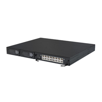
3.1 ECC800-Pro 3.1.1 Product Configuration The ECC800-Pro data center controller is used to monitor the devices and environment in the smart module. It consists of the power module and main control module. You can insert and remove the power module. - Page 25 (1) 53.5V DC_OUT1 (2) 53.5V DC_OUT2 (3) AC_INPUT1 (4) AC_INPUT2 Power Port The ECC800-Pro provides four power ports, including two AC input ports (AC_INPUT1 and AC_INPUT2) and two DC output ports (DC_OUTPUT1 and DC_OUTPUT2). Table 3-3 provides the power port pin definitions.
-
Page 26: Main Control Module
(13) AIDI_3 (14) DO/12V (15) RF_Z (16) WLAN (17) 4G (18) SW button Figure 3-4 ECC800-Pro main control module (side view) (1) SIM card slot (2) Micro SD card slot (reserved) Issue 02 (2020-09-07) Copyright © Huawei Technologies Co., Ltd. - Page 27 ECC800 Data Center Controller User Manual (for ECC800-Pro) 3 Device Description Specifications Table 3-4 Technical specifications of the ECC800-Pro main control module Item Specifications Power input ● Supports one AC input or two AC inputs ● Rated voltage: 200–240 V AC ●...
- Page 28 ● Supports USB 2.0 and 5 V, 1 A power supply. ● After installing the WiFi module, connect the WiFi module to the ECC800-Pro using the app on the mobile phone or tablet computer to view the basic information about the smart module, such as layout, resources, energy efficiency, environment, and alarms.
- Page 29 DC-HSPA+/HSPA+/HSPA/UMTS: 850/900/1900/2100 GSM/GPRS/EDGE: 850/900/1800/1900 MHz 3G/4G EIRP (max.) 23 dBm Communications Port The ECC800-Pro provides the following communications ports. Figure 3-5 shows the pins of the RJ45 port. Figure 3-5 RJ45 port pins There are four GE ports, that is, two WAN ports (WAN1 and WAN2) and two LAN ports (LAN1/POE and LAN2/POE).
- Page 30 ● Steady on: The 12 V DC output is normal. ● Off: No 12 V DC output is provided. Table 3-9 COM3/12V port pin definitions Item Description Pin1 RS485+ sequence Pin2 RS485- Pin3 12V DC_OUT Pin4 RS485+ Issue 02 (2020-09-07) Copyright © Huawei Technologies Co., Ltd.
- Page 31 6 and Pin 7 can detect the output status of passive dry contact type sensors. Pin 3 and Pin 7 can detect temperature sensors. Table 3-11 AIDI_1, AIDI_2 and AIDI_3 ports pin definitions Item Description Pin1 Type_1 sequence Pin2 Type_2 Pin3 12V DC Issue 02 (2020-09-07) Copyright © Huawei Technologies Co., Ltd.
- Page 32 ● Steady on: The 12 V DC output is normal. ● Off: No 12 V DC output is provided. Table 3-13 USB port pin definitions Item Description Pin sequence Pin1 Pin2 Pin3 Pin4 Issue 02 (2020-09-07) Copyright © Huawei Technologies Co., Ltd.
- Page 33 ECC800 Data Center Controller User Manual (for ECC800-Pro) 3 Device Description Indicators Table 3-14 Indicators on the ECC800-Pro main control module Indicator Color Name Status Description Green Running status Steady on The power supply is normal, indicator the program is being loaded.
-
Page 34: Power Module
1s and then off for 1s). Blinking at The converter application short program is being loaded (the intervals indicator blinks at 4 Hz, on for 0.125s and then off for 0.125s). Issue 02 (2020-09-07) Copyright © Huawei Technologies Co., Ltd. -
Page 35: Southbound Device Introduction
1s). Fault Steady on The converter locks out due to indicato output overvoltage. The converter delivers no output due to internal faults. The converter is working properly. 3.2 Southbound Device Introduction Issue 02 (2020-09-07) Copyright © Huawei Technologies Co., Ltd. -
Page 36: Uim20A Expansion Module
Table 3-17 UIM20A expansion module specifications Item Specifications Width 120 mm Depth 200 mm Height 43 mm Operating –30°C to +65°C temperature Installation Installed in a 19-inch rack requirement Environmen RoHS5 protection Issue 02 (2020-09-07) Copyright © Huawei Technologies Co., Ltd. - Page 37 ● The 12 V DC power supply can be switched on or off and is on by default. Connects to the ECC800-Pro through the PoE port. DIP switch ● One 4-bit DIP switch is used to set the RS485 address.
- Page 38 (blinking at long intervals (0.5 intervals Hz), on for 1s and then off for 1s). Blinking The communication is interrupted or the ECC800-Pro is at short unsuccessfully registered (blinking at 2.5 Hz, on for 0.2s intervals and then off for 0.2s).
-
Page 39: Rack Environment Unit
(5) COM2/12V port (6) COM3 port (7) COM4 port (8) NTC1–3 (9) NTC4–6 (10) AI/DI_1 port (11) AI/DI_2 port (12) 12V_1 port (13) 12V_2 port (14) BLINK button (15) Status indicator Issue 02 (2020-09-07) Copyright © Huawei Technologies Co., Ltd. - Page 40 0.5 Hz, on for 1s and then off for 1s). Blinking at PoE communication fails (the short indicator blinks at 4 Hz, on for intervals 0.125s and then off for 0.125s). Issue 02 (2020-09-07) Copyright © Huawei Technologies Co., Ltd.
-
Page 41: Smart Eth Gateway
No system alarm is generated. 3.2.3 Smart ETH Gateway A smart ETH gateway allows the extension of the 53.5 V DC power supply and FE communication for the ECC800-Pro and can be flexibly deployed in a smart module. Figure 3-9 Smart ETH gateway... - Page 42 The smart ETH gateway indicator long successfully registers with intervals the ECC800-Pro and the software runs properly (the indicator blinks at 0.5 Hz, on for 1s and then off for 1s). Issue 02 (2020-09-07) Copyright © Huawei Technologies Co., Ltd.
-
Page 43: Access Control System
Item Specifications Chip model Chip name Mifare 1K (S50) card Chip type Philips Mifare 1 IC S50 Operating frequency 13.56 MHz Read/write distance 1–3 cm Storage capacity 8 kbit, 16 partitions Issue 02 (2020-09-07) Copyright © Huawei Technologies Co., Ltd. -
Page 44: Access Actuator
3.2.4.1.1 Access Actuator The access actuator is the control component for the aisle door in a smart module. It connects to the ECC800-Pro controller over FE port, wireless networking (802.15.4). It opens the magnetic lock by detecting the card swiping information of the card reader, door open button information, and fire linkage information. - Page 45 Supported Indicators Table 3-29 Access actuator indicators Indicator Color Name Status Green Power input ● Steady on: The power input is normal. status ● Off: There is no power input. indicator Issue 02 (2020-09-07) Copyright © Huawei Technologies Co., Ltd.
- Page 46 1s and then off for 1s). ● Blinking at short intervals: The communication fails or the access actuator fails to register with the ECC800-Pro (the indicator blinks at 4 Hz, on for 0.125s and then off for 0.125s). ● Blinking: The indicator blinks at super short intervals for 0.5s (blinking at 10...
-
Page 47: Fingerprint And Card Reader With A Keypad
Rated operating current 300 mA±15% Card type supported IC card Authorized storage A maximum of 3000 authorized users, with a maximum of 6000 fingerprints Communications mode RS485 and Wiegand communications ports Issue 02 (2020-09-07) Copyright © Huawei Technologies Co., Ltd. -
Page 48: Fingerprint And Card Reader
The indicator blinks blue, red, and blue in order. Buzzer sounds The buzzer sounds once. 3.2.4.1.3 Fingerprint and Card Reader Figure 3-12 Fingerprint and card reader (1) Fingerprint reader (2) LED indicator Issue 02 (2020-09-07) Copyright © Huawei Technologies Co., Ltd. - Page 49 Fingerprint reader The indicator turns on (white). Buzzer sounds The buzzer sounds once. Card swiping LED indicator The indicator blinks blue, red, and blue in order. Buzzer sounds The buzzer sounds once. Issue 02 (2020-09-07) Copyright © Huawei Technologies Co., Ltd.
-
Page 50: Card Reader With A Keypad
Static standby current: 80 mA; dynamic operating current (card swiping, key pressing): 150 mA; minimum input current: 12 V DC/300 mA Communication mode Wiegand communications port 3.2.4.1.5 Magnetic Lock Figure 3-14 Double-door magnetic lock Issue 02 (2020-09-07) Copyright © Huawei Technologies Co., Ltd. -
Page 51: Cabinet Access Control System
The system displays the status of cabinet doors and locks in real time, the system displays the status of cabinet doors and locks in real time and reports the unauthorized door opening. ● The system supports remote unlocking. Issue 02 (2020-09-07) Copyright © Huawei Technologies Co., Ltd. - Page 52 The cabinet door can be opened with only the password and without the key. ● The user can set a password. ● A password should contain at least three digits. ● The password can be reset if the user forgot it. Issue 02 (2020-09-07) Copyright © Huawei Technologies Co., Ltd.
-
Page 53: Cabinet Electronic Clasp Lock
The cabinet electronic clasp lock is used to manage access control. It can be automatically unlocked, or manually locked and unlocked. Figure 3-19 Cabinet electronic clasp lock (1) LED indicator (2) DIP switch (3) RJ45 power port Issue 02 (2020-09-07) Copyright © Huawei Technologies Co., Ltd. - Page 54 (blinking at 10 Hz, on for short 0.05s and then off for interv 0.05s). The cycle lasts for Alarm Stead A system failure alarm is indicator y on generated. Issue 02 (2020-09-07) Copyright © Huawei Technologies Co., Ltd.
-
Page 55: Smart Module Actuator
(COM1/COM2) (5) DIP switch (6) AC OUT power (7) Terminal cover (8) AC IN power input output ports port (9) Fuse (10) DO/DI ports (11) DO/12V port (12) AI/DI ports Issue 02 (2020-09-07) Copyright © Huawei Technologies Co., Ltd. - Page 56 ● Press the button for less than 1 second to start blinking. ● Hold down the button for 1–5 seconds to search for a network and start networking. ● Hold down the button for more than 6 seconds to clear network parameters. Issue 02 (2020-09-07) Copyright © Huawei Technologies Co., Ltd.
- Page 57 0.05s and then off for 0.05s) and then turns off for 0.5s. The cycle lasts for 5s. Alarm Steady on A system failure alarm is indicator generated. No system alarm is generated. Issue 02 (2020-09-07) Copyright © Huawei Technologies Co., Ltd.
-
Page 58: Ac Actuator
(disabled by default), or signals from the light button. It also provides a charging port for the PAD (AC OUT2). Issue 02 (2020-09-07) Copyright © Huawei Technologies Co., Ltd. - Page 59 Charging stops when the PAD battery level reaches 100%. charging When the battery level is lower than 40% (default value, which can be set to 30, 40, or 50), charging starts. Issue 02 (2020-09-07) Copyright © Huawei Technologies Co., Ltd.
- Page 60 A system failure alarm is indicator generated. No system alarm is generated. RF_Z Green Communic Steady on No network parameters exist, ation or a network is to be created. status indicator Issue 02 (2020-09-07) Copyright © Huawei Technologies Co., Ltd.
-
Page 61: Skylight Actuator
(5) BLINK button (6) Status indicator (7) Address DIP (8) COM1 port switch (9) COM2 port (10) PoE port (11) 48 V power port Issue 02 (2020-09-07) Copyright © Huawei Technologies Co., Ltd. - Page 62 Green Power input Steady on The power input is normal. status There is no power input. indicator Green Running The power is abnormal or status the board program is indicator loading. Issue 02 (2020-09-07) Copyright © Huawei Technologies Co., Ltd.
- Page 63 0.5s and intervals then turns off for 0.5s). Communications Ports The skylight actuator provides one DO port (LOCK/GND) and one DI port (BUTTON/GND). Table 3-45 lists the LOCK/GND/BUTTON/GND port pin definitions. Issue 02 (2020-09-07) Copyright © Huawei Technologies Co., Ltd.
-
Page 64: Multi-Functional Sensor
A multi-functional sensor integrates the temperature and humidity (T/H) sensor, smoke sensor and infrared detection. The multi-functional sensor can connect to the ECC800-Pro over FE or wireless communication. NO TE The infrared detection function is enabled only when the intelligent lighting function is enabled. - Page 65 The multi-functional sensor running long successfully registers with status intervals the ECC800-Pro and the indicator software runs properly (the indicator blinks at 0.5 Hz, on for 1s and then off for 1s). Issue 02 (2020-09-07) Copyright © Huawei Technologies Co., Ltd.
-
Page 66: Smoke Sensor
(the indicator blinks at super short short intervals for 0.5s and intervals then turns off for 0.5s). 3.2.9 Smoke Sensor Smoke sensors are used to detect the smoke concentration. Issue 02 (2020-09-07) Copyright © Huawei Technologies Co., Ltd. -
Page 67: Temperature Sensor
Diameter: 112 mm, height: 41 mm 3.2.10 Temperature Sensor The temperature sensor (BOM number: 33010348) is used for the surface temperature measure, industrial process control, measurement instrument, etc. Figure 3-25 Temperature sensor Issue 02 (2020-09-07) Copyright © Huawei Technologies Co., Ltd. -
Page 68: Cabinet Temperature Sensor
● ±2°C (≥ –20°C, < –10°C) & (> +55°C, ≤ +70°C) ● ±0.5°C (25°C) Operating temperature –20°C to +70°C Operating humidity 5%–95% RH Storage temperature –40°C to +70°C Storage humidity ≤ 95% RH, non-condensing Issue 02 (2020-09-07) Copyright © Huawei Technologies Co., Ltd. -
Page 69: Alarm Beacon
The smart U space manager is designed for IT asset management of the data center. The system automatically detects the physical location of IT devices in the data center, collects IT asset codes and the information about U space usage. Issue 02 (2020-09-07) Copyright © Huawei Technologies Co., Ltd. -
Page 70: Elight Actuator
≤ 0.2 kg (main control box), ≤ 0.35 kg (asset detection strip) Installation mode Magnet-based installation 3.2.14 eLight Actuator The eLight actuator has the function of associating alarms, access authorization status, and atmospheres. Issue 02 (2020-09-07) Copyright © Huawei Technologies Co., Ltd. - Page 71 Associated alarm severity is set to None. Other color light Steady on or The device is abnormal or cables are blinking incorrectly connected to terminals R, G, and B. Figure 3-29 eLight actuator Issue 02 (2020-09-07) Copyright © Huawei Technologies Co., Ltd.
-
Page 72: Water Sensor
3.2.15.1 WLDS600 Water Sensor The WLDS600 water sensor consists of a water detection cable, a water detector with the BOM number of 33010556, an extension line, and a conversion cable. Issue 02 (2020-09-07) Copyright © Huawei Technologies Co., Ltd. - Page 73 W x H) Power supply 9–16 V DC or 9–16 V AC Impulse ≤ 450 mA current Power < 2 W dissipation Power, RJ45 female connector 1 piece communicatio n connector Issue 02 (2020-09-07) Copyright © Huawei Technologies Co., Ltd.
-
Page 74: Wlds900 Water Sensor
DIN track install supported. mode 3.2.15.2 WLDS900 Water Sensor The WLDS900 water sensor with the BOM number of 33010352 consists of a water detection cable, a water detector, and a conversion cable. Issue 02 (2020-09-07) Copyright © Huawei Technologies Co., Ltd. -
Page 75: Electrode Water Sensor
–20°C to +70°C temperature Storage –40°C to +85°C temperature Humidity 10%–80% RH (non-condensing) 3.2.15.3 Electrode Water Sensor The electrode water sensor with the BOM number of 33010444 contains electrode probes and cables. Issue 02 (2020-09-07) Copyright © Huawei Technologies Co., Ltd. -
Page 76: Wifi Module
The WiFi module provides WiFi signals for equipment such as pads and mobile phones to interact with the host computer. Figure 3-33 WiFi module Table 3-59 Technical specifications Item Specifications Wireless IEEE 802.11n, IEEE 802.11g, and IEEE 802.11b standard Issue 02 (2020-09-07) Copyright © Huawei Technologies Co., Ltd. -
Page 77: Eth Converter
Power < 0.8 W 3.2.17 ETH Converter The ETH converter is used to convert the Modbus–RTU protocol or CAN protocol to the Modbus-MAC protocol for connecting to the PoE bus. Issue 02 (2020-09-07) Copyright © Huawei Technologies Co., Ltd. - Page 78 If you press the BLINK button, the RUN indicator blinks button intermittently at super short intervals (blinking at super short intervals for 0.5s and then off for 0.5s) for 10 seconds. E-label Supported Issue 02 (2020-09-07) Copyright © Huawei Technologies Co., Ltd.
-
Page 79: Pad
The pad allows the wireless access from the data center management system. You can monitor the equipment in the data center and environmental parameters in real time over the app. The recommended model is T5-10. Issue 02 (2020-09-07) Copyright © Huawei Technologies Co., Ltd. - Page 80 ● LPDDR3 extension card: Micro SD, a maximum of 256 GB (non-standard configuration) Button/Port ● Touch button + power switch and volume button ● 3.5 mm stereo headphones port ● Micro SD card port ● MicroUSB port Issue 02 (2020-09-07) Copyright © Huawei Technologies Co., Ltd.
-
Page 81: T/H Sensor
● Power adapter charge time: about 3.5 hours (5 V 2 A adapter) 3.2.19 T/H Sensor 3.2.19.1 T/H Sensor (BOM Number: 33010346) Figure 3-36 Appearance The T/H sensor uses an RJ45 connector. Issue 02 (2020-09-07) Copyright © Huawei Technologies Co., Ltd. - Page 82 Temperature accuracy ≤ ±0.3°C (25°C) Humidity measuring range 0%–100% RH Humidity accuracy ≤ ±4% RH (25°C, 30%–80% RH) Operating voltage 9–16 V DC Storage temperature –40°C to +80°C (non-condensing) Output RS485 Issue 02 (2020-09-07) Copyright © Huawei Technologies Co., Ltd.
-
Page 83: T/H Sensor (Bom Number: 02310Nbs)
RS485+ Pin5 or Pin 6 Table 3-67 T/H sensor specifications Item Specifications Temperature measuring range –20°C to +70°C Temperature accuracy ±1°C Operating temperature –10°C to +55°C Operating voltage 9–16 V DC Issue 02 (2020-09-07) Copyright © Huawei Technologies Co., Ltd. -
Page 84: T/H Sensor (Bom Number: 33010516)
The appearance of the T/H sensor depends on the onsite delivery. Figure 3-41 Pins of an RJ45 connector Table 3-68 RJ45 port pin definitions Description Pin1 or Pin 4 Pin2 or Pin 5 Pin3 Pin6 Pin7 Reserved Issue 02 (2020-09-07) Copyright © Huawei Technologies Co., Ltd. -
Page 85: T/H Sensor (Bom Number: 02311Fqg)
≤±1°C (–20°C to ≤±5% RH (25°C, 20%–80% +60°C) Extended temperature Provides two RJ45 ports to connect to six NTC collection port temperature sensors, each RJ45 port connecting to three NTC temperature sensors. Issue 02 (2020-09-07) Copyright © Huawei Technologies Co., Ltd. -
Page 86: T/H Sensor (Bom Number: 02312Pbl)
Provides two RJ45 ports to connect to six NTC temperature temperature sensors, each RJ45 port connecting to three NTC collection port temperature sensors. Signal port RS485 Power supply 5–16 V DC (typical value 12 V DC) Issue 02 (2020-09-07) Copyright © Huawei Technologies Co., Ltd. -
Page 87: Infrared Remote Control Module
The baud rate can be 9600 bit/s. Infrared emission ≤ 10 m distance Power supply 9–16 V DC Power ≤ 350 mA Operating temperature –10°C to +50°C Operating humidity 5%–95% RH Issue 02 (2020-09-07) Copyright © Huawei Technologies Co., Ltd. -
Page 88: Intelligent Battery Monitoring System
(Optional) When a battery system needs to be managed by multiple iBOXs, the iBOXs can be connected to northbound devices using straight-through cables (the ECC800-Pro supports four iBOXs in parallel through the smart ETH gateway) without cascading. Issue 02 (2020-09-07) -
Page 89: Ibox
It collects battery status data from the downstream iBAT groups through wireless communication, and sends the data to the ECC, UPS, and the third-party network management system (NMS) through COM or PoE ports. Issue 02 (2020-09-07) Copyright © Huawei Technologies Co., Ltd. - Page 90 (14) RF_Z indicator (15) Delivered antenna Figure 3-47 iBOX bottom view (1) Fastener (2) Micro SD card slot (3) Default button (IP reset) (4) ADDR dual in-line package (DIP) switch (RS485 communications address) Issue 02 (2020-09-07) Copyright © Huawei Technologies Co., Ltd.
- Page 91 Table 3-74 –48 V, 0.5 A port pin definitions Definition Description The system provides 48 V DC operating voltage – in this scenario. PoE Port Figure 3-49 PoE port pins Issue 02 (2020-09-07) Copyright © Huawei Technologies Co., Ltd.
- Page 92 4, 5 P45_P1 RX– 7, 8 P78_P1 COM Port Figure 3-50 COM port pins Table 3-76 COM port pin definitions Signal Description RS485+ Two cascaded RS485 communication ports RS485– RS485+ RS485– Issue 02 (2020-09-07) Copyright © Huawei Technologies Co., Ltd.
- Page 93 Figure 3-51 HALL current monitoring port pins Table 3-78 Pin definitions for HALL current monitoring ports Definition Description +12V Detect the charge and discharge currents of –12V four battery strings or eight battery routes. Issue 02 (2020-09-07) Copyright © Huawei Technologies Co., Ltd.
- Page 94 Monitors ● Grounded: The Disconnect routes. the battery battery circuit circuit breaker is ON. breaker ● Disconnected: The battery circuit breaker is OFF. Issue 02 (2020-09-07) Copyright © Huawei Technologies Co., Ltd.
- Page 95 BCBs are circuit circuit connected breaker is breaker to the input. status ● Disconnect ed: The battery circuit breaker is OFF. Issue 02 (2020-09-07) Copyright © Huawei Technologies Co., Ltd.
- Page 96 Indicators Table 3-82 Indicators Indicat Color Meaning Status Description Measure RF_Z Green Wireless Steady on No network Requires no communi parameters handling. cation exist. (A status network is to be created.) Issue 02 (2020-09-07) Copyright © Huawei Technologies Co., Ltd.
- Page 97 3 minutes.) ● If no, go to the next step. 2. Check whether the device is malfunctioning. ● If yes, replace the device. ● If no, contact Huawei technical support. Issue 02 (2020-09-07) Copyright © Huawei Technologies Co., Ltd.
- Page 98 Creates a network if no network button for more has been created. Switches than 1s but less between network organization and than 5s. data transmission if a network has been created. Issue 02 (2020-09-07) Copyright © Huawei Technologies Co., Ltd.
-
Page 99: Ibat
● Supports the hibernation function. (When it detects that the battery voltage is low, it will enter the low-power mode.) ● Communicates with the iBOX wirelessly. iBAT Appearance Figure 3-53 iBAT2.0 Issue 02 (2020-09-07) Copyright © Huawei Technologies Co., Ltd. - Page 100 (The iBAT is waiting to connect to a network.) Blinking at ● Network parameters are super short being cleared. intervals ● The iBAT is blinking. (iBattery 2.0) Blinking at short intervals (iBattery 3.0) Issue 02 (2020-09-07) Copyright © Huawei Technologies Co., Ltd.
- Page 101 Initializes the network parameters if there is a network. Button Hold down the Clears the current network and resets holding down button for more the wireless module; disconnects the than 5s. network. Issue 02 (2020-09-07) Copyright © Huawei Technologies Co., Ltd.
-
Page 102: Ui Description
ECC800 Data Center Controller User Manual (for ECC800-Pro) 4 UI Description UI Description 4.1 WebUI For data transmission security, the ECC800-Pro supports WebUI access through TLS. Figure 4-1 Home page Issue 02 (2020-09-07) Copyright © Huawei Technologies Co., Ltd. - Page 103 ● IP device num is 100 Group. example, set by default. smart cooling ● Online detection product timeout interval is parameters, delete 30 by default. devices failing in communication, and set AIDI device parameters. Issue 02 (2020-09-07) Copyright © Huawei Technologies Co., Ltd.
- Page 104 Query device – nce Data performance data. Operation – Query operation – logs. Access – Query access – Event control events. Export – Export historical – Data data and device data. Issue 02 (2020-09-07) Copyright © Huawei Technologies Co., Ltd.
- Page 105 Managem delete videos. NetEco Set SNMP and Server IP is Applicatio NetEco 192.168.8.11 by default. communications Port number is 31220 parameters. by default. The Network port for link establishment is WAN_1. Issue 02 (2020-09-07) Copyright © Huawei Technologies Co., Ltd.
- Page 106 Alarm Basic Alarm Set basic alarm – Parameter Parameters parameters and alarm association Alarm – parameters. Linkage Performa Performance Enable or disable – Parameters the device Parameter performance statistics function. Issue 02 (2020-09-07) Copyright © Huawei Technologies Co., Ltd.
- Page 107 Configura – Import and export – tion File configuration files to configure devices quickly, and restore factory defaults. Fault – Export fault – Informati information. Issue 02 (2020-09-07) Copyright © Huawei Technologies Co., Ltd.
- Page 108 ● c: Multi-Module Monitoring is displayed on the Home page only after you set Smart Module Cascading. ● d: If the system type is FusionModule2000 or FusionModule5000, this function is unavailable. ● e: This function is available only in some customized projects. Issue 02 (2020-09-07) Copyright © Huawei Technologies Co., Ltd.
-
Page 109: Mobile Phone App
Allows you to view details about devices under the monitoring system, power distribution, aisle, cooling, and cabinet types. Software Allows you to upgrade the software using a USB flash drive Upgrade or locally. Paramet er Sync Issue 02 (2020-09-07) Copyright © Huawei Technologies Co., Ltd. -
Page 110: Pad App
Allows you to view device asset details such as electronic Details labels of system devices and other devices. Device Check the Software Version and Hardware Version of the Version device. Info 4.3 Pad App Figure 4-3 Home screen Issue 02 (2020-09-07) Copyright © Huawei Technologies Co., Ltd. - Page 111 Allows you to view device asset details such as electronic Details labels of system devices and other devices. Device Check the Software Version and Hardware Version of the Version device. Info Issue 02 (2020-09-07) Copyright © Huawei Technologies Co., Ltd.
-
Page 112: Power-On Commissioning
You have obtained the ECC800-Pro IP address as well as the user name and password used for WebUI login. ● A PC with an IP address in the same network segment as the ECC800-Pro IP address is prepared, and the PC has connected to the WAN1 port on the ECC800-Pro. - Page 113 ● If the ECC800-Pro connects to a LAN and a proxy server has been selected, perform Step Step 3.4. ● If the ECC800-Pro connects to the Internet, and the PC in a LAN accesses the Internet over a proxy server, do not perform Step 3.3 Step 3.4.
- Page 114 Figure 5-2 Setting parameters NO TE When switching between different versions of the ECC800-Pro on your PC, you are advised to clear the historical Internet Explorer cache. Failing to do so may cause some information missed or exception after login. The following provides the details: 1.
-
Page 115: Performing Startup Password Authentication (For Fusionmodule800)
– An account is logged out due to timeout if no operation is performed within 10 minutes after system login. – A maximum of three users can log in to the ECC800-Pro WebUI at the same time. ----End 5.2 Performing Startup Password Authentication (for... - Page 116 Hold down the SW button on the ECC800-Pro for less than 3s to enable the WiFi function. Issue 02 (2020-09-07) Copyright © Huawei Technologies Co., Ltd.
-
Page 117: Commissioning Configuration Wizard
– You are advised to use a mobile phone that has not been rooted to reduce the risk of information leakage. – It is recommended that you use different user names to log in to both the ECC800-Pro WebUI and app at the same time. If you use the same user name to log in to the WebUI and app at the same time, either of them will be forcibly logged out. -
Page 118: Configuring Event Notification
Step 1 Log in to the ECC800-Pro WebUI as an administrator. NO TE The configuration wizard is displayed when you log in to the ECC800-Pro WebUI for the first time or the system type is switched. Step 2 Choose Maintenance > Configuration Wizard to access the parameter configuring page for the deployment wizard. - Page 119 User Manual (for ECC800-Pro) 5 Power-On Commissioning NO TE 1. The ECC800-Pro supports only SMS notification service but not data service by using the 4G module. 2. China: 2G and 4G networks support China Unicom or China Mobile SIM cards, and 3G networks support only China Unicom SIM cards.
- Page 120 163 Mail, 139 Mail smtp. press Enter Non- 126 Mail, 139.com to obtain encryption: 25 and QQ email server Hotmail smtp- TLS encryption: Mail. IP addresses. mail.outloo k.com Issue 02 (2020-09-07) Copyright © Huawei Technologies Co., Ltd.
- Page 121 NO TE The email address is used only for configuring the email function and is not used for other purposes. The address is encrypted during transmission in the ECC800-Pro to ensure that the personal data of users is fully protected.
- Page 122 The mobile phone number is used only for configuring the SMS function and is not used for other purposes. The phone number is encrypted during transmission in the ECC800-Pro to ensure that the personal data of users is fully protected.
- Page 123 Mailbox Settings. Mobile Phone Number can be selected after it is added in SMS Settings. Step 6 Click Confirm to access the re-authentication page. Enter Login password and click Submit. ----End Issue 02 (2020-09-07) Copyright © Huawei Technologies Co., Ltd.
-
Page 124: Commissioning The New Main Way
Then, you need to set parameters for the general input units and power distribution units; otherwise, a false alarm may be generated. Procedure Step 1 Set parameters for general input units on the ECC800-Pro WebUI. Set parameters for general input unit 1. Table 5-3 Power distribution settings for a general input unit... - Page 125 Path: Maintenance > Parameter Sync Step 2 Set parameters for power distribution units on the ECC800-Pro WebUI. (Optional) To modify the branch signal name of the power distribution unit, choose System Settings > Signal Name Modify and access the Batch Signal Configuration to modify the name, and then tap Submit.
-
Page 126: Commissioning The Elight
Toggle switches 1 to 4 of the DIP switch specify the device address in binary mode. ON indicates 1, and OFF indicates 0. Table 5-5 Setting a device address Address Toggle Toggle Toggle Toggle Switch 1 Switch 2 Switch 3 Switch 4 Issue 02 (2020-09-07) Copyright © Huawei Technologies Co., Ltd. - Page 127 Test. Step 3 Set eLight parameters. Log in to the ECC800-Pro WebUI as an administrator. In the Smart Module View, click Modify Device. Select an eLight actuator under Devices, drag it to the access actuator to which you want to bind the eLight actuator, and click Exit Edit Mode.
- Page 128 NOTE ● Critical: red light ● Major: orange light ● Minor: yellow light ● Warning: white light Issue 02 (2020-09-07) Copyright © Huawei Technologies Co., Ltd.
-
Page 129: Commissioning The Elight (For Fusionmodule800)
Toggle Toggle Toggle Switch 1 Switch 2 Switch 3 Switch 4 Step 2 Add an eLight. Log in to the ECC800-Pro WebUI as an administrator. Add an eLight. Table 5-10 Adding an eLight Path Parameter Setting Choose System Device Select eLight Actuator from the Settings >... - Page 130 Step 3 Set eLight parameters. Log in to the ECC800-Pro WebUI as an administrator. Choose Monitoring > Aisle > eLight Actuator Group > eLight Actuator. The Running Parameters page is displayed.
-
Page 131: Commissioning The Pdu2000 (For Fusionmodule800)
Clever PDU2000-M(C) Haipengxin PDU2000-M(H) a: The barcode starts with 21 and is attached to the device. Procedure Step 1 Set the PDU2000 monitoring parameters. ● Set the PDU2000-M (C) monitoring parameters. Issue 02 (2020-09-07) Copyright © Huawei Technologies Co., Ltd. - Page 132 The display of a single-phase module is used as an example. – After the PDU2000-M (H) is powered on, press MENU. The LCM displays – Press MENU again to access the device communications address screen. Issue 02 (2020-09-07) Copyright © Huawei Technologies Co., Ltd.
- Page 133 Press MENU to confirm the settings. NO TE If modification is successful, is displayed: If modification fails, is displayed: Step 2 Add a PDU2000. Log in to the ECC800-Pro WebUI as an administrator. Add a PDU2000. Table 5-13 Adding a PDU2000 Path Parameter Setting...
-
Page 134: Commissioning Cabinet Electronic Clasp Lock (For Fusionmodule800)
COM2 port on the ECC800-Pro; one end of another network cable is connected to the RS485_IN port on the first cabinet electronic clasp lock of an even-numbered cabinet, and the other end of the cable is connected to the COM3 port on the ECC800-Pro. - Page 135 Switch 5 Switch 6 Step 4 Add the cabinet electronic clasp locks. Log in to the ECC800-Pro WebUI as an administrator. Create a cabinet view in Smart Module View on the home page. Add a cabinet electronic clasp lock. Table 5-15 Adding an E-LOCK...
- Page 136 5 Power-On Commissioning – If the connection fails, check whether the device is properly connected to the ECC800-Pro, whether the device and ECC800-Pro are running properly, and whether the parameter settings are consistent with the device parameters. Connect the electronic locks of other cabinets.
-
Page 137: Feature Description
Step 3 Set device performance parameters, select the performance parameters to be submitted in the first column, set Collecting Data, and click Submit. After the parameters are successfully submitted, is displayed in the setting result of the Issue 02 (2020-09-07) Copyright © Huawei Technologies Co., Ltd. -
Page 138: Setting Ecc800-Pro Cascading
Context A maximum of three ECC800-Pros can be cascaded. After the IP addresses of other smart module ECC800-Pros in the room are added to an ECC800-Pro, their active alarms and PUE data can be displayed and viewed. You can click links on the cascading management page of the master ECC800-Pro to display the login pages of the other ECC800-Pros. -
Page 139: Commissioning A Uim20A Expansion Module
Procedure Step 1 Log in to the ECC800-Pro WebUI as an administrator. Step 2 Choose System Settings > Device Management, and click Auto Discover Device to add the device. Devices connected to the UIM can be identified. - Page 140 Table 6-2 Cable connection mode in the UIM one-to-four scenario COM Port COM1 COM3 COM5 COM7 Connected Cabinet 1 Cabinet 2 Cabinet 3 Cabinet 4 Cabinet COM Port COM2 COM4 COM6 COM8 Issue 02 (2020-09-07) Copyright © Huawei Technologies Co., Ltd.
- Page 141 UIM blinks fast, and the dialog box for binding IT cabinets and devices shows the UIM that is blinking. NO TE You can determine the IT cabinet that houses the UIM through indicator blinking. Then, you can change the IT cabinet name. Issue 02 (2020-09-07) Copyright © Huawei Technologies Co., Ltd.
-
Page 142: Access Management
Step 9 (Optional) Click to delete a device binding relationship. Step 10 Choose Home > Plan View on the ECC800-Pro WebUI, and drag the dry contact device to the corresponding position in the Smart Module View pane based on the actual device layout. -
Page 143: Commissioning A Door Status Sensor (Connected To The Ai/Di Port On The Rack Environment Unit)
In this example, the door status sensor is connected to the AI/DI_1 port on the independent deployment AI_DI 1. Log in to the ECC800-Pro WebUI as an administrator. Choose System Settings > Signal Name Modify. The Batch Signal Configuration page is displayed. -
Page 144: Commissioning A Door Status Sensor (Connected To The Ai/Di Port On The Uim20A Expansion Module)
If multiple door status sensors are connected, commission one door status sensor first and then commission the other door status sensors in the same way. Procedure Step 1 Set parameters for a door status sensor. Issue 02 (2020-09-07) Copyright © Huawei Technologies Co., Ltd. -
Page 145: Commissioning The Door Status Sensor (Connected To The Ecc800-Pro)
In this example, the door status sensor is connected to the AI/DI_1 port on the user interface module1. Log in to the ECC800-Pro WebUI as an administrator. Choose System Settings > Signal Name Modify. The Batch Signal Configuration page is displayed. - Page 146 Step 2 If the number of cabinets is less than or equal to 2, set the door status sensor parameters. Log in to the ECC800-Pro WebUI as an administrator. Choose System Settings > Signal Name Modify. The Batch Signal Configuration page is displayed.
-
Page 147: Commissioning An Access Control Device And A Cabinet Electronic Lock
If an access control device and cabinet electric lock are installed, perform the following steps to configure it. Prerequisites When the fingerprint reader is connected to the ECC800-Pro for the first time, the permissions need to be synchronized. Procedure Step 1 Set the access user management and access permission management. - Page 148 Then, enter user ID*password#. To query the user ID, log in to the ECC800-Pro WebUI as an administrator. Choose System Settings > Access Management. In the Authorization area, view the user ID corresponding to the user name.
- Page 149 The fingerprint information is used only for configuring the access control function and is not used for other purposes. The fingerprint information is encrypted during transmission in the ECC800-Pro to ensure that the personal data of users is fully protected.
- Page 150 If the access control system uses a Card and password reader, choose Monitoring > Aisle > Access Actuator Group > Access Actuator n on the ECC800-Pro WebUI, click Running Parameters, and set Logical level configuration for reader removed of the corresponding card reader to High level alarm.
- Page 151 Choose Query > Access Event on the WebUI, you can view the type of this access control event. Issue 02 (2020-09-07) Copyright © Huawei Technologies Co., Ltd.
-
Page 152: Commissioning The Exit Button, Skylight Button, Atmosphere Light, Emergency Button, And Magnetic Lock
Follow-up Procedure Status Attempt to open the door The aisle door is You need to restore the by pressing the emergency opened successfully. emergency button. button when the aisle door is closed. Issue 02 (2020-09-07) Copyright © Huawei Technologies Co., Ltd. -
Page 153: Commissioning An Emergency Door Release Button
NO and COM on the emergency door release emergency door release button. button. ----End 6.5 Video Management 6.5.1 Preparing Documentation Before commissioning a camera, prepare the following documents in addition to this document. Issue 02 (2020-09-07) Copyright © Huawei Technologies Co., Ltd. -
Page 154: Networking Scenarios
Figure 6-8 Camera + VCN connecting to the ETH gateway NO TICE ● To ensure the normal operating of the ECC800-Pro, avoid high data traffic, such as the concurrent display of dynamic monitoring of cameras and VCN500 video playback. -
Page 155: Commissioning A Camera (Smart Eth Gateway Networking Scenario)
● Configure the camera or VCN internal IP address and the IP address of the LAN port on the ECC800-Pro in the same network segment. ● Configure the camera or VCN internal IP address and the IP address of the WAN_1 port on the ECC800-Pro in the same network. - Page 156 Step 1 Log in to the camera web system and enable ONVIF. Remove the network cables that connect the smart ETH gateway to the LAN1 and LAN2 ports on the ECC800-Pro. Use a network cable to connect the PC to the PoE port on the smart ETH gateway.
- Page 157 5. Set Automatic prompting for ActiveX controls to Enable, and set Download unsigned ActiveX controls and Initialize and script ActiveX controls not marked as safe for scripting to Prompt. 6. Click OK. Issue 02 (2020-09-07) Copyright © Huawei Technologies Co., Ltd.
- Page 158 Remove the network cable from the PC to the PoE port on the ETH gateway. Connect the PC to the LAN1 port on the ECC800-Pro using a network cable, and reconnect the network cable between the smart ETH gateway and the LAN2 port on the ECC800-Pro.
- Page 159 The IP address should be in the range of 192.168.248.50 to 192.168.248.199. Step 3 On the ECC800-Pro WebUI, click Add under Video Information. In the New Video Information dialog box that is displayed, enter camera or VCN information. ●...
- Page 160 Change IP camera ONVIF interface access password: If you have changed the default password for accessing the ONVIF interface of the IP camera, enter the new password in Password. Otherwise, the ECC800-Pro cannot collect motion detection alarms from the IP camera.
- Page 161 Choose Settings > Video/Audio/Image > Video Settings, and set camera stream type, primary stream, and secondary stream 1 parameters. NO TICE Set the encoding protocol to H.265. Figure 6-16 Setting primary stream parameters Issue 02 (2020-09-07) Copyright © Huawei Technologies Co., Ltd.
-
Page 162: Commissioning Ipc6325 Camera (Sd Card Configured)
If the VCN is not configured and an SD card is chosen, perform the following procedure. Procedure Step 1 Log in to the Huawei IPC WebUI. Step 2 Format the SD card. Choose Settings > System Configuration > Storage Management. - Page 163 Result Encoding Resolution Frame I-Frame Minimum Supported Protocol Rate Interval Bit Rate Video Required Storage Duration H.265 1080P H.264 1080P H.265 720P 0.8M H.264 720P H.265 720P 0.6M H.264 720P 0.8M Issue 02 (2020-09-07) Copyright © Huawei Technologies Co., Ltd.
- Page 164 Figure 6-19 Setting motion detection parameters Step 5 Set the deployment policy. Figure 6-20 Setting the deployment policy Step 6 Set the alarm linkage policy. Figure 6-21 Setting the alarm linkage policy ----End Issue 02 (2020-09-07) Copyright © Huawei Technologies Co., Ltd.
-
Page 165: Commissioning A C3220 Camera
● Configure the camera or VCN internal IP address and the IP address of the LAN port on the ECC800-Pro in the same network segment. ● Configure the camera or VCN external IP address and the IP address of the WAN_1 port on the ECC800-Pro in the same network. - Page 166 5. Set Automatic prompting for ActiveX controls to Enable, and set Download unsigned ActiveX controls and Initialize and script ActiveX controls not marked as safe for scripting to Prompt. 6. Click OK. Issue 02 (2020-09-07) Copyright © Huawei Technologies Co., Ltd.
- Page 167 4. Click Custom level. The Security Settings-Internet Zone dialog box is displayed. 5. Set Use Pop-up Blocker to Disable. 6. Click OK. Choose View > Network/Time > Second Protocol Parameters, and select Enable ONVIF. Issue 02 (2020-09-07) Copyright © Huawei Technologies Co., Ltd.
- Page 168 Remove the network cable from the PC to the PoE port on the ETH gateway. Connect the PC to the LAN1 port on the ECC800-Pro using a network cable, and reconnect the network cable between the smart ETH gateway and the LAN2 port on the ECC800-Pro.
- Page 169 The IP address should be in the range of 192.168.248.50 to 192.168.248.199. Step 3 On the ECC800-Pro WebUI, click Add under Video Information. In the New Video Information dialog box that is displayed, enter camera or VCN information. ●...
- Page 170 Adjust the lens if necessary. (Optional) Configure an SD card if the VCN is not configured. Choose Settings > Video/Audio/Image > Video Settings, and set camera stream type, primary stream, and secondary stream 1 parameters. Issue 02 (2020-09-07) Copyright © Huawei Technologies Co., Ltd.
- Page 171 ECC800 Data Center Controller User Manual (for ECC800-Pro) 6 Feature Description NO TICE Set the encoding protocol to H.265. Figure 6-28 Setting primary stream parameters Issue 02 (2020-09-07) Copyright © Huawei Technologies Co., Ltd.
-
Page 172: Commissioning A C3220 Camera (Sd Card Configured)
Choose Settings > System Configuration > Storage Management. The Storage Management page is displayed. Format the SD card. Step 3 Set the camera stream type and primary stream parameters. Path: Settings > Video/Audio/Image > Video Settings. Issue 02 (2020-09-07) Copyright © Huawei Technologies Co., Ltd. - Page 173 0.6 Mbit/s H.264 720P 0.8 Mbit/s Step 4 Choose Settings > Intelligent Analysis > Common Intelligence. Select Enable, click Add, add motion detection areas, set motion detection parameters, and click Save. Issue 02 (2020-09-07) Copyright © Huawei Technologies Co., Ltd.
-
Page 174: Commissioning A Camera (Lan Switch Networking Scenario)
Configure the PC IP address and the camera IP address in the same network segment. Enter the camera IP address (192.168.0.120 by default) in the address bar of the Internet Explorer and press Enter. Issue 02 (2020-09-07) Copyright © Huawei Technologies Co., Ltd. - Page 175 5. Set Automatic prompting for ActiveX controls to Enable, and set Download unsigned ActiveX controls and Initialize and script ActiveX controls not marked as safe for scripting to Prompt. 6. Click OK. Issue 02 (2020-09-07) Copyright © Huawei Technologies Co., Ltd.
- Page 176 Choose Settings > Video/Audio/Image > Video Settings, and set camera stream type, primary stream, and secondary stream 1 parameters. NO TICE Set the encoding protocol to H.265. Issue 02 (2020-09-07) Copyright © Huawei Technologies Co., Ltd.
- Page 177 ECC800 Data Center Controller User Manual (for ECC800-Pro) 6 Feature Description Figure 6-33 Setting primary stream parameters Issue 02 (2020-09-07) Copyright © Huawei Technologies Co., Ltd.
-
Page 178: Commissioning Ipc6325 Camera (Sd Card Configured)
If the VCN is not configured and an SD card is chosen, perform the following procedure. Procedure Step 1 Log in to the Huawei IPC WebUI. Configure the PC IP address and the camera IP address in the same network segment. Enter the camera IP address (192.168.0.120 by default) in the address bar of the Internet Explorer and press Enter. - Page 179 The Storage Management page is displayed. Format the SD card. Set the camera stream type and primary stream parameters. Path: Settings > Video/Audio/Image > Video Settings. Figure 6-36 Setting audio and video parameters Issue 02 (2020-09-07) Copyright © Huawei Technologies Co., Ltd.
- Page 180 Select Enable, click Add, add motion detection areas, set motion detection parameters, and click Save. Figure 6-37 Setting motion detection parameters Set the deployment policy. Figure 6-38 Setting the deployment policy Issue 02 (2020-09-07) Copyright © Huawei Technologies Co., Ltd.
-
Page 181: Commissioning A C3220 Camera
Enter the preset user name admin and the preset password HuaWei123, and click Log In. NO TE You need to set Internet Explorer before accessing the camera WebUI for the first time. Issue 02 (2020-09-07) Copyright © Huawei Technologies Co., Ltd. - Page 182 WebUI cannot be opened. 1. Choose Tools > Internet Options. The Internet Options dialog box is displayed. 2. Click the Advanced tab. 3. Select Use TLS 1.1 or Use TLS 1.2. 4. Click OK. Issue 02 (2020-09-07) Copyright © Huawei Technologies Co., Ltd.
- Page 183 Preview the site situation in real time and check the camera coverage through videos. Adjust the lens if necessary. On the View tab page, click the Network/Time tab to access the Network/ Time tab page. Figure 6-40 Setting the IP address Issue 02 (2020-09-07) Copyright © Huawei Technologies Co., Ltd.
- Page 184 Secondary DNS IP address. The default value is 0.0.0.0. On the View tab page, click the General tab to access the General tab page. Click Video. Figure 6-41 Setting primary stream parameters Issue 02 (2020-09-07) Copyright © Huawei Technologies Co., Ltd.
- Page 185 The encoding process of each slice is independent of each other. Therefore, the camera can encode and decode multiple slices in parallel, improving encoding and decoding performance. This parameter is selected by default. Issue 02 (2020-09-07) Copyright © Huawei Technologies Co., Ltd.
- Page 186 The bit rate range depends on the selected resolution. Bit rate value Average bit rate when Bit rate type is set to Constant bit rate. The bit rate range depends on the selected resolution. Issue 02 (2020-09-07) Copyright © Huawei Technologies Co., Ltd.
-
Page 187: Commissioning A C3220 Camera (Sd Card Configured)
Commission other cameras by referring to this section. 6.5.4.4 Commissioning a C3220 Camera (SD Card Configured) Context If the VCN is not configured and an SD card is chosen, perform the following procedure. Issue 02 (2020-09-07) Copyright © Huawei Technologies Co., Ltd. - Page 188 Choose Settings > System Configuration > Storage Management. The Storage Management page is displayed. Format the SD card. Set the camera stream type and primary stream parameters. Path: Settings > Video/Audio/Image > Video Settings. Issue 02 (2020-09-07) Copyright © Huawei Technologies Co., Ltd.
- Page 189 Bit Rate d Video Required Storage Duration H.265 1080P 1 Mbit/s H.264 1080P 1 Mbit/s H.265 720P 0.8 Mbit/s H.264 720P 1 Mbit/s H.265 720P 0.6 Mbit/s H.264 720P 0.8 Mbit/s Issue 02 (2020-09-07) Copyright © Huawei Technologies Co., Ltd.
-
Page 190: Initializing Vcn510 Disks
Step 1 Log in to the OMU portal of the VCN as user admin. Step 2 Choose Local Configuration > Local Disk. Step 3 In the upper-right corner of the RAID Groups area, click Initial disk. Issue 02 (2020-09-07) Copyright © Huawei Technologies Co., Ltd. - Page 191 Step 2 View the RAID group status in the RAID Groups area. If RAID1 is selected for the disks, RAID1 is created for both the system partition (used to store system data) and data partition (used to store recordings). Issue 02 (2020-09-07) Copyright © Huawei Technologies Co., Ltd.
- Page 192 For service security reasons, if users do not perform any operation for a long period of time, the OMU portal will return to the login page or does not stay at the Local Disk tab page. ----End Issue 02 (2020-09-07) Copyright © Huawei Technologies Co., Ltd.
-
Page 193: Setting Parameters On The Vcn Webui
– The following uses V100R003 as an example. Choose Local Configuration > Server configuration. Set the service IP address (internal IP address of the VCN), time zone, and time according to the site requirements. Issue 02 (2020-09-07) Copyright © Huawei Technologies Co., Ltd. - Page 194 NO TE Set NatIP to the external IP address of the VCN, which is the same as the external IP address mapped by the VCN on the ECC800-Pro. Set Module name to OMU and click Search. In the search result, click Edit in the row where the value of Parameter Name is OMUNatIP and set Value to the NATIP address of the MU.
- Page 195 OMU Portal system. ● (Optional) Set up a VCN stack. For details, log in to the https:// e.huawei.com/, search for the VCN product documentation, open the documentation, and see the section (Optional) Deploying IVS in Stack Mode.
-
Page 196: Setting Parameters On The Vcn Ivs Client
Method 2 1. Log in to the VCN OMU Portal, choose Local Configuration > Basic Configuration, and view Current version. 2. Log in to https://support.huawei.com/enterprise/, and search for Client Package.zip followed by the VCN model (Client Package.zip VCN540 for example). In the search result, click... - Page 197 Select the camera on the Cameras list and click Next. (Optional) Set recording parameters, and click Next. Set recording plan parameters in the Time settings. Drag the timeline to select the time segment for implementing video recording. Issue 02 (2020-09-07) Copyright © Huawei Technologies Co., Ltd.
-
Page 198: Linkage Control
Set other parameters based on the documentation delivered with the equipment or the documentation obtained by referring to the Preparing Documentation section, and click Finish. ----End 6.6 Linkage Control Issue 02 (2020-09-07) Copyright © Huawei Technologies Co., Ltd. -
Page 199: Fusionmodule2000 Linkage Control
6.6.1 FusionModule2000 Linkage Control Prerequisites ● You have obtained the IP address of the ECC800-Pro as well as the user name and password used for WebUI login. ● A PC with an IP address in the same network segment as that of the ECC800- Pro is prepared, and the PC has connected to port WAN1 on the ECC800-Pro. -
Page 200: Fire Control Linkage
A passive dry contact alarm signal of the customer's fire extinguishing system can be used to achieve the following purposes: (1) Open the skylight using the ECC800-Pro AI/DI port, so that the fire extinguishing system in the customer's equipment room can quickly function in the aisle. (2) Enable the aisle access control system and turn on the lighting to facilitate escape. - Page 201 6 Feature Description Figure 6-57 Installing cables between the fire controller and ECC800-Pro Step 2 Log in to the ECC800-Pro WebUI as an administrator. Step 3 Choose System Settings > Linkage Control. Step 4 Ensure that Enable linkage control function is Yes.
-
Page 202: High Temperature Linkage
The default status of high temperature linkage is off. Set it based on the actual situation. Procedure Step 1 Log in to the ECC800-Pro WebUI as an administrator. Step 2 Choose System Settings > Linkage Control. Step 3 Ensure that Enable linkage control function is Yes. -
Page 203: Optional) Commissioning An Intelligent Aisle Light
● The effective detection distance of the multi-functional sensor is 2.5 m. Procedure Step 1 Log in to the ECC800-Pro WebUI as an administrator. Issue 02 (2020-09-07) Copyright © Huawei Technologies Co., Ltd. - Page 204 That is, the RF_Z indicators on the ECC800-Pro and AC actuator are both steady green. ● If the RF_Z indicator on the ECC800-Pro is not steady green, hold down the SW button on the ECC800-Pro for 8 to 20 seconds to erase network parameters.
- Page 205 Select the actual camera type and go to the camera web page. For details, see the section about camera commissioning. Choose Settings > Network > Platform Connection > Second Protocol Parameters. On the ONVIF and GENETEC tab pages, set platform interconnection parameters. Issue 02 (2020-09-07) Copyright © Huawei Technologies Co., Ltd.
- Page 206 Select Enable, click Add, add motion detection areas, set motion detection parameters, and click Save. Figure 6-60 Setting motion detection parameters If there are multiple cameras, repeat Step 8.1–Step 8.3. ----End Issue 02 (2020-09-07) Copyright © Huawei Technologies Co., Ltd.
-
Page 207: Setting Link Smoke Alarm With Skylight Open
Procedure Step 1 Log in to the ECC800-Pro WebUI as an administrator. Step 2 Choose Monitoring > System > ECC800 > Running Parameters. Step 3 Click AI/DI_1 Port Settings, set AI/DI_1 sensor to Enable, and click Submit. - Page 208 After Link smoke alarm with skylight open linkage is triggered and the alarm is cleared, perform the following operations: ● Press the reset button on the smoke sensor to clear the alarm. ● Close the skylight manually. Issue 02 (2020-09-07) Copyright © Huawei Technologies Co., Ltd.
-
Page 209: Fusionmodule800 Linkage Control
6.6.2 FusionModule800 Linkage Control Prerequisites ● You have obtained the IP address of the ECC800-Pro as well as the user name and password used for WebUI login. ● A PC with an IP address in the same network segment as that of the ECC800- Pro is prepared, and the PC has connected to port WAN1 on the ECC800-Pro. - Page 210 ● When a smoke alarm is generated, the rear cabinet Cabinet door is opened. Electronic ● When the cabinet door is opened, the ECC800-Pro Clasp lock generates a door open alarm. After the smoke open alarm is cleared, you need to manually close the door.
-
Page 211: Link Air Conditioner Fault With Emergency Fan
In this example, the NTC connects to port AI/DI_2. The actual port prevails. Procedure Step 1 Log in to the ECC800-Pro WebUI as an administrator. Step 2 Choose System Settings > Linkage Control. Step 3 Ensure that Enable linkage control function is Yes. -
Page 212: Link Smoke Alarm With Cabinet Electronic Clasp Lock Open
In this example, the smoke sensor connects to port AI/DI_1. The actual port prevails. Procedure Step 1 Log in to the ECC800-Pro WebUI as an administrator. Step 2 Choose System Settings > Linkage Control. Step 3 Ensure that Enable linkage control function is Yes. -
Page 213: Infrared Remote Control Module Control And Management
User Manual (for ECC800-Pro) 6 Feature Description Procedure Step 1 Log in to the ECC800-Pro WebUI as an administrator. Step 2 Choose System Settings > Linkage Control. Step 3 Ensure that Enable linkage control function is Yes. Step 4 On the Linkage Group tab page, set Link fire control with Cabinet Electronic Clasp lock open to on. -
Page 214: Connecting A Communications Cable
6 Feature Description 6.7.1 Connecting a Communications Cable Procedure Step 1 Connect the T/H sensor to the COM1 port on the ECC800-Pro using a network cable. Step 2 Connect the infrared remote control module to the T/H sensor using a network cable. -
Page 215: Control Function Of An Infrared Remote Control Module
The infrared remote control module is connected to the ECC800-Pro, and both are powered on. ● You have obtained the IP address of the ECC800-Pro as well as the user name and password used for WebUI login. ● You have prepared a PC with an IP address in the same network segment as that of the ECC800-Pro, and the PC is connected to the WAN port on the ECC800-Pro. - Page 216 If you do not press the button within 20s, the remote control of the smart cooling product will exit the learning mode due to a timeout. You can click Learning the startup instruction on the ECC800-Pro WebUI and start the learning mode again. On the Controls tab page, choose Exiting the learning mode, and click Submit.
-
Page 217: Pue Configuration
----End 6.8 PUE Configuration The PUE configuration mode can be set to Standard and User-defined on the ECC800-Pro WebUI. You can enable PUE functions and select a PUE configuration mode based on requirements. NO TE If the device electrical energy cannot be collected, disable the PUE function for the scenarios where the PUE calculation condition is not met, for example, the smart cooling product is powered by the wall-mounted PDB. -
Page 218: Configuring Pue Standard Mode
IT load output NOTE When the configuration mode is set to Standard, the ECC800-Pro can automatically calculate the PUE of multiple devices connected in the N+1 and 2N scenarios. 6.8.1 Configuring PUE Standard Mode Procedure Step 1 Log in to the ECC800-Pro WebUI as an administrator. -
Page 219: Configuring Pue User-Defined Mode
Deletes a parameter setting for the total power consumption or IT power consumption. Procedure Step 1 Log in to the ECC800-Pro WebUI as an administrator. Step 2 Choose System Settings > PUE Configuration. Step 3 Set PUE function to Enable. - Page 220 Figure 6-65 IT cabinet power consumption configuration Under Total Power Consumption Configuration and IT Cabinet Power Consumption Configuration, click the edit icon on the right to modify the multiple for calculating indicators, as shown in Figure 6-66. Issue 02 (2020-09-07) Copyright © Huawei Technologies Co., Ltd.
-
Page 221: Viewing Pue
IT load output NO TE Performance data source: The ECC800-Pro obtains total electricity energy of branches from the power distribution devices. Step 6 You can also view the PUE in the dashboard or PUE Chart on the home page. -
Page 222: Battery Management
6.9.1 Setting iBOX and iBAT Parameters Procedure Step 1 Log in to the ECC800-Pro WebUI as an administrator. Step 2 Choose Monitoring > Power Distribution > iBOX > Running Parameters. Step 3 Click Unhide All Advanced Signals, set iBOX single battery qty., Batt. -
Page 223: Networking Iboxs And Ibats In Wireless Mode
Blinking at long intervals: The indicator is on for 1 second and then off for 1 second alternately. – Blinking at super short intervals: The indicator is on for 0.05 seconds and then off for 0.05 seconds alternately. Issue 02 (2020-09-07) Copyright © Huawei Technologies Co., Ltd. -
Page 224: Battery Shallow Discharge Test
Linkage Control tab page. Prerequisites Only the UPS2000-G-(6 kVA–10 kVA) and UPS2000-G-3 kVA (dual-live wire) support a battery shallow discharge test on the ECC800-Pro. You need to manually configure the battery shallow discharge test based on requirements. The system type is FusionModule500. - Page 225 3. During a battery shallow discharge test, if the mains outage occurs, the backup capacity may be inconsistent with the rated capacity. Procedure Step 1 Log in to the ECC800-Pro WebUI as an administrator. Step 2 Choose System Settings > Linkage Control. Set Enable linkage control function to Yes and click Submit.
-
Page 226: Asset Management
If a smart U space manager is installed, perform the following steps to configure Prerequisites Connect the smart U space manager to the COM1 or COM2 port on the rack environment unit. Issue 02 (2020-09-07) Copyright © Huawei Technologies Co., Ltd. -
Page 227: Querying The U Space Use Information
User Manual (for ECC800-Pro) 6 Feature Description Procedure Step 1 Log in to the ECC800-Pro WebUI as an administrator. Step 2 View the position of the smart U space manager. Choose Monitoring > Cabinet > IT Cabinet > Smart U Space Manager. -
Page 228: Querying The U Space Use Information
4, according to the cable connection rules, leave the unconnected COM ports on the UIM20A expansion module idle. ● The smart U space manager has been connected to the ECC800-Pro through automatic discovery. Procedure Step 1 Log in to the ECC800-Pro WebUI as an administrator. -
Page 229: Power Management
Context IT cabinets, network cabinets, and smart cooling products support power management. The ECC800-Pro connected to an IT cabinet is used as an example in this section. Procedure Step 1 Log in to the ECC800-Pro WebUI as an administrator. - Page 230 PDU80001 > 2QF1(L1) Select a power distribution device and power distribution branch for the rPDU numbered rPDU-B01 in the cabinet. Issue 02 (2020-09-07) Copyright © Huawei Technologies Co., Ltd.
- Page 231 1QF2(L2), 2QF2(L2), and the like. ● Descending order: If the branch for the first cabinet is 1QF10(L1), 2QF10(L1), the branches for subsequent cabinets are 1QF9(L3), 2QF9(L3), and the like. Figure 6-72 Power configuration Issue 02 (2020-09-07) Copyright © Huawei Technologies Co., Ltd.
-
Page 232: Setting Fault Isolation Parameters
Then the battery string fault information is displayed in the power supply and distribution link diagram. ● Smart rPDU high temperature disconnection: Whenever the ECC800-Pro detects excessive high temperature of an rPDU branch, it disconnects the entire rPDU to protect the IT devices. Then the rPDU branch fault information is displayed in the power supply and distribution link diagram. -
Page 233: Viewing The Power Usage
– Instant is displayed for a transient mPUE. Step 2 View the power information on the ECC800-Pro app. Connect the pad to the WiFi network of the ECC800-Pro in the room. Choose Home > Power to view the proportion of used power for each cabinet. -
Page 234: Viewing The Power Supply Links Diagram
6.11.4 Viewing the Power Supply Links Diagram Procedure Step 1 Connect the pad to the WiFi network of the ECC800-Pro in the room. Step 2 Log in to the ECC800-Pro app as an administrator. Step 3 View the power supply status of the smart module and basic information about each device in real time to quickly locate faults. -
Page 235: Cooling Capacity Management
The cold aisle is divided into multiple areas according to the smart cooling product positions. The cooling capacity from any smart cooling product in the areas can meet the temperature requirements of the IT cabinets because the temperature unevenness is relatively low. Issue 02 (2020-09-07) Copyright © Huawei Technologies Co., Ltd. - Page 236 WebUI Operations Step 1 Log in to the ECC800-Pro WebUI as an administrator. Step 2 If the iCooling function needs to be used, choose Monitoring > Cooling > Running Parameters. On the iCooling parameter setting page, set Enable iCooling to Yes and click Submit to finish the iCooling function setting.
-
Page 237: Viewing Cooling Capacity Usage Information
To view Team work status, choose Monitoring > Cooling > NetCol5000 > Running Info > Status Information. ● When iCooling is enabled, the T/H threshold can only be set on the ECC800-Pro WebUI. ● When iCooling is disabled, smart cooling products enter the intelligent teamwork control mode (teamwork control of smart cooling products). -
Page 238: Viewing The Cooling Links Diagram
Submit. Figure 6-76 Setting running parameters Step 3 Use the pad to connect to the WiFi network of the ECC800-Pro in the room. Step 4 Log in to the ECC800-Pro app as an administrator. - Page 239 Temperature and humidity inside the aisle Step 6 Tap the corresponding smart cooling product to check the operating status and working mode of each component in the smart cooling product. Issue 02 (2020-09-07) Copyright © Huawei Technologies Co., Ltd.
-
Page 240: Setting The Temperature Map
6.12.4 Setting the Temperature Map If the temperature map function is configured, follow the instructions provided in this section to commission it. Prerequisites Cables to the NTC and T/H sensors have been connected. Issue 02 (2020-09-07) Copyright © Huawei Technologies Co., Ltd. - Page 241 Device addresses are set in binary coding format in the range of 1–63. The first bit is the least significant bit, and the sixth bit is the most significant bit. ON indicates 1, and OFF indicates 0. Issue 02 (2020-09-07) Copyright © Huawei Technologies Co., Ltd.
- Page 242 Figure 6-80 T/H sensor DIP switch NO TE ● In the smart module view on the ECC800-Pro WebUI, cabinets are arranged from left to right and from top to bottom according to T/H sensor addresses 1 to 8. ● Each COM port on the UIM20A expansion module allows a maximum of eight T/H sensors to be cascaded.
-
Page 243: Facial Recognition
The facial data is used only for configuring the facial recognition function and is not used for other purposes. The facial data is encrypted during transmission in the ECC800-Pro to ensure that the personal data of users is fully protected. Issue 02 (2020-09-07) -
Page 244: Collecting And Importing Facial Data In Offline Mode
In the Face Info Collection dialog box, set Please enter nickname and Please enter encryption password for the facial data, and tap OK. The Message dialog box displays Success and the path for storing facial data. Issue 02 (2020-09-07) Copyright © Huawei Technologies Co., Ltd. -
Page 245: Opening The Access Control System Using Facial Recognition
6.13.4 Maintaining the Facial Data Prerequisites The facial data has been recorded. Issue 02 (2020-09-07) Copyright © Huawei Technologies Co., Ltd. -
Page 246: Remote Management
6 Feature Description Procedure Step 1 Connect the PAD to the WiFi network of the ECC800-Pro in the room. Step 2 Log in to the FusionModule app on the pad as an administrator. Step 3 On the app home screen, tap . - Page 247 User Manual (for ECC800-Pro) 6 Feature Description Procedure Step 1 Apply for a fixed IP address to the equipment room network administrator. Step 2 Set the IP address, subnet mask, and default gateway on the ECC800-Pro WebUI. Table 6-51 IP parameters Path Parameter...
-
Page 248: Creating An Ecc800-Pro On The Neteco
The Data Center Planning window is displayed. Click in the upper left area of the Data Center Planning window. Click Access switch to the Add Device window. You can add an ECC800-Pro device to the specified modular in the Add Device window. Issue 02 (2020-09-07) -
Page 249: Creating An Ecc800-Pro On The Cloudopera Neteco
If the FusionModule800 smart module can be connected to the CloudOpera NetEco management system, perform the following steps to set parameters. Procedure Step 1 Connect the ECC800-Pro to the CloudOpera NetEco by referring to the section "Accessing a Site" in the CloudOpera NetEco Online Help. ----End... - Page 250 COM1 on UIM1 is 3215 in Figure 6-85. NO TE ● An ECC800-Pro can connect to a maximum of four UIM20A expansion modules with the transparent transmission function. ● A UIM20A expansion module provides a maximum of eight COM ports with the transparent transmission function.
- Page 251 Step 11 Click to save the created device view. Step 12 Choose System > Configuration > Transmission Channel Management. Step 13 Click Modify after selecting the IP address of the ECC800-Pro connected to the NMS. Issue 02 (2020-09-07) Copyright © Huawei Technologies Co., Ltd.
-
Page 252: Third-Party Nms Management (Over Snmp)
Figure 6-87 Page for managing transparent transmission channels ----End 6.14.2 Third-party NMS Management (over SNMP) 6.14.2.1 Connecting a Communications Cable Procedure Step 1 Connect a communications cable to the WAN1 port on the ECC800-Pro. Figure 6-88 Connecting a communications cable ----End 6.14.2.2 Setting SNMP Management Parameters Prerequisites Before setting SNMP parameters, obtain the information listed as follows from the NMS. - Page 253 This section uses SNMPv3 as an example. Procedure Step 1 Apply to the equipment room network administrator for a fixed IP address. Step 2 Set the IP address, subnet mask, and default gateway on the ECC800-Pro WebUI. Table 6-56 IP parameters Path...
-
Page 254: Network Security Management
Network Energy > Fusion Modular Data Center > ECC800, and decompress the software package to obtain the MIB file. For carrier users: Log in to http://support.huawei.com, download the software package of the required version from Support > Software > Carrier Cloud & Data Center >... - Page 255 Indicates whether to use the CBC algorithm CBC encryption algorithm when connecting to the NetEco. Transparent Enable, disable Indicates whether to use the CBC transmission encryption algorithm during encryption algorithm transparent transmission. Issue 02 (2020-09-07) Copyright © Huawei Technologies Co., Ltd.
-
Page 256: Maintenance
ECC800 Data Center Controller User Manual (for ECC800-Pro) 7 Maintenance Maintenance 7.1 Routine Maintenance Table 7-1 Routine maintenance for the PSU in the ECC800-Pro Check Item Expected Result Troubleshooting AC input Input voltage: 200–240 V If the input voltage is abnormal, check the power grid and input cable connection. -
Page 257: Common Faults And Troubleshooting
ECC800 Data Center Controller User Manual (for ECC800-Pro) 7 Maintenance Table 7-2 Routine maintenance for the main control module in the ECC800-Pro Check Item Expected Result Troubleshooting Indicator The green indicator is If the indicator is off or any steady on or blinking. - Page 258 If yes, eliminate the short circuit. The ALM indicator (red) is An alarm is generated. View active alarms on steady on. the WebUI and clear them one by one. Issue 02 (2020-09-07) Copyright © Huawei Technologies Co., Ltd.
- Page 259 AI_DI unit and the AI_DI unit is faulty and ECC800-Pro is abnormal, whether the cable or the independent connection between the deployment AI_DI unit is ECC800-Pro and faulty. independent deployment AI_DI unit is normal. Issue 02 (2020-09-07) Copyright © Huawei Technologies Co., Ltd.
-
Page 260: Component Replacement
Materials: a new undamaged and undeformed ECC800-Pro main control module of the appropriate model Procedure Step 1 Use the Back Up Current Settings function to record the ECC800-Pro configuration information or manually record the information. Issue 02 (2020-09-07) Copyright © Huawei Technologies Co., Ltd. - Page 261 Path: Maintenance > Configuration File > Back Up Current Settings NO TE If the main control module is damaged, you may fail to log in to the ECC800-Pro. In this case, you cannot back up the settings. The following information cannot be backed up: monitoring module IP address parameters,...
-
Page 262: Replacing An Ecc800-Pro Psu
Step 8 Connect the communications cables and antennas to the ECC800-Pro main control module. Step 9 Choose Maintenance > Configuration File and import the backup configuration file, or set parameters for the devices that connect to the ECC800-Pro to ensure normal communication. ----End 7.3.2 Replacing an ECC800-Pro PSU... -
Page 263: Replacing Ecc800-Pro Antennas
Step 2 Loosen the screws on both sides of the ECC800-Pro main control module. Step 3 Pull the handles on both sides of the ECC800-Pro main control module, and to remove the main control module. - Page 264 Step 6 Install the ECC800-Pro main control module in the card slot. Step 7 Tighten the screws on both sides of the ECC800-Pro main control module. Step 8 Reconnect signal cables to the ECC800-Pro main control module panel based on the recorded information.
-
Page 265: Faq
Step 1 Log in to the ECC800-Pro WebUI as an administrator. Step 2 Click in the upper right corner of the home page and view the ECC800-Pro version information. Step 3 Choose Maintenance > Version Information and view the version information of ECC800-Pro and connected device. -
Page 266: How Can I Set The Date And Time
NO TE ● After the ECC800-Pro software or BSP software is upgraded successfully, the ECC800-Pro system will restart. After the restart is complete, log in to the WebUI again. ● Protocols and algorithms are embedded in the software package and do not need to be configured. -
Page 267: How Can I Manage Webui Users
Operator: The user name is operator and password is Changeme by default. Operator has no rights for user management, system setting, version upgrade, running parameters, smart module plan view editing, and internal fault information exporting. Issue 02 (2020-09-07) Copyright © Huawei Technologies Co., Ltd. - Page 268 8 FAQ Procedure Step 1 Change the login password. Log in to the ECC800-Pro WebUI as an administrator. Choose Maintenance > User Management. The user management page is displayed. Choose the user to be modified and click Modify. Reset the login password on the displayed page.
- Page 269 – The WebUI supports a maximum of 16 users and a maximum of 3 concurrent online users. ----End Follow-up Procedure If you forgot the password, perform the following steps: Click Forgot password. Issue 02 (2020-09-07) Copyright © Huawei Technologies Co., Ltd.
-
Page 270: How Can I Create A Smart Module Plan View
Step 1 Choose Home > Plan View and click Create smart module in Smart Module View. The Modify Basic Config dialog box is displayed. Set the layout and device quantity in Layout and Half-size cabinet qty./row based on the actual smart module scenario. Issue 02 (2020-09-07) Copyright © Huawei Technologies Co., Ltd. - Page 271 Step 3 Press the BLINK button on a device such as a smart ETH gateway for less than 1s to report the blinking status to the ECC800-Pro. The corresponding device icon in the WebUI plan view blinks. Check that the device positions and types in the plan view are consistent with the actual situation by delivering the blinking command.
-
Page 272: How Can I Set And Add Devices
Exit Edit Mode. The smart module plan view is updated. When editing the smart module view, click Zoom In or Restore to adjust the size of the view. 8.1.7 How Can I Set and Add Devices? Issue 02 (2020-09-07) Copyright © Huawei Technologies Co., Ltd. -
Page 273: How Can I Set Integrated Ups Parameters (Modbus-Tcp)
Step 4 Tap to go back to the main menu screen. NO TE After setting parameters for the integrated UPS, the ECC800-Pro discovers the access from the integrated UPS automatically. ----End 8.1.7.2 How Can I Set and Add a UPS2000G-A (Modbus-RTU)? - Page 274 Switc Switc Switc Switc Switc Switc Switc Step 2 Add a UPS2000G-A. Log in to the ECC800-Pro WebUI as an administrator. Add a UPS2000G-A. Table 8-3 Adding a UPS2000G-A Path Parameter Setting Choose Device Select UPS from the drop-down list box.
-
Page 275: How Can I Set And Add A Ups2000G_L (Modbus-Rtu)
One end of the straight-through cable has been connected to the CAN communications port on the rear panel of the UPS2000G_L, and the other end has been connected to the COM port on the ECC800-Pro or ETH converter. Procedure Step 1 Set the communications address parameters for the UPS2000G_L. -
Page 276: How Can I Set And Add A Ups5000 (Modbus-Rtu)
Click Test Connect to check whether the UPS2000G_L connects to the ECC800-Pro properly. – If the UPS2000G_L connects to the ECC800-Pro successfully, click Confirm. The connected devices are displayed in the Number of connected devices list. – If the connection fails, check whether the device is properly connected to... - Page 277 Tap Communication and set RS485 baud rate to 9600, and RS485 address to 1 on the displayed communication settings screen. Figure 8-9 UPS5000 communication settings Step 2 Add a UPS5000. Log in to the ECC800-Pro WebUI as an administrator. Add a UPS5000. Table 8-5 Adding a UPS5000. Path...
-
Page 278: How Can I Set And Add A Ups5000 (Modbus-Tcp)
000001, and tap Tap Comm. Settings and choose IP Settings. Set IP address allocation to Automatic (DHCP) on the displayed communication settings screen and the UPS5000 is discovered by ECC800-Pro automatically and is connected to the ECC800-Pro. NO TE On the ModbusTCP Settings screen, set ModbusTCP encryption to Enable. -
Page 279: How Can I Set And Add A Transformer (Modbus-Rtu)
User Manual (for ECC800-Pro) 8 FAQ Context The method of connecting the PDU8000 to the ECC800-Pro is the same as that for the integrated PDU. Connecting the integrated PDU to the ECC800-Pro by following the instructions in this section. Procedure Step 1 Set the PDU8000 monitoring parameters. - Page 280 The temperature controller exits the communication address setting state and returns to the temperature display state. Step 2 Add a transformer. Log in to the ECC800-Pro WebUI as an administrator. Add a transformer. Table 8-6 Adding a transformer Path Parameter...
-
Page 281: How Can I Set And Add An Svg-In-Power (Modbus-Rtu)
ID is the communication address, ranging from 1 to 255. This operation uses 1 as an example. Figure 8-10 Setting SVG parameters Step 2 Add an SVG. Log in to the ECC800-Pro WebUI as an administrator. Add an SVG. Table 8-7 Adding an SVG Path... -
Page 282: How Can I Set And Add An Envicool Air Conditioner (Modbus-Rtu)
Address During actual configuration, set the device address for the SVG based on the actual situation. Click Test Connect to check whether the SVG connects to the ECC800-Pro properly. – If the connection succeeds, click Confirm. The connected devices are displayed in the Number of connected devices list. - Page 283 Port NOTE The setting example indicates that the Envicool CRU is connected to the COM1 port on the ECC800-Pro. If the Envicool CRU is connected to another port, enter the number of the connected port. Device In this example, Device Address is set to 1.
-
Page 284: How Can I Set And Add A Tp48202B (Modbus-Rtu)
One end of the straight-through cable has been connected to the RS485/RS232 port on the power distribution monitoring unit in the DC PDC, and the other end has been connected to the COM port on the ECC800-Pro collector or UIM20A. Procedure Step 1 Add a TP48202B (Modbus-RTU). -
Page 285: How Can I Set And Add A Smartli (Modbus-Tcp)
Number of connected devices list. – If the connection is abnormal, check whether the device is properly connected to the ECC800-Pro, whether the device and the ECC800-Pro are running properly, and whether the parameter settings are consistent with the device parameters. -
Page 286: How Can I Add And Set The Smart Module Actuator (Modbus-Mac)
PoE port on the smart ETH gateway. Procedure Step 1 Log in to the ECC800-Pro WebUI as an administrator. Step 2 Open the aisle door. NO TE The following describes how to remotely open a door. - Page 287 9600, and Serial port address to 1 on the displayed communication settings screen. Figure 8-11 PDU8000 communication settings screen Step 2 Add a PDU8000 (Modbus-RTU). Log in to the ECC800-Pro WebUI as an administrator. Add a PDU8000. Table 8-12 Adding a PDU8000 Path...
-
Page 288: How Can I Set And Add A 5G Dc Power Supply (Modbus-Rtu)
One end of the straight-through cable has been connected to the RS485 port on the SMU02C in the MTS9604B-N20B1 cabinet, and the other end has been connected to the COM port on the ECC800-Pro collector or ETH converter. Procedure Step 1 Connect the RS485 communications port on the SMU02C. -
Page 289: How Can I Set And Add An Rpdu
– If the connection fails, check whether the 5G DC power supply is properly connected to the ECC800-Pro, whether the 5G DC power supply and ECC800-Pro are running properly, and whether the parameter settings are consistent with the 5G DC power supply parameters. - Page 290 Figure 8-13 PDU2000-M (C) initialization screen – Press MENU to enter the device communications address screen. Figure 8-14 PDU2000-M (C) communications settings – Set address to 1 by pressing DOWN and UP. Issue 02 (2020-09-07) Copyright © Huawei Technologies Co., Ltd.
- Page 291 Press MENU to confirm the settings. NO TE If modification is successful, is displayed: If modification fails, is displayed: Step 2 Add a PDU2000. Log in to the ECC800-Pro WebUI as an administrator. Add a PDU2000. Table 8-15 Adding a PDU2000 Path Parameter Setting...
-
Page 292: How Can I Set And Add An Ats
PDU2000. Click Test Connect to check whether the PDU2000 connects to the ECC800- Pro properly. – If the PDU2000 connects to the ECC800-Pro successfully, click Confirm. The connected devices are displayed in the Number of connected devices list. – If the connection fails, check whether the PDU2000 is properly connected... -
Page 293: How Can I Set And Add A Pmac615 Ac Meter
During actual configuration, set the device address for the ATS based on the actual situation. Click Test Connect to check whether the ATS connects to the ECC800-Pro properly. – If the ATS connects to the ECC800-Pro successfully, click Confirm. The connected devices are displayed in the Number of connected devices list. - Page 294 Click Test Connect to check whether the PMAC615 connects to the ECC800- Pro properly. – If the PMAC615 connects to the ECC800-Pro successfully, click Confirm. The connected devices are displayed in the Number of connected devices list. Issue 02 (2020-09-07)
-
Page 295: How Do I Set And Add A Pmac625 Ac Meter
User Manual (for ECC800-Pro) 8 FAQ – If the connection fails, check whether the device is properly connected to the ECC800-Pro, whether the device and ECC800-Pro are running properly, and whether the parameter settings are consistent with the device parameters. ----End 8.1.7.18 How Do I Set and Add a PMAC625 AC Meter? - Page 296 Click Test Connect to check whether the PMAC625 connects to the ECC800- Pro properly. – If the PMAC625 connects to the ECC800-Pro successfully, click Confirm. The connected devices are displayed in the Number of connected devices list. –...
-
Page 297: How Can I Set And Add A Pdc Dc Meter
NO TE The communications address is 1 by default. Step 2 Add a PDC DC meter. Log in to the ECC800-Pro WebUI as an administrator. Add a PDC DC meter. Table 8-19 Adding a PDC DC meter Path... -
Page 298: How Can I Set And Add A Ups Input And Output Pdc Electricity Meter (Pd7777 Electricity Meter)
The pins 4 and 5 of one end of the straight-through cable has been connected to terminals A and B at the bottom of the PD7777 meter, and the other end has been connected to the COM port on the ECC800-Pro or ETH converter. NO TE Terminal A is RS485+ and terminal B is RS485–. -
Page 299: How Can I Set And Add A Netcol5000-A011/A025/A035/A042/A050 (Modbus-Tcp)
Click Test Connect to check whether the PD7777 electricity meter is properly connected to the ECC800-Pro. – If the PD7777 electricity meter connects to the ECC800-Pro successfully, click Confirm. The connected devices are displayed in the Number of connected devices list. -
Page 300: How Can I Set And Add A Netcol5000-A025 (Modbus-Mac)
Server and client, Server encryption to Enable. NO TE After the NetCol5000-A042 parameters are set, the ECC800-Pro can automatically identify the automatic access of the NetCol5000-A042. Step 2 Set the running parameters and control parameters for the NetCol5000-A042 on the WebUI. -
Page 301: How Can I Set And Add A Netcol5000-C(030, 032)/Netcol5000-C(065, 080) Parameters (Over Modbus Tcp)
Server and client, Server encryption to Enable. NO TE After the NetCol5000-A025 parameters are set, the ECC800-Pro can automatically identify the automatic access of the NetCol5000-A025. Step 2 Set the running parameters and control parameters for the 25 kW smart cooling product on the ECC800-Pro WebUI. -
Page 302: How Can I Set And Add A Netcol5000-C030 (Modbus Rtu)
Prerequisites One end of the straight-through cable has been connected to the J73 communications port on the NetCol5000-C030 main control board, and the other end has been connected to the COM port on the ECC800-Pro collector or ETH converter. Procedure Step 1 Set NetCol5000-C030 monitoring parameters. - Page 303 If the connection fails, check whether the NetCol5000-C030 is properly connected to the ECC800-Pro, whether the NetCol5000-C030 and ECC800-Pro are running properly, and whether the parameter settings are consistent with the NetCol5000-C030 parameters. Step 3 Set the running parameters and control parameters for the NetCol5000-C030 on the WebUI.
-
Page 304: How Can I Set And Add An Ip Device
ECC800-Pro will report a disconnection alarm on its WebUI. NO TE In the LAN scenario, the IP devices and the ECC800-Pro must be in the same network. ● Following is a procedure example about how to add five IP devices with the online detection timeout interval being 29 seconds. -
Page 305: How Can I Set And Add An Independent Deployment Ai_Di Unit
One end of the straight-through cable has been connected to the COM_IN port on the independent deployment AI_DI unit, and the other end has been connected to the COM port on the ECC800-Pro collector or ETH converter. Procedure Step 1 Set monitoring parameters for the independent deployment AI_DI unit. - Page 306 Click Test Connect to check whether the independent deployment AI_DI unit connects to the ECC800-Pro properly. If the independent deployment AI_DI unit connects to the ECC800-Pro successfully, click Confirm. The connected devices are displayed in the Number of connected devices list.
-
Page 307: How Can I Set And Add A Uim20A Expansion Module (Modbus-Tcp)
8.1.7.27 How Can I Set and Add a UIM20A Expansion Module (Modbus-TCP)? Prerequisites Connect one end of a network cable to the PoE port on the UIM20A expansion module and the other end to the LAN port on the ECC800-Pro or the PoE port on the smart ETH gateway. NO TE Cascading of UIM20A expansion modules is not supported. - Page 308 ● After the commissioning is complete, clean up dust. Issue 02 (2020-09-07) Copyright © Huawei Technologies Co., Ltd.
-
Page 309: How Can I Set And Add The Smoke Sensor (Connected To The Ai/Di Port On The Ecc800-Pro)
● Connecting Cables to the Smoke Sensor (NC): The smoke sensor has been connected to the AI/DI port on the ECC800-Pro collector using a network cable. Short-circuit core wires 1 and 8 on the other end of the network cable, and connect the network cable to the cable delivered with the smoke sensor. - Page 310 Step 1 Set smoke sensor parameters. NO TE In this example, the smoke sensor is connected to the AI/DI_2 port on the ECC800-Pro. Log in to the ECC800-Pro WebUI as an administrator. Choose System Settings > Signal Name Modify. The Batch Signal Configuration page is displayed.
-
Page 311: How Can I Set And Add The Smoke Sensor (Connected To The Ai/Di Port On The Skylight Actuator)
Normally open end (blue) and to be insulated) Context ● If the sensor is prefabricated, only check its settings. ● The actual value prevails. Only the method of the parameter settings is described. Issue 02 (2020-09-07) Copyright © Huawei Technologies Co., Ltd. -
Page 312: How Can I Set And Add The Smoke Sensor (Connected To The Ai/Di Port On The Rack Environment Unit)
NO TE In this example, the smoke sensor is connected to the AI/DI_1 port on the skylight actuator. Log in to the ECC800-Pro WebUI as an administrator. Choose Monitoring > Aisle > Skylight Actuator Group > Skylight Actuator 1 > Running Parameters > DI1 alarm level. -
Page 313: How Can I Set And Add The Smoke Sensor (Connected To The Ai/Di Port On The Uim20A Expansion Module)
In this example, the smoke sensor is connected to the AI/DI_1 port on the rack environment unit. Log in to the ECC800-Pro WebUI as an administrator. Choose Monitoring > Cabinet > IT Cabinet n > Cabinet Collector n > Running Parameters. -
Page 314: How Can I Set And Add The Wlds900 Water Sensor
Step 1 Set water sensor parameters. NO TE ● In this example, the water sensor is connected to the AI/DI_1 port on the ECC800-Pro. ● The default alarm severity of the AI/DI port is Minor. If you want to change the alarm severity, see How Should I Configure Alarm Parameters. -
Page 315: How Can I Set And Add A Wlds600 Water Sensor
Procedure Step 1 The default communications address 1 of the water sensor is used for connecting to the ECC800-Pro. Step 2 Log in to the ECC800-Pro WebUI as an administrator. Step 3 Add the water sensor. Issue 02 (2020-09-07) Copyright © Huawei Technologies Co., Ltd. - Page 316 During actual configuration, set the device address for the water sensor based on the actual situation. Step 4 Click Test Connect to check whether the water sensor connects to the ECC800-Pro properly. ● If the water sensor connects to the ECC800-Pro successfully, click Confirm.
-
Page 317: How Can I Set And Add The Electrode Water Sensor
Step 1 Set water sensor parameters. NO TE In this example, the water sensor is connected to the AI/DI_5 port on the ECC800-Pro. Log in to the ECC800-Pro WebUI as an administrator. Choose System Settings > Signal Name Modify. The Batch Signal Configuration page is displayed. -
Page 318: How Can I Set And Add The Temperature Sensor (Connected To The Ai/Di Port On The Ecc800-Pro)
NO TE In this example, the temperature sensor is connected to the AI/DI_2 port on the ECC800- Pro. Log in to the ECC800-Pro WebUI as an administrator. Choose System Settings > Signal Name Modify. The Batch Signal Configuration page is displayed. -
Page 319: Environment Unit)
Step 2 Check the monitoring functions of the temperature sensor. Table 8-36 Function check Check Method Normal Connection Status Path: Monitoring > Cabinet You can view the current cabinet temperature. > IT Cabinet n > Cabinet Collector n Issue 02 (2020-09-07) Copyright © Huawei Technologies Co., Ltd. -
Page 320: How Can I Commission A Temperature Sensor (Connected To The Ntc Port On The T/H Sensor)
Step 1 The NTC port on the T/H sensor connected to the temperature sensor supports automatic identification. Therefore, you do not need to set parameters. Step 2 Add the T/H sensor. Log in to the ECC800-Pro WebUI as an administrator. Add the T/H sensor. Choose System Settings > Device Management and click Auto Discover Device to add the T/H sensor. -
Page 321: How Can I Set And Add A T/H Sensor (Bom Number: 33010516)
One end of the straight-through cable has been connected to the RS485_IN port on the T/H sensor, and the other end has been connected to the COM port on the ECC800-Pro or the UIM20A expansion module. Context This section describes how to set and add a T/H sensor by using the COM port on the ECC800-Pro as an example. - Page 322 Click Test Connect to check whether the T/H sensor connects to the ECC800- Pro properly. – If the T/H sensor connects to the ECC800-Pro successfully, click Confirm. The connected devices are displayed in the Number of connected devices list. –...
-
Page 323: How Can I Set And Add A T/H Sensor (Bom Number: 02310Nbs)
One end of the straight-through cable has been connected to the RS485_IN port on the T/H sensor, and the other end has been connected to the COM port on the ECC800-Pro or the UIM20A expansion module. Context This section describes how to set and add a T/H sensor by using the COM port on the ECC800-Pro as an example. - Page 324 Click Test Connect to check whether the T/H sensor connects to the ECC800- Pro properly. – If the T/H sensor connects to the ECC800-Pro successfully, click Confirm. The connected devices are displayed in the Number of connected devices list. –...
-
Page 325: How Can I Set And Add A T/H Sensor (Bom Number: 02311Fqg/02312Pbl)
One end of the straight-through cable has been connected to the RS485_IN port on the T/H sensor, and the other end has been connected to the COM port on the ECC800-Pro or the UIM20A expansion module. Context This section describes how to set and add a T/H sensor by using the COM port on the ECC800-Pro as an example. - Page 326 Click Test Connect to check whether the T/H sensor connects to the ECC800- Pro properly. – If the T/H sensor connects to the ECC800-Pro successfully, click Confirm. The connected devices are displayed in the Number of connected devices list. –...
-
Page 327: How Can I Restore Factory Settings
Perform this operation with caution. Procedure Step 1 Log in to the ECC800-Pro WebUI as an administrator. Step 2 Choose Maintenance > Configuration File and click Restore Factory Settings. Step 3 Enter the password currently used for logging in to the WebUI and click Submit. -
Page 328: How Can I Install A Network Security Certificate
You have copied a network security certificate and its key you obtained to the ● Install a network security certificate if a security certificate problem message is displayed when you attempt to log in to the ECC800-Pro WebUI. ● You need to apply to an organization authorized by the customer for a network security certificate and its key with the ECC800-Pro IP address or domain name. -
Page 329: How Can I Change The Ecc800-Pro Ip Address On The Webui
You can set parameters under Enable Alarm, Severity, Output Dry Contact and Loudspeaker based on requirements. – When Enable Alarm is set to Disable for an alarm, the ECC800-Pro will not show this alarm. – You can set Severity to Critical, Major, Minor, or Warning as required. -
Page 330: How Can I View Real-Time Monitoring Data, Active Alarms, Historical Alarms, Access Event, And Operation Logs
Step 2 Click Monitoring, select the device to be viewed, and select Running Info to view the real-time data of the device. Step 3 Choose Home > Active Alarms to view the active alarms of the ECC800-Pro. Click Details in the Alarm Details area to view alarm details of devices. -
Page 331: How Can I Handle Alarms
8.1.15 How Can I View Performance Data? Procedure Step 1 Log in to the ECC800-Pro WebUI as an administrator. Step 2 Choose Query > Performance Data. Step 3 Set Device, Performance Data, Statistics Mode, Start time, and End Time, and click Query. -
Page 332: How Can I Change A Signal Name
The following procedure describes how to change the signal name of AI/DI_3. Other signal names can be changed in a similar way. Procedure Step 1 Log in to the ECC800-Pro WebUI as an administrator. Step 2 Choose System Settings > Signal Name Modify. The Batch Signal Configuration page is displayed. -
Page 333: How Can I Export Or Import A Configuration File
Procedure Step 1 Log in to the ECC800-Pro_1 WebUI as an administrator. Step 2 Choose Maintenance > Configuration File. Step 3 Export a configuration file. Issue 02 (2020-09-07) Copyright © Huawei Technologies Co., Ltd. -
Page 334: How Can I Export Fault Information
----End 8.1.19 How Can I Export Fault Information? Procedure Step 1 Log in to the ECC800-Pro WebUI as an administrator. Step 2 Choose Maintenance > Fault Information. Step 3 (Optional) Select Encryption password and enter an encryption password. NO TICE If Encryption Password is selected, the exported data package will be encrypted, and you need to enter the encryption password to decompress the data package. -
Page 335: How Can I Synchronize Device Parameters
● Target device: device after replacement Procedure Step 1 Log in to the ECC800-Pro WebUI as an administrator. Step 2 Choose Maintenance > Parameter Sync. Step 3 Select a value from the Device type drop-down list box. Step 4 Specify source device and target device, click Submit. -
Page 336: What Should I Do If The Ecc800-Pro Webui Display Language Changes From Chinese To English During Use
The source device can be a device that communicates properly or fails to communicate, but the target device must be a device that communicates properly. ----End 8.1.21 What Should I Do If the ECC800-Pro WebUI Display Language Changes from Chinese to English During Use? Context Cause: The browser cookies are deleted. -
Page 337: What Should I Do If A Message Indicating Unauthorized Fingerprint Is Displayed During Fingerprint Scanning On The Access Control Device (Fingerprint Has Been Recorded)
----End 8.1.25 How Can I Rectify Camera Access Restriction? Prerequisites If Huawei S12700 series switch is used, refer to this section to rectify the fault. For more information, consult network engineers. Context The camera is inaccessible after the MAC address and IP address are bound in network configuration. -
Page 338: How Can I Add The Devices Accessed Through A Smart Eth Gateway To The Ecc800-Pro Webui (Modbus-Tcp)
Figure 8-29 Network diagram Procedure Step 1 Ensure that the device communication mode has been set to DHCP. Step 2 Log in to the ECC800-Pro WebUI as an administrator, and check whether the device exists on the Monitoring page. ●... -
Page 339: How Can I Add The Devices Accessed Through A Smart Eth Gateway To The Ecc800-Pro Webui (Modbus-Mac)
----End Follow-up Procedure Choose Home > Plan View on the ECC800-Pro WebUI, and drag the device to the corresponding position in the Smart Module View pane based on the actual device layout. 8.1.27 How Can I Add the Devices Accessed Through a Smart... - Page 340 User Manual (for ECC800-Pro) 8 FAQ Procedure Step 1 Log in to the ECC800-Pro WebUI as an administrator, and check whether the device exists on the Monitoring page. The following is an example of confirming the access of a WiFi converter.
-
Page 341: How Can I Add Devices Accessed Through The Eth Converter To The Ecc800-Pro Webui
Communications This section uses 1 as an example. Set this parameter address based on site requirements. Step 2 Add the device to the ECC800-Pro WebUI. Log in to the ECC800-Pro WebUI as an administrator. Add the device. Issue 02 (2020-09-07) -
Page 342: How Can I Add Devices Accessed Through The Ecc800-Pro Com Port To The Ecc800-Pro Webui
----End Follow-up Procedure Choose Home > Plan View on the ECC800-Pro WebUI, and drag the device to the corresponding position in the Smart Module View pane based on the actual device layout. 8.1.29 How Can I Add Devices Accessed Through the ECC800-... - Page 343 This section uses 1 as an example. Set this parameter address based on site requirements. Step 2 Add the device to the ECC800-Pro WebUI. Log in to the ECC800-Pro WebUI as an administrator. Add the device. Table 8-49 Parameter description for adding a device...
-
Page 344: How Can I Add Devices Accessed Through The Ecc800-Pro Ai/Di Port To The Ecc800-Pro Webui
----End Follow-up Procedure Choose Home > Plan View on the ECC800-Pro WebUI, and drag the device to the corresponding position in the Smart Module View pane based on the actual device layout. 8.1.30 How Can I Add Devices Accessed Through the ECC800-... - Page 345 User Manual (for ECC800-Pro) 8 FAQ Context Figure 8-35 Network diagram The AI/DI_1, AI/DI_2, and AI/DI_3 ports on the ECC800-Pro can be automatically identified by devices, but the AI/DI_4 and AI/DI_5 ports cannot be automatically identified. Procedure Step 1 Log in to the ECC800-Pro WebUI as an administrator.
-
Page 346: How Can I Add An Rs485 Device Connected To The Ecc800-Pro Through A Uim20A
Step 3 After setting all mandatory parameters, click Submit. ----End Follow-up Procedure Choose Home > Plan View on the ECC800-Pro WebUI, and drag the device to the corresponding position in the Smart Module View pane based on the actual device layout. -
Page 347: How Can I Add A Dry Contact Device Connected To The Ecc800-Pro Through A Uim20A Expansion Module
In the scenario with multiple UIMs in the same smart module, a maximum of 48 dry contact devices can be connected. Procedure Step 1 Log in to the ECC800-Pro WebUI as an administrator. Step 2 Add the device. Table 8-52 Parameter description for adding a device... -
Page 348: How Can I Open Doors Remotely Over The Ecc800-Pro Webui
Step 3 After setting all mandatory parameters, click Submit. ----End Follow-up Procedure Choose Home > Plan View on the ECC800-Pro WebUI, and drag the dry contact device to the corresponding position in the Smart Module View pane based on the actual device layout. -
Page 349: How Can I Turn On Or Off Aisle Lights In The Smart Module Over The Ecc800-Pro Webui
● When the local light button is faulty or lights cannot be turned on through a linkage, you can remotely turn on the lights over the ECC800-Pro WebUI. Procedure Step 1 Log in to the ECC800-Pro WebUI as an administrator. -
Page 350: How Can I Open Skylights Remotely Over The Ecc800-Pro Webui
The setting process is similar. 8.1.35 How Can I Open Skylights Remotely over the ECC800- Pro WebUI? Context You can open skylights over the ECC800-Pro WebUI in emergencies. Issue 02 (2020-09-07) Copyright © Huawei Technologies Co., Ltd. - Page 351 ECC800 Data Center Controller User Manual (for ECC800-Pro) 8 FAQ Procedure Step 1 Log in to the ECC800-Pro WebUI as an administrator. Step 2 Open skylights. Table 8-55 Opening skylights Path Setting Monitoring > Aisle > Select Remote open scuttle and click Submit Skylight Actuator Group >...
-
Page 352: How Can I Turn On Or Off Smart Cooling Products Over The Ecc800-Pro Webui
8.1.36 How Can I Turn On or Off Smart Cooling Products over the ECC800-Pro WebUI? Context You can turn on or off smart cooling products over the ECC800-Pro WebUI in emergencies. Procedure Step 1 Log in to the ECC800-Pro WebUI as an administrator. -
Page 353: How Can I Link The Smoke Alarm With The Alarm Beacon Over The Ecc800-Pro Webui
8.1.38 How Can I Link the Smoke Alarm with the Alarm Beacon over the ECC800-Pro WebUI? Prerequisites The alarm beacon is connected to the DO port on the ECC800-Pro. Context After the smoke alarm is linked with the alarm beacon, if smoke is detected inside the smart module, the alarm beacon connecting to the corresponding DO port will generate an audible and visual alarm. -
Page 354: How Can I Link The Ai/Di Alarm With The Alarm Beacon Over The Ecc800-Pro Webui
8.1.39 How Can I Link the AI/DI Alarm with the Alarm Beacon over the ECC800-Pro WebUI? Prerequisites The alarm beacon is connected to the DO port on the ECC800-Pro. Context After the AI/DI alarm is linked with the alarm beacon, if smoke is detected inside the smart module, the alarm beacon connecting to the corresponding DO port will generate an audible and visual alarm. -
Page 355: How Can I Modify Device Names Over The Ecc800-Pro Webui
Context ● When a device name does not correspond to the actual location or needs optimizing, you can modify the device name over the ECC800-Pro WebUI. ● The following describes how to modify the name of the smart ETH gateway. -
Page 356: How Can I Prepare And Log In The App
● The mobile device has sufficient battery reserve. ● You have obtained the IP address of the ECC800-Pro as well as the user name and password used for WebUI login. ● A PC with an IP address in the same network segment as that of the ECC800- Pro is prepared, and the PC has connected to port WAN1 on the EECC800-Pro. - Page 357 Step 3 Hold down the SW button on the ECC800-Pro for less than 3s to enable the WiFi function. NO TE ● The initial password is Changeme after the WiFi function is enabled. The password is valid only after you hold down the button for the first time to enable the WiFi function.
-
Page 358: How Can I Ensure That Device Positions In The Plan View Are Consistent With Actual Positions
– You are advised to use a mobile phone that has not been rooted to reduce the risk of information leakage. – It is recommended that you use different user names to log in to both the ECC800-Pro WebUI and app at the same time. If you use the same user name to log in to the WebUI and app at the same time, either of them will be forcibly logged out. -
Page 359: How Can I View Real-Time Data
8 FAQ Procedure Step 1 Log in to the ECC800-Pro mobile phone or pad app as an administrator. Step 2 Choose Home > More > iFind. Step 3 Tap Cabinet Collector n Blink to deliver a blinking command. The corresponding device in the smart module blinks. -
Page 360: How Can I Synchronize Device Parameters
After a device is replaced, you can synchronize the parameters of the original device to the new device. Procedure Step 1 Log in to the ECC800-Pro mobile phone or pad app as an administrator. Step 2 Choose Parameter Sync. Step 3 Select the source device and target device. -
Page 361: How Can I Handle App Login Failure
Step 1 If you have obtained the user name and password used in the previous successful login, perform the following operations: Check that the mobile phone or pad connects to the ECC800-Pro over WiFi properly. Use the obtained user name and password to log in to the app and exit. -
Page 362: Plc Function
PLC Function 9.1 Linkage Control Introduction The ECC800-Pro provides the linkage control function. You can set logic rules and control the DO output signal by collecting the signal value. You can select signals (such as the AI/DI device status signals) and perform logic operations such as AND, OR, NOT, GREATER THAN, LESS THAN, DELAY, and FILTER. -
Page 363: Linkage Control Configuration Examples
● The ECC800-Pro supports fire control linkage and high temperature linkage control. For example, the ECC800-Pro can implement fire linkage by detecting fire alarms through the fire controller and opening the skylight, opening the aisle door, and shutting down the smart cooling product based on the alarm status. - Page 364 User Manual (for ECC800-Pro) 9 PLC Function Procedure Step 1 Log in to the ECC800-Pro WebUI as an administrator. Step 2 Choose System Settings > Linkage Control. Step 3 Ensure that Enable linkage control function is Yes. Step 4 Add or edit a linkage group name.
- Page 365 Follow-up Procedure You can use the configuration file import and export function to export the linkage control linkage rules configured for an ECC800-Pro to a local PC and then import the rules to another ECC800-Pro. This function achieves quick configuration for the linkage control.
-
Page 366: Acronyms And Abbreviations
Advanced encryption standard analog input application battery control I/O board component object model direct current Data Encryption Standard digital input digital output Energy Control Center equipment serial number Ethernet Fast Ethernet Issue 02 (2020-09-07) Copyright © Huawei Technologies Co., Ltd. - Page 367 NetEco iManager NetEco data center infrastructure management system negative temperature coefficient power distribution unit power over Ethernet power supply unit power usage effectiveness radio frequency relative humidity Issue 02 (2020-09-07) Copyright © Huawei Technologies Co., Ltd.
- Page 368 Simple Mail Transfer Protocol SNMP Simple Network Management Protocol Secure Sockets Layer SSID service set identifier Transport Layer Security uninterruptible power system universal serial bus video cloud node WiFi wireless fidelity WiFi protected setup Issue 02 (2020-09-07) Copyright © Huawei Technologies Co., Ltd.