
Related Manuals for Huawei SmartACU2000B Series


Summary of Contents for Huawei SmartACU2000B Series
- Page 1 SmartACU2000B smart array controller User Manual (with PID modules, 800 V AC) Issue Date 2019-01-20 HUAWEI TECHNOLOGIES CO., LTD.
- Page 2 Notice The purchased products, services and features are stipulated by the contract made between Huawei and the customer. All or part of the products, services and features described in this document may not be within the purchase scope or the usage scope. Unless otherwise specified in the contract, all statements, information, and recommendations in this document are provided "AS IS"...
-
Page 3: About This Document
Indicates a potentially hazardous situation which, if not avoided, could result in equipment damage, data loss, performance deterioration, or unanticipated results. NOTICE is used to address practices not related to personal injury. Issue 05 (2019-01-20) Copyright © Huawei Technologies Co., Ltd. - Page 4 Added the description about the smart array controllers with the knife fuse switch as the three-phase input switch. Issue 03 (2017-09-15) Added the description about the SmartACU2000B-D-PID/PLC-24V and SmartACU2000B-D-2PID/2PLC-24V smart array controllers. Issue 05 (2019-01-20) Copyright © Huawei Technologies Co., Ltd.
- Page 5 PLC CCO, and LAN switch after power-on in 6.2 Powering On the System. Updated the figures about parts replacement in 7 System Maintenance. Issue 01 (2017-02-05) This issue is used for first office application (FOA). Issue 05 (2019-01-20) Copyright © Huawei Technologies Co., Ltd.
-
Page 6: Table Of Contents
5 Electrical Connections ........................ 52 5.1 Selecting a Connection Method ..........................52 5.2 Preparing Cables ................................. 55 5.3 Crimping the OT Terminal ............................56 5.4 Connecting the Cabinet PE Cable ..........................57 Issue 05 (2019-01-20) Copyright © Huawei Technologies Co., Ltd. - Page 7 7.3.14 Replacing the 24 V DC Input and Output Switches ..................... 103 8 Technical Specifications ......................104 A Configuring the DI7 and DI8 Ports ..................106 B Configuring the COM1 Port and COM2 Port ..............107 Issue 05 (2019-01-20) Copyright © Huawei Technologies Co., Ltd.
- Page 8 SmartACU2000B smart array controller User Manual (with PID modules, 800 V AC) Contents C FCC Supplier's Declaration of Conformity (SDoC) ............108 D Acronyms and Abbreviations....................109 Issue 05 (2019-01-20) Copyright © Huawei Technologies Co., Ltd.
-
Page 9: Precautions
Installation personnel must report faults or errors that might cause serious safety issues to related owners. The safety precautions given in this document do not cover all the safety precautions. Huawei will not be liable for any consequence caused by the violation of the safety operation regulations and design, production, and usage standards. - Page 10 AC and DC voltages of the input port are zero. Before connecting a power cable, check that the label on the power cable is correct. Issue 05 (2019-01-20) Copyright © Huawei Technologies Co., Ltd.
- Page 11 Otherwise, the device may be damaged. Components To ensure that a device runs safely, replace a failed device component with a component of the same model and specifications. Issue 05 (2019-01-20) Copyright © Huawei Technologies Co., Ltd.
-
Page 12: Overview
The smart array controller can be installed on a wall, support, or pole. The front door can be opened for maintenance, which facilitates installation, cable connection, and future maintenance. Model This document involves the following product models: SmartACU2000B-D-PID/PLC SmartACU2000B-D-2PID/2PLC SmartACU2000B-D-PID/PLC-24V SmartACU2000B-D-2PID/2PLC-24V Issue 05 (2019-01-20) Copyright © Huawei Technologies Co., Ltd. - Page 13 PID/PLC: supporting the access of one PLC route, one PID module, with 24 V DC input and output 2PID/2PLC-24V: supporting the access of two PLC routes, two PID modules, with 24 V DC input and output Issue 05 (2019-01-20) Copyright © Huawei Technologies Co., Ltd.
- Page 14 Up to 15 SmartLoggers can be connected to form a fiber ring network. A base station can communicate with multiple pieces of customer premises equipment (CPE). The EMI position shown in the figure is for reference only. Issue 05 (2019-01-20) Copyright © Huawei Technologies Co., Ltd.
-
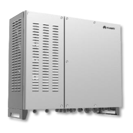
Page 15: Appearance
(2) Main cabinet door Only PID modules can be installed in the PID cabinet. Third-party devices cannot be installed in the PID cabinet. Figure 2-4 Rear view (1) Mounting plate (2) Mounting bracket Issue 05 (2019-01-20) Copyright © Huawei Technologies Co., Ltd. - Page 16 SmartACU2000B smart array controller User Manual (with PID modules, 800 V AC) 2 Overview Cabinet Dimensions Figure 2-5 Cabinet dimensions Figure 2-6 Mounting bracket dimensions Issue 05 (2019-01-20) Copyright © Huawei Technologies Co., Ltd.
- Page 17 DO/AO DO/AO signal 5/4 in. 20–32 mm cable hole (0.79–1.26 in.) AI signal cable 5/4 in. 20–32 mm hole (0.79–1.26 in.) DI signal cable 3/4 in. 13–18 mm hole (0.51–0.71 in.) Issue 05 (2019-01-20) Copyright © Huawei Technologies Co., Ltd.
-
Page 18: Label Conventions
Labels Symbol Name Meaning Electric shock warning High voltage exists after label the device is powered on. Only qualified and trained electrical technicians are allowed to install and operate the device. Issue 05 (2019-01-20) Copyright © Huawei Technologies Co., Ltd. - Page 19 Nameplate The smart array controller is labeled with a nameplate that contains the model information, key technical specifications, and compliance symbols. Issue 05 (2019-01-20) Copyright © Huawei Technologies Co., Ltd.
- Page 20 America and Canada CSA certification standards. CE certification mark The device complies with Conformité Europé enne (CE) certification standards. Environmentally friendly The device is use period (EFUP) environmentally friendly for the specified period. Issue 05 (2019-01-20) Copyright © Huawei Technologies Co., Ltd.
-
Page 21: Product Composition
Table 2-4 describes the components. Figure 2-9 Component installation positions To highlight the involved area, the figure does not show the open door. Issue 05 (2019-01-20) Copyright © Huawei Technologies Co., Ltd. - Page 22 Uc = 680 V AC 20 kA/40 kA, 8/20 μs Three-phase SPD 2 Uc = 680 V AC 20 kA/40 kA, 8/20 μs Position for the LAN SWITCH switch PLC CCO PLC CCO01A PLC CCO Issue 05 (2019-01-20) Copyright © Huawei Technologies Co., Ltd.
- Page 23 EMI with a maximum load of 30 W. RS485 communications 12 P/supporting 1–2.5 mm JX01 terminal 18–14 AWG) cable connection PID02 SmartPID2000 PID02 PID01 SmartPID2000 PID01 Issue 05 (2019-01-20) Copyright © Huawei Technologies Co., Ltd.
- Page 24 (LAN) switch (SWITCH) ○ ● ○ ● PLC CCO ● ● ● ● PE bar ● ● ● ● SmartLogger200 0 (SmartLogger) ● ● ● ● Fiber adapter (OFA01, OFA02) Issue 05 (2019-01-20) Copyright © Huawei Technologies Co., Ltd.
- Page 25 ● indicates that this component is included in the model. ○ indicates that this component is not included in this model. For simplicity purposes, the preceding table lists only the components that you need to operate and reserved installation positions. Issue 05 (2019-01-20) Copyright © Huawei Technologies Co., Ltd.
-
Page 26: Working Principles
24 V DC input or output. Figure 2-10 Electrical conceptual diagram (for the smart array controller not supporting 24 V DC input or output with QF02 and QF04 circuit breakers) Issue 05 (2019-01-20) Copyright © Huawei Technologies Co., Ltd. - Page 27 24 V DC input and output. Figure 2-12 Electrical conceptual diagram (for the smart array controller supporting 24 V DC input and output) Issue 05 (2019-01-20) Copyright © Huawei Technologies Co., Ltd.
- Page 28 The figure displays only major components and cables and is for reference only. PLC communication mode − If a double-column transformer is used, use the smart array controller that supports the access of one PLC route. Issue 05 (2019-01-20) Copyright © Huawei Technologies Co., Ltd.
- Page 29 The SmartLogger connects to the box-type transformer, power meter, and other − devices that support Ethernet communication over Ethernet electrical ports. The smart array controller communicates with the plant monitoring system over a fiber ring network or 4G LTE network. Issue 05 (2019-01-20) Copyright © Huawei Technologies Co., Ltd.
- Page 30 If a double-column transformer is used, use the smart array controller with one PID module. If a dual-split transformer is used, use the smart array controller with two PID modules. Issue 05 (2019-01-20) Copyright © Huawei Technologies Co., Ltd.
-
Page 31: Configuration Scenario
Recommended Model or Source of Quantity Specifications Compon Smart LAN switch (optional) UT-H605 or ES1000 Purchased array from control Huawei Fitting Low-speed FTLF1323P1BTR-HW Purchased bag for optical from module Huawei fiber ring Issue 05 (2019-01-20) Copyright © Huawei Technologies Co., Ltd. - Page 32 800 V, the rated voltage of the MCCB should be greater than or equal to 800 V. Let-through energy ≤ 1.26 x 10 Recommended rated current: 32 A; number of poles: 3 Issue 05 (2019-01-20) Copyright © Huawei Technologies Co., Ltd.
- Page 33 OT-M4 terminals customer 20–18 AWG (18 s cable AWG) Cabinet PE Outdoor copper cable with an OT-M6 6–16 mm Prepared cable terminal by the customer 10–6 AWG (6 AWG) Issue 05 (2019-01-20) Copyright © Huawei Technologies Co., Ltd.
- Page 34 Connection through a tube: two 14–12 AWG (14 single-core outdoor copper cables AWG) Operating voltage to the ground ≥ 300 V Issue 05 (2019-01-20) Copyright © Huawei Technologies Co., Ltd.
-
Page 35: Lte Network
Table 2-8 Components required in the 4G LTE network scenario Location Component Recommended Model or Source Quantity Specifications Compon Smart array LAN switch (optional) UT-H605 or ES1000 Purchased controller from Huawei POE and Purchased CPE fitting module from bags Huawei Issue 05 (2019-01-20) Copyright © Huawei Technologies Co., Ltd. - Page 36 Recommended rated current of the fuse: 32 A; rated current of the knife fuse switch box ≥ 32 A; number of poles: 3 (3 fuses for each knife fuse switch box) Issue 05 (2019-01-20) Copyright © Huawei Technologies Co., Ltd.
- Page 37 800 V, the rated voltage of the MCCB should be greater than or equal to 800 Let-through energy ≤ 1.26 x Recommended rated current: 32 A; number of poles: 3 Issue 05 (2019-01-20) Copyright © Huawei Technologies Co., Ltd.
- Page 38 OT-M4 terminals customer 20–18 AWG (18 s cable AWG) Cabinet PE Outdoor copper cable with an OT-M6 terminal 6–16 mm Prepared cable by the customer 10–6 AWG (6 AWG) Issue 05 (2019-01-20) Copyright © Huawei Technologies Co., Ltd.
- Page 39 Connection through a tube: two single-core 14–12 AWG (14 outdoor copper cables AWG) Operating voltage to the ground ≥ 300 V Issue 05 (2019-01-20) Copyright © Huawei Technologies Co., Ltd.
-
Page 40: Storage
If the smart array controller has been long-term stored, inspections and tests should be conducted by professionals before it is put into use. Huawei shall not be liable for any consequence caused by violation of the storage regulations specified in this document. -
Page 41: Installation
After unpacking the smart array controller, check whether the cabinet and fittings are intact and complete. If any damage is found or any component is missing, contact the dealer. For the number of delivered fittings, see the packing list in the packing case. Issue 05 (2019-01-20) Copyright © Huawei Technologies Co., Ltd. -
Page 42: Tools
Work with a torque Tightens bolts. wrench. Tightens nuts. Adjustable wrench Open end: 32 mm Tightens bolts. Torque wrench Tightens bolts. Tightens nuts. Diagonal pliers Cuts cable ties. Issue 05 (2019-01-20) Copyright © Huawei Technologies Co., Ltd. - Page 43 Wire stripper Peels cable jackets. Rubber mallet Hammers expansion bolts into holes. Utility knife Removes packaging. Cable cutter Cuts power cables. Crimping tool Crimps cables. RJ45 crimping tool Crimps RJ45 connectors. Issue 05 (2019-01-20) Copyright © Huawei Technologies Co., Ltd.
- Page 44 Wraps the cable crimping area of an OT terminal. Heat gun Blows a heat shrink tubing. Vacuum cleaner Cleans up dust after holes are drilling in a wall. Multimeter Measures voltages. Marker Marks positions. Issue 05 (2019-01-20) Copyright © Huawei Technologies Co., Ltd.
- Page 45 Protects your hands during installation. Operating voltage ≥ 2000 Insulation gloves Protects you from electric shocks. Safety goggles Protects your eyes during drilling. Anti-dust respirator Protects you from dust during hole drilling. Issue 05 (2019-01-20) Copyright © Huawei Technologies Co., Ltd.
-
Page 46: Determining The Installation Position
Do not install the smart array controller on flammable building materials. Ensure that the installation surface is solid enough to bear the smart array controller. For the weight details about the smart array controller, see 8 Technical Specifications. Issue 05 (2019-01-20) Copyright © Huawei Technologies Co., Ltd. -
Page 47: Installing The Mounting Bracket
The mounting bracket has four groups of tapped holes, each group containing four tapped holes. Mark any hole in each group based on site requirements and mark four holes in total. Two round holes are preferred. Issue 05 (2019-01-20) Copyright © Huawei Technologies Co., Ltd. -
Page 48: Wall-Mounted Installation
Step 1 Determine the positions for drilling holes using the mounting bracket. Level the hole positions using a level, and mark mounting holes using a marker. Figure 4-3 Determining hole positions Step 2 Drill holes using a hammer drill and install expansion bolts. Issue 05 (2019-01-20) Copyright © Huawei Technologies Co., Ltd. - Page 49 Remove the nut, spring washer, and flat washer. Step 3 Align the mounting bracket holes with the drilled holes, insert expansion bolts into the holes through the mounting bracket, and then tighten the expansion bolts. Issue 05 (2019-01-20) Copyright © Huawei Technologies Co., Ltd.
-
Page 50: Support-Mounted Installation
Step 1 Determine the positions for drilling holes using the mounting bracket. Level the hole positions using a level, and mark mounting holes using a marker. Figure 4-6 Determining hole positions Step 2 Drill holes using a hammer drill. Issue 05 (2019-01-20) Copyright © Huawei Technologies Co., Ltd. - Page 51 Step 3 Align the mounting bracket with the holes, insert the M12 × 40 bolt assembly delivered with the cabinet into the hole through the mounting bracket, and secure the bolt using the nut and flat washer delivered with the cabinet. Figure 4-8 Securing a mounting bracket Issue 05 (2019-01-20) Copyright © Huawei Technologies Co., Ltd.
-
Page 52: Pole-Mounted Installation
Step 2 Align the mounting bracket with the holes, insert the M12 × 40 bolt assembly delivered with the cabinet into the hole through the mounting bracket, and secure the bolt using the nut and flat washer delivered with the cabinet. Issue 05 (2019-01-20) Copyright © Huawei Technologies Co., Ltd. -
Page 53: Installing The Cabinet
4.5 Installing the Cabinet Procedure Step 1 Assign four persons to lift the cabinet and mount it onto the mounting bracket. Ensure that the cabinet is level with the mounting bracket. Issue 05 (2019-01-20) Copyright © Huawei Technologies Co., Ltd. - Page 54 Figure 4-11 Mounting a cabinet onto a mounting bracket Step 2 Remove the security torx wrench bound to the cabinet base and use the wrench to tighten security torx screws. Figure 4-12 Tightening security torx screws ----End Issue 05 (2019-01-20) Copyright © Huawei Technologies Co., Ltd.
-
Page 55: Opening The Main Cabinet Door
Do not leave unused screws in the cabinet. Procedure Step 1 Loosen the screws on the main cabinet. Figure 4-13 Loosening screws Step 2 Open the main cabinet door and use the support bar to stabilize the door. Issue 05 (2019-01-20) Copyright © Huawei Technologies Co., Ltd. -
Page 56: Installing Components
Step 3 Place the POE module at the installation position and align the mounting holes. Then secure the POE module. Indicators should be in the lower left corner. Step 4 Secure the mounting board. Issue 05 (2019-01-20) Copyright © Huawei Technologies Co., Ltd. -
Page 57: Optional) Installing The Poe Spd
Step 4 Place the POE SPD in the mounting bracket. Ensure that the PE point faces upwards and the surface marked PE faces outwards. Step 5 Secure the POE SPD fastener. Step 6 Connect the other end of the ground cable to the PE bar. Issue 05 (2019-01-20) Copyright © Huawei Technologies Co., Ltd. -
Page 58: Optional) Installing The Lan Switch
4.7.3 (Optional) Installing the LAN Switch Procedure Step 1 Take off the panel behind which a LAN switch will be installed. Step 2 Secure the LAN switch. Step 3 Connect the LAN switch PE cable. Issue 05 (2019-01-20) Copyright © Huawei Technologies Co., Ltd. - Page 59 SmartACU2000B smart array controller User Manual (with PID modules, 800 V AC) 4 Installation Figure 4-17 Installing a LAN switch ----End Issue 05 (2019-01-20) Copyright © Huawei Technologies Co., Ltd.
-
Page 60: Electrical Connections
Procedure (Common Connection) If you choose common connection, ensure that the appropriate cable is available. Step 1 Remove the locking cap and plug from the waterproof connector. Issue 05 (2019-01-20) Copyright © Huawei Technologies Co., Ltd. - Page 61 Prepare appropriate tubes based on the diameters of bottom cable holes. It is recommended that the tube specifications comply with the waterproof connector specifications. For example, for a 3/4 in. waterproof connector, a 3/4 in. tube is recommended. Issue 05 (2019-01-20) Copyright © Huawei Technologies Co., Ltd.
- Page 62 Step 1 Remove the locking cap and plug from the waterproof connector, and then remove the waterproof connector. Step 2 Secure the tube fitting using the nut delivered with the tube. Issue 05 (2019-01-20) Copyright © Huawei Technologies Co., Ltd.
-
Page 63: Preparing Cables
Step 7 Clear foreign matter from the cabinet. ----End 5.2 Preparing Cables The cables used for the smart array controller need to be prepared by yourself. Prepare cables by following the instructions in 2.6 Configuration Scenario. Issue 05 (2019-01-20) Copyright © Huawei Technologies Co., Ltd. -
Page 64: Crimping The Ot Terminal
Wrap the wire crimping area with heat shrink tubing or PVC insulation tape. The following figure uses heat shrink tubing as an example. When using the heat gun, protect devices from being scorched. Figure 5-5 Crimping an OT terminal Issue 05 (2019-01-20) Copyright © Huawei Technologies Co., Ltd. -
Page 65: Connecting The Cabinet Pe Cable
Figure 5-6 Connecting a PGND cable ----End Follow-up Procedure To enhance the corrosion resistance of a ground terminal, you are advised to apply silica gel or paint on it after connecting the ground cable. Issue 05 (2019-01-20) Copyright © Huawei Technologies Co., Ltd. -
Page 66: Connecting Communications Cables For The Fiber Ring Network
SFP1 port faces upwards, whereas the label of the low-speed optical module on the SFP2 port faces downwards. Step 2 Connect factory-installed optical jumpers to the low-speed optical modules. Issue 05 (2019-01-20) Copyright © Huawei Technologies Co., Ltd. -
Page 67: Connecting Cables To The Atb
As optical cables are hard, prepare optical cables before routing them into the smart array controller. Only professionals are allowed to connect optical cables. Connect two optical cables in a ring optical network, and connect one optical cable in a star optical network. Issue 05 (2019-01-20) Copyright © Huawei Technologies Co., Ltd. - Page 68 ATB interior. Figure 5-8 ATB interior (1) Fiber spool (2) Fixing points for internal steel wires of optical cables (3) Cable clip Procedure Step 1 Remove the ATB cover. Issue 05 (2019-01-20) Copyright © Huawei Technologies Co., Ltd.
- Page 69 SmartACU2000B smart array controller User Manual (with PID modules, 800 V AC) 5 Electrical Connections Figure 5-9 Removing a cover Step 2 Remove the optical cable fastener. Issue 05 (2019-01-20) Copyright © Huawei Technologies Co., Ltd.
- Page 70 Step 5 Connect the peripheral optical cable to the ATB, splice the optical cable and the optical jumper, and then wind the spliced cable around the fiber spool on the ATB. Only professionals are allowed to splice fibers. Issue 05 (2019-01-20) Copyright © Huawei Technologies Co., Ltd.
-
Page 71: Connecting The 4G Lte Cable (With The Poe Spd)
POE module. Procedure Step 1 Connect the POE port on the POE module to the PROTECT port on the POE SPD using the network cable delivered with the POE SPD. Issue 05 (2019-01-20) Copyright © Huawei Technologies Co., Ltd. - Page 72 Figure 5-12 Connecting a POE module to a POE SPD Step 2 Connect the factory-installed network cable to the DATA port on the POE module. Step 3 Connect the factory-installed power cable to the POE module. Issue 05 (2019-01-20) Copyright © Huawei Technologies Co., Ltd.
- Page 73 SmartACU2000B smart array controller User Manual (with PID modules, 800 V AC) 5 Electrical Connections Figure 5-13 Connecting cables Step 4 Connect the CPE network cable to the Surge port on the POE SPD. Issue 05 (2019-01-20) Copyright © Huawei Technologies Co., Ltd.
-
Page 74: Connecting The 4G Lte Cable (With No Poe Spd)
POE module. Procedure Step 1 Connect the factory-installed network cable to the DATA port on the POE module. Step 2 Connect the factory-installed power cable to the POE module. Issue 05 (2019-01-20) Copyright © Huawei Technologies Co., Ltd. - Page 75 5 Electrical Connections Figure 5-15 Connecting the POE module cable Step 3 Connect the CPE network cable to the POE port on the POE module. Figure 5-16 Connecting the CPE network cable Issue 05 (2019-01-20) Copyright © Huawei Technologies Co., Ltd.
-
Page 76: Connecting The Three-Phase Ac Power Cable (A Circuit Breaker As The Three-Phase Input Switch)
Step 2 Crimp an OT terminal. Step 3 Connect the L1, L2, and L3 cables to the three-phase input switch, and the functional earthing cable to the functional earthing bar, as shown in Figure 5-18. Issue 05 (2019-01-20) Copyright © Huawei Technologies Co., Ltd. - Page 77 Ensure that the L1, L2, and L3 cables are connected in correct phase sequence. Do not mix up the cable to the FE01 port with the cable to the FE02 port. Step 4 Bundle the cables. Issue 05 (2019-01-20) Copyright © Huawei Technologies Co., Ltd.
-
Page 78: Connecting The Three-Phase Ac Power Cable (A Knife Fuse Switch As The Three-Phase Input Switch)
For the smart array controller with one PID module, connect the three-phase AC power cable to the FU01 switch, and the functional ground cable to the FE01 port on the functional ground bar. Issue 05 (2019-01-20) Copyright © Huawei Technologies Co., Ltd. - Page 79 Ensure that the L1, L2, and L3 cables are connected in correct phase sequence. Do not mix up the cable to the FE01 port with the cable to the FE02 port. Step 4 Bundle the cables. Issue 05 (2019-01-20) Copyright © Huawei Technologies Co., Ltd.
-
Page 80: Connecting Peripheral Rs485 Communications Cables
5.10 Connecting Peripheral RS485 Communications Cables Context Connect peripheral RS485 communications cables to JX01. All RS485 communications cables are connected in the same way. This section describes how to connect two RS485 communications cables. Issue 05 (2019-01-20) Copyright © Huawei Technologies Co., Ltd. - Page 81 Step 2 Connect the communications cables to the JX01 terminal block. Step 3 Crimp an OT terminal on the shield layer, and then connect the shield layer to the cabinet ground point. Step 4 Bind the communications cables. Issue 05 (2019-01-20) Copyright © Huawei Technologies Co., Ltd.
-
Page 82: Connecting The Lan Switch Cable
Step 2 Connect the factory-installed power cable to the LAN switch. Connect the SWITCH-12V+ cable to the V+ power port on the LAN switch, and the SWITCH-12V– cable to the V– power port on the LAN switch. Issue 05 (2019-01-20) Copyright © Huawei Technologies Co., Ltd. -
Page 83: Connecting The Peripheral Network Cable
5.12 Connecting the Peripheral Network Cable Prerequisites Prepare a network cable, as shown in Figure 5-24. Figure 5-24 Connecting wires to an RJ45 connector (1) White-and-orange (2) Orange (3) White-and-green (4) Blue Issue 05 (2019-01-20) Copyright © Huawei Technologies Co., Ltd. - Page 84 This section describes how to connect one network cable. Procedure Step 1 Connect the peripheral network cable to the FE2 port on the LAN switch. Step 2 Bind the network cable. Figure 5-25 Connecting a network cable ----End Issue 05 (2019-01-20) Copyright © Huawei Technologies Co., Ltd.
-
Page 85: Connecting The 24 V Dc Output Power Cable
Figure 5-26 Stripped cable length Step 2 Connect the 24 V DC output power cable to the JX02 terminal block. Do not connect the DC output power cable reversely. Step 3 Bind cables. Issue 05 (2019-01-20) Copyright © Huawei Technologies Co., Ltd. -
Page 86: Connecting The 24 V Dc Input Power Cable
Port on the JX02 Terminal Definition Block 24VIN+ Positive terminal of the 24 V DC input power cable 24VIN– Negative terminal of the 24 V DC input power cable Procedure Step 1 Prepare cables. Issue 05 (2019-01-20) Copyright © Huawei Technologies Co., Ltd. -
Page 87: Connecting The Single-Phase Ac Power Cable
Do not connect the DC input power cable reversely. Step 3 Bind cables. Figure 5-29 Connecting cables ----End 5.15 Connecting the Single-Phase AC Power Cable Procedure Step 1 Prepare a cable. Issue 05 (2019-01-20) Copyright © Huawei Technologies Co., Ltd. -
Page 88: Connecting The Do/Ao/Di/Ai Signal Cable
The smart array controller reserves the PID01_DO, PID02_DO, DO, AO, DI, and AI waterproof connectors for appropriate signal cables. For details about how to prepare and connect the cables, see the SmartPID2000 User Manual and SmartLogger2000 User Manual. Issue 05 (2019-01-20) Copyright © Huawei Technologies Co., Ltd. - Page 89 SmartACU2000B smart array controller User Manual (with PID modules, 800 V AC) 5 Electrical Connections Figure 5-32 Cable routes Issue 05 (2019-01-20) Copyright © Huawei Technologies Co., Ltd.
-
Page 90: System Commissioning
The power voltage of the smart array controller is within the operating voltage range, and the three-phase input voltage is within the PLC/PID module operating voltage. All upstream switches for the smart array controller and all switches inside the cabinet are OFF. Issue 05 (2019-01-20) Copyright © Huawei Technologies Co., Ltd. -
Page 91: Closing The Main Cabinet Door
SmartLogger2000 User Manual. The LAN switch can be directly put into use without commissioning after power-on. 6.3 Closing the main Cabinet Door Prerequisites All components are running properly. Issue 05 (2019-01-20) Copyright © Huawei Technologies Co., Ltd. - Page 92 If the screws used for securing the cabinet door are lost, use the security torx screws in the fitting bag. If the floating nuts used for securing the cabinet door are lost, use the reserved floating nuts shown Figure 6-3. Issue 05 (2019-01-20) Copyright © Huawei Technologies Co., Ltd.
-
Page 93: Powering Off The System
Step 3 Turn off the DC input and output switches on the smart array controller. If the smart array controller does not support 24 V DC input or output, skip this step. Issue 05 (2019-01-20) Copyright © Huawei Technologies Co., Ltd. - Page 94 If the smart array controller houses one PID module, turn off the QF03 PID switch. If the smart array controller houses two PID modules, turn off the QF03 and QF05 PID switches. ----End Issue 05 (2019-01-20) Copyright © Huawei Technologies Co., Ltd.
-
Page 95: System Maintenance
Idle waterproof connectors are plugged and the locking caps are tightened. The cover on the USB port is tightened. Groundin All ground cables are reliably connected. Once 12 months reliability Issue 05 (2019-01-20) Copyright © Huawei Technologies Co., Ltd. -
Page 96: Troubleshooting
2. Check whether power is available 2. The power grid is disconnected to the power grid. from power. 3. Contact the dealer or Huawei 3. The PID module is faulty. technical support. 1. The power supply to the upstream 1. Use a multimeter to check... -
Page 97: Component Replacement
AC socket. 4. The power adapter is faulty. 4. Replace the power adapter. 5. The SmartLogger is faulty. 5. Contact the dealer or Huawei technical support. 7.3 Component Replacement Before replacing a component, power off the smart array controller by following the instructions in 6.4 Powering Off the System... -
Page 98: Replacing The Three-Phase Input Switch (Circuit Breaker)
Step 1 Remove the protective cover from the wiring terminals on the faulty three-phase input switch. Step 2 Disconnect cables from the faulty three-phase input switch, and label the cables. Step 3 Remove the wiring nuts from both sides at the bottom. Issue 05 (2019-01-20) Copyright © Huawei Technologies Co., Ltd. -
Page 99: Replacing The Three-Phase Input Switch (Knife Fuse Switch)
7.3.3 Replacing the Three-Phase Input Switch (Knife Fuse Switch) Prerequisites The three-phase input switch is faulty. A spare three-phase input switch of the same model is available and functional. Issue 05 (2019-01-20) Copyright © Huawei Technologies Co., Ltd. -
Page 100: Replacing The Fuse Of The Knife Fuse Switch
The fuse is faulty. There is a spare fuse provided by the knife fuse switch manufacturer. Procedure Step 1 Open the knife fuse switch box. Step 2 Remove the faulty fuse. Issue 05 (2019-01-20) Copyright © Huawei Technologies Co., Ltd. -
Page 101: Replacing The Single-Phase Input Switch
Figure 7-6 Removing a faulty single-phase input switch Step 3 Install the new single-phase input switch. Step 4 Connect the cables to the new single-phase input switch based on the cable labels. ----End Issue 05 (2019-01-20) Copyright © Huawei Technologies Co., Ltd. -
Page 102: Replacing The Plc Cco Module
A spare SmartLogger2000 of the same model is available and functional. Procedure Step 1 Disconnect cables from the faulty SmartLogger2000, and label the cables. Step 2 Remove the tray from the faulty SmartLogger2000. Issue 05 (2019-01-20) Copyright © Huawei Technologies Co., Ltd. - Page 103 Figure 7-9 Removing mounting ears Step 4 Install the tray on the new SmartLogger2000. Step 5 Install the new SmartLogger2000. Step 6 Connect the cables to the new SmartLogger2000 based on the cable labels. ----End Issue 05 (2019-01-20) Copyright © Huawei Technologies Co., Ltd.
-
Page 104: Replacing The Power Adapter
Step 6 Connect the output power cable for the power adapter to the power input port on the SmartLogger2000. ----End 7.3.9 Replacing the PID Switch Prerequisites The PID switch is faulty. Issue 05 (2019-01-20) Copyright © Huawei Technologies Co., Ltd. - Page 105 Step 3 Disconnect cables from the faulty PID switch, and label the cables. Step 4 Connect the cables to the new PID switch based on the cable labels. Step 5 Install the new PID switch. Step 6 Reinstall the PID switch fastener. ----End Issue 05 (2019-01-20) Copyright © Huawei Technologies Co., Ltd.
-
Page 106: Replacing The Pid Module
Step 1 Open the PID module cabinet door and install the support bar. Figure 7-13 Installing a support bar Step 2 Open the PID module maintenance compartment door, and remove the connection box cover. Issue 05 (2019-01-20) Copyright © Huawei Technologies Co., Ltd. - Page 107 Step 3 Disconnect cables from the faulty PID module, and label the cables. Step 4 Remove the pipe connector from the faulty PID module. Step 5 Remove the faulty PID module. Figure 7-15 Removing a PID module Issue 05 (2019-01-20) Copyright © Huawei Technologies Co., Ltd.
-
Page 108: Replacing The 24 V Dc Power Module
Step 3 Install the fastener on the new 24 V DC power module. Step 4 Install the new 24 V DC power module. Step 5 Connect the cables to the new 24 V DC power module based on the cable labels. Issue 05 (2019-01-20) Copyright © Huawei Technologies Co., Ltd. -
Page 109: Replacing The Fiber Adapter
A spare USB port of the same model is available and functional. Procedure Step 1 Disconnect the cable from the USB port, and label the cable. Step 2 Remove the faulty USB port. Issue 05 (2019-01-20) Copyright © Huawei Technologies Co., Ltd. - Page 110 Place the sealing ring on the inner side of the cabinet when installing the new USB port. Figure 7-19 Sealing ring position (1) sealing ring Step 4 Connect the cable to the new USB port based on the cable labels. Issue 05 (2019-01-20) Copyright © Huawei Technologies Co., Ltd.
-
Page 111: Replacing The 24 V Dc Input And Output Switches
Figure 7-20 Removing a faulty 24 V DC input switch Step 3 Install the new 24 V DC input switch. Step 4 Connect the cables to the new 24 V DC input switch based on the cable labels. ----End Issue 05 (2019-01-20) Copyright © Huawei Technologies Co., Ltd. -
Page 112: Technical Specifications
DC input 24–28 V DC, 70 W 24–28 V DC, 70 W (maximum) (maximum) DC output 24 V DC, 30 W 24 V DC, 30 W (maximum) (maximum) Frequency 50 Hz/60 Hz Issue 05 (2019-01-20) Copyright © Huawei Technologies Co., Ltd. - Page 113 Note b: For the smart array controller that supports 24 V DC input or output, the input range is between 100 V AC and 240 V AC or between 24 V DC and 28 V DC. Issue 05 (2019-01-20) Copyright © Huawei Technologies Co., Ltd.
-
Page 114: A Configuring The Di7 And Di8 Ports
Enable Alarm Name 24V power failure Table A-2 DI8 port parameter settings Parameter Value Parameter Value Activation Status Activated Alarm Severity Major Alarm Generation Enable Alarm Name AC SPD fault ----End Issue 05 (2019-01-20) Copyright © Huawei Technologies Co., Ltd. -
Page 115: B Configuring The Com1 Port And Com2 Port
Step 2 Choose Settings > RS485, and set the baud rate of the RS485-1 and RS485-2 port to 115200. Ensure that the start address of each port from RS485-1 to RS485-6 is 1, and the end address of the each port is 247. ----End Issue 05 (2019-01-20) Copyright © Huawei Technologies Co., Ltd. - Page 116 This device complies with part 15 of the FCC Rules. Operation is subject to the following two conditions: (1) This device may not cause harmful interference, and (2) this device must accept any interference received, including interference that may cause undesired operation. Issue 05 (2019-01-20) Copyright © Huawei Technologies Co., Ltd.
- Page 117 CAT 5E Category 5 enhanced central controller customer-premises equipment direct current digital input digital output environmental monitoring instrument Ethernet Long Term Evolution Issue 05 (2019-01-20) Copyright © Huawei Technologies Co., Ltd.
- Page 118 User Manual (with PID modules, 800 V AC) D Acronyms and Abbreviations protective earthing potential induced degradation power line communication power over Ethernet relative humidity small form-factor pluggable surge protective device WEEE waste electrical and electronic equipment Issue 05 (2019-01-20) Copyright © Huawei Technologies Co., Ltd.