Mitsubishi Electric MELSEC-Q Series User Manual
Simple motion module
Hide thumbs
Also See for MELSEC-Q Series:
- User manual (834 pages) ,
- Reference manual (674 pages) ,
- Programming manual (624 pages)

Related Manuals for Mitsubishi Electric MELSEC-Q Series


Summary of Contents for Mitsubishi Electric MELSEC-Q Series
- Page 1 MELSEC-Q QD77GF Simple Motion Module User's Manual (Network) -QD77GF4 -QD77GF8 -QD77GF16...
-
Page 3: Safety Precautions
SAFETY PRECAUTIONS (Please read these instructions before using this equipment.) Before using this product, please read this manual and the relevant manuals introduced in this manual carefully and pay full attention to safety to handle the product correctly. The precautions given in this manual are concerned with this product only. - Page 4 For Safe Operations 1. Prevention of electric shocks DANGER Never open the front case or terminal covers while the power is ON or the unit is running, as this may lead to electric shocks. Never run the unit with the front case or terminal cover removed. The high voltage terminal and charged sections will be exposed and may lead to electric shocks.
- Page 5 3. For injury prevention CAUTION Do not apply a voltage other than that specified in the instruction manual on any terminal. Doing so may lead to destruction or damage. Do not mistake the terminal connections, as this may lead to destruction or damage. Do not mistake the polarity (+/-), as this may lead to destruction or damage.
- Page 6 CAUTION The system must have a mechanical allowance so that the machine itself can stop even if the stroke limits switch is passed through at the max. speed. Use wires and cables that have a wire diameter, heat resistance and bending resistance compatible with the system.
- Page 7 DANGER The input devices and data registers assigned to the link will hold the data previous to when communication is terminated by an error, etc. Thus, an error correspondence interlock program specified in the instruction manual must be used. Use the interlock program specified in the intelligent function module's instruction manual for the program corresponding to the intelligent function module.
- Page 8 CAUTION Transport the product with the correct method according to the mass. Use the servomotor suspension bolts only for the transportation of the servomotor. Do not transport the servomotor with machine installed on it. Do not stack products past the limit. When transporting the module or servo amplifier, never hold the connected wires or cables.
- Page 9 CAUTION When not using the module for a long time, disconnect the power line from the module or servo amplifier. Place the module and servo amplifier in static electricity preventing vinyl bags and store. When storing for a long time, please contact with our sales representative. Also, execute a trial operation.
- Page 10 CAUTION Correctly and securely wire the wires. Reconfirm the connections for mistakes and the terminal screws for tightness after wiring. Failing to do so may lead to run away of the servomotor. After wiring, install the protective covers such as the terminal covers to the original positions. Do not install a phase advancing capacitor, surge absorber or radio noise filter (option FR-BIF) on the output side of the servo amplifier.
- Page 11 (5) Trial operation and adjustment CAUTION Confirm and adjust the program and each parameter before operation. Unpredictable movements may occur depending on the machine. Extreme adjustments and changes may lead to unstable operation, so never make them. When using the absolute position system function, on starting up, and when the module or absolute position motor has been replaced, always perform a home position return.
- Page 12 (7) Corrective actions for errors CAUTION If an error occurs in the self diagnosis of the module or servo amplifier, confirm the check details according to the instruction manual, and restore the operation. If a dangerous state is predicted in case of a power failure or product failure, use a servomotor with electromagnetic brakes or install a brake mechanism externally.
- Page 13 CAUTION Before performing online operations (especially, program modification, forced output, and operating status change) for the running CPU module on another station from GX Works2 over CC-Link IE Field Network, read relevant manuals carefully and ensure the safety. Improper operation may damage machines or cause accidents. Do not disassemble or modify the modules.
- Page 14 CAUTION When the module or absolute position motor has been replaced, carry out a home position return operation using one of the following methods, otherwise position displacement could occur. 1) After writing the servo data to the Simple Motion module using programming software, switch on the power again, then perform a home position return operation.
-
Page 15: Conditions Of Use For The Product
CONDITIONS OF USE FOR THE PRODUCT (1) Mitsubishi programmable controller ("the PRODUCT") shall be used in conditions; i) where any problem, fault or failure occurring in the PRODUCT, if any, shall not lead to any major or serious accident; and ii) where the backup and fail-safe function are systematically or automatically provided outside of the PRODUCT for the case of any problem, fault or failure occurring in the PRODUCT. -
Page 16: Introduction
Field Network Simple Motion module (hereafter abbreviated as master/local module). Before using this product, please read this manual and the relevant manuals carefully and develop familiarity with the functions and performance of the MELSEC-Q series programmable controller to handle the product correctly. -
Page 17: Revisions
This manual confers no industrial property rights or any rights of any other kind, nor does it confer any patent licenses. Mitsubishi Electric Corporation cannot be held responsible for any problems involving industrial property rights which may occur as a result of using the contents noted in this manual. -
Page 18: Table Of Contents
CONTENTS SAFETY PRECAUTIONS ..........................A- 1 CONDITIONS OF USE FOR THE PRODUCT ..................... A-13 INTRODUCTION ............................A-14 REVISIONS ..............................A-15 CONTENTS ..............................A-16 COMPLIANCE WITH THE EMC AND LOW VOLTAGE DIRECTIVES ............A-19 RELEVANT MANUALS ..........................A-20 MANUAL PAGE ORGANIZATION ........................ A-22 TERMS ................................ - Page 19 6. INSTALLATION AND WIRING 6- 1 to 6- 2 6.1 Installation and Wiring ..........................6- 2 7. PARAMETER SETTING 7- 1 to 7-30 7.1 Parameter and Backup ..........................7- 2 7.2 Parameter List ............................7- 3 7.3 Network Settings ............................7- 5 7.4 Network Configuration Settings .......................
- Page 20 10.6 JP/GP.WRITE (Writing Data to Another Station) ................10-22 10.7 JP/GP.SWRITE (Writing Data to Another Station) ................10-33 10.8 ZP.REMFR (Reading Data from the Intelligent Device Station/Remote Device Station) ....10-39 10.9 ZP.REMTO (Writing Data to the Intelligent Device Station/Remote Device Station) ......10-44 11.
-
Page 21: Compliance With The Emc And Low Voltage Directives
COMPLIANCE WITH THE EMC AND LOW VOLTAGE DIRECTIVES (1) Method of ensuring compliance To ensure that Mitsubishi programmable controllers maintain EMC and Low Voltage Directives when incorporated into other machinery or equipment, certain measures may be necessary. Please refer to one of the following manuals. •... -
Page 22: Relevant Manuals
MELSEC-Q QD77GF Simple Motion Module User's Manual Overview of CC-Link IE Field Network, and specifications, (Network) procedures before operation, system configuration, installation, wiring, settings, functions, programming, and troubleshooting of the MELSEC-Q series Simple Motion <IB-0300203, 1XB957> module (2) CC-Link IE Field Network Manual name Description <manual number (model code)>... - Page 23 (3) CPU module Manual name Description <manual number (model code)> QCPU User's Manual Specifications of the hardware (CPU modules, power supply (Hardware Design, Maintenance and Inspection) modules, base units, batteries, and memory cards), system <SH-080483ENG, 13JR73> maintenance and inspection, and troubleshooting QnUCPU User's Manual Functions and devices of the CPU module, and (Function Explanation, Program Fundamentals)
- Page 24 MANUAL PAGE ORGANIZATION The symbols used in this manual are shown below. A serial No. is inserted in the "*" mark. Symbol Description [Md. * ] Symbol that indicates monitor data item. Symbol that indicates specifications during the communication mode compatible with MR-J4-B-RJ010.
-
Page 25: Terms
TERMS Unless otherwise specified, this manual uses the following terms. Term Description QCPU Another term for the MELSEC-Q series CPU module LCPU Another term for the MELSEC-L series CPU module QSCPU Another term for the MELSEC-QS series CPU module QnACPU Another term for the MELSEC-QnA series CPU module A CPU module that controls connected I/O modules and intelligent function modules. - Page 26 Term Description A station reserved for future use. This station is not actually connected, but counted as a Reserved station connected station. A function by which data are periodically exchanged among stations on the same network Cyclic transmission using link devices (RX, RY, RWw, and RWr) A function of communication with another station, which is used when requested by a Transient transmission dedicated instruction or GX Works2...
- Page 27 Term Description READ The abbreviation for JP.READ and GP.READ SREAD The abbreviation for JP.SREAD and GP.SREAD WRITE The abbreviation for JP.WRITE and GP.WRITE SWRITE The abbreviation for JP.SWRITE and GP.SWRITE REMFR The abbreviation for ZP.REMFR REMTO The abbreviation for ZP.REMTO A - 25...
-
Page 28: Packing List
PACKING LIST The following items are included in the package of this product. Before use, check that all the items are included. (1) QD77GF4 QD77GF4 Before Using the Product (2) QD77GF8 QD77GF8 Before Using the Product (3) QD77GF16 QD77GF16 Before Using the Product A - 26... -
Page 29: Cc-Link Ie Field Network
Chapter 1 CC-LINK IE FIELD NETWORK Chapter 1 CC-LINK IE FIELD NETWORK 1.1 CC-Link IE Field Network ....................1- 2 1.2 Simple Motion Modules ....................1- 4 1 - 1... - Page 30 Chapter 1 CC-LINK IE FIELD NETWORK 1.1 CC-Link IE Field Network CC-Link IE Field Network is a high-speed and large-capacity open field network that is based on Ethernet technology (1000BASE-T). (1) Data communication High-speed and large-capacity data communication is available between a master station and slave stations on CC-Link IE Field Network.
- Page 31 Chapter 1 CC-LINK IE FIELD NETWORK (2) 1Gbps communication speed 1Gbps communication speed allows high-speed communication. Also, the cycle time can be reduced due to the improved performance of communication response. (3) Use of Ethernet cable A 1000BASE-T-compliant Ethernet is used for the connection interface. The wiring cost can be reduced because 1000BASE-T-compliant Ethernet cables are commercially available.
-
Page 32: Simple Motion Modules
Chapter 1 CC-LINK IE FIELD NETWORK 1.2 Simple Motion Modules A Simple Motion module is used to connect a servo amplifier or a MELSEC-Q series programmable controller to CC-Link IE Field Network. The module works as a master station on CC-Link IE Field Network. - Page 33 Chapter 1 CC-LINK IE FIELD NETWORK (3) Multiple axes system configuration (Note-1) The servo amplifiers can be controlled up to 16 axes . By connecting slave stations excluding servo amplifiers the system can be configured up to 120 axes (the number of axes that can be controlled +104 axes).
- Page 34 Chapter 1 CC-LINK IE FIELD NETWORK (5) Irregular communications with another station (transient transmission) Reading or writing data A Simple Motion module can access other stations by dedicated instructions. (Refer to Section 10.1.) CPU module Master station Intelligent device station Command READ Device...
- Page 35 Chapter 1 CC-LINK IE FIELD NETWORK Checking CC-Link IE Field Network status graphically The CC-Link IE Field Network status can be checked using GX Works2. Error locations, error causes, and event history are displayed on the window. This allows the system to quickly recover from errors. (Refer to Chapter 9.) 1 - 7...
- Page 36 Chapter 1 CC-LINK IE FIELD NETWORK (7) Adding CC-Link IE Field Network devices without stopping the system Adding CC-Link IE Field Network devices CC-Link IE Field Network devices whose parameters have not been set can be added without powering off the system. (Refer to the user's Manual of the head module.) Connection of an added module can be recognized, and setting a station No.
-
Page 37: Names Of Each Part
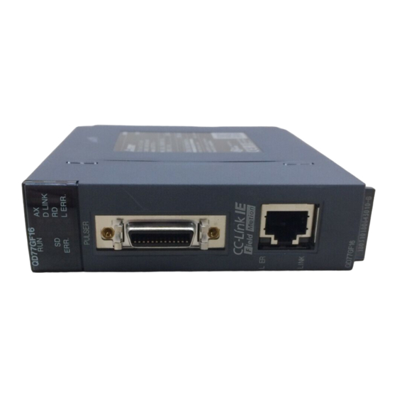
Chapter 2 NAMES OF EACH PART Chapter 2 NAMES OF EACH PART 2.1 Names of Each Part ....................... 2- 2 2 - 1... - Page 38 Chapter 2 NAMES OF EACH PART 2.1 Names of Each Part This chapter describes the names of each part of the Simple Motion module. QD77GF4 QD77GF8 QD77GF16 Name Description LED (upper part on the front) Refer to this section (1). LED (CC-Link IE Field connector section) Refer to this section (2).
- Page 39 Chapter 2 NAMES OF EACH PART (1) LED (upper part on the front) QD77GF4 QD77GF8 QD77GF16 QD77GF4 QD77GF8 QD77GF16 D LINK D LINK D LINK ERR. L ERR. ERR. L ERR. ERR. L ERR. LED Display Description LED Display Description D LINK Hardware failure, SD LED...
- Page 40 Chapter 2 NAMES OF EACH PART (2) CC-Link IE Field Network connector section L ER LINK LED Display Description L ER L ER LED is Receive data error LINK L ER L ER LED is Receive data operates normally. OFF. LINK L ER LINK LED is...
- Page 41 Chapter 3 SPECIFICATIONS Chapter 3 SPECIFICATIONS 3.1 General Specifications ....................3- 2 3.2 Performance Specifications ..................3- 2 3.3 Function List ........................3- 3 3.4 Specifications of Input/Output Signals with CPU Module ........... 3- 5 3.4.1 List of input/output signals with CPU module ..........3- 5 3.4.2 Details of input signals (Simple Motion module CPU module) ....
-
Page 42: Specifications
Chapter 3 SPECIFICATIONS This chapter describes the specifications, function list, I/O signal, and buffer memory of the Simple Motion module. 3.1 General Specifications For the general specifications of the Simple Motion module, refer to "MELSEC-Q QD77GF Simple Motion Module User's Manual (Positioning Control)". 3.2 Performance Specifications Performance specifications for the network function are shown below. -
Page 43: Function List
Chapter 3 SPECIFICATIONS 3.3 Function List Lists of network functions are shown below. (1) Basic functions Function Description Reference The slave device is communicated in the fixed cycle. The communication Fixed cycle communication Section 8.1 cycle is the same as an operation cycle of the Simple Motion module. The processing cycles of the Simple Motion module and each slave station Synchronous communication Section 8.2... - Page 44 Chapter 3 SPECIFICATIONS (3) Transient transmission Function Description Reference Communications within the same Transient transmission is performed to other stations using dedicated Chapter 10 network instructions and GX Works2. (4) Diagnostic functions Function Description Reference The status of CC-Link IE Field Network can be checked using GX Works2. CC-Link IE Field Network diagnostics The error locations, error causes, corrective actions, and event history can be Chapter 9...
-
Page 45: Specifications Of Input/Output Signals With Cpu Module
Chapter 3 SPECIFICATIONS 3.4 Specifications of Input/Output Signals with CPU Module 3.4.1 List of input/output signals with CPU module The Simple Motion module uses 32 input points and 32 output points for exchanging data with the CPU module. The input/output signals when the head I/O number of Simple Motion module is set to "0H" are shown below. -
Page 46: Details Of Input Signals (Simple Motion Module Cpu Module)
Chapter 3 SPECIFICATIONS Important [Y2 to YF] and [X2 to XE] are used by the system, and cannot be used by the user. If these devices are used, the operation of the Simple Motion module will not be guaranteed. 3.4.2 Details of input signals (Simple Motion module CPU module) The ON/OFF timing and conditions of the input signals are shown below. -
Page 47: Buffer Memory (Network Function)
Chapter 3 SPECIFICATIONS 3.5 Buffer Memory (Network Function) The buffer memory is used to exchange data between the Simple Motion module and the CPU module. Buffer memory values are defaulted when the CPU module is reset or the system is powered off. - Page 48 Chapter 3 SPECIFICATIONS Address (Decimal Name Initial value Read, write Refer to (Hexadecimal)) 63568 Station No.17 RWw offset (F850H) 63569 Station No.17 RWw size (F851H) RWw offset/size information Read Appendix 1.4 63774 Station No.120 RWw (F91EH) offset 63775 Station No.120 RWw size (F91FH) 63776 Station No.17 RWr offset...
-
Page 49: Procedures Before Operation
Chapter 4 PROCEDURES BEFORE OPERATION Chapter 4 PROCEDURES BEFORE OPERATION 4.1 Procedures Before Operation ..................4- 2 4 - 1... - Page 50 Chapter 4 PROCEDURES BEFORE OPERATION 4.1 Procedures Before Operation For the procedures before operation of the Simple Motion module, refer to "MELSEC-Q QD77GF Simple Motion Module User's Manual (Positioning Control)". 4 - 2...
-
Page 51: System Configuration
Chapter 5 SYSTEM CONFIGURATION Chapter 5 SYSTEM CONFIGURATION 5.1 CC-Link IE Field Network Configuration ..............5- 2 5.1.1 Single network system ..................5- 2 5.1.2 Precautions ....................... 5- 4 5.2 Network Components ..................... 5- 7 5.2.1 Cables ....................... 5- 7 5.2.2 Hubs ........................ -
Page 52: Cc-Link Ie Field Network Configuration
Chapter 5 SYSTEM CONFIGURATION 5.1 CC-Link IE Field Network Configuration This section describes CC-Link IE Field Network configurations. 5.1.1 Single network system (1) Overall system configuration A single network system is a system in which a Simple Motion module (master station) and slave stations are connected using Ethernet cables as shown below. - Page 53 Chapter 5 SYSTEM CONFIGURATION (2) Network configuration Network topology The network can be wired into star topology or line topology. A network can consist of a combination of star and line topologies. The Simple Motion module does not support the ring topology. Switching hub Star topology Line topology...
-
Page 54: Precautions
Chapter 5 SYSTEM CONFIGURATION Station number and connection position Modules can be connected in any order regardless of the station number. When the device transmits data, delay time will occur. Therefore, it is recommended to connect servo amplifiers adjacently. Station No.0 (Master station) Station No.17 Station No.19... - Page 55 Chapter 5 SYSTEM CONFIGURATION (3) Connecting/disconnecting a cable and powering off/on a device When the operations listed below are performed, a data link error may momentarily occur in all the stations and outputs of the connected slave stations may turn off since all stations on the network will be reconnected.
- Page 56 Chapter 5 SYSTEM CONFIGURATION (5) Connected station numbers Do not duplicate station numbers. Data link may be stopped when the station number is duplicated. Duplication Station No.0 Station No.17 Station No.17 Station No.18 (Data link may stop.) (6) Power-on order To avoid incorrect input from slave stations, power on slave stations before the master station.
-
Page 57: Network Components
• Cables for CC-Link IE Controller Network cannot be used for CC-Link IE Field Network. (1) Product Cables for CC-Link IE Field Network are available from Mitsubishi Electric System & Service Co., Ltd. (Catalogs for cable are also available.) Also, the connector processing of cable length is available for your preference. Please consult your local Mitsubishi Electric System &... -
Page 58: Applicable Systems
Chapter 5 SYSTEM CONFIGURATION 5.3 Applicable Systems For the MELSEC-Q series systems that include the Simple Motion module, refer to "MELSEC-Q QD77GF Simple Motion Module User's Manual (Positioning Control)". 5 - 8... -
Page 59: Installation And Wiring
Chapter 6 INSTALLATION AND WIRING Chapter 6 INSTALLATION AND WIRING 6.1 Installation and Wiring ....................6- 2 6 - 1... - Page 60 Chapter 6 INSTALLATION AND WIRING 6.1 Installation and Wiring For the installation and wiring of the Simple Motion module refer to the "MELSEC-Q QD77GF Simple Motion Module User's Manual (Positioning Control)". 6 - 2...
-
Page 61: Parameter Setting
Chapter 7 PARAMETER SETTING Chapter 7 PARAMETER SETTING 7.1 Parameter and Backup ....................7- 2 7.2 Parameter List ........................ 7- 3 7.3 Network Settings ......................7- 5 7.4 Network Configuration Settings ..................7- 8 7.5 Network Operation Settings ................... 7-20 7.6 Refresh Parameters ...................... -
Page 62: Parameter And Backup
Chapter 7 PARAMETER SETTING This chapter describes CC-Link IE Field Network parameters. The CC-Link IE Field Network parameters are set for either the master station or slave stations. This manual describes network parameters for Simple Motion modules. For slave station settings, refer to the manuals for the slave stations used. -
Page 63: Parameter List
Chapter 7 PARAMETER SETTING 7.2 Parameter List The following table lists CC-Link IE Field Network parameters. (1) Parameters set for a Simple Motion module When setting the parameters for the Simple Motion module, select "CC IE Field (Motion Master Station)" in Network Type using GX Works2. The parameters for the function not supported by the Simple Motion module are disabled. - Page 64 Chapter 7 PARAMETER SETTING Necessity of Item Reference setting Network Type Start I/O No. Network No. 1) Network setting Section 7.3 Total Stations Station No. – Mode Assignment Method Station No. Station Type RX/RY Setting RWw/RWr Setting Refresh Device – Reserved/Error Invalid Station Alias –...
-
Page 65: Network Settings
Chapter 7 PARAMETER SETTING 7.3 Network Settings Set the network number, station number, and other parameters for the Simple Motion module. (1) Setting procedure 1) Open the setting window. Project window [Parameter] [Network Parameter] [Ethernet/CC IE/MELSECNET] 2) Set parameters in the window. 3) Click the [End] button. - Page 66 Chapter 7 PARAMETER SETTING Item Description Setting range Remark Enter the start I/O number of the Simple Motion Within the number of I/O points of the Start I/O No. – module in increments of 16 points. CPU module (Default: Blank) Enter the network number of the Simple Motion Network No.
- Page 67 Chapter 7 PARAMETER SETTING Item Description Setting range Remark Set parameters of slave stations (the number of points and assignment of link devices) in the master station. When the checkbox next to "Set the network [Network Configuration configuration setting in the CC IE Field configuration Refer to Section 7.4.
-
Page 68: Network Configuration Settings
Chapter 7 PARAMETER SETTING 7.4 Network Configuration Settings Set parameters of slave stations (the number of points and assignment of link devices) in the master station. Set a link scan mode and block data assurance per station as well. Two methods are available for the network configuration settings as listed in the following table. - Page 69 Chapter 7 PARAMETER SETTING (1) Setting on the graphical window (CC IE Field configuration window) 1) Select the checkbox next to "Set the network configuration setting in the CC IE Field configuration window". (Refer to Section 7.2.) 2) Configure the network setting. (Refer to Section 7.3.) 3) Open the setting window.
- Page 70 Chapter 7 PARAMETER SETTING (a) Setting the configuration of the slave station in the master station Item Description Setting range Remark •If the value outside the setting range is set, "Parameter • Online (Normal Mode) Set the mode of the master station. (Refer to Section error (error code: Mode Setting •...
- Page 71 Chapter 7 PARAMETER SETTING Item Description Setting range Remark •If the value outside the setting range is set, one of the "Parameter error Assign RX/RY points to the station No.17 to 120. (error code: (Refer to Section 8.3.1.) • Points: D615H to Points can be assigned in increments of 16 (Start: Intelligent Device Station: 16 to 2048...
- Page 72 Chapter 7 PARAMETER SETTING Item Description Setting range Remark Set this item to reserve the slave station from the station No.17 to 120. (Refer to Section 8.5.) • No Setting •If the invalid The slave station is connected to the network. station is set, •...
- Page 73 Chapter 7 PARAMETER SETTING (c) Supplementary Setting [CC IE Field Configuration] [Supplementary Setting] Item Description Setting range Remark Set "Link Scan Mode Setting", "Loopback Function Setting", "Block Data Assurance per Station", and "Operation Setting for Returning". • Link Scan Mode Setting: All invalid.
- Page 74 Chapter 7 PARAMETER SETTING (d) Equal assignment and identical point assignment of link points [CC IE Field Configuration] [Equal Assignment] or [Identical Point Assignment] Item Description Setting range Remark Equally assign link devices to stations with preset conditions. • Start Station: 0 to the end station number •...
- Page 75 Chapter 7 PARAMETER SETTING (e) Parameter processing of a slave station [CC IE Field Configuration] after selecting the module in the station list area [Parameter Processing of Slave Station] The parameters of a slave station can be set or read. This can be performed when the slave station supports the parameter process.
- Page 76 Chapter 7 PARAMETER SETTING (2) Setting on the window in the table format 1) Set network setting parameters. (Refer to Section 7.3.) 2) Open the setting window. Project window [Parameter] [Network Parameter] [Ethernet/CC IE/MELSECNET] [Network Configuration Settings] button 3) Set parameters in the window. 4) Click the [End] button.
- Page 77 Chapter 7 PARAMETER SETTING Item Description Setting range Remark •If the value outside the setting range is set, one of the "Parameter error (error code: • Points: D615H to Assign RX/RY points to the station No.17 to 120. Intelligent Device Station: 16 to 2048 D618H)"...
- Page 78 Chapter 7 PARAMETER SETTING Item Description Setting range Remark Set this item to reserve the slave station from the station No.17 to 120. (Refer to Section 8.5.) • No Setting •If the error invalid The slave station is connected to the network. station is set, •...
- Page 79 Chapter 7 PARAMETER SETTING Item Description Setting range Remark Equally assign link devices to stations with preset conditions. • Start Station: 1 to the end station number • End Station: Number set to "Start Station" to the end station number [Equal Assignment] •...
-
Page 80: Network Operation Settings
Chapter 7 PARAMETER SETTING 7.5 Network Operation Settings Set operating status of a network if a data link error occurs or the CPU module is set to STOP. 1) Set network setting parameters. (Refer to Section 7.3.) 2) Open the setting window. Project window [Parameter] [Network Parameter]... -
Page 81: Refresh Parameters
Chapter 7 PARAMETER SETTING 7.6 Refresh Parameters Set link refresh ranges between the link devices of the Simple Motion module and the devices of the CPU module. (1) Setting procedure 1) Set network setting parameters. (Refer to Section 7.3.) 2) Open the setting window. Project window [Parameter] [Network Parameter]... - Page 82 Chapter 7 PARAMETER SETTING Item Description Setting range Remark • Link Side: RX, RY, RWr, RWw • PLC Side: When RX is set to Set the link refresh ranges of RX, RY, RWr, and RWw. Up to 256 "Link Side": ranges can be set.
- Page 83 Chapter 7 PARAMETER SETTING (2) Checking method 1) Click the [Assignment Image] button in the "Network Parameter - MELSECNET/CC IE/Ethernet Module Configuration" window to open the "Assignment Image" window. (Refer to Section 7.3.) 2) Select the devices to be checked and the magnification ratio in the window. 1) Click 2) Set "Device (PLC side)",...
- Page 84 Chapter 7 PARAMETER SETTING (3) Precautions Device set to "Device (PLC Side)" Set a device range that differs from the one used for the following: • Refresh parameters for other network modules • Auto refresh parameters for CC-Link master/local module •...
-
Page 85: Interrupt Settings
Chapter 7 PARAMETER SETTING 7.7 Interrupt Settings Set conditions for sending an interrupt request to the CPU module. (1) Setting procedure 1) Set network setting parameters. (Refer to Section 7.3.) 2) Open the setting window. Project window [Parameter] [Network Parameter] [Ethernet/CC IE/MELSECNET] [Interrupt Settings] button 3) Set parameters in the window. - Page 86 Chapter 7 PARAMETER SETTING (Setting range) Device Device Word Device Channel No./ Interrupt Detection Method Interrupt Condition Code Setting Value Connection No. (SI) No. 0H to Level Detect and ON : Interrupt occurs by turning 1FFFH on the device. Level Detect and OFF: Interrupt occurs by turning off 0H to the device.
- Page 87 Chapter 7 PARAMETER SETTING 6) Click the [End] button. Item Description Setting range Interrupt Pointer Start No. Enter the start number of an interrupt program (I 50 to 255 (Default: Blank) PLC Side Interrupt Pointer Count Enter the number of interrupt conditions. 1 to 16 (Default: Blank) 0000H to 0FE0H Start I/O No.
- Page 88 Chapter 7 PARAMETER SETTING Before executing an interrupt program Execute the EI instruction in a main routine program and enable an interrupt. (Refer to the user's Manual (Function Explanation, Program Fundamentals) for the CPU module used.) Enable interrupt Main routine program FEND I/O interrupt...
- Page 89 Chapter 7 PARAMETER SETTING (3) Setting example Starting the interrupt program of the master station (station number 0) when RX100 turns on The following is a setting example to execute the interrupt program corresponding to the interrupt pointer I50 when RX100 turns on by turning on the corresponding switch on the slave station side.
- Page 90 Chapter 7 PARAMETER SETTING Starting the interrupt program by an interrupt request to the CPU module in every operation cycle An interrupt request to the CPU module can be executed in every operation cycle by using Operation cycle interrupt request (SB000C) of link special relay (SB). Simple Motion module Master station CPU module...
-
Page 91: Functions
Chapter 8 FUNCTIONS Chapter 8 FUNCTIONS 8.1 Fixed Cycle Communication ..................8- 2 8.2 Synchronous Communication Function ................. 8- 2 8.3 Cyclic Transmission ....................... 8- 4 8.3.1 Data flow and link device assignment .............. 8- 4 8.3.2 Link refresh ....................... 8- 6 8.3.3 Direct access to link devices ................ -
Page 92: Fixed Cycle Communication
Chapter 8 FUNCTIONS This chapter explains the network functions of the Simple Motion module. 8.1 Fixed Cycle Communication The communication cycle of the Simple Motion module is fixed cycle. The communication is performed with slave modules in a cycle set in the operation cycle setting. 8.2 Synchronous Communication Function A slave module which supports the synchronous communication function operates synchronously with the operation cycle of the Simple Motion module (the communication... - Page 93 Chapter 8 FUNCTIONS POINT The synchronous communication function with slave modules excluding servo amplifiers is supported from the version shown below. (Note-1) First five digits of SERIAL No. Operation Slave modules operate in the normal mode Before 15092 (asynchronous communication mode). 15092 or later Slave modules operate following the setting.
-
Page 94: Cyclic Transmission
Chapter 8 FUNCTIONS 8.3 Cyclic Transmission Data communication is available periodically among stations on the same network. Link devices (RX, RY, RWr, and RWw) are used. 8.3.1 Data flow and link device assignment One-to-one communication is possible between the Simple Motion module (master station) and the connected device of the station No.17 to 120. - Page 95 Chapter 8 FUNCTIONS (Note-1) (1) Station No.1 to 16 • Output from the master station (a) The sending data calculated in the Simple Motion module is stored in the internal memory of the slave station in each communication cycle. The sending data to the slave stations are not stored in the link devices (RY and RWw).
-
Page 96: Link Refresh
Chapter 8 FUNCTIONS 8.3.2 Link refresh Data can be automatically transferred between the link devices of the Simple Motion module and the devices of the CPU module. Simple Motion module module Link Device device Link refresh (1) Concept of the link refresh range The area range set with the refresh parameters and also specified in the network configuration settings is executed by link refresh. - Page 97 Chapter 8 FUNCTIONS (4) Precautions For cyclic data assurance of more than 32 bits, use the following method. • Enable the Block Data Assurance per Station setting. (Refer to Section 7.4, Refer to Section 8.3.4.) POINT When the CPU module is turned off and on or reset, data in latched devices (the devices listed in the "CPU module device"...
-
Page 98: Direct Access To Link Devices
Chapter 8 FUNCTIONS 8.3.3 Direct access to link devices Direct access to each link device (RX, RY, RWr, RWw, SB, or SW) of the Simple Motion module is possible from the program. Specify a link device as the link direct device (J \ ) for direct access. - Page 99 Chapter 8 FUNCTIONS (2) Readable and writable range Data can be read or written between the Simple Motion module and CPU module mounted on the same base unit. Read All link devices of the Simple Motion module can be specified. (Refer to Section 8.3.3 (1).) Write The range that satisfies all of the following conditions can be specified.
- Page 100 Chapter 8 FUNCTIONS POINT When writing data to the area in the link refresh range, directly access the link device and write the same data in the device of the CPU module. Bad example (Only direct access to the link refresh target) CPU module Simple Motion module MOV K20 J1\W100...
- Page 101 Chapter 8 FUNCTIONS (3) Differences from link refresh Access method Item Link refresh Direct access Number of steps 1 step 2 steps (Note-1) Processing speed (LD B0 High speed (0.0095µs) Low speed (10 to 100µs) (Note-2) Station-based or 32-bit units Data reliability –...
-
Page 102: Assurance Of Cyclic Data Integrity
Chapter 8 FUNCTIONS 8.3.4 Assurance of cyclic data integrity The cyclic data integrity can be assured in 32-bit units or for each station. Assurance Method Description Link Direct access to Access to buffer refresh link devices memories Assures data in 32-bit units. 32-bit data Data is automatically assured by assurance... - Page 103 Chapter 8 FUNCTIONS Access to cyclic data When link devices are accessed, the integrity of 32-bit data can be assured by satisfying the following conditions. • When directly accessing link devices: The start device number of RWr/RWw is multiples of 2. The number of points assigned to RWr/RWw is multiples of 2.
- Page 104 Chapter 8 FUNCTIONS (2) Block data assurance per station Integrity of the cyclic data is assured for each station by handshake between the CPU module and Simple Motion module for a link refresh. Setting Enable "Block Data Assurance per Station" in "Network Configuration Settings" of the master station.
- Page 105 Chapter 8 FUNCTIONS Access to link devices During a link refresh, data are assured for each station as shown below. CPU module Simple Motion module Device Link device Data Station Station Data assurance No.17 No.17 assurance Data Station Station Data assurance No.18 No.18...
-
Page 106: Input And Output Status Settings In Case Of Failure
Chapter 8 FUNCTIONS 8.3.5 Input and output status settings in case of failure For the Simple Motion module, status of input from a data link faulty station and output status of cyclic data if a stop error occurs in the CPU module can be set. Status Range where the settings are enabled Clearing or holding the following RX input data can be selected. - Page 107 Chapter 8 FUNCTIONS (1) Setting method Input status of data link faulty station Set this item in the "Network Operation Settings" window. (Refer to Section 7.5.) Cyclic data output when a stop error occurs in the CPU module Select "PLC Parameter" and set it in "Intelligent Function Module Detailed Setting". [Project Window] [Parameter] [PLC Parameter]...
-
Page 108: Output Status Setting For Cpu Module Stop
Chapter 8 FUNCTIONS 8.3.6 Output status setting for CPU module STOP When the CPU module mounted with a Simple Motion module is set to STOP, whether cyclic data output is held or cleared can be selected. (1) Range where the setting becomes enabled The setting is fixed to hold or clear depending on devices set to link refresh, regardless of the output setting during CPU STOP. -
Page 109: Cyclic Transmission Stop And Restart
Chapter 8 FUNCTIONS 8.3.7 Cyclic transmission stop and restart During debugging and other operations, cyclic transmission is stopped. (Data reception from a slave station and data sending from the own station are stopped.) Also, the stopped cyclic transmission is restarted. Transient transmission does not stop. -
Page 110: Transient Transmission
Chapter 8 FUNCTIONS 8.4 Transient Transmission This function allows communication with other stations when a request is made by a method such as a dedicated instruction. 8.4.1 Communications within the same network Transient transmission can be performed to other stations through dedicated instructions or GX Works2. -
Page 111: Reserved Station Specification And Temporary Cancel Of Reserved Station Setting
Chapter 8 FUNCTIONS 8.5 Reserved Station Specification and Temporary Cancel of Reserved Station Setting Reserved station specification allows setting of a station that is not actually connected at present but will be connected to the network in the future (must be included in the total number of stations on the network). -
Page 112: Interrupt Request To The Cpu Module
Chapter 8 FUNCTIONS 8.6 Interrupt Request to the CPU Module Interrupt conditions are checked every link scan, and if the interrupt conditions are met, an interrupt request is made to the CPU module to start the interrupt program. CPU module Simple Motion module Interrupt Conditions... -
Page 113: Cc-Link Ie Field Network Diagnostics
Chapter 9 CC-LINK IE FIELD NETWORK DIAGNOSTICS Chapter 9 CC-LINK IE FIELD NETWORK DIAGNOSTICS 9.1 Diagnostic Items ......................9- 2 9.2 Starting Diagnostics ....................... 9- 4 9.3 Diagnostic Window ......................9- 8 9.4 Link Start/Stop ........................ 9-15 9.5 Network Event History ....................9-18 9.6 Reserved Station Function Enable ................ -
Page 114: Diagnostic Items
Chapter 9 CC-LINK IE FIELD NETWORK DIAGNOSTICS This chapter describes how to check error locations, error causes, and event history using the CC-Link IE Field Network diagnostic function of GX Works2. With this function, the status of other stations can also be monitored. 9.1 Diagnostic Items The following table lists items that can be diagnosed by the CC-Link IE Field Network diagnostics when GX Works2 is connected to the Simple Motion module. - Page 115 Chapter 9 CC-LINK IE FIELD NETWORK DIAGNOSTICS Item Available/Not available Restrictions Reference The icon of the servo amplifier displays "Other Display of network map and error status Modules". Display of disconnected cable and – disconnected station This item is not displayed when the selected Section 9.3 Display of selected station status and module does not support "Selected Station...
-
Page 116: Starting Diagnostics
Chapter 9 CC-LINK IE FIELD NETWORK DIAGNOSTICS 9.2 Starting Diagnostics This section describes how to use the CC-Link IE Field Network diagnostics. (1) Procedure 1) Connect GX Works2 to the CPU module. If a slave station cannot be monitored due to an error such as cable disconnection, directly connect the supported programming tool to the slave station. - Page 117 Chapter 9 CC-LINK IE FIELD NETWORK DIAGNOSTICS 3) When the following window opens, select the Simple Motion module to be diagnosed and click the [OK] button to start the CC-Link IE Field Network diagnostics. Modules are listed in the order configured in network settings. (Refer to Section 7.3.) POINT When multiple Simple Motion modules of the same network number are mounted...
- Page 118 Chapter 9 CC-LINK IE FIELD NETWORK DIAGNOSTICS POINT • Descriptions of icons Click the [Legend…] button. A brief description of the icon is displayed. • When multiple Simple Motion modules are mounted on the same base unit Clicking the [Change Module…] button will change the target module. Click.
- Page 119 Chapter 9 CC-LINK IE FIELD NETWORK DIAGNOSTICS 5) Status of a station selected in "Network Status" is displayed in "Selected Station Communication Status Monitor". (Refer to Section 9.3.) If "Other Modules" is selected, "Selected Station Communication Status Monitor" cannot be used. If an error occurs, a button indicating the error (e.g.
-
Page 120: Diagnostic Window
Chapter 9 CC-LINK IE FIELD NETWORK DIAGNOSTICS 9.3 Diagnostic Window This section describes items displayed in the "CC IE Field Diagnostics" window. (1) Displayed items Network map Disconnected station display area monitor area Item Description Module Displays the Simple Motion module being diagnosed. When multiple Simple Motion modules are mounted, the target module can be changed. - Page 121 Chapter 9 CC-LINK IE FIELD NETWORK DIAGNOSTICS Item Description Displays the meaning of icons displayed in the "CC IE Field Diagnostics" window. [Legend…] button The display name of the slave station can be selected from "By Device Name" and "By Station St.
- Page 122 Chapter 9 CC-LINK IE FIELD NETWORK DIAGNOSTICS Item Description Displays the network map of CC-Link IE Field Network and the status of each station. If the status is not displayed, check that there is only one master station in the system and no station number is overlapped.
- Page 123 Chapter 9 CC-LINK IE FIELD NETWORK DIAGNOSTICS Item Description Actual system configuration (Star and line mixed) Master station GX Works2 (Station No.0) Switching hub Intelligent device Intelligent device Intelligent device station (Station No.18) station (Station No.19) station (Station No.17) Network Status Network map Network map 9 - 11...
- Page 124 Chapter 9 CC-LINK IE FIELD NETWORK DIAGNOSTICS Item Description Note that, in the following cases, the network map that is different from the actual system configuration is displayed. • Two stations are connected through a switching hub. Branches are not displayed in the network map. Actual system configuration GX Works2 Master station...
- Page 125 Chapter 9 CC-LINK IE FIELD NETWORK DIAGNOSTICS Item Description Displays status of the station selected in "Network Status". When a station where an error has When a station with no station No. occurred is selected setting is selected Selected Station Communication When a remote device station is selected Status Monitor Displays operating status.
- Page 126 Chapter 9 CC-LINK IE FIELD NETWORK DIAGNOSTICS Item Description Sets a station number for a slave station to which a station number has not been set. This button is displayed only when a slave station meeting the following conditions has been selected in "Network Status".
-
Page 127: Link Start/Stop
Chapter 9 CC-LINK IE FIELD NETWORK DIAGNOSTICS 9.4 Link Start/Stop This function stops or restarts cyclic transmission of the Simple Motion module. Data reception from slave stations and data transmission of the own station are disabled during debugging. The stopped cyclic transmission can be restarted. This function does not stop or restart transient transmission. - Page 128 Chapter 9 CC-LINK IE FIELD NETWORK DIAGNOSTICS 1) Connect GX Works2 to the CPU module. 2) Start the CC-Link IE Field Network diagnostics from the menu. [Diagnostics] [CC IE Field Diagnostics] 3) Click the [Link Start/Stop…] button in the "CC IE Field Diagnostics" window. Or right-click a module icon in "Network Status", and click [Link Start/Stop].
- Page 129 Chapter 9 CC-LINK IE FIELD NETWORK DIAGNOSTICS 4) Select a station for starting or stopping cyclic transmission in "Selected Status". 5) Select whether to start or stop cyclic transmission in "Link Start/Stop Executing Contents". Selecting "Forced Link Start" will forcibly start cyclic transmission of the station where cyclic transmission was stopped by a command from another station or by link special relay (SB) or link special register (SW).
-
Page 130: Network Event History
Chapter 9 CC-LINK IE FIELD NETWORK DIAGNOSTICS 9.5 Network Event History The history of events occurred in the own station and in the network can be displayed. When the master station is the target module, event history of the entire network can be displayed. The history data are useful for troubleshooting at the start of the network system. - Page 131 Chapter 9 CC-LINK IE FIELD NETWORK DIAGNOSTICS 5) Select events to be collected and click the [OK] button. Events that can be collected depend on the station type (master station). 6) Click each title to sort the events. POINT • The number of displayed events Up to 1000 events can be displayed.
- Page 132 Chapter 9 CC-LINK IE FIELD NETWORK DIAGNOSTICS (2) Clearing event history 1) Click the [Clear Event History] button in the "Network Event History" window. (3) Storing event history data Auto-save feature Event history data is automatically saved on the flash ROM. For this reason, the saved event history data will not be erased by resetting the CPU module or powering off and on the system.
-
Page 133: Reserved Station Function Enable
Chapter 9 CC-LINK IE FIELD NETWORK DIAGNOSTICS 9.6 Reserved Station Function Enable This function temporarily cancels a reservation for a slave station. Use this function to cancel the reservation of a slave station when it is connected to the network, or to reset it as a reserved station. - Page 134 Chapter 9 CC-LINK IE FIELD NETWORK DIAGNOSTICS (b) Reserving the slave station again 1) In "Network Status", right-click the icon of the station to be reserved again. Click [Reserved Station Function Disable In Selected Station]. The text background turns light blue. The slave station is reserved again. POINT •...
- Page 135 Chapter 9 CC-LINK IE FIELD NETWORK DIAGNOSTICS (2) Selecting the target module in the "Reserved Station Function Enable" window Reservation of multiple slave stations can be temporarily cancelled through the "Reserved Station Function Enable" window all at once. Temporarily canceling a reservation 1) Connect a slave station specified as a reserved station to the network.
- Page 136 Chapter 9 CC-LINK IE FIELD NETWORK DIAGNOSTICS POINT • Parameter setting The network parameter does not reflect the temporary cancellation of reserved station specification. • When the master station is reset or the system is powered off The disabled reserved station setting is ignored, and the slave station returns to the status set by the network parameter of the master station.
-
Page 137: Remote Operation
Chapter 9 CC-LINK IE FIELD NETWORK DIAGNOSTICS 9.7 Remote Operation Remote operation (RESET operation) can be executed with GX Works2 for the station selected on the "CC IE Field Diagnostics" window. The displayed window varies depending on the station selected. For the operation with a module other than a Simple Motion module selected, refer to the manual for the module used. - Page 138 Chapter 9 CC-LINK IE FIELD NETWORK DIAGNOSTICS MEMO 9 - 26...
-
Page 139: Dedicated Instructions
Chapter 10 DEDICATED INSTRUCTIONS Chapter 10 DEDICATED INSTRUCTIONS 10.1 List of Dedicated Instructions ..................10- 2 10.2 Precautions for Dedicated Instructions ..............10- 4 10.2.1 Precautions for dedicated instructions (common) ........10- 4 10.2.2 Precautions for link dedicated instructions ..........10- 5 10.3 How to Read Detailed Page on Dedicated Instructions .......... -
Page 140: List Of Dedicated Instructions
Chapter 10 DEDICATED INSTRUCTIONS Dedicated instructions facilitate programming for using intelligent function modules. This chapter describes dedicated instructions that can be used in the Simple Motion modules. 10.1 List of Dedicated Instructions The following describes dedicated instructions that can be used in the Simple Motion modules and their transmission range. - Page 141 Chapter 10 DEDICATED INSTRUCTIONS Instruction Description Reads data from the buffer memory in the target station. (In units of words) Target station CPU module Simple Motion module Command Buffer memory REMFR (Note-1) Channel 1 REMFR Channel 2 2594 Word device Channel 3 2594 Channel 32...
-
Page 142: Precautions For Dedicated Instructions
Chapter 10 DEDICATED INSTRUCTIONS 10.2 Precautions for Dedicated Instructions 10.2.1 Precautions for dedicated instructions (common) The following describes precautions when using dedicated instructions. (1) When changing data specified by dedicated instructions Do not change any data (e.g. control data) until execution of the dedicated instruction is completed. -
Page 143: Precautions For Link Dedicated Instructions
Chapter 10 DEDICATED INSTRUCTIONS 10.2.2 Precautions for link dedicated instructions The following describes precautions when using link dedicated instructions. (1) Executing multiple link dedicated instructions simultaneously When executing multiple link dedicated instructions simultaneously, make sure that the channels for the instructions are not duplicated. Link dedicated instructions with the same channel cannot be executed simultaneously. -
Page 144: How To Read Detailed Page On Dedicated Instructions
Chapter 10 DEDICATED INSTRUCTIONS 10.3 How to Read Detailed Page on Dedicated Instructions This section describes the page organization and specifications for details on the dedicated instructions described in next section or later. The following page illustration is for explanation purpose only, and should not be referred to as an actual documentation. - Page 145 Chapter 10 DEDICATED INSTRUCTIONS (1) Execution condition Instruction execution conditions include the following types: Any time During on On the rising edge During off On the falling edge No symbol (2) Applicable devices The following types of devices are used for the dedicated instructions on CC-Link IE Field Network: Internal device Constant...
-
Page 146: Jp/Gp.read (Reading Data From Another Station)
Chapter 10 DEDICATED INSTRUCTIONS 10.4 JP/GP.READ (Reading Data from Another Station) This instruction reads data from the device on another station. (In units of words) Start contact (S2) JP.READ JP.READ (S1) (D1) (D2) " " (S2) Start contact (S2) GP.READ GP.READ (S1) (D1) - Page 147 Chapter 10 DEDICATED INSTRUCTIONS Control data Device Item Setting data Setting range Set by Abnormal end 0001H (S1)+0 User 1) Abnormal end type (bit 7) type 0081H Specify the set status of data in case of abnormal end. 0: After (S1)+11, no data is set for abnormal end. 1: After (S1)+11, data is set for abnormal end.
- Page 148 Chapter 10 DEDICATED INSTRUCTIONS Device Item Setting data Setting range Set by 1 to 960 (S1)+9 Read data length Specify the number of words to be read. From QnACPU: User 1 to 480 words (S1)+10 – Unused User The valid or invalid status of data after (S1)+12 is stored. (Data is stored when "1: Data at the time of abnormal end is set in the area starting from (S1)+11."...
- Page 149 Chapter 10 DEDICATED INSTRUCTIONS Start device of the target station where data to be read is stored If the device setting in PLC Parameter is different between the own and target stations, use "(S2)" (with double-quotation marks) to specify. Start device of the own station where read data is stored Specify the own station's start device (D1), within the available range so that the read data can be stored.
- Page 150 Chapter 10 DEDICATED INSTRUCTIONS (2) Function READ instruction overview The instruction reads data by the specified number of words (control data ((S1)+9)) from the target station start device (S2) into the own station word devices (after (D1)). Specify the target stations in control data ((S1)+4 and (S1)+5). When the reading from devices of the target station is completed, the completion device (D2) turns on.
- Page 151 Chapter 10 DEDICATED INSTRUCTIONS READ instruction execution timing • When completed READ Sequence scan Start contact Completion device Own station CPU (Device specified in (D2)) Completion status 1 scan indication device (Device of (D2)+1) Read data storage device (Device specified in (D1)) Simple Motion module Channel 1 Read data storage device...
- Page 152 Chapter 10 DEDICATED INSTRUCTIONS (3) Error When the dedicated instruction fails, error details can be checked by any of the following methods: In GX Works2 Error details can be checked using CC-Link IE Field Network diagnostics. (Refer to Chapter 9.) By devices Completion status indication device ((D2)+1) is turned on and an error code is stored in Completion status ((S1)+1) of the control data.
- Page 153 Chapter 10 DEDICATED INSTRUCTIONS (c) READ instruction setting The setting of READ instruction control data is as follows. Device Item Set value (S1)+0 D200 Abnormal end type 0081H (Sets data for abnormal end) (Setting is not required because it is set (S1)+1 D201 Completion status...
-
Page 154: Jp/Gp.sread (Reading Data From Another Station)
Chapter 10 DEDICATED INSTRUCTIONS 10.5 JP/GP.SREAD (Reading Data from Another Station) This instruction reads data from the device of another station. (In units of words) With the SREAD instruction, when data read is completed, the device of the other station is turned on. - Page 155 Chapter 10 DEDICATED INSTRUCTIONS (1) Setting data Setting data Description Set by Data type Own station's network No. (1 to 239, 254) 254: Network specified in Valid Module During Other Station Access 16-bit binary Start I/O number of the Simple Motion module of the own station User (00 to FEH: Upper 2 digits of the I/O number expressed in...
- Page 156 Chapter 10 DEDICATED INSTRUCTIONS (2) Function SREAD instruction overview The instruction reads data by the specified number of words (control data ((S1)+9)) from the target station start device (S2) into the own station word devices (after (D1)). Specify the target stations in control data ((S1)+4 and (S1)+5). When the reading of the data specified in (S2) is completed, the following devices are turned on.
- Page 157 Chapter 10 DEDICATED INSTRUCTIONS SREAD instruction execution timing • When completed SREAD Sequence scan Start contact Completion device Own station CPU (Device specified in (D2)) Completion status 1 scan indication device (Device of (D2)+1) Read data storage device (Device specified in (D1)) Simple Motion module Channel 1 Read data storage device...
- Page 158 Chapter 10 DEDICATED INSTRUCTIONS (3) Error When the dedicated instruction fails, error details can be checked by any of the following methods: In GX Works2 Error details can be checked using CC-Link IE Field Network diagnostics. (Refer to Chapter 9.) By devices Completion status indication device ((D2)+1) is turned on and an error code is stored in Completion status ((S1)+1) of the control data.
- Page 159 Chapter 10 DEDICATED INSTRUCTIONS Program example • Program example in SREAD instruction request source (station No.0) M100 D200 D202 D203 D204 Control data D205 setting for SREAD instruction D206 D208 D209 D210 M101 SB47 SW0A1.0 D207 Execution of JP.SREAD D200 W250 D700 M105...
-
Page 160: Jp/Gp.write (Writing Data To Another Station)
Chapter 10 DEDICATED INSTRUCTIONS 10.6 JP/GP.WRITE (Writing Data to Another Station) This instruction writes data to the device of another station. (In units of words) Start contact (D1) JP.WRITE JP.WRITE (S1) (S2) (D2) " " (D1) Start contact (D1) GP.WRITE GP.WRITE (S1) (S2) - Page 161 Chapter 10 DEDICATED INSTRUCTIONS (a) Control data Device Item Setting data Setting range Set by 1) Execution type (bit 0) 0: Without arrival confirmation • When the target station is on the same network The process is completed when data is sent from the own station. Request Target source...
- Page 162 Chapter 10 DEDICATED INSTRUCTIONS Device Item Setting data Setting range Set by Channels used by Specify the channels to be used by the own station. (S1)+2 1 to 2 User own station (Refer to Section 10.2.2 (1).) Specify the CPU module on the target station to be accessed. 0000H: Control CPU (The access destination is the same as that of Target station's when 03FFH is selected.)
- Page 163 Chapter 10 DEDICATED INSTRUCTIONS Device Item Setting data Setting range Set by Specify the monitoring time until instruction completion. (It can be set when the execution type set by (S1)+0 is "1: With arrival confirmation".) Arrival monitoring If the instruction is not completed within the specified time, the instruction 0 to 32767 User (S1)+8...
- Page 164 Chapter 10 DEDICATED INSTRUCTIONS Start device of the own station where data to be written is stored Specify the start device of the own station that stores data to be written. Start device of the target station where data is to be written If the device setting in PLC Parameter is different between the own and target stations, use "(D1)"...
- Page 165 Chapter 10 DEDICATED INSTRUCTIONS (2) Function WRITE instruction overview The instruction writes data by the specified number of words (control data ((S1)+9)) from the own station start device (S2) into the target station word devices (after (D1)). Specify the target stations in control data ((S1)+4 and (S1)+5). When the writing to devices of the target station is completed, the completion device (D2) turns on.
- Page 166 Chapter 10 DEDICATED INSTRUCTIONS WRITE instruction execution timing • When completed WRITE Sequence scan Start contact Completion device Own station CPU (Device specified in (D2)) Completion status 1 scan indication device (Device of (D2)+1) Write data storage device 3000 (Device specified in (S2)) Simple Motion module Channel 1 Write data storage device...
- Page 167 Chapter 10 DEDICATED INSTRUCTIONS • When failed WRITE Sequence scan Start contact Completion device Own station CPU (Device specified in (D2)) Completion status indication device (Device of (D2)+1) 1 scan Write data storage device 3000 (Device specified in (S2)) Completion status Error code (Device of (S1)+1) Simple Motion module...
- Page 168 Chapter 10 DEDICATED INSTRUCTIONS (4) Program example The following program is for writing data of D750 to D753 of station No.0 (own station) into W300 to W303 of station No.18 (target station) when M112 is turned on. System configuration Station No.0 Station No.18 CPU module Simple Motion...
- Page 169 Chapter 10 DEDICATED INSTRUCTIONS WRITE instruction setting The setting of WRITE instruction control data is as follows. Device Item Set value 0081H. (With arrival confirmation, sets (S1)+0 D220 Execution/abnormal end type data for abnormal end) – (S1)+1 D221 Completion status (Setting is not required because it is set by the system) Channels used by own...
- Page 170 Chapter 10 DEDICATED INSTRUCTIONS Program example The following program is written to the CPU module of station No.0. M110 D220 D222 D223 D224 Control data D225 setting for WRITE instruction D226 D228 D229 D230 M111 D750 D751 Stores write data in D750 to D753.
-
Page 171: Jp/Gp.swrite (Writing Data To Another Station)
Chapter 10 DEDICATED INSTRUCTIONS 10.7 JP/GP.SWRITE (Writing Data to Another Station) This instruction writes data to the device of another station. (In units of words) With the SWRITE instruction, the device of the other station is turned on when data writing is completed. - Page 172 Chapter 10 DEDICATED INSTRUCTIONS (1) Setting data Setting data Description Set by Data type Own station's network No. (1 to 239, 254) 254: Network specified in Valid Module During Other Station Access 16-bit binary Start I/O number of the Simple Motion module of the own station User (00 to FEH: Upper 2 digits of the I/O number expressed in...
- Page 173 Chapter 10 DEDICATED INSTRUCTIONS (2) Function SWRITE instruction overview The instruction writes data by the specified number of words (control data ((S1)+9)) from the own station start device (S2) into the target station word devices (after (D1)). Specify the target stations in control data ((S1)+4 and (S1)+5). When the writing of the data specified by (S2) is completed, the following devices are turned on.
- Page 174 Chapter 10 DEDICATED INSTRUCTIONS SWRITE instruction execution timing • When completed SWRITE Sequence scan Start contact Completion device Own station CPU (Device specified in (D2)) Completion status 1 scan indication device (Device of (D2)+1) Write data storage device 3000 (Device specified in (S2)) Simple Motion module Channel 1 Write data storage device...
- Page 175 Chapter 10 DEDICATED INSTRUCTIONS • When failed SWRITE Sequence scan Start contact Completion device Own station CPU (Device specified in (D2)) Completion status indication device (Device of (D2)+1) 1 scan Write data storage device (Device specified in (S2)) 3000 Completion status (Device of (S1)+1) Error code Simple Motion module...
- Page 176 Chapter 10 DEDICATED INSTRUCTIONS System configuration Same as the WRITE instruction program example. Devices used in the program example • Link special relay (SB), link special register (SW) Same as the WRITE instruction program example. • Devices used by users The devices used in the SWRITE instruction request source (station No.0) are the same as those in WRITE instruction program example.
-
Page 177: Zp.remfr (Reading Data From The Intelligent Device Station/Remote Device Station)
Chapter 10 DEDICATED INSTRUCTIONS 10.8 ZP.REMFR (Reading Data from the Intelligent Device Station/Remote Device Station) This instruction reads data from the buffer memory of the intelligent device station/remote device station. (In units of words) Start contact ZP.REMFR ZP.REMFR (D1) (D2) "... - Page 178 Chapter 10 DEDICATED INSTRUCTIONS (2) Function REMFR instruction overview The instruction reads data by the specified number of words (n5) from the start address (n4) of the buffer memory of the intelligent device station/remote device station into the own station word devices (after D1)). Specify the target stations in setting data ("Jn"/Jn), (n2), and (n3).
- Page 179 Chapter 10 DEDICATED INSTRUCTIONS REMFR instruction execution timing • When completed REMFR Sequence scan Start contact Read completion device (Device specified in (D2)) Own station CPU 1 scan Read completion device (Device of (D2)+1) Setting data (Information specified in (n3), (n4), (n5)) Read data storage device (Device specified in (D1)) Simple Motion module...
- Page 180 Chapter 10 DEDICATED INSTRUCTIONS • When failed REMFR Sequence scan Start contact Read completion device (Device specified in (D2)) Own station CPU Read completion device (Device of (D2)+1) 1 scan Setting data (Information specified in (n3), (n4), (N5)) REMFR/REMTO instruction execution status (SW0080 to SW009F)) Error code...
- Page 181 Chapter 10 DEDICATED INSTRUCTIONS (4) Program example The following program is for reading the data in the buffer memory (address: 256 to 355) of the intelligent function module of the station No.17 (target station) to D750 to D849 of the station No.0 (own station) when M111 is turned on. System configuration Station No.17 Station No.0...
-
Page 182: Zp.remto (Writing Data To The Intelligent Device Station/Remote Device Station)
Chapter 10 DEDICATED INSTRUCTIONS 10.9 ZP.REMTO (Writing Data to the Intelligent Device Station/Remote Device Station) This instruction writes data to the buffer memory of the intelligent device station/remote device station. (In units of words) Start contact ZP.REMTO ZP.REMTO " " Available devices Setting data Internal device... - Page 183 Chapter 10 DEDICATED INSTRUCTIONS (2) Function REMTO instruction overview The instruction writes data by the specified number of words (n5) from the own station start device (S) into the buffer memory (after (n4)) of the intelligent device station/remote device station. Specify the target stations in setting data ("Jn"/Jn), (n2), and (n3).
- Page 184 Chapter 10 DEDICATED INSTRUCTIONS REMTO instruction execution timing • When completed REMTO Sequence scan Write command Write completion device (Device specified in (D)) Own station CPU 1 scan Write completion device (Device of (D)+1) Setting data (Information specified in (n3), (n4), (n5)) Write data storage device Device specified in (S)) Simple Motion module...
- Page 185 Chapter 10 DEDICATED INSTRUCTIONS • When failed REMTO Sequence scan Write command Write completion device (Device specified in (D)) Write completion device (Device of (D)+1) Own station CPU 1 scan Setting data (Information specified in (n3), (n4), (n5)) Write data storage device (Device specified in (S)) REMFR/REMTO instruction execution status...
- Page 186 Chapter 10 DEDICATED INSTRUCTIONS (4) Program example The following program is for writing data of D850 to D949 of station No.0 (own station) into buffer memory (address: 0 to 99) of station No.17 (target station) when M115 is turned on. System configuration Station No.17 Station No.0...
-
Page 187: Programming
Chapter 11 PROGRAMMING Chapter 11 PROGRAMMING 11.1 Precautions for Programming ..................11- 2 11.2 Example of Communications Between the Master Station and a Head Module ..11- 3 11.2.1 System configuration example ..............11- 3 11.2.2 Setting in the master station ................. 11- 5 11.2.3 Setting in the head module ................ -
Page 188: Precautions For Programming
Chapter 11 PROGRAMMING This chapter describes programming and startup examples of CC-Link IE Field Network. REMARK This chapter describes communications between the master station and a head module. For other communications, refer to the manual for the slave station used. 11.1 Precautions for Programming This section describes precautions to create CC-Link IE Field Network programs. -
Page 189: Example Of Communications Between The Master Station And A Head Module
Chapter 11 PROGRAMMING 11.2 Example of Communications Between the Master Station and a Head Module This section describes an example of communications where D/A conversion in CH1 and CH2 of a D/A converter module (L60DA4) are enabled and analog values are output from the channels. - Page 190 Chapter 11 PROGRAMMING (2) Link device assignment RX and RY assignment CPU module Master station Head module L60DA4 LX40C6 LY10R2 1000 0000 0000 L60DA4 L60DA4 100F 000F 1010 0010 LX40C6 LX40C6 101F 001F 1020 0020 (Unused) (Unused) 102F 002F 1030 0030 10FF 00FF...
-
Page 191: Setting In The Master Station
Chapter 11 PROGRAMMING 11.2.2 Setting in the master station Connect GX Works2 to the master station and set parameters. Setting Master station (Station No.0) Intelligent device station (Station No.17) Create a project using GX Works2. Select "QCPU (Q mode)" in "Series" and "Q10UDH" in "Module". [Project] [New] 2) Open the network parameter window and set parameters as follows. - Page 192 Chapter 11 PROGRAMMING 3) Open the network configuration setting window and set parameters as follows. [Parameter] [Network Parameter] Project window [Ethernet/CC IE/MELSECNET] [CC IE Field Configuration Setting] button 4) Open the refresh parameter window and set parameters as follows. Project window [Parameter] [Network Parameter] [Ethernet/CC IE/MELSECNET]...
-
Page 193: Setting In The Head Module
Chapter 11 PROGRAMMING 11.2.3 Setting in the head module Connect GX Works2 to the head module and set parameters. Setting Master station (Station No.0) Intelligent device station (Station No.17) 1) Create a project. Select "LCPU" in "Series" and "LJ72GF15-T2" in "Module". [Project] [New] 2) Open the PLC parameter window and set parameters as follows. - Page 194 Chapter 11 PROGRAMMING 3) Add the D/A converter module (L60DA4) to the project. [Intelligent Function Module] right-click [New Module] Project window 4) Open the switch setting window for the D/A converter module (L60DA4) and set parameters as follows. Project window [Intelligent Function Module] [L60DA4] [Switch Setting]...
- Page 195 Chapter 11 PROGRAMMING 5) Open the initial setting window for the D/A converter module (L60DA4) and set parameters as follows. Project window [Intelligent Function Module] [L60DA4] [Parameter] 6) Open the auto refresh window for the D/A converter module (L60DA4) and set parameters as follows.
-
Page 196: Checking The Network Status
Chapter 11 PROGRAMMING 11.2.4 Checking the network status Once parameters are set for the master station and head module, the CC-Link IE Field Network diagnostics of GX Works2 can be used to check whether data link is normally operating. 1) Connect GX Works2 to the master station. 2) Start the CC-Link IE Field Network diagnostics from the menu. -
Page 197: Program Example
Chapter 11 PROGRAMMING 11.2.5 Program example The following is an example of the program to be written to a CPU module on the master station. (1) Program example of L60DA4 I/O signals of D/A converter module (L60DA4) Device Description Device Description X1000 Module READY... - Page 198 Chapter 11 PROGRAMMING Program example 1) Create the following program in the project for the master station using GX Works2. Checking the data link status of station No.17 (head module) SB49 SW0B1.0 Writing a digital value X1000 X1007 CH1 Digital value setting K10000 CH2 Digital value setting K8000...
- Page 199 Chapter 11 PROGRAMMING 4) Set the switch on the head module to RUN. When the head module switch is set to RUN, the head module starts data link. 5) When the following are operated on the master station, an analog value is output from the D/A converter module (L60DA4).
- Page 200 Chapter 11 PROGRAMMING (2) Program example of station error detection A stop error in the head module does not cause a stop error in the master station's CPU module. If a stop error occurs in the head module, the master station is notified when the bit that corresponds to the head module's station number turns on in Operation status (each station) (SW0100 to SW0117) of the master station.
-
Page 201: Using Link Special Relay (Sb) And Link Special Register (Sw)
Chapter 11 PROGRAMMING 11.3 Using Link Special Relay (SB) and Link Special Register (SW) This section describes how to use link special relays (SBs) and link special registers (SWs). REMARK For details on link special relay (SB) and link special register (SW), refer to Appendix 2 and Appendix 3. - Page 202 Chapter 11 PROGRAMMING (Cyclic transmission restart) 8) Specify the station to restart cyclic transmission in the following link special registers (SWs). • Specifying a target station Link stop/start direction (SW0000) • Specifying a station number Link stop/start direction (SW0002 to SW0008) 9) Turn on System link start (SB0002).
- Page 203 Chapter 11 PROGRAMMING (2) Checking data link status Data link status is checked using the CC-Link IE Field Network diagnostics as well as link special relays (SBs) and link special registers (SWs). (Refer to Chapter 9.) Checking the data link status (other stations) 1) Link scan time can be checked using SW005A, SW005B, "[Md.134] Operation time", and "[Md.135] Maximum operation time".
- Page 204 Chapter 11 PROGRAMMING Checking data link status (own station) 1) Link scan time can be checked using "[Md.134] Operation time" and "[Md.135] Maximum operation time". 2) If an error occurs in data link, one of the following link special relays (SBs) will turn on.
- Page 205 Chapter 11 PROGRAMMING Checking the line status (own station) 1) If there is a line error in the own station, one of SB006A, SB006C, and SB006E will turn on. 2) The line status can be checked using SW0064, SW0068, and SW0069. Number Description Number...
- Page 206 Chapter 11 PROGRAMMING (6) Checking parameter status The reflection status and setting contents of parameters can be checked using link special relays (SBs) and link special registers (SWs). Checking the parameter status (other stations) 1) When a station on the network has a parameter error, Parameter error status (each station) (SB0170) is turned on.
- Page 207 Chapter 11 PROGRAMMING (7) Checking CPU module status The CPU module status is checked using the CC-Link IE Field Network diagnostics as well as link special relays (SBs) and link special registers (SWs). (Refer to Chapter 9.) Checking the CPU module status (other stations) 1) Whether the CPU module is in RUN or STOP can be checked using the following link special relays (SBs) and link special registers (SWs).
- Page 208 Chapter 11 PROGRAMMING (8) Dedicated instructions The following link special relays (SBs) and link special registers (SWs) are used for dedicated instructions. (Refer to Chapter 10.) REMFR/REMTO instruction (Refer to Section 10.8, Refer to Section 10.9.) 1) Set the following registers before executing the REMFR/REMTO instructions: •...
- Page 209 Chapter 11 PROGRAMMING (9) Canceling/restoring reserved station setting Canceling/restoring reserved station setting is executed using the CC-Link IE Field Network diagnostics as well as link special relays (SBs) and link special registers (SWs). (Note-1) However, the station No.1 to 16 cannot be specified as a reserved station.
- Page 210 Chapter 11 PROGRAMMING Restoring reserved station setting 1) Specify the station number to restore reserved station setting in Reserved station function disable setting (SW0011 to SW0017), 2) Turn on Reserved station specification enable request (SB0013). 3) Reserved station specification enable request accept status (SB005E) is turned on.
-
Page 211: Troubleshooting
Chapter 12 TROUBLESHOOTING Chapter 12 TROUBLESHOOTING 12.1 Before Troubleshooting ....................12- 2 12.2 Troubleshooting Procedure ..................12- 2 12.3 Checking the LEDs ..................... 12- 7 12.4 Troubleshooting by Symptom ..................12- 9 12.4.1 Cyclic transmission cannot be performed ............ 12- 9 12.4.2 Transient transmission cannot be performed .......... -
Page 212: Before Troubleshooting
Chapter 12 TROUBLESHOOTING This chapter describes errors that may occur on CC-Link IE Field Network, causes of the errors, and corrective actions. 12.1 Before Troubleshooting Check that the POWER LED of the power supply module and the MODE LED of the CPU module are on. - Page 213 Chapter 12 TROUBLESHOOTING POINT If data link cannot be performed even though no error is indicated in the "System Monitor" window, select the Simple Motion module, and click the [Diagnostics] button. (Refer to (b).) Checking for error in modules other than the Simple Motion module 1) Select a module other than the Simple Motion module in the "System Monitor"...
- Page 214 Chapter 12 TROUBLESHOOTING 2) CPU resets and errors occurred before power-off are recorded in the "Error History" window. [Diagnostics] [System Monitor] [System Error History] button In the single "Error History" window, the error history of CPU modules and intelligent function modules (including the Simple Motion module) can be viewed.
- Page 215 Chapter 12 TROUBLESHOOTING Checking for error in the Simple Motion module 1) Select the Simple Motion module in the "System Monitor" window, and click the [Diagnostics] button. The "CC IE Field Diagnostics" window will open. Identify the cause of the error and take action. (Refer to Chapter 9.) 2) CPU resets and errors occurred before power-off are recorded in the "Error History"...
- Page 216 Chapter 12 TROUBLESHOOTING 3) If data link cannot be performed even after the above operation is performed, perform the following: • Checking the LEDs (Refer to Section 12.3.) • Troubleshooting by symptom (Refer to Section 12.4.) (2) Precautions on the "Error History" window The following explains the Simple Motion module errors that may be shown in the "Error History"...
-
Page 217: Checking The Leds
Chapter 12 TROUBLESHOOTING 12.3 Checking the LEDs The following explains how to troubleshoot the system by the LEDs. Refer to the "MELSEC-Q QD77GF Simple Motion Module User's Manual (Positioning Control)" together. (1) The D LINK LED turns off or is flashing Check item Action •... - Page 218 Chapter 12 TROUBLESHOOTING (2) The ERR. LED turns on Check item Action Is there a CPU stop error? Connect GX Works2 to the CPU module mounted with the Simple Motion Is there an error in all stations? module whose ERR. LED is on, identify the cause of the error, and take Is the station No.
-
Page 219: Troubleshooting By Symptom
Chapter 12 TROUBLESHOOTING 12.4 Troubleshooting by Symptom Troubleshooting methods are described by symptom. Perform these troubleshooting if data link cannot be performed even though no error is detected in the Simple Motion module. If an error has occurred in the Simple Motion module, identify the error cause using GX Works2. -
Page 220: Transient Transmission Cannot Be Performed
Chapter 12 TROUBLESHOOTING 12.4.2 Transient transmission cannot be performed The following lists the actions to be taken if transient transmission cannot be performed with the target station, and GX Works2 cannot perform monitoring. Check item Action Is the D LINK LED of the master or slave station on or If the D LINK LED is off, perform troubleshooting. -
Page 221: Error Code List (D000H To Dfffh)
Chapter 12 TROUBLESHOOTING 12.5 Error Code List (D000H to DFFFH) Error codes of the Simple Motion module are listed below. Error code Error Action • A malfunction may have occurred due to noise. Check the wire and cable distances and grounding condition of each device, and take measures D000H to D007H Network module failure against noise. - Page 222 Chapter 12 TROUBLESHOOTING Error code Error Action • Check the network status using the CC-Link IE Field Network diagnostics of the programming tool. D041H Incorrect number of stations • If the number of slave stations per network is more than the number of connectable stations, reduce it to the number of connectable stations or less.
- Page 223 Chapter 12 TROUBLESHOOTING Error code Error Action • A malfunction may have occurred due to noise. Check the wire and cable distances and grounding condition of each device, and take measures D100H Network module failure against noise. • The hardware of the Simple Motion module may be faulty. Please consult your local Mitsubishi service center or representative.
- Page 224 Chapter 12 TROUBLESHOOTING Error code Error Action Own station No. not set (dedicated D211H Set the station number in the parameter setting, and retry the operation. instruction) • Check if the switching hub and the cables at the request source are D212H Transient transmission failed connected properly.
- Page 225 Chapter 12 TROUBLESHOOTING Error code Error Action • Retry the operation after a while. D239H SLMP transmission failed • If this error persists, please consult your local Mitsubishi service center or representative. Subheader error in SLMP Correct the subheader information at the request source, and retry the D23AH transmission operation.
- Page 226 Chapter 12 TROUBLESHOOTING Error code Error Action Target network No. error (dedicated Correct the network number at the request source of the dedicated D24CH instruction) instruction, and retry the operation. Used channel error (dedicated When executing the REMFR/REMTO instruction, set any of 1 to 32 for the D24DH instruction) channel No.
- Page 227 Chapter 12 TROUBLESHOOTING Error code Error Action • Retry the operation after a while. Channel in use (dedicated D25AH • Change the value in Channels used by own station or Target station's instruction) channel (control data). Channel in use (dedicated Change the value in Channels used by own station or Target station's D25BH instruction)
- Page 228 Chapter 12 TROUBLESHOOTING Error code Error Action • Check the network status using the CC-Link IE Field Network diagnostics of the programming tool. D2A0H Receive buffer full • When the target station is overloaded and cannot receive transient data, send the data to the target/relay station after the load on the station is reduced.
- Page 229 Chapter 12 TROUBLESHOOTING Error code Error Action • Write the network parameters to the CPU module again. • In "Network Configuration Setting", cancel the temporary error invalid Parameter error (temporary error D301H station setting. invalid station setting error) • If this error persists, please consult your local Mitsubishi service center or representative.
- Page 230 Chapter 12 TROUBLESHOOTING Error code Error Action • Write the network parameters to the CPU module again. • Correct the value in the size of the link device in the slave station(s) Parameter error (device range D615H (setting data), and retry the operation. assignment error (RY)) •...
- Page 231 Chapter 12 TROUBLESHOOTING Error code Error Action • Write the network parameters to the CPU module again. • Correct the value in the station type (setting data), and retry the D628H Parameter error (station type error) operation. • If this error persists, please consult your local Mitsubishi service center or representative.
- Page 232 Chapter 12 TROUBLESHOOTING Error code Error Action Data link start/stop instruction out of D720H Check the setting, and stop or start data link. range Data link start/stop retry error D721H Retry the operation after the stop or restart of data link is completed. (another station) Data link start/stop retry error (own D722H...
- Page 233 Chapter 12 TROUBLESHOOTING Error code Error Action • A malfunction may have occurred due to noise. Check the wire and cable distances and grounding condition of each device, and take measures D807H Network module failure against noise. • The hardware of the Simple Motion module may be faulty. Please consult your local Mitsubishi service center or representative.
- Page 234 Chapter 12 TROUBLESHOOTING Error code Error Action • A malfunction may have occurred due to noise. Check the wire and cable distances and grounding condition of each device, and take measures DAE0H to DAE3H Network module failure against noise. • The hardware of the Simple Motion module may be faulty. Please consult your local Mitsubishi service center or representative.
-
Page 235: Checking The Status By System Monitor
Chapter 12 TROUBLESHOOTING 12.6 Checking the Status by System Monitor In the "System Monitor" window of GX Works2, the LED status of the Simple Motion module and the intelligent function module switch settings can be checked. 1) Open the "System Monitor" window. [Diagnostics] [System Monitor] 2) In the upper left "Main Base"... - Page 236 Chapter 12 TROUBLESHOOTING Item Description Shows the condition of the RUN LED. 0000: OFF 0001: ON Shows whether the Simple Motion module is in online mode. ONLINE 0000: Other than online mode 0001: Online mode Shows whether the Simple Motion module is in offline mode. OFFLINE 0000: Other than offline mode 0001: Offline mode...
- Page 237 Appendices Appendices Appendix 1 Details of Buffer Memory Addresses ...........Appendix- 2 Appendix 1.1 Link device area (Un\G59392 to Un\G63007) ......Appendix- 2 Appendix 1.2 RX offset/size information (Un\G63152 to Un\G63359) ..Appendix- 4 Appendix 1.3 RY offset/size information (Un\G63360 to Un\G63567) ..Appendix- 4 Appendix 1.4 RWw offset/size information (Un\G63568 to Un\G63775) ...Appendix- 5 Appendix 1.5 RWr offset/size information (Un\G63776 to Un\G63983) ..Appendix- 5 Appendix 1.6 Station information (Un\G64016 to Un\G64041) ....Appendix- 6...
-
Page 238: Appendix 1 Details Of Buffer Memory Addresses
Appendices Appendix 1 Details of Buffer Memory Addresses This section describes the buffer memory of the Simple Motion module. Appendix 1.1 Link device area (Un\G59392 to Un\G63007) This buffer memory stores the RX, RY, RWw, and RWr values. (1) Remote input (RX) (Un\G59392 to Un\G59903) This buffer memory stores the RX value. - Page 239 Appendices (4) Remote register (RWr) (Un\G61440 to Un\G62463) This buffer memory stores the RWr value. The RWr start number and number of points for each station No. can be checked by the RWr offset/size information (Un\G63776 to Un\G63983). (Refer to Appendix 1.5.) Un\G61440 RWr0 Un\G61441...
-
Page 240: Appendix 1.2 Rx Offset/Size Information (Un\G63152 To Un\G63359)
Appendices Appendix 1.2 RX offset/size information (Un\G63152 to Un\G63359) This buffer memory stores the start number and the number of points of RX for each station. Un\G63152 Station No.17 Offset Station No.17 Size (in units of words) Un\G63153 Un\G63154 Station No.18 Offset Un\G63155 Station No.18... -
Page 241: Appendix 1.4 Rww Offset/Size Information (Un\G63568 To Un\G63775)
Appendices Appendix 1.4 RWw offset/size information (Un\G63568 to Un\G63775) This buffer memory stores the start number and the number of points of RWw for each station. Un\G63568 Offset Station No.17 Station No.17 Size (in units of words) Un\G63569 Offset Un\G63570 Station No.18 Un\G63571 Station No.18... -
Page 242: Appendix 1.6 Station Information (Un\G64016 To Un\G64041)
Appendices Appendix 1.6 Station information (Un\G64016 to Un\G64041) This buffer memory stores the station's information on the network. (1) Station number (Un\G64016) Address Name Description This buffer memory sets the station number. The station information set in the station number is stored in the station information area. Un\G64016 Station number 0: Own station (Simple Motion module) - Page 243 Appendices (Example) When the head module LJ72GF15-T2 (Station No.17) is connected Address Name Value (Decimal (Hexadecimal)) 64016 Station number (FA10H) 64017 Manufacturer code (FA11H) 64018 Model type (FA12H) Station information (Network card information) 64019 Model code (FA13H) 64020 Version Displays the product version. (FA14H) 64021 to 64024 System area...
-
Page 244: Appendix 2 Link Special Relay (Sb) List
Appendices Appendix 2 Link Special Relay (SB) List The link special relay (SB) is turned on/off depending on various factors at data link. Any error status of the data link can be confirmed by using and monitoring it in the program. (1) Application of the link special relay (SB) By using link special relays (SB), the status of CC-Link IE Field Network can be checked from HMI (Human Machine Interfaces) as well as GX Works2. - Page 245 Appendices Number Name Description Cyclic transmission of the entire system is restarted. The station where cyclic transmission is restarted is specified by the Link stop/start direction (SW0002 to SW0008). OFF: No start direction SB0002 System link start ON : Start direction (enabled during start-up) (Conditions) •...
- Page 246 Appendices Number Name Description Stores the own station's data link status. OFF: Normal ON : Error If an error occurs, the cause of the error can be checked by Cause of data link stop (SW0049). Data link status (own SB0049 Depending on the timing of the link refresh, the update of Cause of data link stop (SW0049) may station) be offset by one sequence scan.
- Page 247 Appendices Number Name Description Turns on when Reserved station function disable request accept status (SB005C) is turned on Reserved station and disabling the reserved station function is completed. SB005D function disable OFF: Not completed completion status ON : Completed or error completion Reserved station Turns on when Reserved station specification enable request (SB0013) is accepted.
- Page 248 Appendices Number Name Description Stores the baton pass status for each station. OFF: All stations normal ON : Faulty station found If a faulty station is found, the status of each station can be checked by Baton pass status (each station) (SW00A0 to SW00A7).
- Page 249 Appendices Number Name Description Stores the RUN status of each station's CPU module. OFF: All stations are in RUN or STEP-RUN status ON: Station in STOP or PAUSE status found If a station in STOP or PAUSE status is found, the status of each station can be checked by the CPU RUN status (each CPU RUN status (each station) (SW00F0 to SW00F7).
- Page 250 Appendices Number Name Description Stores if an error frame is received at each station's PORT1. OFF: An error frame has not yet been received at any stations. ON : An error frame has been received at one or more stations. If an error frame has been received, the status of each station can be checked by the PORT1 PORT1 error frame error frame reception status (each station) (SW0120 to SW0127).
- Page 251 Appendices Number Name Description Stores if an error frame was received from power-on until the present at each station's PORT2. OFF: An error frame has not been received at any stations ON : An error frame has been received at one or more stations If an error frame has been received, the status of each station can be checked by the PORT2 PORT2 error frame error frame detection (each station) (SW0150 to SW0157).
-
Page 252: Appendix 3 Link Special Register (Sw) List
Appendices Appendix 3 Link Special Register (SW) List The link special register (SW) stores the information during data link as a numerical value. Error locations and causes can be checked by the using and monitoring the link special register (SW) in programs. (1) Application of link special registers (SW) By using link special registers (SW), the status of CC-Link IE Field Network can be checked from HMI (Human Machine Interfaces) as well as GX Works2. - Page 253 Appendices Number Name Description Sets the station where cyclic transmission is stopped or started. 02H: Specified station 82H: Specified station (Forced link start) SW0000 • Stopping/starting of cyclic transmission is performed by System link start (SB0002) or System link stop (SB0003). •...
- Page 254 Appendices Number Name Description Stores the processing results of the link dedicated instruction that used the own station's channel Send/receive SW0030 instruction (1) 0: Normal completion processing result 1 or higher: Abnormal completion (Refer to Section 12.5.) Stores the processing results of the link dedicated instruction that used the own station's channel Send/receive SW0031 instruction (2)
- Page 255 Appendices Number Name Description Stores the own station's status. 00H: No module mounted 01H: STOP (Normal) 02H: STOP (Stop error occurring) 03H: STOP (Continuation error occurring) Own station's CPU SW004B 04H: RUN (Normal) status 05H: RUN (Continuation error occurring) 06H: STEP-RUN 07H: PAUSE 0EH: Reset in progress 0FH: Initial processing...
- Page 256 Appendices Number Name Description Stores the number of total slave stations that are actually connected by data link in CC-Link IE Number of total slave SW0059 Field Network. stations (current value) Range: 1 to 120 (0 when own station is disconnected) Stores the maximum station No.
- Page 257 Appendices Number Name Description Stores the REMFR/REMTO execution status for each channel. 0: Normal completion 1 or higher: Abnormal completion (Refer to Section 12.5.) SW0080: Channel 1 SW0090: Channel 17 SW0081: Channel 2 SW0091: Channel 18 SW0082: Channel 3 SW0092: Channel 19 SW0083: Channel 4 SW0093: Channel 20 SW0084: Channel 5...
- Page 258 Appendices Number Name Description Stores the cyclic transmission status for each station. 0: Cyclic transmission normal station 1: Cyclic transmission faulty station • If multiple stations change from faulty to normal, because they are reconnected to the network one by one per link scan, the time until the status changes to "0: Cyclic transmission normal station"...
- Page 259 Appendices Number Name Description Stores the RUN status of each station. 0: RUN, STEP-RUN 1: STOP, PAUSE, stop error b15 b14 b13 b12 b11 b10 b9 b8 b7 b6 b5 b4 b3 b2 b1 b0 SW00F0 16 15 14 13 12 11 10 SW00F1 32 31 30 29 28 27 26 25 24 23 22 21 20 19 18 17 SW00F2...
- Page 260 Appendices Number Name Description Stores the continuation error status for each station. 0: Normal 1: Continuation error b15 b14 b13 b12 b11 b10 b9 b8 b7 b6 b5 b4 b3 b2 b1 b0 SW0110 16 15 14 13 12 11 10 SW0111 32 31 30 29 28 27 26 25 24 23 22 21 20 19 18 17 SW0112...
- Page 261 Appendices Number Name Description Stores the station number receiving an error frame on the transmission path at each station's PORT2. 0: A line error has not yet occurred on the transmission path of each station's PORT2. 1: A line error has occurred on the transmission path of each station's PORT2. When Clear communication error count (SB0006) is turned on, the stored status is cleared.
- Page 262 Appendices Number Name Description Stores the station number that has received an error frame from power-on until the present on the transmission path at each station's PORT2. 0: A line error is not currently occurred on the transmission path of each station's PORT2.
- Page 263 Appendices Number Name Description Stores if a reserved station setting is temporarily canceled. 0: No reserved station setting cancel 1: Reserved station function disable in progress b15 b14 b13 b12 b11 b10 b9 b8 b7 b6 b5 b4 b3 b2 b1 b0 SW0181 32 31 30 29 28 27 26 25 24 23 22 21 20 19 18 17 SW0182...
-
Page 264: Appendix 4 Processing Time
Appendices Appendix 4 Processing Time The processing time of CC-Link IE Field Network consists of the time components below. Sequence scan + Link refresh time + Link scan time + Slave station processing time = Transmission delay time Master Slave module station station... -
Page 265: Appendix 4.1 Link Refresh Time
Appendices Appendix 4.1 Link refresh time The following are formulas to calculate the link refresh time. (1) Calculation formula RX+RY+SB = KM1 + KM2 [ms] +RWr+RWw+SW RX+RY = KM3 +RWr+RWw [ms] αT : Sending-side link refresh time αR : Receiving-side link refresh time (Note-1) : Total number of RX points that are actually being link-refreshed (Note-1) -
Page 266: Appendix 4.2 Link Scan Time
Appendices • When Simple Motion module is mounted in the extension base unit CPU type ( 10 ( 10 ( 10 (Note-1) Q00UJ/Q00U/Q01U/Q02UCPU 1.06 0.39 Q03UD/Q03UDECPU 0.97 0.39 Q04UDH/Q04UDEH/Q06UDH/ Q06UDEH/Q10UDH/Q10UDEH/ Q13UDH/Q13UDEH/Q20UDH/ 0.97 0.33 Universal model QCPU Q20UDEH/Q26UDH/Q26UDEH/ Q50UDEH/Q100UDEHCPU Q03UDV/Q04UDV/Q04UDPV/ Q06UDV/Q06UDPV/Q13UDV/ 0.97 Q13UDPV/Q26UDV/Q26UDPVCPU (Note-1): Only the Q02UCPU is acceptable. -
Page 267: Appendix 4.3 Cyclic Transmission Delay Time
Appendices Appendix 4.3 Cyclic transmission delay time The following is the formula to calculate cyclic transmission delay time. (1) Between the master station and an intelligent device station/remote device station Master station (RX/RWr) ← Intelligent device station/remote device station (input) The following time is shown: •... -
Page 268: Appendix 4.4 Transmission Delay Time Of Dedicated Instructions
Appendices Appendix 4.4 Transmission delay time of dedicated instructions The following is the formula to calculate the transmission delay time of dedicated instructions (time after a dedicated instruction is issued until the execution of the instruction is completed). (1) Between the master station and an intelligent device station/remote device station (a) Master station Intelligent device station/remote device station... -
Page 269: Appendix 5 Comparison Of Qj71Gf11-T2
Appendices Appendix 5 Comparison of QJ71GF11-T2 This chapter describes the differences in the specifications for master/local module QJ71GF11-T2 and Simple Motion module QD77GF. (1) Differences of mode Model Simple Motion module QD77GF Master/local module QJ71GF11-T2 Mode Online Online (Normal Mode) Fixed cycle Not fixed cycle Communication cycle... - Page 270 Appendices (3) Functional comparison Added functions The followings are the functions added in the Simple Motion module QD77GF. Function Description Reference The slave device is communicated in the fixed cycle. The Fixed cycle communication cycle is the same as an operation cycle of the Section 8.1 communication Simple Motion module.
- Page 271 Appendices 2) Transient transmission Specifications Function Description Simple Motion module Master/local module Reference QD77GF QJ71GF11-T2 READ, SREAD, WRITE, SWRITE, SEND, RECV, Communications within the same Dedicated READ, SREAD, WRITE, RECVS, REQ, REMFR, Chapter10 network instruction SWRITE, REMFR, REMTO REMTO, RIRD, RIWT, CCPASET Communications with different Not supported...
- Page 272 Appendices MEMO Appendix - 36...
- Page 273 WARRANTY Please confirm the following product warranty details before using this product. 1. Gratis Warranty Term and Gratis Warranty Range If any faults or defects (hereinafter "Failure") found to be the responsibility of Mitsubishi occurs during use of the product within the gratis warranty term, the product shall be repaired at no cost via the sales representative or Mitsubishi Service Company.
- Page 274 TRADEMARKS Microsoft, Windows, Windows Vista, Windows NT, Windows XP, Windows Server, Visio, Excel, PowerPoint, Visual Basic, Visual C++, and Access are either registered trademarks or trademarks of Microsoft Corporation in the United States, Japan, and other countries. Intel, Pentium, and Celeron are either registered trademarks or trademarks of Intel Corporation in the United States and other countries.
- Page 276 IB(NA)-0300203-D(1604)MEE MODEL: QD77GF-U-SN-E MODEL CODE: 1XB957 HEAD OFFICE : TOKYO BUILDING, 2-7-3 MARUNOUCHI, CHIYODA-KU, TOKYO 100-8310, JAPAN NAGOYA WORKS : 1-14 , YADA-MINAMI 5-CHOME , HIGASHI-KU, NAGOYA , JAPAN When exported from Japan, this manual does not require application to the Ministry of Economy, Trade and Industry for service transaction permission.