
Related Manuals for Huawei AP8082DN


Summary of Contents for Huawei AP8082DN
- Page 1 AP8082DN and AP8182DN Hardware Installation and Maintenance Guide Issue Date 2019-04-01 HUAWEI TECHNOLOGIES CO., LTD.
- Page 2 Notice The purchased products, services and features are stipulated by the contract made between Huawei and the customer. All or part of the products, services and features described in this document may not be within the purchase scope or the usage scope. Unless otherwise specified in the contract, all statements, information, and recommendations in this document are provided "AS IS"...
-
Page 3: About This Document
Hardware Installation and Maintenance Guide About This Document About This Document Overview This document describes hardware features of the AP8082DN and AP8182DN and provides basic installation methods. Intended Audience This document is intended for network engineers responsible for WLAN installation and maintenance. -
Page 4: Table Of Contents
4.1 A device Fails to Be Powered On..........................44 4.2 An Optical Interface Cannot Turn Up.......................... 45 5 Maintaining the Device......................46 5.1 Replacing an Optical Module............................46 6 Appendix............................50 6.1 On-site Cable Assembly and Installation........................50 Issue 03 (2019-04-01) Copyright © Huawei Technologies Co., Ltd. - Page 5 6.2.1.1 Requirements for Selecting a Site for an Equipment Room.................130 6.2.1.2 Equipment Room Layout............................131 6.2.1.3 Construction Requirements for the Equipment Room..................132 6.2.1.4 Equipment Room Environment..........................133 6.2.1.5 Requirements for Corrosive Gases........................134 Issue 03 (2019-04-01) Copyright © Huawei Technologies Co., Ltd.
- Page 6 6.10 AP Login...................................178 6.10.1 Overview of AP Login............................178 6.10.2 AP First-Time Login..............................179 6.10.2.1 Logging In to an AP Through STelnet....................... 179 6.10.2.2 Logging In to an AP Through the Console Port....................182 Issue 03 (2019-04-01) Copyright © Huawei Technologies Co., Ltd.
- Page 7 6.10.3.1 Logging In to an AP Through the Web Platform....................184 6.10.3.2 Logging In to an AP Through STelnet....................... 187 6.10.3.3 Logging In to an AP Through the Console Port....................190 Issue 03 (2019-04-01) Copyright © Huawei Technologies Co., Ltd.
-
Page 8: Product Overview
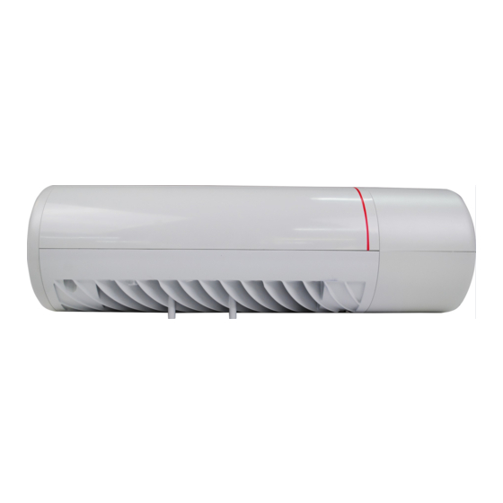
The ruggedized APs support wireless bridges, comply with IEEE 802.11a/b/g/n/ac/ac Wave 2, and can provide services simultaneously on the 2.4 GHz and 5 GHz frequency bands to support more access users. The AP8082DN and AP8182DN meet outdoor network deployment requirements with the following advantages:... - Page 9 AP8082DN and AP8182DN Hardware Installation and Maintenance Guide 1 Product Overview Figure 1-1 Appearance of the AP8082DN Figure 1-2 Appearance of the AP8182DN Table 1-1 describes interfaces on the AP8082DN and AP8182DN. Issue 03 (2019-04-01) Copyright © Huawei Technologies Co., Ltd.
-
Page 10: Indicator Description
1.2 Indicator Description The AP8082DN and AP8182DN provide multiple indicators: SYS indicator, LINK/ACT indicator, WIRELESS indicator, and DUAL-BAND PORT indicator. The following tables describe indicators on the AP8082DN and AP8182DN. - Page 11 AP8082DN and AP8182DN Hardware Installation and Maintenance Guide 1 Product Overview NOTE l The AP8082DN does not provide the dual-band port indicator. l Indicator colors may vary slightly at different temperature. SYS Indicator Table 1-2 Descriptions about the SYS indicator...
- Page 12 Blinking The Ethernet connection fails, and the PoE OUT function is faulty. The AP Green Steady on The Ethernet connection is normal, and no data is does not being transmitted. provide Issue 03 (2019-04-01) Copyright © Huawei Technologies Co., Ltd.
- Page 13 The AP is not transmitting or receiving data or the signal strength is extremely low. Blinking once every The AP is transmitting or receiving data 2s (0.5 Hz) normally, and the signal strength is low. Issue 03 (2019-04-01) Copyright © Huawei Technologies Co., Ltd.
-
Page 14: Basic Specifications
The dual-band port function is disabled, and the port is working on a single band. 1.3 Basic Specifications Table 1-7 provides basic specifications of the AP8082DN and AP8182DN. Issue 03 (2019-04-01) Copyright © Huawei Technologies Co., Ltd. -
Page 15: Ordering Information
Up to 149 MPH Atmospheric 53 kPa to 106 kPa pressure 1.4 Ordering Information To place an order, contact technical support personnel. Part Number Description 02351KQB AP8082DN Mainframe(11ac Wave2,Outdoor,4X4 Dual-Band,Built-in Antenna) Issue 03 (2019-04-01) Copyright © Huawei Technologies Co., Ltd. - Page 16 AP8082DN and AP8182DN Hardware Installation and Maintenance Guide 1 Product Overview Part Number Description 02351KQC AP8182DN Mainframe(11ac Wave2,Outdoor,4X4 Dual-Band,External Antenna) Issue 03 (2019-04-01) Copyright © Huawei Technologies Co., Ltd.
-
Page 17: Ap Installation
Place the device in a dry and flat position away from any liquid and prevent the device from slipping. Keep the device clean. Do not put the device and tools in the aisles. Issue 03 (2019-04-01) Copyright © Huawei Technologies Co., Ltd. - Page 18 Table 2-1 Tools Phillips screwdriver ESD gloves Slip-proof glove Marker Hammer drill Claw hammer Diagonal pliers Wire stripper RJ45 crimping tool Cable cutter Network cable tester Multimeter Ladder Utility knife Level Issue 03 (2019-04-01) Copyright © Huawei Technologies Co., Ltd.
-
Page 19: Installation Flowchart
Scissors Inner hexagon wrench (The Optical power meter wrench is 200 mm long or longer, M4 and M6) 2.2 Installation Flowchart The following figure shows the process for installing an AP. Issue 03 (2019-04-01) Copyright © Huawei Technologies Co., Ltd. -
Page 20: Unpacking The Equipment
Usually, the packing list contains the following items. AP device Mounting bracket PG connector Expansion bolt Hose clamp OT terminal Quick start guide Warranty card MAC address label SN label Issue 03 (2019-04-01) Copyright © Huawei Technologies Co., Ltd. -
Page 21: Determining The Installation Position
The recommended installation space is the same for the AP8082DN and AP8182DN. The following uses the default configuration of the AP8182DN as an example to describe... - Page 22 Dimensions (unit: mm) gurati Mode Directl connec ted to omnidi rection antenn withou t an enclos Directl connec ted to omnidi rection antenn with enclos Config ured with remote antenn with enclos Issue 03 (2019-04-01) Copyright © Huawei Technologies Co., Ltd.
- Page 23 If antennas are mounted to the same pole facing the same direction, the vertical distance between them should be at least 5 m. l The antennas should be placed at least 2 km away from the 4G signal tower of the carrier. Issue 03 (2019-04-01) Copyright © Huawei Technologies Co., Ltd.
-
Page 24: Installing The Ap
When the tightening torx of a screw reaches 12 N•m, the screw still properly works, without crack or damage on the wall. Mounting kits and expansion bolts are required to install the AP on a wall. Installing an AP8082DN Installing an AP8182DN Issue 03 (2019-04-01) Copyright © Huawei Technologies Co., Ltd. - Page 25 The length of the M6 inner hexagon screwdrivers must be greater than or equal to 200 mm. l The adjustment range of the angle-adjustable mounting bracket for the AP8082DN is as follows: Without an enclosure: The adjustment range of the vertical angle is ±30°, and that of the horizontal angle is ±40°.
- Page 26 Remove the topmost screw from the wall-side mounting bracket, hang the AP-side mounting bracket onto the topmost screw, and tighten the screw until the screw passes through the hole of the horizontal scale plate (the screw should not be too tight). Issue 03 (2019-04-01) Copyright © Huawei Technologies Co., Ltd.
- Page 27 Use an 8 mm drill bit to drill 35mm to 40 mm deep holes in the drilling positions and hammer the expansion bolts into the installation holes until the flat washers are completely attached to the wall. Then, remove the nut, spring washer, and flat washer in order. Issue 03 (2019-04-01) Copyright © Huawei Technologies Co., Ltd.
- Page 28 Hang the wall-side mounting bracket on the expansion bolts and use a wrench to fasten the flat washers, spring washers, and nuts in order. 5 N•m Use four M4x14 hexagon socket head cap screws to fasten the AP-side mounting bracket to the AP. Issue 03 (2019-04-01) Copyright © Huawei Technologies Co., Ltd.
-
Page 29: Installing The Device On A Pole
An outdoor AP must be installed on a pole with a diameter of 48 mm to 114 mm and the difference between the outer and inner diameters should be at least 2.5 mm. Installing an AP8082DN Installing an AP8182DN Issue 03 (2019-04-01) Copyright © Huawei Technologies Co., Ltd. - Page 30 The length of the M6 inner hexagon screwdrivers must be greater than or equal to 200 mm. l The adjustment range of the angle-adjustable mounting bracket for the AP8082DN is as follows: Without an enclosure: The adjustment range of the vertical angle is ±30°, and that of the horizontal angle is ±40°.
- Page 31 Use an M6 inner hex torque screwdriver to loosen the screw on the hose clamp to open it. Lead the hose clamp through the mounting bracket and secure the mounting bracket to the pole. Issue 03 (2019-04-01) Copyright © Huawei Technologies Co., Ltd.
- Page 32 The AP is of the cyclinder shape. It is recommended that this step be performed in the package. Hang the AP with the AP-side mounting bracket to the wall-side mounting bracket and tighten the screws to secure the AP. Issue 03 (2019-04-01) Copyright © Huawei Technologies Co., Ltd.
-
Page 33: Installing An Enclosure For An Ap
Table 2-4 Mappings between enclosures and AP models Applicable Enclosure Matching Enclosure Type Model Scenario AP8082D With an 1. Top enclosure (part enclosure number: 21203905) 2. Cabling enclosure (part number: 21203906) 3. Whip antenna enclosure (part number: 21203907) Issue 03 (2019-04-01) Copyright © Huawei Technologies Co., Ltd. - Page 34 Configured with remote antennas, with an enclosure Installing an Enclosure To install enclosures (21203905 and 21203907) for an AP: Clasp two hooks on the enclosure into notches on the device end. Issue 03 (2019-04-01) Copyright © Huawei Technologies Co., Ltd.
- Page 35 Uninstalling an Enclosure Use a flat-head screwdriver to pry open the enclosure from the gap on the front of the Issue 03 (2019-04-01) Copyright © Huawei Technologies Co., Ltd.
-
Page 36: Connecting Cables
If the enclosure is still on the AP, use the flat-head screwdriver to pry the spring outward from the notch on the rear of the AP and then remove the enclosure. 2.6 Connecting Cables Issue 03 (2019-04-01) Copyright © Huawei Technologies Co., Ltd. -
Page 37: Connecting Rf Cables
RF cable deployment requirements It is recommended that you connect a 50 ohm RF load to an idle antenna interface and wrap the RF load with insulation tape and waterproof tape. Huawei offers 50 ohm RF loads for you to purchase. - Page 38 Wrap each layer of tape tightly. Bundle cable ties at both ends of the tape. PVC insulation tape Waterproof adhesive tape Issue 03 (2019-04-01) Copyright © Huawei Technologies Co., Ltd.
-
Page 39: Connecting Optical Fibers And Network Cables
(4) External connector shell Select an optical cable of a proper length based on onsite cabling. Remove the waterproof block from the rubber ring of the connector, as shown in the following figure. Issue 03 (2019-04-01) Copyright © Huawei Technologies Co., Ltd. - Page 40 Turn the support to find the correct optical fiber installation slot and push the support forward (together with the rubber ring) until the optical fiber is installed Issue 03 (2019-04-01) Copyright © Huawei Technologies Co., Ltd.
- Page 41 Put the network cable through waterproof PG connectors. Connect the RJ45 connector to the Ethernet interface on the AP and secure the waterproof PG connector. See figures b, c, and d. Issue 03 (2019-04-01) Copyright © Huawei Technologies Co., Ltd.
-
Page 42: Connecting Ground Cables
Outdoor APs support built-in surge protection on all interfaces, but the surge protection works only when the outdoor APs are grounded. Requirements for laying out ground cables The ground cables must be connected to a group of ground bars. Issue 03 (2019-04-01) Copyright © Huawei Technologies Co., Ltd. - Page 43 5 ohms on a multimeter. The grounding resistance in an area with a high earth resistance rate should be less than 10 ohms. 1.4 N•m Connecting the ground bar 4.8 N•m Issue 03 (2019-04-01) Copyright © Huawei Technologies Co., Ltd.
-
Page 44: Installing Outdoor Antennas
Install the antenna pole on a parapet or concrete bed on the roof of the building. Use a 40 mm x 4 mm flat steel to connect the antenna pole to an earth mat. Secure the directional outdoor antenna on the pole with an antenna support. Issue 03 (2019-04-01) Copyright © Huawei Technologies Co., Ltd. - Page 45 Parapet height > 1.2 m Parapet height < 1.2 m Figure 2-10 shows outdoor AP installation scenarios. The distance between 5 GHz antenna and 2.4 GHz antenna should be more than 0.5 m. Issue 03 (2019-04-01) Copyright © Huawei Technologies Co., Ltd.
- Page 46 The distance between two omnidirectional antennas should be more than 0.5 m. Figure 2-11 shows installation of an omnidirectional outdoor antenna. Issue 03 (2019-04-01) Copyright © Huawei Technologies Co., Ltd.
- Page 47 AP. Tighten an antenna to an AP with a tightening torque of 0.8 Nm. Figure 2-12 Installing omnidirectional outdoor antennas on an AP Issue 03 (2019-04-01) Copyright © Huawei Technologies Co., Ltd.
-
Page 48: Connecting The Security Lock
Terminals of the power cables and PGND cables are welded or cramped firmly. All power cables or PGND cables are not short-circuited or reversely connected and must be intact with no damage. Issue 03 (2019-04-01) Copyright © Huawei Technologies Co., Ltd. -
Page 49: Powering On The Ap
After the AP is powered on, observe indicators on the AP to determine the system running status. For details, see 1.2 Indicator Description. NOTE Do not frequently power on and off the device. Issue 03 (2019-04-01) Copyright © Huawei Technologies Co., Ltd. -
Page 50: Logging In To The Ap
AP8082DN and AP8182DN Hardware Installation and Maintenance Guide 3 Logging In to the AP Logging In to the AP For details about how to log in to the AP, see 6.10 AP Login. Issue 03 (2019-04-01) Copyright © Huawei Technologies Co., Ltd. -
Page 51: Hardware Failures
Check whether the power output mode of the power sourcing equipment is supported by the powered device. Check whether the peer switch is grounded. If not, ground it properly. Check whether the power sourcing equipment can support the maximum power consumption of the device. Issue 03 (2019-04-01) Copyright © Huawei Technologies Co., Ltd. -
Page 52: An Optical Interface Cannot Turn Up
Check whether the network cable or distribution frame is faulty. If the device still cannot be powered on, the device itself is faulty. Contact technical support personnel or Huawei agent and ask them to replace the device. NOTE The output power of an 802.3af PSE port is 15.4 W, that of an 802.3at PSE port is 30 W, and that of an 802.3bt PSE port is 60 W. -
Page 53: Maintaining The Device
Never look directly into an optical module or the ends of optical fibers. Optical modules and connected fibers emit laser radiation that will cause eye damage. l Use optical modules certified for Huawei. Using other optical modules may affect service stability and Huawei can accept no liability for the outcome. - Page 54 Figure 5-3 shows the locking clip on an SC/PC connector. The locking clip is – released automatically when you pull the SC/PC connector. Figure 5-1 LC/PC connector Figure 5-2 MPO connector Issue 03 (2019-04-01) Copyright © Huawei Technologies Co., Ltd.
- Page 55 Identify the optical fibers to be connected to the optical module. Remove the dust caps from the optical fibers and insert the optical fibers to the bores of the optical module. Issue 03 (2019-04-01) Copyright © Huawei Technologies Co., Ltd.
- Page 56 Follow-up Procedure If the new optical module does not work, contact the equipment supplier or local maintenance personnel for technical support. Issue 03 (2019-04-01) Copyright © Huawei Technologies Co., Ltd.
-
Page 57: Appendix
If the cable jacket or insulation is visibly dirty, clean it before assembly. If the jacket or insulation of a cable has visible damage, irreparable scuffing, or other defects, do not use the cable. Issue 03 (2019-04-01) Copyright © Huawei Technologies Co., Ltd. -
Page 58: Assembling Power Cables
Precautions for Assembly Use dedicated tools or tools delivered by Huawei and follow the methods given here during assembly. Hold terminals of cables instead of pulling the cables themselves when installing or removing cable components. - Page 59 Step 1 Bind a cable tie, separate the socket and nut, and install them on the cable, as shown in Figure 6-2. Figure 6-2 Installing the nut on the cable Step 2 Strip the cable as shown in Figure 6-3. Issue 03 (2019-04-01) Copyright © Huawei Technologies Co., Ltd.
- Page 60 Step 4 Use a Phillips screwdriver to tighten the crimping screw in "+" hole, rotate the connector by 180 degree, and tighten the crimping screw in "-" hole, as shown in Figure 6-5. Issue 03 (2019-04-01) Copyright © Huawei Technologies Co., Ltd.
- Page 61 Figure 6-7 Tightening the socket Step 7 Pre-tighten the socket and nut and use the Phillips screwdriver to tighten the nut with the tightening torque no less than 1.2 N•m, as shown in Figure 6-8. Issue 03 (2019-04-01) Copyright © Huawei Technologies Co., Ltd.
- Page 62 Step 9 If devices are installed outdoor, wrap three layers of PVC insulation tape around the connector for protection, as shown in Figure 6-10. Ensure that proper quantity of the PVC insulation tape is used for wrapping the connector, facilitating the connector uninstallation in later maintenance. Issue 03 (2019-04-01) Copyright © Huawei Technologies Co., Ltd.
-
Page 63: Assembling A Dc 2-Pin Round Connector (B)
The color and appearance of cables in this topic are for reference only. The cable color and appearance vary depending on countries and regions. Figure 6-11 shows components of the DC round waterproof connector. Issue 03 (2019-04-01) Copyright © Huawei Technologies Co., Ltd. - Page 64 , and 2 x 6 mm Power cables supported by clamping jaw 2: 2 x 8 AWG and 2 x 10 mm Figure 6-12 Replacing clamping jaws 1. Clamping jaw 1 2. Clamping jaw 2 Issue 03 (2019-04-01) Copyright © Huawei Technologies Co., Ltd.
- Page 65 The stripping ruler card is delivered with the components of the connector. Cut the padding using diagonal pliers. Gently strip the insulation sheath to avoid damage to the conductor metal. Ensure that the edge of core wires is not split. Issue 03 (2019-04-01) Copyright © Huawei Technologies Co., Ltd.
- Page 66 Step 6 Twist the shield layers into one strand and insert it into the shield slot, tighten the tail screw, and fasten the shielded layer with tightening torque 1.4 N•m, as shown in Figure 6-17. Issue 03 (2019-04-01) Copyright © Huawei Technologies Co., Ltd.
- Page 67 Figure 6-18 Tightening the socket and enclosure Step 8 Pre-tighten the nut and socket and further tighten the nut using a torque wrench (opening width: 28 mm), as shown in Figure 6-19. Issue 03 (2019-04-01) Copyright © Huawei Technologies Co., Ltd.
- Page 68 Ensure that the short circuit does not occur between the metal enclosure and connector's positive and negative holes. Step 10 If devices are installed outdoor, wrap three layers of PVC insulation tape around the connector for protection, as shown in Figure 6-21. Issue 03 (2019-04-01) Copyright © Huawei Technologies Co., Ltd.
-
Page 69: Assembling The Ot Terminal And Power Cable
Ensure that proper quantity of the PVC insulation tape is used for wrapping the connector, facilitating the connector uninstallation in later maintenance. ----End 6.1.2.3 Assembling the OT Terminal and Power Cable Context Figure 6-22 shows the components of an OT terminal and a power cable. Issue 03 (2019-04-01) Copyright © Huawei Technologies Co., Ltd. - Page 70 When you strip a power cable, do not damage the conductor of the cable. l If the bare crimping terminal is not provided by Huawei, the value of L1 is 1 mm (0.04 in.) to 2 mm (0.08 in.) greater than the value of L.
- Page 71 After the conductor is fed into the OT terminal, the protruding part of the conductor, or L2 in Figure 6-24, must not be longer than 2 mm (0.08 in.). Step 4 Crimp the joint parts of the bare crimping terminal and the conductor, as shown in Figure 6-25. Issue 03 (2019-04-01) Copyright © Huawei Technologies Co., Ltd.
-
Page 72: Assembling The Jg Terminal And Power Cable
Stop heating the shrink tubing when the connector is securely locked in the shrink tubing. Do not heat the shrink tubing too long as this may damage the insulation coating. ----End 6.1.2.4 Assembling the JG Terminal and Power Cable Issue 03 (2019-04-01) Copyright © Huawei Technologies Co., Ltd. - Page 73 6-3. l When you strip a power cable, do not damage the conductor of the cable. l If the bare crimping terminal is not provided by Huawei, you can adjust the value of L as required. Figure 6-28 Stripping a power cable (JG terminal) Issue 03 (2019-04-01) Copyright ©...
- Page 74 Step 4 Crimp the joint parts of the bare crimping terminal and the conductor, as shown in Figure 6-30. Figure 6-30 Crimping the joint parts of the bare crimping terminal and the conductor (JG terminal) Issue 03 (2019-04-01) Copyright © Huawei Technologies Co., Ltd.
-
Page 75: Assembling The Cord End Terminal And The Power Cable
Step 1 Strip a part of the insulation to expose the cable conductor with a length of L1, as shown in Figure 6-33. The recommended values of L1 are listed in Table 6-4. Issue 03 (2019-04-01) Copyright © Huawei Technologies Co., Ltd. - Page 76 Figure 6-34. After the conductor is fed into the cord end terminal, the protruding part of the conductor must not be longer than 1 mm (0.04 in.). Issue 03 (2019-04-01) Copyright © Huawei Technologies Co., Ltd.
- Page 77 Terminal (mm (in. 0.25 (0.0004) 1 (0.04) 0.5 (0.0008) 1 (0.04) 1.0 (0.0015) 1.5 (0.06) 1.5 (0.0023) 1.5 (0.06) 2.5 (0.0039) 2.4 (0.09) 4 (0.006) 3.1 (0.12) 6 (0.009) 4 (0.16) Issue 03 (2019-04-01) Copyright © Huawei Technologies Co., Ltd.
-
Page 78: Assembling Ethernet Cables
E. Jacket of Ethernet cable F. Shield layer of Ethernet G. Twisted-pair wires cable Procedure Step 1 Fit the jacket of the connector onto the Ethernet cable, as shown in Figure 6-37. Issue 03 (2019-04-01) Copyright © Huawei Technologies Co., Ltd. - Page 79 Figure 6-38 Removing the jacket of a twisted-pair cable (unit: mm (in.)) Step 3 Fit the metal shell onto the twisted-pair cable. The shield layer is covered by the metal shell, as shown in Figure 6-39. Issue 03 (2019-04-01) Copyright © Huawei Technologies Co., Ltd.
- Page 80 Step 5 Lead the four pairs of twisted-pair wires through the wire holder, as shown in Figure 6-41 Figure 6-42. Ensure that the colored wires are in the correct location in the cable. Figure 6-41 Leading wires through the wire holder Issue 03 (2019-04-01) Copyright © Huawei Technologies Co., Ltd.
- Page 81 6-6. Figure 6-43 Four pairs of cables on a wire holder Figure 6-44 Connections between wires and pins White-Orange Orange White-Green Blue White-Blue Green White -Brown Brown Pin 8 Pin 1 Issue 03 (2019-04-01) Copyright © Huawei Technologies Co., Ltd.
- Page 82 Step 8 Put the connector body onto the wire holder and turn the metal shell by 90°, as shown in Figure 6-46. NOTE Ensure that the wire holder is in good contact with the connector body. Issue 03 (2019-04-01) Copyright © Huawei Technologies Co., Ltd.
- Page 83 Step 10 Push the jacket towards the metal shell until the metal shell is covered. This completes the assembly of one end of the cable, as shown in Figure 6-48. Figure 6-48 Pushing the metal shell Issue 03 (2019-04-01) Copyright © Huawei Technologies Co., Ltd.
-
Page 84: Assembling An Optimized Shielded Rj45 Connector And Sftp Network Cables
Step 1 Strip 20 mm outer jacket off the network cable, peel off the braid shield backward, and cut off the aluminum foil and protection band, as shown in Figure 6-50. Issue 03 (2019-04-01) Copyright © Huawei Technologies Co., Ltd. - Page 85 Step 3 Hold the arranged core wires and route them through the load bar, as shown in Figure 6-52. Table 6-7 shows the mapping between the core wires and pins of the connector. Issue 03 (2019-04-01) Copyright © Huawei Technologies Co., Ltd.
- Page 86 Step 4 After routing core wires through the load bar, move the load bar to the bottom to connect to the cable support rack, and neatly cut the edge cables, as shown in Figure 6-53. Issue 03 (2019-04-01) Copyright © Huawei Technologies Co., Ltd.
- Page 87 Step 6 Use the crimping tool to crimp the connector, as shown in Figure 6-55. Use cutting pliers to neatly cut braid shields exposed out of the connector along the load bar, as shown in Figure 6-56. Figure 6-55 Crimping the connector Issue 03 (2019-04-01) Copyright © Huawei Technologies Co., Ltd.
-
Page 88: Assembling An Integrated Shielded Rj45 Connector And Sftp Network Cables
This topic describes how to assemble an integrated shielded RJ45 connector with a Secure File Transfer Protocol (SFTP) straight-through network cable as an example. The connector does not have a cable support rack or metal jacket. Figure 6-57 shows the integrated shielded RJ45 connector. Issue 03 (2019-04-01) Copyright © Huawei Technologies Co., Ltd. - Page 89 6-58. Ensure that the shielded layer is intact when stripping outer jackets off the network cable. Keep the cable insulation intact when stripping the shielded layer. Figure 6-58 Stripping the cable Issue 03 (2019-04-01) Copyright © Huawei Technologies Co., Ltd.
- Page 90 Table 6-8 Mapping between core wires and pins Pin ID Core Wire Color White-orange Orange White-green Blue White-blue Green White-brown Brown Step 3 Route the arranged core wires through the RJ45 connector, as shown in Figure 6-60. Issue 03 (2019-04-01) Copyright © Huawei Technologies Co., Ltd.
- Page 91 6-62. Figure 6-62 Neatly cutting braid shields Step 6 Repeat Step 1 through Step 5 to assemble the integrated shielded RJ45 connector on the other end of the network cable. ----End Issue 03 (2019-04-01) Copyright © Huawei Technologies Co., Ltd.
-
Page 92: Assembling A Shielded Rj45 Connector And An Ftp Network Cable
D: Aluminum foil used as the E: Network cable jacket twisted pair network cable shield jacket Procedure Step 1 Route the network cable through the connector jacket, as shown in Figure 6-66. Issue 03 (2019-04-01) Copyright © Huawei Technologies Co., Ltd. - Page 93 Figure 6-67 Stripping the outer jacket Step 3 Pull outward the shielded aluminum foil and cut off the PET membrane and ground cables along the end face of the outer jacket, as shown in Figure 6-68. Issue 03 (2019-04-01) Copyright © Huawei Technologies Co., Ltd.
- Page 94 Figure 6-70. Figure 6-71 shows pin arrangement of each contact of the connector. Figure 6-69 Mapping between colors and pins Issue 03 (2019-04-01) Copyright © Huawei Technologies Co., Ltd.
- Page 95 Step 5 Insert the arranged four twisted pair cables into the connector, as shown in Figure 6-72. Cables must be inserted into the bottom. The aluminum foil must keep intact after cables are inserted into the connector. Figure 6-72 Inserting cables into the connector Issue 03 (2019-04-01) Copyright © Huawei Technologies Co., Ltd.
- Page 96 Figure 6-73. Figure 6-73 Crimping the connector Step 7 Move the connector jacket to the connector body to wrap the connector shell, as shown in Figure 6-74. Issue 03 (2019-04-01) Copyright © Huawei Technologies Co., Ltd.
-
Page 97: Assembling An Unshielded Rj45 Connector And Ethernet Cable
Figure 6-75 shows the components of an unshielded RJ45 connector and cable. Figure 6-75 Components of an unshielded RJ45 connector and cable A. Plug of connector B. Jacket C. Twisted-pair wires Issue 03 (2019-04-01) Copyright © Huawei Technologies Co., Ltd. - Page 98 Pin 8 Brown Pin 1 Table 6-9 Connections between wires and pins (using a straight-through cable as an example) Matching Pins of Wires Wire Color White-Orange Orange White-Green Blue White-Blue Green White-Brown Issue 03 (2019-04-01) Copyright © Huawei Technologies Co., Ltd.
-
Page 99: Checking The Appearance Of Contact Strips
The height should be 6.02 ± 0.13 mm (0.237 ± 0.005). If a measuring tool is not available, you can compare the connector with a standard connector. Figure 6-79 shows an unqualified piece, and Figure 6-80 shows a qualified piece. Issue 03 (2019-04-01) Copyright © Huawei Technologies Co., Ltd. - Page 100 Step 2 Hold an RJ45 connector and turn it 45°. Observe the top edges of the metal contact strips. Figure 6-81 shows an unqualified piece. Figure 6-81 Unparallel contact strips of different heights Issue 03 (2019-04-01) Copyright © Huawei Technologies Co., Ltd.
- Page 101 RJ45, and that the contact strip blade extends beyond the ends of the wires and is crimped with the wires. If not, replace the connector. Figure 6-84 shows an unqualified piece. Figure 6-84 Wires not in good contact with the edge of the RJ45 Issue 03 (2019-04-01) Copyright © Huawei Technologies Co., Ltd.
-
Page 102: Testing The Connection Of Assembled Cables
6.1.3.7 Testing the Connection of Assembled Cables Context Huawei provides two types of Ethernet cables: straight-through cables and crossover cables. Straight-through cables are connected in a one-to-one manner. They are used to connect terminals such as a computer or switch to network devices. - Page 103 Step 3 Gently shake the connector and repeat Step 2 to check whether the metal contact strips are in good contact with the core wires and Ethernet ports, as shown in Figure 6-87. Issue 03 (2019-04-01) Copyright © Huawei Technologies Co., Ltd.
- Page 104 NOTE If a tester is not available, you can use a multimeter to perform a simple test, as shown in Figure 6-88. Figure 6-88 Testing the connection of an Ethernet cable Issue 03 (2019-04-01) Copyright © Huawei Technologies Co., Ltd.
-
Page 105: Common Network Cable Faults And Preventive Measures
If indicators 1 to G turn on in a wrong sequence, remake the network cable. Issue 03 (2019-04-01) Copyright © Huawei Technologies Co., Ltd. -
Page 106: Assembling Feeders
N coaxial connector and a 1/2" feeder cable. Figure 6-89 Components of an N coaxial connector and a 1/2" feeder cable A. Body of connector B. Back shell of connector C. O-ring seal D. Heat-shrink tubing Issue 03 (2019-04-01) Copyright © Huawei Technologies Co., Ltd. - Page 107 Step 2 Use a brush to remove the dirt on the cross-section of the feeder cable. Step 3 Feed the feeder cable into the heat-shrink tubing, and cover the outer conductor of the feeder cable with the O-ring seal, as shown in Figure 6-91. Issue 03 (2019-04-01) Copyright © Huawei Technologies Co., Ltd.
- Page 108 Step 5 Mount the body of the connector onto the feeder cable so that the inner conductors of the connector and feeder cable are connected. Use a spanner (27 N•m to 30 N•m torque recommended) to fasten the body and back shell, as shown in Figure 6-93. Issue 03 (2019-04-01) Copyright © Huawei Technologies Co., Ltd.
- Page 109 Step 6 Push the heat-shrink tubing towards the connector, as shown in Figure 6-94. Then, heat the tube. Figure 6-94 Assembled N connector Step 7 After the components are assembled, install the connector, as shown in Figure 6-95. Issue 03 (2019-04-01) Copyright © Huawei Technologies Co., Ltd.
-
Page 110: Assembling A Straight Male Coaxial N Connector And An Rg8U Feeder
If they are conductive, re-assemble the radio cable. 6.1.4.2 Assembling a Straight Male Coaxial N Connector and an RG8U Feeder Context Figure 6-96 shows the coaxial N connector and RG8U feeder. Issue 03 (2019-04-01) Copyright © Huawei Technologies Co., Ltd. - Page 111 I: Internal conductor of the feeder Procedure Step 1 Strip the feeder with the length shown in Figure 6-97. Ensure that the shielded layer F is intact after the stripping. Issue 03 (2019-04-01) Copyright © Huawei Technologies Co., Ltd.
- Page 112 Figure 6-99 Installing the clip Step 4 Peel off the shielded layer (F) to the direction of the clip (C) so that the aluminum foil (G) is exposed, as shown in Figure 6-100. Issue 03 (2019-04-01) Copyright © Huawei Technologies Co., Ltd.
- Page 113 Figure 6-102 Cutting off the aluminum foil and insulation medium of the feeder Step 7 Use the file to taper the internal conductor (I) of the feeder, as shown in Figure 6-103. Issue 03 (2019-04-01) Copyright © Huawei Technologies Co., Ltd.
- Page 114 Step 9 Insert the half-finished part into the main body of the connector (A) and rotate the nut (D) and the connector's main body until you cannot rotate further, as shown in Figure 6-105. Issue 03 (2019-04-01) Copyright © Huawei Technologies Co., Ltd.
- Page 115 Figure 6-106 Fixing the nut to the connector shell body Step 11 Figure 6-107 shows the effect drawing after the assembling is complete. Figure 6-107 Effect drawing of the straight male coaxial N connector Issue 03 (2019-04-01) Copyright © Huawei Technologies Co., Ltd.
-
Page 116: Installing Cable Accessories
For example, in this document, the adapters of cable connectors have separate interfaces. In the actual situation, the adapters may have interfaces fixed on equipment. Tools Use dedicated tools provided or specified by Huawei and follow the installation procedure described here. Bending Radius... -
Page 117: Installing Power Adapters
Figure 6-108 Aligning the OT terminal with a connecting hole NOTE When you install an OT terminal, the crimping sleeve is installed as shown in Figure 6-109, where A is correct and B is incorrect. Issue 03 (2019-04-01) Copyright © Huawei Technologies Co., Ltd. - Page 118 Ensure that the OT terminal is not in contact with other terminals or metal components. Move the cable slightly and ensure that it is securely connected, as shown in Figure 6-111. Issue 03 (2019-04-01) Copyright © Huawei Technologies Co., Ltd.
- Page 119 – Bend the upper OT terminal at a 45- or 90-degree angle, as shown in Figure 6-112. – Cross the two terminals, as shown in Figure 6-113. Figure 6-112 Bending the upper OT terminal at a 45- or 90-degree angle Figure 6-113 Crossing two terminals Issue 03 (2019-04-01) Copyright © Huawei Technologies Co., Ltd.
-
Page 120: Installing The Cord End Terminal
Step 2 Insert the terminal into the jack vertically, and turn the screw clockwise to fasten the terminal, as shown in Figure 6-115. Figure 6-115 Feeding the terminal into the jack Issue 03 (2019-04-01) Copyright © Huawei Technologies Co., Ltd. -
Page 121: Installing A 2-Pin Round Connector And A Dc Power Cable
Wrap a layer of PVC tape from the bottom top, with the later covering one third of the previous one, as shown in Figure 6-117. Figure 6-117 Wrapping the PVC tape Issue 03 (2019-04-01) Copyright © Huawei Technologies Co., Ltd. - Page 122 Figure 6-120. After wrapping each layer of the tape, use your hands to tightly press the tape. Figure 6-120 Wrapping three layers of the PVC tape Issue 03 (2019-04-01) Copyright © Huawei Technologies Co., Ltd.
- Page 123 Step 2 Fix the DC power cable connector to the PWR port, as shown in Figure 6-121. Ensure that positive and negative polarities are correct during the installation. Figure 6-121 Installing the round connector Issue 03 (2019-04-01) Copyright © Huawei Technologies Co., Ltd.
-
Page 124: Installing Ethernet Adapters
Figure 6-122 Holding the male and female shielded connectors Step 2 Insert the male connector into the female connector, as shown in Figure 6-123. Figure 6-123 Feeding the male shielded connector into the female shielded connector Issue 03 (2019-04-01) Copyright © Huawei Technologies Co., Ltd. -
Page 125: Installing An Unshielded Ethernet Connector
Figure 6-125 Removing a shielded Ethernet connector ----End 6.1.5.3.2 Installing an Unshielded Ethernet Connector Procedure Step 1 Hold the male and female connectors, with the male connector facing the female connector, as shown in Figure 6-126. Issue 03 (2019-04-01) Copyright © Huawei Technologies Co., Ltd. - Page 126 Step 3 A crisp click indicates that the connector is locked by the locking key. Pull the connector slightly and ensure that it is securely connected. Figure 6-128 shows an installed Ethernet connector. Figure 6-128 Installed unshielded Ethernet connector Issue 03 (2019-04-01) Copyright © Huawei Technologies Co., Ltd.
-
Page 127: Installing Fiber Connectors
Step 2 Clean the pins again by using dust-free cotton. If necessary, clean the pins by using an air gun. Ensure that the pins are free from any fiber or debris. ----End 6.1.5.4.2 Installing an FC Fiber Connector Issue 03 (2019-04-01) Copyright © Huawei Technologies Co., Ltd. - Page 128 Figure 6-131. Figure 6-131 Feeding the male connector into the female connector Step 4 Fasten the locking nut clockwise and ensure that the connector is securely installed, as shown Figure 6-132. Issue 03 (2019-04-01) Copyright © Huawei Technologies Co., Ltd.
-
Page 129: Installing An Lc Fiber Connector
Step 1 Remove the dustproof cap of the LC fiber connector and store it for future use. Step 2 Align the core pin of the male connector with that of the female connector, as shown in Figure 6-134. Issue 03 (2019-04-01) Copyright © Huawei Technologies Co., Ltd. - Page 130 Figure 6-135 Feeding the male connector into the female connector Step 4 A clicking sound indicates that the male connector is locked, as shown in Figure 6-136. Figure 6-136 Installed LC connector Issue 03 (2019-04-01) Copyright © Huawei Technologies Co., Ltd.
-
Page 131: Installing The Sc Fiber Connector
(not the pigtail). When you hear a click, the fiber connector is secured by the clips (internal parts, not illustrated in the figure). Pull the fiber connector gently. If the connector does not loosen, the installation is complete. See Figure 6-139. Issue 03 (2019-04-01) Copyright © Huawei Technologies Co., Ltd. -
Page 132: Installing An Mpo Connector
Step 1 Remove the dustproof cap of the MPO fiber connector and store it for future use. Step 2 Align the core pin of the male connector with that of the female connector, as shown in Figure 6-141. Issue 03 (2019-04-01) Copyright © Huawei Technologies Co., Ltd. - Page 133 Figure 6-142. Figure 6-142 Installed MPO fiber connector Step 4 To disassemble an MPO fiber connector, hold the shell labeled "PULL" and remove the male connector, as shown in Figure 6-143. Issue 03 (2019-04-01) Copyright © Huawei Technologies Co., Ltd.
-
Page 134: Replacing The Mold Of The Crimping Tool
Figure 6-144 Loosening two fastening screws Step 2 Hold the handles of the COAX crimping tools to open the self-locking mechanism. The jaw of the COAX crimping tools opens automatically, as shown in Figure 6-145. Issue 03 (2019-04-01) Copyright © Huawei Technologies Co., Ltd. - Page 135 Figure 6-146 Removing the mold from the COAX crimping tools Step 4 Place the mold to be installed into the jaw of the COAX crimping tools and align the screw holes, as shown in Figure 6-147. Issue 03 (2019-04-01) Copyright © Huawei Technologies Co., Ltd.
- Page 136 Step 6 Hold the handles of the COAX crimping tools with one hand. Tighten the two fastening screws clockwise. Figure 6-149 Figure 6-150shows the mold installed in the COAX crimping tool. Issue 03 (2019-04-01) Copyright © Huawei Technologies Co., Ltd.
-
Page 137: Environmental Requirements For Device Operation
The equipment room should also follow local regulations concerning the industrial construction, environmental protection, fire safety, and civil air defense. Construction must conform to government standards, regulations, and other requirements. Issue 03 (2019-04-01) Copyright © Huawei Technologies Co., Ltd. -
Page 138: Equipment Room Layout
An equipment room usually contains mobile switching equipment, telecommunications equipment, power supply equipment, and other auxiliary equipment. To ensure easy maintenance and management, place the equipment in different rooms. Figure 6-151 shows the layout of the equipment room. Issue 03 (2019-04-01) Copyright © Huawei Technologies Co., Ltd. -
Page 139: Construction Requirements For The Equipment Room
You can connect them to ground using a one megohm current-limiting resistor and connection line. Load-bearing The floor must bear loads larger than 150 kg/m (0.21 bf/in. capacity Issue 03 (2019-04-01) Copyright © Huawei Technologies Co., Ltd. -
Page 140: Equipment Room Environment
6.2.1.4 Equipment Room Environment Dust on devices may cause electrostatic discharge and result in poor contact for connectors or metal connection points. This problem can shorten the life span of devices and cause faults. Issue 03 (2019-04-01) Copyright © Huawei Technologies Co., Ltd. -
Page 141: Requirements For Corrosive Gases
Table 6-17 Requirements for corrosive gas concentration Chemical active material Unit Concentration ≤0.30 mg/m ≤0.10 mg/m ≤0.50 mg/m ≤1.00 mg/m ≤0.10 mg/m ≤0.10 mg/m Issue 03 (2019-04-01) Copyright © Huawei Technologies Co., Ltd. -
Page 142: Requirements For Esd Prevention
Keep the equipment far away from high-power radio transmitters, radar units, and high- frequency and high-current equipment. Use electromagnetic shielding if necessary. 6.2.1.8 Requirements for Lightning Proof Grounding Table 6-18 lists the requirements for lightning proof grounding. Issue 03 (2019-04-01) Copyright © Huawei Technologies Co., Ltd. - Page 143 Do not install a fuse or switch on the ground cable. l All ground cables should be as short as possible, and arranged in a straight line. Issue 03 (2019-04-01) Copyright © Huawei Technologies Co., Ltd.
-
Page 144: Requirements For Power Supply
For power distribution capacity in the equipment room, both the working current and fault current of the devices should be considered. Ensure that independent AC power supplies Issue 03 (2019-04-01) Copyright © Huawei Technologies Co., Ltd. -
Page 145: Recommendations For Ac Power Supply
UPS can rely on concatenation or parallel connection. When an inverter or a UPS is used, the active inverter is determined by the maximum power and a backup inverter is required. Issue 03 (2019-04-01) Copyright © Huawei Technologies Co., Ltd. -
Page 146: Requirements For Dc Power Supply
Improve reliability of the AC power supply system to reduce the necessary capacity of storage batteries. For small offices, increase the capacity of storage batteries if it is difficult to enhance reliability of the AC power supply system. Issue 03 (2019-04-01) Copyright © Huawei Technologies Co., Ltd. -
Page 147: Equipment Grounding Specifications
The grounding resistance in an area where the earth resistance rate is high should be less than 10 ohms. 6.3.3 Grounding Specifications for Devices Table 6-22 lists the equipment grounding specifications. Issue 03 (2019-04-01) Copyright © Huawei Technologies Co., Ltd. -
Page 148: Grounding Specifications For Communications Power Supply
The protective ground for the power supply and that for communication equipment share the same grounding conductor. If the power supply and the equipment are in the same equipment room, use the same protective ground bar for them if possible. Issue 03 (2019-04-01) Copyright © Huawei Technologies Co., Ltd. -
Page 149: Grounding Specifications For Signal Cables
Table 6-25 shows the specifications for the ground cable. Table 6-25 Specifications for laying out ground cables Description The grounding wire should not run parallel to or twist around the signal cable. Issue 03 (2019-04-01) Copyright © Huawei Technologies Co., Ltd. -
Page 150: Engineering Labels For Cables
Thickness: 0.09 mm (0.004 in.) Color: chalk white Material: polyester (PET) Ambient temperature: -29°C (-20.2°F) to +149°C (300.2°F) Printed by a laser printer and written with a marker Pass UL and CSA authentication Issue 03 (2019-04-01) Copyright © Huawei Technologies Co., Ltd. -
Page 151: Type And Structure
The identification plate has an embossed area 0.2 mm x 0.6 mm (0.008 in. x 0.02 in.) around (symmetric on both sides), and the area in the middle is for affixing the label, as shown in Figure 6-154. Issue 03 (2019-04-01) Copyright © Huawei Technologies Co., Ltd. -
Page 152: Label Printing
Template for Printing You can obtain a template from the Huawei local office to print labels. The template is made in Microsoft Word. Follow these instructions to use the template: You can modify the contents of the template. Do not change settings of centered characters, direction, and fonts. - Page 153 Figure 6-155 Warning prompt before printing After the page setup has been made correctly, save it for future use. This page setup is only necessary the first time you use the template to print the labels. Issue 03 (2019-04-01) Copyright © Huawei Technologies Co., Ltd.
-
Page 154: Writing Labels
(Times New Roman). Table 6-26 Standard typeface for handwriting Determine the size of characters based on the number of letters or digits and ensure that the characters are distinct and tidy. Issue 03 (2019-04-01) Copyright © Huawei Technologies Co., Ltd. -
Page 155: Attaching Labels
– The identification card should be downward when you lay out the cable horizontally. Figure 6-157 Text area of the label Procedure for attaching labels Figure 6-158 shows the methods and procedures for attaching labels. Issue 03 (2019-04-01) Copyright © Huawei Technologies Co., Ltd. - Page 156 Figure 6-159 Binding the label for the power cable -48V2 Cable The identification card is on the The identification card is to top of the cable in horizontal the right of the cable in cabling. vertical cabling. Issue 03 (2019-04-01) Copyright © Huawei Technologies Co., Ltd.
-
Page 157: Contents Of Engineering Labels
Power cable ties should be attached in the same positions on power cables, with identification plates on the same side. The positions of "up", "down", "left" or "right" are all based on the viewpoint of the engineering person who is working on the label. Issue 03 (2019-04-01) Copyright © Huawei Technologies Co., Ltd. -
Page 158: Engineering Labels For Optical Fibers
R: Receiving interface T: optical transmitting interface Example of the Label Figure 6-161 shows a sample label on an optical fiber. Figure 6-161 Sample label on an optical fiber between two devices Issue 03 (2019-04-01) Copyright © Huawei Technologies Co., Ltd. -
Page 159: Labels For The Optical Fibers Connecting The Device And An Odf
01 to 99. For example, G01 is the ODF of row G and column B: row number Range from 01 to 99, for example, 01-01. of the terminal device Issue 03 (2019-04-01) Copyright © Huawei Technologies Co., Ltd. -
Page 160: Engineering Labels For Network Cables
Ethernet cables. You can also decide the label content based on the actual environment. If the device is not installed in the cabinet, for example, you can remove the cabinet number. Issue 03 (2019-04-01) Copyright © Huawei Technologies Co., Ltd. - Page 161 Label Example Figure 6-163 shows a sample label on an Ethernet cable. Figure 6-163 Sample label on an Ethernet cable Issue 03 (2019-04-01) Copyright © Huawei Technologies Co., Ltd.
-
Page 162: Engineering Labels For User Cables
Ranges from 01 to 99, for example, 01-01. the terminal device C: column number of the terminal device Example of the Label Figure 6-164 shows a sample label on a user cable. Issue 03 (2019-04-01) Copyright © Huawei Technologies Co., Ltd. -
Page 163: Engineering Labels For Power Cables
The label only carries location information about the destination direction of the power cable whereas information about the local end is unnecessary. That is, the label only carries location information about the opposite equipment, the control cabinet, or the distribution box. Table Issue 03 (2019-04-01) Copyright © Huawei Technologies Co., Ltd. -
Page 164: Engineering Labels For Ac Power Cables
"AC" and the cabinet numbers. The labels for AC power cables are affixed to one side of the identification plates on cable ties. For details, see Table 6-32. Issue 03 (2019-04-01) Copyright © Huawei Technologies Co., Ltd. -
Page 165: Guide To Using Optical Modules
On the power socket side, the label marked "B01-AC1" indicates that the power cable is connected to the first AC power socket in the cabinet of row B and column 01 in the equipment room. 6.5 Guide to Using Optical Modules Issue 03 (2019-04-01) Copyright © Huawei Technologies Co., Ltd. - Page 166 The system may fail to obtain information about non-Huawei-certified optical modules or obtain incorrect information. You are advised to use Huawei-certified optical modules. Obtain the electronic label of the optical module and contact technical support personnel to confirm whether it is a Huawei-certified optical module.
- Page 167 Cover unused optical connectors with protective caps, as shown in Figure 6-171, and then lay out fibers on the fiber rack or coil them in a fiber management tray to prevent fibers from being squeezed. Issue 03 (2019-04-01) Copyright © Huawei Technologies Co., Ltd.
- Page 168 The optical connector should be vertically inserted in the receptacle to avoid damages to the receptacle. Fibers must be inserted into optical modules of the corresponding type. That is, multimode fibers must be inserted into multimode optical modules, and single mode Issue 03 (2019-04-01) Copyright © Huawei Technologies Co., Ltd.
-
Page 169: Fault Tag
F001 - Wear out damaged (◊ In warranty Period ◊ Out of warranty period) F002 - Deployment damaged F003 - Intransit damaged F004 - Version upgrade F005 - Batch replace F007 - Overdue spare parts inspecting F008 - Others F011 - Running circumstance change Issue 03 (2019-04-01) Copyright © Huawei Technologies Co., Ltd. -
Page 170: Installation Checklist
To ensure that the PoE power meets requirements, the PoE power supply device and APs must be connected through General CAT5E and CAT6E network cables, and the cable length cannot exceed 100 m. Issue 03 (2019-04-01) Copyright © Huawei Technologies Co., Ltd. - Page 171 APs are mounted to a wall, the bottom of the APs should be at least 30 mm from the ground. The APs should be installed in places out of reach of people. Issue 03 (2019-04-01) Copyright © Huawei Technologies Co., Ltd.
- Page 172 (within a 45-degree angle) of a lightning rod. Outdoor When an AP is mounted to a pole, the distance between the AP and the top of pole should be at least 30 cm. Issue 03 (2019-04-01) Copyright © Huawei Technologies Co., Ltd.
- Page 173 General sources. Do not place signal cables on the air vents of the cabinet to avoid affecting subrack heat dissipation or cable lifetime. Issue 03 (2019-04-01) Copyright © Huawei Technologies Co., Ltd.
- Page 174 Fiber connectors and optical ports that are not used must be protected with protective caps or plugs. Cleaning must be carried out in strict accordance with Huawei tool specifications. The feeder cables shall not be bent or twisted, with no copper General wire exposed.
- Page 175 30 cm. Take waterproof measures on connectors of the antennas and Outdoor feeder cables and keep the drain holes of antennas antenna downwards. Issue 03 (2019-04-01) Copyright © Huawei Technologies Co., Ltd.
- Page 176 The power cables connecting the delivered General surge protection boxes and devices cannot be cut. These power cables can be coiled. Power cables and ground cable are separated from the signal General cables. Issue 03 (2019-04-01) Copyright © Huawei Technologies Co., Ltd.
-
Page 177: Guide To Making Drip Loops
As an example, the following describes how to create drip loops on network cables connected to a device in different directions. Issue 03 (2019-04-01) Copyright © Huawei Technologies Co., Ltd. - Page 178 If a cable is downward, no drip loop is required. l The figures in the document are for reference only and may be different from actual devices. Downward Port, Upward Cable Upward Port, Upward Cable Issue 03 (2019-04-01) Copyright © Huawei Technologies Co., Ltd.
-
Page 179: Power Adaptation Solution
DC Power Supply Table 6-33 Mapping between device models and DC power adapters Name Vendor Applicable Device S5700 HUAWEI AC6605 Series,ES0W2PSD0150,150W DC Power Module Adapter,0degC,40degC,90V,264V, AD9430DN-12 +48V/2.08A AP2050DN, AP2050DN-E AP7050DN-E R250D-E Issue 03 (2019-04-01) Copyright © Huawei Technologies Co., Ltd. - Page 180 AP6050DN and 12V/2A SHILONG FUHUA AP6150DN AP7050DE R450D AC/DC HuntKey / Adapter--5degC-45degC-90V-270V- SHILONG FUHUA 12V/2A-China Standard-DC inlet AC/DC HuntKey Adapter--5degC-45degC-90V-270V- 12V/2A-Brazil Standard-DC inlet Adapter,-5degC,45degC,90V,270V, HuntKey / 12V/2A,India Plug, DC Plug SHILONG FUHUA Issue 03 (2019-04-01) Copyright © Huawei Technologies Co., Ltd.
- Page 181 12V/2A,India Plug, DC Plug Adapter,0degC,40degC,100V,240V, 12V/2A,Japan2PIN/C8 /2.1*5.5*9.5 H DC head("L"),dedicated for Japan Sonet project Adapter,-5degC,45degC,150V,264V, 12V1.5A,2 PIN/2.1*5.5*9.5 H PLUG,CCC 2PIN Adapter,-5degC,40degC,90V,264V, AC6508, AC6507S 12V/3A,C8/2.1*5.5*9.5 H PLUG,safety PSE/PSB/FCC/ERP5, split from 02220288, Tuning fork DC output Issue 03 (2019-04-01) Copyright © Huawei Technologies Co., Ltd.
- Page 182 AC6605 Series,ES0W2PSA0150,150W AC Power Module Function Module,AC AC6606 PSU,PAC150S12-R,150W AC Power Module Function Module,AC AC6805 PSU,PAC600S12-B,600W AC Power Module(Back to Front, Power panel side exhaust) AC/DC power FSP/VAPEL AC6605 module--25degC-55degC-90V-264V -12V/10A,-53.5V/7.1A Issue 03 (2019-04-01) Copyright © Huawei Technologies Co., Ltd.
- Page 183 AP4050DN, AP4050DN-E, AP4050DN-S, AP4051DN, AP4051TN, AP4130DN, AP4151DN AP5010DN, AP5010SN, AP5030DN, AP5030DN-C, AP5130DN AP6010SN, AP6010DN, AP6050DN, AP6052DN, AP6150DN, AP6510DN, AP6310SN AP7030DE, AP7050DE, AP7052DE, AP7052DN, AP7110DN, AP7110SN, AP7152DN AP8030DN, AP8050DN, AP8050DN-S, AP8050TN-HD, AP8130DN, Issue 03 (2019-04-01) Copyright © Huawei Technologies Co., Ltd.
- Page 184 AP7030DE, AP7050DE, AP7052DE, AP7052DN, AP7110DN, AP7110SN, AP7152DN, AP7060DN AP8030DN, AP8130DN, AP8130DN-W, AP8050DN, AP8150DN, AP8050DN-S, AP8050TN-HD, AP8082DN, AP8182DN AP8030DN, AP8130DN, AP8130DN-W, AP8050DN, AP8150DN, AP8050DN-S, AP8082DN, AP8182DN AC-DC Power,-5degC,45degC,90V, SHILONG FUHUA AT815SN 264V,48V/0.42A Issue 03 (2019-04-01) Copyright © Huawei Technologies Co., Ltd.
-
Page 185: Ap Login
Table 6-37 AP connection and login modes Connectio Login Version Description Mode n Mode Mode Support Console Console All versions From V200R007C10, the offline management VAP is enabled by default after a Fit Issue 03 (2019-04-01) Copyright © Huawei Technologies Co., Ltd. -
Page 186: Ap First-Time Login
Then you can log in to the AP using an SSH client. Table 6-38 lists default parameters of a Fit AP. Issue 03 (2019-04-01) Copyright © Huawei Technologies Co., Ltd. - Page 187 You can connect a PC to any network port on an AP or a network port on a switch reachable to the AP (IP addresses of the PC and AP on the same network segment). Issue 03 (2019-04-01) Copyright © Huawei Technologies Co., Ltd.
- Page 188 Configure the IP address of the PC to be on the same network segment as the default IP address of the AP, for example, 169.254.1.x/24 (169.254.1.100 recommended, 169.254.1.1 excluded). In wireless mode Issue 03 (2019-04-01) Copyright © Huawei Technologies Co., Ltd.
-
Page 189: Logging In To An Ap Through The Console Port
Table 6-39 Default parameters of a Fit AP Parameter Default Value Baud rate (B) 9600 Data bits (D) Parity (P) None Stop bits (S) Flow control (F) None User name admin Password admin@huawei.com Issue 03 (2019-04-01) Copyright © Huawei Technologies Co., Ltd. -
Page 190: Switching The Ap Working Mode
Warning: The system will reboot and start in fat mode of V***R***C**SPC***. Continue? (y/n)[n]:y Info: system is rebooting ,please wait....6.10.2.4 Follow-up Procedure To perform subsequent upgrades and configurations after login to the device, visit Huawei enterprise technical support website http://support.huawei.com/enterprise and search for product documentation by keyword. -
Page 191: Ap Regular Login
Cloud AP SSID HUAWEI-XXXX (XXXX hw_manage_xxxx (xxxx specifies the last four digits specifies the last four digits of the AP's MAC address.) of the AP's MAC address.) Wireless password None hw_manage Issue 03 (2019-04-01) Copyright © Huawei Technologies Co., Ltd. - Page 192 You can connect a PC to any network port on an AP or a network port on a switch reachable to the AP (IP addresses of the PC and AP on the same network segment). Issue 03 (2019-04-01) Copyright © Huawei Technologies Co., Ltd.
- Page 193 Logging in to cloud AP: Configure the IP address of the PC to be on the same network segment as the default IP address of the AP, for example, 169.254.1.x/24 (169.254.1.100 recommended, 169.254.1.1 excluded). Issue 03 (2019-04-01) Copyright © Huawei Technologies Co., Ltd.
-
Page 194: Logging In To An Ap Through Stelnet
(xxxx specifies the (XXXX specifies the (xxxx specifies the last last four digits of last four digits of the four digits of the AP's the AP's MAC AP's MAC address.) MAC address.) address.) Issue 03 (2019-04-01) Copyright © Huawei Technologies Co., Ltd. - Page 195 You can connect a PC to any network port on an AP or a network port on a switch reachable to the AP (IP addresses of the PC and AP on the same network segment). Issue 03 (2019-04-01) Copyright © Huawei Technologies Co., Ltd.
- Page 196 Logging in to FIT AP or cloud AP: Configure the IP address of the PC to be on the same network segment as the default IP address of the AP, for example, 169.254.1.x/24 (169.254.1.100 recommended, 169.254.1.1 excluded). Issue 03 (2019-04-01) Copyright © Huawei Technologies Co., Ltd.
-
Page 197: Logging In To An Ap Through The Console Port
Table 6-42 lists default parameters of an AP. Table 6-42 Default parameters of an AP Parameter Default Value Baud rate (B) 9600 Data bits (D) Parity (P) None Issue 03 (2019-04-01) Copyright © Huawei Technologies Co., Ltd. - Page 198 Step 2 Press Enter, enter authentication information as prompted, and log in to the user interface. (The following information is for reference only.) For a Fit or cloud AP, enter the default user name admin and password admin@huawei.com. You are advised to change the default user name and password upon your first login.
- Page 199 A to Z, lowercase letters a to z, digits, and special characters. A cipher text password contains 56 or 68 characters. Enter password: Confirm password: ----End Issue 03 (2019-04-01) Copyright © Huawei Technologies Co., Ltd.
Need help?
Do you have a question about the AP8082DN and is the answer not in the manual?
Questions and answers