
Related Manuals for Huawei AP4030DN


Summary of Contents for Huawei AP4030DN
- Page 1 Huawei AP4030DN Hardware Installation and Maintenance Guide Issue Date 2015-05-18 HUAWEI TECHNOLOGIES CO., LTD.
- Page 2 Notice The purchased products, services and features are stipulated by the contract made between Huawei and the customer. All or part of the products, services and features described in this document may not be within the purchase scope or the usage scope. Unless otherwise specified in the contract, all statements, information, and recommendations in this document are provided "AS IS"...
-
Page 3: Table Of Contents
5.1.2 Assembling Power Cables ............................24 5.1.3 Assembling Ethernet Cables ............................ 33 5.1.4 Installing Cable Accessories ............................ 47 5.1.5 Replacing the Mold of the Crimping Pliers ......................63 Issue 02 (2015-05-18) Huawei Proprietary and Confidential Copyright © Huawei Technologies Co., Ltd. - Page 4 5.4.4 Engineering Labels for User Cables ........................91 5.4.5 Engineering Labels for Power Cables ........................92 5.5 Guide to Using Optical Modules ..........................95 5.6 Fault Tag ..................................98 Issue 02 (2015-05-18) Huawei Proprietary and Confidential Copyright © Huawei Technologies Co., Ltd.
-
Page 5: Ap Overview
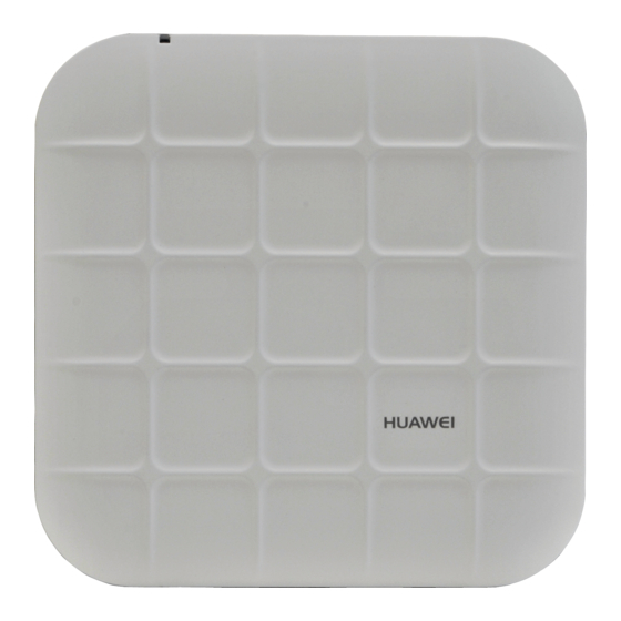
Huawei AP4030DN Hardware Installation and Maintenance Guide 1 AP Overview AP Overview 1.1 Device Structure Figure 1-1 show the appearance of AP4030DN Figure 1-1 Appearance of AP4030DN Table 1-1 describes interfaces on AP4030DN. Table 1-1 Interfaces on AP4030DN Name Description... -
Page 6: Indicator Description
Default Reset button: restores factory settings if you hold down the button more than 1.2 Indicator Description AP4030DN provide only a single indicator, as shown in Figure 1-2. The actual indicator color may vary according to temperature. After an AP is powered on, you can run the led off command on the AC to turn off all AP indicators. - Page 7 Huawei AP4030DN Hardware Installation and Maintenance Guide 1 AP Overview Table 1-2 Description of the indicator on the AP4030DN Type Color Status Description Default status after The AP is just Green Steady on power-on powered on and the software is not started yet.
-
Page 8: Basic Specifications
The fault cannot be automatically rectified and must be rectified manually. 1.3 Basic Specifications Table 1-3 Basic specifications of the AP4030DN Item Description Technical specifications Dimensions (H x W x D) 39.5mm x 180mm x 180mm Weight 0.4kg... -
Page 9: Ordering Information
5% to 95% Operating humidity (non-condensing) Ingress Protection Rating IP41 Atmospheric pressure 70kPa to 106kPa 1.4 Ordering Information To place an order, contact the Huawei local office. Part Number Description 50082641 Broadband Network Terminal,AP4030DN,2*RJ45,11ac, 2*2 Double Frequency 50082642 Broadband Network... -
Page 10: Ap Installation
To install APs, prepare tools listed in Table 2-1. Table 2-1 Tools Phillips screwdriver Torque screwdriver Marker (M3-M6) 3mm/5mm (M3-M6) Hammer drill (φ6) Utility knife Cable cutter Issue 02 (2015-05-18) Huawei Proprietary and Confidential Copyright © Huawei Technologies Co., Ltd. -
Page 11: Installation Flowchart
Network cable tester Multimeter Inner hexagon wrench (M6) Ladder Adjustable wrench Rubber mallet ESD gloves Level 2.2 Installation Flowchart The following figure shows the process for installing an AP. Issue 02 (2015-05-18) Huawei Proprietary and Confidential Copyright © Huawei Technologies Co., Ltd. -
Page 12: Unpacking The Equipment
Power adapter (optional) Adjustable buckle Expansion screws OT terminal Quick Start Guide Warranty card MAC address label SN label Issue 02 (2015-05-18) Huawei Proprietary and Confidential Copyright © Huawei Technologies Co., Ltd. -
Page 13: Determining The Installation Position
The installation position is determined by the site survey. Leave at least 200 mm of clearance around the device. Figure 2-2 shows dimensions of the AP4030DN. Figure 2-2 Dimensions of an AP4030DN (unit: mm) 2.5 Installing the AP If the AP surface is covered with protective film, remove it before installation. 2.5.1 Wall Mounting Mounting APs on a wall requires sheet metal mounting brackets and expansion screws. - Page 14 Align the mounting screws at the rear of the AP with the mounting holes on the sheet metal mounting bracket and then press the AP downwards to secure the AP on the bracket. Issue 02 (2015-05-18) Huawei Proprietary and Confidential Copyright © Huawei Technologies Co., Ltd.
-
Page 15: Ceiling Mounting
Hang the AP on the mounting holes by aligning the mounting screws at the rear of the AP with the mounting holes on the bracket and push the AP horizontally to secure the Issue 02 (2015-05-18) Huawei Proprietary and Confidential Copyright © Huawei Technologies Co., Ltd. -
Page 16: T-Rail Mounting
Hang the AP on the mounting holes by aligning the mounting screws at the rear of the AP with the mounting holes on the bracket and push the AP horizontally to secure the Issue 02 (2015-05-18) Huawei Proprietary and Confidential Copyright © Huawei Technologies Co., Ltd. -
Page 17: Connecting Cables
Ensure that the AP is correctly installed on the mounting bracket and there must be 200 mm space above and around the AP for maintenance. 2.6 Connecting Cables Figure 2-3 show the appearance of AP4030DN. Figure 2-3 Appearance of AP4030DN Table 2-2 Cable connections Cable Description... -
Page 18: Installing The Security Lock
There is a security slot on the AP. You can lock the AP to an immovable object to prevent the AP against theft. The detailed procedures are as follows: Issue 02 (2015-05-18) Huawei Proprietary and Confidential Copyright © Huawei Technologies Co., Ltd. -
Page 19: Checking The Ap After Installation
Labels on cables, feeders, or jumpers are clear and correct. 2.9 Powering on the AP You can check the power-on status by observing indicators on the AP. For details, see Indicator Description. Issue 02 (2015-05-18) Huawei Proprietary and Confidential Copyright © Huawei Technologies Co., Ltd. - Page 20 Huawei AP4030DN Hardware Installation and Maintenance Guide 2 AP Installation Do not frequently power on and off an AP. Issue 02 (2015-05-18) Huawei Proprietary and Confidential Copyright © Huawei Technologies Co., Ltd.
-
Page 21: Logging In To The Ap
(The following information is only for reference.) FIT AP: Login authentication Username: Password: Info: You are advised to change the password to ensure FAT AP: Login authentication Password: Issue 02 (2015-05-18) Huawei Proprietary and Confidential Copyright © Huawei Technologies Co., Ltd. -
Page 22: Logging In To The Ap Using Stelnet
Huawei AP4030DN Hardware Installation and Maintenance Guide 3 Logging In to the AP For the FIT AP, the default user name and password are respectively admin and admin@huawei.com. For the FAT AP, the default password is admin@huawei.com When you log in to the system again in password authentication mode, enter the password that is set ... -
Page 23: Logging In To The Ap Using A Web Client
3.3 Logging In to the AP Using a Web Client Pre-configuration Tasks Before configuring users to log in to the AP using HTTP, complete the following task: Configure reachable routes between the terminal and the AP. Issue 02 (2015-05-18) Huawei Proprietary and Confidential Copyright © Huawei Technologies Co., Ltd. - Page 24 169.254.1.1 and the mask is 255.255.0.0. The web management system provides a default user account, with the user name admin and password admin@huawei.com. You are advised to change the user name and password on your first login. Assign your PC an IP address on the same network segment as the default IP address of the web management system, and connect the PC to the GE interface.
-
Page 25: Hardware Failures
The line is faulty (the network cable or distribution frame is damaged). The AP is faulty. Issue 02 (2015-05-18) Huawei Proprietary and Confidential Copyright © Huawei Technologies Co., Ltd. - Page 26 4. If the device still cannot be powered on, the device itself is faulty. Contact Huawei technical support engineers or Huawei agent and ask them to replace the device. Issue 02 (2015-05-18) Huawei Proprietary and Confidential...
-
Page 27: Appendix
conductors between pins or between pins and the shell. Precautions for Assembly Use dedicated tools or tools delivered by Huawei and follow the methods given here during assembly. Hold terminals of cables instead of pulling the cables when installing or removing cable ... -
Page 28: Assembling Power Cables
Step 1 Based on the cross-sectional area of the cable conductor, strip a length of insulation coating C to expose the conductor D of length L1, as shown in Figure 5-2. The recommended values of L1 are listed in Table 5-1. Issue 02 (2015-05-18) Huawei Proprietary and Confidential Copyright © Huawei Technologies Co., Ltd. - Page 29 When you strip a power cable, do not damage the conductor of the cable. If the bare crimping terminal is not provided by Huawei, the value of L1 is 1 mm (0.04 in.) to 2 mm (0.08 in.) greater than the value of L.
- Page 30 Step 5 Push the heat shrink tubing (A) towards the connector until the tube covers the crimped part, and then heat the tube by using a heat gun, as shown in Figure 5-5. Issue 02 (2015-05-18) Huawei Proprietary and Confidential Copyright © Huawei Technologies Co., Ltd.
- Page 31 Figure 5-6 Components of a JG terminal and a power cable A. JG B. Heat-shrinkable C. Insulation layer of a D. Conductor of a terminal tube power cable power cable Issue 02 (2015-05-18) Huawei Proprietary and Confidential Copyright © Huawei Technologies Co., Ltd.
- Page 32 5-2. When you strip a power cable, do not damage the conductor of the cable. If the bare crimping terminal is not provided by Huawei, you can adjust the value of L as required. Figure 5-7 Stripping a power cable (JG terminal)
- Page 33 Step 5 Push the heat shrink tubing towards the connector until the tube covers the crimped part, and then heat the tube by using a heat gun, as shown in Figure 5-10. Issue 02 (2015-05-18) Huawei Proprietary and Confidential Copyright © Huawei Technologies Co., Ltd.
- Page 34 Step 1 Based on the cross-sectional area of the cable conductor, strip a part of the insulation. The L1-long conductor is exposed, as shown in Figure 5-12. The recommended values of L1 are listed in Table 5-3. Issue 02 (2015-05-18) Huawei Proprietary and Confidential Copyright © Huawei Technologies Co., Ltd.
- Page 35 Figure 5-13. After the conductor is fed into the cord end terminal, the protruding part of the conductor must not be longer than 1 mm (0.04 in.). Issue 02 (2015-05-18) Huawei Proprietary and Confidential Copyright © Huawei Technologies Co., Ltd.
- Page 36 0.5 (0.0008) 1 (0.04) 1.0 (0.0015) 1.5 (0.06) 1.5 (0.0023) 1.5 (0.06) 2.5 (0.0039) 2.4 (0.09) 4 (0.006) 3.1 (0.12) 6 (0.009) 4 (0.16) 10 (0.015) 5.3 (0.21) Issue 02 (2015-05-18) Huawei Proprietary and Confidential Copyright © Huawei Technologies Co., Ltd.
-
Page 37: Assembling Ethernet Cables
F. Shield layer of G. Twisted-pair wires Ethernet cable Ethernet cable Procedure Step 1 Fit the jacket of the connector onto the Ethernet cable, as shown in Figure 5-16. Issue 02 (2015-05-18) Huawei Proprietary and Confidential Copyright © Huawei Technologies Co., Ltd. - Page 38 Figure 5-17 Removing the jacket of a twisted-pair cable (unit: mm (in.)) Step 3 Fit the metal shell onto the twisted-pair cable. The shield layer is covered by the metal shell, as shown in Figure 5-18. Issue 02 (2015-05-18) Huawei Proprietary and Confidential Copyright © Huawei Technologies Co., Ltd.
- Page 39 Step 5 Based on the colors, lead the four pairs of twisted-pair wires through the wire holder, as shown in Figure 5-20 Figure 5-21. Figure 5-20 Leading wires through the wire holder Issue 02 (2015-05-18) Huawei Proprietary and Confidential Copyright © Huawei Technologies Co., Ltd.
- Page 40 5-22. The connections between the wires and the pins are shown in Figure 5-23 and listed in Table 5-5. Figure 5-22 Four pairs of cables on a wire holder Issue 02 (2015-05-18) Huawei Proprietary and Confidential Copyright © Huawei Technologies Co., Ltd.
- Page 41 Orange White-Green Blue White-Blue Green White-Brown Brown Step 7 Cut off the surplus cables along the lower edge of the wire holder, as shown in Figure 5-24. Issue 02 (2015-05-18) Huawei Proprietary and Confidential Copyright © Huawei Technologies Co., Ltd.
- Page 42 Step 9 Push the metal shell towards the connector body until the wire holder and the connector body are engaged completely. Crimp the connector, as shown in Figure 5-26. Figure 5-26 Crimping the connector Issue 02 (2015-05-18) Huawei Proprietary and Confidential Copyright © Huawei Technologies Co., Ltd.
- Page 43 A. Plug of connector B. Jacket C. Twisted-pair wires Procedure Step 1 Remove a 16-mm (0.63 in.) long section of the jacket, as shown in Figure 5-29. Issue 02 (2015-05-18) Huawei Proprietary and Confidential Copyright © Huawei Technologies Co., Ltd.
- Page 44 Wire Color White-Orange Orange White-Green Blue White-Blue Green White-Brown Brown Step 3 Feed the cable into the plug, and crimp the connector, as shown in Figure 5-31. Issue 02 (2015-05-18) Huawei Proprietary and Confidential Copyright © Huawei Technologies Co., Ltd.
- Page 45 Figure 5-32 shows an unqualified piece, and Figure 5-33 shows a qualified piece. All unqualified pieces must be crimped again. Issue 02 (2015-05-18) Huawei Proprietary and Confidential Copyright © Huawei Technologies Co., Ltd.
- Page 46 Step 3 Check whether the contact strips are clean. If they are not clean and the dirt cannot be removed, replace it with a new RJ45 connector. Figure 5-35 shows an unqualified piece. Issue 02 (2015-05-18) Huawei Proprietary and Confidential Copyright © Huawei Technologies Co., Ltd.
- Page 47 If not, replace the connector. Figure 5-37 shows an unqualified piece. Figure 5-37 Wires not in good contact with the edge of the RJ45 ----End Issue 02 (2015-05-18) Huawei Proprietary and Confidential Copyright © Huawei Technologies Co., Ltd.
- Page 48 5 Appendix Testing the Connection of Assembled Cables Context Huawei provides two types of Ethernet cables: straight-through cables and crossover cables. Straight-through cables are connected in a one-to-one manner. They are used to connect terminals such as a computer or switch to network devices.
- Page 49 Step 3 Gently shake the connector and repeat Step 2 to check whether the metal contact strips are in good contact with the core wires and Ethernet ports, as shown in Figure 5-40. Issue 02 (2015-05-18) Huawei Proprietary and Confidential Copyright © Huawei Technologies Co., Ltd.
- Page 50 If a tester is not available, you can use a multimeter to perform a simple test, as shown in Figure 5-41. Figure 5-41 Testing the connection of an Ethernet cable Issue 02 (2015-05-18) Huawei Proprietary and Confidential Copyright © Huawei Technologies Co., Ltd.
-
Page 51: Installing Cable Accessories
For example, in this document, the adapters of cable connectors have separate interfaces. In the actual situation, the adapters may have interfaces fixed on equipment. Use dedicated tools provided or specified by Huawei and follow the installation procedure described here. - Page 52 Figure 5-42 Aligning the OT terminal with a connecting hole When you install an OT terminal, the crimping sleeve is installed as shown in Figure 5-43, where A is correct and B is wrong. Issue 02 (2015-05-18) Huawei Proprietary and Confidential Copyright © Huawei Technologies Co., Ltd.
- Page 53 Ensure that the OT terminal is not in contact with other terminals or metal components. Move the cable slightly and ensure that it is securely connected, as shown in Figure 5-45. Issue 02 (2015-05-18) Huawei Proprietary and Confidential Copyright © Huawei Technologies Co., Ltd.
- Page 54 Bend the upper OT terminal at a 45- or 90-degree angle, as shown in Figure 5-46. − Cross the two terminals, as shown in Figure 5-47. − Figure 5-46 Bending the upper OT terminal at a 45- or 90-degree angle Issue 02 (2015-05-18) Huawei Proprietary and Confidential Copyright © Huawei Technologies Co., Ltd.
- Page 55 Step 2 Insert the terminal into the jack vertically, and fasten the terminal by turning the matching screw in the clockwise direction, as shown in Figure 5-49. Issue 02 (2015-05-18) Huawei Proprietary and Confidential Copyright © Huawei Technologies Co., Ltd.
- Page 56 Step 1 Hold the male and female connectors, with the male connector facing the female connector, as shown in Figure 5-50. Figure 5-50 Holding the male and female shielded connectors Issue 02 (2015-05-18) Huawei Proprietary and Confidential Copyright © Huawei Technologies Co., Ltd.
- Page 57 5-52. Figure 5-52 Installed shielded Ethernet connector Step 4 To remove an Ethernet connector, press the locking key and pull out the connector, as shown Figure 5-53. Issue 02 (2015-05-18) Huawei Proprietary and Confidential Copyright © Huawei Technologies Co., Ltd.
- Page 58 Figure 5-54. Figure 5-54 Holding the male and female unshielded connectors Step 2 Feed the male connector into the female connector, as shown in Figure 5-55. Issue 02 (2015-05-18) Huawei Proprietary and Confidential Copyright © Huawei Technologies Co., Ltd.
- Page 59 Figure 5-56 Installed unshielded Ethernet connector Step 4 To remove an Ethernet connector, press the locking key and pull out the connector, as shown Figure 5-57. Issue 02 (2015-05-18) Huawei Proprietary and Confidential Copyright © Huawei Technologies Co., Ltd.
- Page 60 Step 1 Remove the dustproof cap of the FC connector and store it for future use. Step 2 Align the core pin of the male connector with that of the female connector, as shown in Figure 5-58. Issue 02 (2015-05-18) Huawei Proprietary and Confidential Copyright © Huawei Technologies Co., Ltd.
- Page 61 Figure 5-59 Feeding the male connector into the female connector Step 4 Fasten the locking nut in the clockwise direction and ensure that the connector is securely installed, as shown in Figure 5-60. Issue 02 (2015-05-18) Huawei Proprietary and Confidential Copyright © Huawei Technologies Co., Ltd.
- Page 62 Step 1 Remove the dustproof cap of the LC fiber connector and store it for future use. Step 2 Align the core pin of the male connector with that of the female connector, as shown in Figure 5-62. Issue 02 (2015-05-18) Huawei Proprietary and Confidential Copyright © Huawei Technologies Co., Ltd.
- Page 63 Step 5 To disassemble an LC fiber connector, press the locking nut to release the locking clips from the bore, and gently pull the male connector, as shown in Figure 5-65. Issue 02 (2015-05-18) Huawei Proprietary and Confidential Copyright © Huawei Technologies Co., Ltd.
- Page 64 (not the pigtail). When you hear a click, the fiber connector is secured by the clips (internal parts, not illustrated in the figure). Pull the fiber connector gently. If the connector does not loosen, the installation is complete. See Figure 5-67. Issue 02 (2015-05-18) Huawei Proprietary and Confidential Copyright © Huawei Technologies Co., Ltd.
- Page 65 Step 1 Remove the dustproof cap of the MPO fiber connector and store it for future use. Step 2 Align the core pin of the male connector with that of the female connector, as shown in Figure 5-69. Issue 02 (2015-05-18) Huawei Proprietary and Confidential Copyright © Huawei Technologies Co., Ltd.
- Page 66 Figure 5-70 Installed MPO fiber connector Step 4 To disassemble an MPO fiber connector, hold the shell labeled "PULL" and remove the male connector, as shown in Figure 5-71. Issue 02 (2015-05-18) Huawei Proprietary and Confidential Copyright © Huawei Technologies Co., Ltd.
-
Page 67: Replacing The Mold Of The Crimping Pliers
Step 2 Hold the handles of the COAX crimping tools to open the self-locking mechanism. The jaw of the COAX crimping tools opens automatically, as shown in Figure 5-73. Issue 02 (2015-05-18) Huawei Proprietary and Confidential Copyright © Huawei Technologies Co., Ltd. - Page 68 Figure 5-74 Removing the mould from the COAX crimping tools Step 4 Place the mould to be installed into the jaw of the COAX crimping tools and align the screw holes, as shown in Figure 5-75. Issue 02 (2015-05-18) Huawei Proprietary and Confidential Copyright © Huawei Technologies Co., Ltd.
- Page 69 Step 6 Hold the handles of the COAX crimping tools with one hand. Tighten the two fastening screws in the clockwise direction. Figure 5-77 Figure 5-78shows the mould installed in the COAX crimping tools. Issue 02 (2015-05-18) Huawei Proprietary and Confidential Copyright © Huawei Technologies Co., Ltd.
-
Page 70: Environmental Requirements For Device Operation
The equipment room should be located at a place free from high temperature, dust, toxic gases, explosive materials, or unstable voltage. Keep the equipment room away from significant vibrations or strong noises, as well as power transformer stations. Issue 02 (2015-05-18) Huawei Proprietary and Confidential Copyright © Huawei Technologies Co., Ltd. - Page 71 To ensure easy maintenance and management, place the telecom equipment in different rooms. Figure 5-79 shows the layout of the equipment room. Issue 02 (2015-05-18) Huawei Proprietary and Confidential Copyright © Huawei Technologies Co., Ltd.
- Page 72 The door of the equipment room should be 2 m (6.56 ft) high and 1 m windows (3.28 ft) wide. One door is enough. Seal the doors and windows with Issue 02 (2015-05-18) Huawei Proprietary and Confidential Copyright © Huawei Technologies Co., Ltd.
- Page 73 This problem can shorten the life span of devices and cause faults. The equipment room must be free from explosive, conductive, magnetically-permeable, and corrosive dust. Table 5-11 shows the requirement for dust concentration in the equipment room. Issue 02 (2015-05-18) Huawei Proprietary and Confidential Copyright © Huawei Technologies Co., Ltd.
- Page 74 Avoid constructing the room near a place where the corrosive gas concentration is high, such as a chemical plant. Ensure the air intake vent of the room is in the prevailing upwind direction from the pollution source. Issue 02 (2015-05-18) Huawei Proprietary and Confidential Copyright © Huawei Technologies Co., Ltd.
- Page 75 AC voltage stabilizer and equipment room the AC power distribution panel (box). Ground the arrester nearby need to be and correctly. Issue 02 (2015-05-18) Huawei Proprietary and Confidential Copyright © Huawei Technologies Co., Ltd.
- Page 76 Signal cables should be deployed on internal walls. Do not deploy outdoor aerial cables. Keep signal cables away from power cables and surge protection Issue 02 (2015-05-18) Huawei Proprietary and Confidential Copyright © Huawei Technologies Co., Ltd.
- Page 77 0.5 m (1.64 ft.) segment from the reinforcing rib. Wrap the reinforcing rib with at least five layers of insulation tape. Keep the reinforcing rib at least 5 cm (1.969 in.) from the cabinet surface. Issue 02 (2015-05-18) Huawei Proprietary and Confidential Copyright © Huawei Technologies Co., Ltd.
-
Page 78: Requirements For Power Supply
Low-voltage power distribution rooms should comply with local regulations. Recommendations for AC Power Supply The following shows recommendations for the AC power supply. Issue 02 (2015-05-18) Huawei Proprietary and Confidential Copyright © Huawei Technologies Co., Ltd. - Page 79 1%. Overshoot Integral value of the DC output voltage ± 5% amplitude of switch on/off Peak noise ≤200 mV voltage Issue 02 (2015-05-18) Huawei Proprietary and Confidential Copyright © Huawei Technologies Co., Ltd.
-
Page 80: Equipment Grounding Specifications
The ground cable must be connected securely to the protection ground bar of the equipment room. Do not use other equipment as part of the ground cable or electrical connection. Issue 02 (2015-05-18) Huawei Proprietary and Confidential Copyright © Huawei Technologies Co., Ltd. -
Page 81: Grounding Specifications For An Equipment Room
Connect the two ends of the short-circuiting cable to the ground busbar terminals of neighboring cabinets and fix them firmly. 5.3.4 Grounding Specifications for Communications Power Supply Table 5-18 shows the grounding specifications for communication power supplies. Issue 02 (2015-05-18) Huawei Proprietary and Confidential Copyright © Huawei Technologies Co., Ltd. -
Page 82: Grounding Specifications For Signal Cables
The MDF should use the same grounding conductor with the cabinet. The signal cables should not be routed overhead. 5.3.6 Specifications for Laying Out Grounding Cables Table 5-20 shows the specifications for the ground cable. Issue 02 (2015-05-18) Huawei Proprietary and Confidential Copyright © Huawei Technologies Co., Ltd. -
Page 83: Engineering Labels For Cables
Ambient temperature: -29° C (-20.2° F) to +149° C (300.2° F) Compatible with laser printing and handwriting with markers Pass UL and CSA authentication Issue 02 (2015-05-18) Huawei Proprietary and Confidential Copyright © Huawei Technologies Co., Ltd. - Page 84 The identification plate has an embossed area 0.2 mm x 0.6 mm (0.008 in. x 0.02 in.) around (symmetric on both sides), and the area in the middle is for affixing the label, as shown in Figure 5-82. Issue 02 (2015-05-18) Huawei Proprietary and Confidential Copyright © Huawei Technologies Co., Ltd.
- Page 85 Template for Printing Use a template to print labels. You can obtain the template from the Huawei local office. The templates are made in Microsoft Word and the following requirements should be met: Issue 02 (2015-05-18) Huawei Proprietary and Confidential Copyright ©...
- Page 86 After the page setup has been made correctly, save it for future use. This page setup is only necessary the first time you use the template to print the labels. Issue 02 (2015-05-18) Huawei Proprietary and Confidential Copyright © Huawei Technologies Co., Ltd.
- Page 87 Table 5-21 Standard typeface for handwriting Determine the size of characters based on the number of letters or digits and ensure that the characters are clear, distinct, and tidy. Issue 02 (2015-05-18) Huawei Proprietary and Confidential Copyright © Huawei Technologies Co., Ltd.
- Page 88 The identification card should be downward when you lay out the cable horizontally. − Figure 5-85 Text area of the label Procedure for attaching labels Figure 5-86 shows the methods and procedures for attaching labels. Issue 02 (2015-05-18) Huawei Proprietary and Confidential Copyright © Huawei Technologies Co., Ltd.
- Page 89 The identification card is to the right of the cable in vertical cabling. The identification card is on the top of the cable in horizontal cabling. Make sure that the label is facing out. Issue 02 (2015-05-18) Huawei Proprietary and Confidential Copyright © Huawei Technologies Co., Ltd.
- Page 90 The side with "TO:" that is facing outside carries the location information of the opposite end; and the other side carries the location information of the local end. Issue 02 (2015-05-18) Huawei Proprietary and Confidential Copyright © Huawei Technologies Co., Ltd.
-
Page 91: Engineering Labels For Optical Fibers
01. For example, 01 is the slot with number 1. D: optical Numbered in a top-bottom and left-right order, interface consistent with the port sequence number on the number. device. Issue 02 (2015-05-18) Huawei Proprietary and Confidential Copyright © Huawei Technologies Co., Ltd. - Page 92 01. For example, 01 is the slot with number 1. D: optical Numbered in a top-down and left-right order, interface consistent with the port sequence number on the Issue 02 (2015-05-18) Huawei Proprietary and Confidential Copyright © Huawei Technologies Co., Ltd.
- Page 93 "ODF-G01-01-01-R" indicates that the local end of the optical fiber is connected to the optical receiving terminal on row 01, column 01 of the ODF in row G, column 01 in the machine room. Issue 02 (2015-05-18) Huawei Proprietary and Confidential Copyright © Huawei Technologies Co., Ltd.
-
Page 94: Engineering Labels For Network Cables
The label on the device end should indicate the number of the chassis and cabinet where the device is located. If the device is a stand-alone device, the specific position of the device should be provided. Issue 02 (2015-05-18) Huawei Proprietary and Confidential Copyright © Huawei Technologies Co., Ltd. -
Page 95: Engineering Labels For User Cables
C: physical slot Numbered with two digits in the top-down and number left-right order. For example, 01. D: cable number Numbered with two digits in the top-down and Issue 02 (2015-05-18) Huawei Proprietary and Confidential Copyright © Huawei Technologies Co., Ltd. -
Page 96: Engineering Labels For Power Cables
The labels for DC power cables are affixed to one side of the identification plates on cable ties. For details of the labels, see Table 5-26. Table 5-26 Contents of the label Content Meaning MN(BC)-B--48V MN(BC): BC is written right under MN. Issue 02 (2015-05-18) Huawei Proprietary and Confidential Copyright © Huawei Technologies Co., Ltd. - Page 97 -48 V connector bar has a numeric identification. For example, in the above label of "A01/B08--48V2", "08" (or sometimes "8") is the numeric identification of the terminal block. Issue 02 (2015-05-18) Huawei Proprietary and Confidential Copyright © Huawei Technologies Co., Ltd.
- Page 98 Figure 5-94. Issue 02 (2015-05-18) Huawei Proprietary and Confidential Copyright © Huawei Technologies Co., Ltd.
-
Page 99: Guide To Using Optical Modules
If the latch boss is not secured, the gold finger of the optical module is not in good contact with the connector on the board. In this case, the link may be connected but Issue 02 (2015-05-18) Huawei Proprietary and Confidential Copyright © Huawei Technologies Co., Ltd. - Page 100 Cover an unused optical module with a protective cap to prevent dust, as shown in Figure 5-97. Issue 02 (2015-05-18) Huawei Proprietary and Confidential Copyright © Huawei Technologies Co., Ltd.
- Page 101 Clean a receptacle with a cotton swab, as shown in Figure 5-100. Clean an optical connector with cleaning tissues. Issue 02 (2015-05-18) Huawei Proprietary and Confidential Copyright © Huawei Technologies Co., Ltd.
-
Page 102: Fault Tag
For example, optical signals will be lost. 5.6 Fault Tag *Customer name: Address: Contact person: Tel.: Fax: Category*: □ RMA □ Return □ Analysis Issue 02 (2015-05-18) Huawei Proprietary and Confidential Copyright © Huawei Technologies Co., Ltd. - Page 103 One Fault Tag should be adapted in one return category, such as RMA/Return/Analysis. The items marked with "*" are the mandatory fields that you must fill in. Issue 02 (2015-05-18) Huawei Proprietary and Confidential Copyright © Huawei Technologies Co., Ltd.