Table of Contents
Advertisement
Quick Links
Download this manual
See also:
User Manual
Advertisement
Table of Contents

Related Manuals for Honeywell HDZ20HD


Summary of Contents for Honeywell HDZ20HD
-
Page 1: User Manual
HDZ Series 1080p IP PTZ Dome HDZ20HD HDZ20HDX HDZ20HDE HDZ20HDEX User Manual Document 800-11873V2 – Rev A – 07/2013... - Page 2 Revisions Issue Date Revisions 07/2012 New document. V1 Rev A 09/2012 Revised for NA compatibility, and few corrections made to reflect product development. V2 Rev A 07/2013 Revised for regulatory corrections based on product UL report.
-
Page 3: Cautions And Warnings
Cautions and Warnings RISK OF ELECTRIC SHOCK DO NOT OPEN CAUTION: TO REDUCE THE RISK OF ELECTRIC SHOCK, DO NOT REMOVE COVER (OR BACK). NO USER SERVICEABLE PARTS INSIDE. REFER SERVICING TO QUALIFIED SERVICE PERSONNEL. WARNING Installation and servicing should be performed only by qualified and experienced technicians to conform to all local codes and to maintain your warranty. -
Page 4: Safety Instructions
POWER SOURCES - This product should be operated only from the type of power source indicated on the marking label. HEAT - Situate away from items that produce heat or are heat sources such as radiators, heat registers, stoves, or other products (including amplifiers). www.honeywell.com/security... -
Page 5: Warranty And Service
Honeywell will repair or replace, at its sole option, free of charge, any defective products returned prepaid. In the event you have a problem with any Honeywell product, please call Customer Service at 1.800.323.4576 for assistance or to request a Return Merchandise Authorization (RMA) number. - Page 6 6 | HDZ Series 1080p IP PTZ User Manual www.honeywell.com/security...
-
Page 7: Table Of Contents
Installing and Using Honeywell Viewer for the First Time......32 Deleting the Honeywell Viewer Program from a PC ......33 Understanding the Web Client User Interface . - Page 8 Security Settings ..........93 www.honeywell.com/security...
- Page 9 Contents | 9 User Settings ..........94 Network Security Settings .
- Page 10 10 | HDZ Series 1080p IP PTZ User Manual www.honeywell.com/security...
- Page 11 Figures Figure 1-1 HDZ20HD(X) Indoor IP PTZ Dome Camera ......18 Figure 1-2 HDZ20HDE(X) Outdoor IP PTZ Dome Camera .
- Page 12 Figure B-1 In-Ceiling Bracket Dimensions ........123 www.honeywell.com/security...
- Page 13 Table 2-2 Honeywell Mounts and Adapters ........20 Table 2-3 Camera Back Plate Connectors, Switches, and Buttons .
- Page 14 14 | HDZ Series 1080p IP PTZ User Manual www.honeywell.com/security...
-
Page 15: About This Document
| 15 About This Document This document provides instructions for installing, configuring, and operating the HDZ Series 1080p IP PTZ dome camera. This document is intended for system installers, administrators, and operators. Overview of Contents This document contains the following chapters and appendixes: •... -
Page 16: Related Documents
Buttons you click to perform actions Click Exit to close the program. Italic Placeholders: words that vary depending on the Enter your user name. situation Cross-reference to external source Refer to the System Administrator Guide. Cross-reference within document Chapter 2, Installation. www.honeywell.com/security... -
Page 17: Introduction
Dimensions, page 18 Overview The Honeywell HDZ Series 1080p IP PTZ dome camera is a high resolution network camera designed for use in a wide range of video surveillance applications. The camera supports H.264 main profile compression and streams video at 30 frames per second (NTSC), or 25 fps (PAL) at 1080p resolution. -
Page 18: Dimensions
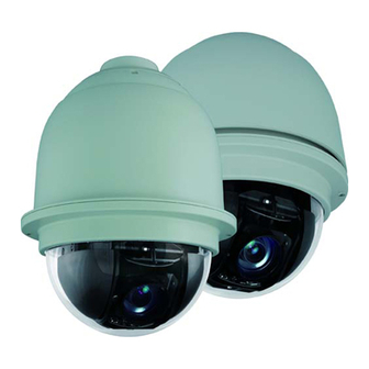
18 | HDZ Series 1080p IP PTZ User Manual Dimensions The indoor and outdoor HDZ Series cameras have the following dimensions: Figure 1-1 HDZ20HD(X) Indoor IP PTZ Dome Camera 7.56 in. (192.00 mm) Figure 1-2 HDZ20HDE(X) Outdoor IP PTZ Dome Camera 7.55 in. -
Page 19: Installing The Camera
Connecting the Cables, page 25 Before You Begin Before you begin, check that you have received all of the parts listed below. If any parts are missing or damaged, contact your dealer immediately. HDZ20HD(X) Indoor Dome Lubricant Honeywell logo label... -
Page 20: Accessories You Can Order Separately
Leave the protective film on the dome cover until installation is complete. Mounting the Camera You can install the camera to a ceiling, wall, pole, parapet, or roof using one of the following Honeywell products: Table 2-2 Honeywell Mounts and Adapters Model No. Description Indoor Outdoor... -
Page 21: Using Safety Cable During Installation
Corner Mount Adapter for HDXWM2 HDXPMA1 Pole Mount Adapter for HDXWM2 Note An In-ceiling mounting bracket (HDZINBKT) is available. Check with your Honeywell supplier regarding In-ceiling mounting. See Appendix B, In-Ceiling Bracket Installation, for in-ceiling bracket mounting instructions. For additional information, see... -
Page 22: Installing A Ceiling Mount (Indoor Only)
Attach the camera to the mount kit and then tightly fix the security screw on the top of the camera. www.honeywell.com/security... -
Page 23: Installing A Wall Mount
Installing the Camera | 23 Installing a Wall Mount The HDXWM2 wall mount weighs 3.2 lb. (1.45 kg) and can be installed directly to a load-bearing wall, or to a corner or pole using an appropriate adapter. The mount has a maximum load rating of 25.8 lb. -
Page 24: Installing A Parapet/Flat Roof Mount
Check that the eyelet safety cable connection is secure, and carrying all of the load of the camera after making all cable connections. Attach the camera to the mount kit and then tightly fix the security screw on the top of the camera. www.honeywell.com/security... -
Page 25: Connecting The Cables
Figure 2-5 Table 2-3 below. Figure 2-5 Camera Back Plate Layout HDZ20HD(X) Indoor Dome Camera HDZ20HDE(X) Outdoor Dome Camera Table 2-3 Camera Back Plate Connectors, Switches, and Buttons RJ45 connector (see Connecting the Network Cable on page 27... -
Page 26: Micro Sdhc Card Details
16 GB Micro SDHC Card (Class 10) MLC/TLC 32 GB 32 GB Micro SDHC Card (Class 10) Note Once installed, all Micro SDHC cards must be formatted using the Honeywell Web GUI software prior to performing any recording. Connecting Audio Refer to Figure 2-6... -
Page 27: Connecting The Network Cable
Installing the Camera | 27 Figure 2-7 Main Alarm Adapter Input (Detail) Inputs (x4) 5V, 4700 Ohms, pull up Outputs (x2) Relay output, AC 120V/DC 30V 1 2 3 4 5 6 7 8 9 10 11 12 Table 2-6 Alarm Input Pin Definitions Definition Definition... -
Page 28: Connecting Power
Note Please use the minimum power adapter: HDZ20HD(X) Indoor Camera: 24 V AC, 0.8 A / PoE+ 20 W. HDZ20HDE(X) Outdoor Camera: 24 V AC, 2.0 A. Figure 2-8 Main Power Adapter Input (Detail) -
Page 29: Accessing The Camera
(LAN) using the Honeywell Device Search application. This application is included on the installation CD that was shipped with your camera. To find a camera on the network: Insert the installation disc into your disc drive and navigate to the Honeywell Device Search folder. -
Page 30: Assigning A Static Ip Address To The Camera
Copy the Honeywell Device Search executable file to your computer desktop (or other location) to run the Honeywell Device Search without using the installation disc. Launch the Honeywell Device Search application and click Device Search to search for cameras on the network. -
Page 31: Accessing The Camera From A Browser
Accessing the Camera | 31 Note Contact your network administrator for advice on filling in the IP Address, Gateway, Netmask and DNS fields. Figure 3-3 Device Network Setup Window If a static IP address is assigned, users can select the DHCP option to assign the PTZ camera a dynamic IP address. -
Page 32: Accessing The Camera From A Browser
Installing and Using Honeywell Viewer for the First Time The first time you access an HDZ Series 1080p IP PTZ camera, a client program, the Honeywell Viewer, will be automatically installed to your PC when connecting to the camera. If the web browser doesn’t allow the Honeywell Viewer to install, please check the Internet security settings... -
Page 33: Deleting The Honeywell Viewer Program From A Pc
Deleting the Honeywell Viewer Program from a PC For users that have an older version of the Honeywell Viewer already installed on their PC, you should first remove the existing Viewer program before accessing the HDZ Series 1080p IP PTZ camera. -
Page 34: Understanding The Web Client User Interface
HDZ Series Camera Browser Home User Interface Logged in user name Main tabs Focus mode display Time display Live video Language display selection Quick action buttons (see descriptions below) Video format selection Preset controls Mimic tour controls PTZ controls Preset tour controls PTZ speed selection www.honeywell.com/security... -
Page 35: Main Tabs
Accessing the Camera | 35 Main Tabs Table 3-2 Camera Interface Main Tabs Description Home The tab you see upon logging in. Use this tab to view live video, use the PTZ controls to pan, tilt or zoom the camera, perform tours, go to preset positions and use other controls included on the page. -
Page 36: Ptz Controls
Click Set to assign the camera’s current position and view options to the preset number. Preset Goto: To quickly go to a preset point, enter the number of the preset in the field provided and click Goto (see Figure 3-6). The camera will move to the preset position that was previously programmed. www.honeywell.com/security... -
Page 37: On-Screen Display
Accessing the Camera | 37 Table 3-4 PTZ Controls and Functions (cont’d) Control Description Mimic Tour Mimic Tour Run: Select the Mimic Tour line that you want to run with the drop-down list Controls provided (select from tour 1 to 8) and click Run to start the tour (see Figure 3-6). - Page 38 38 | HDZ Series 1080p IP PTZ User Manual www.honeywell.com/security...
-
Page 39: Configuring Video And Audio Streaming
Configuring Video and Audio Streaming Included in this chapter: • Video Format Settings, page 39 • Video Compression Settings, page 45 • Video OCX Protocol Settings, page 47 • Frame Rate Control Settings, page 49 • Audio Settings, page 50 Video Format Settings The HDZ Series 1080p IP PTZ dome camera supports both H.264 and Motion JPEG (MJPEG) video compression standards. -
Page 40: Setting The Video Resolution
1920 x 1080 (13 fps) 1280 x 720 (25 fps) 1920 x 1080 (13 fps) 1280 x 720 (25 fps) 1024 x 768 (25 fps) 1024 x 768 (25 fps) 800 x 600 (25 fps) 800 x 600 (25 fps) www.honeywell.com/security... -
Page 41: Table 4-1 Pal Dual Stream Resolution Options
Configuring Video and Audio Streaming | 41 Table 4-1 PAL Dual Stream Resolution Options (cont’d) MJPEG + H.264 H.264 + H.264 H.264 MJPEG H.264-1 H.264-2 1280 x 1024 (13 fps) 1280 x 1024 (13 fps) 1280 x 720 (25 fps) 1280 x 720 (25 fps) 1024 x 768 (25 fps) 1024 x 768 (25 fps) -
Page 42: Table 4-2 Ntsc Dual Stream Resolution Options
720 x 480 (30 fps) 720 x 480 (30 fps) 800 x 600 (30 fps) 800 x 600 (30 fps) 640 x 480 (30 fps) 640 x 480 (30 fps) 352 x 240 (30 fps) 352 x 240 (30 fps) www.honeywell.com/security... -
Page 43: Table 4-3 Pal/Ntsc Mjpeg Only Stream Resolution Options
Configuring Video and Audio Streaming | 43 Table 4-2 NTSC Dual Stream Resolution Options (cont’d) MJPEG + H.264 H.264 + H.264 H.264 MJPEG H.264-1 H.264-2 720 x 480 (30 fps) 720 x 480 (30 fps) 720 x 480 (30 fps) 640 x 480 (30 fps) 720 x 480 (30 fps) 640 x 480 (30 fps) -
Page 44: Setting The Text Overlay
Click the Streaming tab (Video Format is selected in lefthand column). Under Video Rotate Type, select one of the following options from the drop-down list: • Normal video (default) • Flip video • Mirror video • 90 degree clockwise • 180 degree rotate • 90 degree counterclockwise www.honeywell.com/security... -
Page 45: Setting The Gov Length
Configuring Video and Audio Streaming | 45 Click the Save button directly below the Video Rotate Type drop-down list. Setting the GOV Length The GOV length of an H.264 stream is the sum total of I-frames and P-frames in a GOV (Group of video images). -
Page 46: Figure 4-2 Video Compression Settings
Under H.264-2 Compression setting, in the H.264-2 bit rate field, type a value from 64 to 4096 kbit/s (default = 1024 kbit/s). The higher the bit rate value, image quality increases, and the load on bandwidth also increases. Click the Save button directly below the H.264-2 Compression setting options. www.honeywell.com/security... -
Page 47: Enabling Constant Bit Rate Mode
Note Honeywell recommends that you set your bit rates below the available bandwidth levels of your network to avoid displaying/recording images at a reduced quality during moments of high activity. -
Page 48: Figure 4-3 Video Ocx Protocol Settings
To select an OCX protocol: Navigate to Streaming Video OCX Protocol. Under Video OCX protocol setting, select one of the following options: • RTP over UDP (default) • RTP over RTSP(TCP) • RTSP over HTTP • MJPEG over HTTP • Multicast mode www.honeywell.com/security... -
Page 49: Frame Rate Control Settings
Configuring Video and Audio Streaming | 49 If you selected Multicast mode, enter the required information (IP address, video ports, audio port, and TTL) in the fields given. Click Save. Frame Rate Control Settings If you have limited bandwidth available to transmit images, you can set up the number of image frames to be displayed per second with the Frame Rate control options (see Figure 4-4). -
Page 50: Audio Settings
50 | HDZ Series 1080p IP PTZ User Manual Figure 4-4 Frame Rate Control Settings Audio Settings This section describes how to set the audio transmission mode, gain, and bit rate (see Figure 4-5). Figure 4-5 Streaming Audio Settings www.honeywell.com/security... -
Page 51: Setting The Audio Transmission Mode
Configuring Video and Audio Streaming | 51 Setting the Audio Transmission Mode There are three audio transmission modes, plus the option for disabling audio (see Table 4-6). Table 4-6 Audio Transmission Mode Settings Transmission Mode Description Full-duplex (Talk and The local and remote sites can transmit and receive audio listen simultaneously) (talk and listen) at the same time. - Page 52 52 | HDZ Series 1080p IP PTZ User Manual www.honeywell.com/security...
-
Page 53: Configuring Ptz Settings
Configuring PTZ Settings This chapter includes: • Preset Settings, page 53 • Mimic Tour Settings, page 55 • Auto Pan Settings, page 56 • Preset Tour Settings, page 58 • Home Function, page 60 • Tilt Range Settings, page 61 •... - Page 54 You can also go to a preset on the home page of the PTZ web client interface (see Figure 3-6 page 34). Enter the preset number in the Preset Details field and click Goto to have the camera move to view the selected preset point. www.honeywell.com/security...
-
Page 55: Mimic Tour Settings
Configuring PTZ Settings | 55 Mimic Tour Settings You can program up to eight mimic tours that can be recalled at a later time. To program a mimic tour path: Navigate to PTZ Mimic Tour (see Figure 5-2). Figure 5-2 Mimic Tour Programming Under Mimic Tour setting, in the Mimic Tour path drop-down list, select the number of the Mimic Tour path that you want to program (select from 1 to 8). -
Page 56: Auto Pan Settings
The red arrow icon ( ) indicates the direction that the image will pan/tilt. Use the zoom and focus controls, as needed, to adjust the zoom and focus of the image. www.honeywell.com/security... -
Page 57: Figure 5-3 Auto Pan Programming
Configuring PTZ Settings | 57 Click the Set button located next to Start point (see Figure 5-3). Figure 5-3 Auto Pan Programming In the Direction drop-down list, select a direction for the auto pan path to run (Left or Right). In the Live View screen, use the mouse to click and drag the video image to the end point of the auto pan path, and then click the Set button located next to End point. -
Page 58: Preset Tour Settings
In the Name drop-down list, select the name of the preset point to be part of the tour (see Figure 5-5). In the Dwell time box, type a value from 0 (fast dwell time) to 127 (slow dwell time). In the Speed box, type a value from 0 (low speed) to 14 (high speed). www.honeywell.com/security... -
Page 59: Figure 5-5 Preset Tour Selecting Preset Points
Configuring PTZ Settings | 59 To assign more preset points than the first 15 to the preset tour, click Next page. To return to the previous page, click Pre page. Figure 5-5 Preset Tour Selecting Preset Points When you are finished, click Save to save the preset tour settings that you have entered. To run a preset tour: ... -
Page 60: Home Function
In the Line drop-down list, type or select the number of the PTZ function that you have chosen. The functions available for selection change depending on what Function Type is selected (see step Click the Set button located below the Line field to save the settings that you have entered for the Home Function. www.honeywell.com/security... -
Page 61: Tilt Range Settings
Configuring PTZ Settings | 61 Figure 5-6 Home Function Programming To enable or disable the home function: Navigate to PTZ Home (see Figure 5-6). Under Home setting, in the Switch drop-down list, select one of the following: • On to enable the home function. •... -
Page 62: Privacy Mask Settings
However, the M.E. image flip function (mechanical image flip function) can be used when the privacy masks function is enabled (see Image Flip on page 69 for more information). To create a privacy mask: Navigate to PTZ Privacy Mask (see Figure 5-8). www.honeywell.com/security... -
Page 63: Figure 5-8 Privacy Mask Programming
Configuring PTZ Settings | 63 Under Mask Setting, in the Switch drop-down list, select On to enable the privacy mask function (or select Off to disable the privacy mask feature), and then click the Set button located directly below the drop-down list. In the Transparency drop-down list, select one of the following: •... -
Page 64: Camera Settings
To create a privacy mask:, page 62). Camera Settings This section describes how to set various camera parameters, such as exposure mode, white balance options, backlight compensation, image flip, auto calibration, speed by zoom, ICR function, wide dynamic range, and digital noise reduction. www.honeywell.com/security... -
Page 65: Exposure
Configuring PTZ Settings | 65 Exposure You can select a specific Max Gain value, as needed. You can select one of the following exposure modes to optimize the video output for your operating environment: Table 5-1 Exposure Modes Mode Description Full Auto The camera’s shutter speed, iris, and auto gain control (AGC) circuits work together automatically to produce a consistent video output. -
Page 66: White Balance
Setting up white balance options can compensate for temperature differences with different light sources (such as sunlight, fluorescent light, and so on), and effecting the hue of the color white under different light sources. You can select one of the following white balance modes based on your operating environment: www.honeywell.com/security... -
Page 67: Table 5-2 White Balance Modes
Configuring PTZ Settings | 67 Table 5-2 White Balance Modes Mode Description Auto Suitable for environments with a color temperature range from approximately 2,700K to 7,500K (wide range of light sources). Indoor Suitable for indoor environments with a color temperature range from approximately 2,500K to 3,000K (artificial light sources). -
Page 68: Backlight Compensation
5-11), in the BLC drop-down list, select one of the following: • On to enable backlight compensation. • Off (default) to disable backlight compensation. Click Set to save the setting. Image Sharpness You can adjust the sharpness level of the image: www.honeywell.com/security... -
Page 69: Exposure Compensation
Configuring PTZ Settings | 69 Navigate to PTZ Camera. Under Misc (see Figure 5-11), in the Sharpness drop-down list, type or select a value from 1 (least sharp) to 15 (sharpest) for the camera sharpness level (default is 3). Click Set to save the setting. -
Page 70: Speed By Zoom
Auto (default) The IR cut filter is removed automatically when the image brightness drops below a certain level. Removes the IR cut filter. Leaves the IR cut filter in place. To set the ICR mode: Navigate to PTZ Camera. www.honeywell.com/security... -
Page 71: Wide Dynamic Range
Configuring PTZ Settings | 71 Under Misc (see Figure 5-12), in the ICR function drop-down list, select one of the following: • Auto (default) to remove the IR cut filter automatically. • On to remove the IR cut filter manually. •... -
Page 72: Auto Calibration
The OSD will also provide the degrees that the camera is facing, on both vertical and horizontal axes of rotation. See Figure 3-8 page 37 to see an example of the browser with the on-screen display showing the PTZ information on the video image. www.honeywell.com/security... -
Page 73: Set Pan Zero
Configuring PTZ Settings | 73 To enable/disable on-screen display: Navigate to PTZ Camera. Under Misc (see Figure 5-12), in the OSD drop-down list, select one of the following: • On to enable the on-screen display. • Off (default) to disable the on-screen display. Click Set to save the setting. - Page 74 74 | HDZ Series 1080p IP PTZ User Manual www.honeywell.com/security...
-
Page 75: Configuring Alarms
Configuring Alarms This chapter includes: • Alarm Server Settings, page 75 • Alarm Input Settings, page 78 • Motion Detection Settings, page 83 • Network Failure Detection Settings, page 88 Alarm Server Settings The HDZ Series 1080p IP PTZ dome camera supports four alarm inputs and two alarm outputs. Ensure that the alarm connections are properly wired before configuring alarm-related settings on the camera (see Connecting Alarm Inputs/Outputs on page 26... -
Page 76: Figure 6-1 Setup Mail Server
Under FTP, enter the server name, port, user name, password, and remote folder for each server (see Figure 6-2). To enable passive mode, select the 1st FTP passive mode check box and/or the 2nd FTP passive mode check box. Click Save to save your FTP server settings. www.honeywell.com/security... -
Page 77: Figure 6-2 Setup Ftp Server
Configuring Alarms | 77 Figure 6-2 Setup FTP Server To enable HTTP alarm notifications: Navigate to System HTTP (see Figure 6-3). Under HTTP, enter the server name, user name, and password for each server, and then click Save. Figure 6-3 Setup HTTP Server 800-11873V2 - A - 07/2013... -
Page 78: Alarm Input Settings
Off to disable the alarm. In the Alarm type drop-down list, select one of the following: • Normal open (for the alarm to trigger when the contact is closed). • Normal close (for the alarm to trigger when the contact is opened). www.honeywell.com/security... -
Page 79: Setting The Alarm Actions
Configuring Alarms | 79 Figure 6-5 Alarm Input Parameters Setting the Alarm Actions You can specify what actions you want the camera to perform when the selected alarm is triggered. You can select more than one action. See the following sections for more information. To enable alarm relay output: Under Triggered action (see Figure... -
Page 80: Figure 6-6 Upload Image By Ftp Options
Figure 6-7). Figure 6-7 Upload Image by E-Mail Options In the E-Mail address drop-down list, select either E-Mail 1 or E-Mail 2 (see To enable email alarm notifications: on page 75 for information on setting up an email address). www.honeywell.com/security... -
Page 81: Figure 6-8 Record Stream To Sd Card Options
Configuring Alarms | 81 In the Pre-trigger buffer drop-down list, select the number of pre-trigger frames/images (1 to 20) to send to the server. This option sets the amount of images from before an alarm is triggered that will be uploaded by e-mail. The default setting is 5. In the Post-trigger buffer drop-down list, select the number of post-trigger frames/images (1 to 20) to send to the server. -
Page 82: Setting A File Name
Click Save after you have configured the alarm input settings in the Alarm Application section of the System tab. See Setting the Alarm Status and Type, page Setting the Alarm Actions, page 79, and Setting a File Name on page 82 for more information. www.honeywell.com/security... -
Page 83: Motion Detection Settings
Configuring Alarms | 83 Motion Detection Settings You can set up the camera to send an alarm notification when suspicious motion is detected. An alarm is triggered when motion volume in the detected area reaches and/or exceeds a predefined sensitivity threshold value. You can send a message to an FTP, email, or HTTP server, or you can upload images to an FTP server, email server, or Micro SDHC card when the suspicious motion is detected. -
Page 84: Setting The Motion Detection Sensitivity
1 (every pixel in the motion detection area is sampled for motion). If the sampling interval is set to 3, the system samples every third pixel (vertically and horizontally) within the motion detection area (see Figure 6-13). www.honeywell.com/security... -
Page 85: Setting The Motion Detection Actions
Configuring Alarms | 85 Figure 6-13 Motion Detection Sampling Every Three Pixels You can set the detection level for each sampled pixel. The smaller the value, the greater the sensitivity. To avoid triggering motion detection on small objects in the image, enter a higher value. -
Page 86: Figure 6-14 Upload Image By Ftp Options For Motion Detection
(see Figure 6-15). In the E-Mail address drop-down list, select either E-Mail 1 or E-Mail 2 (see To enable email alarm notifications: on page 75 for information on setting up an email address). www.honeywell.com/security... -
Page 87: Setting A Motion Detection File Name
Configuring Alarms | 87 In the Pre-trigger buffer drop-down list, select the number of pre-trigger frames/images (1 to 20) to send to the server. In the Post-trigger buffer drop-down list, select the number of post-trigger frames/images (1 to 20) to send to the server. Figure 6-15 Upload Image by E-Mail Options for Motion Detection To continue to upload images to the server for a specified time, or until the motion alarm... -
Page 88: Saving The Motion Detection Settings
You can set up the camera to send an alarm notification when a network failure is detected. You can send a message to an FTP or email server, or you can upload images to a Micro SDHC card. To set up network failure detection: Navigate to System Network failure detection (see Figure 6-17). www.honeywell.com/security... -
Page 89: Figure 6-17 Network Failure Detection Options
30 seconds. Note Honeywell recommends that you enter the IP address of the local recording device (DVR, NVR, and/or VMS system) which is used for local hard disk recording. This way, if the Network Failure Detection function detects a network failure with the local recording device, the camera can take an action such as recording to the Micro SDHC card to compensate. - Page 90 90 | HDZ Series 1080p IP PTZ User Manual Click Save to save your network failure detection settings. www.honeywell.com/security...
-
Page 91: Configuring System Settings
Configuring System Settings This chapter includes: • System Settings, page 91 • Security Settings, page 93 • Network Settings, page 100 • Recording and Storage Settings, page 107 • Maintenance Settings, page 111 • Support Settings, page 115 Note The System tab can only be accessed by the Administrator. System Settings The System screen is open by default when the System tab is selected. -
Page 92: Enabling Daylight Saving Time
2nd Sunday in March). If you use the 1st, 2nd, 3rd, 4th or last week of the month option in step b, select the day of the week DST starts/ends with the last drop-down list for the Start/End date. www.honeywell.com/security... -
Page 93: Setting The System Clock
Configuring System Settings | 93 Set the time that daylight saving time changes will take effect in the Start time and End time fields. The format for the time fields is [hh:mm:ss], and uses the 24-hour clock. For instance, if the DST should start at 11:30pm, enter 23:30:00 in the Start time field. Click Save to save your DST settings. -
Page 94: User Settings
User (see Figure 7-2). In the Admin password field, type the new password. In the Confirm password field, re-type the new password, and then click Save. Note The Login window appears. You are asked to login with the new password. www.honeywell.com/security... -
Page 95: Figure 7-2 User Security Options Screen
Configuring System Settings | 95 Figure 7-2 User Security Options Screen Managing Users An administrator can add and delete users, as well as view and edit user privileges. An administrator can create up to 20 user accounts. Each user can be assigned one or more of the following privileges: Table 7-1 User Privileges... -
Page 96: Network Security Settings
To use HTTPS, you must create a certificate. You can create a self-signed certificate or you can create a request for an official certificate issued by a CA (Certificate Authority). www.honeywell.com/security... -
Page 97: Figure 7-3 Https Settings Screen
Configuring System Settings | 97 Note A self-signed certificate does not provide the same level of security as an official certificate. Figure 7-3 HTTPS Settings Screen To create and install a self-signed certificate: Navigate to System Security HTTPS (see Figure 7-3). -
Page 98: Figure 7-4 Create Self-Signed Certificate Window
Enter the required information in the Create Certificate Request fields (see Figure 7-5), and then click OK. Figure 7-5 Create Certificate Request Window A certificate request is created. The request appears under Created Request (see Figure 7-3). Click Properties in the Created Request area. www.honeywell.com/security... -
Page 99: Figure 7-6 Ieee 802.1X Settings Screen
Configuring System Settings | 99 Copy the PEM-formatted request and send to a CA for signing. After the signed certificate is returned, you can install it. To install a CA-issued certificate: Navigate to System Security HTTPS (see Figure 7-3). -
Page 100: Ip Filter
This section contains instructions for assigning the camera a fixed IP address, setting the camera to automatically obtain a DHCP assigned IP address, enabling PPPoE, configuring ports, enabling IPv6 address configuration, prioritizing services, and enabling SNMP, UPnP, and DDNS. www.honeywell.com/security... -
Page 101: Basic Network Settings
Configuring System Settings | 101 Basic Network Settings Assigning a Fixed IP Address The camera is assigned a dynamic (DHCP) IP address by default. Use the Honeywell Device Search tool to find the automatically assigned dynamic IP address (refer to Finding the Camera on a Network on page 29 for more information). -
Page 102: Table 7-2 Ports That Can Be Individually Configured
102 | HDZ Series 1080p IP PTZ User Manual Setting a Dynamically Assigned IP Address The camera is assigned a dynamic (DHCP) IP address by default. Use the Honeywell Device Search tool to find the automatically assigned dynamic IP address (refer to... -
Page 103: Qos (Quality Of Service)
Configuring System Settings | 103 Enabling IPv6 Address Configuration If you are using a routed IPv6 (Internet Protocol version 6) network, you can enable IPv6 address configuration. To enable IPv6 address configuration: Navigate to System Network Basic (see Figure 7-8). -
Page 104: Snmp
SNMP message. To activate trap reporting: Navigate to System Network SNMP (see Figure 7-10). Under Traps for SNMP v1/v2, select the Enable traps check box. In the Trap address field, type the IP address of the management server. www.honeywell.com/security... -
Page 105: Upnp
Configuring System Settings | 105 In the Trap community field, specify the community name to use when sending a trap message to the management server. The default value is <public>. Optionally, select the Warm start check box to have the camera perform a software reload when a trap message is sent. -
Page 106: Figure 7-12 Networking Services Dialog Box
Figure 7-13 UPnP Settings Screen Under UPnP Setting, select the Enable UPnP port forwarding check box and click Save. Note To enable the UPnP function, make sure that your router supports UPnP and that it is activated on your PC. www.honeywell.com/security... -
Page 107: Ddns
Configuring System Settings | 107 DDNS Dynamic DNS (DDNS) service allows dynamic IP addresses to be synchronized to a static host name (domain name). To enable Dynamic DNS: Navigate to System Network DDNS (see Figure 7-14). Select the Enable DDNS check box. Select a DDNS provider from the Provider drop-down list. -
Page 108: Storage Management
It is a good practice to format your Micro SDHC card before using it for the first time. To view the amount of free space remaining on your Micro SDHC card: Insert a Micro SDHC card into the slot on the back of the camera (see Figure 2-5 Table 2-3 page 25). www.honeywell.com/security... -
Page 109: Figure 7-16 Storage Management Settings Screen
Configuring System Settings | 109 Navigate to System Storage Management (see Figure 7-16). The amount of free space on the card is listed under Device information (in the Figure 7-16 example, there is no Micro SDHC card installed, so the free space is 0 KB). To format your Micro SDHC card: ... -
Page 110: File Location
Use the File Location screen to choose the local folder where still images and video clips will be saved. To choose a file location: Navigate to System File Location (see Figure 7-17). Figure 7-17 File Location Setting Screen www.honeywell.com/security... -
Page 111: Maintenance Settings
Configuring System Settings | 111 In the All files stored at field, either type the folder pathway into the field or click Select to browse for, select and save the file location. Click Save to save the file location displayed in the All files stored at field. Maintenance Settings This section describes how to restore the camera to its factory default settings, how to manage your configuration files, and how to upgrade the camera firmware. -
Page 112: Upgrading The Software
The system restarts without changing the current settings. Upgrading the Software To upgrade the firmware: Download the software upgrade file to your hard drive. Make a note of the file location. Navigate to System Software Upgrade (see Figure 7-19). www.honeywell.com/security... -
Page 113: Maintenance Of Configuration Files
Open the Start menu, click Control Panel, and then double-click Add or Remove Programs. Select Honeywell Viewer from the list of programs and then click Remove. Open your web browser and access the camera (see Accessing the Camera from a Browser on page 31). -
Page 114: Figure 7-20 Maintenance Of Configuration Files Screen
Click Upload. The system will start to upload the configuration file (see Figure 7-21). Figure 7-21 Uploading Configuration File In Progress Once the uploading is complete, it is recommended that you clean out the web browser cache and then restart the web browser. www.honeywell.com/security... -
Page 115: Support Settings
Configuring System Settings | 115 Note The configuration file should be uploaded into the PTZ with the same version firmware. Support Settings This sections describes how to view lists of system parameters and system log files. Viewing the System Parameters To view the system parameters list, which lists the configuration settings that have been applied to the system: ... -
Page 116: Viewing The Log File
The system log file provides information to the user about the camera activities. Camera activity information includes: login/logout, alarm in, motion detection, and network failures. To view the system log: Navigate to System Log file (see Figure 7-23 for a system log example). www.honeywell.com/security... -
Page 117: Figure 7-23 Viewing System Log
Configuring System Settings | 117 Figure 7-23 Viewing System Log 800-11873V2 - A - 07/2013... - Page 118 118 | HDZ Series 1080p IP PTZ User Manual www.honeywell.com/security...
-
Page 119: Appendix A Hdz Camera Specifications
HDZ Camera Specifications Table A-1 HDZ20HD(X) Series Camera Specifications Specification Description Camera Specifications Scanning System NTSC / PAL Image Sensor 1/2.8" Sony Progressive CMOS Optical Zoom Number of Pixels (H x V) 1920 x 1080 (1080p) S/N Ratio >50 dB (AGC Off) Minimum Illumination 0.05 lux (color) / 0.01 lux (Black/White) @ F1.6, 30 IRE... - Page 120 120 | HDZ Series 1080p IP PTZ User Manual Table A-1 HDZ20HD(X) Series Camera Specifications (cont’d) Specification Description Operation Specifications (cont’d) Manual Pan Speed 0.5° to 200°/s Manual Tilt Speed 0.5° to 84°/s Presets Preset Accuracy 0.225° Preset Speed Up to 400°/s...
- Page 121 HDZ Camera Specifications | 121 Table A-1 HDZ20HD(X) Series Camera Specifications (cont’d) Specification Description Network Specifications (cont’d) Audio Streaming Full-duplex, Simplex Audio Compression G.711 / G.726 ADPCM / AAC General Specifications Environment Indoor / Outdoor Casing IP66 Standard (Outdoor) Indoor: ø 7.55" x 10.83" (ø 192.00 mm x 275.07 mm) Dimension Outdoor (with sunshield): ø...
- Page 122 122 | HDZ Series 1080p IP PTZ User Manual www.honeywell.com/security...
-
Page 123: Appendix B In-Ceiling Bracket Installation
In-Ceiling Bracket Installation This document describes how to install an HDZ Series camera in a suspended ceiling using the HDZINBKT in-ceiling bracket. CAUTION Installation and servicing should be performed only by qualified and experienced technicians to conform to all local codes and to maintain your warranty. -
Page 124: Package Contents
Ceiling Support Plate, Honeywell Part Number 517082-7130 (not supplied) Installing the In-Ceiling Bracket It is recommended that you use a ceiling support plate (Honeywell part number 517082-7130) when installing the HDZINBKT in-ceiling bracket in a suspended ceiling. Step 1: Cut a hole in the ceiling Select the location where you want to install the camera. - Page 125 In-Ceiling Bracket Installation | 125 Do one of the following: Installation with Ceiling Support Plate Installation without Ceiling Support Plate Remove the ceiling tile at the selected Place the supplied ceiling template on the location and fit the ceiling tile inside ceiling at the selected location and cut the ceiling support plate.
- Page 126 Attach the trim ring to the ceiling support ring by lining up the two magnets on the trim ring with the two thumb screws on the ceiling support ring. Note No screws are needed to attach the trim ring. www.honeywell.com/security...
-
Page 127: Index
| 127 Index Numerics 2DNR. See digital noise reduction backlight compensation bit rates 46, 47, accessing camera from a browser ActiveX settings, enabling in Internet Explorer cables administrator password, changing alarm alarm output audio alarms connections assigning a PTZ camera function crossover configuring inputs network... - Page 128 Honeywell Device Search HTTP notification 82, network failure detection HTTPS 96, NTP server ICR function. See IR cut filter OCX protocol IEEE 802.1X MJPEG over HTTP...
- Page 129 | 129 running speed by zoom presets system clock, setting 91, deleting system requirements going to programming privacy masks text overlay creating tilt angle 61, deleting trap reporting editing position UPnP Quality of Service (QoS) users adding deleting regulatory statements viewing login information related documents viewing privileges...
- Page 130 130 | HDZ Series 1080p IP PTZ User Manual www.honeywell.com/security...
- Page 132 Document 800-11873V2 – Rev A – 07/2013 © 2013 Honeywell International Inc. All rights reserved. No part of this publication may be reproduced by any means without written permission from Honeywell. The information in this publication is believed to be accurate in all respects. However, Honeywell cannot assume responsibility for any consequences resulting from the use thereof.