Table of Contents
Advertisement
Quick Links
Recommended
Find the latest version of this and other HDZ Series IP PTZ dome camera
documents on the Honeywell Video website. Go to
http://www.honeywellvideo.com/products/cameras/ip/pt-onvif/index.html
to find your camera and view/download the latest documentation.
Refer to the Honeywell Open Technology Alliance to learn more
about our open and integrated solutions (go to:
http://www.security.honeywell.com/hota/).
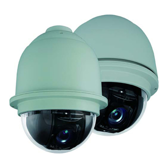
HDZ Series
IP PTZ Dome
HDZ20HD
HDZ20HDE
HDZ20HDEX
HDZ30HD
HDZ30HDE
HDZ30
HDZ36E
User Manual
Document 800-11873V4 – Rev A – 07/2014
HDZ20HDX
HDZ30X
HDZ36EX
Advertisement
Chapters
Table of Contents

Related Manuals for Honeywell HDZ20HD


Summary of Contents for Honeywell HDZ20HD
-
Page 1: User Manual
Honeywell Video website. Go to http://www.honeywellvideo.com/products/cameras/ip/pt-onvif/index.html to find your camera and view/download the latest documentation. Refer to the Honeywell Open Technology Alliance to learn more about our open and integrated solutions (go to: http://www.security.honeywell.com/hota/). Document 800-11873V4 – Rev A – 07/2014... - Page 2 Revisions Issue Date Revisions 07/2012 New document. V1 Rev A 09/2012 Revised for NA compatibility, and few corrections made to reflect product development. V2 Rev A 07/2013 Revised for regulatory corrections based on product UL report. V3 Rev A 11/2013 Added HDZ30HD, HDZ30HDE, HDZ30(X), and HDZ36E(X) models to the document.
-
Page 3: Cautions And Warnings
Cautions and Warnings RISK OF ELECTRIC SHOCK DO NOT OPEN CAUTION: TO REDUCE THE RISK OF ELECTRIC SHOCK, DO NOT REMOVE COVER (OR BACK). NO USER SERVICEABLE PARTS INSIDE. REFER SERVICING TO QUALIFIED SERVICE PERSONNEL. WARNING Installation and servicing should be performed only by qualified and experienced technicians to conform to all local codes and to maintain your warranty. - Page 4 Correct Disposal of this Product (applicable in the European Union and other European countries with separate collection systems). This product should be disposed of, at the end of its useful life, as per applicable local laws, regulations, and procedures. www.honeywell.com/security...
-
Page 5: Safety Instructions
Warranty and Service Subject to the terms and conditions listed on the Product warranty, during the warranty period Honeywell will repair or replace, at its sole option, free of charge, any defective products returned prepaid. 800-11873V4 - A - 07/2014... - Page 6 6 | HDZ Series IP PTZ User Manual In the event you have a problem with any Honeywell product, please call Customer Service at 1.800.323.4576 for assistance or to request a Return Merchandise Authorization (RMA) number. Be sure to have the model number, serial number, and the nature of the problem available for the technical service representative.
-
Page 7: Table Of Contents
Installing and Using Honeywell Viewer for the First Time......39 Deleting the Honeywell Viewer Program from a PC ......40 Understanding the Web Client User Interface . - Page 8 Freeze ..........80 www.honeywell.com/security...
- Page 9 Contents | 9 Image Flip ..........80 Digital Zoom .
- Page 10 Appendix A HDZ Camera Specifications ....... 141 HDZ20HD(X)/HDZ20HDE(X) Camera Specifications ......141 HDZ30HD/HDZ30HDE Camera Specifications .
-
Page 11: Figures
Main Power Adapter Input (Detail)....... . . 33 Figure 3-1 Honeywell Device Search Application....... 36 Figure 3-2 Right-Click Menu on Device Search Application . - Page 12 Figure 7-24 Viewing System Parameters List ....... . . 138 www.honeywell.com/security...
-
Page 13: Figures
Viewing System Log ........139 Figure B-1 HDZ20HD(X)/HDZ30(X) In-Ceiling Bracket Dimensions ..... 153 Figure B-2 HDZ30HD In-Ceiling Bracket Dimensions. - Page 14 14 | HDZ Series IP PTZ User Manual www.honeywell.com/security...
-
Page 15: Tables
Table 2-2 Honeywell Mounts and Adapters ........25 Table 2-3 Camera Back Plate Connectors, Switches, and Buttons . - Page 16 16 | HDZ Series IP PTZ User Manual www.honeywell.com/security...
-
Page 17: About This Document
| 17 About This Document This document provides instructions for installing, configuring, and operating the HDZ Series IP PTZ dome camera. This document is intended for system installers, administrators, and operators. Overview of Contents This document contains the following chapters and appendixes: •... -
Page 18: Related Documents
Buttons you click to perform actions Click Exit to close the program. Italic Placeholders: words that vary depending on the Enter your user name. situation Cross-reference to external source Refer to the System Administrator Guide. Cross-reference within document Chapter 2, Installation. www.honeywell.com/security... -
Page 19: Introduction
Dimensions, page 20 Overview The Honeywell HDZ Series True Day/Night IP PTZ dome camera is a high resolution network camera PTZ series designed for use in a wide range of video surveillance applications. The camera supports H.264 main profile compression and quad video streaming. Streaming options include: •... -
Page 20: Dimensions
• Up to 16 privacy masks • Dual-direction audio support • ONVIF™ compliance. Open IP integration, to support interoperability between Honeywell and other manufacturer’s IP-enabled devices Dimensions The indoor and outdoor HDZ Series cameras have the following dimensions: Figure 1-1 HDZ20HD(X)/HDZ30(X) Indoor IP PTZ Dome Camera Dimensions 7.5"... -
Page 21: Figure 1-2 Hdz30Hd Indoor Ip Ptz Dome Camera Dimensions
Introduction | 21 Figure 1-2 HDZ30HD Indoor IP PTZ Dome Camera Dimensions 0.89" (22.5 mm) 1.00" (25.3 7.56" (192.0 mm) Figure 1-3 HDZ20HDE(X)/HDZ36E(X) Outdoor IP PTZ Dome Camera Dimensions 7.5" (191.5 mm) 800-11873V4 - A - 07/2014... -
Page 22: Figure 1-4 Hdz30Hde Outdoor Ip Ptz Dome Camera Dimensions
22 | HDZ Series IP PTZ User Manual Figure 1-4 HDZ30HDE Outdoor IP PTZ Dome Camera Dimensions 1.00" (25.3 mm) 7.56" (192.0 mm) 7.64" (194.0 mm) Appendix B, In-Ceiling Bracket Installation for the image and dimensions of the In-ceiling mounting bracket. www.honeywell.com/security... -
Page 23: Installing The Camera
Before you begin, check that you have received all of the parts listed below. If any parts are missing or damaged, contact your dealer immediately. HDZ Series Indoor Dome Lubricant Honeywell logo (optional) label PTZ Indoor dome Indoor mounting Torx screwdriver... -
Page 24: Accessories You Can Order Separately
Be careful to not get any lubricant on the dome as it may interfere with viewing PTZ images. Leave the protective film on the dome cover until installation is complete. Mounting the Camera You can install the camera to a ceiling, wall, pole, parapet, or roof using one of the following Honeywell products: www.honeywell.com/security... -
Page 25: Using Safety Cable During Installation
Corner Mount Adapter for HDXWM2 HDXPMA1 Pole Mount Adapter for HDXWM2 Note An In-ceiling mounting bracket (HDZINBKT) is available. Check with your Honeywell supplier regarding In-ceiling mounting. See Appendix B, In-Ceiling Bracket Installation, for in-ceiling bracket mounting instructions. For additional information, see... -
Page 26: Installing A Ceiling Mount (Indoor Only)
The mount has a maximum load rating of 25.8 lb. (11.7 kg) and can be installed indoors or outdoors. See the documentation included with the wall mount for more information on securing the mount to the mounting surface. www.honeywell.com/security... -
Page 27: Figure 2-3 Hdxwm2 Wall Mount Installation
Installing the Camera | 27 Figure 2-3 HDXWM2 Wall Mount Installation Example of Outdoor Cable access 19 mm (0.75 in.) cable To install a wall mount: Dome Wall Mount hole for field access hold for Installation service surface-mounted conduit Ensure that the mounting surface can support the combined weight of the Feed cables through the... -
Page 28: Installing A Parapet/Flat Roof Mount
Check that the eyelet safety cable connection is secure, and carrying all of the load of the camera after making all cable connections. Attach the camera to the mount kit and then tightly fix the security screw on the top of the camera. www.honeywell.com/security... -
Page 29: Connecting The Cables
Installing the Camera | 29 Note Optional: the installer can use the lubricant on the rubber ring on the top of the outdoor PTZ to make it easier to re-attach to the housing and seal the PTZ dome cover and housing without water coming in. Be careful to not get any lubricant on the dome as it may interfere with viewing PTZ images. -
Page 30: Microsdhc Card Details
64 GB MicroSDXC Card (Class 10) 64 GB cards only applied on SanDisk SDXC 64 GB with HDZ30HD/HDZ30HDE units. Note Once installed, all microSDHC cards must be formatted using the Honeywell Web GUI software prior to performing any recording. Connecting Audio... -
Page 31: Connecting The Network Cable
Installing the Camera | 31 Figure 2-7 Main Alarm Adapter Input (Detail) Inputs (x4) 5V, 4700 Ohms, pull up Outputs (x2) Relay output, 120 V AC/30 V DC, 3 A MAX Note Use alarm outputs for SELV circuits only. 1 2 3 4 5 6 7 8 9 10 11 12 Table 2-6 Alarm Input Pin Definitions Definition... -
Page 32: Connecting Power
HDZ series camera. Table 2-7 PoE Requirements by HDZ Model HDZ Camera Model PoE Requirement HDZ20HD(X), HDZ30(X), HDZ30HD PoE+ (30 W) HDZ30HDE, HDZ36E(X) PoE++ (60 W) supports camera and heater operation for outdoor installations HDZ20HDE(X) PoE+ (30 W) supports camera operation only. -
Page 33: Figure 2-8 Main Power Adapter Input (Detail)
HDZ30(X) Indoor Camera: 24 V AC, ~1.5 A MIN / PoE+, 25.0 W. HDZ36E(X) Outdoor Camera: 24 V AC, ~4.0 A MIN / PoE++, 60.0 W. HDZ20HD(X) Indoor Camera: 24 V AC, ~1.5 A MIN / PoE+, 25.0 W. HDZ20HDE(X) Outdoor Camera: 24 V AC, ~3.0 A MIN. - Page 34 34 | HDZ Series IP PTZ User Manual www.honeywell.com/security...
-
Page 35: Accessing The Camera
After you have installed and connected your camera, you can search for it on your local network (LAN) using the Honeywell Device Search application. This application is included on the installation CD that was shipped with your camera. To find a camera on the network:... -
Page 36: Assigning A Static Ip Address To The Camera
36 | HDZ Series IP PTZ User Manual Insert the installation disc into your disc drive and navigate to the Honeywell Device Search folder. Double-click the Honeywell Device Search icon to run the application on your computer. Copy the Honeywell Device Search executable file to your computer desktop (or other location) to run the Honeywell Device Search without using the installation disc. -
Page 37: Figure 3-2 Right-Click Menu On Device Search Application
Accessing the Camera | 37 Figure 3-2 Right-Click Menu on Device Search Application Note IP Relay function is reserved. Record the MAC address for future reference In the Network setup window (see Figure 3-3), select the Static IP Network Property option. -
Page 38: Accessing The Camera From A Browser
Accessing the Camera from a Browser Do one of the following to access the camera in a browser: • Find the camera that you want to access using Honeywell Device Search and double-click it, or right-click it and then click Browse (see Figure 3-2). -
Page 39: Installing And Using Honeywell Viewer For The First Time
Installing and Using Honeywell Viewer for the First Time The first time you access an HDZ Series IP PTZ camera, a client program, the Honeywell Viewer, will be automatically installed to your PC when connecting to the camera. If the web browser doesn’t allow the Honeywell Viewer to install, please check the Internet security settings or... -
Page 40: Deleting The Honeywell Viewer Program From A Pc
ActiveX controls and plug-ins are enabled. Deleting the Honeywell Viewer Program from a PC For users that have an older version of the Honeywell Viewer already installed on their PC, you should first remove the existing Viewer program before accessing the HDZ Series IP PTZ camera. -
Page 41: Figure 3-6 Hdz Series Camera Browser Home User Interface
Accessing the Camera | 41 Figure 3-6 HDZ Series Camera Browser Home User Interface Logged in user name Main tabs Focus mode display Time display Live video Language display selection Video format Quick action selection buttons (see descriptions below) Preset controls Mimic tour controls PTZ controls... -
Page 42: Main Tabs
The default storage location for video clips is C:\. See File Location Settings on page 133 for more information on changing the location. Note Users with a Windows 7 operating system are required to be logged in as an Administrator to use this function. www.honeywell.com/security... -
Page 43: Ptz Controls
Accessing the Camera | 43 PTZ Controls Figure 3-7 PTZ Controls Zoom In Zoom Out Iris Close Focus Near Click an arrow on the inner wheel to pan/tilt the camera in that direction. View the Auto Iris Auto Focus video image to confirm the pan/tilt has been performed. -
Page 44: On-Screen Display
See Setting the Text Overlay on page 47 for more information on the on-screen display options. Figure 3-8 HDZ Series Camera Browser On-Screen Display Date and time display User-defined text string Event message Pan/tilt direction and degree Zoom ratio www.honeywell.com/security... -
Page 45: Configuring Video And Audio Streaming
Configuring Video and Audio Streaming Included in this chapter: • Video Format Settings, page 45 • Video Compression Settings, page 49 • Video OCX Protocol Settings, page 52 • Video Frame Rate Settings, page 53 • Audio Settings, page 54 Video Format Settings The HDZ Series IP PTZ dome camera supports both H.264 and Motion JPEG (MJPEG) video compression standards. -
Page 46: Setting The Video Resolution
(single, dual, triple or quad). The resolution options will also change according to the camera you are using. For example, an HDZ20HD camera has a maximum resolution of 1920 x 1080 (1080p), while a HDZ36E camera has a maximum resolution of 720 x 486 (D1). -
Page 47: Setting The Text Overlay
Configuring Video and Audio Streaming | 47 In the Video Resolution drop-down list, select one of the following quad/triple/dual/single stream options: • H.264 Only • MJPEG Only • H.264 + H.264 (default) • MJPEG + H.264 • H.264 + H.264 + H.264 •... -
Page 48: Setting The Gov Length
With the same bit rate, the higher the compression ratio, the better the image quality will be. To set the H.264 profile: Click the Streaming tab (Video Format is selected by default in the lefthand column). www.honeywell.com/security... -
Page 49: Setting Video Deinterlacing
Configuring Video and Audio Streaming | 49 Use the four H.264 profile drop-down lists to select one of the following profiles for each H.264 stream: • Baseline profile. Lower compression ratio setting. This profile is primarily for applications that require additional data loss robustness. •... -
Page 50: Setting The Video Compression
Click the Save button directly below the MJPEG Compression setting options. Figure 4-2 Video Compression Settings Setting the H.264-1 Compression Navigate to Streaming Video Compression. Under H.264-1 Compression setting, in the H.264-1 bit rate field, type a value from 64 to 4096 kbit/s (default = 4096 kbit/s). www.honeywell.com/security... -
Page 51: Enabling Constant Bit Rate Mode
Note Honeywell recommends that you set your bit rates below the available bandwidth levels of your network to avoid displaying/recording images at a reduced quality during moments of high activity. -
Page 52: Video Ocx Protocol Settings
52). Choose the Video Streaming Protocol that best fits your viewing requirements and network properties (see Figure 4-3). Note OCX protocol settings will only apply to video streams using a Honeywell Viewer. Figure 4-3 Video OCX Protocol Settings Choose the video OCX protocol that best fits your data delivery requirements (see Table 4-2). -
Page 53: Selecting An Ocx Protocol
Configuring Video and Audio Streaming | 53 Table 4-2 Video OCX Protocol Options (cont’d) OCX Option Description RTSP over HTTP Tunnels RTSP by means of HTTP. Able to pass through firewalls between the camera and the client. MJPEG over HTTP Streams a sequence of JPEG images by means of HTTP. -
Page 54: Audio Settings
This section describes how to set the audio transmission mode, gain, and bit rate (see Figure 4-5). To use the audio settings, the audio connections at the camera must be connected (see Connecting Audio on page 30 for more information on connecting audio). www.honeywell.com/security... -
Page 55: Setting The Audio Transmission Mode
Configuring Video and Audio Streaming | 55 Figure 4-5 Streaming Audio Settings Setting the Audio Transmission Mode There are four audio transmission modes, plus the option for disabling audio (see Table 4-3). Table 4-3 Audio Transmission Mode Settings Transmission Mode Description Full-duplex (Talk and The local and remote sites can transmit and receive audio... -
Page 56: Setting The Server Gain
Save (see Figure 4-5). Note If the selected audio bit rate is not compatible with the player used for playing back the recorded clips, there will be no audio, and noise will be heard during playback. www.honeywell.com/security... -
Page 57: Configuring Ptz Settings
Configuring PTZ Settings This chapter includes: • Preset Settings, page 57 • Mimic Tour Settings, page 59 • Auto Pan Settings, page 61 • Preset Tour Settings, page 63 • Sector Settings, page 65 • Home Function, page 66 • Tilt Range Settings, page 68 •... -
Page 58: Programming A Preset Point
(see Figure 3-6 page 41). Use the PTZ controls (see Figure 3-7 page and zoom and focus controls to position the camera at the desired preset position. Enter a preset number in the Preset Details field and click Set. www.honeywell.com/security... -
Page 59: Deleting A Preset Point
Configuring PTZ Settings | 59 Deleting a Preset Point Navigate to PTZ Preset (see Figure 5-1). Under Preset setting, in the Num drop-down list, select the number of the preset that you want to delete. The first drop-down list contains preset numbers 1 through 10. The next list contains numbers 11 through 20, and so on, up to 256. -
Page 60: Running A Mimic Tour Path
Navigate to PTZ Mimic Tour. Under Mimic Tour run, in the Mimic Tour path drop-down list, type or select the number of the Mimic Tour path that you want to run, and then click Run (see Figure 5-2). www.honeywell.com/security... -
Page 61: Stopping A Running Mimic Tour
Configuring PTZ Settings | 61 Note You can also run a mimic tour on the home page of the PTZ web client interface (see Figure 3-6 page 41). Select a mimic tour number from the Mimic Tour Details drop-down list and click Run to have the camera run the selected programmed mimic tour. -
Page 62: Running An Auto Pan Path
Navigate to PTZ Auto Pan (see Figure 5-3). Under Auto pan run, in the Auto pan path drop-down list, select the number of the auto pan path that you want to delete (from 1 to 4), and then click Delete. www.honeywell.com/security... -
Page 63: Preset Tour Settings
Configuring PTZ Settings | 63 Preset Tour Settings You can program up to eight preset tours that can consist of between 2 and 64 preset points in each tour. Note You must define at least two presets before you can program a preset tour. Preset Settings on page 57 for more information on programming preset points. -
Page 64: Running A Preset Tour
You can also run a preset tour on the home page of the PTZ web client interface (see Figure 3-6 page 41). Select a preset tour number from the Preset Tour Details drop-down list and click Run to have the camera run the selected programmed preset tour. www.honeywell.com/security... -
Page 65: Stopping A Running Preset Tour
Configuring PTZ Settings | 65 Stopping a Running Preset Tour In the Live View screen, use the mouse to click and drag the pointer to move the camera in any direction, or click the Stop button located next to the preset tour options on the Home screen (see Figure 3-6 page... -
Page 66: Enabling Or Disabling The Sector Function
When the home function is enabled, the camera automatically executes a user-defined PTZ function after a specific period of inactivity. Programming the Home Function Navigate to PTZ Home (see Figure 5-7). www.honeywell.com/security... -
Page 67: Enabling Or Disabling The Home Function
Configuring PTZ Settings | 67 Note Be aware that you must enable the home function for your programmed home function to be in effect (see Enabling or Disabling the Home Function on page 67). Under Home setting, in the Time field, type a value from 1 to 128 minutes to set the camera idle time limit (period of inactivity before the home function executes). -
Page 68: Tilt Range Settings
When you select Image Flip from the PTZ Camera Flip, the Max field value range will be from 170 to 190. Default value is 180. Click Set to save the settings that you have entered for the Tilt Angle. www.honeywell.com/security... -
Page 69: Privacy Mask Settings
Image Flip on page 80 for more information). Note The privacy mask functions differently on 1080p PTZ cameras, HDZ20HD(X), HDZ20HDE(X), HDZ30HD, and HDZ30HDE, than it does on standard definition PTZ cameras, HDZ30(X) and HDZ36E(X). See Privacy Mask Settings on 1080p... -
Page 70: Privacy Mask Settings On 1080P Ptz Cameras
70 | HDZ Series IP PTZ User Manual Privacy Mask Settings on 1080p PTZ Cameras The privacy mask functions in the following sections only apply to HDZ20HD(X), HDZ20HDE(X), HDZ30HD, and HDZ30HDE model cameras. Creating a Privacy Mask Navigate to PTZ... -
Page 71: Privacy Mask Settings On Standard Definition Ptz Cameras
Configuring PTZ Settings | 71 Use the mouse to click and drag one of the edges or corners of the mask to re-size it, as needed. Click Add to apply the privacy mask settings that you have entered. Editing a Privacy Mask Position ... -
Page 72: Figure 5-10 Privacy Mask Programming (Standard Definition Ptz Version)
60). Select a large number to program a larger privacy mask. Note that the size of the privacy mask will also appear differently depending on the current zoom ratio. Click Add to apply the privacy mask settings that you have entered. www.honeywell.com/security... -
Page 73: Camera Settings
Configuring PTZ Settings | 73 Editing a Privacy Mask Position Navigate to PTZ Privacy Mask (see Figure 5-10). Under Mask Setting, in the Mask field, type a number for the privacy mask you are editing (from 1 to 16). Click Edit to begin editing the selected mask. If needed, you can change the Transparency, Color, Hsize and Vsize values to edit the privacy mask. -
Page 74: Exposure
Note This feature is only supported by the HDZ PTZ models: HDZ20HD(X), HDZ20HDE(X), HDZ30HD, and HDZ30HDE. Iris Priority The iris has priority (instead of the shutter having priority) in setting the camera exposure. -
Page 75: Figure 5-11 Exposure Mode Programming
Exposure Mode Programming Setting a Max Gain Value Note This feature is only supported by the HDZ PTZ models: HDZ20HD(X), HDZ20HDE(X), HDZ30HD, and HDZ30HDE. Note The gain limit can be set at the Full Auto, P-Iris Priority, Shutter Priority, and Iris Priority in the AE mode. -
Page 76: Auto Focus
(F4.8 to F9.6). The minimum shutter speed range is configurable from 1/15 to 1 second (NTSC) or 1/12 to 1 second (PAL). Note The P-Iris setting is only supported by the HDZ PTZ models: HDZ20HD(X), HDZ20HDE(X), HDZ30HD, and HDZ30HDE. •... -
Page 77: White Balance
Configuring PTZ Settings | 77 Figure 5-12 White Balance and Auto Focus Programming White Balance Setting up white balance options can compensate for temperature differences with different light sources (such as sunlight, fluorescent light, and so on), and effecting the hue of the color white under different light sources. -
Page 78: Backlight Compensation
Navigate to PTZ Camera. Under Misc (see Figure 5-13), in the BLC drop-down list, select one of the following options: • On to enable backlight compensation. • Off (default) to disable backlight compensation. Click Set to save the setting. www.honeywell.com/security... -
Page 79: Image Sharpness
Configuring PTZ Settings | 79 Figure 5-13 Camera Misc Options HDZ20HD(X) and HDZ20HDE(X) HDZ30(X) and HDZ36E(X) camera Misc camera Misc options options, showing different options Image Sharpness You can adjust the sharpness level of the image: Navigate to PTZ Camera. -
Page 80: Freeze
5-13), in the Flip drop-down list, select one of the following: • M.E. to enable the mechanical image flip mode. • Image to enable the digital image flip mode. • Off (default) to disable the image flip function. Click Set to save the setting. www.honeywell.com/security... -
Page 81: Digital Zoom
Configuring PTZ Settings | 81 Note This image flip function is automatically disabled when the privacy mask function is enabled. However, the M.E. image flip function (mechanical image flip function) can be used when the privacy mask function is enabled (see Privacy Mask Settings on page 69 for more information). -
Page 82: Day/Night Function
Navigate to PTZ Camera. Under Misc (see Figure 5-14), in the WDR drop-down list, select one of the following: • On to enable wide dynamic range. • Off (default) to disable wide dynamic range. Click Set to save the setting. www.honeywell.com/security... -
Page 83: Inverse
Configuring PTZ Settings | 83 Figure 5-14 Camera Misc. Options, Part 2 HDZ20HD(X) and HDZ20HDE(X) HDZ30(X) and HDZ36E(X) camera Misc camera Misc options options, showing different options Inverse The Inverse option will reflect the image on a horizontal and vertical axis when enabled (this is similar but not exactly the same as the 180 degree image rotate option;... -
Page 84: 2D Noise Reduction
• Off (default) to disable noise reduction. Click Set to save the setting. Stabilizer The stabilizer option will use software adjustments to stabilize a vibrating image when the PTZ camera is installed in high wind, or other high-vibration environments. www.honeywell.com/security... -
Page 85: On Screen Display
44 to see an example of the browser with the on-screen display showing the PTZ information on the video image. Note This feature is only supported by the HDZ PTZ models: HDZ20HD(X), HDZ20HDE(X), HDZ30HD, and HDZ30HDE. Enabling/Disabling On-Screen Display ... -
Page 86: Restore Defaults
NTSC by default. Check with the system administrator if you are unsure what setting to use at your location. Note This feature is only supported by the HDZ PTZ models: HDZ20HD(X), HDZ20HDE(X), HDZ30HD, and HDZ30HDE. Switching the TV System Setting ... -
Page 87: Configuring Alarms
Configuring Alarms The HDZ Series IP PTZ dome camera supports four alarm inputs and two alarm outputs, as well as network failure, motion detection, and periodical events. Ensure that the alarm input/output connections are properly wired before configuring alarm-related settings on the camera (see Connecting Alarm Inputs/Outputs on page 30 for more information). -
Page 88: Configuring Ftp Servers
Under FTP, enter the server name, port number, user name, password, and remote folder for one or both servers (see Figure 6-2). To enable passive mode, select the 1st FTP passive mode check box and/or the 2nd FTP passive mode check box. Click Save to save your FTP server settings. www.honeywell.com/security... -
Page 89: Configuring Http Servers
Configuring Alarms | 89 Figure 6-2 Setup FTP Server Configuring HTTP Servers Navigate to System HTTP (see Figure 6-3). Under HTTP, enter the server name, user name, and password for one or both servers, and then click Save. Figure 6-3 Setup HTTP Server 800-11873V4 - A - 07/2014... -
Page 90: Alarm Input Settings
• On to enable the alarm. • Off to disable the alarm (default setting). • By schedule to enable the alarm based on a defined schedule (see Schedule Settings on page 128 for information on setting up a schedule). www.honeywell.com/security... -
Page 91: Figure 6-5 Alarm Input Parameters
Configuring Alarms | 91 Note If you select By schedule, you will also need to select the schedule(s) to be used for this selection. Click on the Please select field and select the check box for each schedule to be used. In the Alarm type drop-down list, select one of the following options: •... -
Page 92: Setting The Alarm Actions
To continue to upload images to the server for a specified time, or until the alarm ends, select the Continue image upload check box, and choose one of the following options: • Upload for [number] sec and enter a value from 1 to 9999 seconds. • Upload during trigger active. www.honeywell.com/security... -
Page 93: Figure 6-7 Alarm Input: Record Video Clip Options
Configuring Alarms | 93 Whichever option you select, you can also select how frequent the images should be uploaded to the FTP/E-Mail server in the Image frequence [number] fps drop-down list. Select an fps (frames per second) value from 1 to 15 fps, or select Max fps (default setting). -
Page 94: Setting A File Name
You can specify a file name format for images uploaded when the alarm is triggered. Choose the format that best meets your requirements. In the File Name field (see Figure 6-5), type a file name (image.jpg is the default file name). www.honeywell.com/security... -
Page 95: Saving Alarm Input Settings
Configuring Alarms | 95 Select one of the following options for the file name format: • Add date/time suffix to add the date and time in YYMMDD_HHMMSS format (for example, image120428_034724.jpg). • Add sequence number suffix (no maximum value). • Add sequence number suffix up to [number] and then start over, and enter a value in the number field. -
Page 96: Setting The Motion Detection Window
Deleting a Motion Detection Window In the Live View screen, select the window that you want to delete (to make it the active window, it will have a red border when active), and then click delete (see Figure 6-11). www.honeywell.com/security... -
Page 97: Setting The Motion Detection Sensitivity
Configuring Alarms | 97 Figure 6-11 Motion Detection Screen Moving the Motion Detection Window In the Live View screen, click and drag from the center of the motion detection window to the new location. Resizing a Motion Detection Window In the Live View screen, click and drag a corner or drag one of the sides of the motion detection window to adjust its size and shape. -
Page 98: Setting The Motion Detection Actions
See Network Attached Storage Management on page 131 for more information. Under Triggered Action, select the Record video clip check box. The Record video clip options will appear below the check box (see Figure 6-7). www.honeywell.com/security... -
Page 99: Figure 6-13 Motion Detection: Record Video Clip Options
Configuring Alarms | 99 Figure 6-13 Motion Detection: Record Video Clip Options Select the storage device to record the clip(s) to with the Record to drop-down list. Options are SD card (default) or NAS. Whichever storage device is selected, that storage device needs to be configured and connected before video clips can be recorded (see Storage Settings on page 129 for more information). -
Page 100: Figure 6-15 Send Http Notification On Motion Detection
HTTP server as http://192.168.0.1/admin.php?action=1&group=2 when the motion alarm is triggered. Note After making changes to your settings, it is advised to click Save and save your settings. This can be done at any time, or multiple times during setup. www.honeywell.com/security... -
Page 101: Setting A Motion Detection File Name
Configuring Alarms | 101 Setting a Motion Detection File Name You can specify a file name format for images uploaded when the motion alarm is triggered. Choose the format that best meets your requirements. In the File Name field (see Figure 6-11), type a file name (image.jpg is the default file name). -
Page 102: Figure 6-16 Network Failure Detection Options
Note Honeywell recommends that you enter the IP address of the local recording device (DVR, NVR, and/or VMS system) which is used for local hard disk recording. This way, if the Network Failure Detection function detects a network failure with the local recording device, the camera can take an action such as recording to the microSDHC card to compensate. -
Page 103: Periodical Event Settings
Configuring Alarms | 103 Under Triggered Action, do one or more of the following actions to perform when a network failure is detected: • Select one or both of the Enable alarm output 1 and Enable alarm output 2 check boxes to enable that alarm relay output. -
Page 104: Setting The Periodical Event Triggered Actions
20) to send to the server. This option sets the amount of images from before the periodical event that will be uploaded by FTP/Email. The default setting is 5. In the Post-trigger buffer drop-down list, select the number of post-trigger frames/images (1 to 20) to send to the server. The default setting is 5. www.honeywell.com/security... -
Page 105: Setting A Periodical Event File Name
Configuring Alarms | 105 Note After making changes to your settings, it is advised to click Save and save your settings. This can be done at any time, or multiple times during setup. Setting a Periodical Event File Name You can specify a file name format for images uploaded for the periodical event. Choose the format that best meets your requirements. - Page 106 106 | HDZ Series IP PTZ User Manual www.honeywell.com/security...
-
Page 107: Configuring System Settings
Configuring System Settings This chapter includes: • System Settings, page 107 • Security Settings, page 109 • Network Settings, page 118 • DDNS Settings, page 125 • Recording Settings, page 126 • Schedule Settings, page 128 • Storage Settings, page 129 •... -
Page 108: Enabling Daylight Saving Time
Setup dates for daylight saving time changes to take effect in the Start date and End date fields. The start date is the date daylight saving begins. The end date is the date that daylight saving ends for the year. www.honeywell.com/security... -
Page 109: Setting The System Clock
Configuring System Settings | 109 Use the first drop-down list to select the start/end month. Use the second drop-down list to either select the exact day of the month to start/end daylight saving time or select the 1st, 2nd, 3rd, 4th or last week of the month option to have daylight saving start/end on the same day of the month every year (for example, the 2nd Sunday in March). -
Page 110: User Settings
In the Admin password field, type the new password for the administrator (the default password is 1234). In the Confirm password field, re-type the new password, and then click Save. Note The Login window appears. You are asked to login with the new password. www.honeywell.com/security... -
Page 111: Figure 7-2 User Security Options Screen
Configuring System Settings | 111 Figure 7-2 User Security Options Screen Managing Users An administrator can add and delete users, as well as view and edit user privileges. 800-11873V4 - A - 07/2014... -
Page 112: Table 7-1 User Privileges
Click Save to save the updated settings for that user. Deleting a User Navigate to System Security User (see Figure 7-2). Under Manage User, in the User name drop-down list, select the user you want to delete, and then click Delete. www.honeywell.com/security... -
Page 113: Network Security Settings: Https
Configuring System Settings | 113 View a User’s Login Information Navigate to System Security User. Scroll down the page to view the User information window (see Figure 7-2). You may need to click get user information to view the most up-to-date information after adding, editing, or deleting users. -
Page 114: Figure 7-3 Https Settings Screen
Enter the required information in the Create Self-Signed Certificate fields (see Figure 7-4), and then click OK. A self-signed certificate is created and installed. The certificate appears under Installed Certificate (see Figure 7-3). Figure 7-4 Create Self-Signed Certificate Window www.honeywell.com/security... -
Page 115: Network Security Settings: Ieee 802.1X
Configuring System Settings | 115 Creating a Request for a CA-Issued Certificate Navigate to System Security HTTPS (see Figure 7-3). Under Install signed certificate, click Create Certificate Request. Enter the required information in the Create Certificate Request fields (see Figure 7-5), and then click OK. -
Page 116: Setting Up An Ip Filter
You can allow or deny specific IP addresses access to the camera. When the IP filter is enabled, the IP addresses in the list will be allowed or denied access to the camera based on the filter setting. To enable the IP filter: Navigate to System Security IP Filter (see Figure 7-7). www.honeywell.com/security... -
Page 117: Figure 7-7 Ip Filter Settings Screen
Configuring System Settings | 117 Figure 7-7 IP Filter Settings Screen Select the Enable IP filter check box. Select Allow or Deny from the drop-down list, and then click Apply. The selection made here will determine how the IP Filter treats the addresses in the Filtered IP Addresses list (either allowing or denying access by those addresses). -
Page 118: Network Settings
IPv6 address configuration, prioritizing services, and enabling SNMP, UPnP, and DDNS. Basic Network Settings The camera is assigned a dynamic (DHCP) IP address by default. Use the Honeywell Device Search tool to find the automatically assigned dynamic IP address (refer to Finding the Camera on a Network on page 35 for more information). -
Page 119: Figure 7-8 Basic Network Settings Screen
Basic Network Settings Screen Setting a Dynamically Assigned IP Address The camera is assigned a dynamic (DHCP) IP address by default. Use the Honeywell Device Search tool to find the automatically assigned dynamic IP address (refer to Finding the Camera on a Network on page 35 for more information). -
Page 120: Qos (Quality Of Service)
Navigate to System Network Basic (see Figure 7-8). Under IPv6 Address Configuration, select the Enable IPv6 check box and click Save. QoS (Quality of Service) Note Your network routers and switches must support QoS for these settings to apply. www.honeywell.com/security... -
Page 121: Snmp Settings
Configuring System Settings | 121 Quality of Service (QoS) lets you prioritize traffic when network congestion occurs by assigning different service levels to different traffic types. The following three types of traffic are used by the camera: • Video (MJPEG over HTTP, RTP/RTSP, RTSP/HTTP) •... -
Page 122: Figure 7-10 Snmp Network Settings Screen
In the Write Community field, specify the community name (password) for read/write access to all supported SNMP objects (except read-only objects). The default value is <private>. Click Save. Enabling SNMP (Version 3) Navigate to System Network SNMP (see Figure 7-10). Select the Enable SNMP v3 check box. www.honeywell.com/security... -
Page 123: Upnp Settings
Configuring System Settings | 123 In the Security Name field, enter the security name for the SNMP v3 protocol (up to 32 characters). In the Authentication Type drop-down list, select the authentication type to use, either MD5 or SHA (MD5 is the default selection; SHA is for a more secure authentication method). -
Page 124: Figure 7-11 Windows Components Wizard Dialog Box
Click Next to install the UPnP User Interface, and then click Finish. Note When UPnP port forwarding is enabled, the camera can open the web server port on a UPnP-enabled router automatically. Enabling UPnP Port Forwarding Navigate to System Network UPnP (see Figure 7-13). www.honeywell.com/security... -
Page 125: Ddns Settings
Configuring System Settings | 125 Figure 7-13 UPnP Settings Screen Under UPnP Setting, select the Enable UPnP port forwarding check box and click Save. Note To enable the UPnP function, make sure that your router supports UPnP and that it is activated on your PC. DDNS Settings Dynamic DNS (DDNS) service allows dynamic IP addresses to be synchronized to a static host name (domain name). -
Page 126: Recording Settings
Under Recording Schedule, select one of the following: • Disable to turn off the scheduled recording function (default selection). • Always to record continually. • Only during time frame to record during a particular time frame. www.honeywell.com/security... -
Page 127: Deleting A Recording Schedule Setting
Configuring System Settings | 127 Note Motion recording, alarm recording and network failure recording are separate from scheduled recording and must be enabled/disabled in their respective tabs. If Only during time frame is selected in step 3, select the check boxes for the days of the week that you want recording to occur, and enter the Start time [hh:mm] and Duration [hh:mm] in the fields provided. -
Page 128: Schedule Settings
When configuring the schedule, the Duration time is the number of hours and minutes that recording will continue from the Start time. Click Save to save your settings. If you are setting up multiple schedule time frames, click Save after setting each one. www.honeywell.com/security... -
Page 129: Deleting A Scheduled Time Frame
Configuring System Settings | 129 Note To use these schedules with camera features such as network failure and/or motion detection, By schedule must be selected for each of those features when you are configuring them. Deleting a Scheduled Time Frame ... -
Page 130: Figure 7-17 Storage Management - Sd Card Settings Screen
Click Sort to list the files in descending order by name and date. • Select a recording file, and then click download to open/download the file. A pop-up window opens, giving the option to open the file or save it to a specific location on your computer. www.honeywell.com/security... -
Page 131: Network Attached Storage Management
Configuring System Settings | 131 Note During continuous recordings onto the SD card, there will be an omitted 1-2 seconds of video between recorded files. This omission is due to file creation. Network Attached Storage Management You can record video and audio data on a network attached storage device. It is a good practice to format the network attached storage device before using it for the first time. -
Page 132: Figure 7-18 Storage Management - Network Share Settings Screen
In the Remove oldest recordings when disk is [percentage] % full field, enter a percentage value between 1 and 99 for how full the Network attached storage device will get before recordings are removed (the default setting is 85%). Click Save. www.honeywell.com/security... -
Page 133: File Location Settings
Configuring System Settings | 133 Managing the List of Recorded Video Files Navigate to System Storage Management Network Share (see Figure 7-18). In the Recording list area of the screen, perform one or more of the following procedures: •... -
Page 134: Maintenance Settings
Navigate to System Factory Default (see Figure 7-20). Click Set Default. All changes are lost and the system restarts after 100 seconds. The camera’s IP address is reset to the default setting. Figure 7-20 Resetting to Factory Default Screen www.honeywell.com/security... -
Page 135: Upgrading The Software
Open the Start menu, click Control Panel, and then double-click Add or Remove Programs. Select Honeywell Viewer from the list of programs and then click Remove. Open your web browser and access the camera (see Accessing the Camera from a Browser on page 38). -
Page 136: Maintenance Of Configuration Files
Configuring System Settings on page 107 Configuring Video and Audio Streaming on page 45 for more information on these settings). Exporting Configuration Files Navigate to System Maintenance (see Figure 7-22). Click Export. Select a location to save the configuration file and click Save. www.honeywell.com/security... -
Page 137: Figure 7-22 Maintenance Of Configuration Files Screen
Configuring System Settings | 137 Figure 7-22 Maintenance of Configuration Files Screen Note Please do not change the configuration file name once downloaded. Renamed files will not be recognized when you try to upload it as a configuration file. Uploading Configuration Files ... -
Page 138: Support Settings
Navigate to the System tab System. Scroll down to the bottom of the window to view the Parameter List (see Figure 7-24). You can view the current system configuration settings in the Parameter List. Figure 7-24 Viewing System Parameters List www.honeywell.com/security... -
Page 139: Viewing The Log File
Configuring System Settings | 139 Viewing the Log File The system log file provides information to the user about the camera activities. Camera activity information includes: login/logout, alarm in, motion detection, and network failures. To view the system log: Navigate to System Log file (see Figure 7-25... - Page 140 140 | HDZ Series IP PTZ User Manual www.honeywell.com/security...
-
Page 141: Appendix A Hdz Camera Specifications
HDZ Camera Specifications HDZ20HD(X)/HDZ20HDE(X) Camera Specifications Table A-1 HDZ20HD(X)/HDZ20HDE(X) Series Camera Specifications Specification Description Camera Specifications Scanning System NTSC / PAL Image Sensor 1/2.8" Sony Progressive CMOS Optical Zoom Number of Pixels (H x V) 1920 x 1080 (1080p) S/N Ratio >50 dB (AGC Off) - Page 142 142 | HDZ Series IP PTZ User Manual Table A-1 HDZ20HD(X)/HDZ20HDE(X) Series Camera Specifications (cont’d) Specification Description Operation Specifications English, French, German, Italian, Russian, Spanish, Portuguese, Dutch, Multi-Language GUI Czech, Polish, Japanese, Traditional Chinese, Simple Chinese Pan Travel 360° endless Tilt Travel -10°...
- Page 143 HDZ Camera Specifications | 143 Table A-1 HDZ20HD(X)/HDZ20HDE(X) Series Camera Specifications (cont’d) Specification Description Network Specifications (cont’d) Supported Operating Windows 7 (32-bit / 64-bit) System User account and password protection Security HTTPS, IP Filter, IEEE 802.1x Audio Streaming Full-duplex, Simplex Audio Compression G.711 / G.726 ADPCM / AAC...
-
Page 144: Hdz30Hd/Hdz30Hde Camera Specifications
On / Off (2D/3D) Operation Specifications English, French, German, Italian, Russian, Spanish, Portuguese, Dutch, Multi-Language GUI Czech, Polish, Japanese, Traditional Chinese, Simple Chinese Pan Travel 360° endless Tilt Travel -10° to 190° Manual Speed 0.5° to 90°/s Presets Preset Accuracy 0.225° www.honeywell.com/security... - Page 145 HDZ Camera Specifications | 145 Table A-2 HDZ30HD/HDZ30HDE Series Camera Specifications (cont’d) Specification Description Operation Specifications (cont’d) Preset Speed 5° to 400°/s Preset Tour Auto Pan Mimic Tour Proportional Pan & Tilt On / Off (Pan and tilt speed proportional to zoom ratio) Auto-Resume after Power Loss Home Function...
- Page 146 Some development may be required in specific user cases to support some of these protocols in the field, as they mature over time. Protecting the dome from direct sunlight in high temperature environments is advised. 64 GB cards only applied on SanDisk SDXC 64 GB with HDZ30HD/HDZ30HDE units. www.honeywell.com/security...
-
Page 147: Hdz30(X) Camera Specifications
HDZ Camera Specifications | 147 HDZ30(X) Camera Specifications Table A-3 HDZ30(X) Series Camera Specifications Specification Description Camera Specifications Scanning System NTSC / PAL Image Sensor 1/4" Sony CCD Optical Zoom Effective Pixels NTSC: 480K; PAL: 570K Horizontal Resolution 550 TVL S/N Ratio >50 dB (AGC Off) 0.08 lux (color) / 0.005 lux (Black/White) @ F1.6, 30 IRE... - Page 148 5 at D1 (NTSC: 720 x 480, PAL: 720 x 576) Supported Web Browser Internet Explorer (8.0+) Supported Operating Windows 7 (32-bit / 64-bit) System User account and password protection Security HTTPS, IP Filter, IEEE 802.1x Audio Streaming Full-duplex, Simplex Audio Compression G.711 / G.726 ADPCM / AAC www.honeywell.com/security...
-
Page 149: Hdz36E(X) Camera Specifications
HDZ Camera Specifications | 149 Table A-3 HDZ30(X) Series Camera Specifications (cont’d) Specification Description General Specifications Environment Indoor Dimensions Indoor: ø 7.5" x 10.8" (ø 191.5 mm x 275.1 mm) 4.85 lb (2.2 kg) Weight With in-ceiling bracket: 6.83 lb (3.1 kg) Operating Temperature 32°F to 122°F (0°C to 50°C) Relative Humidity... - Page 150 0.5° to 200°/s Manual Tilt Speed 0.5° to 84°/s Presets Preset Accuracy 0.225° Preset Speed Up to 400°/s Preset Tour Auto Pan Mimic Tour Proportional Pan & Tilt On / Off (Pan and tilt speed proportional to zoom ratio) www.honeywell.com/security...
- Page 151 HDZ Camera Specifications | 151 Table A-4 HDZ36E(X) Series Camera Specifications (cont’d) Specification Description Operation Specifications (cont’d) Auto-Resume after Power Loss Home Function Preset, Preset Tour, Auto Pan, Mimic Tour Auto Flip Digital / Mechanical / Off Digital Slow Shutter On / Off Motion Detection On / Off...
- Page 152 North America: FCC Part 15B, ICES-003 Emissions EU: EN55022 Some development may be required in specific user cases to support some of these protocols in the field, as they mature over time. Protecting the dome from direct sunlight in high temperature environments is advised. www.honeywell.com/security...
-
Page 153: Appendix B In-Ceiling Bracket Installation
CAUTION Ensure that the installation area can safely support the weight of the camera. Figure B-1 HDZ20HD(X)/HDZ30(X) In-Ceiling Bracket Dimensions 7.48 in. (190.00 mm) ø10.00 in. (254.00 mm) 800-11873V4 - A - 07/2014... -
Page 154: Package Contents
154 | HDZ Series IP PTZ User Manual Figure B-2 HDZ30HD In-Ceiling Bracket Dimensions 7.48 in. (190.0 mm) ø10.00 in. (254.0 mm) Package Contents Bracket Frame Ceiling Support Ring Trim Ring Quick Installation Guide Ceiling Template Recommended Ceiling Support Plate, Honeywell Part Number 517082-7130 (not supplied) www.honeywell.com/security... -
Page 155: Installing The In-Ceiling Bracket
In-Ceiling Bracket Installation | 155 Installing the In-Ceiling Bracket It is recommended that you use a ceiling support plate (Honeywell part number 517082-7130) when installing the HDZINBKT in-ceiling bracket in a suspended ceiling. Step 1: Cut a hole in the ceiling Select the location where you want to install the camera. - Page 156 Insert the camera and bracket assembly into the opening in the ceiling and attach the camera and bracket assembly to the ceiling support ring using the two supplied thumb screws. Use a Phillips driver to tighten the screws. www.honeywell.com/security...
- Page 157 In-Ceiling Bracket Installation | 157 Step 5: Attach the trim ring Attach the trim ring to the ceiling support ring by lining up the two magnets on the trim ring with the two thumb screws on the ceiling support ring. Note No screws are needed to attach the trim ring.
- Page 158 158 | HDZ Series IP PTZ User Manual www.honeywell.com/security...
-
Page 159: Index
| 159 Index Numerics 2DNR. See digital noise reduction backlight compensation 3DNR. See digital noise reduction bit rates 50, 51, accessing camera from a browser cables ActiveX settings, enabling in Internet Explorer alarm administrator password, changing audio alarm output connections alarms crossover assigning a PTZ camera function... - Page 160 Honeywell Device Search network attached storage device HTTP notification 94, network failure detection HTTPS 113, NTP server ICR function. See IR cut filter OCX protocol IEEE 802.1X...
- Page 161 | 161 programming speed by zoom running system clock, setting 107, presets system requirements deleting going to programming text overlay privacy masks tilt angle 68, creating 70, trap reporting deleting 71, editing position 71, UPnP users Quality of Service (QoS) adding deleting viewing login information...
- Page 162 162 | HDZ Series IP PTZ User Manual www.honeywell.com/security...
-
Page 164: Document 800-11873V4 – Rev A
Document 800-11873V4 – Rev A – 07/2014 © 2014 Honeywell International Inc. All rights reserved. No part of this publication may be reproduced by any means without written permission from Honeywell. The information in this publication is believed to be accurate in all respects. However, Honeywell cannot assume responsibility for any consequences resulting from the use thereof.