Table of Contents
Advertisement
Quick Links
Advertisement
Table of Contents

Related Manuals for ABB ACQ80


Summary of Contents for ABB ACQ80
- Page 1 — ABB DRIVES FOR WATER ACQ80 standard program control Firmware manual...
- Page 2 — Related documents are listed on page 13.
- Page 3 ACQ80 standard control program Firmware manual Table of contents 2. Startup, control with I/O and ID run 3AXD50000170654 Rev C EFFECTIVE: 2023-03-27...
-
Page 5: Table Of Contents
Table of contents 5 Table of contents 1. Introduction to the manual Contents of this chapter ............11 Applicability . - Page 6 6 Table of contents Solar pump control ............44 Flow calculation .
- Page 7 Table of contents 7 13 Standard AO ............. . 115 21 Start/stop mode .
- Page 8 State transition diagrams ............358 State transition diagram for the ABB Drives profile ......358 References .
- Page 9 Table of contents 9 11. Parameterization with Drive Composer Contents of this chapter ............381 Drive Composer overview .
- Page 10 10 Table of contents...
-
Page 11: Introduction To The Manual
It also describes the contents of this manual and refers to a list of related manuals for more information. Applicability The manual applies to the ACQ80 standard control program (version 2.15.0.6). To check the firmware version of the control program in use, see system information parameter (see page 99) on the control 07.05 Firmware version... -
Page 12: Target Audience
12 Introduction to the manual Target audience The reader is expected to know the fundamentals of electricity, wiring, electrical components, electrical schematic symbols, and basic working principles of solar PV and pump. The manual is written for readers worldwide. Both SI and imperial units are shown. -
Page 13: Related Documents
(inside of the back cover, page 389) describes how to Further information make product and service inquiries, get information on product training, provide feedback on ABB Drives manuals and find documents on the Internet. Related documents Drive manuals and guides Code (English) ACQ80-04 drives (0.75 to 0.22kW) hardware... - Page 14 You can find manuals and other product documents in PDF format on the Internet. See section Document library on the Internet on the inside of the back cover. For manuals not available in the Document library, contact your local ABB representative.
- Page 15 Introduction to the manual 15 Term/ Explanation abbreviation Frequency converter for controlling AC induction motors and Drive permanent magnetic motors for water pump applications. Embedded fieldbus Fieldbus adapter Optional PROFIBUS DP adapter module FPBA-01 Optional Modbus/TCP adapter module FMBT-21 Optional RS-485 adapter module FSCA-01 Optional EtherNet/IP adapter module FEIP-21...
-
Page 16: Categorization By Frame (Size)
Categorization by frame (size) The ACQ80 is manufactured in several frames (frame sizes), which are denoted as RN, where N is an integer. Some information which only concern certain frames are marked with the symbol of the frame (RN). -
Page 17: Startup, Control With I/O And Id Run
Startup, control with I/O and ID run 17 Startup, control with I/O and ID run Contents of this chapter The chapter describes how to: • perform the startup • start, stop, change the direction of the motor rotation and adjust the speed of the motor through the I/O interface •... -
Page 18: How To Start Up The Drive
Make sure there is no active start on (DI1 in factory settings, that is, ABB standard macro). The drive will start up automatically at power-up if the external run command is on and the drive is in the remote control mode. - Page 19 Startup, control with I/O and ID run 19 The First start assistant guides you through the first startup. The assistant begins automatically. Wait until the control panel enters the view shown on the right. Select the language you want to use by highlighting it (if not already highlighted) and pressing (OK).
- Page 20 To give the drive a name that will be shown at the top, press If you do not want to change the default name (ACQ80), continue straight to the set- up of the motor nominal values by pressing (Next). Enter the name: •...
- Page 21 Startup, control with I/O and ID run 21 Refer to the motor nameplate for the following nominal value settings of the motor. Enter the values exactly as shown on the motor nameplate. Example of a nameplate of an induction (asynchronous) motor: Select the motor type.
- Page 22 22 Startup, control with I/O and ID run Direction test is optional, and requires rotating the motor. Do not do this if it could cause any risk, or if the mechanical set-up does not allow it. To do the direction test, select Spin the motor and press (Next).
- Page 23 79.52 Pump maximum speed 79.01 Solar status word1 Manual In 1 Start; stop 79.11 Manual input source 1 = ABB recommends to keep this value higher than the value in 79.41 Start DC voltage parameter 79.42. = As per PV array rating 79.42 PV cell min voltage/79.43 PV cell max voltage...
- Page 24 (Select). Return to the Diagnostics menu by pressing (Back). 4 – Back up After you have finished startup ABB recommends that you make a backup. In the Main menu, select Backups and press (Select) (or Press (Select) to start backup.
-
Page 25: How To Control The Drive Through The I/O Interface
The table below describes how to operate the drive through the digital and analog inputs when: • the motor startup is performed, and • the default parameter settings of the ABB standard macro are in use. Preliminary settings If you need to change the direction of rotation,... -
Page 26: How To Perform The Id Run
26 Startup, control with I/O and ID run How to perform the ID run Make sure that you remove pump and pump motor from the well or tank and decouple the motor from pump before performing the ID run. Ignoring this warning result in motor bearing damage. The drive automatically estimates motor characteristics using ID run Standstill... -
Page 27: Id Run Procedure
Startup, control with I/O and ID run 27 ID run procedure With the ID run assistant Pre-check WARNING! The motor will run at up to approximately 50…80% of the nominal speed during the ID run. The motor will rotate in the forward direction. - Page 28 (Next). Press the start key ( ) to start the ID run. In general, ABB recommends not to press any control panel keys during the ID run. However, you can stop the ID run at any time by pressing the stop key ( During the ID run a progress view is shown.
- Page 29 Startup, control with I/O and ID run 29 With parameter 99.13 ID run requested Pre-check WARNING! The motor will run at up to approximately 50…80% of the nominal speed during the ID run. The motor will rotate in the forward direction.
- Page 30 30 Startup, control with I/O and ID run Select Complete list and press (Select) (or Scroll the page with , and select parameter group 99 Motor data and press (Select) (or Scroll the page with , and select parameter 99.13 ID run requested (99.13 ID requested) and press (Select) (or...
- Page 31 (Hide). Press the start key ( ) to start the ID run. In general, ABB recommends not to press any control panel keys during the ID run. However, you can stop the ID run at any time by pressing the stop key ( During the ID run the arrow is rotating at the top.
- Page 32 32 Startup, control with I/O and ID run...
-
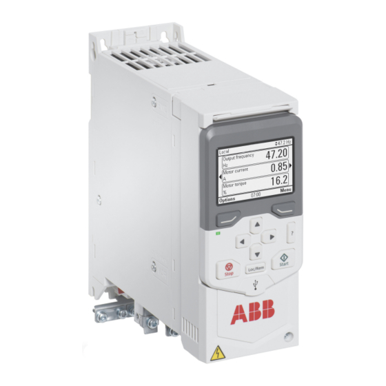
Page 33: Using The Control Panel
Using the control panel 33 Using the control panel The ACQ80 drive supports both basic and assistant control panels. For more information, see: ACX-AP-x assistant control panel’s user’s manual • (3AUA0000085685 [English]) ACS-BP-S basic control panel’s user’s manual • (3AXD50000032527... - Page 34 34 Using the control panel...
-
Page 35: Program Features
Local control vs. external control The ACQ80 drive has two main control locations, external and local. The control locations are selected with the Loc/Rem key on the control panel or in the PC tool. -
Page 36: Local Control
36 Program features External control Drive (= Programmable logic controller) Local control Embedded field- bus interface Fieldbus adapter (Fxxx) Control panel or Drive composer PC tool (optional) MOTOR Local control The control commands are given from the control panel keypad or from a PC equipped with Drive composer when the drive is in local control. -
Page 37: Operating Modes Of The Drive
Program features 37 Operating modes of the drive The drive can be operated in scalar and vector control mode. The mode is selectable for both Local and External control. See parameter 99.04 Motor control mode. Speed control mode Speed control mode is available in both local and external control. It is supported in vector motor control only. -
Page 38: Adaptive Programming
38 Program features Adaptive programming Conventionally, the user can control the operation of the drive by parameters. However, the standard parameters have a fixed set of choices or a setting range. To further customize the operation of the drive, an adaptive program can be constructed out of a set of function blocks. - Page 39 Program features 39 Inputs available to the adaptive program Input Source Motor torque 01.10 Motor torque Motor shaft power 01.17 Motor shaft power Status Enabled 1, bit 0 06.16 Drive status word Inhibited 1, bit 1 06.16 Drive status word Ready to start 1, bit 3 06.16 Drive status word...
- Page 40 40 Program features Adaptive program fault and aux code formats The format of the aux code: Bits 24-31: State number Bits 16-23: block number Bits 0-15: error code If the state number is zero but the block number has a value, the fault is related to a function block in the base program.
-
Page 41: Control Interfaces
PID purpose or to read external sensor values. With analog inputs, speed of the motor cannot be changed as motor speed control is always by internal MPPT logic of ACQ80. For more information, see section MPPT control on page 42. -
Page 42: Fieldbus Control
MPPT control program The Maximum Power Point Tracking (MPPT) control program is a built-in logic in the ACQ80 drives. This enables the drive to monitor the available DC power from the PV array and regulate the motor speed accordingly. Some of the other features of MPPT program are: •... - Page 43 Program features 43 MPPT operation with Solar power only Early Morning Evening Mid Day Max PV DC Power > Motor Power Nominal PV DC Power = Motor Power Low PV DC Power Full flow from pump Low flow from pump Note: Based on the application requirement, pump ON-OFF can be controlled by parameter mode.
-
Page 44: Solar Pump Control
44 Program features (40.96) is used as the speed limit instead of the defined maximum pump speed (79.52). PID enabled Process PID output % (40.96) 100% = Pump maximum speed (79.52) MPPT speed limit Pump maximum speed (79.52) Settings Parameter group (page 226) and 79 Solar pump control 40 Process PID set 1... -
Page 45: Flow Calculation
Program features 45 The ACQ80 drive has the below five pump control modes: 1. Auto The auto mode can be used to start and stop the pump automatically based on the values set in parameter 79.41 Start DC voltage, 79.42 PV cell min voltage, and 79.43 PV cell max... - Page 46 46 Program features 2. PQ (power/flow) curve based flow calculation In the PQ curve based flow calculation, the user can define a PQ (power/flow) performance curve that is used as the basis for the calculation or a differential pressure based flow feedback. The figure below shows the PQ performance curve of the pump for the flow calculation function.
-
Page 47: Pump Cleaning
Program features 47 The figure below shows the HQ performance curve of the pump for the flow calculation function. H [m] or H [ft] Q [m /h] or Q [gpm] Settings Parameter group (page 231) and (page 237) 80 Flow calculation 81 Sensor settings Pump cleaning ... - Page 48 48 Program features The pump cleaning sequence can have several positive direction speed steps in one cleaning sequence. Normal operation Normal operation 83.20 83.20 Time Sequence Parameter Sequence Parameter 83.26 Time to zero-speed 83.25 Time to cleaning speed 83.25 Time to cleaning speed 83.27 Cleaning on time 83.27 Cleaning on time 83.26 Time to zero-speed...
- Page 49 Program features 49 9. The drive waits until the parameter is elapsed. A new 83.28 Cleaning off time cleaning sequence starts or normal operation starts. 10. The pump starts following speed/frequency reference of the active control location. During acceleration to speed/frequency, the drive follows pump cleaning acceleration time 83.25 Time to cleaning speed.
- Page 50 50 Program features • The following triggers are used for parameter 83.12 Start pump cleaning: • Manually (With DI4, DI5 or DI6 defined by parameter 83.12 Start pump cleaning) • Through fieldbus or from control panel, with parameter 83.12 Start pump cleaning.
-
Page 51: Time Scheduled Pump Cleaning
Program features 51 Time scheduled pump cleaning Time scheduled pump cleaning allows you to clean the pump at the desired time. When the time scheduled pump cleaning is enabled and the present time is equal to the user mentioned time, the normal operation stops and the pump cleaning starts automatically. - Page 52 52 Program features Note: Fault D4B0 cannot be reset until selected DI in parameter 82.02 Dry run is low. source Drive Pump 82.47 Dry run trip 82.47 Dry run trip monitor time monitor time 82.48 Dry run reset time 21.22 Start delay Drive Pump 82.47 Dry run trip...
-
Page 53: Pump Inlet And Outlet Protection
Program features 53 Pump inlet and outlet protection The Pump inlet and outlet protection function monitors pump inlet and outlet pressure and takes the user defined actions in case the pressure is outside the normal range. The inlet and outlet minimum pressure protection function can first generate a warning when the pump pressure is below minimum pressure warning level for pressure check delay time. -
Page 54: Motor Control
54 Program features The simplified block diagram below illustrates the process PID control. 40.96 Process PID output% Setpoint 100% = 79.52 Pump maximum speed Process Filter Process actual values • • • Limitation Speed/ frequency Final reference MPPT speed/frequency reference reference Note: When PID is enabled, the PID output generated by the PID set 1 (40.96) is used as a reference limiter for speed/frequency reference generated from... -
Page 55: Motor Identification
Scalar motor control is the default motor control method. In scalar control mode, the drive is controlled with a frequency reference. ABB recommends to activate the scalar motor control mode in the following situations: • If the exact nominal motor values are not available or the drive needs to run different motors after commissioning. -
Page 56: Vector Control
56 Program features IR compensation for scalar motor control IR compensation (also known as Motor voltage voltage boost) is available only when the motor control mode is scalar. IR compensation When IR compensation is activated, the drive gives an extra voltage boost (based on the available DC Voltage) to the motor at low speeds. -
Page 57: Speed Control Performance
Program features 57 Settings • Menu - Primary settings - Motor - Control mode • Parameter (page 264) and 99.04 Motor control mode 99.13 ID run requested (page 268). Speed control performance The figure below shows the typical speed control performance. Speed control Performance Static accuracy... -
Page 58: Safety And Protections
58 Program features useful, for example, in applications where low noise is necessary but higher noise can be tolerated when the full output current is needed. Settings Parameter 97.01 Switching frequency reference 97.02 Minimum switching (page 246). frequency Safety and protections Fixed/standard protections ... - Page 59 Program features 59 temperature). After this, when power is applied to the drive, the motor is assumed to be at the estimated temperature. 2. Motor temperature is calculated using the user-adjustable motor thermal time and motor load curve. The load curve should be adjusted in case the °...
-
Page 60: Programmable Protection Functions
60 Program features See section on page 59. Insulation Thermistor relay Control board +24 V DC Motor Settings Parameter group (page 177). 35 Motor thermal protection Programmable protection functions External events (parameters 31.01…31.10) Five different event signals from the process can be connected to selectable inputs to generate trips and warnings for the driven equipment. - Page 61 Program features 61 Safe torque off detection (parameter 31.22) The drive monitors the status of the Safe torque off input, and this parameter selects which indications are given when the signals are lost. (The parameter acceleration does not affect the operation of the Safe torque off function itself). For more compensation information on the Safe torque off function, see section Implementing the Safe torque off function in the Hardware manual of the drive.
- Page 62 62 Program features Stall function (parameters 31.24…31.28) The drive monitors the stall current limit and its related parameters, and helps to prevent stalling of the motor. You can adjust the supervision limits (current, frequency and time) and choose how the drive reacts to a stall condition. Current 30.17 Maximum...
-
Page 63: Automatic Fault Resets
Program features 63 AI supervision (parameters 12.03…12.05) The parameters select how the drive reacts when an analog input signal moves out of the minimum and/or maximum limits specified for the input. This can be due to broken I/O wiring or sensor. Fan control (95.200) Fan control prevents overheating and dust accumulation in the drive. - Page 64 For more information, contact your local ABB representative. • After an emergency stop signal gets detected, the emergency stop function is activated and is not canceled even if the signal gets canceled.
-
Page 65: Diagnostics
Program features 65 Diagnostics Signal supervision Six signals can be selected to be supervised by this function. Whenever a supervised signal exceeds or falls below predefined limits, a bit in 32.01 is activated, and a warning or fault generated. Supervision status For example, if user wants to monitor DC voltage and generate a warning/fault message if it exceeds certain limit, he/she can select DC Voltage [7] in the... -
Page 66: Load Analyzer
66 Program features Menu item Description Limit status This view describes any limits currently affecting operation. If the drive is running at undesired speed, use this view to find out if any limitations are active. Active faults This view shows the currently active faults and provides instructions on how to fix and reset them. - Page 67 Program features 67 For amplitude logger 2, the user can select a signal to be sampled at 200 ms intervals, and specify a value that corresponds to 100%. The collected samples are sorted into 10 read-only parameters according to their amplitude. •...
-
Page 68: Miscellaneous
68 Program features Miscellaneous Backup and restore You can make backups of the settings manually to the assistant control panel. The assistant control panel also keeps one automatic backup. You can restore a backup to another drive, or a new drive replacing a faulty one. You can make backups and restore on the control panel or with the Drive composer PC tool. -
Page 69: User Parameter Sets
WARNING! ABB will not be liable for damages or losses caused by the failure to activate the user lock using a new pass code. See... -
Page 70: Sine Filter Support
70 Program features WARNING! Store the pass code in a safe place – even ABB cannot open the user lock if the pass code is lost. • In functionality, define the actions that you want to prevent 96.102 User lock (ABB recommends to select all the actions unless otherwise required by the application). - Page 71 Program features 71 In addition, 10% of the dead-band value is added as dead-band hysteresis positive and negative. This value is internally set in the firmware and cannot be changed. × AI Hysteresis AI dead-band value Notes: AI dead-band (12.110) is applicable for both AI1 and AI2.Example of using dead-band in AI1 (voltage mode) 12.15 AI1 unit selection = 50...
- Page 72 72 Program features When AI1 input voltage increases, up to 11 mA, the AI1 actual value (12.11) displays zero. After AI1 input voltage reaches 11 mA, the AI1 actual value displays 11 mA and continues to display the detected value up to the maximum AI1 value 20 mA (12.18).
-
Page 73: Change Panel Port To Efb Port
Program features 73 Change panel port to EFB port You can use panel port as EFB port. To change panel port to EFB port, set parameter and restart the drive. If the 58.01 Protocol enable Modbus RTU changeover of the panel part to EFB port is success, the drive does not detect control panel within 20 seconds. - Page 74 74 Program features...
-
Page 75: Control Macros
Control macros 75 Control macros Contents of this chapter This chapter describes the default control connections in ACQ80 drives. - Page 76 76 Control macros Default control connections for the ABB standard macro I/O available Reference voltage and analog inputs and outputs in base unit 1…10 kohm Signal cable shield (screen) Not configured AGND Analog input circuit common +10V Reference voltage 10 V DC...
- Page 77 Control macros 77 Output signals • Analog output AO1: Output frequency • Analog output AO2: Motor current • Relay output 1: Ready run • Relay output 2: Running • Relay output 3: Fault (-1)
- Page 78 78 Control macros...
-
Page 79: Parameters
Parameters 79 Parameters What this chapter contains The chapter describes the parameters, including actual signals, of the control program. At the end of the chapter, on page 272, there is a separate list of the parameters whose default values are different between 50 Hz and 60 Hz supply frequency settings. -
Page 80: Terms And Abbreviations
Term Definition (In the following table, shown on the same row as the parameter name) The default value of a when used in the ABB parameter standard macro. For information on other macro-specific parameter values, see chapter (page 75). Control macros... -
Page 81: Summary Of Parameter Groups
Parameters 81 Summary of parameter groups Group Contents Page Basic signals for monitoring the drive. 01 Actual values Values of references received from various sources. 03 Input references Information on warnings and faults that occurred last. 04 Warnings and faults Various run-time-type counters and measurements 05 Diagnostics related to drive maintenance. - Page 82 82 Parameters Group Contents Page Selection of data to be transferred from fieldbus 53 FBA A data out controller to drive through fieldbus adapter A. Configuration of the embedded fieldbus (EFB) 58 Embedded fieldbus interface. Start/stop enable signal source selection; 79 Solar pump control positive/negative reference enable signal source selection.
-
Page 83: Parameter Listing
Parameters 83 Parameter listing Name/Value Description Def/ FbEq16 Basic signals for monitoring the drive. 01 Actual values All parameters in this group are read-only unless otherwise noted. Note: Values of these actual signals are filtered with the filter time defined in group settings. - Page 84 84 Parameters Name/Value Description Def/ FbEq16 Shows motor current (drive output current) in 01.09 Motor current % percent of the nominal drive current. of drive nom 0.0…1000.0% Motor current. 1 = 1% Shows motor torque in percent of the nominal 01.10 Motor torque motor torque.
- Page 85 Parameters 85 Name/Value Description Def/ FbEq16 Shows amount of energy that has passed 01.20 Inverter kWh through the drive (in either direction) in full counter kilowatt-hours. Whenever the counter rolls over, is incremented. The 01.19 Inverter MWh counter minimum value is zero. 0…1000 kWh Energy in kWh.
- Page 86 86 Parameters Name/Value Description Def/ FbEq16 Shows current day energy consumption. This is 01.52 Current day kWh the energy of the last 24 hours (not necessarily continuous) the drive has been running, not the energy of a calendar day. The value is set to the value before the power cycle when the drive is again up and running.
- Page 87 Parameters 87 Name/Value Description Def/ FbEq16 Amount of energy that has passed through the 01.57 Inverter kWh drive (in either direction) in full kilowatt-hours. counter Whenever the counter rolls over, (resettable) 01.56 Inverter is incremented. The kWh counter (resettable) minimum value is zero. You can reset the value by setting it to zero.
-
Page 88: 03 Input References
88 Parameters Name/Value Description Def/ FbEq16 Shows absolute value of parameter 01.68 Abs motor shaft 01.17 Motor power shaft power. 0.00… 32767.00 Motor shaft power. 1 = 1 kW kW or hp Values of references received from various 03 Input references sources. -
Page 89: Warnings And Faults
Parameters 89 Name/Value Description Def/ FbEq16 Information on warnings and faults that 04 Warnings and faults occurred last. For explanations of individual warning and fault codes, see chapter Fault tracing. All parameters in this group are read-only unless otherwise noted. Shows code of the 1st active fault (the fault that 0x0000 04.01... -
Page 90: Diagnostics
90 Parameters Name/Value Description Def/ FbEq16 Shows the user-defined event word. This word 04.40 Event word 1 collects the status of the events (warnings, faults or pure events) selected by parameters 04.41…04.71. This parameter is read-only. Name Description User bit 0 1 = Event selected by parameter is active 04.41... - Page 91 Parameters 91 Name/Value Description Def/ FbEq16 Motor run-time counter. The counter runs when 05.02 Run-time counter the inverter modulates. 0…65535 d Motor run-time counter. 1 = 1 d Shows the pump running time in hours. The 05.03 Pump run hours pump run hours is based on the value in parameter and is...
- Page 92 92 Parameters Name/Value Description Def/ FbEq16 Diagnostic word 2. For possible causes and 0b0000 05.21 Diagnostic word remedies, see chapter Fault tracing. Name Value 0...9 Reserved Motor overtemperature Yes = Drive has tripped on fault 4981 fault External temperature 1 or4982 External temperature 2 11...15 Reserved 0b0000...0b1111 Diagnostic word 2.
- Page 93 Parameters 93 Name/Value Description Def/ FbEq16 Displays the main status word (06.11) at which 0x0000 05.85 Main status word fault occurred. For the bit list, see parameter at fault 06.11 Main status word. Name Ready to switch ON Ready run Ready ref Tripped Off 2 inactive...
-
Page 94: Control And Status Words
94 Parameters Name/Value Description Def/ FbEq16 Drive control and status words. 06 Control and status words The main control word of the drive. This 0x0000 06.01 Main control parameter shows the control signals as received word from the selected sources (such as digital inputs, the fieldbus interfaces and the application program). - Page 95 Parameters 95 Name/Value Description Def/ FbEq16 Main status word of the drive. 0x0000 06.11 Main status word For the bit descriptions see page 375. The related control word and state diagram are presented on pages respectively. This parameter is read-only. Name Ready to switch ON Ready run...
- Page 96 96 Parameters Name/Value Description Def/ FbEq16 Drive status word 1. 0b0000 06.16 Drive status word This parameter is read-only. Bit Name Description Enabled Not applicable. Inhibited 1 = Start inhibited. To start the drive, the inhibiting signal (see par. 06.18) must be removed and the start signal cycled.
- Page 97 Parameters 97 Name/Value Description Def/ FbEq16 Start inhibit status word. This word specifies the 0b0000 06.18 Start inhibit source of the inhibiting signal that is preventing status word the drive from starting. The conditions marked with an asterisk (*) only require that the start command is cycled.
- Page 98 98 Parameters Name/Value Description Def/ FbEq16 Speed control status word. 0b0000 06.19 Speed control status word This parameter is read-only. Name Description Zero speed Drive has been running below zero speed limit (30.00 rpm). Forward 1 = Drive is running in forward direction above zero speed limit.
-
Page 99: 07 System Info
Parameters 99 Name/Value Description Def/ FbEq16 Selects a binary source whose status is 06.32 MSW bit 13 False transmitted as bit 13 (User bit 2) of selection 06.11 Main status word. False True Source selection (see Other [bit] Terms and abbreviations page 80). -
Page 100: Standard Di, Ro
100 Parameters Name/Value Description Def/ FbEq16 Shows the status of the adaptive program. 07.30 Adaptive program status See section Name Description Initialized 1 = Adaptive program initialized Editing 1 = Adaptive program is being edited Edit done 1 = Editing of adaptive program finished Running 1 = Adaptive program running 4…13 Reserved... - Page 101 Parameters 101 Name/Value Description Def/ FbEq16 The electrical statuses of the digital inputs can 0b0000 10.03 DI force selection be overridden for eg. testing purposes. A bit in parameter is provided for 10.04 DI forced data each digital input, and its value is applied whenever the corresponding bit in this parameter is 1.
- Page 102 102 Parameters Name/Value Description Def/ FbEq16 Status of relay outputs RO1…RO3. 0b0000 10.21 RO status Value 1 = RO1 is energized. 1 = RO2 is energized. 1 = RO3 is energized. 3…15 Reserved 0b0000...0b1111 Status of relay outputs. 1 = 1 The signals connected to the relay outputs can 0b0000 10.22...
- Page 103 Parameters 103 Name/Value Description Def/ FbEq16 Selects a drive signal to be connected to relay 10.24 RO1 source Ready run output RO1. Not energized Output is not energized. Energized Output is energized. Ready run Bit 1 of (see page 95). 06.11 Main status word Enabled Bit 0 of...
- Page 104 104 Parameters Name/Value Description Def/ FbEq16 Reserved 30...32 Supervision 1 Bit 0 of (see page 152). 32.01 Supervision status Supervision 2 Bit 1 of (see page 152). 32.01 Supervision status Supervision 3 Bit 2 of (see page 152). 32.01 Supervision status Start delay Bit 13 of (see page 96).
- Page 105 Parameters 105 Name/Value Description Def/ FbEq16 Selects a drive signal to be connected to relay 10.27 RO2 source Running output RO2. For the available selections, see parameter 10.24 source. Defines the activation delay for relay output RO2. 0.0 s 10.28 RO2 ON delay Status of selected...
-
Page 106: Standard Dio, Fi, Fo
106 Parameters Name/Value Description Def/ FbEq16 Storage parameter for controlling the relay 0b0000 10.99 RO/DIO control outputs eg. through the embedded fieldbus word interface. To control the relay outputs (RO) of the drive, send a control word with the bit assignments shown below as Modbus I/O data. - Page 107 Parameters 107 Name/Value Description Def/ FbEq16 Shows value of frequency input 1 (via DI6DI5 11.38 Freq in 1 actual when it is used as a frequency input) before value scaling. See parameter 11.42 Freq in 1 min. This parameter is read-only. 0 …...
-
Page 108: Standard Ai
108 Parameters Name/Value Description Def/ FbEq16 Defines the value that is required to correspond 0.000 11.44 Freq in 1 at internally to the minimum input frequency scaled min defined by parameter min. See 11.42 Freq in 1 diagram at parameter 11.42 Freq in 1 min. - Page 109 Parameters 109 Name/Value Description Def/ FbEq16 Specifies the analog input limits to be 0b0000 12.04 AI supervision supervised. See parameter selection 12.03 AI supervision function. Name Description AI1 < MIN 1 = Minimum limit supervision of AI1 active. AI1 > MAX 1 = Maximum limit supervision of AI1 active.
- Page 110 110 Parameters Name/Value Description Def/ FbEq16 Shows value of analog input AI1 after scaling. See 50.000 12.12 AI1 scaled value parameters 12.19 AI1 scaled at AI1 min 12.20 AI1 scaled at AI1 max. This parameter is read-only. -32768.000… Scaled value of analog input AI1. 1 = 1 32767.000 Forced value that can be used instead of the true...
- Page 111 Parameters 111 Name/Value Description Def/ FbEq16 Defines the filter time constant for analog input 0.100 s 12.16 AI1 filter time AI1. Unfiltered signal Filtered signal O = I × (1 - e I = filter input (step) O = filter output = time T = filter time constant Note: The signal is also filtered due to the signal...
- Page 112 112 Parameters Name/Value Description Def/ FbEq16 Defines the real internal value that corresponds 0.000 12.19 AI1 scaled at AI1 to the minimum analog input AI1 value defined by parameter min. (Changing the polarity 12.17 AI1 settings of can effectively invert 12.19 12.20 the analog input.)
- Page 113 Parameters 113 Name/Value Description Def/ FbEq16 Selects the unit for readings and settings related 12.25 AI2 unit selection to analog input AI2. Note: In firmware ASCL2 and ASCL4), this setting must match the corresponding hardware setting Electrical on the drive control unit. chapter installation Hardware , section Switches in the...
- Page 114 114 Parameters Name/Value Description Def/ FbEq16 Defines the real value that corresponds to the 0.000 12.29 AI2 scaled at AI2 minimum analog input AI2 value defined by parameter min. (Changing the polarity 12.27 AI2 settings of can effectively invert 12.29 12.101 the analog input.) (12.22)
-
Page 115: Standard Ao
Parameters 115 Name/Value Description Def/ FbEq16 Configuration of standard analog outputs. 13 Standard AO The source signals of the analog outputs can be 0b0000 13.02 AO force overridden for eg. testing purposes. A forced selection value parameter is provided for each analog output, and its value is applied whenever the corresponding bit in this parameter is 1. - Page 116 116 Parameters Name/Value Description Def/ FbEq16 Temp sensor 1 The output is used to feed an excitation current excitation to the temperature sensor 1, see parameter 35.11 source. See also section Temperature 1 Motor (page 58). thermal protection Temp sensor 2 The output is used to feed an excitation current excitation to the temperature sensor 2, see parameter...
- Page 117 Parameters 117 Name/Value Description Def/ FbEq16 Selects the unit for readings and settings related 13.15 AO1 unit to analog input AO1. selection Note: In firmware ASCL2 and ASCL4), this setting must match the corresponding hardware setting Electrical on the drive control unit. See chapter installation Hardware , section Switches in the...
- Page 118 118 Parameters Name/Value Description Def/ FbEq16 Defines the real minimum value of the signal 13.17 AO1 source min (selected by parameter source) that 13.12 AO1 corresponds to the minimum required AO1 output value (defined by parameter 13.19 AO1 out at AO1 src min).
- Page 119 Parameters 119 Name/Value Description Def/ FbEq16 AO has automatic scaling. Every time the source for the AO is changed, the scaling range is changed accordingly. User given minimum and maximum values override the automatic values. 13.12 AO1 source, 13.17 AO1 source min, 13.18 AO1 source max,...
- Page 120 120 Parameters Name/Value Description Def/ FbEq16 Defines the real maximum value of the signal 50.0 13.18 AO1 source max (selected by parameter source) that 13.12 AO1 corresponds to the maximum required AO1 output value (defined by parameter 13.20 AO1 max). See parameter out at AO1 src 13.17 AO1 source...
- Page 121 Parameters 121 Name/Value Description Def/ FbEq16 Defines the real minimum value of the signal 13.27 AO2 source min (selected by parameter source) that 13.22 AO2 corresponds to the minimum required AO2 output value (defined by parameter 13.29 AO2 min). See parameter out at AO2 src 13.17 AO1 about the AO automatic scaling.
- Page 122 122 Parameters Name/Value Description Def/ FbEq16 Defines the minimum output value for analog 0.000 mA 13.29 AO2 out at AO2 output AO2. src min See also drawing at parameter 13.27 AO2 source min. 0.000 … Minimum AO2 output value. 1000 = 22.000 mA 1 mA Defines the maximum output value for analog...
-
Page 123: 21 Start/Stop Mode
Parameters 123 Name/Value Description Def/ FbEq16 Start and stop modes. 21 Start/stop mode Selects the motor start function for the vector 21.01 Start mode Automatic motor control mode, ie. when 99.04 Motor control is set to Vector. mode Notes: • The start function for the scalar motor control mode is selected by parameter 21.19 Scalar start... - Page 124 124 Parameters Name/Value Description Def/ FbEq16 Automatic Automatic start guarantees optimal motor start in most cases. It includes the flying start function (starting into a rotating motor) and the automatic restart function. The drive motor control program identifies the flux as well as the mechanical state of the motor and starts the motor instantly under all conditions.
- Page 125 Parameters 125 Name/Value Description Def/ FbEq16 Selects the way the motor is stopped when an 21.04 Emergency stop Ramp stop emergency stop command is received. mode (Off1) The source of the emergency stop signal is selected by parameter 21.05 Emergency stop source.
- Page 126 126 Parameters Name/Value Description Def/ FbEq16 Selects the source of the emergency stop signal. 21.05 Emergency stop Inactive The stop mode is selected by parameter source 21.04 (true) Emergency stop mode. 0 = Emergency stop active 1 = Normal operation Note: This parameter cannot be changed while the drive is running.
- Page 127 Parameters 127 Name/Value Description Def/ FbEq16 Automatic The drive automatically selects the correct output frequency to start a rotating motor. This is useful for flying starts: if the motor is already rotating, the drive will start smoothly at the current frequency. Note: This mode cannot be used in multimotor systems.
- Page 128 128 Parameters Name/Value Description Def/ FbEq16 Selects the forced current vector rotation mode 21.23 Smooth start Disabled at low speeds. When smooth start mode is selected, the rate of acceleration is limited by the acceleration and deceleration ramp times. If the process driven by the permanent magnet synchronous motor has high inertia, slow ramp times are recommended.
-
Page 129: 23 Speed Reference Ramp
Parameters 129 Name/Value Description Def/ FbEq16 Speed reference ramp settings (programming of 23 Speed reference ramp the acceleration and deceleration rates for the drive). Shows used speed reference (in rpm) before it 0.00 23.01 Speed ref ramp enters the ramping and shaping functions. input This parameter is read-only. - Page 130 130 Parameters Name/Value Description Def/ FbEq16 Defines the time required for the speed to 20.000 23.13 Deceleration time change from the speed defined by parameter (not from parameter 46.01 Speed scaling 30.12 speed) to zero. Maximum If the speed reference decreases slower than the set deceleration rate, the motor speed will follow the reference.
-
Page 131: Speed Reference Conditioning
Parameters 131 Name/Value Description Def/ FbEq16 Defines the time inside which the drive is 3.000 s 23.23 Emergency stop stopped if an emergency stop Off3 is activated time (i.e. the time required for the speed to change from in vector 99.09 Motor nominal speed mode/99.08 Motor nominal frequency in scalar... -
Page 132: Speed Control
The figure below shows the speed controller output after an error step when the error remains constant. Note: ABB recommends not to change the default value. This can impact the MPPT efficiency. Gain = K = Integration time = 0... - Page 133 The figure below shows the speed controller output after an error step when the error remains constant. Note: ABB recommends not to change the default value. This can impact the MPPT efficiency. Controller output Gain = K = Integration time >...
- Page 134 The figure below shows the speed controller output after an error step when the error remains constant. Note: ABB recommends not to change the default value. This can impact the MPPT efficiency. Controller output Δe...
- Page 135 25.05 Derivation filter parameter time 25.04 Speed derivation time. Note: ABB recommends not to change the default value. This can impact the MPPT efficiency. 0…10000 ms Derivation filter time constant. 1 = 1 Defines the proportional gain for the speed 10.00...
- Page 136 136 Parameters Name/Value Description Def/ FbEq16 Defines an added torque value used by the auto 10.00% 25.38 Auto tune torque tune function. This value is scaled to the motor step nominal torque. Note: The torque used by the auto tune function can also be limited by the torque limits (in parameter group Limits) and the nominal...
-
Page 137: Frequency Reference Chain
Parameters 137 Name/Value Description Def/ FbEq16 Settings for the frequency reference chain. 28 Frequency reference chain Shows used frequency reference before ramping. 0.00 28.01 Frequency ref ramp input This parameter is read-only. -500.00… Frequency reference before ramping. 10 = 1 500.00 Hz Shows final frequency reference (after selection, 0.00... -
Page 138: Limits
138 Parameters Name/Value Description Def/ FbEq16 Drive operation limits. 30 Limits Shows limit word 1. 0b0000 30.01 Limit word 1 This parameter is read-only.f Name Description Torq lim 1 = Drive torque is limited by the motor control (undervoltage control, current control, load angle control or pull-out control), or by the torque limits defined by parameters. - Page 139 Parameters 139 Name/Value Description Def/ FbEq16 Shows torque controller limitation status word. 0b0000 30.02 Torque limit status This parameter is read-only. Name Description Undervoltage *1 = Intermediate DC circuit undervoltage Overvoltage *1 = Intermediate DC circuit overvoltage Minimum *1 = Torque is being limited by 30.19 Minimum torque 1 torque Maximum...
- Page 140 140 Parameters Name/Value Description Def/ FbEq16 Defines the minimum allowed speed. -3000.00 30.11 Minimum speed WARNING! This value must not be higher than 30.12 Maximum speed. WARNING! In speed control mode only. In frequency control mode, use frequency limits (30.13 and 30.14).
- Page 141 Parameters 141 Name/Value Description Def/ FbEq16 Enables/disables temperature-based output 30.35 Thermal current Enable current limitation. limitation The limitation should only be disabled if required by the application. Disable Thermal current limitation disabled. Enable Thermal current limitation enabled. Selects a source that switches between two 30.36 Speed limit different predefined adjustable speed limit sets.
- Page 142 142 Parameters Name/Value Description Def/ FbEq16 Not selected Adjustable speed limits are disabled. (Minimum speed limit defined by 30.11 Minimum and maximum speed limit defined by speed 30.12 are active). Maximum speed Selected Adjustable speed limits are enabled. (Minimum speed limit defined by 30.37 Min speed source and maximum speed limit defined source...
-
Page 143: Fault Functions
Parameters 143 Name/Value Description Def/ FbEq16 AI1 scaled 12.12 AI1 scaled value. AI2 scaled 12.22 AI2 scaled value. Maximum speed 30.12 Maximum speed. Source selection (see Other Terms and abbreviations page 80). Configuration of external events; selection of 31 Fault functions behavior of the drive upon fault situations. - Page 144 144 Parameters Name/Value Description Def/ FbEq16 Selects the type of external event 3. 31.06 External event 3 Fault type Fault The external event generates a fault. Warning The external event generates a warning. Defines the source of external event 4. See also 31.07 External event 4 Inactive...
- Page 145 Parameters 145 Name/Value Description Def/ FbEq16 Timed function Bit 1 of (see page 34.01 Timed functions status 166). Timed function Bit 2 of (see page 34.01 Timed functions status 166). Reserved 21...23 Supervision 1 Bit 0 of (see page 152). 32.01 Supervision status Supervision 2 Bit 1 of...
- Page 146 146 Parameters Name/Value Description Def/ FbEq16 Selects which indications are given when one or 31.22 STO indication Fault/Fault both Safe torque off (STO) signals are switched run/stop off or lost. The indications also depend on whether the drive is running or stopped when this occurs.
- Page 147 Parameters 147 Name/Value Description Def/ FbEq16 Fault/Warning Inputs Indication Running Stopped Fault Warning 5091 Safe A5A0 torque off Safe torque off Faults Warning 5091 Safe A5A0 torque off FA81 Safe torque off and fault Safe torque off 1 FA81 loss Safe torque off 1 loss Faults...
- Page 148 148 Parameters Name/Value Description Def/ FbEq16 Event/Event Inputs Indication (running or stopped) Event B5A0 STO event Event and fault B5A0 STO event FA81 Safe torque off 1 loss Event and fault B5A0 STO event FA82 Safe torque off 2 loss (Normal operation) indication/No Inputs...
- Page 149 Parameters 149 Name/Value Description Def/ FbEq16 Stall speed limit in rpm. See parameter 150.00 31.26 Stall speed limit 31.24 Stall function. 0.00… Stall speed limit. 1 = 1 10000.00 rpm Stall frequency limit. See parameter 10.00 Hz 31.27 Stall frequency 31.24 Stall limit function.
- Page 150 150 Parameters Name/Value Description Def/ FbEq16 Defines, together with 15.00 Hz 31.31 Frequency trip 30.13 Minimum frequency frequency, the maximum margin 30.14 Maximum allowed frequency of the motor. If the speed (28.01 Frequency ref ramp input) exceeds the frequency limit defined by parameter 30.13 by more than the value of this parameter, 30.14...
- Page 151 Parameters 151 Name/Value Description Def/ FbEq16 Selects the warnings to be suppressed. 0000h 31.40 Disable warning messages This parameter is a 16-bit word with each bit corresponding to a warning. Whenever a bit is set to 1, the corresponding warning is suppressed. Name Description Reserved...
-
Page 152: Supervision
152 Parameters Name/Value Description Def/ FbEq16 Configuration of signal supervision functions 32 Supervision 1…6. Six values can be chosen to be monitored; a warning or fault is generated whenever predefined limits are exceeded. See also section (page 65). Signal supervision Signal supervision status word. - Page 153 Parameters 153 Name/Value Description Def/ FbEq16 Abs high Action is taken whenever absolute value of signal is above absolute value of Supervision High limit + 0.5 * hysteresis. Action is deactivated whenever absolute value of signal is below absolute value of Supervision High limit - 0.5 * hysteresis.
- Page 154 154 Parameters Name/Value Description Def/ FbEq16 Selects whether the drive generates a fault, 32.06 Supervision 1 No action warning or neither when the value monitored by action signal supervision 1 exceeds its limits. Note: This parameter does not affect the status indicated by 32.01 Supervision status.
- Page 155 Parameters 155 Name/Value Description Def/ FbEq16 Defines the lower limit for signal supervision 1. 0.00 32.09 Supervision 1 -21474836.00… Low limit. 21474836.00 Defines the upper limit for signal supervision 1. 0.00 32.10 Supervision 1 high -21474836.00… Upper limit. 21474836.00 Defines the hysteresis for the signal monitored 0.00 32.11 Supervision 1...
- Page 156 156 Parameters Name/Value Description Def/ FbEq16 Both Action is taken whenever signal is above Supervision high limit + (0.5 * hysteresis) or below Supervision low limit - (0.5*hysteresis). Action is deactivated whenever signal is in between Supervision high limit - (0.5 * hysteresis) and Supervision low limit + (0.5*hysteresis).
- Page 157 Parameters 157 Name/Value Description Def/ FbEq16 Fault if running If running, the drive trips on fault 80B0 Signal supervision Selects the signal to be monitored by signal 32.17 Supervision 2 Current supervision function 2. signal For the available selections, see parameter 32.07 Supervision 1 signal.
- Page 158 158 Parameters Name/Value Description Def/ FbEq16 Abs high Action is taken whenever absolute value of signal is above absolute value of Supervision high limit + (0.5 * hysteresis). Action is deactivated whenever absolute value of signal is below absolute value of Supervision high limit - (0.5 * hysteresis) Both Action is taken whenever signal is above...
- Page 159 Parameters 159 Name/Value Description Def/ FbEq16 Selects whether the drive generates a fault, 32.26 Supervision 3 No action warning or neither when the value monitored by action signal supervision 3 exceeds its limits. Note: This parameter does not affect the status indicated by 32.01 Supervision status.
- Page 160 160 Parameters Name/Value Description Def/ FbEq16 High Action is taken whenever signal is above Supervision high limit + (0.5 * hysteresis). Action is deactivated whenever signal is below Supervision high limit - (0.5 * hysteresis). Abs low Action is taken whenever absolute value of signal is below absolute value of Supervision low limit - (0.5 * hysteresis).
- Page 161 Parameters 161 Name/Value Description Def/ FbEq16 High rising Action is taken whenever the signal rises from a value lower than Supervision high limit - (0.5 * hysteresis) to a value which is higher than Supervision high' limit + (0.5 * hysteresis). Action is deactivated when the signal falls to a value lower than Supervision high limit - (0.5*hysteresis).
- Page 162 162 Parameters Name/Value Description Def/ FbEq16 Selects the mode of signal supervision 32.45 Supervision 5 Disabled function 5. function Determines how the monitored signal (see parameter 32.47) is compared to its lower and upper limits (32.49 respectively). The 32.40 action to be taken when the condition is fulfilled is selected by 32.46.
- Page 163 Parameters 163 Name/Value Description Def/ FbEq16 Hysteresis Action is taken whenever signal is above Supervision high limit + 0.5 * hysteresis. Action is deactivated whenever signal is below Supervision low limit - (0.5 * hysteresis). The status is unchanged when signal value is in between Supervision high limit + (0.5 * hysteresis) and 'Supervision Low' limit - (0.5 * hysteresis)
- Page 164 164 Parameters Name/Value Description Def/ FbEq16 Defines the lower limit for signal supervision 5. 0.00 32.49 Supervision 5 -21474836.00… Low limit. 21474836.00 Defines the upper limit for signal supervision 5. 0.00 32.50 Supervision 5 high -21474836.00… Upper limit. 21474836.00 Defines the hysteresis for the signal monitored 0.00 32.51 Supervision 5...
- Page 165 Parameters 165 Name/Value Description Def/ FbEq16 Both Action is taken whenever signal is above Supervision high limit + (0.5 * hysteresis) or below Supervision low limit - (0.5*hysteresis). Action is deactivated whenever signal is in between Supervision high limit - (0.5 * hysteresis) and Supervision low limit + (0.5*hysteresis).
-
Page 166: Timed Functions
166 Parameters Name/Value Description Def/ FbEq16 Fault if running Drive trips on fault if the 80B0 Signal supervision 1 motor is running. Selects the signal to be monitored by signal 32.57 Supervision 6 Zero supervision function 6. signal For the available selections, see parameter 32.07 Supervision 1 signal. - Page 167 Parameters 167 Name/Value Description Def/ FbEq16 Status of timers 1…12. 34.02 Timer status This parameter is read-only. Name Description Timer 1 1 = Active. Timer 2 1 = Active. Timer 3 1 = Active. Timer 4 1 = Active. Timer 5 1 = Active.
- Page 168 168 Parameters Name/Value Description Def/ FbEq16 Digital input DI4 (10.02 DI delayed status, bit 3). Digital input DI5 (10.02 DI delayed status, bit 4). Digital input DI6 (10.02 DI delayed status, bit 5). Source selection (see Other [bit] Terms and abbreviations page 80).
- Page 169 Parameters 169 Name/Value Description Def/ FbEq16 Defines when timer 1 is active. 0000 34.11 Timer 1 0111 1000 configuration 0000b Name Description Monday 1 = Monday is an active start day. Tuesday 1 = Tuesday is an active start day. Wednesday 1 = Wednesday is an active start day.
- Page 170 170 Parameters Name/Value Description Def/ FbEq16 Examples of how the timer configuration defines when the Timer is active are shown below. Bits of parameter 34.11 Timer 1 configuration 1 1 1 1 1 1 1 1 1 1 1 0 0 0 Example 1: Timer is active during the times of the day defined by other parameters every Weekday and every Season.
- Page 171 Parameters 171 Name/Value Description Def/ FbEq16 Defines the daily start time of timer 1. The time 00:00:00 34.12 Timer 1 start time can be changed in second steps. The timer can be started at an other time than the start time. For example, if the timer's duration is more than one day and the active session starts during the time, the timer is started at 00:00 and stopped when there is no...
- Page 172 172 Parameters Name/Value Description Def/ FbEq16 0000 0111 34.26 Timer 6 34.11 Timer 1 configuration. 1000 configuration 0000b 00:00:00 34.27 Timer 6 start time 34.12 Timer 1 start time. 00 00:00 34.28 Timer 6 duration 34.13 Timer 1 duration. 0000 0111 34.29 Timer 7 34.11 Timer 1...
- Page 173 Parameters 173 Name/Value Description Def/ FbEq16 Defines the start date of season 1 in format 01.01. 34.60 Season 1 start dd.mm, where dd is the number of the day and date mm is the number of the month. The season changes at midnight. One season can be active at a time.
- Page 174 174 Parameters Name/Value Description Def/ FbEq16 Defines the types of exceptions 1…16 as workday 0000 34.71 Exception types or holiday. 0000 Exceptions 1…3 are periods (duration can be 0000 defined) and exceptions 4…16 are days (duration 0000b is always 24 hours). Name Description Exception 1...
- Page 175 Parameters 175 Name/Value Description Def/ FbEq16 Defines the date of exception day 4. 01.01. 34.78 Exception day 4 01.01.…31.12. Start date of exception day 4. The timer started on an exception day is always stopped at 23:59:59 even if it has duration left. 01.01 34.79 Exception day 5...
- Page 176 176 Parameters Name/Value Description Def/ FbEq16 Defines which timers are connected to combined 0000 34.102 Timed function 3 timer 3. 0000 0000 34.01 Timed functions status. 0000b Defines which combined timers (that is, timers 0000 34.110 Boost time that are connected to the combined timers) are 0000 function activated with the extra time function.
-
Page 177: Motor Thermal Protection
Parameters 177 Name/Value Description Def/ FbEq16 Motor thermal protection settings such as 35 Motor thermal protection temperature measurement configuration, load curve definition and motor fan control configuration. See also section Motor thermal protection (page 58). Shows motor temperature as estimated by the 35.01 Motor estimated internal motor thermal protection model (see... - Page 178 178 Parameters Name/Value Description Def/ FbEq16 Selects the source from which measured 35.11 Temperature 1 Estimated temperature 1 is read. source temperatur Usually this source is from a sensor connected to the motor controlled by the drive, but it could be used to measure and monitor a temperature from other parts of the process as long as a suitable sensor is used as per the selection list.
- Page 179 Parameters 179 Name/Value Description Def/ FbEq16 1 × Pt100 analog Pt100 sensor connected to a standard analog input selected by parameter 35.14 Temperature 1 and an analog output. AI source The following settings are required: • Set the hardware jumper or switch related to the analog input to (voltage).
- Page 180 180 Parameters Name/Value Description Def/ FbEq16 Defines the warning limit for temperature 110 °C or 35.13 Temperature 1 supervision function 1. When measured 230 °F warning limit temperature 1 exceeds the limit, warning A491 is generated. External temperature 1 The unit is selected by parameter 96.16 Unit selection.
- Page 181 Parameters 181 Name/Value Description Def/ FbEq16 1 × Pt100 analog Pt100 sensor connected to a standard analog input selected by parameter 35.24 Temperature 2 and an analog output. AI source The following settings are required: • Set the hardware jumper or switch related to the analog input to (voltage).
- Page 182 182 Parameters Name/Value Description Def/ FbEq16 Defines the warning limit for temperature 110 °C or 35.23 Temperature 2 supervision function 2. When measured 230 °F warning limit temperature 1 exceeds the limit, warning A492 is generated. External temperature 2 The unit is selected by parameter 96.16 Unit selection.
- Page 183 Parameters 183 Name/Value Description Def/ FbEq16 Defines the motor load curve together with 100% 35.51 Motor load curve parameters 35.52 Zero speed load 35.53 Break point. The load curve is used by the motor thermal protection model to estimate the motor temperature.
- Page 184 184 Parameters Name/Value Description Def/ FbEq16 Defines the motor load curve together with 45.00 Hz 35.53 Break point parameters 35.51 Motor load curve 35.52 Zero speed load. Defines the break point frequency of the load curve ie. the point at which the motor load curve begins to decrease from the value of parameter towards the value of 35.51 Motor load curve...
- Page 185 Parameters 185 Name/Value Description Def/ FbEq16 Defines the thermal time constant for use with 256 s 35.55 Motor thermal the motor thermal protection model, defined as time const the time to reach 63% of the nominal motor temperature. See the motor manufacturer's recommendations.
-
Page 186: 36 Load Analyzer
186 Parameters Name/Value Description Def/ FbEq16 Peak value and amplitude logger settings. 36 Load analyzer See also section (page 66). Load analyzer Selects the signal to be monitored by the peak 36.01 PVL signal Output value logger. source power The signal is filtered using the filtering time specified by parameter 36.02 PVL filter time. - Page 187 Parameters 187 Name/Value Description Def/ FbEq16 Selects the signal to be monitored by amplitude 36.06 AL2 signal Motor logger 2. The signal is sampled at 200 ms source torque intervals. The results are displayed by parameters … 36.40 36.49. Each parameter represents an amplitude range, and shows what portion of the samples fall within that range.
- Page 188 188 Parameters Name/Value Description Def/ FbEq16 Shows the Motor current at the moment the peak 0.00 A 36.13 PVL current at value was recorded. peak -32768.00… Motor current at peak. 1 = 1 A 32767.00 A Shows the voltage in the intermediate DC circuit 0.00 V 36.14 PVL DC voltage...
- Page 189 Parameters 189 Name/Value Description Def/ FbEq16 Percentage of samples recorded by amplitude 0.00% 36.25 AL1 50 to 60% logger 1 that fall between 50 and 60%. 0.00…100.00% Amplitude logger 1 samples between 50 and 1 = 1% 60%. Percentage of samples recorded by amplitude 0.00% 36.26 AL1 60 to 70%...
-
Page 190: Process Pid Set 1
190 Parameters Name/Value Description Def/ FbEq16 Percentage of samples recorded by amplitude 0.00% 36.46 AL2 60 to 70% logger 2 that fall between 60 and 70%. 0.00…100.00% Amplitude logger 2 samples between 60 and 1 = 1% 70%. Percentage of samples recorded by amplitude 0.00% 36.47 AL2 70 to 80%... - Page 191 Parameters 191 Name/Value Description Def/ FbEq16 Shows value of process PID setpoint after source 40.03 Process PID selection, mathematical function limitation and setpoint actual ramping. This parameter is read-only. -200000.00... Setpoint for process PID controller. 1 = 1 200000.00 Shows process PID deviation. By default, this 40.04 Process PID value equals setpoint - feedback, but deviation...
- Page 192 192 Parameters Name/Value Description Def/ FbEq16 On when drive Process PID control is active when the drive is running running. Selects the primary source of process feedback. 40.08 Set 1 feedback 1 AI2 percent source Not selected None. AI1 scaled (see page 110).
- Page 193 Parameters 193 Name/Value Description Def/ FbEq16 Control panel Panel reference (03.01 Panel reference, see (ref saved) page 88) saved by the control system for the location where the control returns is used as the reference. Reference Ext1 reference Ext2 reference Active reference Inactive reference Ext1 ->...
- Page 194 194 Parameters Name/Value Description Def/ FbEq16 Defines the minimum time it takes for the 0.0 s 40.28 Set 1 setpoint setpoint to increase from 0% to 100%. increase time 0.0…1800.0 s Setpoint increase time. 1 = 1 Defines the minimum time it takes for the 0.0 s 40.29 Set 1 setpoint...
- Page 195 Parameters 195 Name/Value Description Def/ FbEq16 Defines the gain for the process PID controller. 1.00 40.32 Set 1 gain See parameter 40.33 Set 1 integration time. 0.01…100.00 Gain for PID controller. 100 = 1 Defines the integration time for the process PID 60.0 s 40.33 Set 1 integration...
- Page 196 196 Parameters Name/Value Description Def/ FbEq16 Defines the time constant of the 1-pole filter 0.0 s 40.35 Set 1 derivation used to smooth the derivative component of the filter time process PID controller. Unfiltered signal Filtered signal O = I × (1 - e I = filter input (step) O = filter output = time...
- Page 197 Parameters 197 Name/Value Description Def/ FbEq16 Digital input DI4 (10.02 DI delayed status, bit 3). Digital input DI5 (10.02 DI delayed status, bit 4). Digital input DI6 (10.02 DI delayed status, bit 5). Supervision 1 Bit 0 of (see page 152). 32.01 Supervision status Supervision 2 Bit 1 of...
- Page 198 198 Parameters Name/Value Description Def/ FbEq16 Defines the start limit for the sleep function. If 40.43 Set 1 sleep level the value is 0.0, set 1 sleep mode is disabled. The sleep function compares PID output (parameter actual) to the 40.01 Process PID output value of this parameter.
- Page 199 Parameters 199 Name/Value Description Def/ FbEq16 Activates (or selects a source that activates) 40.49 Set 1 tracking tracking mode. In tracking mode, the value mode selected selected by parameter 40.50 Set 1 tracking ref is substituted for the PID controller selection output.
- Page 200 200 Parameters Name/Value Description Def/ FbEq16 Selects the source of process PID set 1 activation. 40.60 Set 1 PID activation source Set 1 PID activation source is Off. Set 1 PID activation source is On. Digital input DI1 (10.02 DI delayed status, bit 0).
- Page 201 Parameters 201 Name/Value Description Def/ FbEq16 Compensated setpoint determined for the input 40.70 Compensated specified by parameter setpoint 40.71 Set 1 compensation input source. The determination of the compensated setpoint is based on the curve specified by points (x1, y1), (x2, y2) and the non-linearity of the curve specified with parameters 40.71…40.76.
- Page 202 202 Parameters Name/Value Description Def/ FbEq16 AI2 percent (see page 114). 12.102 AI2 percent value Reserved 13…14 FB A ref1 (see page 88). 03.05 FB A reference 1 FB A ref2 (see page 88). 03.06 FB A reference 2 Reserved 17…18 EFB ref1 (see page 88).
- Page 203 Parameters 203 Name/Value Description Def/ FbEq16 Selects the unit for process PID setpoint, 40.79 Set 1 units °C feedback and deviation. User text User text °C °C °F °F mbar mbar I/min I/min gal/s gal/s inHg inHg kCFM kCFM inWC inWC gal/m gal/m...
- Page 204 204 Parameters Name/Value Description Def/ FbEq16 Defines the multiplier with the result of 1.00 40.90 Set 1 feedback parameter multiplier 40.08 Set 1 feedback 1 source. -200000.00… Multiplier. 1 = 1 200000.00 Storage parameter for receiving a process 0.00 40.91 Feedback data feedback value eg.
-
Page 205: Monitoring/Scaling Settings
Parameters 205 Name/Value Description Def/ FbEq16 Speed supervision settings; actual signal 46 Monitoring/scaling settings filtering; general scaling settings. Defines the maximum speed value used to define 1500.00 46.01 Speed scaling the acceleration ramp rate and the initial speed value used to define the deceleration ramp rate (see parameter group 23 Speed reference ramp). - Page 206 For example, with a setting of 500, the fieldbus reference range of 0…20000 would correspond to a speed of 500…[99.09] rpm. Note: This parameter is effective only with the ABB Drives communication profile. 0.00 … Speed corresponding to minimum fieldbus 1 = 1 rpm 30000.00 rpm...
- Page 207 Parameters 207 Name/Value Description Def/ FbEq16 Defines the “at setpoint” limits for speed control 50.00 rpm 46.21 At speed of the drive. hysteresis When the difference between speed reference and the speed feedback is smaller than 46.21 At hysteresis, the drive is considered to be “at speed setpoint”.
-
Page 208: Panel Port Communication
208 Parameters Name/Value Description Def/ FbEq16 Defines the trigger level for “above limit” 50.00 Hz 46.32 Above frequency indication in frequency control. When actual limit frequency exceeds the limit, bit 10 of 06.17 Drive is set. status word 2 0.00… “Above limit”... -
Page 209: Fieldbus Adapter (Fba)
Parameters 209 Name/Value Description Def/ FbEq16 Selects how the drive reacts to a control panel (or 49.05 Communication Fault PC tool) communication break. loss action No action No action taken. Fault Drive trips on 7081 Control panel loss. Applies the settings of parameters 49.01…49.05. 49.06 Refresh settings Done... - Page 210 210 Parameters Name/Value Description Def/ FbEq16 Defines the time delay before the action defined 0.3 s 50.03 FBA A comm by parameter loss t out 50.02 FBA A comm loss func taken. Time count starts when the communication link fails to update the message. Notes: •...
- Page 211 Parameters 211 Name/Value Description Def/ FbEq16 Selects the type and scaling of actual value 1 50.07 FBA A actual 1 Speed or transmitted to the fieldbus network through type frequency fieldbus adapter A. The scaling of the value is defined by parameters 99.09, 99.08, 46.03 depending on which actual value type is 46.04...
- Page 212 212 Parameters Name/Value Description Def/ FbEq16 Fast Debug mode enabled. Cyclical data update is as fast as possible which increases CPU load on the drive. Shows raw (unmodified) control word sent by 0.0.0.0 50.13 FBA A control the master (PLC) to fieldbus adapter A if word debugging is enabled by parameter 50.12 FBA A...
-
Page 213: 51 Fba A Settings
Parameters 213 Name/Value Description Def/ FbEq16 Not applicable 50.18 FBA A actual value 2 Fieldbus adapter A configuration. 51 FBA A settings Shows type of the connected fieldbus adapter 51.01 FBA A type module. 0 = Module is not found or is not properly connected, or is disabled by parameter 50.01 FBA enable. - Page 214 214 Parameters Name/Value Description Def/ FbEq16 Shows drive type code in the fieldbus adapter 51.29 FBA A drive type module mapping file (stored in the memory of code the drive). This parameter is read-only. 0…65535 Drive type code stored in the mapping file. 1 = 1 Shows fieldbus adapter module mapping file 51.30...
-
Page 215: Fba A Data In
Parameters 215 Name/Value Description Def/ FbEq16 Shows application program revision of the 0x0000 51.33 FBA A appl SW adapter module in format axyz, where a = major revision number, xy = minor revision number, z = correction number or letter. Example: 190A = revision 1.90A. -
Page 216: Fba A Data Out
216 Parameters Name/Value Description Def/ FbEq16 Source selection (see Other Terms and abbreviations page 80). … … … … See parameter 52.12 FBA A data in12 52.01 FBA A data in1. None Selection of data to be transferred from fieldbus 53 FBA A data out controller to drive through fieldbus adapter A. - Page 217 Parameters 217 Name/Value Description Def/ FbEq16 Shows protocol ID and revision. 58.02 Protocol ID This parameter is read-only. Protocol ID and revision. 1 = 1 Defines the node address of the drive on the 58.03 Node address fieldbus link. Values 1…247 are allowable. Two devices with the same address are not allowed on-line.
- Page 218 218 Parameters Name/Value Description Def/ FbEq16 Refresh settings Refreshes settings (parameters 58.01…58.05, 58.14…58.17, 58.25, 58.28…58.34) and takes changed EFB configuration settings in use. Reverts automatically to Enabled. Silent mode Activates silent mode (no messages are transmitted). Silent mode can be terminated by activating the selection of this parameter.
- Page 219 Parameters 219 Name/Value Description Def/ FbEq16 Shows a count of valid packets addressed to the 58.08 Received drive. During normal operation, this number packets increases constantly. Can be reset from the control panel by keeping Reset down for over 3 seconds. 0…4294967295 Number of received packets addressed to the 1 = 1...
- Page 220 220 Parameters Name/Value Description Def/ FbEq16 Fault The drive monitors communication loss when start/stop is expected from the EFB on the currently active control location. Drive trips on if control in the currently 6681 EFB comm loss active control location is expected from the EFB or reference is coming from the EFB, and the communication is lost.
- Page 221 58.06 Communication control (Refresh settings). ABB Drives ABB Drives control profile (with a 16-bit control word) DCU Profile DCU control profile (with a 16 or 32-bit control word) Selects the type and scaling of reference 1 58.26...
- Page 222 222 Parameters Name/Value Description Def/ FbEq16 Torque Torque reference. The scaling is defined by parameter 46.03 Torque scaling. Speed Speed reference. The scaling is defined by parameter 46.01 Speed scaling. Frequency Frequency reference. The scaling is defined by parameter 46.02 Frequency scaling.
- Page 223 Parameters 223 Name/Value Description Def/ FbEq16 Not applicable 58.32 EFB act2 transparent source Defines the mapping between parameters and 58.33 Addressing mode Mode 0 holding registers in the 400101…465535 Modbus register range. Changes to this parameter take effect after the control unit is rebooted or the new settings validated by parameter 58.06 Communication...
- Page 224 Ref1 16bit Reference REF1 (16 bits) Ref2 16bit Reference REF2 (16 bits) SW 16bit profile: 16-bit ABB drives status word; ABB Drives Profile: lower 16 bits of the DCU status word Act1 16bit Actual value ACT1 (16 bits) Act2 16bit...
- Page 225 Parameters 225 Name/Value Description Def/ FbEq16 Feedback data Parameter 40.91 Feedback data storage. storage Setpoint data Parameter 40.92 Setpoint data storage. storage Source selection (see Other Terms and abbreviations page 80). Defines the address in the drive which the 58.102 Data I/O 2 Ref1 16bit Modbus master accesses when it reads from or writes to register address 400002.
-
Page 226: Solar Pump Control
226 Parameters Name/Value Description Def/ FbEq16 Start/stop enable signal source selection; 79 Solar pump control positive/negative reference enable signal source selection. See also chapter Solar pump control (page 44). Solar status word 1. 0b0000 79.01 Solar status word1 This parameter is read-only. Name Description Rdy ON... - Page 227 Parameters 227 Name/Value Description Def/ FbEq16 Solar status word 2. 0b0000 79.02 Solar status word2 This parameter is read-only. Name Description Ext fault2 1= External fault 2. AI1 Supervision 1= Analog input AI1 signal is below the limit Reserved Panel loss 1 = Control panel selected as active control location for drive has stopped communicating.
- Page 228 228 Parameters Name/Value Description Def/ FbEq16 Manual In1P The sources of the start and stop commands are Start; In2 Stop selected by parameters 79.11 Manual input source 2. The DI selected 79.12 Manual input source by 79.12 Manual input source 2 should be always On before you start the drive with pulse start command and during running condition.
- Page 229 Parameters 229 Name/Value Description Def/ FbEq16 Selects the source for the tank level operation 79.15 Enable tank level Disable enable signal. operation 0 = Disabled. 1 = Enabled. Notes: • Works only with Manual In 1 Start; stop operating mode. See parameter 79.10 Operating mode.
- Page 230 230 Parameters Name/Value Description Def/ FbEq16 Selects the interlock source for pump start and 79.39 Pump start Enable stop. When the interlock is disabled, pump interlock cannot be started in any operating modes and tank level sensor operation cannot function. Disable 0 = Pump start interlock is disabled.
-
Page 231: 80 Flow Calculation
Parameters 231 Name/Value Description Def/ FbEq16 Defines the minimum motor speed. At any value 79.51 Pump minimum below this speed, the MPPT function is not active speed and drive stops functioning. The drive auto restarts after the time defined in 79.61 Fault reset time. - Page 232 232 Parameters Name/Value Description Def/ FbEq16 Shows cumulative calculated flow. 0.00 80.03 Total flow 0.00... Total flow. 1 = 1 21474836.00 m Shows the ratio of pump flow rate and power 0.00 80.04 Specific energy input. 0.00...32767.95 Specific energy of the pump. 1 = 1 /kWh /kWh...
- Page 233 Parameters 233 Name/Value Description Def/ FbEq16 AI1 percent (see page 114). 12.101 AI1 percent value AI2 percent (see page 114). 12.102 AI2 percent value Feedback data (see page 204). 40.91 Feedback data storage storage Source selection (see Other Terms and abbreviations page 80).
- Page 234 234 Parameters Name/Value Description Def/ FbEq16 HQ curve The HQ curve is used for flow calculation. You can configure pressure sensor settings with parameter group 81 Sensor settings. The figure below shows the HQ performance curve of the pump for the flow calculation function.
- Page 235 Parameters 235 Name/Value Description Def/ FbEq16 Defines the nominal maximum flow of the 1000.00 80.15 Maximum flow system. This value is used to calculate the actual flow percentage value so that the value 100% for corresponds to the value of this parameter. 80.02 -200000.00…...
- Page 236 236 Parameters Name/Value Description Def/ FbEq16 Defines the density of the fluid to be pumped for 1000.00 80.28 Density the flow calculation function. kg/m 0.00... Fluid density. 1 = 1 kg/m 32767.00 kg/m Resets the measured flow data of actual signals 80.29 Total flow reset to zero in the parameters...
-
Page 237: 81 Sensor Settings
Parameters 237 Name/Value Description Def/ FbEq16 Defines the flow rate at point 1 on the PQ 0.00 80.60 Q value Q1 performance curve. See section (page45). Flow calculation 0.00... Flow rate at point 1 of the PQ curve. 1 = 1 200000.00 Defines the flow rate at point 2 on the PQ 0.00... - Page 238 238 Parameters Name/Value Description Def/ FbEq16 Source selection (see Other Terms and abbreviations page 80). Selects the primary source used for pump outlet 81.11 Outlet pressure pressure measurement. source selected Not selected None. AI1 scaled Parameter 12.12 AI1 scaled value. AI2 scaled Parameter 12.22 AI2 scaled...
-
Page 239: 82 Pump Protections
Parameters 239 Name/Value Description Def/ FbEq16 Ib/gal Pounds per US gallon. Settings for pup dry run protection. 82 Pump protections See section (page 51). Dry run protection Selects the source for dry run protection. 82.02 Dry run source Min load current Not selected 0 (always off). - Page 240 240 Parameters Name/Value Description Def/ FbEq16 Warning/Fault Outlet minimum pressure protection function first generates a warning when the pressure is below the level defined with parameter 82.31 for a time Outlet minimum pressure warning level set in parameter 82.45 Pressure check delay.
- Page 241 Parameters 241 Name/Value Description Def/ FbEq16 Defines the level at which drive should generate 0.00 bar 82.37 Outlet maximum the outlet maximum pressure warning. pressure warning level 0.00... Outlet maximum pressure warning level. 1 = 1 bar 32767.00 bar Defines the level at which drive should generate 0.00 bar 82.38 Outlet maximum...
-
Page 242: 83 Pump Cleaning
242 Parameters Name/Value Description Def/ FbEq16 Defines the delay time at which the pressure 3.00 s 82.45 Pressure check supervisions are inactive. delay You can adjust check delay for a system in which the pressure does not increase immediately after starting the motor. - Page 243 Parameters 243 Name/Value Description Def/ FbEq16 Displays the cleaning count. Cleaning count 83.03 Total cleaning increments by one, when the sequence of count cleaning cycles are completed. For example, if 83.16 Cycles in cleaning program set as 3, the pump cleaning completes after three cycles of reverse and forward motions of the pump and the cleaning count changes to 1.
- Page 244 244 Parameters Name/Value Description Def/ FbEq16 Enables/disables the pump cleaning. 83.12 Start pump Not active cleaning Not active Pump cleaning is not active. Start cleaning Starts pump cleaning immediately. Starts pump cleaning when DI4 goes high. Starts pump cleaning when DI5 goes high. Starts pump cleaning when DI6 goes high.
- Page 245 Parameters 245 Name/Value Description Def/ FbEq16 Defines the cleaning off time when the drive 5.000 83.28 Cleaning off time stays at zero speed between positive and negative pulses and after one cleaning cycle before starting a new cleaning cycle. 0.000... Time 1 = 1s 1000.000 s...
-
Page 246: 95 Hw Configuration
246 Parameters Name/Value Description Def/ FbEq16 Various hardware-related settings. 95 HW configuration Selects the supply voltage range. This parameter 95.01 Supply voltage Automatic / is used by the drive to determine the nominal voltage of the supply network. The parameter selected also affects the current ratings and the DC voltage control functions of the drive. - Page 247 Refer to the hardware manual of the drive. Name Information Reserved ABB Sine filter 1 = An ABB sine filter is connected to the output of the drive. 2…15 Reserved 0b0000…0b111 Hardware options configuration word. 1 = 1...
-
Page 248: 96 System
248 Parameters Name/Value Description Def/ FbEq16 Enables the use of the motor disconnect switch. 95.26 Motor disconnect Disable When enabled, the drive does not trip to a fault switch when it detects the disconnection but remains operational and returns to normal operation after a reconnection. - Page 249 Note: You must change the default user pass code to maintain a high level of cybersecurity. Store the code in a safe place – the protection cannot be disabled even by ABB if the code is lost. See also section (page 69).
- Page 250 After a selection is made, the parameter reverts automatically to Done. Done Macro selection complete; normal operation. ABB standard Factory macro (see page 76). For scalar motor control. PID macro (see page 77). Shows which control macro is currently selected.
- Page 251 Parameters 251 Name/Value Description Def/ FbEq16 Restore Restores all editable parameter values to default defaults values, except • motor data and ID run results • I/O extension module settings • end user texts, such as customized warnings and faults, and the drive name •...
- Page 252 252 Parameters Name/Value Description Def/ FbEq16 Saves the valid parameter values to the 96.07 Parameter save Done permanent memory on the drive control unit to manually ensure that operation can continue after cycling the power. The new parameter values are saved automatically when changed from a PC tool or control panel, after the drive is powered on for more than 60 seconds.
- Page 253 Parameters 253 Name/Value Description Def/ FbEq16 User3 IO active User set 3 has been selected by parameters 96.12 User set I/O mode in1 96.13 User set I/O mode in2. User4 IO active User set 4 has been selected by parameters 96.12 User set I/O mode in1 96.13 User set I/O mode...
- Page 254 254 Parameters Name/Value Description Def/ FbEq16 When parameter is set to 96.12 User set I/O 96.11 User set save/load mode, selects the user parameter set mode in1 User set I/O selected together with parameter 96.13 User set I/O mode as follows: Status of Status of User...
- Page 255 Parameters 255 Name/Value Description Def/ FbEq16 Selects the unit of parameters indicating power, 0b0000 96.16 Unit selection temperature and torque. Name Information Power unit 0 = kW 1 = hp Reserved Temperature unit 0 = °C 1 = °F Reserved Torque unit 0 = Nm (N·m) 1 = lbft (lb·ft)
- Page 256 96.79 Legacy control only EFB supports legacy profiles. profile selected Not selected EFB: Control profile selected with 58.25 Control used. profile Legacy DCU profile used. ABB drives ABB drives profile used. ABB drives Legacy ABB drives limited profile used. limited...
- Page 257 Parameters 257 Name/Value Description Def/ FbEq16 Visible when user lock is open 10000000 96.100 Change user pass code To change the current user pass code, enter a new code into this parameter as well as 96.101 code. A warning will be active Confirm user pass until the new pass code is confirmed.
- Page 258 Note that the changes made take effect only when the user lock is closed. See parameter 96.02 Pass code. Note: ABB recommends to select all the actions and functionalities unless otherwise required by the application. Name Information...
-
Page 259: 97 Motor Control
See section reference Switching frequency page 57. Higher switching frequency results in lower acoustic noise. Note: If you have a multimotor system, contact your local ABB representative. 2 kHz 2 kHz 4 kHz 4 kHz 8 kHz 8 kHz... - Page 260 260 Parameters Name/Value Description Def/ FbEq16 Defines the relative output voltage boost at zero 3.50% 97.13 IR compensation speed (IR compensation). The function is useful in applications with a high break-away torque where vector control cannot be applied. Relative output voltage. IR compensation set to 15%.
- Page 261 Parameters 261 Name/Value Description Def/ FbEq16 Enabled max DC bus voltage stabilizer enabled, maximum stabilization. Sets gain for slip compensation (in %) while drive 97.49 Slip gain for is operating in scalar control mode. scalar • A squirrel-cage motor slips under load. Increasing the frequency as the motor torque increases compensates for the slip.
-
Page 262: 98 User Motor Parameters
262 Parameters Name/Value Description Def/ FbEq16 Motor values supplied by the user that are used 98 User motor parameters in the motor model. These parameters are useful for non-standard motors, or to just get more accurate motor control of the motor on site. A better motor model always improves the shaft performance. - Page 263 Parameters 263 Name/Value Description Def/ FbEq16 Defines the direct axis (synchronous) inductance. 0.00000 98.06 Ld user p.u. Note: This parameter is valid only for permanent magnet motors. 0.00000 … Direct axis inductance in per unit. 10.00000 p.u Defines the quadrature axis (synchronous) 0.00000 98.07 Lq user...
-
Page 264: 99 Motor Data
264 Parameters Name/Value Description Def/ FbEq16 Motor configuration settings. 99 Motor data Selects the motor type. 99.03 Motor type Asynchron ous motor Note: This parameter cannot be changed while the drive is running. Asynchronous Standard squirrel cage AC induction motor motor (asynchronous induction motor). - Page 265 Parameters 265 Name/Value Description Def/ FbEq16 Scalar Scalar control. Suitable for most applications, if top performance is not required. Motor identification run is not required. Note: Scalar control must be used in the following situations: • with multimotor systems 1) if the load is not equally shared between the motors, 2) if the motors are of different sizes, or 3) if the motors are going to be changed after the...
- Page 266 266 Parameters Name/Value Description Def/ FbEq16 Defines the nominal motor voltage supplied to 400.0 V 99.07 Motor nominal the motor. This setting must match the value on voltage the rating plate of the motor. Notes: • With permanent magnet motors, the nominal voltage is the BackEMF voltage at nominal speed of the motor.
- Page 267 Parameters 267 Name/Value Description Def/ FbEq16 Defines the cosphi of the motor for a more 0.00 99.11 Motor nominal accurate motor model. The value is not cos ϴ obligatory, but is useful with an asynchronous motor, especially when performing a standstill identification run.
- Page 268 268 Parameters Name/Value Description Def/ FbEq16 Selects the type of the motor identification 99.13 ID run requested None routine (ID run) performed at the next start of the drive. During the ID run, the drive will identify the characteristics of the motor for optimum motor control.
- Page 269 Parameters 269 Name/Value Description Def/ FbEq16 Normal Normal ID run. Guarantees good control accuracy for all cases. The ID run takes about 90 seconds. This mode should be selected whenever it is possible. Notes: • If the load torque will be higher than 20% of motor nominal torque, or if the machinery is not able to withstand the nominal torque transient during the ID run, then the driven...
- Page 270 270 Parameters Name/Value Description Def/ FbEq16 Standstill Standstill ID run. The motor is injected with DC current. With an AC induction (asynchronous) motor, the motor shaft is not rotated. With a permanent magnet motor, the shaft can rotate up to half a revolution. Note: This mode should be selected only if the ID run is not Normal,...
- Page 271 Parameters 271 Name/Value Description Def/ FbEq16 Standstill ID run. Standstill Advanced ID run. Advanced Adaptive ID run. Adaptive Calculated number of pole pairs in the motor. 99.15 Motor polepairs calculated 0…1000 Number of pole pairs. 1 = 1 Switches the rotation direction of motor. This 99.16 Motor phase U V W...
-
Page 272: Differences In The Default Values Between 50 Hz And 60 Hz Supply Frequency Settings
272 Parameters Differences in the default values between 50 Hz and 60 Hz supply frequency settings Parameter bit 0 changes the 95.20 HW options word 1 Supply frequency 60 Hz drive parameter default values according to the supply frequency, 50 Hz or 60 Hz. -
Page 273: Additional Parameter Data
Additional parameter data 273 Additional parameter data What this chapter contains This chapter lists the parameters with some additional data such as their ranges and 32-bit fieldbus scaling. For parameter descriptions, see chapter (page 79). Parameters Terms and abbreviations Term Definition Signal measured or calculated by the drive. -
Page 274: Fieldbus Addresses
274 Additional parameter data Term Definition Packed Boolean (bit list). Real number. Real Parameter type. See Type Analog src, Binary src, List, PB, Real. Fieldbus addresses User’s manual Refer to the of the fieldbus adapter. -
Page 275: Parameter Groups 1
Additional parameter data 275 Parameter groups 1…9 Name Type Range Unit FbEq32 01 Actual values 01.01 Motor speed used -30000.00…30000.00 100 = 1 rpm Real 01.02 Motor speed estimated -30000.00…30000.00 100 = 1 rpm Real 01.03 Motor speed % -1000.00…1000.00 100 = 1% Real 01.06... - Page 276 276 Additional parameter data Name Type Range Unit FbEq32 01.62 Abs motor speed % 0.00…1000.00% 100 = 1% Real 01.63 Abs output frequency 0.00…500.00 Hz 100 = 1 Hz Real 01.64 Abs motor torque 0.0…1600.0 10 = 1% Real 01.65 Abs output power 0.00…32767.00 100 = 1 kW...
- Page 277 Additional parameter data 277 Name Type Range Unit FbEq32 05 Diagnostics 0…65535 1 = 1 05.01 On-time counter Real 0…65535 1 = 1 05.02 Run-time counter Real 05.03 Pump run hours 0.0...429496729.5 1 = 1 Real 0…65535 1 = 1 05.04 Fan on-time counter Real...
- Page 278 278 Additional parameter data Name Type Range Unit FbEq32 06.31 MSW bit 12 selection 0...2 1 = 1 Binary 06.32 MSW bit 13 selection 0...1 1 = 1 Binary 06.33 MSW bit 14 selection 0...1 1 = 1 Binary 07 System info 07.03 Drive rating id 1 = 1...
-
Page 279: Parameter Groups 10
Additional parameter data 279 Parameter groups 10…99 Name Type Range Unit FbEq32 10 Standard DI, RO 10.02 DI delayed status 0b0000...0b1111 1 = 1 10.03 DI force selection 0b0000...0b1111 1 = 1 10.04 DI forced data 0b0000...0b1111 1 = 1 10.21 RO status 0b0000...0b1111... - Page 280 280 Additional parameter data Name Type Range Unit FbEq32 12.04 AI supervision selection 0b000...0b1111 1 = 1 12.05 AI supervision force 0b000...0b1111 1 = 1 12.11 AI1 actual value 0.000…11.000 V 1000 = Real 1 unit 12.12 AI1 scaled value 1000 = 1 Real 32768.000…32767.000...
- Page 281 Additional parameter data 281 Name Type Range Unit FbEq32 13.12 AO1 source 1 = 1 Analog 13.13 AO1 forced value 0.000…22.000 or 1000 = Real 0.000…11000 V 1 mA 13.15 AO1 unit selection 2, 10 1 = 1 List 13.16 AO1 filter time 0.000…30.000 1000 = 1 s...
- Page 282 282 Additional parameter data Name Type Range Unit FbEq32 23 Speed reference ramp 23.01 Speed ref ramp input -30000.00…30000.00 100 = Real 1 rpm 23.02 Speed ref ramp output -30000.00…30000.00 100 = Real 1 rpm 23.12 Acceleration time 1 0.000…1800.000 1000 = 1 s Real 23.13...
- Page 283 Additional parameter data 283 Name Type Range Unit FbEq32 28 Frequency reference chain 28.01 Frequency ref ramp -500.00…500.00 100 = 1 Hz Real input 28.02 Frequency ref ramp -500.00…500.00 100 = 1 Hz Real output 28.72 Freq acceleration time 1 0.000…1800.000 1000 = 1 s Real...
- Page 284 284 Additional parameter data Name Type Range Unit FbEq32 31.07 External event 4 source 1 = 1 Binary 31.08 External event 4 type 0…1 1 = 1 List 31.09 External event 5 source 1 = 1 Binary 31.10 External event 5 type 0…1 1 = 1 List...
- Page 285 Additional parameter data 285 Name Type Range Unit FbEq32 32.17 Supervision 2 signal 1 = 1 Analog 32.18 Supervision 2 filter time 0.000…30.000 1000 = 1 s Real 32.19 Supervision 2 low -21474836.00… 100 = 1 Real 21474836.00 32.20 Supervision 2 high -21474836.00…...
- Page 286 286 Additional parameter data Name Type Range Unit FbEq32 32.57 Supervision 6 signal 1 = 1 Analog 32.58 Supervision 6 filter time 0.000…30.000 1000 = 1 s Real 32.59 Supervision 6 low -21474836.00… 100 = 1 Real 21474836.00 32.60 Supervision 6 high -21474836.00…...
- Page 287 Additional parameter data 287 Name Type Range Unit FbEq32 34.30 Timer 7 start time Time 00:00:00…23:59:59 1 = 1 s 34.31 Timer 7 duration Durati 00 00:00…07 00:00 1 = 1 min 34.32 Timer 8 configuration 0000h…FFFFh 1 = 1 34.33 Timer 8 start time Time...
- Page 288 288 Additional parameter data Name Type Range Unit FbEq32 34.81 Exception day 7 Date 01.01…31.12 1 = 1 d 34.82 Exception day 8 Date 01.01…31.12 1 = 1 d 34.83 Exception day 9 Date 01.01…31.12 1 = 1 d 34.84 Exception day 10 Date 01.01…31.12...
- Page 289 Additional parameter data 289 Name Type Range Unit FbEq32 35.50 Motor ambient -60…100 °C or °C, °F 1 = 1 ° Real temperature -76 … 212 °F 35.51 Motor load curve 50…150 1 = 1% Real 35.52 Zero speed load 50…150 1 = 1% Real...
- Page 290 290 Additional parameter data Name Type Range Unit FbEq32 36.41 AL2 10 to 20% 0.00…100.00 100 = 1% Real 36.42 AL2 20 to 30% 0.00…100.00 100 = 1% Real 36.43 AL2 30 to 40% 0.00…100.00 100 = 1% Real 36.44 AL2 40 to 50% 0.00…100.00 100 = 1%...
- Page 291 Additional parameter data 291 Name Type Range Unit FbEq32 40.26 Set 1 setpoint min -200000.00... 100 = 1 Real 200000.00 40.27 Set 1 setpoint max -200000.00... 100 = 1 Real 200000.00 40.28 Set 1 setpoint increase 0.0…1800.0 10 = 1 s Real time 40.29...
- Page 292 292 Additional parameter data Name Type Range Unit FbEq32 40.59 Set 1 decrease 0...1 1 = 1 Binary prevention 40.60 Set 1 PID activation 1 = 1 List source 40.61 Setpoint scaling actual -200000.00... 100 = 1 Real 200000.00 40.62 PID internal setpoint -200000.00...
- Page 293 Additional parameter data 293 Name Type Range Unit FbEq32 46.03 Torque scaling 0.1…1000.0 10 = 1% Real 46.04 Power scaling 0.10…30000.00 kW or kW or 10 = 1 unit Real 0.10…40200.00 hp 46.05 Current scaling 0…30000 1 = 1 A Real 46.06 Speed ref zero scaling...
- Page 294 294 Additional parameter data Name Type Range Unit FbEq32 50.09 FBA A SW transparent 1 = 1 Analog source 50.10 FBA A act1 transparent 1 = 1 Analog source 50.11 FBA A act2 transparent Not applicable Analog source 50.12 FBA A debug mode 0…1 1 = 1 List...
- Page 295 Additional parameter data 295 Name Type Range Unit FbEq32 58.04 Baud rate 0…7 1 = 1 List 58.05 Parity 0…3 1 = 1 List 58.06 Communication control 0…2 1 = 1 List 58.07 Communication 0000h…FFFFh 1 = 1 diagnostics 58.08 Received packets 0…4294967295 1 = 1...
- Page 296 296 Additional parameter data Name Type Range Unit FbEq32 58.106 Data I/O 6 1 = 1 Analog 58.107 Data I/O 7 1 = 1 Analog … … … … … 58.114 Data I/O 14 1 = 1 Analog 79 Solar pump control 79.01 Solar status word1 0b0000...0b1111...
- Page 297 Additional parameter data 297 Name Type Range Unit FbEq32 80.11 Flow feedback 1 source 0…3, 8…10 1 = 1 List 80.12 Flow feedback 2 source 0…3, 8…10 1 = 1 List 80.13 Flow function 0…1, 8…9, 100…101 1 = 1 List 80.14 Flow calc gain...
- Page 298 298 Additional parameter data Name Type Range Unit FbEq32 81.11 Outlet pressure source 1 = 1 Analog 81.12 Sensors height 0.00...32767.00 100 = 1 Real difference 81.20 Pressure unit 0…3 1 = 1 List 81.21 Flow unit 0...1 1 = 1 List 81.22 Length unit...
- Page 299 Additional parameter data 299 Name Type Range Unit FbEq32 83.12 Start pump cleaning 0...4 1 = 1 Binary 83.15 Fixed time interval Time 00:00:00…45:12:15 1 = 1 83.16 Cycles in cleaning 1...65535 1 = 1 Real program 83.20 Cleaning speed step 0...3000 1 = 1 Real...
- Page 300 300 Additional parameter data Name Type Range Unit FbEq32 96.07 Parameter save 0, 1 1 = 1 List manually 96.08 Control board boot 0, 1 1 = 1 List 96.10 User set status 0...11 1 = 1 List 96.11 User set save/load 0...5, 18...21 1 = 1 List...
- Page 301 Additional parameter data 301 Name Type Range Unit FbEq32 98 User motor parameters 98.01 User motor model mode 0…1 1 = 1 List 98.02 Rs user 0.0000…0.50000 p.u. 100000 = Real 1 p.u. 98.03 Rr user 0.0000…0.50000 p.u. 100000 = Real 1 p.u.
- Page 302 302 Additional parameter data Name Type Range Unit FbEq32 99.14 Last ID run performed 1 = 1 List 99.15 Motor polepairs 0…1000 1 = 1 Real calculated 99.16 Motor phase order 0…1 1 = 1 List...
-
Page 303: Fault Tracing
The chapter lists the warning and fault messages including possible causes and corrective actions. The causes of most warnings and faults can be identified and corrected using the information in this chapter. If not, contact an ABB service representative. If you have a possibility to use the Drive composer PC tool, send the Support package created by the Drive composer to the ABB service representative. -
Page 304: Pure Events
304 Fault tracing Warnings do not need to be reset; they stop showing when the cause of the warning ceases. Warnings do not latch and the drive will continue to operate the motor. Faults latch inside the drive and cause the drive to trip, and the motor stops. After the cause of a fault has been removed, the fault can be reset from a selectable source (parameter selection) such as the control... - Page 305 Fault tracing 305 For active faults and warnings, see • Menu - Diagnostics Active faults • Menu - Diagnostics Active warnings • parameters in group (page 89). 04 Warnings and faults For previously occurred faults, see • Menu - Diagnostics Fault history •...
-
Page 306: Warning Messages
306 Fault tracing Warning messages Note: The list also contains events that only appear in the Event log. Warning / Aux. code aux code visible Code Cause What to do only on assistant (hex) control panel and drive composer 64FF Fault reset A fault has been reset Event. - Page 307 If an earth fault is found, fix or change the motor cable and/or motor. If no earth fault can be detected, contact your local ABB representative. A2B4 Short circuit Short-circuit in motor Check motor and motor cable cable(s) or motor.
- Page 308 Check the supply voltage. the drive is stopped). If the problem persists, contact A3AA DC not charged The voltage of the your local ABB representative. intermediate DC circuit has not yet risen to operating level. A490 Incorrect Sensor type mismatch...
- Page 309 Fault tracing 309 Warning / Aux. code aux code visible Code Cause What to do only on assistant (hex) control panel and drive composer A4A1 IGBT Estimated drive IGBT Check ambient conditions. overtemperature temperature is excessive. Check air flow and fan operation.
- Page 310 310 Fault tracing Warning / Aux. code aux code visible Code Cause What to do only on assistant (hex) control panel and drive composer A580 Communication errors Check connections between communication between drive control drive control unit and power unit unit and power unit.
- Page 311 Code Cause What to do only on assistant (hex) control panel and drive composer A5EA Measurement Problem with internal Contact your local ABB circuit temperature representative. temperature measurement of the drive. A5EB PU board Power unit power supply Contact your local ABB powerfail failure.
- Page 312 312 Fault tracing Warning / Aux. code aux code visible Code Cause What to do only on assistant (hex) control panel and drive composer 1 Slip frequency is too Check the settings of the motor small. configuration parameters in groups 98 and 99. 2 Synchronous and Check that the drive is sized nominal speeds differ...
- Page 313 If not, check the following: • All switches between drive and motor are closed. • All cables between drive and motor are connected and secured. If no issue was detected and drive output was actually connected to motor, contact ABB.
- Page 314 314 Fault tracing Warning / Aux. code aux code visible Code Cause What to do only on assistant (hex) control panel and drive composer A7AB Built in/Extension The I/O built Make sure that the I/O built I/O configuration in/extension module is in/extension module is failure not connected to the...
- Page 315 Fault tracing 315 Warning / Aux. code aux code visible Code Cause What to do only on assistant (hex) control panel and drive composer 0002 Relay output 2 Change the control board or stop using relay output 2. 0003 Relay output 3 Change the control board or stop using relay output 3.
- Page 316 316 Fault tracing Warning / Aux. code aux code visible Code Cause What to do only on assistant (hex) control panel and drive composer A8B1 Signal supervision Warning generated by Check the source of the warning the signal supervision (parameter 32.17 Supervision 2 function 2.
- Page 317 Fault tracing 317 Warning / Aux. code aux code visible Code Cause What to do only on assistant (hex) control panel and drive composer A981 External warning 1 Fault in external device 1. Check the external device. (Editable message Check setting of parameter text) 31.01 External event 1 source.
- Page 318 318 Fault tracing Warning / Aux. code aux code visible Code Cause What to do only on assistant (hex) control panel and drive composer AFE1 Emergency stop Emergency stop (mode Check that it is safe to continue (off2) selection off2) command. operation.
- Page 319 Fault tracing 319 Warning / Aux. code aux code visible Code Cause What to do only on assistant (hex) control panel and drive composer 0005 Motor could not Decrease the torque step decelerate with full (parameter 25.38) or the speed autotune torque.
- Page 320 320 Fault tracing Warning / Aux. code aux code visible Code Cause What to do only on assistant (hex) control panel and drive composer D50C Maximum flow Actual flow is exceeded Check the system for leakages. protection the defined warning Check flow protection settings level.
- Page 321 Fault tracing 321 Warning / Aux. code aux code visible Code Cause What to do only on assistant (hex) control panel and drive composer D5B0 Pump min speed This alarm occurs when Check the pump minimum the start command is speed set in 79.51 Pump provided and the actual...
-
Page 322: Fault Messages
ID. the drive. If the fault reappears, cycle the power to the drive. You may have to be repeat this. If the fault persists, contact your local ABB representative. 2281 Calibration Measured offset of Try performing the current output phase current calibration again. - Page 323 Try running the motor in scalar control mode if allowed. (See parameter 99.04 Motor control mode.) If no earth fault can be detected, contact your local ABB representative.
- Page 324 2392 BU earth leakage Total earth leakage of Check there are no power factor inverter modules is correction capacitors or surge excessive. absorbers in motor cable. Measure insulation resistances of motor cables and motor. Contact your local ABB representative.
- Page 325 3291 DC voltage Difference in DC voltages Contact your local ABB difference between parallel- representative connected inverter modules. 3293 DC unbalance DC unbalance.
- Page 326 326 Fault tracing Fault / Aux. code Code aux code visible only on Cause What to do (hex) assistant control panel and drive composer 4110 Control board Control board Check proper cooling of the drive. temperature temperature is too high. Check the auxiliary cooling fan.
- Page 327 STO terminal. event/fault/warning is not generated. 0001 Auxiliary fan 1 broken. 0002 Auxiliary fan 2 broken. 5090 STO hardware STO hardware Contact your local ABB failure diagnostics has detected representative for hardware hardware failure. replacement.
- Page 328 (page 146). run/stop Check the value of parameter 95.04 Control board supply. 5092 PU logic error Power unit memory has Contact your local ABB cleared. representative. 5093 Rating ID The hardware of the Cycle the power to the drive. You mismatch drive does not match the may have to be repeat this.
- Page 329 Cause What to do (hex) assistant control panel and drive composer 5692 PU board Power unit power supply Contact your local ABB powerfail failure. representative. 5693 Measurement Measurement circuit Contact your local ABB circuit DFF fault.
- Page 330 (system) library function. See the drive-specific log generated by Automation Builder. 64A4 Rating ID fault Rating ID load error. Contact ABB. 64A6 Adaptive program Error running the Check the auxiliary code (format adaptive program. XXYY ZZZZ). “XX” specifies the number of the state (00=base program) and “YY”...
- Page 331 Adapt the program to current incompatible with block library and firmware 0024 current firmware version. version. Other Contact your local ABB representative, quoting the auxiliary code. 64B1 Internal SSW fault A fatal error in the power- SSW runs in partial functionality up phase of System mode.
- Page 332 EFB protocol application. protocol. 6686 EFB fault 3 Fault reserved for the Check the documentation of the EFB protocol application. protocol. 6882 Text 32-bit table Internal fault. Reset the fault. Contact your local overflow ABB representative if the fault persists.
- Page 333 6885 Text file overflow Internal fault. Reset the fault. Contact your local ABB representative if the fault persists. 7081 Control panel loss Control panel or PC tool Check PC tool or control panel selected as active control connection.
- Page 334 95.01 Supply voltage. high supply voltage or incorrect supply voltage selection in parameter 95.01 Supply voltage. Other Contact your local ABB representative, quoting the auxiliary code. 7510 FBA A Cyclical communication Check status of fieldbus communication between drive and communication.
- Page 335 Fault tracing 335 Fault / Aux. code Code aux code visible only on Cause What to do (hex) assistant control panel and drive composer 80A0 AI supervision An analog signal is Check signal level at the analog outside the limits input.
- Page 336 336 Fault tracing Fault / Aux. code Code aux code visible only on Cause What to do (hex) assistant control panel and drive composer 80B5 Signal supervision Fault generated by the Check the source of the fault signal supervision (parameter 32.57 Supervision 6 function 6.
- Page 337 Fault tracing 337 Fault / Aux. code Code aux code visible only on Cause What to do (hex) assistant control panel and drive composer FA81 Safe torque off 1 Safe torque off function Check safety circuit connections. loss is active, ie. STO circuit 1 For more information, see is broken.
- Page 338 338 Fault tracing Fault / Aux. code Code aux code visible only on Cause What to do (hex) assistant control panel and drive composer D40A Inlet minimum The measured inlet Check the pump inlet for pressure pressure is below the blockages or closed valve.
- Page 339 Limits. Make sure that the maximum torque limit in force is greater than 100%. 0004 Current measurement Contact your local ABB calibration did not finish representative. within reasonable time 0005…0008 Internal error. Contact your local ABB representative.
- Page 340 Cause What to do (hex) assistant control panel and drive composer 000D (Permanent magnet Contact your local ABB motors only) representative. Second acceleration did not finish within reasonable time. 000E…0010 Internal error. Contact your local ABB representative.
-
Page 341: Fieldbus Control Through The Embedded Fieldbus Interface (Efb)
Fieldbus control through the embedded fieldbus interface (EFB) 341 Fieldbus control through the embedded fieldbus interface (EFB) What this chapter contains The chapter describes how the drive can be controlled by external devices over a communication network (fieldbus) using the embedded fieldbus interface. System overview The drive can be connected to an external control system through a communication link using either a fieldbus adapter or the embedded fieldbus... -
Page 342: Connecting Eia-485 Modbus Rtu Terminal To The Drive
342 Fieldbus control through the embedded fieldbus interface (EFB) Connecting EIA-485 Modbus RTU terminal to the drive Connect the fieldbus to the EIA-485 Modbus RTU terminal on the RIIO-01 module which is attached on the control unit of the drive. The connection diagram is shown below. -
Page 343: Connecting The Fieldbus To The Drive
Fieldbus control through the embedded fieldbus interface (EFB) 343 Connecting the fieldbus to the drive Connect the fieldbus to terminal slot, which is attached on the control unit of the drive. The connection diagram is shown below. Fieldbus controller Termination ON Fieldbus Data flow Control Word (CW) -
Page 344: Setting Up The Embedded Fieldbus Interface
Defines a response delay for the drive. 58.17 Transmit delay Selects the control profile used by the 58.25 Control profile ABB Drives (default) drive. See section Basics of the embedded (page 347). fieldbus interface Not applicable. Speed reference is provided by MPPT. For 58.26... -
Page 345: Setting The Drive Control Parameters
Fieldbus control through the embedded fieldbus interface (EFB) 345 Setting for Parameter Function/Information fieldbus control Defines the source of actual values 1 and 2 58.31 EFB act1 Other when the 58.26 EFB ref1 type (58.27 EFB transparent 58.32 type) is set to Transparent. source ref2 EFB act2... - Page 346 346 Fieldbus control through the embedded fieldbus interface (EFB) signal is the desired source or destination for that particular drive control signal. The Function/Information column gives a description of the parameter. Setting for Parameter Function/Information fieldbus control CONTROL COMMAND SOURCE SELECTION Selects fieldbus as the source for the start 79.10 Operating mode Embedded fieldbus and stop commands.
-
Page 347: Basics Of The Embedded Fieldbus Interface
Fieldbus control through the embedded fieldbus interface (EFB) 347 Basics of the embedded fieldbus interface The cyclic communication between a fieldbus system and the drive consists of 16-bit data words or 32-bit data words (with a transparent control profile). The diagram below illustrates the operation of the embedded fieldbus interface. -
Page 348: References
348 Fieldbus control through the embedded fieldbus interface (EFB) emergency stop, selection between external control locations 1/2, or fault reset). The drive switches between its states according to the bit-coded instructions of the CW. The fieldbus CW is either written to the drive as it is or the data is converted. See section (page 350). - Page 349 Fieldbus control through the embedded fieldbus interface (EFB) 349 Modern Modbus master devices typically provide a means to access the full range of 65536 Modbus holding registers. One of these methods is to use 6- digit decimal addresses from 400001 to 465536. This manual uses 6-digit decimal addressing to represent Modbus holding register addresses.
-
Page 350: About The Control Profiles
• Profile. For the ABB Drives profile, the embedded fieldbus interface of the drive converts the fieldbus data to and from the native data used in the drive. The DCU Profile involves no data conversion or scaling. The figure below illustrates the effect of the profile selection. -
Page 351: Control Word
Control Word for the ABB Drives profile The table below shows the contents of the fieldbus Control Word for the ABB Drives control profile. The embedded fieldbus interface converts this word to the form in which it is used in the drive. The upper case boldface text refers to the states shown in on page 358. -
Page 352: Control Word For The Dcu Profile
352 Fieldbus control through the embedded fieldbus interface (EFB) Name Value STATE/Description RESET 0=>1 Fault reset if an active fault exists. Proceed to SWITCH-ON INHIBITED. Note: This bit is effective only if the fieldbus interface is set as the source for this signal by drive parameters. - Page 353 Fieldbus control through the embedded fieldbus interface (EFB) 353 Name Value State/Description REVERSE Reverse direction of motor rotation. See in the table below how this bit and sign of the reference effect the direction of the motor direction. Sign of the reference Positive (+) Negative (-) Bit REVERSE = 0...
- Page 354 354 Fieldbus control through the embedded fieldbus interface (EFB) Name Value State/Description RAMP_IN_ZERO Force Ramp Function Generator input to zero. Normal operation. REQ_LOCAL_LOCK Drive does not switch to local control mode Drive can switch between local and remote control modes. Reserved FB_LOCAL_CTL Local mode for control from the fieldbus is...
-
Page 355: Status Word
Status Word for the ABB Drives profile The table below shows the fieldbus Status Word for the ABB Drives control profile. The embedded fieldbus interface converts the drive Status Word into this form for the fieldbus. The upper case boldface text refers to the states shown in on page 358. -
Page 356: Status Word For The Dcu Profile
356 Fieldbus control through the embedded fieldbus interface (EFB) Status Word for the DCU Profile The embedded fieldbus interface writes the drive Status Word bits 0 to 15 to the fieldbus Status Word as is. Bits 16 to 32 of the drive Status Word are not in use. - Page 357 Fieldbus control through the embedded fieldbus interface (EFB) 357 Name Value State/Description FAULT Drive is faulted. Drive is not faulted. ALARM Warning/Alarm is active. No warning/alarm. Reserved Reserved for Not yet implemented. DIRECTION_LOCK Reserved Reserved Reserved USER_0 Status bits that can be combined with drive logic for application-specific functionality.
-
Page 358: State Transition Diagrams
The diagram below shows the state transitions in the drive when the drive is using the ABB Drives profile and the drive is configured to follow the commands of the control word from the embedded fieldbus interface. The upper case texts refer to the states which are used in the tables representing the fieldbus Control and Status words. - Page 359 Fieldbus control through the embedded fieldbus interface (EFB) 359 SWITCH-ON ABB Drives profile MAINS OFF INHIBITED (SW Bit6=1) Power ON (CW Bit0=0) NOT READY TO CW = Control Word SWITCH ON (SW Bit0=0) A B C D SW = Status Word...
-
Page 360: References
Actual values for the ABB Drives profile and DCU Profile The ABB Drives profile supports the use of two fieldbus actual values, ACT1 and ACT2. The actual values are 16-bit words each containing a sign bit and a 15-bit integer. -
Page 361: Modbus Holding Register Addresses
DCU Profile The table below shows the default Modbus holding register addresses for the drive data with the ABB Drives profile. This profile provides a converted 16-bit access to the drive data. Note: Only the 16 least significant bits of the drive’s 32-bit Control and Status Words can be accessed. -
Page 362: Modbus Function Codes
362 Fieldbus control through the embedded fieldbus interface (EFB) Modbus function codes The table below shows the Modbus function codes supported by the embedded fieldbus interface. Code Function name Description Read Coils Reads the 0/1 status of coils (0X references). Read Discrete Inputs Reads the 0/1 status of discrete inputs (1X references). -
Page 363: Exception Codes
• 02h: Major Minor Revision (combination of contents of parameters 07.05 Firmware version 58.02 Protocol ID). • 03h: Vendor URL (“www.abb.com”) • 04h: Product name: (“ACQ80”). Exception codes The table below shows the Modbus exception codes supported by the embedded fieldbus interface. Code Name... -
Page 364: Coils (0Xxxx Reference Set)
Coils are 1-bit read/write values. Control Word bits are exposed with this data type. The table below summarizes the Modbus coils (0xxxx reference set). Note that the references are 1-based index which match the address transmitted on the wire. Reference ABB Drives profile DCU Profile 000001 OFF1_CONTROL... - Page 365 Fieldbus control through the embedded fieldbus interface (EFB) 365 Reference ABB Drives profile DCU Profile 000033 Control for relay output RO1 Control for relay output RO1 (parameter (parameter 10.99 RO/DIO control 10.99 RO/DIO control word, bit 0) word, bit 0)
-
Page 366: Discrete Inputs (1Xxxx Reference Set)
Discrete inputs are 1-bit read-only values. Status Word bits are exposed with this data type. The table below summarizes the Modbus discrete inputs (1xxxx reference set). Note that the references are 1-based index which match the address transmitted on the wire. Reference ABB Drives profile DCU Profile 100001 RDY_ON... - Page 367 Fieldbus control through the embedded fieldbus interface (EFB) 367 Reference ABB Drives profile DCU Profile 100033 Delayed status of digital Delayed status of digital input DI1 (parameter input DI1 (parameter 10.02 10.02 status, bit 0) status, bit 0) DI delayed...
-
Page 368: Error Code Registers (Holding Registers 400090
368 Fieldbus control through the embedded fieldbus interface (EFB) Error code registers (holding registers 400090…400100) These registers contain information about the last query. The error register is cleared when a query has finished successfully. Reference Name Description 400090 Reset Error Registers 1 = Reset internal error registers (91…95). -
Page 369: Fieldbus Control Through A Fieldbus Adapter
Fieldbus control through a fieldbus adapter 369 Fieldbus control through a fieldbus adapter What this chapter contains This chapter describes how the drive can be controlled by external devices over a communication network (fieldbus) through an optional fieldbus adapter module. The fieldbus control interface of the drive is described first, followed by a configuration example. - Page 370 370 Fieldbus control through a fieldbus adapter Notes: • The text and examples in this chapter describe the configuration of one fieldbus adapter (FBA A) by parameters and parameter groups 50.01…50.18 51 FBA A settings…53 FBA A data out. • The AC 500 PLC has a free version library called PS553 drives which helps user to communicate and control between PLC and drives easily.
-
Page 371: Basics Of The Fieldbus Control Interface
Fieldbus control through a fieldbus adapter 371 Basics of the fieldbus control interface The cyclic communication between a fieldbus system and the drive consists of 16- or 32-bit input and output data words. The drive is able to support a maximum of 12 data words (16 bits) in each direction. -
Page 372: Control Word And Status Word
372 Fieldbus control through a fieldbus adapter Control word and Status word The Control word is the principal means for controlling the drive from a fieldbus system. It is sent by the fieldbus master station to the drive through the adapter module. -
Page 373: Contents Of The Fieldbus Control Word
Fieldbus control through a fieldbus adapter 373 Scaling of actual values The actual values are scaled as defined by parameters and 46.04; which 46.03 scaling is in use depends on the setting of parameters 50.07 FBA A actual 1 type (see page 211). - Page 374 374 Fieldbus control through a fieldbus adapter Name Value STATE/Description Ramp hold ramp function. Proceed to RAMP FUNCTION GENERATOR: ACCELERATOR D. Halt ramping (Ramp Function Generator output held). Ramp in zero Normal operation. Proceed to OPERATING. Note: This bit is effective only if the fieldbus interface is set as the source for this signal by drive parameters.
-
Page 375: Contents Of The Fieldbus Status Word
Fieldbus control through a fieldbus adapter 375 Contents of the fieldbus Status word The upper case boldface text refers to the states shown in the state diagram (page 376). Name Value STATE/Description Ready to switch READY TO SWITCH ON. NOT READY TO SWITCH ON. -
Page 376: The State Diagram
376 Fieldbus control through a fieldbus adapter The state diagram SWITCH-ON from any state MAINS OFF INHIBITED SW b6=1 Fault Power ON CW b0=0 FAULT NOT READY TO SW b3=1 SWITCH ON SW b0=0 A B C D CW b7=1 CW=xxxx x1xx xxxx x110 CW b3=0 READY TO... -
Page 377: Setting Up The Drive For Fieldbus Control
Fieldbus control through a fieldbus adapter 377 Setting up the drive for fieldbus control 1. Install the fieldbus adapter module mechanically and electrically according User’s manual to the instructions given in the of the module. 2. Power up the drive. 3. -
Page 378: Parameter Setting Example: Fpba (Profibus)
378 Fieldbus control through a fieldbus adapter Parameter setting example: FPBA (PROFIBUS) This example shows how to configure a basic speed control application that uses the PROFIdrive communication profile with PPO Type 2. The start/stop commands are according to the PROFIdrive profile and speed control mode. Direction PZD1 PZD2... - Page 379 Fieldbus control through a fieldbus adapter 379 Drive parameter Setting for ACS Description 560 drives Selects fieldbus adapter A as the 79.10 Operating mode Fieldbus A source of the start and stop commands Read-only or automatically detected/set Example The start sequence for the parameter example above is given below. Control word: •...
- Page 380 380 Fieldbus control through a fieldbus adapter...
-
Page 381: Parameterization With Drive Composer
Drive Composer is a 32-bit PC tool used for commissioning and maintaining ABB common architecture drives.The PC tool can be connected to a drive that has the assistant control panel or a dummy panel. The full version is called Drive Composer pro and the free version is called Drive Composer entry. -
Page 382: How To Connect The Drive Composer
382 Parameterization with Drive Composer You can perform following actions with Drive Composer: • View and adjust drive parameters. • Control a drive: start, stop, direction, speed/torque/frequency reference. • Monitor the operation and status of a drive. • Monitor signals in numerical and graphical (trending) format. •... - Page 383 Parameterization with Drive Composer 383 Connection Diagram (with assistant panel) USB cable Computer with Drive composer Drive with Assistant control panel Drive composer Drive Composer startup and maintenance PC tool For more information, see user’s manual (3AUA0000094606[English]).
- Page 384 384 Parameterization with Drive Composer...
-
Page 385: Parameterization With Automation Builder Drive Manager
Automation builder drive manager Automation builder drive manager is a software tool that enables you to configure ABB drives connected to the PLC through PROFIBUS or PROFINET. You can perform the following actions with the Automation builder drive manager: •... - Page 386 386 Parameterization with Automation builder drive manager different settings in offline and online mode. You can also download the parameter values which have differences in offline and online settings. • Export the drive parameters from Drive Manager to the respective mdwp dcparamsbak standalone drive tool parameter file formats (...
- Page 387 Parameterization with Automation builder drive manager 387 Parameter view with drive manager For more information on automation builder application download, purchase see http://new.abb.com/plc/automationbuilder/platform/software. The information about configuring automation builder with drive and other details are available in the online help of the application.
- Page 388 388 Parameterization with Automation builder drive manager...
- Page 389 Address any inquiries about the product to your local ABB representative, quoting the type designation and serial number of the unit in question. A listing of ABB sales, support and service contacts can be found by navigating to abb.com/searchchannels. Product training For information on ABB product training, navigate to new.abb.com/service/training.
- Page 390 © Copyright 2023 ABB. All rights reserved. Specifications subject to change without notice.