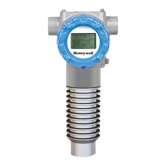
Honeywell SLG 700 User Manual
Smartline level transmitter guided wave radar
Hide thumbs
Also See for SLG 700:
- Option manual (220 pages) ,
- User manual (198 pages) ,
- Quick start manual (40 pages)
Table of Contents
Advertisement
Quick Links
Download this manual
See also:
User Manual
Advertisement
Table of Contents

Related Manuals for Honeywell SLG 700


Summary of Contents for Honeywell SLG 700
- Page 1 SLG 700 SmartLine Level Transmitter Guided Wave Radar User’s Manual 34-SL-25-11 Revision 7.0 February 2017 Honeywell Process Solutions...
- Page 2 In no event is Honeywell liable to anyone for any indirect, special, or consequential damages. The information and specifications in this document are subject to change without notice.
- Page 3 This manual is a detailed how to reference for installing, wiring, configuring, starting up, operating, maintaining, calibrating, and servicing Honeywell’s family of SLG 700 SmartLine Guided Wave Radar Level Transmitters. Users who have a Honeywell SLG 700 SmartLine Guided Wave Radar Level Transmitter configured for HART protocol are referred to the ...
- Page 4 Manual, Document #34- SL-25-07 SLG 700 SmartLine Level Transmitter Product Specification Document #34-SL-03-03 Patents The Honeywell SLG 700 SmartLine Guided Wave Radar Level Transmitter family is covered by U.S. Patents 6055633, 9329072, 9329073, 9476753 and 9329074 their foreign equivalents and other patents pending.
- Page 5 Chassis Ground: Identifies a connection to the chassis or frame of the equipment shall be bonded to Protective Earth at the source of supply in accordance with national and local electrical code requirements. SLG 700 SmartLine Level Transmitter User’s Manual Revision 7 Page v...
- Page 6 The Ex mark means the equipment complies with the requirements of the European standards that are harmonized with the 2014/68/EU Directive (ATEX Directive, named after the French "ATmosphere EXplosible"). SLG 700 SmartLine Level Transmitter User’s Manual Page vi Revision 7...
-
Page 7: Table Of Contents
Materials (plastic vs. metal) ....................26 Blocking distance high and blocking distance low guidance ..........27 2.7.1 Blocking distance high (BDH) guidance ................27 2.7.2 Blocking distance low (BDL) guidance ................27 SLG 700 SmartLine Level Transmitter User’s Manual Revision 7 Page vii... - Page 8 Advanced Displays ......................104 4.4.2 Button operation during monitoring ................. 106 Changing the Default Failsafe Direction and Write Protect Jumpers (Including Simulation mode) 107 4.5.1 Procedure to Establish Failsafe Operation ..............107 SLG 700 SmartLine Level Transmitter User’s Manual Page viii Revision 7...
- Page 9 Conditions of Use for Ex Equipment, “Hazardous Location Equipment” or "Schedule of Limitations" ............................154 Control Drawing ........................156 China RoHS ........................159 10 Security ......................160 10.1 How to report a security vulnerability.................. 160 SLG 700 SmartLine Level Transmitter User’s Manual Revision 7 Page ix...
- Page 10 Figure 2-3: Example of FF connection ....................9 Figure 2-4: Example of a FF network ....................11 Figure 2-5: Transmitter nameplate example ..................12 Figure 2-6: Standard SLG 700 Model Number ................... 13 Figure 2-7: Safety certification example ....................13 Figure 2-1: GWR measurement ......................16 Figure 2-2: Sample Echo Curve ......................
- Page 11 Figure 5-6: Communications Housing Assembly ................121 Figure 5-7: Rook Assembly........................ 122 Figure 5-8: - Sensor ribbon cable ...................... 123 Figure 5-9: Location of RF-connector at bottom of sensor housing ..........124 SLG 700 SmartLine Level Transmitter User’s Manual Revision 7 Page xi...
- Page 12 Table 4-11: FOUNDATION Fieldbus Simulation and Write Protect Jumpers ......... 110 Table 5-2: Probe length calculated from spare probe model number..........129 Table 6-1: SLG 700 Standard Diagnostics Messages ................ 133 Table 7-1: Parts ..........................141 SLG 700 SmartLine Level Transmitter User’s Manual...
-
Page 13: Introduction
1 Introduction 1.1 Overview The SLG 700 Guided Wave Radar SmartLine transmitter is an electronic instrument designed to measure levels of liquid and solid materials. Guided Wave Radar (GWR) transmitters use time domain reflectometry with radar pulses guided by a metal probe and reflected off a product surface to determine levels in tanks. -
Page 14: Electronics Housing
Descriptions of the communications protocols are in the Glossary. Optional Display: Table 2-2 lists features of the available display module. SLG 700 SmartLine Level Transmitter User’s Manual Page 2 Revision 7... -
Page 15: Sensor Housing
Provides electrical feed-through to the probe. Each of the SLG720 and SLG726 models have different process connector designs. Note: Each process connector design accepts a sub-set of the full range of probe types. SLG 700 SmartLine Level Transmitter User’s Manual Revision 7 Page 3... -
Page 16: Probe
Installation details of each probe are described in Chapter 3. Table 2-3: Probe Selection Legend Contact the TAC team Single wire Single rod Coaxial (Wire) Level Interface (liquid/liquid) Bubbling/boiling surfaces Low-dielectric constant liquids Foam (liquid surface measurement) SLG 700 SmartLine Level Transmitter User’s Manual Page 4 Revision 7... - Page 17 Liquid or vapor spray could contact probe above surface Disturbing electromagnetic interference in tank Ability to clean probe See the SLG 700 SmartLine Guided-Wave Radar Level Specification, Document #34-SL-03-03. SLG 700 SmartLine Level Transmitter User’s Manual Revision 7 Page 5...
-
Page 18: Communicating With The Transmitter
Primary Variable which may be only one of a number of process or device variables that may be available. SLG 700 supports HART version 7 and its associated backward compatibility. The analog signal is modulated by Frequency Shift Keying (FSK), using frequencies and current amplitude that do not affect analog sensing at the receiver. -
Page 19: Figure 2-2: Example Of Hart Connection Rl
Scroll/search for file name: “HART Device Description (DD) files for Honeywell HART Devices” This .zip file contains the latest version of the DD files for all of Honeywell’s HART field devices. Unzip the file to locate the DD files applicable to the SLG 700 series. - Page 20 Refer to section 3.3.2 for RL information SLG 700 SmartLine Level Transmitter User’s Manual Page 8 Revision 7...
-
Page 21: Foundation
Fieldbus devices from multiple vendors with control system hosts. The DD provides an extended description of each object in the Virtual Field Device (VFD). The Fieldbus Foundation provides the DD for all registered devices on its website, http://www.fieldbus.org/index.php?option=com_mtree&task=viewlink&link_id=1991&ff bstatus=Registered&Itemid=324 SLG 700 SmartLine Level Transmitter User’s Manual Revision 7 Page 9... - Page 22 To set up the DTM on the FDM/Experion refer to the FDM/Experion User Guide. Figure 2-4 shows an example of a FF network setup. For more information on Experion go to: https://www.honeywellprocess.com/integrated-control-and-safety-systems/experion-pks/ SLG 700 SmartLine Level Transmitter User’s Manual Page 10 Revision 7...
-
Page 23: Slg 700 Transmitter Nameplate
Figure 2-5) and lists the following properties: Model number Physical configuration Power supply voltage Maximum working pressure rating Certification, if ordered (SIL and CRN) SLG 700 SmartLine Level Transmitter User’s Manual Revision 7 Page 11... -
Page 24: Figure 2-5: Transmitter Nameplate Example
CUSTOMER ID: User-defined identifier, if ordered, otherwise blank. HOUSING CONNECTION TYPE: Conduit fitting size: ½” NPT or M20 ASSEMBLED IN / MADE BY HONEYWELL: The country where the transmitter was assembled and tested. SIL INFORMATION: SIL 2/3 Capable is indicated if SIL certification applies, otherwise blank. -
Page 25: Transmitter Model Number Description
SIL level higher than the statement, without “prior use” justification by the end user or diverse technology redundancy in the design. Refer to the SLG 700 Safety Manual, Document #34-SL-25-05, for additional information. The SIL level will be indicated on the SLG 700 nameplate. -
Page 26: Security Considerations
1.8 Security Considerations The SLG 700 provides several features designed to prevent accidental changes to the device configuration or calibration data. These features include a local display password (HART option), a communication password (HART option), a Hardware Write Protect Jumper and a Software Write Protect configuration parameter. -
Page 27: Radar Level Measurement
The same probe transports the reflected pulses from the measured material back to the transmitter. The SLG 700 uses many very-low-power pulses with a technique called Equivalent-Time Sampling (ETS) to efficiently extract level information. Figure 2-2 is an example of a waveform acquired with the ETS method. -
Page 28: Figure 2-1: Gwr Measurement
Figure 2-1: GWR measurement = Dielectric Constant of Vapor Dielectric Constant of Level (Upper Product) Dielectric Constant of Interface (Lower Product) SLG 700 SmartLine Level Transmitter User’s Manual Page 16 Revision 7... -
Page 29: Interface And Flooded Measurements
(DC ) of the upper layer. The SLG 700 can measure levels of different materials in the same tank and can detect the echo from the boundary between Vapor and the Upper Product (UP), and between the Upper Product (UP) and the Lower Product (LP). -
Page 30: Signal Processing Configuration
Figure 2-3: Interface measurement 2.3 Signal processing configuration SLG 700 series level transmitters employ advanced signal processing techniques in order to get the most accurate measurements possible. Complete pulse-shape information including amplitude, width and side-lobe attenuation is used for level detection in order to minimize the influence of signal interferences. A typical pulse and the associated parameters is shown onFigure 2-4. -
Page 31: Amplitude Tracking
Field or Obstacle background is in use and the Dielectric Constant of the Upper Product is above 12. It should not be enabled for products with low Dielectric Constants or when the Built-in background type is being used. SLG 700 SmartLine Level Transmitter User’s Manual Revision 7 Page 19... -
Page 32: Signal Interferences And Background Echoes
(static) background echo and will revert to this if the dynamic background feature is once again disabled. Re-enabling dynamic background at that point starts the process anew. It is recommended that this feature is turned on in all SLG 700 SmartLine Level Transmitter User’s Manual Page 20 Revision 7... -
Page 33: Accuracy And Measurement Range Specifications
For the following four figures in this section, T and T are upper and lower transition zones respectively. Figure 2-5: Upper transition zone length and minimum blocking distance high (BDH) SLG 700 SmartLine Level Transmitter User’s Manual Revision 7 Page 21... -
Page 34: Figure 2-6: Upper Transition Zone Length And Minimum Blocking Distance High (Bdh) And Minimum Blocking Distance Low (Bdl) For Coax Probes In Oil
(BDL) for coax probes in water. Figure 2-6: Upper transition zone length and minimum blocking distance high (BDH) and minimum blocking distance low (BDL) for coax probes in oil. SLG 700 SmartLine Level Transmitter User’s Manual Page 22 Revision 7... -
Page 35: Figure 2-7: Transition Zone Lengths And Minimum Blocking Distance High (Bdh) For Single Lead Probes In Water
30 meters can be measured. In contrast, in strongly absorbing upper media, only upper product thicknesses of less than a couple of meters can be measured. SLG 700 SmartLine Level Transmitter User’s Manual Revision 7 Page 23... - Page 36 15cm or if the measurement of thin interfaces is inaccurate, it might be necessary to adjust the reflection models using the Honeywell DTM. Refer to the SLG 700 HART Option manual, #34-SL-25-06 for details on adjusting model parameters.
-
Page 37: Process Applications
2.5 Process Applications The SLG 700 Level transmitter is designed to work with a wide range of process conditions. Single fluids or interface measurements can be made. Measurements can be made in turbulent conditions or foaming conditions. However, in some situations special precautions must be taken. -
Page 38: Container Considerations
2.6 Container Considerations 2.6.1 Shapes The SLG 700 transmitter may be used in any shape of container. In general, it is designed to be mounted vertically on top of the container, although angled mounting is also possible. See section 3.2.6 for angled mounting limitations. -
Page 39: Blocking Distance High And Blocking Distance Low Guidance
Refer to the SLG 700 HART Option manual, #34-SL-25-06 or the SLG 700 FOUNDATION Fieldbus manual, #34-SL-25-07, for details on adjusting model parameters. -
Page 40: Transmitter Installation
Honeywell’s SmartLine Application and Validation Tool (AVT) will come with parameters pre-loaded so that the transmitter will give accurate level measurements out-of-the-box. Refer to SLG 700 HART Option Manual, #34-SL-25-06 or the SLG 700 FOUNDATION Fieldbus manual, #34-SL-25-07. -
Page 41: Tools
Retaining ring pliers for internal SCA SCB) diameter 40mm Rod probe cut to length Metal saw Wire probe cut to length Saw or bolt cutter Remote mounting transmitter to bracket Phillips screwdriver SLG 700 SmartLine Level Transmitter User’s Manual Revision 7 Page 29... -
Page 42: Mechanical Installation
Measure for correct probe length and check that your probe is within tensile or bending load limits. See section 3.2.2.1 for details. See Table 3-13: Probe length for different probe types 3.2.2 Accuracy and measuring range specifications See section 2.4.3 SLG 700 SmartLine Level Transmitter User’s Manual Page 30 Revision 7... -
Page 43: Table 3-3: Sensor Details - All Models
Table 3-5: Maximum measurement range for each probe type versus dielectric constant. Wire Coax Min DC Range Min DC Range Min DC Range 15m (49ft) 6.3m (21ft) 6.3m (21ft) Probe 25m (82ft) 42m (138ft) 46m (151ft) 50m (164ft) SLG 700 SmartLine Level Transmitter User’s Manual Revision 7 Page 31... - Page 44 SLG 700 SmartLine Level Transmitter User’s Manual Page 32 Revision 7...
-
Page 45: Figure 3-1: Slg720 Probe Dimensions, Mm [In]
Figure 3-1: SLG720 probe dimensions, mm [in] Figure 3-2: SLG726 Threaded process connection probe dimensions; mm [in] SLG 700 SmartLine Level Transmitter User’s Manual Revision 7 Page 33... -
Page 46: Figure 3-3: Slg726 Flanged Process Connection Probe Dimensions; Mm [In]
Figure 3-3: SLG726 Flanged process connection probe dimensions; mm [in] SLG 700 SmartLine Level Transmitter User’s Manual Page 34 Revision 7... -
Page 47: Table 3-6: Tensile Load Limits For Flexible Probe
Torque [Nm]* SLG720 Coax 22mm, 2m (6′) segments SLG726 Coax 42mm, 2m (6′) segments *For an angle mounted probe reduce these limits by 50% to allow for bending from gravity. SLG 700 SmartLine Level Transmitter User’s Manual Revision 7 Page 35... - Page 48 4.0Nm, or 2.0Nm, therefore fluid velocity of 0.3m/s exceeds this limit. Bending Torque [M] on 8mm rod probe v=0.2m/s v=0.3m/s v=0.4m/s Probe length [L] in meters SLG 700 SmartLine Level Transmitter User’s Manual Page 36 Revision 7...
-
Page 49: Trim The Probe Length
Due to numerous spacers along the length of a coaxial probe, it is not recommended to shorten coaxial probes. If a coaxial probe is not the specified length, contact Honeywell’s Technical Assistance Center as a new probe could be required / ordered. -
Page 50: Attach/Assemble The Probe
Note: For flanged SLG726 models, ensure the nut does not intrude into the process connector. See Figure 3-6 for more information. Process Connector Lock Washer Central Connector Rod Segment Lock Washer Stud Rod End Figure 3-5: Rod probe assembly SLG 700 SmartLine Level Transmitter User’s Manual Page 38 Revision 7... -
Page 51: Figure 3-6: Slg726 Flanged Process Connection, Probe Nut Installation Position, Mm [In]
Note: Torque set screws to 6Nm (4.4ft-lbs) Note: For flanged SLG726 models, ensure the nut does not intrude into the bore of the process connector. See Figure 3-6 for more information. SLG 700 SmartLine Level Transmitter User’s Manual Revision 7 Page 39... -
Page 52: Figure 3-7: Wire Probe Assembly
Depending on the final length of the probe, the construction method may differ. For the flanged HTHP, when constructing the probe, the nut Note: should not intrude into the body of the process connector. SLG 700 SmartLine Level Transmitter User’s Manual Page 40 Revision 7... - Page 53 Note: Tighten connection point to the following torque: SLG720 30Nm (22ft-lbs). It is recommended that a process compatible thread locking compound (i.e. Loctite 242) be used on the outer conductor threaded joints. SLG 700 SmartLine Level Transmitter User’s Manual Revision 7 Page 41...
- Page 54 Note: Tighten connection point to the following torque: SLG720 30Nm (22ft-lbs) It is recommended that a process compatible thread locking compound (i.e. Loctite 242) be used on the outer conductor threaded joints. SLG 700 SmartLine Level Transmitter User’s Manual Page 42 Revision 7...
-
Page 55: Figure 3-8: Slg720 Coaxial Probe Assembly (Single Outer Tube Depicted)
Figure 3-8: SLG720 Coaxial probe assembly (single outer tube depicted) SLG 700 SmartLine Level Transmitter User’s Manual Revision 7 Page 43... - Page 56 Tip: To ease assembly, construct the coaxial probe vertically, by suspending the transmitter by the process connector on a hoist or crane. Refer to Figure 3-9 for the SLG726. SLG 700 SmartLine Level Transmitter User’s Manual Page 44 Revision 7...
- Page 57 Note: Tighten connection point to the following torque: SLG726 30Nm (22ft-lbs) It is recommended that a process compatible thread locking compound (i.e. Loctite 242) be used on the outer conductor threaded joints. SLG 700 SmartLine Level Transmitter User’s Manual Revision 7 Page 45...
- Page 58 Insert 2 M3 set screws into each coupler. Note: Tighten M3 set screws to 1.0Nm (8.8in-lb). It is recommended that a process compatible thread locking compound (i.e. Loctite 242) be used on each set screw. SLG 700 SmartLine Level Transmitter User’s Manual Page 46 Revision 7...
-
Page 59: Figure 3-9: Slg726 Coaxial Probe Assembly
(Segmented outer tube depicted) 3.2.4.4 No probe option For those users who wish to supply their own rod or rope, the SLG 700 transmitter is available with a no probe option (SLGXXX-000). Note: Users should not attempt to supply their own coaxial probes. -
Page 60: Centering Disks And Configured Probe Length
See Figure 3-10 and Figure 3-11 for recommended location of holes and assembly details of the centering disk. Secure the cotter pin by bending the leads back once installed. See Table 3-11 and Table 3-12 for details. SLG 700 SmartLine Level Transmitter User’s Manual Page 48 Revision 7... -
Page 61: Figure 3-10: Recommended Location Of Holes For Rod Probes
Figure 3-10: Recommended location of holes for rod probes SLG 700 SmartLine Level Transmitter User’s Manual Revision 7 Page 49... -
Page 62: Figure 3-11: Centering Disks For Wire And Rod Probes
8” 6” 6” Table 3-12: Centering disk dimensions Centering disk size Actual disc diameter 2” 1.8″ (45mm) 3” 2.7” (68mm) 4” 3.6” (92mm) 6” 5.5” (141mm) 8” 7.4” (188mm) SLG 700 SmartLine Level Transmitter User’s Manual Page 50 Revision 7... -
Page 63: Figure 3-12: Probe Length Definition For Rod Probes Using A Centering Disk
Wire probes L - 125mm Note: "L" is the probe length specified in the transmitter model number Figure 3-12: Probe length definition for rod probes using a centering disk SLG 700 SmartLine Level Transmitter User’s Manual Revision 7 Page 51... -
Page 64: Mounting The Transmitter
3.2.6 Mounting the transmitter In the following dimension figures, “R” denotes the transmitter reference plane. 3.2.6.1 SLG720 Transmitter dimensions Figure 3-13: Flanged SLG720 Transmitter, mm [in] SLG 700 SmartLine Level Transmitter User’s Manual Page 52 Revision 7... -
Page 65: Figure 3-14: Threaded (Npt ¾", 1", 1½", 2") Slg720 Transmitter, Mm [In]
Figure 3-14: Threaded (NPT ¾", 1", 1½", 2") SLG720 Transmitter, mm [in] SLG 700 SmartLine Level Transmitter User’s Manual Revision 7 Page 53... -
Page 66: Figure 3-15: Threaded (Bsp/G ¾", 1", 1½") Slg720 Transmitter, Mm [In]
Figure 3-15: Threaded (BSP/G ¾”, 1”, 1½”) SLG720 Transmitter, mm [in] SLG 700 SmartLine Level Transmitter User’s Manual Page 54 Revision 7... -
Page 67: Figure 3-16: Flanged Slg726 Transmitter, Mm [In]
SLG726 Transmitter dimensions 3.2.6.2 Figure 3-16: Flanged SLG726 transmitter, mm [in] SLG 700 SmartLine Level Transmitter User’s Manual Revision 7 Page 55... -
Page 68: Figure 3-17: Threaded (Npt 1½", 2") Slg726 Transmitter, Mm [In]
Figure 3-17: Threaded (NPT 1½", 2”) SLG726 transmitter, mm [in] SLG 700 SmartLine Level Transmitter User’s Manual Page 56 Revision 7... -
Page 69: Figure 3-18: Threaded (Bsp/G 1½") Slg726 Transmitter, Mm [In]
Figure 3-18: Threaded (BSP/G 1½") SLG726 transmitter, mm [in] SLG 700 SmartLine Level Transmitter User’s Manual Revision 7 Page 57... -
Page 70: Suitable Mounting Position
500mm (20″) 500mm (20″) Single wire 100mm (4″) 500mm (20″) 500mm (20″) Single rod 100mm (4″) 0mm (0″) 0mm (0″) 0mm (0″) Coax SLG 700 SmartLine Level Transmitter User’s Manual Page 58 Revision 7... -
Page 71: Optimum Operating Temperature
Backgrounds can be taken using the Honeywell DTM, the local display, or the supported handhelds. The DTM instructions can be found in the SLG 700 HART option manual 34-SL-25-06. -
Page 72: Temperature Requirements
The SLG726 (high pressure high temperature (HTHP) process connector) must be pressure de-rated at elevated temperatures. The pressure rating at operating temperature is specified in Figure 3-22 and in tabular form in Table 3-15. Figure 3-20: SLG720 temperature limits SLG 700 SmartLine Level Transmitter User’s Manual Page 60 Revision 7... -
Page 73: Figure 3-21: Slg726 Temperature Limits
Figure 3-21: SLG726 temperature limits Figure 3-22: SLG726 Maximum pressure based on maximum operating temperature SLG 700 SmartLine Level Transmitter User’s Manual Revision 7 Page 61... -
Page 74: Table 3-15: Slg726 Maximum Pressure Based On Maximum Operating Temperature In Tabular Form
Table 3-15: SLG726 Maximum pressure based on maximum operating temperature in tabular form AMBIENT TEMPERATURE [ MAX PRESSURE [bar] INTRINSICALLY SAFE (IS) NON-(IS) SLG 700 SmartLine Level Transmitter User’s Manual Page 62 Revision 7... -
Page 75: Figure 3-23: Flanged Tank Connection
Ensure correct functionality: To ensure a reliable electrical contact between the tank and transmitter, use unpainted, metal bolts. Figure 3-23: Flanged tank connection SLG 700 SmartLine Level Transmitter User’s Manual Revision 7 Page 63... -
Page 76: Figure 3-24: Flange Mounting
In certain applications taller nozzles may be accommodated but near zone performance at the exit of the nozzle may be reduced. For nozzle dimensions that do not meet the requirements outlined in Table 3-16 contact the Honeywell Technical Assistance Center. SLG 700 SmartLine Level Transmitter User’s Manual Page 64 Revision 7... -
Page 77: Figure 3-25: Oversized Nozzle Configuration
Where an 8” nozzle (or greater) is the only installation option, use Figure 3-26 as a guideline. Nozzle lower edge Plate approximately flush with lower edge of the nozzle Plate Pipe diameter 150mm (6”). Where 1 = 8” diameter Figure 3-25: Oversized nozzle configuration SLG 700 SmartLine Level Transmitter User’s Manual Revision 7 Page 65... -
Page 78: Figure 3-26: Threaded Tank Connection
For tanks with BSP/G threads, place a gasket on top of the tank, or use a sealant on the threads of the tank connection. Figure 3-26: Threaded tank connection Figure 3-27: Tank roof mounting using threaded connection SLG 700 SmartLine Level Transmitter User’s Manual Page 66 Revision 7... -
Page 79: Figure 3-28: Bypass Installation
Mounting on a bypass / bridle 3.2.9.5 SLG 700 transmitter can be successfully installed in a new or existing bypass pipe, bridle, or a side pipe as shown in Figure 3-28. This type of installation is often simpler and allows the addition of radar level measurement to an otherwise busy installation. -
Page 80: Mounting On A Non-Metallic Container
Both Figure 3-29 and Figure 3-30 are considered non-metallic mounts. Both types of mountings are subject to the same specifications. SLG 700 SmartLine Level Transmitter User’s Manual Page 68 Revision 7... -
Page 81: Figure 3-30: Mounting In Concrete Silos
Secure the electronics module to the bracket with the 3 supplied M6 screws. Connect the cable and check bends for minimum radius (see Figure 3-31) to prevent damage. Torque the 2 nuts to 6Nm (4.4ft-lbs). SLG 700 SmartLine Level Transmitter User’s Manual Revision 7 Page 69... -
Page 82: Figure 3-31: Remote Mount
Figure 3-31: Remote mount SLG 700 SmartLine Level Transmitter User’s Manual Page 70 Revision 7... -
Page 83: Rotate Transmitter Housing
For wire probes with end weights, the end weight has an internal M10x1.5 thread. This thread can be used to attach various mounting hardware (customer supplied). Alternatively the weight can be removed and a clamp can be used. See Figure 3-33. SLG 700 SmartLine Level Transmitter User’s Manual Revision 7 Page 71... -
Page 84: Figure 3-33: Anchoring Wire Probes
When anchoring a wire probe it is recommended that the wire be slack to prevent excessive tensile loading from motion of medium and/or thermal expansion. The sag should be ~1cm/m (1.5″/10′) of the probe length. See Figure 3-34. Figure 3-34: Wire probe slack SLG 700 SmartLine Level Transmitter User’s Manual Page 72 Revision 7... -
Page 85: Figure 3-35: Anchoring Coaxial Probes
Coaxial probes can be guided by a tube welded to the bottom of a tank. Make sure that the coaxial probe can move freely to allow for thermal expansion. Figure 3-35: Anchoring coaxial probes SLG 700 SmartLine Level Transmitter User’s Manual Revision 7 Page 73... -
Page 86: Install Conduit Entry Plugs And Adapters
(NPT), a non-hardening thread sealant may be used. Thread the appropriate size adapter (M20 or ½ NPT) into the conduit entry opening Using a 1-1/4” wrench tighten adapters to torque 32Nm (24lb-ft). SLG 700 SmartLine Level Transmitter User’s Manual Page 74 Revision 7... -
Page 87: Flange Pressure Ratings
Low Temperature Region: PEEK GF30, Gold over Nickel plate on Brass Alloy 360, Gold over Nickel plate on Beryllium Copper Alloy 172 HT, and seal materials (Gold Plated Alloy 718 or Silver with Gold underlay plated 17-4PH). SLG 700 SmartLine Level Transmitter User’s Manual Revision 7 Page 75... -
Page 88: Electrical Installation
Figure 3-36: Transmitter operating ranges. 3.3.2 HART / 4-20mA Voltage Operating Ranges Supply Voltage Max. Loop (Vdc) Resistance (Ohms) 19.5 1200 1284 Figure 3-36: Transmitter operating ranges SLG 700 SmartLine Level Transmitter User’s Manual Page 76 Revision 7... - Page 89 Loop current wiring should never be connected to the TEST “+” terminal. This can damage the Transmitter. Additionally, never connect the current measurement device between the Loop “+” terminal and the TEST “+”terminal. This also will damage the Transmitter. SLG 700 SmartLine Level Transmitter User’s Manual Revision 7 Page 77...
-
Page 90: Terminal Connections
Grounding may be required to meet various approval body certification,for example CE conformity. Refer to the Appendix of this document for details. The right-most terminal is for 4-20mA loop test and not applicable for Note: FOUNDATION Fieldbus. SLG 700 SmartLine Level Transmitter User’s Manual Page 78 Revision 7... - Page 91 SLG 700 SmartLine Level Transmitter User’s Manual Revision 7 Page 79...
-
Page 92: Foundation Fieldbus
Plug the unused conduit entrance with a conduit plug appropriate for the environment. Connect the positive loop power lead and the negative loop power. The Transmitter is polarity insensitive. Replace the end cap, and secure it in place. SLG 700 SmartLine Level Transmitter User’s Manual Page 80 Revision 7... - Page 93 SLG 700 SmartLine Level Transmitter User’s Manual Revision 7 Page 81...
-
Page 94: Lightning Protection
3.3.8 Process Sealing The SLG 700 SmartLine Guided Wave Radar Level Transmitter is available as FM and CSA-certified as a Dual Seal device in accordance with ANSI/ISA–12.27.01–2003, “Requirements for Process Sealing between Electrical Systems and Flammable, or Combustible Process Fluids”. -
Page 95: Operating The Transmitter
HART or FF. Honeywell supplies user interfaces for both HART and FF. Refer to respective HART or Fieldbus manual for more information. Honeywell provides DD and DTM files for the SLG 700 transmitters. The files may be downloaded from Honeywell’s website: https://www.honeywellprocess.com/en-US/explore/products/instrumentation/process-level-... -
Page 96: Three-Button Operation
4.2 Three-Button Operation The SLG 700 optional three-button interface provides a user interface and operation capability without exposing the transmitter electronics. Figure 4-1 shows the location of the three-button option and the labels for each button. The buttons are accessible by loosening the rightmost screw and rotating the covering nameplate. -
Page 97: Menu Navigation
All numeric entries are clamped at the low or high limit if needed. To show the low and high limit for a parameter, put the cursor over the left-most digit, select either the ▲ or ▼ character and press button. SLG 700 SmartLine Level Transmitter User’s Manual Revision 7 Page 85... -
Page 98: Editing A Numeric Value
3. Press or to scroll through the list of choices. 4. Press to make your selection. The new selection will be stored in the transmitter and will be displayed on the lower line, right justified. SLG 700 SmartLine Level Transmitter User’s Manual Page 86 Revision 7... -
Page 99: The Advanced Display Menu
HART Params Monitor Critical Diag For details see Non-Critical Diag Table 4-8: Monitor sub-menu page 99. Device Vars Display Info Comm Info Sensor Info Echo Stem Plot Model Number SLG 700 SmartLine Level Transmitter User’s Manual Revision 7 Page 87... -
Page 100: Correlation Model Recalculation
Vapor Attenuation Transmitter Model, Probe Type Minimum BDH/BDL Vapor DC, Upper DC, Lower DC, Probe Type, Application Type BDH/BDL Vapor DC, Upper DC, Lower DC, Probe Type, Application Type SLG 700 SmartLine Level Transmitter User’s Manual Page 88 Revision 7... -
Page 101: Table 4-5: Display Config Sub-Menu
Activate rotation between up to 8 screens. menu selection If user selects ‘Yes’ , and to select screens would rotate number. automatically based on to enter configured Rotation Time. SLG 700 SmartLine Level Transmitter User’s Manual Revision 7 Page 89... - Page 102 Press to enter Decimals None Select the decimal (FF read only) resolution for the PV. menu selection and to select X.XX from list. X.XXX to enter SLG 700 SmartLine Level Transmitter User’s Manual Page 90 Revision 7...
-
Page 103: Table 4-6: Basic Configuration Sub-Menu
to select from list, to ft/min enter in/s Select the Volume unit for all Volume- related parameters US gal Volume Unit imp gal bbl oil bbl liq SLG 700 SmartLine Level Transmitter User’s Manual Revision 7 Page 91... - Page 104 and to Echo Lost Time ###.### Time in seconds until a PV select from Bad fault occurs after the list, to echo is no longer enter detected. SLG 700 SmartLine Level Transmitter User’s Manual Page 92 Revision 7...
- Page 105 Guided Wave Radar Level. (HART only) to execute Set URV ATTENTION: Executing this service will set the Upper Range Value (URV) equal to the input Guided Wave Radar Level. SLG 700 SmartLine Level Transmitter User’s Manual Revision 7 Page 93...
- Page 106 1 Jan 1972 is displayed. You cannot delete or overwrite the Install Date when written to the transmitter. Write Date Configures the date as provided by user. SLG 700 SmartLine Level Transmitter User’s Manual Page 94 Revision 7...
-
Page 107: Table 4-7: Advanced Config Sub-Menu
Table 4-7: Advanced Config sub-menu This table describes the Advanced Display menu’s “Advance Config” sub-menu. Advanced configuration is described in detail in the SLG 700 HART Option manual, #34-SL-25-06. <Return> Return to the Level 1 menu Level 3 Description Action Level 2 <Return>... - Page 108 Length units Block Dist Low #.### Configures region near the Probe end where measurements are not possible and inaccurate. Value entered is considered to be in Length units SLG 700 SmartLine Level Transmitter User’s Manual Page 96 Revision 7...
- Page 109 and to Attenuation of the model. Attenuation ##.## select number. to Gain of model. Gain ###### enter and shift to next Objective function ObjFuncThrshld digit threshold of the model. SLG 700 SmartLine Level Transmitter User’s Manual Revision 7 Page 97...
- Page 110 Enter the current year. Month January - Select the current month. December Enter the day of the month. Write Date Press Enter to write the HART Date to the transmitter. SLG 700 SmartLine Level Transmitter User’s Manual Page 98 Revision 7...
- Page 111 Sensor Oscillator (R) FAULT Factory Mode (R) Yes: Sensor is in Factory Mode No: Sensor is in User Mode Yes: Sensor is in low power mode Low Power Mode (R) SLG 700 SmartLine Level Transmitter User’s Manual Revision 7 Page 99...
- Page 112 Out of Range: PV is not within the range limits PV Range (R) Out Of Range OVERTEMP: Sensor temperature is greater Sensor Over Temp (R) than 125°C. OVER TEMP SLG 700 SmartLine Level Transmitter User’s Manual Page 100 Revision 7...
- Page 113 Custom: Device is calibrated for user- defined points. Yes: The Field Background is not FldBkgdNotCompat compatible. Backgrnd Not Set Yes: The Background is not set. FldgBkgdLoadError Yes: Field Background loading error. SLG 700 SmartLine Level Transmitter User’s Manual Revision 7 Page 101...
- Page 114 20mA. <Return> Firmware Version Firmware version of sensor module Sensor Info Model Key Type and range of transmitter Device ID Unique for each device considered as serial number SLG 700 SmartLine Level Transmitter User’s Manual Page 102 Revision 7...
- Page 115 (no mismatch only) Matching Source Source of Model Number to match. (mismatch only) Sensor Module Comm Module Do Match Perform the Model Number match. (mismatch only) (R) Read-Only parameter SLG 700 SmartLine Level Transmitter User’s Manual Revision 7 Page 103...
-
Page 116: Monitoring The Advanced Display
PV Trend: User-configurable display period from 1 to 999 hours. The chart displays minimum, maximum, and average of the configured PV over the selected trend period. Process Bar Graph Trend Variable Figure 4-2: Advanced Display Formats with the Process Variable SLG 700 SmartLine Level Transmitter User’s Manual Page 104 Revision 7... -
Page 117: Table 4-9: Advanced Displays With Pv Format Display Indications
If the PV exceeds the values above limits, the PV is divided by 1000 and K is appended to the result, allowing a maximum value with multiplier of 999999K or -99999K SLG 700 SmartLine Level Transmitter User’s Manual Revision 7 Page 105... -
Page 118: Button Operation During Monitoring
When the operator screens are active on the Advanced Display, the Increment and Decrement buttons ( and ) can be used to move to the next or previous operator screen SLG 700 SmartLine Level Transmitter User’s Manual Page 106 Revision 7... -
Page 119: Changing The Default Failsafe Direction And Write Protect Jumpers (Including Simulation Mode)
Loosen the end cap lock, and unscrew the end cap from the electronics side of the Transmitter housing. If equipped with a Display module, carefully depress the two tabs on the sides of the Display module, and pull it off. SLG 700 SmartLine Level Transmitter User’s Manual Revision 7 Page 107... - Page 120 Orient the Display for proper viewing through the end cap window. You can rotate ° the mounting orientation in 90 increments. Restore transmitter power if removed. SLG 700 SmartLine Level Transmitter User’s Manual Page 108 Revision 7...
-
Page 121: Figure 4-3: Locating The Failsafe And Write Protect Jumpers
& Table 4-10 4-10 for Jumper config. settings Figure 4-3: Locating the Failsafe and Write Protect Jumpers SLG 700 SmartLine Level Transmitter User’s Manual Revision 7 Page 109... -
Page 122: Table 4-10: Hart Failsafe And Write Protect Jumpers
Fieldbus SIM Mode = ON Write Protect = OFF (Not Protected) Changes to configurations and calibrations are disabled when the Note: jumpers are set in the write-protect positions. Write-protect includes disabling password access. SLG 700 SmartLine Level Transmitter User’s Manual Page 110 Revision 7... -
Page 123: Maintenance
If the transmitter is installed in contact with a sticky or viscous medium, a periodic cleaning may be required. The frequency of cleaning should be adjusted based on application needs and visual inspection. SLG 700 SmartLine Level Transmitter User’s Manual Revision 7 Page 111... - Page 124 SLG 700 SmartLine Level Transmitter User’s Manual Page 112 Revision 7...
- Page 125 SLG 700 SmartLine Level Transmitter User’s Manual Revision 7 Page 113...
-
Page 126: Procedures
(URV) are then set by commands from the MC Toolkit. The Transmitter does not measure the given PV input or update the PV output while it operates in the Output mode. SLG 700 SmartLine Level Transmitter User’s Manual Page 114 Revision 7... -
Page 127: Constant Current Source Mode Procedure
5. Select the desired constant-level Output: 0%, 100%, or Other (any between 0% - 100%). 6. Select the Set button. A box will be displayed asking Are you sure you want to place the transmitter in output mode? SLG 700 SmartLine Level Transmitter User’s Manual Revision 7 Page 115... -
Page 128: Replacing The Terminal Block
Refer to Installing the Terminal Block Module, Document #34-ST-33-64. 5.3.4 Replacing the Display Assembly Refer to Installing the Display Module, Document #34-ST-33-65. 5.3.5 Replacing the Communication Module Refer to Installing the Communication Module, Document #34-ST-33-69. SLG 700 SmartLine Level Transmitter User’s Manual Page 116 Revision 7... -
Page 129: How To Replace The Sensor Housing
Display Module, remove the two setscrews. Depress the two tabs on the Display Module and remove it. Unplug the ribbon cable from the Communication Module. Do not discard any of the parts. SLG 700 SmartLine Level Transmitter User’s Manual Revision 7 Page 117... - Page 130 Housing. Plug the Display Module into the Communication Module. Screw the end cap into the Electronic Housing. Re-insert the transmitter to the mounting. Angle as required. Turn power ON. SLG 700 SmartLine Level Transmitter User’s Manual Page 118 Revision 7...
-
Page 131: Replacing Gwr Sensor Electronics
An example of a correct date code is shown in Figure 5-4 1.010000 and 1.020000 Sensor electronics is replaceable Figure 5-4: Part Number and Date Code (D/C) label on bottom of Terminal PCBA assembly SLG 700 SmartLine Level Transmitter User’s Manual Revision 7 Page 119... -
Page 132: Figure 5-5: Location Of Sensor Housing And Attachment Set Screws
5. Separate the sensor housing from the process connector by first loosening the 4 mm setscrews (3) and gently separating the sensor electronics housing. Do not discard setscrews or o-rings. Figure 5-5: Location of sensor housing and attachment set screws SLG 700 SmartLine Level Transmitter User’s Manual Page 120 Revision 7... -
Page 133: Figure 5-6: Communications Housing Assembly
There should be 2.5mm clearance between the Communications housing and the top fin of the Sensor electronics housing. The o-ring should not be visible. Over-tightening will irreparably damage the ribbon cable. Ensure the o-ring is not pinched SLG 700 SmartLine Level Transmitter User’s Manual Revision 7 Page 121... -
Page 134: Figure 5-7: Rook Assembly
Carefully align and connect the Sensor Ribbon Cable to the connector “P2” at the bottom of the Communication Module. Pin 1 must be aligned with contact 1 of the ribbon cable indicated by the colored edge wire. SLG 700 SmartLine Level Transmitter User’s Manual Page 122 Revision 7... -
Page 135: Figure 5-8: - Sensor Ribbon Cable
Apply O-ring lubricant to the end cap o-ring before installing the end cap. Reinstall the end cap and tighten the end cap locking screw. SLG 700 SmartLine Level Transmitter User’s Manual Revision 7 Page 123... -
Page 136: Figure 5-9: Location Of Rf-Connector At Bottom Of Sensor Housing
See manuals: Publication # Publication Title SLG 700 SmartLine Guided Wave Radar User’s Manual 34-SL-25-11 34-SL-25-06 SLG 700 SmartLine Level Transmitter Guided Wave Radar HART© Option User’s Manual... -
Page 137: Hazardous Locations
The Hi-Pot test may be performed on the transmitter electronics, before re-installing on the process connector. SLG 700 SmartLine Level Transmitter User’s Manual Revision 7 Page 125... -
Page 138: Replacing The Wire Probe
Publication # Publication Title SLG 700 SmartLine Guided Wave Radar User’s Manual 34-SL-25-11 © 34-SL-25-06 SLG 700 SmartLine Level Transmitter Guided Wave Radar HART Option User’s Manual 34-SL-25-07 SLG 700 SmartLine Level Transmitter Guided Wave Radar FOUNDATION Fieldbus Option Manual 5.4.6 Tools required... -
Page 139: Procedures
1.010000: a change of probe type to multi-twist wire is supported. Either a HART or FF user interface is required to make the appropriate settings change. c) 1.020000: a change of probe type to multi-twist wire is supported with all interfaces. SLG 700 SmartLine Level Transmitter User’s Manual Revision 7 Page 127... - Page 140 Note: Torque set screws to 6 Nm (4.4 ft-lbs) Note: For flanged SLG726 models, ensure the nut does not intrude into the bore of the process connector. See image below for acceptable spacing. SLG 700 SmartLine Level Transmitter User’s Manual Page 128 Revision 7...
-
Page 141: Table 5-2: Probe Length Calculated From Spare Probe Model Number
SLGP26 / SLG726 MULTI-TWIST SLGP20 / SLG720 0.9985 0.03300 WIRE SLGP26 / SLG726 0.9985 0.04145 e) If a field background is desired, a new field background can be taken. SLG 700 SmartLine Level Transmitter User’s Manual Revision 7 Page 129... - Page 142 If a field background is desired, a new field background can be taken. Instructions pertaining to be included with replacement of multi-twist wire probes: a) Refer to Revision 4.0 of the SLG 700 SmartLine Guided Wave Radar User’s Manual. References below will be to this revision of the manual.
- Page 143 0.9985 and the vapor attenuation should be set to 0.03300 if the model is SLG720 and to 0.04145 if the model is SLG726. SLG 700 SmartLine Level Transmitter User’s Manual Revision 7 Page 131...
-
Page 144: Troubleshooting
6-1Error! Reference source not found. are specific to the Transmitter, exclusive of those associated with the HART protocol. HART diagnostic messages are listed and described in the SLG 700 SmartLine HART Option User Manual, Document #34-SL-25-06. SLG 700 SmartLine Level Transmitter User’s Manual... -
Page 145: Table 6-1: Slg 700 Standard Diagnostics Messages
Table 6-1: SLG 700 Standard Diagnostics Messages Critical Diagnostics Description Resolution (Failure Conditions) Active Diags Read-only field. Displays the number of status flags in the given category which are currently in the Active or Alarm/Warning state. Sensor Module Displays a status for the sensor. - Page 146 Non-Critical Diagnostics Description Resolution (Warning Conditions) SLG 700 SmartLine Level Transmitter User’s Manual Page 134 Revision 7...
-
Page 147: Diagnosing Slg720 Coaxial Probe Misassembly
Blk Dist Lo Zone Bulk Distance Low Zone accurate. The distance within the lower blocking range. 6.2 Diagnosing SLG720 Coaxial Probe misassembly SLG 700 SmartLine Level Transmitter User’s Manual Revision 7 Page 135... - Page 148 Spacer is missing – can see between opposing Spacer is in place – can only see a minimal holes in coaxial tube amount between opposing holes. SLG 700 SmartLine Level Transmitter User’s Manual Page 136 Revision 7...
- Page 149 Correct nut and washer placement. 3. Each section of the tube should be straight to within 2 mm. SLG 700 SmartLine Level Transmitter User’s Manual Revision 7 Page 137...
- Page 150 The point of contact is ~2 m; however, since the level is higher than this position, the false reflection appears further away due to the index of refraction effect. SLG 700 SmartLine Level Transmitter User’s Manual Page 138...
- Page 151 (<1000 counts). The large reflection at 6 m is the end of the probe. This illustrates the importance of proper nut placement. The biggest effect is from a nut missing altogether SLG 700 SmartLine Level Transmitter User’s Manual Revision 7 Page 139...
- Page 152 SLG 700 SmartLine Level Transmitter User’s Manual Page 140 Revision 7...
-
Page 153: Parts List
FOUNDATION Fieldbus Electronics Module Kit (Programmed for 50096656-503 Level) FOUNDATION Fieldbus Electronics Module Kit w/connection for 50096656-504 external configuration buttons (Programmed for Level) Spare sensor Housing (including the sensor electronics) 50096711-501 SLG 700 SmartLine Level Transmitter User’s Manual Revision 7 Page 141... -
Page 154: Glossary
Factory Mutual (FM): Provides third-party certification and approval of commercial and industrial products, including Hazardous Location Electrical Equipment. Field Device Tool (FDT): A general purpose application / tool that allows users to manage many DTMs running their individual transmitters. SLG 700 SmartLine Level Transmitter User’s Manual Page 142 Revision 7... - Page 155 Honeywell Experion: An advanced distributed control system (DCS) and innovative software applications to improve users' business performance and ensures reliable performance. Honeywell Field Device Manager (FDM): A centralized asset management system for remote configuration and maintenance of smart field devices based on HART, PROFIBUS and Fieldbus FOUNDATION protocols.
- Page 156 Upper Range Value (URV): A Basic configuration parameter which allows users to enter the measuring value for which the analog output will be scaled to 20 mA. SLG 700 SmartLine Level Transmitter User’s Manual Page 144 Revision 7...
- Page 157 SLG 700 SmartLine Level Transmitter User’s Manual Revision 7 Page 145...
-
Page 158: Appendix Certifications
A copy of the SLG 700 EU Declaration of Conformity can be downloaded here: https://www.honeywellprocess.com/library/support/Public/Documents/50099165.pdf SLG 700 SmartLine Level Transmitter User’s Manual... -
Page 159: Hazardous Locations Certifications
Ex nA[ia] IIC T4 Ga/Gc Enclosure: Type 4X/ IP66/ IP67. Dual Seal in accordance with ANSI/ISA 12.27.01 All SLG 700 models are registered in Canadian Registration Number (CRN): all provinces and territories in Canada. SLG 700 SmartLine Level Transmitter User’s Manual... - Page 160 Note 1 Fieldbus / FISCO Class l, Zone 2[0], AEx nA[ia Ga] IIC T4 Gc (Remote version only.) Enclosure: Type 4X/ IP66/ IP67. Dual Seal in accordance with ANSI/ISA 12.27.01 SLG 700 SmartLine Level Transmitter User’s Manual Page 148 Revision 7...
- Page 161 Non-incendive with IS probe: 4-20 mA / HART Note 1 (Korea) Ex nA[ia] IIC T4 Gc[Ga] FOUNDATION Certificate #s Note 1 Fieldbus 16-AV4BO-0093X 16-AV4BO-0094X Enclosure: IP66/ IP67 16-AV4BO-0095X 16-AV4BO-0161X 16-AV4BO-0165X 16-AV4BO-0167X SLG 700 SmartLine Level Transmitter User’s Manual Revision 7 Page 149...
- Page 162 0 Ex ia IIC T4 X Note 2b Fieldbus Non-incendive with IS probe: 4-20 mA / HART Note 1 2 Ex nAc[ia] IIC T4 X Note 1 FOUNDATION Fieldbus Enclosure: IP 66/67 SLG 700 SmartLine Level Transmitter User’s Manual Page 150 Revision 7...
- Page 163 SLG 700 SmartLine Level Transmitter User’s Manual Revision 7 Page 151...
- Page 164 – Transmitters ordered with SIL certification will signify the SIL Level on the SLG 700 Nameplate. China Pattern The SLG 700 is approved according to the Law on Metrology of the People’s Republic of China. China Pattern Approval identification numbers Approval 2016-L262, 2016-L263, and 2016-L264.
-
Page 165: Marking Atex Directive
[ ] adjacent to the type of protection used on the equipment certification nameplate. Once a type of protection has been checked on the nameplate, the equipment will not be reinstalled using any of the other certification types. SLG 700 SmartLine Level Transmitter User’s Manual Revision 7 Page 153... -
Page 166: Conditions Of Use For Ex Equipment, "Hazardous Location Equipment" Or "Schedule Of Limitations
EXPLOSIVE ATMOSPHERE MAY BE PRESENT Non-Incendive Equipment WARNING: DO NOT OPEN WHEN AN EXPLOSIVE ATMOSPHERE MAYBE PRESENT All Protective Measures: WARNING: FOR CONNECTION IN AMBIENTS ABOVE 60°C USE WIRE RATED 105°C SLG 700 SmartLine Level Transmitter User’s Manual Page 154 Revision 7... - Page 167 Ta=-50°C to +85°C process temperature = 300°C other protection types Ta=-50°C to +60°C process temperature = 450°C ° ° All models when installed as FISCO Ta= -50 C to 45 SLG 700 SmartLine Level Transmitter User’s Manual Revision 7 Page 155...
-
Page 168: Control Drawing
9.6 Control Drawing SLG 700 SmartLine Level Transmitter User’s Manual Page 156 Revision 7... - Page 169 SLG 700 SmartLine Level Transmitter User’s Manual Revision 7 Page 157...
- Page 170 SLG 700 SmartLine Level Transmitter User’s Manual Page 158 Revision 7...
-
Page 171: China Rohs
9.7 China RoHS China RoHS compliance information can be downloaded here: https://www.honeywellprocess.com/library/support/Public/Documents/50131303.pdf SLG 700 SmartLine Level Transmitter User’s Manual Revision 7 Page 159... -
Page 172: Security
Honeywell investigates all reports of security vulnerabilities affecting Honeywell products and services. To report potential security vulnerability against any Honeywell product, please follow the instructions at: https://honeywell.com/pages/vulnerabilityreporting.aspx Submit the requested information to Honeywell using one of the following methods: Send an email to security@honeywell.com. - Page 173 Mounting on a bypass / bridle ........65 Electronics Housing ............2 Mounting on a non-metallic container ......See Error Messages ............125 European Directive Information (EU) ......136 Nozzle mount ............... 62 SLG 700 SmartLine Level Transmitter User’s Manual Revision 7 Page 161...
- Page 174 Security Considerations ........... 13 Security Considerations ..........13 Sensor Housing ............... 3 Startup Output Check Procedures ........109 Support and Contact Information ........iv Symbol Descriptions and Definitions ......v SLG 700 SmartLine Level Transmitter User’s Manual Page 162 Revision 7...
- Page 175 Honeywell China Inc. Phone: (86-21) 5257-4568 Fax: (86-21) 6237-2826 Singapore Honeywell Pte Ltd. Phone: +(65) 6580 3278 Fax: +(65) 6445-3033 South Korea Honeywell Korea Co Ltd Phone: +(822) 799 6114 Fax: +(822) 792 9015 Specifications are subject to change without notice.
- Page 176 For more information To learn more about Smartline transmitters, visit www.honeywellprocess.com Or contact your Honeywell account manager Process Solutions Honeywell 1250 W Sam Houston Pkwy S Houston, USA, TX 77042 Honeywell Control Systems Ltd Honeywell House, Skimped Hill Lane Bracknell, England, RG12 1EB...