Honeywell SmartLine SLG 700 User Manual
Level transmitter
guided wave radar
Hide thumbs
Also See for SmartLine SLG 700:
- Option manual (220 pages) ,
- User manual (176 pages) ,
- Quick start manual (40 pages)

Related Manuals for Honeywell SmartLine SLG 700


Summary of Contents for Honeywell SmartLine SLG 700
- Page 1 SLG 700 SmartLine Level Transmitter Guided Wave Radar User’s Manual 34-SL-25-11 Revision 8.0 December 2017 Honeywell Process Solutions...
- Page 2 In no event is Honeywell liable to anyone for any indirect, special, or consequential damages. The information and specifications in this document are subject to change without notice.
- Page 3 This manual is a detailed how to reference for installing, wiring, configuring, starting up, operating, maintaining, calibrating, and servicing Honeywell’s family of SLG 700 SmartLine Guided Wave Radar Level Transmitters. Users who have a Honeywell SLG 700 SmartLine Guided Wave Radar Level Transmitter configured for HART protocol are referred to the ...
- Page 4 SLG 700 SmartLine Level Transmitter Product Specification Document #34-SL-03-03 Patents The Honeywell SLG 700 SmartLine Guided Wave Radar Level Transmitter family is covered by U. S. Patents 9329072, 9329073, 9476753 and 9518856 and 9329074, 9574929, 9618612, 9711838 and their foreign equivalents and other patents pending.
- Page 5 Symbols Descriptions and Definitions The following symbols may appear in this document. Symbol Definition ATTENTION: Identifies information that requires special consideration. TIP: Identifies advice or hints for the user, often in terms of performing a task. CAUTION Indicates a situation which, if not avoided, may result in equipment or work (data) on the system being damaged or lost, or may result in the inability to properly operate the process.
- Page 6 Symbol Definition The Canadian Standards mark means the equipment has been tested and meets applicable standards for safety and/or performance. The Ex mark means the equipment complies with the requirements of the European standards that are harmonized with the 2014/68/EU Directive (ATEX Directive, named after the French "ATmosphere EXplosible").
-
Page 7: Table Of Contents
Contents Introduction ......................1 Overview ..........................1 Transmitter Models ......................... 1 Transmitter Components ......................1 1.3.1 Overview of components ....................1 1.3.2 Electronics Housing ......................2 1.3.3 Sensor Housing ........................3 1.3.4 Process Connector ......................3 1.3.5 Probe ..........................4 Communicating with the Transmitter .................. - Page 8 Container Considerations ...................... 33 2.7.1 Shapes ..........................33 2.7.2 Materials (plastic vs. metal) ....................33 Blocking distance high and blocking distance low guidance ..........34 2.8.1 Blocking distance high (BDH) guidance ................34 2.8.2 Blocking distance low (BDL) guidance ................34 2.8.3 Blocking Distance, Full Tank Detection and Latching modes ...........
- Page 9 The Advanced Display Menu ....................101 4.3.1 Correlation Model Recalculation ..................102 Monitoring the Advanced Display ..................120 4.4.1 Advanced Displays ......................120 4.4.2 Button operation during monitoring ................122 Changing the Failsafe Direction and Write Protect Jumpers (Including Simulation mode) 123 4.5.1 Procedure to Establish Failsafe Operation ..............
- Page 10 Appendix Certifications ..................165 Safety Instrumented Systems (SIS) Installations ..............165 European Directive Information (EU) .................. 165 Hazardous Locations Certifications..................166 Marking ATEX Directive ...................... 171 Conditions of Use for Ex Equipment, “Hazardous Location Equipment” or "Schedule of Limitations" ............................172 Control Drawing ........................
- Page 11 List of Figures Figure 2-1: Components of the Level transmitter ................... 2 Figure 2-2: Example of HART connection RL ..................7 Figure 2-3: Example of FF connection ....................8 Figure 2-4: Example of a FF network ....................11 Figure 2-5: Transmitter nameplate example ..................12 Figure 2-6: Standard SLG 700 Model Number ..................
- Page 12 Figure 3-15 Saturated steam application rod probe assembly ............60 Figure 3-16: Saturated steam application coaxial probe assembly ............. 60 Figure 3-17: Recommended location of holes for rod probes .............. 63 Figure 3-18: Centering disks for wire and rod probes................64 Figure 3-19: Centering disks for FEP coated wire and rod probes ............
- Page 13 Figure 5-8: Rook Assembly ........................ 137 Figure 5-9: - Sensor ribbon cable ...................... 138 Figure 5-10: Location of RF-connector at bottom of sensor housing ..........139 Figure 5-11- Model Number Mismatch Critical Error ................141 Figure 5-12 - Reconcile Model Numbers feature ................141 Figure 5-13 - No Trimming Zones on Outer Tube and Inner Rod ............
- Page 14 List of Tables Table 2-1: Features and Options ......................1 Table 2-2: Available SmartLine GWR display characteristics ..............3 Table 2-3: Probe Selection ........................4 Table 2-1: Blocking Distance High ....................... 26 Table 3-1: Installation sequence ......................36 Table 3-2: Mechanical installation sequence ..................38 Table 3-3: Sensor Details –...
- Page 15 Table 4-9: Advanced Displays with PV Format Display Indications ........... 121 Table 4-10: HART Failsafe and Write Protect Jumpers ..............125 Table 4-11: FOUNDATION Fieldbus Simulation and Write Protect Jumpers ........125 Table 5-1: Probe length calculated from spare probe model number..........145 Table 6-1: SLG 700 Standard Diagnostics Messages ...............
- Page 16 This page has been intentionally left blank SLG 700 SmartLine Level Transmitter User’s Manual Page xvi Revision 8...
-
Page 17: Introduction
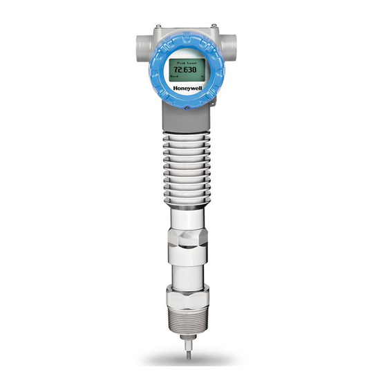
1 Introduction 1.1 Overview The SLG 700 Guided Wave Radar SmartLine transmitter is an electronic instrument designed to measure levels of liquid and solid materials. Guided Wave Radar (GWR) transmitters use time domain reflectometry with radar pulses guided by a metal probe and reflected off a product surface to determine levels in tanks. -
Page 18: Electronics Housing
These components are described below. Additional mounting and optional accessories are available, such as centering discs for probes. For list of all options and accessories please refer to the purchasing specifications, which is available, here: https://www.honeywellprocess.com/en- US/explore/products/instrumentation/process-level-sensors/Pages/smartline-level- transmitter.aspx. Figure 2-1: Components of the Level transmitter Electronics Housing The Electronics Housing contains these components. -
Page 19: Sensor Housing
Table 2-2: Available SmartLine GWR display characteristics Advanced 360° rotation in 90° increments Display Three configurable screen formats with configurable rotation timing Large process variable (PV) PV with bar graph PV with trend (1-999hrs, configurable) Echo stem plot for checking measurement accuracy ... -
Page 20: Probe
Probe The purpose of a Guided Wave Radar probe is to guide radar pulses produced by the radar transmitter towards the material being measured. It also guides the reflected pulse back to the transmitter for processing into a level measurement. The probe can be made of a single conductor such as for single wire or rod probes, or two conductors for coaxial probes. - Page 21 Foam (top of foam measurement) Foam (top of foam and liquid surface measurement) Coating/tacky liquids Crystallizing liquids Viscous liquids Probe is close to tank wall/disturbing objects (<12″/30cm) Probe could contact tank wall, nozzle or disturbing objects Turbulent Surface Turbulent fluid causing mechanical stress on probe Tall, narrow nozzles...
-
Page 22: Communicating With The Transmitter
1.4 Communicating with the Transmitter It is possible to remotely monitor and configure a transmitter using either the HART FOUNDATION Fieldbus (FF) protocols. Alternatively, with the HART option, the transmitter can be monitored using the analog current, and with both interfaces, can be configured using the three-button interface and display. -
Page 23: Figure 2-2: Example Of Hart Connection Rl
Scroll/search for file name: “HART Device Description (DD) files for Honeywell HART Devices” This .zip file contains the latest version of the DD files for all of Honeywell’s HART field devices. Unzip the file to locate the DD files applicable to the SLG 700 series. -
Page 24: Figure 2-3: Example Of Ff Connection
FOUNDATION Fieldbus (FF) The Honeywell SLG 700 is a SmartLine Level transmitter that has a wide range of additional features along with supporting the FOUNDATION Fieldbus (FF) communication protocol. The SLG 700 level transmitter with FF protocol provides a FOUNDATION Fieldbus interface to operate in a compatible distributed Fieldbus system. -
Page 25: Dtm-Based Tools And Experion
DTM-based tools and Experion HART and FOUNDATION Fieldbus models support Device Type Managers (DTMs) ® running on Field Device Technology (FDT) hosts such as PACTware or Field Device Manager (FDM) / Experion. The transmitter establishes communication with the host systems using DD or DTM. Device Description (DD) DD is a binary file that provides the definition for parameters in the FBAP of the transmitter. - Page 26 Enhanced Device Description (EDD) There are two types of EDDs are available, namely .ff5/.sy5 and .ffo/sym. The .ffo/.sym binary files are generated for the legacy hosts to load the device DD that is generated using latest tokenizer. Few constructs like Images that are supported in .ff5/.sy5 binaries, are not supported in .ffo/.sym binary files.
-
Page 27: Slg 700 Transmitter Nameplate
Figure 2-4: Example of a FF network 1.5 SLG 700 Transmitter nameplate The Transmitter nameplate is mounted on the top of the electronics housing (see Figure 2-5) and lists the following properties: Model number Physical configuration Power supply voltage ... -
Page 28: Figure 2-5: Transmitter Nameplate Example
CUSTOMER ID: User-defined identifier, if ordered, otherwise blank. HOUSING CONNECTION TYPE: Conduit fitting size: ½” NPT or M20 ASSEMBLED IN / MADE BY HONEYWELL: The country where the transmitter was assembled and tested. SIL INFORMATION: SIL 2/3 Capable is indicated if SIL certification applies, otherwise blank. -
Page 29: Transmitter Model Number Description
1.6 Transmitter Model Number Description The model number is comprised from a number of selections and options that can be specified when ordering the transmitter. It includes a basic transmitter type such as SLG720 (standard temperature, standard pressure) followed by a maximum of nine additional character strings that can be selected from a corresponding Table in the Model Selection Guide (MSG). -
Page 30: Security Considerations
The license key depends on the device ID which can be checked using the display (see Table 4-8 or DTM. It is possible to obtain new license keys for application types other than which the gauge was originally bought for by supplying the device ID to Honeywell and entering the newly obtained license key. -
Page 31: Radar Level Measurement
2 Radar Level Measurement 2.1 Overview This chapter describes the theory of operation of the transmitter and discusses how measurements are affected by tank and process conditions. 2.2 Theory of Operation Guided wave radar provides level measurement based on the Time-Domain Reflectometry (TDR) principle. -
Page 32: Figure 2-1: Gwr Measurement
Figure 2-1: GWR measurement = Dielectric Constant of Vapor Dielectric Constant of Level (Upper Product) Dielectric Constant of Interface (Lower Product) SLG 700 SmartLine Level Transmitter User’s Manual Page 16 Revision 8... -
Page 33: Tdr For Interface And Flooded Measurements
TDR for Interface and Flooded Measurements The Time-Domain Reflectometry (TDR) principle can also be used to measure an Interface Level as well as the upper level. The position of the level interface has to be calculated with knowledge of the dielectric constant (DC ) of the upper layer. -
Page 34: Signal Processing Configuration
The sensor is programmed with default values for all parameters, determined by the dielectric constants of the materials being measured. Either through the advanced display or using the Honeywell DTM (SLG 700 HART option manual 34-SL-25-06) these parameters can be adjusted to match the measurement conditions. Typically, the amplitude (also referred to as gain) of the model is the only parameter that needs to be adjusted, and this is generally only required if the dielectric constant of the medium is uncertain. -
Page 35: Amplitude Tracking
Figure 2-4 Radar Impulse Reflection model Although the algorithms are tolerant of signal amplitude variation, a good match is important to discern the true level signal from that caused by obstacles near the probe or secondary reflections. Both the DTM and the advanced display module show the signal quality, a measure of the match between radar pulse model and acquired echo curve. -
Page 36: Maximum Fill Rates, Latching And Timeouts
Maximum Fill Rates, Latching and Timeouts The maximum fill rate, also referred to as Rate of Change (ROC) limits the expected level changes between two successive measurements. Software revision prior to R200 allowed a range of 4 - 20 cm/s. As of R200 this limit is increased to 90 cm/s. If a level is detected to have moved further then the ROC limit, the level status is considered bad. -
Page 37: Signal Interferences And Background Echoes
The user needs to ensure that the level in the tank is below these values when acquiring the background. The field background is stored in permanent memory and can be displayed using the Honeywell DTM or DD. The obstacle suppression background can be used in place of the field background and is intended to both suppress process connector reflections as well as any false echoes generated by obstacles in the tank (ladders, pipes, valves) in the vicinity of the probe. -
Page 38: Accuracy And Measurement Range Specifications
The most recently updated background is also stored in permanent memory and is applied after a sensor reset if dynamic background is enabled. At all times the sensor maintains a copy of the original user-acquired (static) background echo and will revert to this if the dynamic background feature is once again disabled. -
Page 39: Figure 2-5: Upper Transition Zone Length And Minimum Blocking Distance High (Bdh) And Minimum Blocking Distance Low (Bdl) For Coax Probes In Water
Figure 2-5: Upper transition zone length and minimum blocking distance high (BDH) and minimum blocking distance low (BDL) for coax probes in water. Figure 2-6: Upper transition zone length and minimum blocking distance high (BDH) and minimum blocking distance low (BDL) for coax probes in oil. SLG 700 SmartLine Level Transmitter User’s Manual Revision 8 Page 23... -
Page 40: Figure 2-7: Transition Zone Lengths And Minimum Blocking Distance High (Bdh) For Single Lead Probes In Water
Figure 2-7: Transition zone lengths and minimum blocking distance high (BDH) for single lead probes in water. SLG 700 SmartLine Level Transmitter User’s Manual Page 24 Revision 8... -
Page 41: Figure 2-8: Transition Zone Lengths And Minimum Blocking Distance High (Bdh) For Single Lead (I.e. Rod And Rope) Probes In Oil
Figure 2-8: Transition zone lengths and minimum blocking distance high (BDH) for single lead (i.e. rod and rope) probes in oil. Figure 2-9 Minimum blocking distances, steam application for a threaded HTHP process connector SLG 700 SmartLine Level Transmitter User’s Manual Revision 8 Page 25... -
Page 42: Figure 2-10 Minimum Blocking Distance, Steam Application For A Flanged Hthp Process Connector
Note: BDH depends on threaded or flanged. Rods are either 30 or 50 cm. See Error! Reference source not found. Figure 2-10 Minimum blocking distance, steam application for a flanged HTHP process connector Table 2-1: Blocking Distance High Process Saturated Steam Minimum BDH Min dist to inlet or surface connector type... - Page 43 15 cm or if the measurement of thin interfaces is inaccurate, it might be necessary to adjust the reflection models using the Honeywell DTM. Refer to the SLG 700 HART Option manual, #34-SL-25-06 for details on adjusting model parameters.
-
Page 44: Process Applications
2.5 Process Applications The SLG 700 Level transmitter is designed to work with a wide range of process conditions. The sensor offers a total of 5 application modes: Single Liquid Two Liquids, flooded (only interface between to liquids is measured) ... -
Page 45: Figure 2-12: Two-Liquids Non-Flooded
Figure 2-12: Two-liquids non-flooded. Two-liquid non-flooded application type is used in cases such as water beneath a hydrocarbon in a separation tank. Both the top level and interface must be measured. The low-DC material is assumed to be on top of the higher DC material. As of R200 this application type is a pay-for-feature option;... -
Page 46: Low Dielectric Applications
15cm or if the measurement of thin interfaces is inaccurate, it might be necessary to adjust the reflection models using the Honeywell DTM. Refer to the SLG 700 HART Option manual, #34-SL-25-06 for details on adjusting model parameters. -
Page 47: Steam Boiler Applications
Usually, it will be the material absorption which determines the depth under which the end of probe will be visible. This can be difficult to predict as published tables might not be correct especially if there are material impurities or absorbed water present. Steam Boiler Applications Sensor revision R200 introduced a new application type: the measurement of the water level in high-pressure steam boilers. -
Page 48: Process Condition Considerations
2.6 Process Condition Considerations Process conditions can affect the way the surface appears to the GWR Transmitter. Turbulence Turbulence can result in the following measurement issues: The height of the surface reflection appears smaller. The level measurements display higher variability. In extreme cases of turbulence, the surface level measurement can be lost entirely. -
Page 49: Container Considerations
2.7 Container Considerations Shapes The SLG 700 transmitter may be used in any shape of container. In general, it is designed to be mounted vertically on top of the container, although angled mounting is also possible. See section 3.2.6 for angled mounting limitations. Figure 2-14: Top vertical and angled mounting Materials (plastic vs. -
Page 50: Blocking Distance High And Blocking Distance Low Guidance
2.8 Blocking distance high and blocking distance low guidance The minimum blocking distances and accuracy in the transition zones may be compromised in certain applications. In these cases and in order to meet the required specifications, it is necessary to follow the guidance provided below. If the sensor performances in the transition and blocking zones are compromised due to the presence of an obstruction and if the performances cannot be improved, it is advisable to increase the configured blocking distances accordingly. - Page 51 It is possible for the level to rapidly leave a blocking zone and exceed the maximum fill rate. Note that the 'maximum fill rate' is the user-set maximum rate at which the level can change which will be reported before a digital flag will be set. As discussed in 2.3.3, when the maximum fill rate is exceeded, the transmitter considers the level lost and the gauge initiates the echo lost timeout counter...
-
Page 52: Transmitter Installation
Connect transmitter wiring and power. After Installation check the transmitter’s configuration and tune if necessary. Transmitters that were ordered using Honeywell’s SmartLine Application and Validation Tool (AVT) will come with parameters pre-loaded so that the transmitter will give accurate level measurements out-of-the-box. -
Page 53: Tools
Tools Required tools depend on options ordered. For this item Use this tool (Model number signifiers) M3 set screw for Coaxial coupler (SCA ACA) 1.5 mm Allen key M4 set screw for Electronics Housing rotation AF 2.0 mm Allen key M5 set screw for Wire probe end weight (SWA, AF 2.5 mm Allen key SWB) -
Page 54: Mechanical Installation
3.2 Mechanical Installation Follow the steps in Table 3-2. See Section 3.3.1 for wiring and configuration steps. Table 3-2: Mechanical installation sequence Step Action See Section Check probe dimensions and strength. 3.2.1 Trim probe to correct length. 3.2.3 Attach/assemble the probe to the process connector. 3.2.4 Attach centering disk to probe if applicable. -
Page 55: Table 3-3: Sensor Details - All Models
Table 3-3: Sensor Details – All Models Parameter Description Probe Type Min / Max Length Materials 0.4m (1.3ft) / 6.3m (20.7ft) SS 3161L, C-276* Wire 1.0m (3.3ft) / 50m (164 ft) SS 316 Coax 0.4m (1.3ft) / 6.3m (20.7ft) SS 3161L, C-276* *Only for model SLG720 Table 3-4: Minimum blocking distances and transition zones for the various probe types. -
Page 56: Figure 3-1 Slg720 Probe Dimensions, Mm [In]
Figure 3-1 SLG720 probe dimensions, mm [in] SLG 700 SmartLine Level Transmitter User’s Manual Page 40 Revision 8... -
Page 57: Figure 3-2: Slg720 Fep Probe Dimensions, Mm [In]
Figure 3-2: SLG720 FEP probe dimensions, mm [in] SLG 700 SmartLine Level Transmitter User’s Manual Revision 8 Page 41... -
Page 58: Figure 3-3: Slg726 Threaded Process Connection Probe Dimensions; Mm [In]
Figure 3-3: SLG726 Threaded process connection probe dimensions; mm [in] SLG 700 SmartLine Level Transmitter User’s Manual Page 42 Revision 8... -
Page 59: Figure 3-4 Slg726 Flanged Process Connection Probe Dimensions; Mm [In]
Figure 3-4 SLG726 Flanged process connection probe dimensions; mm [in] SLG 700 SmartLine Level Transmitter User’s Manual Revision 8 Page 43... -
Page 60: Figure 3-5: Slg726 Saturated Steam Application Threaded Process Connection Probe Dimensions; Mm [In]
Figure 3-5: SLG726 Saturated steam application threaded process connection probe dimensions; mm [in] Figure 3-6: SLG726 Saturated steam application flanged process connection probe dimensions; mm [in] SLG 700 SmartLine Level Transmitter User’s Manual Page 44 Revision 8... -
Page 61: Table 3-7: Tensile Load Limits For Flexible Probe
Tensile load Motion of the medium inside of the tank will impart load onto the probe of the transmitter. Flexible wire probes will experience tensile loading that will be transferred to the roof of the tank. Ensure that the maximum probe tensile load does not exceed maximum tank roof load. Depending on position, forces on anchored flexible probes can be two to ten times greater than that of flexible probes with end weights. - Page 62 Probe Maximum Bending Model Selection Probe description Torque [Nm]* SLG720 Coax 22mm, 2m (6′) segments SLG726 Coax 42mm, 2m (6′) segments *For an angle mounted probe reduce these limits by 50% to allow for bending from gravity. To calculate your probe’s torque due to fluid motion use the following formula and check it against the torque limits in Table 3-9 Table...
-
Page 63: Trim The Probe Length
Shortening a SLG720 coaxial probe Note: The coaxial probe trimming instruction applicable only to SLG720. For SLG726, if a coaxial probe is not the specified length, contact Honeywell’s Technical Assistance Center as a new probe could be required / ordered. -
Page 64: Attach/Assemble The Probe
Technical Assistance Center (TAC): 800-822-7673 in North America or 1-602-313-5558 from the rest of the world. Step Action Coaxial probe consists of inner rod and coaxial outer tube. To trim the coaxial probe, both inner rod and coaxial outer tube need to be trimmed. For trimming the inner rod, refer to rod probe trimming instruction detailed above. -
Page 65: Figure 3-9: Rod Probe Assembly
Rod probe assembly Rod probes are shipped in segments. The segments are attached to each other with a stud and a lock washer. Step Action Fully thread the nut onto the central conductor. Using a lock washer, thread the first rod segment on to the central conductor. Torque the nut against rod probe and lock washer to secure the connection. -
Page 66: Figure 3-10: Slg726 Flanged Process Connection, Probe Nut Installation Position, Mm [In]
Figure 3-10: SLG726 flanged process connection, probe nut installation position, mm [in] Wire probe assembly Wire probes can be supplied with an optional end weight. Step Action Fully thread the nut onto the central conductor. Using a lock washer, thread the wire swage on to the central conductor. -
Page 67: Figure 3-11: Wire Probe Assembly
Process Connector Lock Washer Rope Probe Central Connector Set Screws End Weight Figure 3-11: Wire probe assembly Coaxial probe assembly The coaxial probe consists of an inner rod conductor, surrounded by an outer tube shield. The concentricity of the inner rod inside of the outer tube is maintained by spacers placed along the probe length. -
Page 68: Figure 3-13: Slg720 Coaxial Probe Assembly (Single Outer Tube Depicted)
SLG720 The inner rod is comprised of 1.0m rod segments and one rod end. Depending on the length of the probe there may be 0 to 6 1.0m rod segments. As with the rod probe, the rod segments are attached to each other by way of a stud and lock washer, see Figure 3-13: SLG720 Coaxial probe assembly (single outer tube depicted). - Page 69 Probe Length 1.0m to 2.0m Step Action Fully thread the nut onto the central conductor of the process connector. Place a lock washer between the locknut and the first rod segment and torque the nut against the rod segment and lock washer to secure the connection. Note: Tighten rod connection point to the following torque: ...
-
Page 70: Figure 3-12: Slg720 Coaxial Probe Assembly (Single Outer Tube Depicted)
Figure 3-12: SLG720 Coaxial probe assembly (single outer tube depicted) Figure 3-13: SLG720 Coaxial probe assembly (single outer tube depicted) SLG 700 SmartLine Level Transmitter User’s Manual Page 54 Revision 8... - Page 71 SLG 700 SmartLine Level Transmitter User’s Manual Revision 8 Page 55...
- Page 72 SLG726 The inner rod is comprised of 2.0m rod segments and one rod end. Depending on the length of the probe there may be 0 to 3 2.0m rod segments. As with the rod probe, the rod segments are attached to each other by way of a stud and lock washer. In the coaxial probe construction, a spacer is placed at each joint, retained by the lock washer.
- Page 73 ≤ 2.0m Probe Length Step Action Thread the nut onto the central conductor of the process connector. Refer to Figure 3-10: SLG726 flanged process connection, probe nut installation position, mm [in] for nut position on flanged process connectors. Place a lock washer between the locknut and the first rod segment.
- Page 74 Depending on probe length there may be 0 to 2 coaxial outer tube "extension" segments and 1 coaxial tube "end" segment. Slip the next coaxial tube "extension" segment over the last rod segment and spacer and tighten to the coaxial coupler. Note: Tighten connection point to the following torque: ...
-
Page 75: Figure 3-14: Slg726 Coaxial Probe Assembly
Figure 3-14: SLG726 Coaxial probe assembly (Segmented outer tube depicted) Saturated Steam Application Probe Assembly Saturated steam application is available with SLG726 rod and coax probes. The nut and first inner rod segment have a larger diameter. The remaining hardware is identical. Refer to Error! Reference source not found. -
Page 76: Figure 3-15 Saturated Steam Application Rod Probe Assembly
Figure 3-15 Saturated steam application rod probe assembly Saturated steam hardware Figure 3-16: Saturated steam application coaxial probe assembly SLG 700 SmartLine Level Transmitter User’s Manual Page 60 Revision 8... -
Page 77: Centering Disks And Configured Probe Length
When this option is selected the transmitter will be supplied with a nut and lock washer, but no probe. Recommended probe diameter and material of construction are shown in Table 3-11. When the no-probe option is selected, Honeywell does not guarantee transmitter performance. Table 3-11: Recommended probe diameter and material of construction... - Page 78 Note: SLG720: One 3.5mm hole to be drilled into the end of the rod probe using a supplied drilling jig once the probe has been cut to length (if required). SLG720 PTFE application: No hole required. Error! Reference source not found.. SLG726: Require two 3.5mm holes.
-
Page 79: Figure 3-17: Recommended Location Of Holes For Rod Probes
Figure 3-17: Recommended location of holes for rod probes SLG 700 SmartLine Level Transmitter User’s Manual Revision 8 Page 63... -
Page 80: Figure 3-18: Centering Disks For Wire And Rod Probes
Figure 3-18: Centering disks for wire and rod probes. Note: for Rod probe the cotter pin is placed underneath the disk and the washer to hold them in place. Figure 3-19: Centering disks for FEP coated wire and rod probes SLG 700 SmartLine Level Transmitter User’s Manual Page 64 Revision 8... -
Page 81: Table 3-12: Centering Disk Determination From Pipe Size And Schedule
Table 3-12: Centering disk determination from pipe size and schedule Pipe schedule Pipe size 5s,5 10s,10 40s,40 80s,80 2“ 2” 2” 2” 2” 3” 3” 3” 3” 3” 4” 4” 4” 4” 4” 4” 3” 5” 4” 4” 4” 4” 4”... -
Page 82: Table 3-14: Probe Length For Different Probe Types
When a centering disk is added to a rod probe, a new probe length must be measured and configured in the transmitter. Failure to adjust the probe length and the probe termination configurations may lead to inaccurate readings close to the end of probe or/and may require the user to increase the blocking distance low. -
Page 83: Mounting The Transmitter
Figure 3-20: Probe length definition for rod probes using a centering disk Mounting the transmitter In the following dimension figures, “R” denotes the transmitter reference plane. SLG720 Transmitter dimensions Figure 3-21: Flanged SLG720 Transmitter, mm [in] SLG 700 SmartLine Level Transmitter User’s Manual Revision 8 Page 67... -
Page 84: Figure 3-22: Threaded (Npt ¾", 1", 1½", 2") Slg720 Transmitter, Mm [In]
Figure 3-22: Threaded (NPT ¾", 1", 1½", 2") SLG720 Transmitter, mm [in] SLG 700 SmartLine Level Transmitter User’s Manual Page 68 Revision 8... -
Page 85: Figure 3-23: Threaded (Bsp/G ¾", 1", 1½") Slg720 Transmitter, Mm [In]
Figure 3-23: Threaded (BSP/G ¾”, 1”, 1½”) SLG720 Transmitter, mm [in] SLG 700 SmartLine Level Transmitter User’s Manual Revision 8 Page 69... -
Page 86: Figure 3-24: Flanged Slg726 Transmitter, Mm [In]
SLG726 Transmitter dimensions Figure 3-24: Flanged SLG726 transmitter, mm [in] SLG 700 SmartLine Level Transmitter User’s Manual Page 70 Revision 8... -
Page 87: Figure 3-25: Threaded (Npt 1½", 2") Slg726 Transmitter, Mm [In]
Figure 3-25: Threaded (NPT 1½", 2”) SLG726 transmitter, mm [in] SLG 700 SmartLine Level Transmitter User’s Manual Revision 8 Page 71... -
Page 88: Figure 3-26: Threaded (Bsp/G 1½") Slg726 Transmitter, Mm [In]
Figure 3-26: Threaded (BSP/G 1½") SLG726 transmitter, mm [in] SLG 700 SmartLine Level Transmitter User’s Manual Page 72 Revision 8... -
Page 89: Suitable Mounting Position
Suitable mounting position To minimize signal interference, observe the minimum distances in Table 3-15. Examples of obstacles to avoid are protruding welds, internal installations, agitators, pipes and nozzles extending into the container, heating coils, inlet streams, ladders, etc. Metallic objects are a source of bigger interferences than non-metallic objects. Turbulent applications may require the probe to be anchored to prevent it from contacting or getting too close to container walls or obstacles. -
Page 90: Optimum Operating Temperature
Backgrounds can be taken using the Honeywell DTM, the local display, or the supported handhelds. The DTM instructions can be found in the SLG 700 HART option manual 34-SL-25-06. -
Page 91: Temperature Requirements
Temperature requirements Thermal loading from the process and ambient environment affects the temperatures of the electronics, as well as the seals inside the level transmitter. Figure 3-28: SLG720 temperature limitsdefines the limits of ambient and process temperatures as they pertain to specific seal materials in the transmitter. -
Page 92: Figure 3-29: Slg726 Temperature Limits
Figure 3-29: SLG726 temperature limits Figure 3-30: SLG726 Maximum pressure based on maximum operating temperature SLG 700 SmartLine Level Transmitter User’s Manual Page 76 Revision 8... -
Page 93: Table 3-16: Slg726 Maximum Pressure Based On Maximum Operating Temperature In Tabular Form
Table 3-16: SLG726 Maximum pressure based on maximum operating temperature in tabular form AMBIENT TEMPERATURE [ MAX PRESSURE [bar] INTRINSICALLY SAFE (IS) NON-(IS) SLG 700 SmartLine Level Transmitter User’s Manual Revision 8 Page 77... -
Page 94: Figure 3-31: Flanged Tank Connection
Flange mount To mount a flanged transmitter, bolt the transmitter’s flange to the flange on the tank. Step Action On insulated tanks, remove enough insulation to accommodate the flange extension. Note: It is the End User’s responsibility to provide a flange gasket and mounting hardware that are suitable for the transmitter’s service condition. -
Page 95: Figure 3-32: Flange Mounting
In certain applications, taller nozzles may be accommodated but near zone performance at the exit of the nozzle may be reduced. For nozzle dimensions that do not meet the requirements outlined in Table 3-17 contact the Honeywell Technical Assistance Center. SLG 700 SmartLine Level Transmitter User’s Manual Revision 8 Page 79... -
Page 96: Figure 3-33: Oversized Nozzle Configuration
Area Organization Phone Number United States and 1-800-343-0228 Customer Service Honeywell Inc. Canada 1-800-423-9883 Global Technical Support Global Email Honeywell Process hfs-tac-support@honeywell.com Support Solutions For single lead probes, avoid nozzles > 8" (200 mm) in diameter nozzles, particularly when measuring low dielectric constant materials. The user will need to install a smaller inner nozzle when operation with these larger nozzle diameter required, see Figure 3-33: Oversized nozzle configurationfor inner nozzle design requirements. -
Page 97: Figure 3-34: Threaded Tank Connection
Threaded mount Transmitters with threaded process connectors can be screwed to tanks or nozzles with threaded bosses. For tanks with BSP/G threads, place a gasket on top of the tank, or use a sealant on the threads of the tank connection. Figure 3-34: Threaded tank connection Figure 3-35: Tank roof mounting using threaded connection SLG 700 SmartLine Level Transmitter User’s Manual... -
Page 98: Figure 3-36: Bypass Installation
Mounting on a bypass / bridle SLG 700 transmitter can be successfully installed in a new or existing bypass pipe, bridle, or a side pipe as shown Figure 3-36: Bypass installation. This type of installation is often simpler and allows the addition of radar level measurement to an otherwise busy installation. -
Page 99: Mounting On A Non-Metallic Container
Coaxial probe 1.5” (37.5mm) Table 3-19: SLG726 bypass and stillwell recommended diameters Probe type Recommended diameter Minimum diameter 3” or 4” (75mm or 100mm) 2” (50mm) Rod probe 4” (100mm) 2” (50mm) Wire probe 2” (50mm) Coaxial probe Chambers with smaller diameter can lead to problems with build-up. Chambers larger than 6"... -
Page 100: Figure 3-38: Mounting In Concrete Silos
Figure 3-38 depicts an example of mounting in concrete silos, the placement of the concrete versus the metal sheet used to secure the transmitter. Both Figure 3-37 and Figure 3-38 are considered non-metallic mounts. Both types of mountings are subject to the same specifications. -
Page 101: Figure 3-39: Remote Mount
Figure 3-39: Remote mount SLG 700 SmartLine Level Transmitter User’s Manual Revision 8 Page 85... -
Page 102: Rotate Transmitter Housing
Rotate transmitter housing WARNING: Rotating the electronics housing with respect to the sensor housing may damage the sensor electronics. Once installed, the transmitter housing can be rotated to the desired orientation by loosening the two setscrews on the sensor housing and then rotating the sensor electronics with respect to the process connector. -
Page 103: Figure 3-41: Anchoring Wire Probes
Figure 3-41: Anchoring wire probes When anchoring, a wire probe it is recommended that the wire be slack to prevent excessive tensile loading from motion of medium and/or thermal expansion. The sag should be ~1cm/m (1.5″/10′) of the probe length. See Figure 3-42. -
Page 104: Figure 3-43: Anchoring Coaxial Probes
Coaxial probes can be anchored along their length. Ensure that the probe can move freely along its length to allow for thermal expansion. Thermal coefficient of expansion = 16 × 10 m/m-°K Coaxial probes can be guided by a tube welded to the bottom of a tank. Make sure that the coaxial probe can move freely to allow for thermal expansion. -
Page 105: Install Conduit Entry Plugs And Adapters
Install conduit entry plugs and adapters NOTICE THE CONDUIT/CABLE GLAND ENTRIES OF THIS PRODUCT ARE SUPPLIED WITH PLASTIC DUST CAPS WHICH ARE NOT TO BE USED IN SERVICE. IT IS THE USER’S RESPONSIBILITY TO REPLACE THE DUST CAPS WITH CABLE GLANDS, ADAPTORS AND/OR BLANKING PLUGS WHICH ARE SUITABLE FOR THE ENVIRONMENT INTO WHICH THIS PRODUCT WILL BE INSTALLED. -
Page 106: Flange Pressure Ratings
Flange pressure ratings ANSI: 316/316L Flanges according to ANSI B16.5 SLG720: Max. 200 C/40 bar (392 F/580 psig). SLG726: Up to Class 1500. C276 > 316L Flanges according to ANSI B16.5 SLG720: Max. 200 C/40 bar (392 F/580 psig) 316/316L Flanges according to EN 1092-1, material group 14E0. SLG720: Max. -
Page 107: Electrical Installation
3.3 Electrical Installation Wiring a transmitter The transmitter is designed to operate in a two-wire power/current loop with loop resistance and power supply voltage within the operating range shown in Figure 3-44. HART / 4-20mA Voltage Operating Ranges Supply Voltage Max. - Page 108 Consideration is required when selecting intrinsic safety barriers to ensure that they will ), including the required 250 Ω of supply at least minimum Transmitter voltage (V XMTR MIN resistance (typically within the barriers) needed for digital communications. Transmitter loop parameters are as follows: = maximum loop resistance (including barriers and wiring) that will allow LOOP MAX proper Transmitter operation and is calculated as...
-
Page 109: Terminal Connections
Loop current wiring should never be connected to the TEST “+” terminal. This can damage the Transmitter. Additionally, never connect the current measurement device between the Loop “+” terminal and the TEST “+”terminal. This also will damage the Transmitter. Terminal Connections Figure 3-45: HART 3-Screw Terminal Board and Grounding Screw A FOUNDATION Fieldbus terminal block has a 2-screw terminal board, The Test+ terminal is not present. -
Page 110: Foundation Fieldbus
FOUNDATION Fieldbus FOUNDATION Fieldbus transmitters require a terminal voltage of 9.0V to 32.0V. See page for intrinsically safe and FISCO parameters. Wiring Procedure Ensure the loop power supply is off. Figure 3-45 for parts locations. Loosen the end cap lock using a 1.5mm Allen wrench. -
Page 111: Lightning Protection
Lightning Protection If your Transmitter includes the optional lightning protection, connect a wire from the Earth Ground Clamp (see Figure 3-45) to Earth Ground as short as possible to make the protection effective. Use a size 8AWG or (8.37mm ) bare or green covered wire for this connection. -
Page 112: Operating The Transmitter
(or in instances where the display is difficult to reach) or configuration use one of the following interfaces. DTM or DD – HART and FF There are two ways an external user interface can be connected to a Honeywell transmitter: Device Description (DD) files ... -
Page 113: Three-Button Operation
4.2 Three-Button Operation The SLG 700 optional three-button interface provides a user interface and operation capability without exposing the transmitter electronics. Figure 4-1 shows the location of the three-button option and the labels for each button. The buttons are accessible by loosening the rightmost screw and rotating the covering nameplate. -
Page 114: Figure 4-1: Three-Button Option
Figure 4-1: Three-Button Option SLG 700 SmartLine Level Transmitter User’s Manual Page 98 Revision 8... -
Page 115: Menu Navigation
Table 4-1: Three-Button Option Functions Physical Advanced Action Button Display Scroll to previous menu item in an active list. Increment Left Scroll through alphanumeric list to desired character (ex. Move cursor Up for entering Tag names or numeric values) Scroll to next menu item in an active list. -
Page 116: Editing A Numeric Value
Table 4-2: Three-Button Data Entry Screen Numeric data entry Text entry Symbol Display the high limit for this parameter. ▲ Not Available This symbol only appears in the left-most position of the data entry field. Display the low limit for this parameter. ▼... -
Page 117: The Advanced Display Menu
4.3 The Advanced Display Menu Table 4-3 shows the top 3 levels of the Advanced Display menus. At each level is a <Return> that lets you return to the previous level. Table 4-3: Advanced Display Main Menu Structure Level 1 Level 2 Level 3 <Exit>... -
Page 118: Correlation Model Recalculation
Correlation Model Recalculation Information on what triggers a correlation model recalculation is summarized in the table below. Table 4-4: Correlation Model Recalculation Parameter recalculated Parameters that will trigger recalculation / reset required Surface Model Gain Vapor DC, Upper DC, Lower DC, Application Type, Probe Type, Transmitter Model, Mounting Location, Sensor Connection Type, Mounting Diameter... -
Page 119: Table 4-5: Display Config Sub-Menu
Table 4-5: Display Config sub-menu This table describes the Advanced Display menu’s “Display Config” sub-menu. <Return> Return to the Level 1 menu Level 2 Level 3 Description Action <Return> Press to enter Set Contrast Adjust the LCD contrast level. menu selection ... - Page 120 Display Config” sub-menu, continued .. <Return> Screen Format None Select the Screen (FF read only) format from the list. PV & Bar Graph PV & Trend Trend Hours Select the amount of (FF read only) historic data visible on the Trend screen. Range: 1 to 999 hours.
-
Page 121: Table 4-6: Basic Configuration Sub-Menu
Press to enter Disp High Limit ######### Enter the upper limit (FF read only) shown on the Bar menu selection Graph or Trend and to select screen. number. to enter and shift Disp Low Limit ######### Enter the lower limit (FF read only) shown on the Bar... - Page 122 <Return> Single Liquid Select the Measured Product from the List 2 Liq Flooded Measured Prod 2 Liq NonFlood Saturated Steam SingleLiqLowDC Press to Applicable for single and enter two liquids, non-flooded menu only. If its value greater Vapor DC selection, than UP/LP DC Warning ...
- Page 123 Upr Prod Thick Lower Prod Vol Upper Prod Vol <Return> #####.### Damping ##.# Disabled: Sets loop output and burnout levels to Honeywell levels. NAMUR Output Disabled Enabled: Sets loop output and burnout levels to the NAMUR Enabled Press to...
- Page 124 <Return> Press to Year # # # # Enter the current year. enter menu selection, Year will only be and to visible if no Install Date has been select number, to written to the transmitter. enter and shift to next digit Press ...
-
Page 125: Table 4-7: Advanced Config Sub-Menu
Table 4-7: Advanced Config sub-menu This table describes the Advanced Display menu’s “Advance Config” sub-menu. Advanced configuration is described in detail in the SLG 700 HART Option manual, #34-SL-25-06. <Return> Return to the Level 1 menu Level 3 Description Action Level 2 <Return>... - Page 126 Backgrnd Type Field Background type to capture. Obstacle Use Level Use level instead of distance to surface for Obstacle capture (Obstacle Backgrnd Backgrnd length entered at time of capture. Type only) Capture Start Capture Begins a field background capture process, with progress (capture process is (Measured indicated by bar graph on line...
- Page 127 <Return> Probe Start Cal Begins a probe length Length Cal calibration, with progress (calibration process Press ↵ to (SingleLiqLo indicated by bar graph on is inactive) select action line immediately above. Measured Prod only) Stop Cal Cancels the currently active probe length (calibration process calibration process.
- Page 128 <Return> Enabled Ampl Tracking Improved level tracking for Disabled difficult conditions or uncertain medium Press to enter attenuation. menu selection. Process Conn Location Reflection model location and to select Surface from list. to Interface enter. Probe End Reflectn Model Saturated Steam Press ...
- Page 129 Press to enter menu Set DAC Output This selection allows you to force the DAC output to any value between 3.8 and 20.8mA. selection Scroll to Set DAC Loop Test Normal Note: This selection will put the DAC into (HART only) Fixed Output Mode.
-
Page 130: Table 4-8: Monitor Sub-Menu
Table 4-8: Monitor sub-menu This table describes the Advanced Display menu’s “Monitor” sub-menu. All items are Read- Only. Refer to troubleshooting for resolutions. <Return> Return to the Level 1 menu Level 2 Level 3 Status Description <Return> Active Diags (R) Sensor Module (R) FAULT: There is a problem with the Sensor. - Page 131 Low Power Mode (R) Yes: Sensor is in low power mode Reflectn Ref Loc (R) FAULT: Reflection reference cannot be located FAULT Ref Plane Offset (R) FAULT: Reference plane offset is invalid FAULT Unlic Intf Meas (R) FAULT: Unlicensed Interface measurement FAULT option Unlic Sat Steam (R)
- Page 132 <Return> Active Diags (R) Shows the number of Non-Critical Diagnostics that are currently active Supply Voltage (R) LOW: Supply voltage is below the low specification limit HIGH: Supply voltage is above the high HIGH specification limit. Elec Module Temp OVERTEMP: Electronics temperature is outside the operating range (-40°C to +85°C).
- Page 133 Surface Sgnl Str (R) Good Bad: Signal Strength is bad Surfac Sgnl Qlty (R) Good Bad: Signal Quality is bad Interfc Sgnl Str (R) Good Applicable for Two Liquid Products Bad: Signal Strength is bad Interfc Sgnl Qlty (R) Good Applicable for Two Liquid Products Bad: Signal Quality is bad This is a roll-up status that is set when any...
- Page 134 <Return> Measurd Prod Lvl Non-linearized HART only. product level If linearization is disabled then Product Level and Measurd Prod Lvl will be same. Surface Sgnl Str Surface Signal strength depends on a function of distance and the medium. As the level and Signal Strength interface peaks are negative, a more Interfc Sgnl Str (R)
- Page 135 <Return> Duration Duration of echo stem plot 0 to 3600 Displays the echo stem plot for the selected Duration. Use this display to check that the radar pulse is measuring accurately. Example: Echo stem plot for 2 liquid interface: Show Stem Plot X axis: The Reference plane is at 0.
-
Page 136: Monitoring The Advanced Display
4.4 Monitoring the Advanced Display This section describes the information shown on the operator screens of the Advanced Display. Advanced Displays As shown in Figure 4-2, the Advanced Display provides three formats. Table 4-9 lists and describes the fields in each of the three Advanced Display formats. Essentially, all three formats provide the same information, but with the following differences: ... -
Page 137: Table 4-9: Advanced Displays With Pv Format Display Indications
Table 4-9: Advanced Displays with PV Format Display Indications Display Indicator Description Diagnostic Diagnostic condition present This indicator is displayed any time a diagnostic is present in the transmitter, either Critical or Non-Critical. To determine which Non-Critical diagnostics are active, use the local buttons to call up the Non-Critical diagnostics menu. -
Page 138: Button Operation During Monitoring
Display Indicator Description PV Status Good: The transmitter is operating normally Bad: The transmitter has detected a critical fault condition. The PV Status field will flash when this condition is present and the PV Value will be displayed on a black background as follows: Warning: When the status field indicates a Bad status, the displayed PV value will represent the last known good value or will be set to 0 if the last known good value does not exist. -
Page 139: Changing The Failsafe Direction And Write Protect Jumpers (Including Simulation Mode)
4.5 Changing the Failsafe Direction and Write Protect Jumpers (Including Simulation mode) HART Transmitters are shipped preconfigured with a set failsafe direction (table V, character 4 of the model number). Upscale Failsafe means that the Transmitter output will set the HART current output to upscale failsafe (maximum output) upon detection of a critical status. -
Page 140: Figure 4-3: Locating The Failsafe And Write Protect Jumpers
Set each jumper to the desired position (UP/OFF or DOWN/ON). See Table 4-10 and Table 4-11. If applicable, re-install the Display module as follows: • Orient the display as required. • Install the Interface Connector in the Display module such that it will mate with the socket for the display in the Communication module. -
Page 141: Table 4-10: Hart Failsafe And Write Protect Jumpers
Table 4-10: HART Failsafe and Write Protect Jumpers Jumper Description Arrangements Failsafe = UP (High) Write Protect = OFF (Not Protected) Failsafe = DOWN (Low) Write Protect = OFF (Not Protected) Failsafe = UP (High) Write Protect = ON (Protected) Failsafe = DOWN (Low) Write Protect = On (Protected) Table 4-11: FOUNDATION Fieldbus Simulation and Write Protect Jumpers... -
Page 142: Maintenance
5 Maintenance 5.1 Overview The design of the transmitter uses electromagnetic impulses guided along a metallic probe and time domain reflectometry to measure distance to measured material and convert it into level indication. Because there are no moving parts, the maintenance of the transmitter is greatly reduced in comparison with historic level measurement devices. - Page 143 SLG 700 SmartLine Level Transmitter User’s Manual Revision 8 Page 127...
- Page 144 SLG 700 SmartLine Level Transmitter User’s Manual Page 128 Revision 8...
-
Page 145: Procedures
5.3 Procedures Output Check Procedures The Output Check has the following procedures: The Loop Test procedure checks for continuity and the condition of components in the output current loop. The Trim DAC Current procedure calibrates the output of the Digital-to-Analog converter for minimum (0%) and maximum (100%) values of 4 mA and 20 mA, respectively. -
Page 146: Constant Current Source Mode Procedure
Constant Current Source Mode Procedure Figure 5-1: Current Loop Test Connections 1. Refer to Figure 5-1 for test connections. Verify the integrity of electrical components in the output current loop. 2. Establish communication with the Transmitter. For these procedures, the values of components in the current loop are not critical if they support reliable communication between the Transmitter and the Toolkit. -
Page 147: Replacing The Terminal Block
6. Select the Set button. A box will be displayed asking Are you sure you want to place the transmitter in output mode? With the Transmitter in Analog mode, you can observe the output on an externally- connected meter or on a local meter. 7. -
Page 148: How To Replace The Sensor Housing
5.4 How to replace the Sensor Housing The Sensor Housing contains the ribbon cable that allows the Electronic Housing to gather data from the probe. Figure 5-3: Sensor Housing WARNING: The Sensor Housing is attached to the Electronic Housing using a threaded connection. - Page 149 Unplug the ribbon cable from the Communication Module. Do not discard any of the parts. Carefully unscrew the Sensor Housing from the Electronics Housing. Manually keep turning the ribbon cable to ensure the ribbon cable is not damaged or pinched. There is an o-ring on the top of the Sensor Housing.
-
Page 150: Tools Required
Tools required. WARNING: When installed as explosion-proof or flame-proof in a hazardous location, keep covers tight while the transmitter is energized. Disconnect power to the transmitter in the non-hazardous area prior to removing end caps for service. When installed as non-incendive or non-sparking equipment, disconnect power to the transmitter in the non-hazardous area, or determine that the location is non-hazardous before disconnecting or connecting the transmitter wires. -
Page 151: Figure 5-6: Location Of Sensor Housing And Attachment Set Screws
assembly 2. Remove power from transmitter. 3. If a new terminal assembly is also being installed follow instructions 34-ST-33-64. The relevant part numbers are listed in Table 7-1. GWR Level Terminator Module w/Lightning Protection Kit 50095191-502 for HART Modules GWR Level Terminator Module w/Lightning Protection Kit 50095191-510 for FF Modules GWR Level Terminator Module w/o Lightning Protection Kit... -
Page 152: Figure 5-7: Communications Housing Assembly
6. Loosen the end cap locking screw and unscrew the end cap on the Communications Electronics side of the transmitter communications housing. Figure 5-7: Communications Housing Assembly 7. If equipped with a Display Module, carefully depress the two tabs on the sides of the Display Module, and pull it off. -
Page 153: Figure 5-8: Rook Assembly
Figure 5-8: Rook Assembly WARNING: Do not tightly screw together the Sensor Housing into the Electronics Housing. The connection should be to the point where the o- ring is not visible. Tighten set screw as shown in Figure 5-8. The set-screw should not protrude from the Communications electronics housing. -
Page 154: Figure 5-9: - Sensor Ribbon Cable
Figure 5-9: - Sensor ribbon cable Note: Sensor ribbon cable wire aligns with pin 1 of J4 as shown. The Communication Module is then rotated 180 degrees to seat in Communications Housing. Carefully, insert the Communication Module into the Electronics housing compartment. Ensure that the Sensor Ribbon Cable is not pinched. -
Page 155: Figure 5-10: Location Of Rf-Connector At Bottom Of Sensor Housing
Apply O-ring lubricant to the end cap o-ring before installing the end cap. Reinstall the end cap and tighten the end cap locking screw. Ensure the small RF connector is seated firmly in place, on the bottom of the sensor electronics housing. -
Page 156: Hazardous Locations
Hazardous Locations Warning: When installed as explosion-proof or flame-proof in a hazardous location, keep covers tight while the transmitter is energized. Disconnect power to the transmitter in the non- hazardous area prior to removing end caps for service. When installed as non-incendive or non-sparking equipment, disconnect power to the transmitter in the non-hazardous area, or determine that the location is non-hazardous before disconnecting or connecting the transmitter wires. -
Page 157: Figure 5-11- Model Number Mismatch Critical Error
Using the DTM: The error can be identified from the Monitor, Device Status & Alarms screen. The error is identified as Model Number Mismatch (see Figure 5-11) Figure 5-11- Model Number Mismatch Critical Error To clear this error, navigate to the Advanced Configuration, Services tab and select Reconcile Model Numbers. -
Page 158: Replacing The Wire Probe
5.5 Replacing the Wire Probe Overview This instruction provides procedures for replacing wire probes for SLG700 SmartLine Guided Wave Radar Transmitters. Scope of this Kit Instruction This kit instruction applies to the replacement of wire probes for all releases of the SLG700 SmartLine GWR Level Transmitter. -
Page 159: Procedures
Procedures Step – 1: Determine the wire type of the wire probe, multi-twist or single twist: Multi-twist Single-twist Step – 2: Determine the sensor firmware version of the transmitter (the procedure will vary depending on the user interface. Consult the User’s Manual, the HART Manual, or the FOUNDATION Fieldbus Manual. - Page 160 Step – 3: Remove existing probe using appropriate wrenches. Remove the existing end-of- probe hardware if it is needed for the new probe. Step – 4: Attach new probe Step Action Fully thread the nut onto the central conductor. Using a lock washer, thread the wire swage on to the central conductor.
-
Page 161: Table 5-1: Probe Length Calculated From Spare Probe Model Number
If the probe length has changed measure the length from the reference plane to the end of the probe. Keep in mind that for a wire probe with an end weight, the probe length is measured from the transmitter reference plane to the top of the end weight. If the wire probe is untrimmed, it is possible to determine the correct probe length from the factory by following these steps: Refer to the underlined characters in the spare probe model number. - Page 162 Instructions pertaining to R1.020000 and higher firmware: a) If a field background is being used, disable it. b) Using a user interface, select the correct Probe type from the table below: Wire Probe Type Probe type selection SINGLE-TWIST WIRE WIRE MULTI-TWIST WIRE MULTI-TWIST WIRE c) If the probe length was changed, ensure that the correct probe length is being used and...
-
Page 163: Trimming Coaxial Probes
5.6 Trimming Coaxial Probes Tools required Required tools depend on options ordered. For this item Use this tool Coaxial probe outer tube removal/installation Pipe wrenches (2x) M3 set screw for coaxial coupler (SCA) AF 1.5 mm Allen key Inner rod probe AF 7 mm wrench (2x) Inner rod probe nut AF 8 mm wrench... -
Page 164: Figure 5-13 - No Trimming Zones On Outer Tube And Inner Rod
Step – 4: The inner rod of a coaxial probe is constructed out of 1.0 m rod segments. If the coaxial probe is under 1.0 m long, there will only be one rod. Otherwise, there will be at least one rod segment and a single rod end segment. -
Page 165: Figure 5-14 - Drill Hole Position On Outer Tube
Figure 5-14 - Drill Hole Position on Outer Tube Step – 7: Reassemble the rod probe. Tighten each rod connection to 6.0 Nm (4.4 ft-lbs). Step – 8: Reassemble the outer coaxial tube. Tighten each tube segment to 30 Nm (22 ft-lbs), replacing the M3 set screws into the coaxial tube couplers as required. -
Page 166: Saturated Steam Probe Installation
5.7 Saturated Steam Probe Installation Tools required Required tools depend on options ordered. For this item Use this tool Coaxial probe outer tube removal/installation Pipe wrench Rod probe (16 mm) (SRK, SRL, SRC) AF 14 mm wrench Rod probe nut (16 mm) AF 14 mm wrench Saturated steam reference rod (22 mm) AF 20 mm wrench... -
Page 167: Figure 5-16 - Slg726 Flanged Process Connection, Probe Nut Installation Position, Mm [In]
Step – 4: Use two 14 mm wrenches to unscrew the rod assembly from the nut. Remove and discard the old nut and washer. Step – 5: The steam reference rod comes with 0.3 m or 0.5 m lengths. To maintain the same overall probe length after the steam reference rod is installed, the old rod probe needs to be trimmed off the same amount as the reference reflector rod length. -
Page 168: Figure 5-17 - Saturated Steam Application Rod Probe Assembly
Figure 5-17 - Saturated steam application rod probe assembly Step – 9: Reassemble the rest of the rod probe using the lock washer and M10x30 stud included in the retrofit kit. Step – 10: For coaxial probe, slip the coaxial outer tube over the rod and tighten to the process connector. -
Page 169: Figure 5-18 - Saturated Steam Application Coaxial Probe Assembly
Saturated steam retrofit kit Figure 5-18 - Saturated steam application coaxial probe assembly SLG 700 SmartLine Level Transmitter User’s Manual Revision 8 Page 153... -
Page 170: Troubleshooting
6 Troubleshooting All troubleshooting should be performed by trained and qualified personnel. Troubleshooting of hardware failures should be performed by replacement of corresponding modules. Measurement troubleshooting should be performed based on reference measurements and internal diagnostics. The following components may be replaced for troubleshooting in the field: ... -
Page 171: Table 6-1: Slg 700 Standard Diagnostics Messages
Table 6-1: SLG 700 Standard Diagnostics Messages Critical Diagnostics Description Resolution (Failure Conditions) Active Diags Read-only field. Displays the number of status flags in the given category which are currently in the Active or Alarm/Warning state. Sensor Module Displays a status for the sensor. Comm Module Displays a status for the communications module. - Page 172 Non-Critical Diagnostics Description Resolution (Warning Conditions) Active Diags Displays a numeric value of the current count of non-critical status bits that have been set. Supply Voltage Displays a status of the power voltage. Ensure the voltage on the terminals are within operational specifications.
-
Page 173: Diagnosing Slg720 Coaxial Probe Misassembly
6.2 Diagnosing SLG720 Coaxial Probe misassembly There have been a number of instances of SLG720 coaxial probes being misassembled in the field. This document is intended to help diagnose these issues; hopefully, before transmitter installation. Issues: 1. Spacer movement: if sufficient care has not been applied during assembly, the spacers, normally in place every meter, can move from the lock washers on which they are placed. - Page 174 End spacer should be easily visible from the end of the tube. Note that the end spacer is changing with the R200 product release, however, 20 mm 8 mm 22 mm the spacing of the central conductor with respect to the outer conductor will remain the same.
- Page 175 Echo curve inspection (note: a DD or DTM interface is required to acquire echo curves): 1. A misplaced spacer will normally appear as a false level at the 1, 2, 3, 4, 5, or 6 m position. Misplaced spacer: The red arrow points to the position where the central conductor is likely touching the outer tube.
- Page 176 This illustrates a properly assembled coaxial probe with an empty tank. The spacers are visible on the probe every meter but their heights are small (<1000 counts). The large reflection at 6 m is the end of the probe. This illustrates the importance of proper nut placement. The biggest effect is from a nut missing altogether SLG 700 SmartLine Level Transmitter User’s Manual Page 160...
-
Page 177: Parts List
7 Parts List 7.1 Overview Individually saleable parts for the various Transmitter models are listed in this section. Table 7-1: Parts Part number Description Integrally Mounted Advanced Indicator Kit (Programmed for 50096657-502 Level) 50095191-502 Terminal Module w/Lightning Protection Kit for HART Terminal Module w/Lightning Protection Kit for FOUNDATION 50095191-510 Fieldbus... -
Page 178: Glossary
8 Glossary Accuracy: The closeness of the agreement between the result of the measurement and the conventional true value of the quantity. Accuracy should not be confused with precision. The quoted accuracy depends on the initial characterization, the reproducibility of the standard, and the stability of the measurement between calibrations. - Page 179 Honeywell Experion: An advanced distributed control system (DCS) and innovative software applications to improve users' business performance and ensures reliable performance. Honeywell Field Device Manager (FDM): A centralized asset management system for remote configuration and maintenance of smart field devices based on HART, PROFIBUS and Fieldbus FOUNDATION protocols.
- Page 180 Precision: The closeness of agreement between the results obtained by applying a measurement procedure several times on identical materials and under prescribed measurement conditions. The smaller the random part of experimental error, the more precise the measurement procedure. Printed Wiring Assembly (PWA): Also known as a printed circuit assembly. It is a populated electronics board.
-
Page 181: Appendix Certifications
9 Appendix Certifications 9.1 Safety Instrumented Systems (SIS) Installations For Safety Certified Installations, please refer to SLG 700 Safety Manual, document #34-SL-25-05 for installation procedure and system requirements. 9.2 European Directive Information (EU) The SLG 700 Transmitter complies with the following directives. Directive Description 2014/30/EU... -
Page 182: Hazardous Locations Certifications
9.3 Hazardous Locations Certifications FIELD AGENCY TYPE OF PROTECTION COMM PARAMETERS Explosion Proof with intrinsically safe probe: Class I, Division 1, Groups A, B, C, Class I, Zone 0/1 AEx d[ia] IIC T6..T5 Ga/Gb Ex d[ia] IIC T6..T5 Ga/Gb Note 1 Dust Ignition Proof: Class II, III, Division 1, Groups E, F, G;... - Page 183 Explosion proof with intrinsically safe probe: Class I Division 1, Groups A, B, C, D with Intrinsically safe probe Class 1, Zone 0/1 AEx ia/d IIC Ga/Gb T5..T6 Dust Ignition Proof with Note 1 intrinsically safe probe: Class II, Division 1, Groups E, F, G, T5..T6 with Intrinsically Safe Probe Zone 21 AEx tb IIIC Db T95...
- Page 184 Flameproof with IS probe: 2[1] G Ex db [ia] IIC T6..T5 Gb[Ga] Note 1 ATEX Dust Ignition Proof: (EU) II 2D Ex tb IIIC T95 C Db 4-20 mA / HART Note 2a Intrinsically Safe: SIRA Certificate #s II 1 G Ex ia IIC T4 Ga FOUNDATION Note 2b/2c 15ATEX2004X...
- Page 185 Flameproof with IS probe: Ex d ia IIC T4 Ga/Gb Note 1 Dust Ignition Proof: Ex tb IIIC T95 NEPSI 4-20 mA / HART Note 2a (China) Intrinsically Safe: FOUNDATION Ex ia IIC T4 Ga Note 2b Certificate # Fieldbus GYJ16.1279X Non-incendive with IS probe: 4-20 mA / HART...
- Page 186 Notes: 1. Non-Intrinsically Safe Operating Voltages: Voltage at terminals = 14.0 to 42.0 Vdc (HART / 4-20mA) = 9.0 to 32.0 Vdc (FOUNDATION Fieldbus) 2. Intrinsically Safe Entity Parameters Analog/ HART Entity Values: Vmax= Ui = 30 V Imax= Ii= 225 mA Ci = 4 nF Li = 0 Pi =...
-
Page 187: Marking Atex Directive
9.4 Marking ATEX Directive General The following information is provided as part of the labeling of the transmitter: Manufacturer name and location Notified Body identification: SIRA For complete model number, see the Model Selection Guide for the level transmitter. ... -
Page 188: Conditions Of Use For Ex Equipment, "Hazardous Location Equipment" Or "Schedule Of Limitations
9.5 Conditions of Use for Ex Equipment, “Hazardous Location Equipment” or "Schedule of Limitations" Consult the manufacturer for dimensional information on the flameproof joints for repair. Painted surface of the SLG transmitter may store electrostatic charge and become a source of ignition in applications with relative humidity less than 30% where the painted surface is relatively free of surface contamination such as dirt, dust or oil. - Page 189 Ambient and Process Temperature Ranges The ambient temperature range (Ta), maximum process temperature, and applicable temperature class of the equipment is as follows: SLG720 Ta, Ambient Maximum Process Temperature Protection Type Temperature Range Temperature Class Intrinsic Safety -50°C to +70°C 150°C Intrinsic Safety -50°C to +60°C...
-
Page 190: Control Drawing
9.6 Control Drawing SLG 700 SmartLine Level Transmitter User’s Manual Page 174 Revision 8... - Page 191 SLG 700 SmartLine Level Transmitter User’s Manual Revision 8 Page 175...
- Page 192 SLG 700 SmartLine Level Transmitter User’s Manual Page 176 Revision 8...
- Page 193 SLG 700 SmartLine Level Transmitter User’s Manual Revision 8 Page 177...
-
Page 194: China Rohs
9.7 China RoHS China RoHS compliance information can be downloaded here: https://www.honeywellprocess.com/library/support/Public/Documents/50131303.pdf SLG 700 SmartLine Level Transmitter User’s Manual Page 178 Revision 8... -
Page 195: Security
Honeywell investigates all reports of security vulnerabilities affecting Honeywell products and services. To report potential security vulnerability against any Honeywell product, please follow the instructions at: https://honeywell.com/pages/vulnerabilityreporting.aspx Submit the requested information to Honeywell using one of the following methods: Send an email to security@honeywell.com. - Page 196 Index About This Manual ............iii Glossary ..............162 Advanced Config sub-menu ........109 Advanced Display Menus ..........101 HART ................6 Hazardous Locations Certifications ......166 Basic Configuration sub-menu ........105 Install conduit entry plugs and adapters ...... 89 Certifications ...............
- Page 197 Operating the Transmitter ..........96 Telephone and Email Contacts ........iv Advanced Display Menu ......... 101 Threaded mount ............81 Data Entry ..............99 Three Button Operation with no Display Installed Menu Navigation ............99 Zero Adjustments ............ 97 Three-Button Operation........... 97 Three-Button Operation ..........
- Page 198 Specifications are subject to change without notice. For more information To learn more about Smartline transmitters, visit www.honeywellprocess.com Or contact your Honeywell account manager Process Solutions Honeywell 1250 W Sam Houston Pkwy S Houston, USA, TX 77042 Honeywell Control Systems Ltd...