
Related Manuals for Honeywell IntuVue RDR-7000


Summary of Contents for Honeywell IntuVue RDR-7000
- Page 1 IntuVue™RDR-7000 IntuVue 3-D Automatic Weather Radar System For Fixed Wing Aircraft Pilot's Guide...
- Page 2 Diversion contrary to U.S. law is prohibited. COPYRIGHT NOTICE Copyright © 2020 Honeywell International Inc. All rights reserved. The information contained in this manual is for reference use only. If any information contained herein conflicts with similar information contained in the Airplane Flight Manual, the information in the AirplaneFlight Manual shall take precedence.
-
Page 3: Table Of Contents
IntuVueRDR-7000 Weather Radar Pilot's Guide TABLE OF CONTENTS SECTION 1: INTRODUCTION RDR-7000 OPERATIONAL ENHANCEMENTS OPERATIONAL LIMITATIONS AND CONSIDERATIONS SECTION 2: SIMPLIFIED OPERATING PROCEDURES CONFIGURATIONS ON/OFF TURN ON AND TEST TAKEOFF AND DEPARTURE CLIMB UP TO FL200 CRUISE ABOVE FL200 DESCENT AND APPROACH AVOIDANCE MANEUVERS SECTION 3: EXPANDED OPERATING INSTRUCTIONS TURN ON &... - Page 4 IntuVueRDR-7000 Weather Radar Pilot's Guide SYSTEM CONTROL DISPLAY SELECTION FEATURE CONTROL DISPLAY ANNUNCIATIONS DISPLAY COLORS RADAR MODE ANNUNCIATIONS HAIL AND LIGHTNING ICONS REACT INDICATIONS PREDICTIVE WINDSHEAR ANNUNCIATIONS FAULT ANNUNCIATIONS SECTION 5: PRINCIPLES OF WEATHER RADAR USE WEATHER RADAR PRINCIPLES STORM CELL CHARACTERISTICS PLANNING A PATH AZIMUTH RESOLUTION ANGULAR RESOLUTION EFFECT ON VERTICAL RESOLUTION...
-
Page 5: Section 1: Introduction
IntuVueRDR-7000 Weather Radar Pilot's Guide SECTION 1: INTRODUCTION Welcome to Honeywell’sIntuVue 3-D Automatic Weather RadarSystem, the RDR-7000. The RDR-7000 introduces several innovative technologies not found in previous generation Radar Systems. Some of the major operational differences arehighlighted here. Note that the availability of some features will depend on the installation configuration. -
Page 6: Rdr-7000 Operational Enhancements
IntuVueRDR-7000 Weather Radar Pilot's Guide RDR-7000 OPERATIONAL ENHANCEMENTS Automatic control of antenna tilt for reduced pilot workload No traditional tilt control. 3D (Three-Dimensional) Volumetric Memory The entire area in front of aircraft is automatically scanned (out to 320 nautical miles (nm) and from ground to 60,000 feet (ft)). All weather information is stored and continuously updated. -
Page 7: Operational Limitations And Considerations
IntuVueRDR-7000 Weather Radar Pilot's Guide Differentiation of weather in and out of path of the aircraft In WX ALLmode, weather that is far above or below the aircraft’s flight path (Off Path) is displayed in a different pattern than On Path weather. - Page 8 IntuVueRDR-7000 Weather Radar Pilot's Guide predictive, icons often display prior to the actual formation of the hail or lightning. Hence, the presence of icons does not guarantee that hail or lightning will be present. Similarly, the absence of an icon does not guarantee that the condition will not be present. ...
-
Page 9: Section 2: Simplified Operating Procedures
IntuVueRDR-7000 Weather Radar Pilot's Guide SECTION 2: SIMPLIFIED OPERATING PROCEDURES CONFIGURATIONS Your system may have one of many controllerand display interfaces. Specific modes and mode names will vary. Refer to your display system user’s manual for details of available modes and control options. -
Page 10: On/Off
IntuVueRDR-7000 Weather Radar Pilot's Guide ON/OFF The Radar is OFF (Not Transmitting) when: The aircraft is on the ground and the WX/PWS Qualifiers are not satisfied. (See AUTOMATIC RADAR ACTIVATION on page15.) Orboth sides have selected OFF on the radar controller. The Radar is ON (Transmitting) when: ... - Page 12 IntuVueRDR-7000 Weather Radar Pilot's Guide WEATHER RADAR TEST PATTERN EXAMPLES The artifacts shown on the test pattern reflect the installation status of each feature. For example, if Hail and Lightning indications are not installed, the sample icons will not display on the test pattern.
- Page 13 IntuVueRDR-7000 Weather Radar Pilot's Guide CONFIGURATION AND STATUS INFORMATION EXAMPLES FAULT DISPLAY EXAMPLES D201911000094 Simplified Operating Procedures Rev 0, Feb 2020...
-
Page 14: Takeoff And Departure
IntuVueRDR-7000 Weather Radar Pilot's Guide TAKEOFF AND DEPARTURE Mode: WX ALL or WX PATH Turbulence: On Hazard (if provided): On REACT: On PWS(if provided): On Gain: AUTO or as required to assess threats. (Refer to GAIN CONTROLon page 31 for more details.) ... -
Page 15: Cruise Above Fl200
IntuVueRDR-7000 Weather Radar Pilot's Guide CRUISE ABOVE FL200 Mode: WX ALL or WX PATH Turbulence: On Hazard (if provided): On REACT: On Gain: AUTO or as required to assess threats. (Refer to GAIN CONTROLon page 31for more details.) ... -
Page 16: Avoidance Maneuvers
IntuVueRDR-7000 Weather Radar Pilot's Guide AVOIDANCE MANEUVERS When considering avoidance maneuvers, keep the following in mind: Never deviate under a storm cell or the associated anvil. Plan deviations on the upwind side of storm cells to avoid turbulence generated downwind of convection, which may not be detectable by the radar. -
Page 17: Section 3:Expanded Operating Instructions
IntuVueRDR-7000 Weather Radar Pilot's Guide SECTION 3:EXPANDED OPERATING INSTRUCTIONS TURN ON &SYSTEM SELECTION Radar data is displayed wheneverWXR is selected in any mode other than STBY or OFF. When on the ground, the radar will not transmit until the autoactivation conditions are met (see AUTOMATIC RADAR ACTIVATION on page15). - Page 19 IntuVueRDR-7000 Weather Radar Pilot's Guide The RDR-7000 fills the 3D memory with all the detected weather in front of the aircraft out to 320 nm, and from ground level up to 60,000 feet mean sea level (MSL). The RDR-7000displays weather within the flight path envelope using solid colors.
- Page 20 IntuVueRDR-7000 Weather Radar Pilot's Guide UNDERSTANDING THE DISPLAY IN WX ALL AND WX PATH MODES In WX ALL or WX PATH modes, the RDR-7000 projects a three- dimensional memory space onto a two-dimensional display. This means the weather displayed for any one memory cell is the color of the strongest return in that column of memory cells.
- Page 21 IntuVueRDR-7000 Weather Radar Pilot's Guide D201911000094 Expanded Operating Instructions Rev 0, Feb 2020...
- Page 22 IntuVueRDR-7000 Weather Radar Pilot's Guide TURBULENCE DETECTION Turbulence detection is an automatic function of this weather radar system. For turbulence detection and evaluation use the following procedure: 1. Mode: WX ALL, WX PATH, or WX MAN(optionally GMAP) 2. Turbulence: On (may be included on HZD selection) 3.
-
Page 25: Weather-Ahead Indication
IntuVueRDR-7000 Weather Radar Pilot's Guide WEATHER-AHEAD INDICATION Weather/Turbulence Ahead indication lets the pilot know when significant weather or turbulence is detected ahead of the aircraft or along the flight plan when the weather display is not active. This is similar to the “Target Alert” function on other radars, except that if this feature is installed, it is always available whenever the radar is scanning. -
Page 26: Predictive Windshear (Pws) Detection
IntuVueRDR-7000 Weather Radar Pilot's Guide PREDICTIVE WINDSHEAR (PWS) DETECTION The predictive windshear feature detects the presence of windshearup to 5nmahead of the aircraft, giving 10 to 60 seconds of warning before the encounter. Windshear detection mode operates automatically below 1,800 feetabove ground level (AGL), with alerts available at 1,500 feet AGL and below. - Page 27 IntuVueRDR-7000 Weather Radar Pilot's Guide ADVISORY ALERTS (if enabled) The Advisory Alert region is ±40° from the aircraft track and from 0.5 nm to 5.0 nm in front of the aircraft. Between 50 feet and 1,500 feet AGL the system indicatesADVISORY Alerts by overlaying the windshear icon(s) on the radar display.
- Page 28 IntuVueRDR-7000 Weather Radar Pilot's Guide WINDSHEAR ALERT REGIONS (HORIZONTAL) Expanded Operating Instructions D201911000094 Rev 0, Feb 2020...
- Page 29 IntuVueRDR-7000 Weather Radar Pilot's Guide ICON DISPLAY WINDSHEAR ICONS WITH SEARCH LINES The windshear icon shown on the display represents the location of the event in both range and azimuth. In the left example, the windshear event begins about 2 nm ahead and 25° to the right of the aircraft. The center example shows two icons, indicating two windshear events.
-
Page 30: Weather Analysis
IntuVueRDR-7000 Weather Radar Pilot's Guide WEATHER ANALYSIS MANUAL ALTITUDE WEATHER MODE WX MAN Weather Modeprovides a means to assess storm cell height and development by providing selectable altitude slices. These slices from the 3D memory are corrected for the curvature of the earth, providing a view at a constant altitude level. -
Page 31: Manual Azimuth Weather Mode
IntuVueRDR-7000 Weather Radar Pilot's Guide MANUAL AZIMUTH WEATHER MODE The vertical profile view (when available) shows a vertical slice of weather from the 3D memory. By default, the weather along the unwrapped current flight plan is shown, or along the aircraft track if flight plan information is not available. -
Page 35: Section 4: Equipment Description
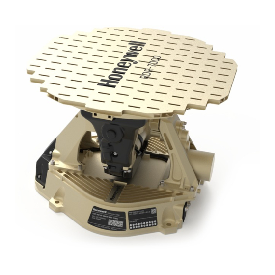
IntuVueRDR-7000 Weather Radar Pilot's Guide SECTION 4: EQUIPMENT DESCRIPTION UNIT DESCRIPTIONS ART-7000ANTENNA RECEIVER TRANSMITTER WITH FLAT PLATE ANTENNA The Antenna Receiver Transmitter (ART)is the main unit. It contains the electronics thattransmit, receive, and process the radar pulses used to detect turbulence, windshear, weather, and terrain targets. -
Page 36: Control Panelsand Displays
IntuVueRDR-7000 Weather Radar Pilot's Guide CONTROL PANELSand DISPLAYS The RDR-7000 can be used with many varieties of controllers, control panels, and displays. The controllers and displays used will vary with the aircraft and the installation. Although the location and appearance of the controls may vary, the functionality is the same, and is described below. - Page 37 IntuVueRDR-7000 Weather Radar Pilot's Guide D201911000094 Equipment Description Rev 0, Feb 2020...
-
Page 38: Operating Controls
IntuVueRDR-7000 Weather Radar Pilot's Guide OPERATING CONTROLS While the radar can be turned off completely by setting both sidesto OFF, this is not recommended. The radar operates by continuously scanning the whole sky in front of the aircraft, saving the results in 3-D memory. -
Page 39: Display Selection
IntuVueRDR-7000 Weather Radar Pilot's Guide provided, select ground override by pushing the HZD button four times within 3 seconds. If either side selects ground override, normal radar operation will commence. To return to Forced Standby, deselect ground override on the control panel, if such a control is available,orselect the standby radar mode. - Page 40 IntuVueRDR-7000 Weather Radar Pilot's Guide WX PATH – Automatic Weather Mode. Only On Path weather is shown (Off Path weather is suppressed). This mode provides display of weather out to 320 nm. If the Turbulence, REACT, and/or Hazard Display features are selected, those will also be shown. The Weather Ahead (TGT) function is active, if installed.
-
Page 41: Feature Control
IntuVueRDR-7000 Weather Radar Pilot's Guide FEATURE CONTROL The following controls may be available, depending on the installation and the controller in use. Consult the display system documentation for details of your system. It is strongly recommended that these features be selected for display if they are installed in your system. -
Page 42: Display Annunciations
IntuVueRDR-7000 Weather Radar Pilot's Guide DISPLAY ANNUNCIATIONS Actual annunciations are display dependent. The following images are provided as examples only. DISPLAY COLORS WEATHER RADAR DISPLAY COLORS Equipment Description D201911000094 Rev 0, Feb 2020... -
Page 44: Hail And Lightning Icons
IntuVueRDR-7000 Weather Radar Pilot's Guide HAIL AND LIGHTNING ICONS REACT INDICATIONS Equipment Description D201911000094 Rev 0, Feb 2020... -
Page 45: Predictive Windshear Annunciations
IntuVueRDR-7000 Weather Radar Pilot's Guide WEATHER AHEAD INDICATION Most displays will indicate Weather Ahead by using the TGT annunciation (usually ). Some may instead provide a text message (e.g., “WX AHEAD” or “TGT”) below the radar mode annunciation. Colors and locations may vary. If this feature is installed, it is always on, sothere is no separate “TGT armed”... -
Page 46: Fault Annunciations
IntuVueRDR-7000 Weather Radar Pilot's Guide FAULT ANNUNCIATIONS Fault annunciations alert the pilot that the radar system is not performing to established standards. Built-in test equipment (BITE) automatically and constantly tests the radar system. Failures will generally be indicated by the native mode annunciation on the display changing to amber.Some faults will result inalldisplayed radar data to go away entirely, or the radar may change to Standby mode. -
Page 47: Section 5: Principles Of Weather Radar Use
IntuVueRDR-7000 Weather Radar Pilot's Guide SECTION 5: PRINCIPLES OF WEATHER RADAR USE WEATHER RADAR PRINCIPLES Airborne weather avoidance radar, as its name implies, is for avoiding severe weather - not for penetrating it. Whether to fly into an area of radar echoes depends on echo intensity, spacing between the echoes, and the capabilities of both pilot and aircraft. -
Page 48: Storm Cell Characteristics
IntuVueRDR-7000 Weather Radar Pilot's Guide STORM CELL CHARACTERISTICS Airborne weather radar allows pilots to identify and avoid potential weather hazards. The radar performs signal processing to estimate the radar reflectivity of the weather ahead. Reflectivity correlates to precipitation rate, and is displayed as green (light), yellow (moderate), or red (heavy) precipitation. - Page 49 IntuVueRDR-7000 Weather Radar Pilot's Guide results from much more widespread and much less vigorous uplift. As a result, stratus precipitation is more layered in form with much lower gradients in radar reflectivity. However, the reflectivity of stratiform weather can be sufficient to cause yellow and red on the radar display.
-
Page 50: Planning A Path
IntuVueRDR-7000 Weather Radar Pilot's Guide PLANNING A PATH Remember to plan a deviation path early. Simply skirting the red or magenta portion of a cell is not enough. Wherever possible, plan an avoidance path for all weather echoes which display beyond 100 nm since this indicates they are quite dense. - Page 51 IntuVueRDR-7000 Weather Radar Pilot's Guide Hail and lightning icons identify which cells are likely producers of the associated hazard, but do not explicitly detect the present location of the hail or the lightning. Since lightning and hail can extend a significant distance from the core of the cell, the entire cell should be considered as containing the hazard.
- Page 52 IntuVueRDR-7000 Weather Radar Pilot's Guide If a squall line or system of cells must be penetrated, plan a path through the weather in a region of the least indicated hazard with the lowest reflectivity, generally staying upwind of the most severe hazards.
-
Page 53: Azimuth Resolution
IntuVueRDR-7000 Weather Radar Pilot's Guide strong returns from urban areas and mountainous regions, and others. Before making operational decisions based on small isolated indications on the weather display, the validity of these indications should be verified via PIREPS, ground-based weather sources and/or ATC communications. -
Page 54: Shadowed Areas
IntuVueRDR-7000 Weather Radar Pilot's Guide SHADOWED AREAS Extremely heavy rainfall or high terrain can reduce the ability of the radar to penetrate and present a full picture of the weather area. This is called radar attenuation. Use GMAP mode along with the weather modes to identify areas of shadowing. -
Page 55: Effects Of Interfering Rf Sources
IntuVueRDR-7000 Weather Radar Pilot's Guide EFFECTS OF INTERFERING RF SOURCES An interfering radio frequency (RF) source operating at a frequency close to the radar’s operating frequency can create unusual returns on the display. The interference may display as occasional isolated dots, or as radial spikes of any color (including magenta) on the display. - Page 56 IntuVueRDR-7000 Weather Radar Pilot's Guide In this figure, the interference is a bit more subtle, as it is mixed in with real weather. However, a close look reveals several radialspokes. The two most obvious ones have been circled. These figures show more examples of RF interference. Principles of Weather Radar Use D201911000094 Rev 0, Feb 2020...
-
Page 57: Radar Windshear Detection
IntuVueRDR-7000 Weather Radar Pilot's Guide RADAR WINDSHEAR DETECTION During both takeoff and landing, microbursts have been the cause of numerous aircraft accidents. WINDSHEAR/MICROBURST DESCRIPTION A microburst is a cool shaft of air, like a cylinder, between ½ and 1½ nm across that is moving downward. When it encounters the ground, the air mass mushrooms in a horizontal direction curling inward at the edges. -
Page 58: Windshear Avoidance Flying
IntuVueRDR-7000 Weather Radar Pilot's Guide WINDSHEAR AVOIDANCE FLYING The air shaft of a microburst creates problems for aircraft for two reasons. The first problem is due to the downward air movement. Since the aircraft is flying within the air mass, as the air mass plummets earthward, so does the aircraft. -
Page 59: Section 6: Rdr-7000Technical Operation
IntuVueRDR-7000 Weather Radar Pilot's Guide SECTION 6: RDR-7000TECHNICAL OPERATION 3D VOLUMETRIC MEMORY SCANNING/PROCESSING The RDR-7000 collects a complete 3D volumetric scan of all the weather and terrain ahead of the aircraft. The RDR-7000 contains internal worldwide topographical information, enabling it to extract ground clutter without the significant losses associated with signal- based ground clutter suppression techniques. -
Page 60: Ground Clutter Extraction
IntuVueRDR-7000 Weather Radar Pilot's Guide GROUND CLUTTER EXTRACTION The radar processor contains an internal terrain database with elevation data. The radar compares the collected reflectivity data with the terrain database. Reflectivity data that correlates to terrain data is considered ground- clutter, and is suppressed from the weather images. -
Page 61: On Path Weather Vs. Off Path Weather
IntuVueRDR-7000 Weather Radar Pilot's Guide ON PATH WEATHER VS. OFF PATH WEATHER The WXALLorWX PATH modesare used for the strategic detection of weather. This fully automatic weather detection is enabled by the 3D volumetric memory. In these modes, OnPath weather, or weather near the altitude of the intended flight path, is displayed as distinct from Off Pathweather, which is further removed in altitude from the flight path. -
Page 63: Weather Analysis Mode: Manual Altitude
IntuVueRDR-7000 Weather Radar Pilot's Guide WEATHER ANALYSIS MODE: MANUAL ALTITUDE Manual Altitude mode is an analysis mode providing a constant elevation slice throughout the entire 180-degree plan view. It is called constant elevation because the elevation slice extracted from the memory is corrected for the earth’s curvature. With traditional tilt angle settings the earth curves away from the beam farfrom the aircraft making it difficult to exactly measure the height of a cell. - Page 64 IntuVueRDR-7000 Weather Radar Pilot's Guide The example below demonstrates the WX MAN mode. In the top center picture, the system is in the WX ALL mode at an aircraft altitude of 20,000 feet MSL. In the second center picture, WX MANmode has been selected.This is an elevation slice at the current aircraft altitude (20,000 feet MSL).
-
Page 65: Appendix
IntuVueRDR-7000 Weather Radar Pilot's Guide APPENDIX SAFETY INFORMATION CAUTION MAINTAIN PRESCRIBED SAFE DISTANCE WHEN STANDING IN FRONT OF A RADIATING ANTENNA.* *Reference FAA Advisory Circular #20-68B D201911000094 Safety Information Rev 0, Feb 2020... -
Page 66: Maximum Permissible Exposure Level (Mpel)
IntuVueRDR-7000 Weather Radar Pilot's Guide MAXIMUM PERMISSIBLE EXPOSURE LEVEL (MPEL) FAA advisory circular AC 20-68B defines the method for determining the MPEL boundary. All personnel should remain beyond the distance indicated in the illustration below. Manufacturers are required to calculate two distances; the MPEL boundary is determined by the greater of these two distances. - Page 67 IntuVueRDR-7000 Weather Radar Pilot's Guide D201911000094 Safety Information Rev 0, Feb 2020...
- Page 68 Honeywell International Inc. 15001 N.E. 36th Street • P.O. Box 97001 Redmond, Washington USA 98073-9701 CAGE 97896 D201911000094Rev 0, Feb 2020 © 2020 Honeywell International Inc.