Sign In
Upload
Manuals
Brands
GE Manuals
Controller
N60
GE N60 Manuals
Manuals and User Guides for GE N60. We have
9
GE N60 manuals available for free PDF download: Instruction Manual, Communications Manual
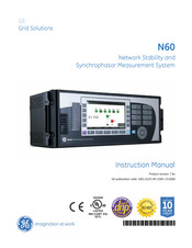
GE N60 Instruction Manual (644 pages)
Network Stability and Synchrophasor Measurement System UR Series
Brand:
GE
| Category:
Controller
| Size: 11 MB
Table of Contents
Table of Contents
3
1 Getting Started
11
Important Procedures
11
Cautions and Warnings
11
Inspection Procedure
12
Ur Overview
13
Introduction to the Ur
13
Hardware Architecture
13
Software Architecture
14
Enervista Ur Setup Software
15
System Requirements
15
Installation
15
Configuring the N60 for Software Access
16
Using the Quick Connect Feature
19
Connecting to the N60 Relay
24
Setting up Cybersentry and Changing Default Password
25
Ur Hardware
27
Mounting and Wiring
27
Communications
27
Faceplate Display
27
Using the Relay
28
Faceplate Keypad
28
Menu Navigation
28
Menu Hierarchy
28
Relay Activation
29
Relay Passwords
29
Flexlogic Customization
29
Commissioning
30
2 Product Description
31
Introduction
31
Overview
31
Security
33
Iec 870-5-103 Protocol
37
Order Codes
38
Overview
38
Order Codes with Enhanced Ct/Vt Modules
38
Order Codes with Process Bus Modules
40
Replacement Modules
41
Specifications
43
Protection Elements
43
User-Programmable Elements
44
Monitoring
46
Metering
46
Inputs
47
Power Supply
48
Outputs
48
Communication Protocols
50
Inter-Relay Communications
50
Environmental
51
Type Tests
52
Production Tests
53
Approvals
53
Maintenance
53
3 Hardware
55
Description
55
Panel Cutout
55
Rear Terminal Layout
57
Wiring
58
Typical Wiring
58
Dielectric Strength
59
Control Power
59
Ct and Vt Modules
60
Process Bus Modules
62
Contact Inputs and Outputs
62
Transducer Inputs and Outputs
70
Rs232 Faceplate Port
71
Cpu Communication Ports
72
Irig-B
74
Direct Input and Output Communications
75
Description
75
Fiber: Led and Eled Transmitters
76
Fiber-Laser Transmitters
77
Interface
77
Rs422 Interface
81
Two-Channel Two-Clock Rs422 Interface
83
Rs422 and Fiber Interface
83
Ieee C37.94 Interface
84
4 Human Interfaces
89
Enervista Ur Setup Software Interface
89
Introduction
89
Creating a Site List
89
Enervista Ur Setup Overview
89
Enervista Ur Setup Main Window
91
Extended Enervista Ur Setup Features
92
Settings Templates
92
Securing and Locking Flexlogic Equations
96
Settings File Traceability
98
Faceplate Interface
101
Faceplate
101
Led Indicators
102
Custom Labeling of Leds
105
Display
110
Keypad
110
Breaker Control
111
Menus
112
Changing Settings
114
Advertisement
GE N60 Instruction Manual (666 pages)
Network Stability and Synchrophasor
Brand:
GE
| Category:
Measuring Instruments
| Size: 24.2 MB
Table of Contents
Table of Contents
3
1 Introduction
11
Safety Symbols and Definitions
11
General Cautions and Warnings
11
For Further Assistance
12
2 Product Description
15
Description
16
Security
17
Order Codes
21
Order Codes with Enhanced CT/VT Modules
22
Order Codes with Process Bus Modules
24
Replacement Modules
26
Signal Processing
27
UR Signal Processing
27
Specifications
29
Protection Elements
30
User-Programmable Elements
33
Monitoring
35
Metering
36
Inputs
37
Power Supply
39
Outputs
39
Communication Protocols
41
Inter-Relay Communications
42
Cybersentry Security
44
Graphical Front Panel
44
Environmental
44
Type Tests
45
Production Tests
45
Approvals
46
Maintenance
46
3 Installation
47
Unpack and Inspect
47
Panel Cutouts
48
Rear Terminal Layout
51
Wiring
53
Typical Wiring
53
Dielectric Strength
54
Control Power
54
CT/VT Modules
55
Process Bus Modules
57
Contact Inputs and Outputs
58
Transducer Inputs and Outputs
69
RS232 Port
71
CPU Communication Ports
72
Irig-B
74
Direct Input and Output Communications
75
Description
75
Fiber: LED and ELED Transmitters
78
Fiber Laser Transmitters
78
Interface
79
RS422 Interface
83
Two-Channel Two-Clock RS422 Interface
85
RS422 and Fiber Interface
86
IEEE C37.94 Interface
86
Activate Relay
89
Install Software
90
Enervista Communication Overview
90
System Requirements
91
Install Software
92
Add Device to Software
93
Set IP Address in UR
93
Configure Serial Connection
98
Configure Ethernet Connection
99
Configure Modem Connection
101
Automatic Discovery of UR Devices
101
Connect to the N60
102
Connect to the N60 in Enervista
102
Use Quick Connect Via the Front Panel RS232 Port
103
Use Quick Connect Via a Rear Ethernet Port
104
Set up Cybersentry and Change Default Password
105
Import Settings
105
Connect to D400 Gateway
106
Oscillography Files
106
Event Records
106
Log Files
106
Setting Files
107
4 Interfaces
109
Enervista Software Interface
109
Introduction
109
Settings Files
109
Event Viewing
110
File Support
111
Enervista Main Window
111
Protection Summary Window
112
Settings Templates
113
Secure and Lock Flexlogic Equations
117
Settings File Traceability
120
Front Panel Interface
122
Front Panel
122
Front Panel Display
124
Front Panel Navigation Keys
145
LED Indicators
147
Front Panel Labelling
151
Menu Navigation
158
Change Settings
160
View Actual Values
165
Breaker Control
166
Change Passwords
167
Invalid Password Entry
169
Logic Diagrams
169
Flexlogic Design Using Engineer
170
Design Logic
172
Send File to and from Device
182
Monitor Logic
183
View Front Panel and Print Labels
184
Generate Connectivity Report
185
Preferences
185
Toolbars
189
GE N60 Instruction Manual (602 pages)
Network Stability and Synchrophasor Measurement System UR Series
Brand:
GE
| Category:
Measuring Instruments
| Size: 10.86 MB
Table of Contents
Table of Contents
3
1 Getting Started
15
Important Procedures
15
Cautions and Warnings
15
Inspection Procedure
15
Ur Overview
17
Introduction to the Ur
17
Hardware Architecture
18
Software Architecture
19
Important Concepts
19
Enervista Ur Setup Software
20
Pc Requirements
20
Installation
20
Configuring the N60 for Software Access
21
Using the Quick Connect Feature
24
Connecting to the N60 Relay
30
Ur Hardware
31
Mounting and Wiring
31
Communications
31
Faceplate Display
31
Using the Relay
32
Faceplate Keypad
32
Menu Navigation
32
Menu Hierarchy
32
Relay Activation
32
Relay Passwords
33
Flexlogic™ Customization
33
Commissioning
34
2 Product Description
35
Introduction
35
Overview
35
Ordering
38
Replacement Modules
39
Specifications
43
Monitoring
43
Metering
44
Inputs
45
Power Supply
46
Outputs
46
Communications
48
Inter-Relay Communications
49
Environmental
49
Type Tests
50
Production Tests
51
Approvals
51
Maintenance
51
Description
51
Panel Cutout
53
Module Withdrawal and Insertion
55
Rear Terminal Layout
56
Wiring
58
Typical Wiring
58
GE Multilin N60 Network Stability and Synchrophasor Measurement System
59
Dielectric Strength
59
Control Power
59
Ct and Vt Modules
60
Process Bus Modules
62
Contact Inputs and Outputs
62
Transducer Inputs and Outputs
70
Rs232 Faceplate Port
72
Cpu Communication Ports
72
Irig-B
76
Direct Input and Output Communications
78
Description
78
Fiber: Led and Eled Transmitters
80
Fiber-Laser Transmitters
80
Interface
82
Rs422 Interface
85
Two-Channel Two-Clock Rs422 Interface
87
Rs422 and Fiber Interface
87
Ieee C37.94 Interface
88
Managed Ethernet Switch Modules
91
Overview
91
Managed Ethernet Switch Module Hardware
91
Managed Switch Led Indicators
92
Initial Setup of the Ethernet Switch Module
92
Configuring the Managed Ethernet Switch Module
96
Uploading N60 Switch Module Firmware
99
Ethernet Switch Self-Test Errors
101
4 Human Interfaces
103
Enervista Ur Setup Software Interface
103
Introduction
103
Creating a Site List
103
Enervista Ur Setup Overview
103
Enervista Ur Setup Main Window
105
Extended Enervista Ur Setup Features
107
Settings Templates
107
Securing and Locking Flexlogic™ Equations
111
Settings File Traceability
113
Faceplate Interface
116
Faceplate
116
Led Indicators
117
Custom Labeling of Leds
120
Display
124
Keypad
124
Breaker Control
124
Menus
125
Changing Settings
126
Advertisement
GE N60 Instruction Manual (614 pages)
UR Series Network Stability and Synchrophasor Measurement System
Brand:
GE
| Category:
Measuring Instruments
| Size: 10.8 MB
Table of Contents
Table of Contents
3
1 Getting Started
11
Important Procedures
11
Cautions and Warnings
11
Inspection Procedure
12
Ur Overview
13
Introduction to the Ur
13
Hardware Architecture
13
Software Architecture
15
Important Concepts
15
Enervista Ur Setup Software
16
Pc Requirements
16
Installation
16
Configuring the N60 for Software Access
17
Using the Quick Connect Feature
20
Connecting to the N60 Relay
25
Setting up Cybersentry and Changing Default Password
26
Ur Hardware
28
Mounting and Wiring
28
Communications
28
Faceplate Display
28
Using the Relay
29
Faceplate Keypad
29
Menu Navigation
29
Menu Hierarchy
29
Relay Activation
29
Relay Passwords
30
Flexlogic Customization
30
Commissioning
31
2 Product Description
33
Introduction
33
Overview
33
Security
35
Ordering
40
Replacement Modules
42
Specifications
44
Protection Elements
44
User-Programmable Elements
45
Monitoring
47
Metering
47
Inputs
48
Power Supply
49
Outputs
49
Communication Protocols
51
Inter-Relay Communications
51
Environmental
52
Type Tests
53
Production Tests
54
Approvals
54
Maintenance
54
Description
54
Panel Cutout
55
Rear Terminal Layout
57
Wiring
58
Typical Wiring
58
Dielectric Strength
59
Control Power
59
Ct and Vt Modules
60
Process Bus Modules
62
Contact Inputs and Outputs
62
Transducer Inputs and Outputs
70
Rs232 Faceplate Port
71
Cpu Communication Ports
72
Irig-B
74
Direct Input and Output Communications
75
Description
75
Fiber: Led and Eled Transmitters
77
Fiber-Laser Transmitters
77
Interface
78
Rs422 Interface
81
Two-Channel Two-Clock Rs422 Interface
83
Rs422 and Fiber Interface
83
Ieee C37.94 Interface
84
4 Human Interfaces
89
Enervista Ur Setup Software Interface
89
Introduction
89
Creating a Site List
89
Enervista Ur Setup Overview
89
Enervista Ur Setup Main Window
91
Extended Enervista Ur Setup Features
92
Settings Templates
92
Securing and Locking Flexlogic Equations
96
Settings File Traceability
98
Faceplate Interface
101
Faceplate
101
Led Indicators
102
Custom Labeling of Leds
105
Display
109
Keypad
109
Breaker Control
109
Menus
110
Changing Settings
113
GE N60 Instruction Manual (596 pages)
Network Stability and Synchrophasor Measurement System
Brand:
GE
| Category:
Measuring Instruments
| Size: 21.39 MB
Table of Contents
Table of Contents
3
1 Introduction
9
Safety Symbols and Definitions
9
General Cautions and Warnings
9
For Further Assistance
10
2 Product Description
13
Description
13
Overview
13
Security
15
Order Codes
19
Order Codes with Enhanced CT/VT Modules
20
Order Codes with Process Bus Modules
22
Replacement Modules
24
Signal Processing
25
UR Signal Processing
25
Specifications
27
Protection Elements
28
User-Programmable Elements
31
Monitoring
33
Metering
34
Inputs
35
Power Supply
37
Outputs
37
Communication Protocols
39
Inter-Relay Communications
40
Cybersentry Security
42
Environmental
42
Type Tests
43
Production Tests
43
Approvals
44
Maintenance
44
3 Installation
45
Unpack and Inspect
45
Panel Cutouts
46
Rear Terminal Layout
48
Wiring
50
Typical Wiring
50
Dielectric Strength
51
Control Power
51
CT/VT Modules
52
Process Bus Modules
54
Contact Inputs and Outputs
55
Transducer Inputs and Outputs
66
RS232 Faceplate Port
67
CPU Communication Ports
68
Irig-B
70
Direct Input and Output Communications
71
Description
71
Fiber: LED and ELED Transmitters
74
Fiber Laser Transmitters
74
Interface
75
RS422 Interface
79
Two-Channel Two-Clock RS422 Interface
81
RS422 and Fiber Interface
82
IEEE C37.94 Interface
82
Activate Relay
85
Install Software
86
Enervista Communication Overview
86
System Requirements
87
Install Software
88
Add Device to Software
89
Set IP Address in UR
89
Configure Serial Connection
95
Configure Ethernet Connection
96
Configure Modem Connection
98
Automatic Discovery of UR Devices
98
Connect to the N60
99
Connect to the N60 in Enervista
99
Use Quick Connect Via the Front Panel RS232 Port
100
Use Quick Connect Via a Rear Ethernet Port
101
Set up Cybersentry and Change Default Password
101
Import Settings
102
4 Interfaces
105
Enervista Software Interface
105
Introduction
105
Settings Files
105
Event Viewing
106
File Support
107
Enervista Main Window
107
Protection Summary Window
108
Settings Templates
109
Secure and Lock Flexlogic Equations
113
Settings File Traceability
116
Front Panel Interface
119
Front Panel Display
119
Front Panel Keypad
120
Menu Navigation
120
Menu Hierarchy
120
Changing Settings
121
Faceplate
123
LED Indicators
124
Custom LED Labeling
127
Breaker Control
132
Change Passwords
133
Invalid Password Entry
134
Logic Diagrams
135
Flexlogic Design and Monitoring Using Engineer
136
Design Logic
138
Send File to and from Device
148
Monitor Logic
149
View Front Panel and Print Labels
150
Generate Connectivity Report
151
Preferences
151
Toolbars
155
GE N60 Instruction Manual (544 pages)
Network Stability and Synchrophasor Measurement System UR Series
Brand:
GE
| Category:
Measuring Instruments
| Size: 10.28 MB
Table of Contents
Table of Contents
5
Cautions and Warnings
13
Introduction to the Ur
14
Hardware Architecture
15
Software Architecture
16
Pc Requirements
17
Configuring the N60 for Software Access
18
Using the Quick Connect Feature
21
Connecting to the N60 Relay
27
Mounting and Wiring
28
Faceplate Keypad
29
Relay Passwords
30
Commissioning
31
C.5 Iec 61850 Implementation Via Enervista Ur Setup
33
Overview
33
Ordering
35
Replacement Modules
36
Protection Elements
38
User-Programmable Elements
39
Monitoring
40
Metering
41
Power Supply
42
Outputs
43
Communications
44
Inter-Relay Communications
45
Environmental
46
Production Tests
47
Panel Cutout
49
Module Withdrawal and Insertion
51
Rear Terminal Layout
52
Typical Wiring
54
Dielectric Strength
55
Ct and Vt Modules
56
Process Bus Modules
58
Transducer Inputs and Outputs
66
Rs232 Faceplate Port
67
Irig-B
71
Description
72
Fiber: Led and Eled Transmitters
74
G.703 Interface
75
Rs422 Interface
78
Two-Channel Two-Clock Rs422 Interface
80
Ieee C37.94 Interface
81
3.3 Direct Input and Output Communications
72
C.4 Generic Substation Event Services: Gsse and Goose
84
Overview
84
Managed Switch Led Indicators
85
Uploading N60 Switch Module Firmware
88
Ethernet Switch Self-Test Errors
90
3.4 Managed Ethernet Switch Modules
85
C.1 Overview
91
Introduction
91
Enervista Ur Setup Main Window
93
Settings Templates
94
Securing and Locking Flexlogic™ Equations
98
Settings File Traceability
100
4.2 Extended Enervista Ur Setup Features
103
Faceplate
103
Led Indicators
104
Custom Labeling of Leds
107
Display
112
Menus
113
Changing Settings
115
5.1 Overview
119
Settings Main Menu
119
Introduction to Elements
122
Introduction to Ac Sources
123
Security
126
5.2 Product Setup
130
Display Properties
130
Clear Relay Records
132
GE N60 Instruction Manual (460 pages)
Network Stability and Synchrophasor Measurement System
Brand:
GE
| Category:
Measuring Instruments
| Size: 9.39 MB
Table of Contents
Table of Contents
3
1 Introduction
9
Safety Symbols and Definitions
9
General Cautions and Warnings
9
For Further Assistance
10
2 Product Description
11
Overview
11
Security
13
Order Codes
17
Order Codes with Enhanced CT/VT Modules
18
Order Codes with Process Bus Modules
20
Replacement Modules
21
Specifications
22
Protection Elements
23
User-Programmable Elements
25
Monitoring
27
Metering
28
Inputs
29
Power Supply
30
Outputs
31
Communication Protocols
33
Inter-Relay Communications
34
Environmental
35
Type Tests
36
Production Tests
36
Approvals
37
Maintenance
37
3 Installation
39
Unpack and Inspect
39
Panel Cutouts
40
Rear Terminal Layout
42
Wiring
43
Typical Wiring
43
Dielectric Strength
44
Control Power
44
CT/VT Modules
45
Process Bus Modules
47
Contact Inputs and Outputs
47
Transducer Inputs and Outputs
54
RS232 Faceplate Port
56
CPU Communication Ports
56
Irig-B
58
Direct Input and Output Communications
59
Description
59
Fiber: LED and ELED Transmitters
61
Fiber Laser Transmitters
61
Interface
62
RS422 Interface
66
Two-Channel Two-Clock RS422 Interface
68
RS422 and Fiber Interface
68
IEEE C37.94 Interface
69
Activate Relay
72
Install Software
73
Enervista Communication Overview
73
System Requirements
74
Install Software
74
Configure the N60 for Software Access
75
Configure Serial Communication
76
Configure Ethernet Connection
77
Automatic Discovery of UR Devices
78
Connect to the N60
78
Connect to the N60 in Enervista
78
Use Quick Connect Via the Front Panel RS232 Port
79
Use Quick Connect Via a Rear Ethernet Port
80
Set up Cybersentry and Change Default Password
85
4 Interfaces
87
Enervista Software Interface
87
Introduction
87
Settings Files
87
Event Viewing
88
File Support
88
Enervista Main Window
88
Settings Templates
89
Secure and Lock Flexlogic Equations
94
Settings File Traceability
96
Front Panel Interface
98
Front Panel Display
98
Front Panel Keypad
98
Menu Navigation
99
Menu Hierarchy
99
Changing Settings
100
Faceplate
101
LED Indicators
102
Custom LED Labeling
105
Breaker Control
111
Change Passwords
112
Invalid Password Entry
113
Logic Diagrams
114
GE N60 Communications Manual (532 pages)
Universal Relay Family
Brand:
GE
| Category:
Relays
| Size: 3.79 MB
Table of Contents
Table of Contents
3
1 Introduction
7
Products
7
Features Per Product
7
Communication Ports
20
Safety Symbols and Definitions
20
For Further Assistance
20
Modbus
21
2 Modbus Communication
21
Modbus RTU Protocol
21
Introduction
21
Configuration
21
Physical Layer
21
Data Link Layer
22
Modbus RTU CRC-16 Algorithm
23
Modbus Function Codes
24
Supported Function Codes
24
Read Actual Values or Settings (Function Code 03/04H)
24
Execute Operation (Function Code 05H)
25
Store Single Setting (Function Code 06H)
25
Store Multiple Settings (Function Code 10H)
26
Exception Responses
26
File Transfers
27
Obtaining Relay Files Using Modbus
27
Memory Map
32
Modbus Memory Map
32
6 Iec 60870-5-104
80
Communication
81
Data Formats
204
3 Iec 61850 Communication
239
Overview
239
Introduction
239
Abstract Communication Service Interface (ASCI)
241
Datasets
244
Txgoose
245
Rxgoose
247
Reports
248
Commands
250
Substation Configuration Language (SCL)
250
Configuring the UR Using SCL
256
Merge SCL File
261
Configurable Logical Devices
262
Protocol Implementation Conformance Statement (PICS)
262
Basic Conformance Statement
262
ACSI Conformance Statement
263
ACSI Basic Conformance Statement
263
ACSI Models Conformance Statement
263
ACSI Services Conformance Statement
265
Model Implementation Conformance Statement (MICS)
267
Master (Root) Logical Device
268
Protection (Prot) Logical Device
275
Control (Ctrl) Logical Device
354
System Logical Device
389
Meter Logical Device
410
General (Gen) Logical Device
431
GE Namespace
447
Enumerations
462
SCL Implementation Conformance Statement (SICS)
463
PIXIT Conformance Statement
465
TICS Conformance Statement
470
SCL Logging
472
Overview of Process
472
SCL File Storage on UR
473
Generation of CID Files
473
Schema Version Used by Ur/Enervista
473
CID File Processing Steps
473
SCL Log File Format and Examples
473
Troubleshooting Log File Errors
475
G2 Implementation Model for GOOSE Configuration Via SCL
475
Introduction
475
Configuration Process
476
Configuration Process with IED Setup Tool
478
IED Capability Description (ICD) File
478
Instantiated IED Capability Description (IID) File
482
Configured IED Description (CID) File
482
Sample SCL Files
484
Annex - Optional Intermediate GOOSE Reception Objects
489
E3-2.0 Implementation Model for GOOSE Configuration Via SCL
492
Introduction
492
Workflow
492
ICD Files
493
CID Files
494
IID Files
495
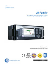
GE N60 Communications Manual (526 pages)
UR Family
Brand:
GE
| Category:
Controller
| Size: 3.78 MB
Table of Contents
Table of Contents
3
1 Introduction
7
Products
7
Features Per Product
7
Communication Ports
20
Safety Symbols and Definitions
20
For Further Assistance
20
Modbus
21
2 Modbus Communication
21
Modbus RTU Protocol
21
Introduction
21
Configuration
21
Physical Layer
21
Data Link Layer
22
Modbus RTU CRC-16 Algorithm
23
Modbus Function Codes
24
Supported Function Codes
24
Read Actual Values or Settings (Function Code 03/04H)
24
Execute Operation (Function Code 05H)
25
Store Single Setting (Function Code 06H)
25
Store Multiple Settings (Function Code 10H)
26
Exception Responses
26
File Transfers
27
Obtaining Relay Files Using Modbus
27
Memory Map
32
Modbus Memory Map
32
6 Iec 60870-5-104
80
Communication
81
Data Formats
203
3 Iec 61850 Communication
239
Overview
239
Introduction
239
Abstract Communication Service Interface (ASCI)
241
Datasets
244
Txgoose
245
Rxgoose
247
Reports
248
Commands
250
Substation Configuration Language (SCL)
250
Configuring the UR Using SCL
256
Merge SCL File
261
Configurable Logical Devices
262
Protocol Implementation Conformance Statement (PICS)
262
Basic Conformance Statement
262
ACSI Conformance Statement
263
ACSI Basic Conformance Statement
263
ACSI Models Conformance Statement
263
ACSI Services Conformance Statement
265
Model Implementation Conformance Statement (MICS)
267
Master (Root) Logical Device
268
Protection (Prot) Logical Device
275
Control (Ctrl) Logical Device
351
System Logical Device
385
Meter Logical Device
406
General (Gen) Logical Device
426
GE Namespace
442
Enumerations
457
SCL Implementation Conformance Statement (SICS)
458
PIXIT Conformance Statement
460
TICS Conformance Statement
465
SCL Logging
467
Overview of Process
467
SCL File Storage on UR
468
Generation of CID Files
468
Schema Version Used by Ur/Enervista
468
CID File Processing Steps
468
SCL Log File Format and Examples
468
Troubleshooting Log File Errors
470
G2 Implementation Model for GOOSE Configuration Via SCL
470
Introduction
470
Configuration Process
471
Configuration Process with IED Setup Tool
473
IED Capability Description (ICD) File
473
Instantiated IED Capability Description (IID) File
477
Configured IED Description (CID) File
477
Sample SCL Files
479
Annex - Optional Intermediate GOOSE Reception Objects
484
E3-2.0 Implementation Model for GOOSE Configuration Via SCL
487
Introduction
487
Workflow
487
ICD Files
488
CID Files
489
IID Files
490
Advertisement
Related Products
GE N60 UR Series
GE TELSTRASATURN NZ 29393
GE NX-1448E - Security NetworX 48-Zone Fixed
GE NetworX NX-1500E
GE NetworX NX-148E-CF-W
GE Next Step Control
GE NX-4-EUR
GE Novaspec Plus
GE NetworX NX-1710E
GE NBVllA Series
GE Categories
Refrigerator
Ranges
Microwave Oven
Air Conditioner
Dishwasher
More GE Manuals
Login
Sign In
OR
Sign in with Facebook
Sign in with Google
Upload manual
Upload from disk
Upload from URL