Toro 04384 Service Manual
Hide thumbs
Also See for 04384:
- Operator's manual (48 pages) ,
- Operator's manual (48 pages) ,
- Operator's manual (52 pages)
Table of Contents
Advertisement
Quick Links
Preface
The purpose of this publication is to provide the service
technician with information for troubleshooting, testing
and repair of major systems and components on the
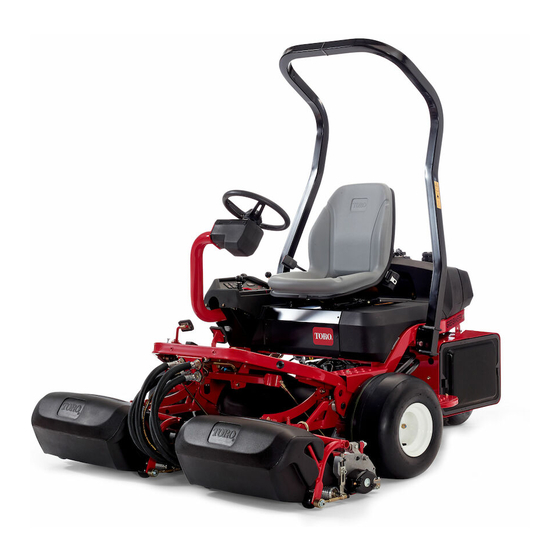
Greensmaster 3250--D (Model 04384).
REFER TO THE TRACTION UNIT AND CUTTING
UNIT OPERATOR'S MANUALS FOR OPERATING,
MAINTENANCE AND ADJUSTMENT INSTRUC-
TIONS. Space is provided in Chapter 2 of this book to
insert the Operator's Manuals and Parts Catalogs for
your machine. Additional copies of the Operator's
Manuals and Parts Catalog are available on the internet
at www.Toro.com.
The Toro Company reserves the right to change product
specifications or this publication without notice.
Greensmaster
This safety symbol means DANGER, WARNING
or CAUTION, PERSONAL SAFETY INSTRUC-
TION. When you see this symbol, carefully read
the instructions that follow. Failure to obey the
instructions may result in personal injury.
NOTE: A NOTE will give general information about the
correct operation, maintenance, service, testing or re-
pair of the machine.
IMPORTANT: The IMPORTANT notice will give im-
portant instructions which must be followed to pre-
vent damage to systems or components on the
machine.
E The Toro Company - - 2012
Part No. 12186SL
Service Manual
(Model 04384)
R
3250- -D
Advertisement
Chapters
Table of Contents
Troubleshooting

Related Manuals for Toro 04384


Summary of Contents for Toro 04384
-
Page 1: Service Manual
The Toro Company reserves the right to change product IMPORTANT: The IMPORTANT notice will give im- specifications or this publication without notice. portant instructions which must be followed to pre- vent damage to systems or components on the machine. - Page 2 This page is intentionally blank. Greensmaster 3250--D...
-
Page 3: Table Of Contents
Table Of Contents Chapter 1 - - Safety Chapter 5 - - Electrical System Safety Instructions ......1 -- 2 General Information . - Page 4 This page is intentionally blank. Greensmaster 3250--D...
-
Page 5: Safety Instructions 1
Chapter 1 Safety Table of Contents SAFETY INSTRUCTIONS ..... . Before Operating ......While Operating . -
Page 6: Safety Instructions
Safety Instructions The Greensmaster 3250--D was tested and certified by The safety alert symbol means Toro for compliance with national and international stan- CAUTION, WARNING or DANGER — dards as specified in the Operator’s Manual. Although “personal safety instruction”. Read... -
Page 7: While Operating
While Operating 1. Do not run the engine in a confined area without ade- 7. The Greensmaster 3250--D may exceed noise levels quate ventilation. Exhaust fumes are hazardous and of 85 dB(A) at the operator position. Ear protectors are could be deadly. recommended, for prolonged exposure, to reduce the potential of permanent hearing damage. -
Page 8: Safety And Instruction Decals
The Toro Company. 5. Before disconnecting or performing any work on the 13.When changing attachments, tires or performing hydraulic system, all pressure in system must be re- other service, use correct hoists and jacks. -
Page 9: Product Records
Chapter 2 Product Records and Maintenance Table of Contents PRODUCT RECORDS ......MAINTENANCE ....... EQUIVALENTS AND CONVERSIONS . -
Page 10: Equivalents And Conversions
Equivalents and Conversions 0.09375 Product Records and Maintenance Page 2 - - 2 Greensmaster 3250--D... -
Page 11: Torque Specifications
For critical applications, as determined reduced by 25% for lubricated fasteners to achieve by Toro, either the recommended torque or a torque that the similar stress as a dry fastener. Torque values may is unique to the application is clearly identified and spe- also have to be reduced when the fastener is threaded cified in this Service Manual. - Page 12 Standard Torque for Dry, Zinc Plated and Steel Fasteners (Inch Series) Grade 1, 5 & SAE Grade 1 Bolts, Screws, Studs & SAE Grade 5 Bolts, Screws, Studs & SAE Grade 8 Bolts, Screws, Studs & Thread Size 8 with Thin Sems with Regular Height Nuts Sems with Regular Height Nuts Sems with Regular Height Nuts...
-
Page 13: Standard Torque For Dry, Zinc Plated And Steel Fasteners (Metric Fasteners)
Standard Torque for Dry, Zinc Plated and Steel Fasteners (Metric Fasteners) Class 8.8 Bolts, Screws and Studs with Class 10.9 Bolts, Screws and Studs with Thread Size Thread Size Regular Height Nuts Regular Height Nuts Regular Height Nuts Regular Height Nuts (Class 8 or Stronger Nuts) (Class 10 or Stronger Nuts) M5 X 0.8... - Page 14 Other Torque Specifications SAE Grade 8 Steel Set Screws Wheel Bolts and Lug Nuts Recommended Torque Thread Size Recommended Torque** Thread Size Thread Size Square Head Hex Socket 7/16 -- 20 UNF 65 + 10 ft--lb 88 + 14 N--m Grade 5 1/4 -- 20 UNC 140 + 20 in--lb...
-
Page 15: Specifications
Chapter 3 Diesel Engine Table of Contents SPECIFICATIONS ......GENERAL INFORMATION ..... Operator’s Manual . - Page 16 This page is intentionally blank. Diesel Engine Page 3 - - 2 Greensmaster 3250--D...
-
Page 17: Specifications
Specifications Item Description Make / Designation Kubota water--cooled, Diesel, Model D902--E3B Number of Cylinders Bore x Stroke 2.83” x 2.9” (72mm x 73.6mm) Total Displacement 54.8 in (898 cc) Compression Ratio 24.0:1 Firing Order 1 (closest to gear case end) -- 2 -- 3 (closest to flywheel end) Direction of Rotation Counterclockwise (viewed from flywheel) Fuel... -
Page 18: Sm--E3B Series
Service and repair parts for the Kubota engine that pow- ers your Greensmaster 3250--D are supplied through your local Toro distributor. If no parts list is available, be sure to provide your distributor with the Toro model and serial number. -
Page 19: Adjust Throttle Control
Adjustments Adjust Throttle Control Proper throttle operation is dependent upon proper ad- justment of throttle control. Make sure throttle control is operating properly. NOTE: The throttle cable swivel should be positioned in the lowest hole in the speed control lever. 1. -
Page 20: Air Cleaner
Service and Repairs Air Cleaner RIGHT FRONT Figure 4 1. Air cleaner assembly 5. Air cleaner hose 9. Flange nut (4 used) 2. Air inlet hood 6. Flange head screw 10. Air cleaner bracket 3. Mounting bracket 7. R- -clamp 11. - Page 21 Air Cleaner Removal (Fig. 4) 1. Park machine on a level surface, lower the cutting units, stop the engine, engage parking brake and re- move the key from the ignition switch. 2. Remove air cleaner components as needed using Figure 4 as a guide. 3.
-
Page 22: Exhaust System
Exhaust System RIGHT FRONT Figure 6 1. Muffler 7. Lower muffler mount 13. Spring (4 used) 2. Flat washer (10 used) 8. Flange nut 14. Exhaust gasket 3. Lock nut (4 used) 9. Engine mount 15. Exhaust plate 4. Upper muffler mount 10. - Page 23 Exhaust System Removal (Fig. 6) 1. Park machine on a level surface, lower the cutting units, stop the engine, engage parking brake and re- move the key from the ignition switch. CAUTION The muffler and exhaust pipe may be hot. To avoid possible burns, allow the engine and ex- haust system to cool before working on the muf- fler.
-
Page 24: Radiator
Radiator RIGHT FRONT Figure 8 1. Hose clamp (4 used) 9. Flange nut (5 used) 17. Upper radiator hose 2. Lower radiator hose 10. Screen 18. Flange head screw (5 used) 3. Hose connector (2 used) 11. Swell latch (2 used) 19. - Page 25 4. If machine is equipped with optional hydraulic oil B. Secure upper rear corner of radiator support to cooler (Fig. 9), drain hydraulic reservoir and remove oil frame with flange head screw (item 18) and flange cooler (see Oil Cooler in the Service and Repairs section nut (item 9).
-
Page 26: Fuel Tank
Fuel Tank RIGHT FRONT Antiseize Lubricant 30 to 60 in- -lb (3.4 to 6.8 N- -m) Figure 10 1. Fuel cap 12. Cap 23. Tank vent hose 2. Fuel tank 13. Mounting plate 24. Fuel pump 3. Flange bushing (3 used) 14. - Page 27 Fuel Tank Removal (Fig. 10) 8. If necessary, remove shut--off valve and fitting as- sembly from fuel tank (Fig. 11). The nut and fitting have 1. Park machine on a level surface, lower cutting units, left hand threads. stop the engine, engage parking brake and remove the key from the ignition switch.
-
Page 28: Engine
Engine RIGHT FRONT Figure 12 1. Engine assembly 8. Flange head screw (4 used) 15. Flat washer (3 used) 2. Ground harness 9. Flange head screw (6 used) 16. Flange nut (3 used) 3. Flange head screw 10. Engine mount (3 used) 17. -
Page 29: Engine Removal
Engine Removal (Fig. 12) 1. Park machine on a level surface, lower cutting units, stop engine, engage parking brake and remove key from the ignition switch. CAUTION The engine, radiator, exhaust system and hy- draulic system may be hot. To avoid possible in- jury, allow machine to cool before working on the engine. -
Page 30: Engine Installation
Loctite #242 CAUTION 27 to 33 ft- -lb (37 to 44 N- -m) Support the hydraulic pump assembly when re- moving its supporting fasteners to prevent it from falling and causing damage or personal in- jury. 9. Support hydraulic pump assembly to prevent it from moving during engine removal. - Page 31 8. Connect all electrical harness connectors to engine 13.Remove plugs placed during engine removal from using labels placed during engine removal. fuel hoses. Connect fuel supply hose to the injector pump fitting and fuel return hose to the #3 injector fitting. 9.
-
Page 32: Engine Bell Housing
Engine Bell Housing Loctite #242 17 to 21 ft- -lb (23 to 28 N- -m) FRONT RIGHT Loctite #242 17 to 21 ft- -lb (23 to 28 N- -m) Figure 17 1. Engine 3. Bell housing 5. Flange head screw (4 used) 2. -
Page 33: Specifications 4
Chapter 4 Hydraulic System Table of Contents SPECIFICATIONS ......SERVICE AND REPAIRS ..... GENERAL INFORMATION . - Page 34 This page is intentionally blank. Hydraulic System Page 4 - - 2 Greensmaster 3250--D...
-
Page 35: Specifications
Specifications Item Description Piston (Traction) Pump Variable displacement piston pump Maximum Pump Displacement (per revolution) 1.24 in (20.3 cc) Charge Pressure 100 to 150 PSI (7 to 10 bar) Gear Pump 2 section, positive displacement gear pump Front Section (cutting reels) Displacement (per revolution) 0.58 in (9.5 cc) Rear Section (steering/lift) Displacement (per revolution) -
Page 36: General Information
NOTE: A red dye additive for the hydraulic system fluid is available in 2/3 oz bottles. One bottle is sufficient for 4 to 6 gallons of hydraulic fluid. Order Part No. 44--2500 from your Authorized Toro Distributor. Hydraulic System Page 4 - - 4... -
Page 37: Towing Traction Unit
Towing Traction Unit In case of emergency, the Greensmaster 3250--D can be towed for a short distance. However, Toro does not recommend this as a standard practice. IMPORTANT: Do not tow the machine faster than 2 to 3 mph because drive system may be damaged. If machine must be moved a considerable distance, transport it on a truck or trailer. -
Page 38: Hydraulic Hoses
Tube Installation in this section). If the hose has an el- bow at one end, tighten the swivel nut on that end before tightening the nut on the straight end of the hose. For additional hydraulic hose information, refer to Toro Service Training Book, Hydraulic Hose Servicing (Part Number 94813SL). -
Page 39: Hydraulic Hose And Tube Installation
Hydraulic Hose and Tube Installation (O- -Ring Face Seal Fitting) 1. Make sure threads and sealing surfaces of the hose/ C. Use a second wrench to tighten the nut to the cor- tube and the fitting are free of burrs, nicks, scratches or rect Flats From Wrench Resistance (F.F.W.R.). - Page 40 Hydraulic Fitting Installation (SAE Straight Thread O- -Ring Fitting into Component Port) Non- -Adjustable Fitting (Fig. 6) 5. If a torque wrench is not available, or if space at the port prevents use of a torque wrench, an alternate meth- 1.
- Page 41 Adjustable Fitting (Fig. 8) 1. Make sure all threads and sealing surfaces of fitting and component port are free of burrs, nicks, scratches or any foreign material. 2. As a preventative measure against leakage, it is rec- ommended that the O--ring be replaced any time the connection is opened.
-
Page 42: Hydraulic Schematic
Hydraulic Schematic Hydraulic System Page 4 - - 10 Greensmaster 3250--D... - Page 43 This page is intentionally blank. Greensmaster 3250--D Page 4 - - 11 Hydraulic System...
-
Page 44: Hydraulic Flow Diagrams
Hydraulic Flow Diagrams Hydraulic System Page 4 - - 12 Greensmaster 3250--D... -
Page 45: Traction Circuits
Traction Circuits Forward Reverse The piston (traction) pump is driven directly by the en- The traction circuit operates essentially the same in re- gine. The traction circuit of the hydraulic system acts es- verse as it does in the forward direction. However, the sentially as a closed loop. - Page 46 Hydraulic System Page 4 - - 14 Greensmaster 3250--D...
-
Page 47: Raise And Lower Cutting Units
Raise and Lower Cutting Units The tandem gear pump is directly coupled to the piston Lower Cutting Units (traction) pump. The rear gear pump section supplies Circuit operation for lowering the lift cylinders is similar hydraulic flow for the steering circuit (priority flow), for to raising them. - Page 48 Hydraulic System Page 4 - - 16 Greensmaster 3250--D...
-
Page 49: Mow And Backlap
Mow and Backlap The tandem gear pump is directly coupled to the piston Oil flow from manifold port (P1) flows through the reel (traction) pump. The front gear pump section supplies speed control valve (FC). Flow across the speed control oil flow to the hydraulic manifold block and to the cutting valve is pressure compensated by the logic cartridge reel motors. -
Page 50: Right And Left Turn
RIGHT TURN LEFT TURN Steering Cylinder Steering Cylinder STEERING STEERING VALVE VALVE 1160 PSI 1160 PSI TO CONTROL TO CONTROL MANIFOLD MANIFOLD PORT ST PORT ST TO CONTROL TO CONTROL MANIFOLD MANIFOLD PORT P2 PORT P2 FROM GEAR FROM GEAR PUMP PUMP Greensmaster 3250--D... - Page 51 Right and Left Turn The tandem gear pump is directly coupled to the piston Left Turn (traction) pump. The rear gear pump section supplies When a left turn is made with the engine running, the hydraulic flow for the steering circuit (priority flow), for turning of the steering wheel positions the spool valve in raising and lowering the cutting units and for the traction the steering valve so that flow goes through the top of...
-
Page 52: Special Tools
Special Tools Order these special tools from your Toro Distributor. Hydraulic Pressure Test Kit Use to take various pressure readings for diagnostic tests. Quick disconnect fittings provided attach directly to mating fittings on machine test ports without tools. A high pressure hose is provided for remote readings. - Page 53 Toro Part Number: TOR6011 NOTE: This kit does not include hydraulic hoses (see Hydraulic Hose Kit TOR6007 above). NOTE: Replacement filter element is Toro part number TOR6012. Filter element cannister tightening torque is 25 ft- -lb (34 N- -m). Hydraulic Hose Kit...
-
Page 54: Measuring Container
Hydraulic Test Fitting Kit This kit includes a variety of O--ring face seal fittings to TORO TEST FITTING KIT (NO. TOR4079) enable you to connect test gauges into the system. The kit includes: tee’s, unions, reducers, plugs, caps and male test fittings. -
Page 55: Troubleshooting
Troubleshooting The charts that follow contain information to assist in Refer to the Testing section of this Chapter for precau- troubleshooting. There may possibly be more than one tions and specific test procedures. cause for a machine malfunction. General Hydraulic System Problems Problem Possible Cause Hydraulic oil leaks from system. -
Page 56: Traction Circuit Problems
Traction Circuit Problems Problem Possible Cause Neutral is difficult to find or unit oper- External traction control linkage is misadjusted, disconnected, bind- ates in one direction only. ing or damaged. Piston (traction) pump is worn or damaged (see Piston (Traction) Pump Flow Test). -
Page 57: Mow Circuit Problems
Mow Circuit Problems Problem Possible Cause Gear pump is noisy (cavitation). Oil level in reservoir is low (other hydraulic circuits affected as well). Hydraulic pump suction line is restricted. Hydraulic pump suction line has an air leak. Reels will not turn. Solenoid valve S1R1 is stuck open or damaged. -
Page 58: Lift/Lower Circuit Problems
Lift/Lower Circuit Problems Problem Possible Cause Cutting units will not lift or lift slowly. Engine speed is too low. Oil level in reservoir is low (other hydraulic circuits affected as well). Lift cylinder linkage is binding or broken. Lift cylinder bushings bind. Charge circuit pressure is low (see Charge Relief Valve Pressure Test). -
Page 59: Steering Circuit Problems
Steering Circuit Problems Problem Possible Cause Steering wheel is hard to turn. Steering valve has insufficient oil flow (charge and lift circuits af- fected as well). Emergency steering ball in steering valve is missing or damaged. Regular adjustments to steering Leaf springs in steering valve are worn or broken. -
Page 60: Testing
Testing The most effective method for isolating problems in the 1. Clean machine thoroughly before disconnecting or hydraulic system is by using hydraulic test equipment disassembling any hydraulic components. Always keep such as pressure gauges and flow meters in the circuits in mind the need for cleanliness when working on hy- during various operational checks (see the Special draulic equipment. - Page 61 3. For traction related problems (e.g. machine will not 5. For issues with the cutting system, consider perform- go up an incline), consider performing the following hy- ing the following hydraulic tests: draulic tests: Mow Circuit Relief Valve (S1R1) Pressure Test Charge Pressure Relief Valve Pressure Test Reel Motor Case Drain Flow Test Wheel Motor Efficiency Test...
-
Page 62: Charge Relief Valve Pressure Test
Charge Relief Valve Pressure Test (Using Pressure Gauge) PRESSURE GAUGE Hydraulic System Page 4 - - 30 Greensmaster 3250--D... - Page 63 Procedure for Charge Relief Valve Pressure Test 10.A dynamic charge pressure test can be performed as follows: The traction charge circuit is designed to replace loss of hydraulic fluid from the closed loop traction circuit. The A. Position machine so that a load can be placed on charge relief valve pressure test will identify if charge the traction system.
-
Page 64: Wheel Motor Efficiency Test
Wheel Motor Efficiency Test (Using Tester with Flowmeter and Pressure Gauge) TO STEERING VALVE ILLUSTRATION SHOWS TEST FOR LEFT FRONT MOTOR FROM CONTROL TO CONTROL MANIFOLD PORT PT MANIFOLD PORT P1 TESTER TRACTION PUMP PORT RIGHT LEFT BYPASS 10.3 MOTOR 10.3 MOTOR VALVE... - Page 65 4. Attach a heavy chain to the rear of the machine frame 16.Test second front wheel motor. Reconnect hydraulic and an immovable object to prevent the machine from lines to untested front wheel motor. Disconnect and cap moving during testing. hydraulic lines to tested front wheel motor.
- Page 66 Piston (Traction) Pump Flow Test (Using Tester with Flowmeter and Pressure Gauge) TO STEERING VALVE FROM CONTROL TO CONTROL MANIFOLD PORT PT MANIFOLD PORT P1 TRACTION PUMP TESTER PORT BYPASS RIGHT LEFT VALVE 10.3 10.3 MOTOR MOTOR 3000 PSI GEAR ENGINE RPM 1.24 3000 PSI...
-
Page 67: Adjustments 4
4. Raise and support machine so front wheels are off 13.If flow was less than 12 GPM (45 LPM) or a pressure the ground to allow flow through the traction circuit. If of 1000 PSI (69 bar) cannot be obtained, consider the machine is equipped with 3 wheel drive, raise and sup- following: port machine so rear wheel is off the ground as well. - Page 68 Gear Pump (Rear Section) Flow Test (Using Tester with Flowmeter and Pressure Gauge) TESTER Hydraulic System Page 4 - - 36 Greensmaster 3250--D...
-
Page 69: Gear Pump (Rear Section) Flow Test
Procedure for Gear Pump (Rear Section) Flow Test 9. Flow gauge reading for a rear gear pump section in good condition should be approximately 3.6 GPM (13.6 1. Make sure hydraulic oil is at normal operating tem- LPM). Record test results. perature by operating the machine for approximately ten (10) minutes. -
Page 70: Implement Relief Valve Pressure Test
Implement Relief Valve Pressure Test (Using Pressure Gauge) TESTER Hydraulic System Page 4 - - 38 Greensmaster 3250--D... -
Page 71: Service And Repairs 4
Procedure for Implement Relief Valve Pressure Test 10.Implement relief valve pressure should be 1050 to 1250 PSI (73 to 86 bar) higher than the charge relief 1. Make sure hydraulic oil is at normal operating tem- valve (R4) pressure (e.g. if the charge relief valve pres- perature by operating the machine for approximately ten sure is 100 PSI (7 bar), the implement relief valve pres- (10) minutes. -
Page 72: Lower Cutting Units Relief Valve (R2) Pressure Test (Using Tester With Flowmeter And
Lower Cutting Units Relief Valve (R2) Pressure Test (Using Tester with Flowmeter and Pressure Gauge) TESTER Hydraulic System Page 4 - - 40 Greensmaster 3250--D... - Page 73 Procedure for Lower Cutting Units Relief Valve (R2) NOTE: The lower cutting units relief valve is in series Pressure Test with the charge relief valve. Charge relief pressure will affect the lower cutting units relief pressure. 1. Make sure hydraulic oil is at normal operating tem- perature by operating the machine for approximately ten 9.
-
Page 74: Gear Pump (Front Section) Flow Test (Using Tester With Flowmeter And Pressure
Gear Pump (Front Section) Flow Test (Using Tester with Flowmeter and Pressure Gauge) Hydraulic System Page 4 - - 42 Greensmaster 3250--D... - Page 75 Procedure for Gear Pump (Front Section) Flow Test 7. Watch pressure gauge carefully while slowly closing the flow control valve on the tester until 2000 PSI (138 1. Make sure hydraulic oil is at normal operating tem- bar) is obtained. perature by operating the machine for approximately ten (10) minutes.
-
Page 76: Mow Circuit Relief Valve (S1R1) Pressure Test (Using Tester With Flowmeter And
Mow Circuit Relief Valve (S1R1) Pressure Test (Using Tester with Flowmeter and Pressure Gauge) TESTER Hydraulic System Page 4 - - 44 Greensmaster 3250--D... - Page 77 Procedure for Mow Circuit Relief Valve (S1R1) Pres- 10.After recording relief pressure, disengage cutting sure Test units. Open control valve on tester and shut off engine. 1. Make sure hydraulic oil is at normal operating tem- A. If relief valve pressure is correct, go to step 11. perature by operating the machine for approximately ten B.
-
Page 78: Reel Motor Case Drain Flow Test
Reel Motor Case Drain Flow Test (Using Tester with Flowmeter and Pressure Gauge) CENTER MOTOR RETURN RIGHT MOTOR CASE DRAIN RIGHT MOTOR RETURN LEFT MOTOR CASE DRAIN CENTER MOTOR CASE DRAIN LEFT MOTOR RETURN CENTER MOTOR LEFT MOTOR RIGHT MOTOR TESTER ILLUSTRATION SHOWS TEST FRONT RIGHT... - Page 79 1. Make sure hydraulic oil is at normal operating tem- duated in ounces or milliliters (e.g. Toro #TOR4077) and perature by operating the machine for approximately ten collect hydraulic fluid for fifteen (15) seconds. After fif- (10) minutes.
-
Page 80: Steering Valve Test
Steering Valve Test Steering Cylinder (CYLINDER ROD FULLY RETRACTED) PLUG STEERING VALVE TURNED FOR RIGHT TURN 1160 PSI TO CONTROL MANIFOLD PORT ST TO CONTROL MANIFOLD PORT P2 FROM GEAR PUMP Hydraulic System Page 4 - - 48 Greensmaster 3250--D... - Page 81 Procedure for Steering Valve Test 1. Make sure the hydraulic tank is full. 2. Make sure hydraulic oil is at normal operating tem- perature by operating the machine for approximately ten (10) minutes. 3. Drive machine slowly in a figure eight on a flat level surface.
-
Page 82: Adjustments
Adjustments Adjust Manifold Relief Valve (R2) The hydraulic manifold includes an adjustable relief valve in the lift circuit (Fig. 29). If adjustment to this valve FRONT is necessary, follow the following procedure. NOTE: Do not remove relief valve from the hydraulic manifold for adjustment. - Page 83 This page is intentionally blank. Greensmaster 3250--D Page 4 - - 51 Hydraulic System...
-
Page 84: Service And Repairs
Service and Repairs General Precautions for Removing and Installing Hydraulic System Components Before Repair or Replacement of Components After Repair or Replacement of Components 1. Before removing any parts from the hydraulic sys- 1. Check oil level in the hydraulic reservoir and add cor- tem, park machine on a level surface, engage parking rect oil if necessary. -
Page 85: Flush Hydraulic System
Flush Hydraulic System IMPORTANT: Flush the hydraulic system any time 7. Disconnect electrical connector to the fuel stop sole- there is a severe component failure or the system is noid to prevent engine from starting on diesel engine. contaminated (oil appears milky or black or con- 8. -
Page 86: Filtering Closed--Loop Traction Circuit
To effectively remove contamination from through the traction circuit and high flow filter. Keep trac- closed--loop traction circuit, use of the Toro high flow hy- tion circuit engaged for five (5) minutes while gradually draulic filter and hydraulic hose kits are recommended increasing both forward pressure on traction pedal and (see Special Tools in this chapter). -
Page 87: Hydraulic System Start--Up
Hydraulic System Start- -up NOTE: When initially starting the hydraulic system with CAUTION new or rebuilt components such as motors, pumps or lift cylinders, it is important that this start--up procedure be used. This procedure reduces the chance of damaging the system or its components from not purging the sys- Be careful when operating the cutting unit reels. -
Page 88: Gear Pump
Gear Pump RIGHT FRONT Figure 33 1. Pump inlet hose 7. Hose clamp (2 used) 13. Socket head screw (2 used) 2. Gear pump 8. O- -ring 14. Flat washer (2 used) 3. Hydraulic fitting 9. O- -ring 15. Hydraulic hose 4. - Page 89 Removal (Fig. 33) 4. Secure gear pump to the piston pump with two (2) socket head screws and flat washers. 5. Inspect threads and sealing surfaces of hydraulic fit- CAUTION tings and hydraulic hose connectors. Replace any dam- aged or worn fittings or hoses. Before continuing further, read and become fa- 6.
-
Page 90: Gear Pump Service
Gear Pump Service 33 ft- -lb (45 N- -m) Figure 35 1. O- -ring 9. Dowel pin 16. Drive gear 2. Front cover 10. O- -ring 17. Idler gear 3. Back- -up seal 11. Housing 18. Thrust plate 4. Pressure seal 12. - Page 91 6. Support the pump assembly and gently tap the Gear Pump Assembly (Fig. 35) pump housing with a soft face hammer to loosen the 1. Apply clean hydraulic oil to all parts before assem- pump sections. Be careful to not drop parts or disen- bling.
-
Page 92: Piston (Traction) Pump Neutral Assembly
Piston (Traction) Pump Neutral Assembly Antiseize Lubricant RIGHT FRONT Figure 37 1. Lock nut 15. Bearing spacer 29. Flat washer (2 used) 2. Nylon washer (2 used) 16. Ball bearing 30. Lock nut (3 used) 3. Cap screw 17. Extension spring 31. - Page 93 Disassembly (Fig. 37) 1. Park machine on a level surface, engage parking brake, lower cutting units and stop engine. Remove key from the ignition switch. 2. If necessary, remove muffler to allow disassembly of traction neutral assembly (Fig. 39). Refer to Exhaust System in the Service and Repairs section of Chapter 3 -- Diesel Engine for additional information on muffler re- moval.
-
Page 94: Piston (Traction) Pump
Piston (Traction) Pump Loctite #242 27 to 33 ft- -lb (37 to 44 N- -m) RIGHT FRONT Figure 40 1. Hose clamp (2 used) 11. Cap screw 20. O- -ring 2. O- -ring 12. Cap screw (2 used) 21. O- -ring 3. - Page 95 Piston Pump Removal (Fig. 40) 1. Park machine on a level surface, engage parking brake, lower cutting units and stop engine. Remove key from the ignition switch. CAUTION Before continuing further, read and become fa- miliar with General Precautions for Removing and Installing Hydraulic System Components.
- Page 96 IMPORTANT: If fittings are going to be removed 6. Lubricate and place new O--rings onto all removed from piston pump, note position of fittings for as- hydraulic fittings. Install fittings into pump openings sembly purposes. making sure that fitting orientation is as noted during re- moval.
- Page 97 This page is intentionally blank. Greensmaster 3250--D Page 4 - - 65 Hydraulic System...
-
Page 98: Piston (Traction) Pump Service
Piston (Traction) Pump Service REAR OF TRACTION UNIT Figure 44 1. Key 15. Dowel pin 29. Housing 2. Drive shaft 16. Back plate 30. Retaining ring 3. Bearing 17. O- -ring 31. Bearing race 4. Cap screw (3 used per plate) 18. - Page 99 For repair of the piston pump, see Eaton, Medium Duty Piston Pump, Repair Information, Model 70160 Variable Displacement Piston Pump at the end of this chapter. NOTE: The charge relief valve is attached to the piston pump back plate (shown in Fig. 45). The back plate must be removed to service the relief valve.
-
Page 100: Piston (Traction) Pump Crush Ring Replacement
Piston Pump Crush Ring Replacement 29 ft- -lb (39 N- -m) Figure 46 1. Crush ring 5. Swash plate (control shaft) 8. O- -ring 2. Shims 6. Bearing cone 9. Washer (3 used) 3. Cover plate 7. Bearing cup 10. Cap screws (3 used) 4. - Page 101 This page is intentionally blank. Greensmaster 3250--D Page 4 - - 69 Hydraulic System...
-
Page 102: Front Wheel Motors
Front Wheel Motors 250 to 400 ft- -lb (339 to 540 N- -m) RH 15 LH 16 15 RH 16 LH 70 to 90 ft- -lb (95 to122 N- -m) Antiseize Lubricant RIGHT FRONT Figure 47 1. Lug nut (4 used per wheel) 11. - Page 103 Front Wheel Motor Removal (Fig. 47) Front Wheel Motor Installation (Fig. 47) 1. Park the machine on a level surface, lower the cut- 1. Position hydraulic wheel motor and brake bracket ting units and stop the engine. Remove key from the (item 14) to the frame.
-
Page 104: Rear Wheel Motor (If Equipped With 3Wd)
Rear Wheel Motor (If Equipped with 3WD) 70 to 90 ft- -lb (95 to122 N- -m) 100 ft- -lb (135 N- -m) 80 to 100 in- -lb (9 to 11 N- -m) RIGHT FRONT 40 ft- -lb (55 N- -m) Figure 48 1. - Page 105 This page is intentionally blank. Greensmaster 3250--D Page 4 - - 73 Hydraulic System...
-
Page 106: Wheel Motor Service
Wheel Motor Service Figure 49 1. Dirt seal 9. Thrust bearing 17. Woodruff key 2. Bearing 10. Bearing 18. Wear plate 3. Housing 11. Coupling shaft 19. Rotor 4. Back- -up washer 12. Thrust bearing 20. Vane 5. Seal ring 13. - Page 107 This page is intentionally blank. Greensmaster 3250--D Page 4 - - 75 Hydraulic System...
-
Page 108: Cutting Reel Motors
Cutting Reel Motors FRONT REEL MOTORS RIGHT FRONT Figure 50 1. Cap screw 11. Washer 21. Hydraulic tube 2. Flat washer 12. Spacer 22. Hydraulic tube 3. Tube clamp 13. Reel motor 23. Hydraulic tube 4. Lock nut 14. Hose assembly 24. - Page 109 5. If hydraulic fittings are to be removed from reel mo- 4. Rotate the motor counterclockwise until the motor tor, mark fitting orientation to allow correct assembly. flanges are encircling the cap screws. Tighten two (2) Remove hydraulic fittings and O--rings from motor. Dis- cap screws to secure reel motor to cutting unit.
-
Page 110: Reel Motor Service
Reel Motor Service 215 to 280 in- -lb (24 to 32 N- -m) Figure 52 1. Rear cover 5. Pressure seal 9. Idler gear 2. Drive gear 6. Back- -up ring 10. Cap screw (4 used) 3. Seal 7. O- -ring 11. - Page 111 IMPORTANT: Mark the relative positions of the gear teeth and the bearing blocks so they can be re- assembled in the same position. Do not touch the gear surfaces as residue on hands may be corrosive to gear finish. 7. Place the motor on its side and push on the rear bear- ing block to remove the bearing block and gear set (Fig.
- Page 112 Assembly 8. Install dowel pins in body. NOTE: When assembling the motor, check the identifi- IMPORTANT: Do not dislodge O- -rings, pressure cation marks made during disassembly to make sure seals or back- -up rings during final assembly. the parts are properly aligned during assembly. 9.
- Page 113 This page is intentionally blank. Greensmaster 3250--D Page 4 - - 81 Hydraulic System...
-
Page 114: Oil Cooler (If Equipped)
Oil Cooler (If Equipped) OIL FLOW Figure 57 1. Oil cooler 7. Hydraulic tube 12. Radiator support 2. Lower formed hose 8. Hydraulic straight fitting 13. Hydraulic filter 3. Upper formed hose 9. 90 hydraulic fitting 14. Hydraulic tank 4. Grommet (2 used) 10. - Page 115 4. Loosen hose clamps securing the formed hoses to 9. Plug ends of the oil cooler. Clean exterior of the cool- the oil cooler. 5. Carefully pull oil cooler from the cooler brackets in 10.The oil cooler should be free of corrosion and exces- the radiator support.
-
Page 116: Lift Cylinders
Lift Cylinders RIGHT FRONT FRONT LIFT CYLINDER CENTER LIFT CYLINDER Figure 58 1. Hydraulic hose 8. Washer head screw 15. Center lift arm 2. Hydraulic hose 9. Pivot pin 16. Center lift cylinder 3. O- -ring 10. Spacer 17. Hydraulic hose 4. - Page 117 Lift Cylinder Installation (Fig. 58) 4. Position clevis of the lift cylinder to the lift arm. Insert clevis pin (item 5) through the cylinder clevis and lift arm. 1. If fittings were removed from lift cylinder, lubricate Secure pin with cotter pin (item 4). and place new O--rings onto fittings.
-
Page 118: Lift Cylinder Service
Lift Cylinder Service CENTER HYDRAULIC CYLINDER 40 ft- -lb (54 N- -m) Figure 59 1. Barrel 5. T seal 9. O- -ring 2. Shaft 6. O- -ring 10. Back- -up ring 3. Nut 7. Rod seal 11. Dust seal 4. Piston 8. - Page 119 Disassembly IMPORTANT: Do not clamp vise jaws against the shaft surface. Protect shaft surface before mount- 1. Remove oil from lift cylinder into a drain pan by slowly ing in a vise. pumping the cylinder shaft. Plug both ports and clean the outside of the cylinder.
-
Page 120: Hydraulic Manifold
Hydraulic Manifold Figure 61 1. Hydraulic manifold assembly 12. Cap screw (2 used) 23. O- -ring 2. Hydraulic adapter (2 used) 13. Hydraulic hose 24. Hydraulic tube 3. Hydraulic tee fitting 14. Hydraulic hose 25. O- -ring 4. Hydraulic test fitting 15. - Page 121 Removal (Fig. 61) Installation (Fig. 61) 1. Park the machine on a level surface, engage the 1. If fittings were removed from manifold, lubricate and parking brake, lower the cutting units and stop the en- place new O--rings onto fittings. Install fittings into mani- gine.
-
Page 122: Hydraulic Manifold Service
Hydraulic Manifold Service 20 ft- -lb 60 in- -lb (27 N- -m) (6.7 N- -m) 25 ft- -lb (34 N- -m) 20 ft- -lb (27 N- -m) 25 ft- -lb (34 N- -m) 60 in- -lb (6.7 N- -m) 20 ft- -lb (27 N- -m) 40 ft- -lb (54 N- -m) - Page 123 NOTE: The ports on the hydraulic manifold are marked 5. Cleaning cartridge valves: for easy identification of components. Example: FC1 is A. For non--solenoid operated valves: the flow control valve and P1 is the gear pump connec- Submerge valve in clean mineral spirits to flush out tion port (See Hydraulic Schematic to identify the func- contamination.
- Page 124 Rotary Cartridge Valve IMPORTANT: Use care when installing the rotary cartridge valve. Slight bending or distortion of 1. Remove rotary handle from valve (Fig. 63): the stem tube can cause binding and malfunc- tion. Make sure that deep well socket fully en- A.
- Page 125 Mow/Backlap Spool (Fig. 64) 1. Make sure manifold is clean before removing the mow/backlap spool. Loctite 603 2. Remove mow/backlap spool from manifold: A. Remove backlap switch from manifold before re- moving mow/backlap spool. Remove dowel pin and ball from manifold port after switch is removed. Re- move and discard O--ring from switch.
-
Page 126: Steering Valve
Steering Valve 20 to 26 ft- -lb (28 to 35 N- -m) Antiseize Lubricant Figure 65 1. Knob 12. Bushing (2 used) 23. Steering valve 2. Lockup handle 13. Socket head screw (6 used) 24. Thrust washer 3. Lockup spacer 14. - Page 127 Removal (Fig. 65) 3. While routing hydraulic hose to machine, position steering valve to steering mount. Secure steering valve 1. Park the machine on a level surface, engage the to steering mount with four (4) flange head screws (item parking brake, lower the cutting units and stop the en- gine.
-
Page 128: Steering Valve Service
Steering Valve Service 20 to 24 ft- -lb (27 to 33 N- -m) Figure 67 1. Plug 11. Thrust washer 21. Inner gearwheel 2. Plug 12. Bearing 22. End cover 3. Spring 13. Cross pin 23. O- -ring (5 used) 4. - Page 129 This page is intentionally blank. Greensmaster 3250--D Page 4 - - 97 Hydraulic System...
-
Page 130: Steering Cylinder
Steering Cylinder CYLINDER ASSEMBLY 65 to 85 ft- -lb (88 to 115 N- -m) 65 to 85 ft- -lb (88 to 115 N- -m) RIGHT FRONT Figure 68 1. Slotted hex nut 13. Flange head screw (3 used) 25. Hydraulic hose 2. - Page 131 Removal (Fig. 68) 9. If the rear ball joint needs to be removed, accomplish the following: 1. Park the machine on a level surface, engage the parking brake, lower the cutting units and stop the en- A. Block front wheels. Jack up rear wheel off the gine.
-
Page 132: Steering Cylinder Service
Steering Cylinder Service Figure 69 1. Rod 6. O- -ring 11. Wear ring 2. Wiper 7. Wear ring 12. Retaining ring 3. Seal 8. Barrel 13. Piston 4. Head (non- -ball joint end) 9. Back- -up ring 14. Head (ball joint end) 5. - Page 133 Disassembly (Fig. 69) Assembly (Fig. 69) 1. Pump oil out of cylinder into a drain pan by slowly NOTE: The seal kit includes several O--rings, backup moving rod in and out of cylinder bore. Plug ports and rings and wear rings that cannot be accessed on the clean outside of cylinder.
-
Page 134: Hydraulic Reservoir
Hydraulic Reservoir Antiseize Lubricant 30 to 60 in- -lb (3.4 to 6.8 N- -m) Figure 70 12. Flat washer (4 used) 23. Hose clamp 1. Strainer 2. 90 hydraulic fitting 13. Grommet (4 used) 24. Serrated plug 3. Fuel tank clamp 14. - Page 135 5. Remove cap screw and flat washer securing the con- PUMP INLET HOSE sole shroud to the hydraulic tank. Remove both cap screws and flat washers securing the console shroud to the lower panel (Fig. 73). 6. Remove three (3) washer head screws that secure the mounting plate (item 29) to the frame.
- Page 136 Turf Guardian Leak Detector System (If Equipped) 17 to 21 ft- -lb (23 to 28 N- -m) 17 to 21 ft- -lb (23 to 28 N- -m) 100 to 125 in- -lb 30 to 60 in- -lb (11.3 to 14.1 N- -m) (3.4 to 6.8 N- -m) Figure 74 1.
- Page 137 Removal (Fig. 74) 1. Park the machine on a level surface, engage the parking brake, lower the cutting units and stop the en- gine. Remove key from the ignition switch. CAUTION Before continuing further, read and become fa- miliar with General Precautions for Removing and Installing Hydraulic System Components.
- Page 138 IMPORTANT: Do not over tighten cap screw. 2. Secure sight gauge (item 34) and new O--ring (item Threads in tank may become damaged. 28) to the leak detection tank. Torque gauge from 100 to 125 in- -lb (11.3 to 14.1 N- -m). 6.
-
Page 139: Troubleshooting 5
Chapter 5 Electrical System Table of Contents GENERAL INFORMATION ..... Solenoid Valve Coils ......Operator’s Manual . - Page 140 This page is intentionally blank. Greensmaster 3250--D Electrical System Page 5 - - 2...
-
Page 141: General Information
General Information Operator’s Manual The Operator’s Manual provides information regarding the operation, general maintenance and maintenance intervals for your Greensmaster 3250--D. Refer to that publication for additional information when servicing the machine. Electrical Drawings The electrical schematic and other electrical drawings for the Greensmaster 3250--D are located in Chapter 9 -- Foldout Drawings. -
Page 142: Special Tools
The multimeter can test electrical components and cir- cuits for current, resistance or voltage. Obtain this tool locally. NOTE: Toro recommends the use of a DIGITAL Volt-- Ohm--Amp multimeter when testing electrical circuits. The high impedance (internal resistance) of a digital me- ter in the voltage mode will make sure that excess cur- rent is not allowed through the meter. - Page 143 Connectors should be thoroughly packed with gel for effective re- sults. Toro Part Number: 107- -0342 Figure 4 Battery Hydrometer Use the Battery Hydrometer when measuring specific gravity of battery electrolyte.
-
Page 144: Troubleshooting
Troubleshooting For effective troubleshooting and repairs, there must be CAUTION a good understanding of the electrical circuits and com- ponents used on this machine (see electrical schematic and other electrical drawings in Chapter 9 -- Foldout Remove all jewelry, especially rings and Drawings). - Page 145 Starting Problems (continued) Problem Possible Causes Engine cranks (but should not) with Neutral sensor is out of adjustment. the functional control lever in the Neutral sensor or circuit wiring is faulty. MOW or TRANSPORT position. Interlock relay or circuit wiring is faulty. Engine cranks, but does not start.
-
Page 146: General Run And Transport Problems
General Run and Transport Problems Problem Possible Causes Engine kills when the Functional Operator is sitting too far forward on the seat (seat switch not Control Lever is in the MOW or depressed). TRANSPORT position with the Seat switch or circuit wiring is faulty. operator in the seat. -
Page 147: Cutting Unit Operating Problems
Cutting Unit Operating Problems Problem Possible Causes Cutting units run (but should not) when Joystick relay or circuit wiring is faulty. raised. Solenoid valve S1R1 or circuit wiring is faulty. Mow relay or circuit wiring is faulty. Mow sensor or circuit wiring is faulty. Cutting units do not run when lowered Fuse F1 (10 ampere) or fuse block is faulty. -
Page 148: Electrical System Quick Checks
Electrical System Quick Checks Battery Test Use a multimeter to measure the voltage between the Voltage Measured Battery Charge Level battery terminals. 12.68 V (or higher) Fully charged (100%) Set the multimeter to the DC volts setting. The battery 12.45 V 75% charged should be at a temperature of 60 to 100... -
Page 149: Component Testing
Component Testing For accurate resistance and/or continuity checks, elec- trically disconnect the component being tested from the CAUTION circuit (e.g. unplug the ignition switch connector before doing a continuity check). When testing electrical components for continu- NOTE: For engine component testing information, re- ity with a multimeter (ohms setting), make sure fer to the Kubota Workshop Manual. -
Page 150: Fuse Block
Fuse Block Fuses can be removed to check continuity. The test me- ter should read less than 1 ohm. Fuses supply power to the following (Fig. 8): 1. Fuse F1 (top) (10 ampere) supplies power to the run and mow relays. 2. -
Page 151: Warning Light Cluster
Warning Light Cluster Glow Plug Indicator Light The glow plug indicator light should come on when the ignition switch is placed in the RUN position prior to plac- ing the ignition switch in START. The light should stay lit for approximately six (6) seconds while the ignition switch is left in the RUN position. -
Page 152: Seat Switch
Seat Switch The seat switch is normally open and closes when the operator is on the seat. If the neutral switch or traction interlock switch is open when the operator raises out of the seat, the engine will stop. The switch and its electri- cal connector are located directly under the seat. -
Page 153: Lower Reels Time Delay
Lower Reels Time Delay The lower reels time delay is a solid state timer. Upon the application of power, the load is energized and the time delay is started. After six (6) seconds the load is de--en- ergized. The time delay is attached to a bracket under the control console (Fig. -
Page 154: Diode Circuit Boards
DIODE CIRCUIT Apply dielectric grease (Toro part number 107--0342) to BOARD circuit board contacts whenever the circuit board is installed into the wire harness. NOTE: The Greensmaster 3250--D does not use diodes D1--B or D2--B. -
Page 155: Solenoid Valve Coils
Solenoid Valve Coils The Greensmaster hydraulic control manifold uses sev- eral hydraulic solenoid valve coils for system control. When the solenoid coils are energized, hydraulic valve shift occurs to control hydraulic circuit flow. Testing of the coils can be done with the coil installed on the hydraulic valve. -
Page 156: Neutral And Mow Sensors
Neutral and Mow Sensors The neutral and mow sensors are used to determine when the functional control lever is in the NEUTRAL or MOW position. These sensors are identical and are nor- mally open reed sensors. They close when the actuator comes in close proximity to the sensor. -
Page 157: Parking Brake Sensor
Parking Brake Sensor The parking brake sensor is normally closed and opens when the operator applies the parking brake. If the func- tional control lever is moved out of the NEUTRAL posi- tion and the parking brake is applied, the engine will stop running. -
Page 158: Backlap Switch
Backlap Switch The backlap switch is a normally open ball switch that is in the normal, open state when the backlap lever is in the mow position. When the backlap lever is in the backlap position, the switch closes. The backlap switch is at- tached to the front of the hydraulic control manifold lo- cated under the operator seat (Fig. -
Page 159: Joystick Raise And Lower Switches
Joystick Raise and Lower Switches The joystick raise and lower switches are located on the joystick assembly that is attached to the control console. The rear switch is used to lower the cutting units and the front switch to raise them (Fig. 22). The switches are identical and are shown in Figure 23. -
Page 160: Safety Relays
Safety Relays Several safety relays are used on Greensmaster 3250--D machines. The relays are attached to frame brackets under the operator seat (Figs. 24 and 25). A tag on the wire harness connector can be used to identify the relays. Relay Testing 1. -
Page 161: Glow Relay
Glow Relay When energized by the glow plug controller, the glow relay allows electrical current to the engine glow plugs. The glow relay is attached to a frame bracket near the fuse block (Fig. 27) and is connected to the wire harness with a four (4) wire connector (Fig. -
Page 162: Fusible Links
Fusible Links The electrical system on Greensmaster 3250--D ma- chines includes a harness with three (3) fusible links for FUSIBLE LINK machine circuit protection (Fig. 29). The fusible link har- FUSIBLE LINK FUSIBLE LINK ness is connected to the engine starter motor B+ termi- nal. -
Page 163: Glow Controller
Glow Controller The glow controller is attached to a bracket under the 5. If any of the conditions in Step 3 are not met or electri- control console (Fig. 30). cal power to terminal 1 exists and any of the other condi- tions in Step 4 are not met: NOTE: When troubleshooting the glow controller, refer to electrical drawings in Chapter 9 -- Foldout Drawings. -
Page 164: High Temperature Shutdown Switch
High Temperature Shutdown Switch The high temperature shutdown switch is located on the thermostat housing near the alternator (Fig. 32). The high temperature shutdown switch has a yellow/red wire connected to it. CAUTION Make sure engine is cool before removing the temperature switch. -
Page 165: Oil Pressure Switch
Oil Pressure Switch The engine oil pressure switch is located on the engine near the alternator (Fig. 34). The oil pressure switch is a normally closed switch that opens with pressure. The oil pressure switch should open at approximately 7 PSI (48.3 kPa). -
Page 166: Fuel Pump
Fuel Pump The fuel pump on Greensmaster 3250--D machines is secured to the radiator assembly with an r--clamp (Fig. 35). The fuel pump is energized when the ignition switch FROM is in either the RUN or START position. TANK IMPORTANT: When testing fuel pump, make sure that pump is not operated without fuel. -
Page 167: Fuel Solenoid
Fuel Solenoid The fuel solenoid used on Greensmaster 3250--D ma- chines must be energized for the diesel engine to run. The fuel solenoid is mounted to the injection pump on the engine (Fig. 36). The fuel solenoid is energized when the ignition switch is in either the RUN or START position. - Page 168 Turf Guardian Leak Detector System (If Equipped) Operation The leak detector system is designed to assist in the ear- FILLER CAP ly detection of hydraulic oil system leaks. If the oil level FLUID LEVEL in the main tank is lowered by 4 to 5 ounces, the level COLD switch in the leak detection tank will close.
- Page 169 Test Operation CLEAN ROD SCREWDRIVER 1. Place ignition switch in the ON position. DO NOT VALVE ASSEMBLY START ENGINE. Move leak detector switch downward PLUG REMOVED and hold. After the one second time delay elapses, the alarm should sound. WARNING SOLENOID BUZZER RETURN...
- Page 170 RED/WHITE VALVE SOLENOID TEST SWITCH 1 SEC. BLACK DELAY TIMER CONNECTOR LEVEL SWITCH AUDIO ALARM BLACK/WHITE 270 OHM LEAK DETECTOR CIRCUIT RESISTOR BLACK Figure 41 Components can be tested by isolating them from the rest of the circuit and individually testing the suspected component.
- Page 171 This page is intentionally blank. Greensmaster 3250--D Electrical System Page 5 - - 33...
-
Page 172: Service And Repairs
Service and Repairs NOTE: See the Kubota Workshop Manual for engine component repair information. Verify Interlock System Operation 2. Sit on the seat, engage parking brake, keep traction CAUTION pedal in neutral and place functional control lever in MOW or TRANSPORT. Try to start the engine. If the en- gine does not crank, the interlock system is operating correctly. -
Page 173: Battery Storage
Battery Storage If the machine will be stored for more than thirty (30) 3. Leave cables disconnected if the battery is stored on days: the machine. 1. Make sure ignition switch is in the OFF position. Re- 4. Store battery in a cool atmosphere to avoid quick de- move the battery and charge it fully (see Battery Service terioration of the battery charge. -
Page 174: Battery Service
Battery Service The battery is the heart of the electrical system. With 3. Check for signs of wetness or leakage on the top of regular and proper service, battery life can be extended. the battery which might indicate a loose or missing filler Additionally, battery and electrical component failure cap, overcharging, loose terminal post or overfilling. - Page 175 B. Temperature correct each cell reading. For each H. Using the table below, determine the minimum F (5.5 C) above 80 F (26.7 C) add 0.004 to the voltage for the cell temperature reading. specific gravity reading. For each 10 F (5.5 C) be- low 80...
- Page 176 Battery Charging CAUTION To minimize possible damage to the battery and allow the battery to be fully charged, the slow charging meth- Do not charge a frozen battery because it can ex- od is presented here. This charging method can be ac- plode and cause injury.
-
Page 177: General Information 6
Chapter 6 Chassis Table of Contents SPECIFICATIONS ......GENERAL INFORMATION ..... SPECIAL TOOLS . -
Page 178: Specifications
Specifications Item Description Front tire pressure, 19 x 10.50 x 8 (2 ply) 8 to 12 PSI (55 to 83 kPa) Rear tire pressure, 19 x 10.50 x 8 (2 ply) 8 to 15 PSI (55 to 103 kPa) Wheel lug nut torque 70 to 90 ft--lb (95 to 122 N--m) Chassis Page 6 - - 2... -
Page 179: General Information
Special Tools Wheel Hub Puller The wheel hub puller allows safe removal of the wheel hub from the shaft of wheel motors. Toro Part Number: TOR4097 Figure 1 Greensmaster 3250--D Page 6 - - 3 Chassis... -
Page 180: Service And Repairs
Service and Repairs Front Wheel and Brakes 250 to 400 ft- -lb (339 to 540 N- -m) RH 15 LH 16 15 RH 16 LH 70 to 90 ft- -lb (95 to122 N- -m) Antiseize Lubricant RIGHT FRONT Figure 2 1. - Page 181 5. Make sure that lock nut (item 24) on wheel motor 6. Make sure that wheel hub bore and wheel motor shaft is loosened at least two (2) turns. Use hub puller shaft are thoroughly cleaned. Install woodruff key (item (see Special Tools in this chapter) to loosen brake drum 21) to the wheel motor shaft.
-
Page 182: Rear Wheel (2Wd)
Rear Wheel (2WD) 65 to 85 ft- -lb (88 to 115 N- -m) 70 to 90 ft- -lb (95 to 122 N- -m) 65 to 85 ft- -lb (88 to 115 N- -m) RIGHT FRONT Figure 4 1. Slotted hex nut 13. - Page 183 Removal (Fig. 4) 1. Park the machine on a level surface, engage the parking brake, lower the cutting units and stop the en- gine. Remove key from the ignition switch. 2. Chock both front wheels to prevent the machine from moving.
-
Page 184: Rear Wheel (If Equipped With 3Wd)
Rear Wheel (If Equipped with 3WD) 70 to 90 ft- -lb (95 to122 N- -m) 100 ft- -lb (135 N- -m) 80 to 100 in- -lb (9 to 11 N- -m) RIGHT FRONT 40 ft- -lb (55 N- -m) Figure 6 1. - Page 185 Removal (Fig. 6) Installation (Fig. 6) 1. Park the machine on a level surface, engage the 1. Slide wheel assembly onto the drive studs. Secure parking brake, lower the cutting units and stop the en- wheel to wheel hub assembly with four (4) lug nuts (item gine.
-
Page 186: Rear Wheel Hub And Motor Assembly (If Equipped With 3Wd)
Rear Wheel Hub and Motor Assembly (If Equipped with 3WD) Figure 7 1. Hydraulic motor 5. Hub 9. Thrust washer (4 used) 2. 45_ Hydraulic fitting 6. Clutch roller bearing (4 used) 10. Washer (2 used) 3. O- -ring 7. Drive stud (4 used) 11. - Page 187 Assembly (Fig. 7) 1. If removed, press new drive studs (item 7) into the wheel hub fully to the shoulder of the stud flange. 2. If removed, press roller clutch bearings (item 6) into the hub as follows (Fig. 9): NOTE: Arrow on the side of the clutch roller bearings must point to the long side end of the hub (Fig.
-
Page 188: Rear Castor Fork
Rear Castor Fork 65 to 85 ft- -lb (88 to 115 N- -m) 70 to 90 ft- -lb (95 to 122 N- -m) 65 to 85 ft- -lb (88 to 115 N- -m) RIGHT FRONT Figure 10 1. Slotted hex nut 13. - Page 189 Removal (Fig. 10) Installation (Fig. 10) 1. Park machine on a level surface. Make sure engine 1. If bearing cups (item 28) were removed from frame, is off. Engage parking brake and block front wheels. press new cups into the castor fork pivot housing with the thick side of the cups facing each other.
-
Page 190: Front Lift Arms
Front Lift Arms RIGHT FRONT 67 to 83 ft- -lb (91 to 112 N- -m) Figure 11 1. Front lift frame 11. Cap screw 20. Flat washer 2. Bushing 12. Jam nut 21. Spacer tube 3. Grease fitting 13. Carrier spacer 22. - Page 191 Disassembly 67 to 83 ft- -lb 1. Park machine on a level surface. Make sure engine (91 to 112 N- -m) is off and parking brake is engaged. 2. Remove cutting unit from front lift arm. 3. Disassemble front lift arm as needed using Figures 11 and 12 as guides.
-
Page 192: Center Lift Arm
Center Lift Arm 100 to 150 ft- -lb (136 to 203 N- -m) RIGHT FRONT 67 to 83 ft- -lb (91 to 112 N- -m) Figure 13 1. Center lift arm 13. Cap screw 24. Bushing 2. Bushing 14. Lock nut 25. - Page 193 Disassembly 67 to 83 ft- -lb (91 to 112 N- -m) 1. Park machine on a level surface. Make sure engine is off and parking brake is engaged. 2. Remove center cutting unit from lift arm. 3. Disassemble center lift arm as needed using Figures 13 and 14 as guides.
- Page 194 This page is intentionally blank. Chassis Page 6 - - 18 Greensmaster 3250--D...
-
Page 195: Specifications 7
Chapter 7 DPA Cutting Units Table of Contents SPECIFICATIONS ......GENERAL INFORMATION . -
Page 196: Specifications
Specifications Figure 1 Frame Construction: Precision machined die cast alu- Bedknife Adjustment: Dual screw adjustment to the minum cross member with two (2) bolt--on cast alumi- reel; detents corresponding to 0.0007 inch (0.018 mm) num side plates. bedknife movement for each indexed position. Reel Construction: Reels are 21 inches (53.3 cm) in Front and Rear Rollers: Greaseless through--shaft length and 5 inch (12.7 cm) in diameter. -
Page 197: General Information
General Information Cutting Unit Operator’s Manual The Cutting Unit Operator’s Manual provides informa- tion regarding the operation, general maintenance and maintenance intervals for the DPA cutting units on your Greensmaster 3250--D machine. Additionally, if optional kits have been installed on the cutting units (e.g. rear roller brush), the installation instructions for the kit in- cludes set--up and operation information. -
Page 198: Special Tools
Cut adjustment Figure 3 Bedknife Screw Tool This screwdriver--type bit is made to fit Toro bedknife at- taching screws. Use this bit with a torque wrench to se- cure the bedknife to the bedbar. IMPORTANT: To prevent damage to the bedbar, DO NOT use an air or manual impact wrench with this tool. - Page 199 This tool should be used with the Toro Guide to Evaluation Reel Mower Performance and Using the TurfEvaluator (Toro part no. 97931SL).
-
Page 200: Factors That Can Affect Cutting Performance
NOTE: For additional information regarding cutting unit cutting unit. It is important to remember that the lower troubleshooting, see Aftercut Appearance Trouble- the height--of--cut, the more critical these factors are. shooting Aid (Toro part no. 00076SL). Factor Possible Problem/Correction Tire pressure Check tire pressure of all traction unit tires. - Page 201 Factor Possible Problem/Correction Reel and bedknife sharpness A reel and/or bedknife that has rounded cutting edges or “rifling” (grooved or wavy appearance) cannot be corrected by tightening the bedknife to reel contact. Grind cutting reel to remove taper and/or rifling. Grind bedknife to sharpen and/or remove rifling.
- Page 202 Factor Possible Problem/Correction Roller condition and roller type Make sure rollers rotate freely. Repair roller bearings as necessary. See Roller Service in the Service and Repairs section of this chapter. Refer to Cutting Unit Operator’s Manual for roller options. Cutting unit accessories A variety of cutting unit accessories are available that can be used to enhance aftercut appearance.
- Page 203 This page is intentionally blank. Greensmaster 3250--D Page 7 - - 9 DPA Cutting Units...
-
Page 204: Setup And Adjustments
Set Up and Adjustments Characteristics If a cutting unit is determined to be out of adjustment, CAUTION complete the following procedures in the specified order to adjust the cutting unit properly. 1. Adjust the bedknife parallel to the reel. Never install or work on the cutting units or cut- ting unit suspension with the engine running. -
Page 205: Leveling Rear Roller
Leveling Rear Roller The precision machined components of the cutting unit frame keep the rear roller and cutting reel in alignment (parallel). If the side plates are disassembled or as the cutting reel wears, a limited amount of side plate adjust- ment is possible to make sure that the cutting unit is properly aligned. -
Page 206: Service And Repairs
2. Reel speed control one motor causes rotation in other motors. NOTE: Additional instructions and procedures on backlapping are available in the Toro General Service Training Book, Reel Mower Basics (part no. 09168SL). 1. Position the machine on a level surface, lower the cutting units, stop the engine and engage the parking brake. - Page 207 9. To make an adjustment to the cutting units while Top Face backlapping, disengage the PTO with the joystick and Remove turn the engine OFF. Wait for all machine movement to Relief Angle Burr stop. After adjustments have been completed, repeat steps 5 through 8.
-
Page 208: Bedbar Assembly
Bedbar Assembly 200 to 250 in- -lb (23 to 28 N- -m) 190 to 240 in- -lb (22 to 27 N- -m) Antiseize Lubricant RIGHT FRONT Figure 14 1. Bedbar 7. Detent (2 used) 13. Lock nut (2 used) 2. Bedknife 8. - Page 209 6. Position one (1) metal washer (item 17) and one (1) CAUTION plastic washer (item 16) between bedbar and each cut- ting unit side plate (Fig. 15). 7. Install the bedbar pivot bolt assemblies. Make sure Contact with the reel, bedknife or other cutting that plastic washers are not caught on the threads of the unit parts can result in personal injury.
-
Page 210: Bedbar Adjuster Service
Bedbar Adjuster Service Antiseize Lubricant RIGHT FRONT Figure 16 1. Bedbar assembly 5. Flange bushing 9. Retaining ring 2. Compression spring 6. Cap screw 10. Bedbar adjuster screw 3. Lock nut 7. Detent 11. Washer 4. Bedbar adjuster shaft 8. Wave washer Page 7 - - 16 Greensmaster 3250--D DPA Cutting Units... - Page 211 Removal (Fig. 16) Installation (Fig. 16) 1. Remove lock nut (item 3), compression spring (item 1. If detent (item 7) was removed, secure detent to cut- 2) and washer (item 11) from bedbar adjuster screw. ting unit side plate with cap screw. 2.
-
Page 212: Bedknife Replacement And Grinding
Bedknife Replacement and Grinding Lightly Oil Bedbar Surface Antiseize Lubricant 200 to 250 in- -lb (23 to 28 N- -m) Figure 17 1. Screw (13 used) 2. Bedbar 3. Bedknife Bedknife Removal (Fig. 17) 3. Apply antiseize lubricant to the threads of new screws. - Page 213 Also, clean and dress grinding stone often during the grinding process. 10 12 1. Use Toro General Service Training Book, Reel Mow- Figure 18 er Basics (part no. 09168SL) and grinder manufactur- er’s instructions for bedknife grinding information.
-
Page 214: Reel Assembly Removal And Installation
Reel Assembly Removal and Installation 210 to 240 in- -lb (24 to 27 N- -m) 210 to 240 in- -lb (24 to 27 N- -m) Grease OD surface RIGHT Grease OD surface FRONT Figure 21 1. Crossmember 7. O- -ring 12. -
Page 215: Reel Assembly Removal
Reel Assembly Removal (Fig. 21) 90 to 110 ft- -lb (123 to 149 N- -m) (Right Hand Threads) CAUTION 90 to 110 ft- -lb (123 to 149 N- -m) Contact with the reel, bedknife or other cutting (Left Hand Threads) unit parts can result in personal injury. - Page 216 6. Install shoulder bolts (item 4) and flange nuts (item 11. Adjust cutting unit (see Cutting Unit Operator’s 5) to secure the LH side plates to the crossmember. Manual). Torque the shoulder bolts from 210 to 240 in- -lb (24 to NOTE: The parallel position of the rear roller to the cut- 27 N- -m).
- Page 217 This page is intentionally blank. Greensmaster 3250--D Page 7 - - 23 DPA Cutting Units...
-
Page 218: Reel Assembly Service
Reel Assembly Service 90 to 110 ft- -lb (123 to 149 N- -m) (Right Hand Threads) RIGHT FRONT 90 to 110 ft- -lb (123 to 149 N- -m) (Left Hand Threads) Figure 23 1. Cutting reel 3. Bearing (2 used) 5. - Page 219 Disassembly of Cutting Reel (Fig. 23) 1. Remove reel nuts (items 5 and 6) from cutting reel. The black reel nut (item 6) has LH threads and is installed in end of reel shaft identified with a groove that is just inside of reel spider (Fig. 24). 2.
-
Page 220: Preparing Reel For Grinding
1. Follow reel grinder manufacturer’s instructions to Blade Land Width Range 0.030 to 0.050 in (0.8 to 1.2 mm) grind cutting reel to Toro specifications (see Reel Grind- ing Specifications chart to the right). Additional reel Service Limit - 0.010 in (0.25 mm) - Page 221 This page is intentionally blank. Greensmaster 3250--D Page 7 - - 27 DPA Cutting Units...
-
Page 222: Front Roller
Front Roller Removal (Fig. 26) 1. Position machine on a clean and level surface, lower cutting units, stop engine, engage parking brake and re- move key from the ignition switch. 2. Remove the cutting unit from the machine and place on a level working surface. -
Page 223: Rear Roller
Rear Roller Removal (Fig. 28) 1. Position machine on a clean and level surface, lower cutting units, stop engine, engage parking brake and re- move key from the ignition switch. 2. Remove the cutting unit from the machine and place on a level working surface. -
Page 224: Roller Service
Roller Service 25 to 30 ft- -lb (34 to 41 N- -m) 25 to 30 ft- -lb (34 to 41 N- -m) Figure 29 1. Wiehle roller 4. Ball bearing 6. V- -ring 2. Smooth roller 5. Seal 7. Bearing lock nut 3. - Page 225 NOTE: Special tool TOR4105 (see Special Tools) can be used instead of washers and spacer when installing bearings and seals in roller. 2. Position a new bearing, black assembly washer (see Special Tools) and original lock nut onto each end of the roller shaft (Fig.
- Page 226 Rear Roller Brush (Optional) Antiseize Lubricant 70 to 80 in- -lb (8 to 9 N- -m) 130 to 140 in- -lb (15 to 16 N- -m) 10 11 100 ft- -lb (136 N- -m) RIGHT RIGHT FRONT FRONT Figure 35 1.
- Page 227 Disassembly (Fig. 35) 20 to 25 in- -lb (2.3 to 2.8 N- -m) 1. Position machine on a clean and level surface, lower cutting units, stop engine, engage parking brake and re- move key from the ignition switch. 2. To remove roller brush from brush shaft: A.
- Page 228 IMPORTANT: The brush drive belt may fail prema- turely if the pulleys are not properly aligned. 4. Check alignment of pulleys with a straight edge placed along the outer face of the pulleys (Fig. 37). The outer faces of the drive, driven and idler pulleys should be aligned.
-
Page 229: Troubleshooting 8
Chapter 8 Groomer Table of Contents SPECIFICATIONS ......GENERAL INFORMATION ..... Installation Instructions . -
Page 230: Specifications
Specifications MOUNTING: The groomer is mounted to the DPA cut- GROOMER HEIGHT SETTING: From 0.030 to 0.620 ting unit side plates. The drive assembly for the groom- inch (0.8 to 15.7 mm) at mowing HOC range of 0.060 to ing reel is located on the opposite side of the cutting unit 0.750 inch (1.5 to 19.1 mm). -
Page 231: General Information
General Information Installation Instructions The Installation Instructions for the groomer provide in- formation regarding the operation, general mainte- nance procedures and maintenance intervals for the groomer assembly on your Greensmaster 3250--D ma- chine. Refer to this publication for additional information when servicing the groomer assembly. -
Page 232: Troubleshooting
Troubleshooting Factors Affecting Grooming There are a number of factors that can affect the perfor- IMPORTANT: Improper or overaggressive use of mance of grooming. These factors vary for different golf the grooming reel, such as too deep or frequent courses and from green to green. It is important to in- grooming, may cause unnecessary stress on the spect the turf frequently and vary the grooming practice turf leading to severe turf damage. -
Page 233: Grooming Reel Mechanical Problems
Grooming Reel Mechanical Problems Problem Possible Causes Correction The grooming reel rotates when it is The grooming reel should rotate Normal operation. in the raised, transport position. whenever the cutting reel is en- gaged. No rotation of the grooming reel. Seized grooming reel or idler bear- Identify and replace faulty bear- ing(s) in groomer side plate(s). -
Page 234: Adjustments
Adjustments CAUTION Never work on the cutting unit with the engine running. Always stop the engine and remove the key from the ignition switch before working on the mower. NOTE: See the Groomer installation instructions for adjustment procedures for the groomer on your Greensmaster. -
Page 235: Service And Repairs
Service and Repairs Groomer Belt Replacement 1. Park machine on a clean and level surface, lower cutting units completely to the ground, stop engine, en- gage parking brake and remove key from the ignition switch. 2. If equipped, remove rear roller brush from cutting unit (see Rear Roller Brush Removal in the Service and Repairs section of Chapter 7 -- DPA Cutting Units). -
Page 236: Grooming Reel
Grooming Reel 100 ft- -lb (135 N- -m) Antiseize Lubricant RIGHT 17 to 21 ft- -lb FRONT (24 to 28 N- -m) Figure 4 1. Lock nut (4 used) 10. Cap screw (2 used) 19. Driven pulley 2. Drive cover 11. - Page 237 3. If equipped, remove rear roller brush from cutting unit (see Rear Roller Brush Removal in the Service and Repairs section of Chapter 7 -- DPA Cutting Units). 4. Remove groomer drive cover (item 2) and groomer drive belt (item 3) from groomer drive (see Groomer Belt Replacement in this section).
- Page 238 NOTE: To prevent grooming reel shaft from turning 14.Secure RH groomer arm assembly to drive plate with when installing driven pulley, use wrench on shaft flats spring washer (item 12) and lock nut (item 13). to hold shaft. 15.Center front roller to cutting unit and tighten cap 8.
-
Page 239: Grooming Reel Service
Grooming Reel Service Inspect grooming reel blades frequently for damage and 200 to 250 in- -lb wear. Straighten bent blades with a pliers. Replace (23 to 28 N- -m) blades that are worn or damaged. Grooming blades (Fig. 8) should be replaced if worn or damaged. -
Page 240: Grooming Reel Bearing Replacement
Grooming Reel Bearing Replacement Seal lip (toward center of cutting unit) Seal lip (toward center of cutting unit) Seal lip (toward center of cutting unit) Figure 11 1. Pivot hub 7. Retaining ring 12. Lock nut 2. Spacer 8. Grease fitting 13. - Page 241 4. Remove grooming reel bearings and seals from drive plate and support plate assemblies (Fig. 11): A. Remove seals from groomer plates. Discard re- moved seals. B. Press bearings out of side plate housings. Dis- card removed bearings. Bearing Installation 1.
-
Page 242: Idler Assembly
Idler Assembly Figure 15 1. Pivot hub 5. Drive plate 9. Bearing (2 used) 2. Spacer 6. O- -ring 10. Retaining ring 3. Idler bracket 7. Retaining ring 11. Idler pulley 4. Spacer 8. Grease fitting 12. Lock nut Groomer Page 8 - - 14 Greensmaster 3250--D... - Page 243 The groomer drive side plate assembly incorporates the idler system for tensioning the groomer drive belt. The idler system uses a spring to maintain proper belt ten- sion. Removal 1. Remove groomer belt cover, drive belt and drive pulley from groomer drive side of mower (see Grooming Reel Removal in this section).
-
Page 244: Lift Arm Assembly
Lift Arm Assembly Antiseize Lubricant Antiseize Lubricant Antiseize Lubricant Figure 17 1. HOC groomer arm (LH shown) 7. Bushing 13. Wave washer 2. Flange nut 8. Lift arm assembly (LH shown) 14. Groomer adjuster 3. Grooved pin 9. Detent spring 15. - Page 245 Disassembly (Fig. 17) Assembly (Fig. 17) 1. Remove flange nut (item 2) that secures lift arm to 1. Assemble lift arm using Figure 17 as a guide. HOC groomer arm. Remove lock nut (item 16) and 2. Apply antiseize lubricant to threads of groomer lift spring washer (item 17) that secure lift arm to side plate.
-
Page 246: Groomer Brush
Groomer Brush 20 to 25 in- -lb (2.3 to 2.8 N- -m) 20 to 25 in- -lb (2.3 to 2.8 N- -m) Figure 18 1. Groomer brush shaft 3. J- -bolt 5. O- -ring 2. Lock nut 4. Groomer brush The groomer brush attaches to the groomer drive in place of the grooming reel. -
Page 247: Hydraulic Schematic
Chapter 9 Foldout Drawings Table of Contents HYDRAULIC SCHEMATIC ..... ELECTRICAL SCHEMATIC ..... ELECTRICAL CIRCUIT DIAGRAMS . - Page 248 This page is intentionally blank. Foldout Drawings Page 9 - - 2 Greensmaster 3250--D...
-
Page 249: Hydraulic Schematic
Steering Cylinder FRONT RIGHT 1.5” Bore REEL (#3) 0.75” Rod 6.13” Stroke CENTER REEL (#1) CU #2 CU #1 CU #3 2.0” Bore 2.0” Bore 2.0” Bore 0.75” Rod 0.75” Rod 0.75” Rod 2.56” Stroke 1.75” Stroke 1.75” Stroke Raise LEFT FRONT REEL (#2) Lower... -
Page 250: Electrical Schematic 9
6 SECOND TIME DELAY Greensmaster 3250--D Electrical Schematic All relays and solenoids are shown as de- - energized. Page 9 - - 4... -
Page 251: Crank Circuits
(IN NEUTRAL) (UNOCCUPIED) (ENGAGED) 6 SECOND TIME DELAY Greensmaster 3250--D Crank Circuits Power Current Control Current Indication Current Page 9 - - 5... -
Page 252: Run Circuits
(NOT IN NEUTRAL) (OCCUPIED) (NOT ENGAGED) 6 SECOND TIME DELAY Greensmaster 3250--D Run Circuits Power Current Control Current Indication Current Page 9 - - 6... -
Page 253: Raise Reels Circuits
(NOT IN NEUTRAL) (OCCUPIED) (NOT ENGAGED) 6 SECOND TIME DELAY Greensmaster 3250--D Raise Reels Circuits Power Current Control Current Indication Current Page 9 - - 7... -
Page 254: Lower Reels Circuits
(NOT IN NEUTRAL) (NOT ENGAGED) (OCCUPIED) 6 SECOND TIME DELAY NOTE: TIME DELAY KEEPS THE LOWER RELAY ENERGIZED FOR SIX (6) SECONDS Greensmaster 3250--D Lower Reels Circuits Power Current Control Current Indication Current Page 9 - - 8... -
Page 255: Lower Reels (Mow) Circuits
(NOT IN NEUTRAL) (OCCUPIED) (NOT ENGAGED) NOTE: DIODE D2- - C ALLOWS CURRENT FLOW TO KEEP JOYSTICK RELAY ENERGIZED AFTER JOYSTICK IS RELEASED FROM LOWER (IN MOW) 6 SECOND TIME DELAY NOTE: TIME DELAY KEEPS THE LOWER RELAY ENERGIZED FOR SIX (6) SECONDS Greensmaster 3250--D Lower Reels (Mow) Circuits Power Current... -
Page 256: Lower Reels (Backlap) Circuits
(IN NEUTRAL) (UNOCCUPIED) (ENGAGED) (IN BACKLAP) NOTE: DIODE D2- - C ALLOWS CURRENT FLOW TO KEEP JOYSTICK RELAY ENERGIZED AFTER JOYSTICK IS RELEASED FROM LOWER 6 SECOND TIME DELAY NOTE: TIME DELAY KEEPS THE LOWER RELAY ENERGIZED FOR SIX (6) SECONDS Greensmaster 3250--D Lower Reels (Backlap) Circuits Power Current... - Page 257 This page is intentionally blank. Page 9 - - 11...
-
Page 258: Wire Harness Drawing 9
Greensmaster 3250--D Wire Harness Drawing Page 9 - - 12... - Page 259 RED/WHITE BLUE/BLACK GREEN/RED BLACK WHITE/RED BLACK YELLOW/RED YELLOW ORANGE ORANGE/BLACK ORANGE BLUE/BLACK BLUE/BLACK BLACK ORANGE/BLACK BLACK BLACK BLACK WHITE BLACK BLACK BLACK GRAY/BLACK BLUE/WHITE BLUE/WHITE BLACK RED/WHITE RED/WHITE WHITE YELLOW/RED BLACK BLUE/WHITE BLACK BLACK YELLOW YELLOW YELLOW GREEN WHITE/GRAY RED/WHITE WHITE/GRAY PINK GREEN/BLACK...
- Page 260 This page is intentionally blank. Page 9 - - 14...