GE TransPort PT900 User Manual
Portable ultrasonic flow meter for liquids
Hide thumbs
Also See for TransPort PT900:
- Owner's manual (68 pages) ,
- Owner's manual (68 pages) ,
- Quick start manual (30 pages)
Table of Contents
Advertisement
Quick Links
Download this manual
See also:
Owner's Manual
Advertisement
Table of Contents

Related Manuals for GE TransPort PT900


Summary of Contents for GE TransPort PT900
- Page 1 Oil & Gas Flow ® TransPort PT900 Portable Ultrasonic Flow Meter for Liquids User’s Manual 910-315 Rev. A February 2017...
- Page 3 ® Transport PT900 Portable Ultrasonic Flow Meter for Liquids User’s Manual 910-315 Rev. A February 2017 www.gemeasurement.com ©2017 General Electric Company. All rights reserved. Technical content subject to change without notice.
- Page 4 [no content intended for this page] ® TransPort PT900 User’s Manual...
-
Page 5: Table Of Contents
Contents Typographical Conventions - - - - - - - - - - - - - - - - - - - - - - - - - - - - - - - - - - - vii Safety Issues - - - - - - - - - - - - - - - - - - - - - - - - - - - - - - - - - - - - - - - - - - - - viii Auxiliary Equipment - - - - - - - - - - - - - - - - - - - - - - - - - - - - - - - - - - - - - - - - ix Product Registration - - - - - - - - - - - - - - - - - - - - - - - - - - - - - - - - - - - - - - - - x Services- - - - - - - - - - - - - - - - - - - - - - - - - - - - - - - - - - - - - - - - - - - - - - - - - x... - Page 6 Contents 2.9.1 Power LED ..........43 2.9.2 Bluetooth LED .
- Page 7 Contents Chapter 5. Measurements Introduction ............91 Setting Up the Measurements for Display .
- Page 8 Contents 8.4.3 The Service Screen ......... 136 8.4.4 The Spare Parts Screen .
-
Page 9: Typographical Conventions
Preface Typographical Conventions Note: “Note” paragraphs provide additional information about the topic which is helpful but is not essential to proper completion of the task. Important : “Important” paragraphs provide emphasis to instructions that are essential to proper setup of the equipment. Failure to follow these instructions carefully may cause unreliable performance. -
Page 10: Safety Issues
Preface Safety Issues WARNING! It is the responsibility of the user to make sure all local, county, state and national codes, regulations, rules and laws related to safety and safe operating conditions are met for each installation. WARNING! If the clamp-on fixture and transducers are installed on a pipeline above a work area or walkway, safe work site practices for protection from falling objects must be followed. -
Page 11: Auxiliary Equipment
Preface Auxiliary Equipment Local Safety Standards The user must make sure that he operates all auxiliary equipment in accordance with local codes, standards, regulations, or laws applicable to safety. Working Area WARNING! Auxiliary equipment may have both manual and automatic modes of operation. As equipment can move suddenly and without warning, do not enter the work cell of this equipment during automatic operation, and do not enter the work envelope of this equipment during manual operation. -
Page 12: Product Registration
Services GE provides customers with an experienced staff of customer support personnel ready to respond to technical inquiries, as well as other remote and on-site support needs. To complement our broad portfolio of industry-leading solutions, we offer several types of flexible and scalable support services including: Training, Product Repairs, Service Agreements and more. -
Page 13: Regulatory Compliance
Regulatory Compliance Waste Electrical and Electronic Equipment (WEEE) Directive GE Measurement & Control is an active participant in Europe’s Waste Electrical and Electronic Equipment (WEEE) take-back initiative (Directive 2012/19/EU). The equipment that you bought has required the extraction and use of natural resources for its production. - Page 14 Preface FCC Rules/Industry Canada License CAUTION! This device complies with Part 15 of the FCC Rules / Industry Canada licence-exempt RSS standard(s). Operation is subject to the following two conditions: (1) this device may not cause harmful interference, and (2) this device must accept any interference received, including interference that may cause undesired operation.
- Page 15 Preface FCC Rules/Industry Canada License (cont.) Under Industry Canada regulations, this radio transmitter may only operate using an antenna of a type and maximum (or lesser) gain approved for the transmitter by Industry Canada. To reduce potential radio interference to other users, the antenna type and its gain should be so chosen that the equivalent isotropically radiated power (e.i.r.p.) is not more than that necessary for successful communication.
- Page 16 Preface Taiwan Warning Letter 低功率電波輻射性電機管理辦法 第十二條 經型式認證合格之低功率射頻電機,非經許可,公司、商號 或使用者均不得擅自變更頻率、加大功率或變更原設計之特性及功 能。 第十四條 低功率射頻電機之使用不得影響飛航安全及干擾合法通信; 經發現有干擾現象時,應立即停用,並改善至無干擾時方得繼續使 用。 Korean KCC Warning EMC (B Type) Warning 기 종 별 사 용 자 안 내 문 B 급 기기 이 기기는 가정용 (B 급 ) 전자파적합기기 ( 가정용 정보통신기기 ) 로서...
-
Page 17: Chapter 1. Introduction
Chapter 1. Introduction Chapter 1. Introduction 1.1 Product Registration ® Thank you for purchasing a TransPort PT900 from GE. Please register your www.gemeasurement.com/productregistration product at for product support such as the latest software/firmware upgrades, product information and special promotions. 1.2 System Description The PT900 is a portable flow transmitter for the measurement of liquid products. - Page 18 Chapter 1. Introduction [no content intended for this page] ® TransPort PT900 User’s Manual...
-
Page 19: Chapter 2. Installation
Chapter 2. Installation 2.1 Introduction To ensure safe and reliable operation of the PT900, the system must be installed in accordance with established GE guidelines. Those guidelines are explained in detail in this chapter and include the following topics: •... -
Page 20: Unpacking The Pt900 System
Before discarding any of the packing materials, account for all components and documentation listed on the packing slip. If anything is missing or damaged, contact GE Customer Care immediately for assistance. Because the PT900 system may be ordered in many different configurations, the following packing list is shown only as a typical example: 1. - Page 21 Chapter 2. Installation 2.2 Unpacking the PT900 System (cont.) Figure 2: PT900 System in Hard Carrier Case ® TransPort PT900 User’s Manual...
-
Page 22: Installing A Battery Pack In The Transmitter
Chapter 2. Installation 2.3 Installing a Battery Pack in the Transmitter To install a new battery pack in the transmitter (see Figure 3 below): Using a slotted screwdriver, rotate the two quick-screws on the battery cover 90° to open the transmitter. Remove the existing battery pack. -
Page 23: Mounting The Pt900 Transmitter
This section describes in detail how to mount the standard PT9 clamp-on transducer fixture on the pipe. Note: Consult GE for instructions on installing the optional CF-LP clamping fixture (shown in Figure 5 below). Figure 5: CF-LP Clamping Fixture ®... -
Page 24: A Sample Installation
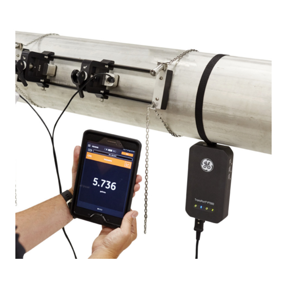
Chapter 2. Installation 2.5.1 A Sample Installation For reference, a typical completed PT900 installation is shown in Figure 6 below. PT900 Soft Transducer Chain Pair of CRR PT900 Pipe (Not Transmitter Strap Cable (x2) Transducers Fixture Provided) Flow Direction Spacing Important: Transducers shown on top of pipe for clarity only. -
Page 25: Transducer Spacing Calculation
Chapter 2. Installation 2.5.2 Transducer Spacing Calculation The required transducer spacing is calculated by ATTENTION! the APP after you program the PIPE, FLUID, TRANSDUCER and PLACEMENT menus. Before proceeding with this installation, you must complete the programming starting in Chapter 4. Programming on page 57 up to “Viewing the Transducer Spacing”... - Page 26 Chapter 2. Installation 2.5.3 Mounting the Clamp-On Fixture (cont.) Figure 8: Bracket Preliminary Setup Select a clamp-on fixture mounting location on the pipeline which meets the following requirements (see Figure 9 below): • A straight pipe run of at least 10 nominal pipe diameters (with no fittings or bends) before the upstream transducer •...
- Page 27 Chapter 2. Installation 2.5.3 Mounting the Clamp-On Fixture (cont.) Adjust the clamp-on fixture position so that the outer edge of the closest end piece is located at the chosen distance from the nearest inlet, outlet, joint or fitting in the pipeline (see Figure 10 below). >6”/150 mm Figure 10: Adjusting the Fixture Position Place the clamp-on fixture on top of the pipe so that minimal effort is...
- Page 28 Chapter 2. Installation 2.5.3 Mounting the Clamp-On Fixture (cont.) Verify that the pipe rests in the small cutout slot on the bottom of the end pieces (see Figure 12 below). Also, be sure that the scale markings on the rail rod of the clamp-on fixture can be easily read after the installation has been completed.
- Page 29 Chapter 2. Installation 2.5.3 Mounting the Clamp-On Fixture (cont.) Unscrew Chain Screw Mechanism End Flat End of Chain Step 6a Step 6b Chain Slot Press Down Tighten Insert Chain Step 6c Step 6d Figure 13: Installing a Chain ® TransPort PT900 User’s Manual...
- Page 30 Chapter 2. Installation 2.5.3 Mounting the Clamp-On Fixture (cont.) Repeat the previous steps to install the chain at the opposite end of the clamp-on fixture (see Figure 14 below). The clamp-on fixture should be firmly mounted to the pipe, but it should still be loose enough to allow final alignment.
- Page 31 Chapter 2. Installation 2.5.3 Mounting the Clamp-On Fixture (cont.) After final alignment is complete, fully tighten both chains by turning the nut on top of both chain screw mechanisms (see Figure 16 below) until the chain is tight enough to resist any fixture movement. Figure 16: Secure the Fixture to the Pipe Note: As the last two steps affect each other, repeat them until the fixture is both...
-
Page 32: Checking The Transducer Holders
A transducer holder is installed on each transducer by GE prior to shipment. Verify that your transducers have their holders already installed and that they are secure. If so, you may skip this section. -
Page 33: Installing The Transducers
Chapter 2. Installation 2.5.5 Installing the Transducers To install the transducers into the mounting bracket, complete the following steps: If necessary, loosen the thumb screw on the movable transducer clamp to permit axial positioning. Note that the fixed transducer clamp is set at the zero mark on the scale. Position the movable transducer clamp so that it aligns with the mark on the bracket’s graduated scale that matches the calculated transducer spacing. - Page 34 Chapter 2. Installation 2.5.5 Installing the Transducers (cont.) Move both cams to the loaded position, so that the clamp holders rest in their furthest radial position from the pipe (see Figure 19 below). Figure 19: Loaded Cams Apply the supplied couplant to both transducer faces (see Figure 20 below).
- Page 35 Chapter 2. Installation 2.5.5 Installing the Transducers (cont.) Slide a transducer, which is already locked into its transducer holder, into one of the clamp-on fixture’s clamp holders until the plunger from the top of the transducer holder snaps into its position on the bottom of the clamp holder (see Figure 21 below).
- Page 36 Chapter 2. Installation 2.5.5 Installing the Transducers (cont.) Release the cams on both transducer clamps so that the transducers are pushed towards the pipe to ensure that the couplant completely fills the gaps between the transducer faces and the pipe surface (see Figure 22 below).
-
Page 37: Even And Odd-Traverse Installations
Chapter 2. Installation 2.5.6 Even and Odd-Traverse Installations The transducers for a PT900 system may be installed in either of the following configurations: • Even-Traverse - The signal from one of the transducers traverses the fluid flow an even number of times before being received by the other transducer (two traverses is recommended for most applications). - Page 38 Chapter 2. Installation 2.5.6b Odd-Traverse Installations For an odd-traverse installation, the separate yoke included with the clamp-on fixture is required (see Figure 24 below). Yoke Screw Figure 24: Yoke for Odd-Traverse Installations Important: The clamping fixture must be installed before the yoke (see “Mounting the PT9 Clamp-On Fixture”...
- Page 39 Chapter 2. Installation 2.5.6b Odd-Traverse Installations (cont.) Place the yoke on the top of the pipe (see Figure 26 below). If the required transducer spacing is <305 mm/12 in., the yoke chain must be placed within the clamping fixture as shown. Figure 26: Yoke Placement On Top of Pipe Wrap the yoke chains around the pipe and secure them to the yoke bracket, as shown in Figure 27 below.
- Page 40 Chapter 2. Installation 2.5.6b Odd-Traverse Installations (cont.) Rotate the yoke until it is located in a horizontal position on the opposite side of the pipe from the previously installed clamping fixture, as shown in Figure 28 below. [Spacing >305 mm/12 in.] Bracket Surfaces [Spacing <305 mm/12 in.] Bracket Surfaces...
- Page 41 Chapter 2. Installation 2.5.6b Odd-Traverse Installations (cont.) Set the yoke axial position as follows: • Spacing >305 mm/12 in. (435 mm/17.13 in. is used as an example): Measure the required 435 mm/17.13 in. distance from the edge of the fixed clamp to the marked line on the yoke (see Figure 29 below). 17.13 in.
- Page 42 Chapter 2. Installation 2.5.6b Odd-Traverse Installations (cont.) Tighten the nuts to secure the yoke to the pipe (see Figure 31 below). Figure 31: Secure the Yoke Loosen the yoke screw. Then, apply couplant to the transducer face and insert the transducer into the yoke, as shown in Figure 32 below. Figure 32: Insert Transducer into Yoke ®...
- Page 43 Chapter 2. Installation 2.5.6b Odd-Traverse Installations (cont.) Tighten the yoke screw until the transducer firmly contacts the pipe. Your completed odd-traverse installation should look like Figure 33 below. [Spacing >305 mm/12 in.] [Spacing <305 mm/12 in.] Figure 33: Completed Odd-Traverse Installation (Top View) ®...
- Page 44 Chapter 2. Installation 2.5.6c Even-Traverse Installations (Spacing>305 mm/12 in.) For an even-traverse installation with a transducer spacing >305 mm/12 in., the separate yoke included with the clamp-on fixture is required (see Figure 34 below). Yoke Screw Figure 34: Yoke for Even-Traverse With S>305 mm/12 in. Important: The clamping fixture must be installed before the yoke (see “Mounting the PT9 Clamp-On Fixture”...
- Page 45 Chapter 2. Installation 2.5.6c Even-Traverse Installations (Spacing>305 mm/12 in.) (cont.) Place the yoke on the top of the pipe (see Figure 36 below). If the required transducer spacing is <305 mm/12 in., the yoke chain must be placed within the clamping fixture as shown. Figure 36: Yoke Placement On Top of Pipe Wrap the yoke chains around the pipe and secure them to the yoke bracket, as shown in Figure 37 below.
- Page 46 Chapter 2. Installation 2.5.6c Even-Traverse Installations (Spacing>305 mm/12 in.) (cont.) Rotate the yoke until it is located in a horizontal position on the same side of the pipe as the previously installed clamping fixture, as shown in Figure 38 below. Figure 38: Yoke Rotated into Horizontal Position Ensure that the top surfaces of the yoke bracket and the fixed clamping fixture bracket lie precisely in the same horizontal plane (see Figure 38...
- Page 47 Chapter 2. Installation 2.5.6c Even-Traverse Installations (Spacing>305 mm/12 in.) (cont.) Place the fixed clamp in the clamping fixture at zero on the scale. As an example, if the required transducer spacing is 435 mm/17.13 in., measure the required 435 mm/17.13 in. distance from the edge of the fixed clamp to the marked line on the yoke (see Figure 39 below).
- Page 48 Chapter 2. Installation 2.5.6c Even-Traverse Installations (Spacing>305 mm/12 in.) (cont.) Loosen the yoke screw. Then, apply couplant to the transducer face and insert the transducer into the yoke, as shown in Figure 41 below. Figure 41: Insert Transducer into Yoke Tighten the yoke screw until the transducer firmly contacts the pipe.
-
Page 49: Making The Electrical Connections
Chapter 2. Installation 2.6 Making the Electrical Connections Before taking measurements with the PT900, you must make all the necessary cable connections to the transmitter. To wire your transmitter, complete the following sections: • Connecting the Line Power (see page 33) •... - Page 50 Chapter 2. Installation 2.6.1 Connecting the Line Power (cont.) To ensure the safe operation, you must install and WARNING! operate the PT900 as described in this manual. Also, be sure to follow all applicable safety codes and regulations for installing electrical equipment in your area.
-
Page 51: Connecting The Transducers
Chapter 2. Installation 2.6.2 Connecting the Transducers To connect the transducers, see Figure 45 below and proceed as follows: Connect the cables from each of the transducers to the transmitter: Connect the transducer cable with the UP label on the cable connector to the transmitter connector labeled UP . -
Page 52: Connecting The Digital Output
Chapter 2. Installation 2.6.3 Connecting the Digital Output The PT900 provides one RS485/Modbus digital output and also supports a digital frequency/pulse output and a totalizer/control gate input. Connect the digital output as shown in Figure 46 below (see the cable to the right). The pin numbers for the connector and the color code for the standard input/output cable are shown in Table 1 below. -
Page 53: Connecting The Analog Inputs And Output
Chapter 2. Installation 2.6.4 Connecting the Analog Inputs and Output The PT900 provides one 0/4-20 mA analog current output and two 4-20 mA analog inputs, with a switchable 16 V supply for loop-powered temperature transmitters. Connect the analog inputs and output as shown in Figure 46 on page 36 (see the cable to the left). -
Page 54: Using The Usb Port
The PT900 comes with a self-contained, built-in, rechargeable battery pack to support portable operation. For optimum performance, these batteries require a minimum of maintenance. Use only GE-approved batteries and desktop CAUTION! chargers, which are designed to maximize battery life. Using other batteries or chargers voids your warranty and may cause damage to the equipment. -
Page 55: Charging And Storing The Batteries
Chapter 2. Installation 2.7.1 Charging and Storing the Batteries When you receive the PT900, you will need to initially charge the batteries. Also, the batteries may need to be recharged if they have not been used for a long period of time. -
Page 56: Replacing The Batteries
Chapter 2. Installation 2.7.2 Replacing the Batteries Replace the PT900 batteries only with the specified CAUTION! rechargeable batteries. The battery charges even when the unit is Off . Do not attempt to recharge non-rechargeable batteries. To replace the battery pack: Remove the rubber boot from the transmitter. -
Page 57: Disposing Of The Batteries
Be sure to dispose of your batteries properly. In CAUTION! some areas, battery disposal in business or household trash may be prohibited. For safe disposal options, contact your nearest GE authorized service center. 2.8 Powering On and Off To operate the PT900, the power cord must be plugged into line voltage or the battery pack must be charged as described in the previous sections. -
Page 58: Pt900 Led Indicators
Chapter 2. Installation 2.8 Powering On and Off (cont.) To turn the PT900 On , press the Power On/Off button on the top of the transmitter (see Figure 51 below) for about 3 seconds. Initially, only the Green Power LED shows solid On . -
Page 59: Power Led
Chapter 2. Installation 2.9.1 Power LED • Solid Green light when the meter is powered On • No light when the meter is Off • Blinking Green light when the meter is in power save mode 2.9.2 Bluetooth LED ® •... - Page 60 Chapter 2. Installation [no content intended for this page] ® TransPort PT900 User’s Manual...
-
Page 61: Chapter 3. Initial Setup
Before proceeding, make sure that both the PT900 Transmitter and the Tablet are fully charged. The AC power adapters are shipped in the carry case. If either the transmitter or the tablet cannot be powered On after charging, contact your GE representative or visit www.gemeasurement.com... -
Page 62: Installing Or Updating The Pt900 Android App
Google Play Store: To obtain a newer version of the APP from Google Play Store, search for “Transport PT900” and install it. Google Play Store is the preferred method of installation because updates will automatically be loaded to your tablet with the latest version of the application. -
Page 63: Installing The Tablet App From The Sd Card
Chapter 3. Initial Setup 3.3.3 Installing the Tablet APP from the SD Card To install the APP, complete the following steps: Open the “My Files” folder on the tablet screen and select the APP from the SD folder (see Figure 55 below). Figure 55: The “My Files”... - Page 64 Chapter 3. Initial Setup 3.3.3 Installing the Tablet APP from the SD Card (cont.) Click on the APK file, and the Android operating system will verify the checksum and signature for the file. Depending on whether this is an initial installation or an update installation, you will see one of the screens shown in Figure 57 below.
-
Page 65: Pairing The Tablet And The Transmitter
Chapter 3. Initial Setup 3.4 Pairing the Tablet and the Transmitter To set up the APP and pair with the PT900 transmitter, complete the following steps: After the APP has been downloaded to your tablet, find the icon shown in Figure 58 below on the tablet APPS and click on it to launch the APP. - Page 66 Chapter 3. Initial Setup 3.4 Setting Up the PT900 APP (cont.) At the screen shown in Figure 60 below, select the desired language for the APP and click OK . Figure 60: PT900 APP Language Options At the License Agreement screen (see Figure 61 below), read the agreement and then click AGREE to continue with the APP installation or click CANCEL to stop the APP installation.
- Page 67 Chapter 3. Initial Setup 3.4 Setting Up the PT900 APP (cont.) At the Registration screen (see Figure 62 below), click OK to register your PT900 or click CANCEL to skip the registration. Note: If you skip the registration, the screen will popup as a reminder the first five times you launch the APP and then it will never appear again.
- Page 68 Chapter 3. Initial Setup 3.4 Setting Up the PT900 APP (cont.) To connect to a new PT900 transmitter, click SCAN (see red arrow in Figure 64 below) and the APP will search for all available transmitters via Bluetooth. After the scan has been completed, any new transmitters which were found are listed in the AVAILABLE DEVICES section of the tablet screen (see red arrow in Figure 64 below).
- Page 69 Chapter 3. Initial Setup 3.4 Setting Up the PT900 APP (cont.) Note: In the Figure 64 on page 52, your PT900 transmitter is identified by the serial number on its label (see Figure 65 below). Figure 65: Transmitter Serial Number During the pairing process, PT900 security features require the user to confirm the pairing (see Figure 66 below).
- Page 70 Chapter 3. Initial Setup 3.4 Setting Up the PT900 APP (cont.) 10. Click the BACK button (shown at right) on the Android tablet to return to the PT900 APP. Then, select your PT900 transmitter in the TRANSMITTERS PAIRED list and click NEXT to open the Main Menu.
-
Page 71: Using The App Main Menu And The Slide Menu
Chapter 3. Initial Setup 3.5 Using the APP Main Menu and the Slide Menu 3.5.1 The Main Menu After successfully installing the APP on the tablet and pairing a PT900 transmitter with the tablet, the initial APP screen is the Main Menu shown in Figure 68 below. Figure 68: APP Main Menu Screen The available options in the APP Main Menu are: •... -
Page 72: The Slide Menu
Chapter 3. Initial Setup 3.5.2 The Slide Menu As an alternative to the Main Menu discussed in the previous section, you may use the Slide Menu shown in Figure 69 below. Click Here Swipe from left edge to right Figure 69: APP Slide Menu Screen To access the Slide Menu, either click the icon in the top left corner of the screen or swipe across the screen from the left edge to the right. -
Page 73: Chapter 4. Programming
Chapter 4. Programming Chapter 4. Programming 4.1 Configuring the Units of Measurement The UNITS OF MEASUREMENT menu (see Figure 70 below) allows the user to select the measurement units displayed by the PT900 in all of its screens. Note: Because the choice of Metric or English units is reflected in all other menu screens, this menu should be programmed first. - Page 74 Chapter 4. Programming 4.1 Configuring the Units of Measurement (cont.) From the APP side menu, click Unit Options under the PROGRAM menu. This will open the UNITS OF MEASUREMENT menu shown in Figure 70 on page 57. To program the UNITS OF MEASUREMENT , complete the following steps: Move the slide switch at the top of the menu to either Metric or English to select the desired PT900 global measurement units system.
-
Page 75: Configuring A Channel
Chapter 4. Programming 4.2 Configuring a Channel Selecting the PROGRAM>Channel option on the APP screen (see Figure 71 below) enables you to set up a channel for measuring flow rate. The PT900 supports up to two channels, channel 1 and channel 2 . They are programmed individually, and the programmed information can be saved in a PRESETS file. - Page 76 Chapter 4. Programming 4.2 Configuring a Channel (cont.) Using Channel 1 as an example, refer to Figure 72 below and complete the following steps: Change the channel status from Off to On . This will not only activate the channel, but it will also activate the two programming buttons. If the other channel has already been programmed, click the COPY CH button to copy all programming data from the other channel to the current channel.
-
Page 77: Programming The Pipe Menu
Chapter 4. Programming 4.3 Programming the PIPE Menu The PIPE menu allows the user to specify all pipe parameters that are required to ensure accurate ultrasonic flow rate measurements. An example of this menu is shown in Figure 73 below. See the following sub-sections for the options available in programming the various pipe parameters. -
Page 78: Pipe Materials
Chapter 4. Programming 4.3.1 Pipe Materials From the drop-down list of pipe materials supported by the PT900 transmitter, select the pipe material for your application. For convenient reference, some of the available options are shown in Table 3 below. Table 3: Pipe Materials Material Description Material... -
Page 79: Pipe Lining
Chapter 4. Programming 4.3.3 Pipe Lining If you entered YES in the LINING box, the LINING MATERIAL , LINING SOUND SPEED and LINING THICKNESS must be programmed to ensure accurate flow rate measurements. From the drop-down list of pipe linings supported by the PT900 transmitter, select the pipe lining for your application. -
Page 80: Programming The Fluid Menu
Chapter 4. Programming 4.4 Programming the FLUID Menu The FLUID menu allows the user to specify all the parameters of the fluid flowing through the pipe that are required to ensure accurate ultrasonic flow rate measurements. An example of this menu is shown in Figure 74 below. See the following sub-sections for the options available in programming the various fluid parameters. - Page 81 If you selected OTHER as the FLUID , the automatic entry in the SOUND SPEED box must be changed to the correct value by user. The fluid KINEMATIC VISCOSITY (see GE document 916-119) is used to calculate the Reynolds Number, which is then used calculate the Reynolds Correction.
-
Page 82: Programming The Transducers Menu
Chapter 4. Programming 4.5 Programming the TRANSDUCERS Menu The TRANSDUCERS menu allows the user to specify all the parameters of the transducers that are required to ensure accurate ultrasonic flow rate measurements. An example of this menu is shown in Figure 75 below. See the following sub-sections for the options available in programming the transducers. -
Page 83: Programming The Transducer Parameters
See Table 6 below for the transducer types suitable for use with the PT900. Note: The GE Transducer Installation Guide for your transducer model provides more detailed information on transducer mounting configurations. Table 6: Available Clamp-On Transducers... - Page 84 The TW parameter is the time the transducer signal spends traveling through the transducer and the transducer cable. Enter the value provided by GE with your transducer. ® TransPort PT900 User’s Manual...
-
Page 85: Setting The Reynolds Correction Factor
WEDGE SOUND SPEED: This parameter is entered automatically by the PT900 for all Standard transducers, but it must be edited with the correct value provided by GE for Other transducers. WEDGE TEMPERATURE: This parameter must be entered manually for all transducers. -
Page 86: Programming The Meter Factor
Chapter 4. Programming 4.5.3 Programming the Meter Factor To program the METER FACTOR , refer to Figure 75 on page 66 and complete the following steps: Click on the METER FACTOR button to open the menu shown in Figure 77 below. - Page 87 Chapter 4. Programming 4.5.3 Programming the Meter Factor (cont.) Use the slide switch to set the K-FACTOR to either Single or Table . The, proceed to the appropriate step below: • SINGLE: A single multiplier is applied to all PT900 measurements. Generally, if the Reynolds Correction Factor is On , the K-FACTOR should be set to 1.00.
-
Page 88: Programming The Placement Menu
Chapter 4. Programming 4.6 Programming the PLACEMENT Menu The PLACEMENT menu allows the user to configure the mounting method of the transducers, based on the programmed information in the TRANSDUCERS menu (see “Programming the TRANSDUCERS Menu” on page 66). 4.6.1 Viewing the Traverse Configuration For CLAMP-ON transducers, one of the six possible TRAVERSE configurations shown in Figure 79 below is displayed, as appropriate for your programmed transducer information. -
Page 89: Viewing The Transducer Spacing
Chapter 4. Programming 4.6.2 Viewing the Transducer Spacing The TRANSDUCER SPACING screen (see Figure 80 below) shows the value calculated by the PT900 for the correct distance between the upstream and downstream transducers, based on your programmed transducer data. This value should be used when installing your transducer clamping fixture on the pipe. - Page 90 Chapter 4. Programming 4.6.2a Custom Transducer Spacing If your transducers were installed with a spacing different from the value calculated by the APP, refer to Figure 81 below and input the actual spacing as follows: Note: Be sure that, if the installed spacing you input is larger than the calculated value, it is not more than 10% above the calculated value.
- Page 91 Chapter 4. Programming 4.6.2b Zero Flow Validation Important: You must make sure that the fluid in your pipe is not flowing before proceeding. After the flow in the pipeline is verified to be static, refer to Figure 82 below and calibrate the zero flow setting by completing the following steps: Click the VELOCITY input control.
- Page 92 Chapter 4. Programming 4.6.2c Sound Speed Validation When the speed of sound in your fluid does not equal published values, refer to Figure 83 below and set the SOUND SPEED LEVEL by completing the following steps: Click the SOUND SPEED LEVEL input control. Enter your actual sound speed in the units specified by your system UNITS setting.
-
Page 93: Configuring The Program Options
Chapter 4. Programming 4.7 Configuring the Program Options Note: The programming instructions in this section are only required if you will be using any of the options listed below. From the APP side menu, click the Program Options sub-menu under the PROGRAM menu, as highlighted in Figure 84 below. - Page 94 Chapter 4. Programming 4.7 Configuring the Program Options (cont.) Figure 85: The Program Options Menu ® TransPort PT900 User’s Manual...
-
Page 95: Programming The Energy Tab
Chapter 4. Programming 4.7.1 Programming the ENERGY Tab The first tab in the Program Options menu is ENERGY (see Figure 85 on page 78). The ENERGY tab enables the user to calculate the energy of a system based on the temperature at a supply point, the temperature at a return point and the flow of the fluid through the system. - Page 96 Chapter 4. Programming 4.7.1 Programming the ENERGY Tab (cont.) In the CH1 DENSITY and CH2 DENSITY sections, open the drop-down list and select either Fixed or Active as the source of the fluid density used for all calculations made for the channel. If you choose Fixed , you will need to enter the desired value.
-
Page 97: Programming The Inputs Tab
Chapter 4. Programming 4.7.2 Programming the INPUTS Tab The INPUTS tab (see Figure 86 below) enables the user to specify the parameters for the energy supply temperature, the energy return temperature and the fixed temperature, based on your previous programming choices in the ENERGY tab. Figure 86: The Inputs Menu To configure ANALOG INPUTS A , proceed as follows: If either the SUPPLY TEMPERATURE or the RETURN TEMPERATURE has... -
Page 98: Programming The Outputs Tab
Chapter 4. Programming 4.7.2 Programming the INPUTS Tab (cont.) If General Purpose is chosen in the FUNCTION box, enter the correct ZERO and SPAN values in the appropriate boxes. Program ANALOG INPUTS B using the same steps described for ANALOG INPUTS A . 4.7.3 Programming the OUTPUTS Tab The OUTPUTS tab (see Figure 87 below) enables the user to specify the ANALOG OUTPUTS... - Page 99 Chapter 4. Programming 4.7.3a Analog Outputs To program the ANALOG OUTPUTS , complete the following steps: Open the drop-down list in the MEASUREMENT box, and select either CH1 (Channel 1), CH2 (Channel 2), Average (Average of CH1 and CH2) or General (General Function List) for the output.
- Page 100 Chapter 4. Programming 4.7.3a Analog Outputs (cont.) In the ZERO box, enter the value which corresponds to a 4 mA output. In the SPAN box, enter the value which corresponds to a 20 mA output. Open the drop-down list in the ERROR HANDLING box, and select how the PT900 should handle an analog output fault condition.
- Page 101 Chapter 4. Programming 4.7.3b Digital Outputs (cont.) If Frequency was selected in the FUNCTION box: • Open the drop-down list in the MEASUREMENT box, and select either CH1 (Channel 1), CH2 (Channel 2), Average (Average of CH1 and CH2) or General (General Function List) for the output. •...
- Page 102 Chapter 4. Programming 4.7.3b Digital Outputs (cont.) If Gate was selected in the FUNCTION box, no additional programming is required. Note: Gate is used to synchronize the totalizer with the meter calibration system. The gate stops and starts the meter totalizer, so that the user can compare the totalizer value with the measured volume of water in a tank.
-
Page 103: Programming The User Functions Tab
Chapter 4. Programming 4.7.4 Programming the USER FUNCTIONS Tab The USER FUNCTIONS tab (see Figure 88 below) enables the user to program mathematical equations which perform custom calculations on meter measurements. For example, any standard meter parameter can be used to calculate a new custom parameter. - Page 104 Chapter 4. Programming 4.7.4 Programming the USER FUNCTIONS Tab (cont.) To program the USER FUNCTIONS , complete the following steps: Open the drop-down list in the FUNCTION box, and select the desired function number ( User Func 1 through User Func 5 ). In the LABEL box, enter a name for the function.
- Page 105 Chapter 4. Programming 4.7.4 Programming the USER FUNCTIONS Tab (cont.) Define a User Table by completing the following steps: Open the drop-down list in the TABLE box, and select a table number ( Table 1 through Table 4 ). b. In the LABEL box, enter a name for the table. Click the EDIT TABLE button to open a blank table, as shown in Table 11 below.
- Page 106 Chapter 4. Programming [no content intended for this page] ® TransPort PT900 User’s Manual...
-
Page 107: Chapter 5. Measurements
Chapter 5. Measurements Chapter 5. Measurements 5.1 Introduction The PT900 is a transit-time ultrasonic flow meter. During signal processing, many different system parameters are measured or calculated. The PT900 APP provides the user a powerful tool for monitoring these parameters in real-time. From the initial APP screen, click on the MEASURE icon to display a screen similar to Figure 89 below. -
Page 108: Setting Up The Measurements For Display
Chapter 5. Measurements 5.2 Setting Up the Measurements for Display The PT900 APP can display up to 10 different variables at the same time. To set up your display screen, click the EDIT button at the top right of the measurement screen to open the SET UP MEASUREMENTS menu, as shown in Figure 90 below. - Page 109 Chapter 5. Measurements 5.2 Setting Up the Measurement Screen (cont.) Table 12: Available Measurement Variables Standard Variables Channel 1 & Channel 2 AVE (Average) GEN (General) Velocity Velocity AI 1 Current Volumetric Volumetric AI 2 Current Standard Volumetric Standard Volumetric AI 1 Value Mass Mass...
-
Page 110: Viewing Measurements
Chapter 5. Measurements 5.2 Setting Up the Measurement Screen (cont.) To delete a measurement from the measurement set, click the button to the right of the desired measurement. Note that the number of measurements currently in the list and the maximum allowed number of measurements (10) are displayed. -
Page 111: Displaying Multiple Measurements
Chapter 5. Measurements 5.3 Viewing Measurements (cont.) Clicking any measurement on the measurement screen will open a popup dialog box for changing the decimal format for that measurement (see Figure 92 below). Select the desired decimal format from the drop-down list. Select the desired number of decimal places from the drop-down list. -
Page 112: Displaying A Single Measurement
Chapter 5. Measurements 5.3.2 Displaying a Single Measurement To change the screen to a one-measurement display (see Figure 93 below), click the icon. In this mode, one measurement is displayed at a time and you can switch between available measurements by swiping across the screen left or right. Click Here Figure 93: Single Measurement Screen ®... - Page 113 Chapter 5. Measurements 5.3.2 Displaying a Single Measurement (cont.) Note the following: • The default one-measurement display is the numeric value of the real-time measurement, as shown in Figure 93 on page 96. • To switch the display to GRAPH mode, click the icon at the top right of the screen.
- Page 114 Chapter 5. Measurements 5.3.2 Displaying a Single Measurement (cont.) • When in GRAPH mode, click the SETTING button just above the graph to open the SET Y AXIS menu shown in Figure 95 below. Figure 95: Graph Parameters Menu To edit the parameters for the Y axis, complete the following steps: Move the slide switch to Manual .
-
Page 115: Displaying The Totalizer Screen
Chapter 5. Measurements 5.3.3 Displaying the Totalizer Screen The Batch Totalizer is used for measuring the total volume of fluid which passes the measurement point over a period of time. This can be done automatically by using the external Digital Output Gate (see “Digital Outputs” on page 84) or it can be done manually. -
Page 116: Displaying The Diagnostics Parameters
Chapter 5. Measurements 5.3.4 Displaying the Diagnostics Parameters During operation, the PT900 measures various system parameters for the purpose of analyzing the system performance. These system diagnostic parameters are listed in the DIAGNOSTICS measurement screen (see Figure 97 below). To access this screen, click the icon at the top of the measurement screen. -
Page 117: Chapter 6. Logging Data
Chapter 6. Logging Data Chapter 6. Logging Data 6.1 Introduction The PT900 transmitter supports an easy-to-use data logging function, which allows diagnostic and measurement data to be recorded in a log file. To create a log file, the following parameters must be specified: •... -
Page 118: Adding A Log
Chapter 6. Logging Data 6.2 Adding a Log The LOG function can be accessed from the APP side bar menu or from the PROGRAM menu. When you enter the LOG function for the first time, you will see the message shown in Figure 98 below. Figure 98: Initial Log Screen Important: Before creating a new log, be sure to synchronize the transmitter and... - Page 119 Chapter 6. Logging Data 6.2 Adding a Log (cont.) Program the new log parameters as shown in Table 13 below: Table 13: Programming the Log Parameters Parameter Entry Type Description LOG NAME: Manual entry 11 characters maximum FORMAT: Slide switch Linear: Record all values from start time to end time...
-
Page 120: Deleting, Stopping Or Editing A Log
Chapter 6. Logging Data 6.3 Deleting, Stopping or Editing a Log In the LOGS main menu (see Figure 100 below), all existing logs and their current status are listed. Each listed log may be edited, stopped or deleted, depending on their current status. -
Page 121: Deleting A Log
Chapter 6. Logging Data 6.3.1 Deleting a Log To DELETE a Pending or Stopped log, complete the following steps: On the LOGS main menu (see Figure 100 on page 104), click in the SELECT column to the right of the log you wish to delete. Verify that the icon is shown to the right of the log you wish to delete. -
Page 122: Editing A Log
Chapter 6. Logging Data 6.3.2 Editing a Log To EDIT a Pending log, complete the following steps: On the LOGS main menu (see Figure 100 on page 104), click in the SELECT column to the right of the log you wish to edit. Verify that the icon is shown to the right of the log you wish to stop. -
Page 123: Viewing A Log
Chapter 6. Logging Data 6.3.3 Viewing a Log The logged data is stored in the PT900 transmitter. This data can be accessed from a PC via a USB connection. To view a log, complete the following steps: Be sure the transmitter and tablet time settings are synchronized by setting the transmitter time in the TRANSMITTER >... - Page 124 Chapter 6. Logging Data [no content intended for this page] ® TransPort PT900 User’s Manual...
-
Page 125: Chapter 7. Configuring The Transmitter
Chapter 7. Configuring the Transmitter Chapter 7. Configuring the Transmitter 7.1 Introduction To configure the PT900 transmitter, click the TRANSMITTER icon in the side bar menu to open the TRANSMITTER menu (see Figure 102 below). Figure 102: The Transmitter Menu ®... - Page 126 Chapter 7. Configuring the Transmitter 7.1 Introduction (cont.) If a PT900 transmitter is CONNECTED to the tablet APP via Bluetooth, the TRANSMITTER menu shows device information about the PT900 transmitter, the battery and the memory usage. However, if the connection is OFFLINE , this information is unavailable.
- Page 127 Chapter 7. Configuring the Transmitter 7.1 Introduction (cont.) • The BATTERY section shows the remaining battery time for an ONLINE transmitter (not available for an OFFLINE transmitter). • The STORAGE section shows the current memory usage for Logs and Presets and the remaining unused embedded storage memory for an ONLINE transmitter (not available for an OFFLINE transmitter).
-
Page 128: Updating The Pt900 Transmitter Software
Chapter 7. Configuring the Transmitter 7.2 Updating the PT900 Transmitter Software To update the PT900 transmitter software, complete the following steps: Obtain the image file ( ipl-ifs-PT900_vx.x.xx_svnxxx.bin ) for the new PT900 software version. Rename the new image file as image.bin . Copy the new image.bin file to the PT900 from a PC, using a USB cable as shown in Figure 104 below. - Page 129 Chapter 7. Configuring the Transmitter 7.2 Updating the PT900 Software (cont.) In the APP TRANSMITTER menu, click the UPDATE button (see Figure 106 below) to start the update. Figure 106: UPDATE Button in TRANSMITTER Menu The system will check the validation of the new image file by checksum. If the check is OK , the new software will load in the next reboot.
- Page 130 Chapter 7. Configuring the Transmitter 7.2 Updating the PT900 Software (cont.) The update will take about 30 seconds to complete, and the screen shown in Figure 108 below will be displayed during the update. Figure 108: Update in Progress Screen After the transmitter reboots, the message shown in Figure 109 below will pop up.
-
Page 131: Programming The Transmitter Service Menu
Chapter 7. Configuring the Transmitter 7.3 Programming the Transmitter SERVICE Menu The transmitter SERVICE menu includes the following sub-menus: • CALIBRATION (see page 115) • (see page 118) METER SETUP • TESTING (see page 121) • ERROR LIMITS (see page 124) 7.3.1 Programming the CALIBRATION Menu The CALIBRATION option (see Figure 110 below) is used to calibrate the transmitter’s ANALOG OUTPUT and the ANALOG INPUT . - Page 132 Chapter 7. Configuring the Transmitter 7.3.1a Calibrating the Option ANALOG OUTPUT To calibrate the transmitter ANALOG OUTPUT , refer to Figure 111 below and complete the following steps: Click the CALIBRATE button to open the ANALOG OUTPUT CALIBRATION menu. Move the slide switch to the 4 mA position. In the Actual 4 mA text box, enter the output current actually measured with a digital ammeter at the transmitter’s analog output.
- Page 133 Chapter 7. Configuring the Transmitter 7.3.1b Calibrating the Option ANALOG INPUT To calibrate the transmitter ANALOG INPUT , refer to Figure 112 below and complete the following steps: Click the CALIBRATE button to open the ANALOG INPUT CALIBRATION menu. Move the first slide switch to the AI 1 position. Connect a 4 mA calibrated current source to the transmitter’s analog input.
-
Page 134: Programming The Meter Setup Menu
Chapter 7. Configuring the Transmitter 7.3.2 Programming the METER SETUP Menu The METER SETUP option (see Figure 113 below) is used to configure the following PT900 system parameters (see the following section for instructions): • • TOTALIZER POWER SAVING TIME •... - Page 135 Chapter 7. Configuring the Transmitter 7.3.2a Programming the TOTALIZER Option The TOTALIZER option enables the user to reset the values of all batch and inventory totalizers (i.e., Forward Totalizer, Reverse Totalizer, Net Totalizer and Totalizer Time) in all channels to zero by clicking the RESET button. The RESPONSE option enables the user to choose the time interval in seconds between any two measurements: •...
- Page 136 Chapter 7. Configuring the Transmitter 7.3.2c Programming the PEAK DETECT Option From the drop-down list in the PEAK DETECT option, select the desired method for identifying the peak of the received signal. The following options are available: • The PEAK method is no longer available. •...
-
Page 137: Programming The Testing Menu
Chapter 7. Configuring the Transmitter 7.3.3 Programming the TESTING Menu The TESTING menu (see Figure 114 below) is used to ensure that the PT900 is performing properly. The following tests are included: • WATCHDOG METER • WAVE SAMPLE CHANNEL Figure 114: The TESTING Menu ®... - Page 138 Chapter 7. Configuring the Transmitter 7.3.3a Running the Watchdog Test The PT900 transmitter includes a Watchdog Timer Circuit . This circuit automatically resets the transmitter. Proceed as follows: Click the RUN TEST button in the TESTING menu (see Figure 114 on page 121).
- Page 139 Testing with the Wave Sample Channel The WAVE SAMPLE CHANNEL test captures signals and displays them in a graph similar to Figure 116 below. Important: Wave samples are only required for troubleshooting with GE’s guidance. Figure 116: Wave Sample Channel Capture ®...
-
Page 140: Programming The Error Limits Menu
Chapter 7. Configuring the Transmitter 7.3.4 Programming the ERROR LIMITS Menu The ERROR LIMITS menu (see Figure 117 below) enables the user to set limits for an incoming signal. When the signal falls outside these programmed limits, an error indication is displayed on the MEASUREMENT screen. Figure 117: The ERROR LIMITS Menu ®... - Page 141 Chapter 7. Configuring the Transmitter 7.3.4 Programming the ERROR LIMITS Menu (cont.) To program the ERROR LIMITS menu, complete the following steps: In the VELOCITY section, enter the desired MIN LIMIT and MAX LIMIT values in the appropriate text boxes. If the measured velocity is outside these limits, the E3: VELOCITY RANGE message is displayed on the measurement screen.
- Page 142 Chapter 7. Configuring the Transmitter 7.3.4 Programming the ERROR LIMITS Menu (cont.) There is an acceptable range for each of the parameters entered in this menu. If you enter a value outside of these limits a message similar to Figure 118 below is displayed. Figure 118: Out of Limits Message Click the OK button to close the above message, then click the icon...
-
Page 143: Chapter 8. Error Codes And Troubleshooting
Chapter 8. Error Codes and Troubleshooting Chapter 8. Error Codes and Troubleshooting 8.1 Error Codes The bottom line of the Tablet LCD displays a single, top-priority error message during operation. This line, called the Error Line and it includes the following: •... - Page 144 Chapter 8. Error Codes and Troubleshooting 8.1.2b E2: Sound Speed Error Problem: The sound speed exceeds the programmed limits. Cause: This error may be caused by incorrect programming, poor flow conditions or poor transducer orientation. Action: Correct the programming errors. Be sure to check the programmed Error Limits value.
-
Page 145: Diagnostics
Read the following sections carefully to determine if the problem is indeed related to the fluid or pipe. If the instructions in this section fail to resolve the problem, contact GE for assistance. ®... - Page 146 Chapter 8. Error Codes and Troubleshooting 8.2.2a Fluid Problems Most fluid-related problems result from a failure to observe the flow meter system installation instructions. Refer to Chapter 2, Installation, to correct any installation problems. If the physical installation of the system meets the recommended specifications, it is possible that the fluid itself may be preventing accurate flow rate measurements.
- Page 147 Chapter 8. Error Codes and Troubleshooting 8.2.2b Pipe Problems Pipe-related problems may result either from a failure to observe the installation instructions in Chapter 2, Installation, or from improper programming of the meter. By far, the most common pipe problems are the following: •...
-
Page 148: Diagnostic Parameters
8.2.2c Transducer Problems Ultrasonic transducers are rugged, reliable devices. However, they are subject to physical damage from mishandling and chemical attack. Contact GE for assistance if you cannot solve a transducer-related problem. 8.3 Diagnostic Parameters If you suspect fluid, pipe, transducer or electrical problems with your PT900 system, the diagnostic parameters listed in Table 16 below are available to help you troubleshoot the problem. -
Page 149: Getting Help
Service (see page 136) • Spare Parts (see page 137) Figure 119: The HELP Menu Important: Please contact your GE sales representative at any time for help with any questions not answered in this manual. ® TransPort PT900 User’s Manual... -
Page 150: The About Screen
Chapter 8. Error Codes and Troubleshooting 8.4.1 The About Screen Click on the About option to open a screen similar to Figure 120 below. This screen displays general information about the PT900 system. This information includes: model name, instrument type, software version, and the copyright year of the APP. Figure 120: The About Screen ®... -
Page 151: The Diagnostics Screen
Chapter 8. Error Codes and Troubleshooting 8.4.2 The Diagnostics Screen Click on the Diagnostics option to open a screen similar to Figure 121 below. This screen displays the possible flow errors that can be generated by the PT900 system, such as the E1:Low Signal error shown in the example below. Just click on any of the listed error codes to display a description of that error. -
Page 152: The Service Screen
Chapter 8. Error Codes and Troubleshooting 8.4.3 The Service Screen Click on the Service option to open a screen similar to Figure 122 below. This screen provides links to the many services provided by GE for the PT900. Figure 122: The Service Screen ®... -
Page 153: The Spare Parts Screen
Click on the Spare Parts option to open a screen similar to Figure 123 below. This screen lists the spare parts available from GE for the PT900 system. Just click on any of the listed parts to display a description of that part. -
Page 154: Help Topics List
Chapter 8. Error Codes and Troubleshooting 8.5 Help Topics List The following is a complete list of the available help topics: What type of tablet may I use with the PT900 Applications? Where can I get the PT900 application? To update to the latest version of the PT900 APP, do I need to update both my APP and PT900 firmware? I cannot connect to the PT900 transmitter with my tablet. - Page 155 Chapter 8. Error Codes and Troubleshooting 8.5 Help Topics List (cont.) 20. What is wedge temperature and what temperature should I use? 21. What is Reynolds Correction Factor and should it be programmed or Off ? 22. What is Calibration Factor and should it be programmed On or Off ? 23.
-
Page 156: The Quick-Start Guide
The Quick Start Guide, which can be found on your SD card, provides general instructions on using the flow meter and the APP. Start by watching the installation videos on GE web site at www.gemeasurement.com/pt900 , and then complete the following steps: Check the PT900 transmitter and the tablet before use. -
Page 157: Chapter 9. Communication
Chapter 9. Communication Chapter 9. Communication 9.1 Modbus Communication In general, the PT900 flow meter follows the standard Modbus communications protocol defined by the reference MODBUS APPLICATION PROTOCOL SPECIFICATION V1.1b . This specification is available at www.modbus.org . With this reference as a guide, the user may use any Modbus master to communicate with the flow meter. - Page 158 Chapter 9. Communication Table 17: Modbus Register Map (cont.) Register Register Access Description Format (in Hex) (in Dec.) Level 1284 User Global Unit group 3 for dB RW INT32 1286 User Global Unit group 4 for Density RW INT32 1288 User Global Unit group 5 for Diamention RW INT32...
- Page 159 Chapter 9. Communication Table 17: Modbus Register Map (cont.) Register Register Access Description Format (in Hex) (in Dec.) Level 1830 remaining battery life (minutes). RO INT32 1832 remaining time until Battery reaches full RO INT32 charge (minutes). 1834 the cell-pack's internal temperature (°C) RO INT32 1836 the cell-pack voltage (mV)
- Page 160 Chapter 9. Communication Table 17: Modbus Register Map (cont.) Register Register Access Description Format (in Hex) (in Dec.) Level 3584 Analog Out Measurement Value RO (IEEE 32 bit) 3586 Digital Out 1 Pulse Measurement Value RO (IEEE 32 bit) 3588 Digital Out 1 Frequency Measurement Value RO (IEEE 32 bit) 3590 Digital Out 1 Alarm Measurement Value...
- Page 161 Chapter 9. Communication Table 17: Modbus Register Map (cont.) Register Register Access Description Format (in Hex) (in Dec.) Level 20E0 20E0 8416 User Zero Cutoff RW (IEEE 32 bit) 20E2 8418 User DeltaT Offset RW (IEEE 32 bit) 20E4 8420 User the inputted threshold under manual mode RW (IEEE 32 bit)
- Page 162 Chapter 9. Communication Table 17: Modbus Register Map (cont.) Register Register Access Description Format (in Hex) (in Dec.) Level 2418 9240 User Ch1 Fluid Static Density RW (IEEE 32 bit) 241A 9242 User Ch1 Fluid Reference Density RW (IEEE 32 bit) 241C 9244 User...
- Page 163 Chapter 9. Communication Table 17: Modbus Register Map (cont.) Register Register Access Description Format (in Hex) (in Dec.) Level 264E 9806 Ch1 inventory totals time RO (IEEE 32 bit) 2680 2680 9856 Ch1 Transit Time Up RO (IEEE 32 bit) 2682 9858 Ch1 Transit Time Dn...
- Page 164 Chapter 9. Communication Table 17: Modbus Register Map (cont.) Register Register Access Description Format (in Hex) (in Dec.) Level 281A 10266 User Ch2 Fluid Reference Density RW (IEEE 32 bit) 281C 10268 User Ch2 Fluid Temperature RW (IEEE 32 bit) 281E 10270 User...
- Page 165 Chapter 9. Communication Table 17: Modbus Register Map (cont.) Register Register Access Description Format (in Hex) (in Dec.) Level 2A80 2A80 10880 Ch2 Transit Time Up RO (IEEE 32 bit) 2A82 10882 Ch2 Transit Time Dn RO (IEEE 32 bit) 2A84 10884 Ch2 DeltaT...
-
Page 166: Bluetooth Communication
Chapter 9. Communication Table 17: Modbus Register Map (cont.) Register Register Access Description Format (in Hex) (in Dec.) Level 3104 12548 User eFlowMeasure RW INT32 3106 12550 User eEnthalpyCalc RW INT32 3108 12552 User eSupplyTemp RW INT32 310A 12554 User eReturnTemp RW INT32 310C... -
Page 167: Appendix A. Specifications
3 in. (76.2 mm) Pipe Material All metals and most plastics Consult GE for concrete, composite materials and highly corroded or lined pipes. Accuracy ±1% of reading (2in./50mm or greater pipe sizes) ±2% of reading (0.5in./15mm to <2in./50mm pipe sizes) Installation assumes a fully developed symmetrical flow profile (typically 10 pipe diameters upstream and 5 pipe diameters downstream of straight pipe run). -
Page 168: Pt900 Flow Transmitter
Appendix A. Specifications A.2 PT900 Flow Transmitter Enclosure IP65 rating Specifications Weight: 3 lb (1.4 kg) Size (h x w x md): 7.9 x 4.3 x 1.5 in. (200 x 109 x 38 mm) Mounting: Soft strap around pipe or magnetic clamp Analog Inputs 4-20 mA (qty 2) Analog Output... -
Page 169: User Interface
English, Arabic, Chinese (Simplified), Dutch, French, German, Italian, Japanese, Korean, Portuguese, Russian, Spanish, Swedish, Turkish Installing the PT900 APP • File provided on SD card • Free download from Google Play Store • Free download from GE website (QR code available) ® TransPort PT900 User’s Manual... -
Page 170: Clamp-On Transducers
Appendix A. Specifications A.5 Clamp-On Transducers Temperature Range* Standard: -40 to 302°F (-40 to 150°C) Optional: -328 to 752°F (-200 to 400°C) *See individual transducer model specifications for exact temperature range Mounting • New PT9 clamping fixture for pipes ≥2 in. (50 mm) •... -
Page 171: Options
Temperature Transmitter: loop-powered, 4-wire PT1000 surface-mount RTDs, NIST-certified • Accuracy: ±0.12°C (±0.22°F) of reading • Range: 0 to 149°C (32 to 300°F) standard GE PocketMike Thickness Gauge • Compact stainless steel design, IP67 • Pivoting, high-contrast LCD display • Easy operation via four keys •... - Page 172 Appendix A. Specifications [no content intended for this page] ® TransPort PT900 User’s Manual...
-
Page 173: Service Records
Appendix B. Data Records Appendix B. Data Records B.1 Service Record Whenever any service procedure is performed on the PT900 flow meter, the details of the service should be recorded in this appendix. An accurate service history of the meter can prove very helpful in troubleshooting any future problems. Record the complete and detailed service data for the PT900 in Table 18 below. -
Page 174: Initial Settings
Appendix B. Data Records B.2 Initial Settings The values for the parameter settings immediately after initial installation of the meter and verification of proper operation should be entered in Table 19 below. Table 19: Initial System Parameter Settings Parameter Initial Value Pipe OD Pipe ID Pipe Wall Thickness... -
Page 175: Initial Diagnostic Parameters
Appendix B. Data Records B.3 Initial Diagnostic Parameters The values for the transducer signal diagnostic parameters immediately after initial installation of the meter and verification of proper operation should be entered in Table 20 below. These initial values can then be compared to current values to help diagnose any future malfunction of the system. - Page 176 Appendix B. Data Records Table 20: Initial Diagnostic Parameters (cont.) Parameter Initial Value ActiveTW Up ActiveTW Dn Gain Up Gain Dn Error Status Reported Error Peak Up Peak Dn Peak % Up Peak % Dn ® TransPort PT900 User’s Manual...
- Page 177 Index About Screen ........... . 134 Adding a Log .
- Page 178 Index Cable Requirements ..........155 Calibrate Factor .
- Page 179 Index Display Decimal Format..........95 Diagnostic Parameters.
- Page 180 Index Fluid Available Types ..........65 Density Table .
- Page 181 Index Logs Adding ............102 Configuring .
- Page 182 Index Modbus Communication..........141 Configuring Output.
- Page 183 Registration, GE Product ........
- Page 184 GE Services........
- Page 185 Index Transducers Couplant, Applying ..........18 Holders .
- Page 186 Index USER FUNCTIONS Menu ......... . 87 User Functions Operators.
- Page 187 GE Sensing. Fuses and batteries are specifically excluded from any liability. This warranty is effective from the date of delivery to the original purchaser. If GE Sensing determines that the equipment was defective, the warranty period is: •...
- Page 188 2. If GE Sensing instructs you to send your instrument to a service center, it must be shipped prepaid to the authorized repair station indicated in the shipping instructions.
- Page 190 Customer Support Centers U.S.A. The Boston Center 1100 Technology Park Drive Billerica, MA 01821 U.S.A. Tel: 800 833 9438 (toll-free) 978 437 1000 E-mail: sensing@ge.com Ireland Sensing House Shannon Free Zone East Shannon, County Clare Ireland Tel: +35 361 470200 E-mail: gesensingsnnservices@ge.com An ISO 9001:2008 Certified Company www.gemeasurement.com/quality-certifications...