
Related Manuals for Honeywell MC ToolKit

Summary of Contents for Honeywell MC ToolKit
-
Page 1: User Manual
MC ToolKit User Manual Doc. No.: 34-ST-25-20 Release: Last Revision Date: 9/06 Release 3 34-ST-25-20 MC Toolkit User Manual 9/06... - Page 2 However, we assume no responsibility for its use. While we provide application assistance personally, through our literature and the Honeywell web site, it is up to the customer to determine the suitability of the product in the application.
-
Page 3: About This Document
About This Document Contacts World Wide Web The following lists Honeywell’s World Wide Web sites that will be of interest to our industrial automation and control customers. Honeywell Organization WWW Address (URL/e-mail) Corporate http://www.honeywell.com Industrial Measurement and Control http://content.honeywell.com/imc/ International http://www.honeywell.com/Business/global.asp... - Page 4 Chassis Ground. Identifies a connection to the chassis or frame of the equipment shall be bonded to Protective Earth at the source of supply in accordance with national and local electrical code requirements. Page iv 34-ST-25-20 MC Toolkit User Manual Release 3 9/06...
-
Page 5: Table Of Contents
Transmitter/Communications Characteristics..................4 Honeywell Transmitter (Analog Mode) ....................4 General Procedures ....................10 Overview............................10 Primer for MC Toolkit & SDC 625 Application Software ..............10 Start-Up and Basic Operation and Navigation................10 Input Methods: Letter, Numbers, Symbols ..................11 MC Toolkit Application Software Display Conventions ..............13 Navigation ............................13... - Page 6 Messages and Diagnostic Codes ................65 Messages and Diagnostic Codes......................65 Reference Data ......................75 Honeywell DE Fields and Values ......................77 Honeywell HART Fields and Values ....................79 Generic HART Fields and Values .....................82 XML Database (Samples) .........................89 XML Sample - Honeywell DE ......................89 XML Sample - non-Honeywell HART ....................89...
- Page 7 Table 10 Honeywell HART Main Menu Procedure ....................44 Table 11 Honeywell HART Diagnostics/Service Menu Procedures ................49 Table 12 Honeywell HART Calibration - Zero Trim ....................51 Table 13 Honeywell HART Calibration - LRV and URV..................53 Table 14 Honeywell HART Calibration - Reset corrects ...................54 Table 15 Honeywell HART Calibration - Loop Test ....................55...
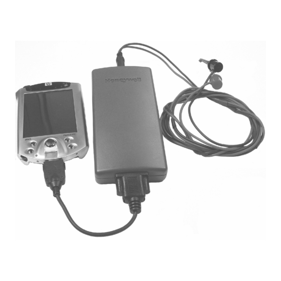
- Page 8 Figure 1 Components of the MC Toolkit........................1 Figure 2 MCT202 (rugged and intrinsically safe models)....................1 Figure 3 Honeywell ST 3000 Smart Transmitter - Analog mode...................4 Figure 4 Honeywell Analog Value Scaling ........................6 Figure 5 Honeywell DE Mode Value Scaling ........................8 Figure 6 Honeywell (HART) Transmitter Diagram ......................8...
-
Page 9: Introduction
Introduction Purpose/Scope This manual is intended to facilitate the use of the Honeywell MC Toolkit communications tool. It is assumed that the user is skilled in the use and maintenance of process transmitters in process control, or that he/she is under direct supervision of others with such skills. -
Page 10: Product Description
All versions of the PDA incorporate the Microsoft Pocket PC 2003 or 2005 Operating System. Honeywell software operates as an application package in the familiar MS Windows environment, and is virtually identical for all versions of the PDA. The MC Toolkit application or SDC 625 application can run simultaneously with other Pocket PC applications. -
Page 11: Procedural Considerations
HART Procedures, which are given in separate sections of this manual. Transmitter Type and Communication Mode The MC Toolkit can be used with various types of field transmitters, most of which can be operated in more than one mode. •... -
Page 12: Transmitter/Communications Characteristics
Transmitter/Communications Characteristics Transmitter/Communications Characteristics The characteristics of a typical Honeywell Smart Pressure Transmitter are summarized in Figure 3 through Figure 7, following. Honeywell Transmitter (Analog Mode) Analog-to-Digital Sensing As indicated by key number (1) in Figure 3, the sensor is a sealed assembly that typically includes three separate sensors: Differential Pressure (DP), Static Pressure (SP) and Temperature (Temp). - Page 13 Default conversion is to inches-H2O @39F.) The output of a Honeywell transmitter operating in the analog mode is a scaled value (0% - 100%) of current (4 mA to 20 mA), whose lower and upper limits correspond to the configured operating range (LRV-URV), respectively.
-
Page 14: Figure 4 Honeywell Analog Value Scaling
Figure 4 Honeywell Analog Value Scaling Digital (Communications Signal) Input/Output As indicated at the right of Figure 4, communications between the MC Toolkit and the Honeywell Smart Transmitter consist of digital pulse strings, with rapid transitions of current level between (approximately) 4 mA and 20 mA. - Page 15 PV (and other variables) and also for communications. CAUTION: Before connecting to a HART transmitter, ensure that the MC Toolkit is not set up for DE communications, whose current amplitude can "bump" process variables in either point-to- point mode or in multi-drop mode.
-
Page 16: Figure 5 Honeywell De Mode Value Scaling
It is recommended that the SDC 625 application software, based on DD-IDE/SDC-625 technology and "OPEN" tools standard, be used with non-Honeywell HART devices. The SDC 625 is based on HART Revision 5.0 and uses Device Descriptions stored in the Pocket PC to communicate to all universal, common and specific device commands. -
Page 17: Figure 7 Hart Point-Point And Multi-Drop Value Scaling
Introduction Figure 7 HART Point-point and Multi-Drop Value Scaling Release 3 34-ST-25-20 MC Toolkit User Manual 9/06... -
Page 18: General Procedures
Each of the following descriptions of features includes only the name of the feature and its functionality as it is used with the MC Toolkit. The details of each feature are provided in the HELP information that is included with the PDA. -
Page 19: Input Methods: Letter, Numbers, Symbols
(the box at bottom, on the left) or a numeric pad (on the right). The " " icon is a link to HELP; the @$ icon is a link to a table of symbols. Release 3 34-ST-25-20 MC Toolkit User Manual 9/06... - Page 20 Primer for MC Toolkit & SDC 625 Application Software Letter Recognizer Overview Empty Text Input Port Completing Entry In the Letter Recognizer method, characters are simply selected from a virtual QWERTY keyboard. As indicated at right, options include small keys or large keys. Short-cut options such as "gestures"...
-
Page 21: Mc Toolkit Application Software Display Conventions
In general, selecting a button in a display will call up the next-lower-level display, whose title is the same or similar to the label on the button. A menu tree for Honeywell DE Displays is given Figure 9, and a menu tree for HART display is given in Figure 10. - Page 22 MC Toolkit Application Software Display Conventions Menu Bar, Menu Selections, and HELP display File Exit To export an XML file, select File, Export. Closes the MC Toolkit application A popup message appears. Export Select the button. Enables export of database parameters in XML format, which can be used by other programs such as DocuMint.
-
Page 23: Data Entry And Display
2. Box with white background and with no arrow indicates Read/Write (R/W) text or numeric input field. Values previously stored in memory (of the transmitter or of the MC Toolkit) are displayed. The user can enter or modify values using an appropriate Input Method (e.g., Keyboard). -
Page 24: Sdc 625 Application Software Display Conventions
HART communication CD-ROM, are listed by Manufacturer and Product. For example, there is a folder listed as Honeywell. ST 3000 is listed as one product of four (with DD) under this folder. Other Manufacturers with DDs are listed also. If you are working with a HART Device and cannot find the DD in the list, please contact the Device Manufacturer. -
Page 25: Introduction
Using MC Toolkit Application Software with Honeywell DE Transmitters Introduction This section contains procedures for using the MC Toolkit application software to communicate with Honeywell DE Transmitters. For specific data relating to parameters involved in the procedures, refer to Reference Data... -
Page 26: Summary Of Operating Procedures
Summary of Operating Procedures To access displays for Honeywell DE Transmitters: • Start the MC Toolkit application; the CONNECT TO ... display will appear. (Refer to Figure 8 Start-up - MC Toolkit Application.) • Upload the database from the transmitter. (The QUICK MONITOR display will enable viewing of key parameters before taking the time for database uploading.) The DE MAIN MENU appears. - Page 27 Observe (Read): Configuration • • Critical Status Latching High/Low PV Values (STT 3000) • Write Protection • NAMUR • CJ Compensation Enter: • CJ Temp • Password (Write Protection) • New Password Release 3 34-ST-25-20 MC Toolkit User Manual 9/06...
-
Page 28: Procedural Considerations
(0%) and maximum (100%) level in a vessel. The Process Variable is carefully adjusted to stable minimum and maximum levels, and the LRV and URV values are then set by commands from the MC Toolkit. The DE Apply Values procedure is given in Table 7. Page 20 34-ST-25-20 MC Toolkit User Manual Release 3 9/06... -
Page 29: Table 2 De Upload Procedures
General Procedures Table 2 DE Upload Procedures DE Upload Procedures Select the DE Device button If the MC Toolkit is connected This Warning message to a DE Device, select the appears. button. Select the button; the Upload Note: wait cursor and progress bar This Warning appears only appear. -
Page 30: Table 3 De Main Menu Procedures
4 Byte or DE 6 Byte FS Direction (r) (Upscale or Downscale; selection is jumpered in the transmitter). Line Filter (r) Select: 50hz or 60hz. T/C Fault Detect (r/w): Select: Enabled or Disabled. Page 22 34-ST-25-20 MC Toolkit User Manual Release 3 9/06... - Page 31 (Refer to Transmitter User Manual). Flow EU Upper Value (r/w) Selection of standard Engineering Units for Flow Upper Value Flow EU Lower Value (r/w) Selection of standard Engineering Units for Flow Lower Value Release 3 34-ST-25-20 MC Toolkit User Manual 9/06...
- Page 32 Device Status display. Communication Status For status information, refer Input to the section on Sensor input in Engineering Messages and Units Diagnostic Codes. Output Loop output as percent of Span Page 24 34-ST-25-20 MC Toolkit User Manual Release 3 9/06...
-
Page 33: Table 4 Input Calibration (De Transmitters) - Correct Input (Zero), Lrv, Urv; Reset Corrects
Correct URV procedures in the same calibration session. The Correct LRV and Correct URV procedure should never be performed without first performing the Correct Input (Zero) procedure in the same calibration session. Release 3 34-ST-25-20 MC Toolkit User Manual 9/06... - Page 34 Input Calibration (De Transmitters) - Correct Input (Zero), LRV, URV; Reset Corrects Set-Up On Bench A typical bench set-up is shown at right. Connect the MC Toolkit as indicated, and establish communication with the transmitter. For these procedures, components in the...
- Page 35 This action sends the Correct Input (Zero) command to the transmitter, which adjusts the input calculation. Wait until this message When the transmitter has Select the button to appears. completed the Zero acknowledge. Correction, this message appears. Release 3 34-ST-25-20 MC Toolkit User Manual 9/06...
- Page 36 Correct URV Input at button. This message appears. temperature to the exact message appears. value of the URV entered in the DE CONFIGURE (STT 3000) display. Select the button to acknowledge Page 28 34-ST-25-20 MC Toolkit User Manual Release 3 9/06...
- Page 37 The timer will default appear briefly, indicating the ("characterization") operation is performed. values. It is intended for use only when excessive corrections render the transmitter inaccurate. Release 3 34-ST-25-20 MC Toolkit User Manual 9/06...
-
Page 38: Table 5 Output Calibration - Loop Test
To view the Monitor display, Example: Note: DE output (100 %), as navigate Back from the If the transmitter is in viewed on the MC Toolkit. LOOP TEST display and Analog mode, you can select the MONITOR observe the output on display. - Page 39 This message at right Select button only if appears if the user performs constant-current Output with an operation on the MC the MC Toolkit is intended. Caution: Toolkit that will terminate was selected as the connection to the Unintended above in the...
-
Page 40: Table 6 De Output Calibration - Trim Dac Current
0% (LRV), and 20 mA corresponds to 100% (URV). Call up In the DE MAIN Select the Trim DAC Curr. display MENU, select the button; this display appears. button. Calibration The CALIBRATION menu appears. Page 32 34-ST-25-20 MC Toolkit User Manual Release 3 9/06... - Page 41 NOTE: On the voltmeter, 4 mA corresponds to 1 volt. Using the MC Toolkit, adjust the loop current to the Zero Percent level (4 mA). If the current is low, tap the Increment button; if it is high, tap the Decrement button, and observe the change on the meter.
-
Page 42: Table 7 De Calibration - Apply Values
To update this value, select the button, and again select the Set LRV button in the CALIBRATION display. Page 34 34-ST-25-20 MC Toolkit User Manual Release 3 9/06... - Page 43 Input Value to the URV in the transmitter. If not, select NO and repeat this step. Verify The results of the Set LRV and Set settings URV actions can be verified by calling up the DE CONFIGURE display. Release 3 34-ST-25-20 MC Toolkit User Manual 9/06...
-
Page 44: Mc Toolkit Software With Honeywell Hart Transmitters
MC Toolkit Software with Honeywell HART Transmitters Introduction This section contains procedures for using the MC Toolkit application software to communicate with Honeywell and non-Honeywell Transmitters with HART communications protocol. In some cases, the Honeywell transmitters differ somewhat from non-Honeywell transmitters, separate procedures are provided as appropriate. -
Page 45: Figure 11 Menu Tree: Non-Honeywell Hart Displays
MC Toolkit Software with Honeywell HART Transmitters Figure 11 Menu Tree: non-Honeywell HART Displays Release 3 34-ST-25-20 MC Toolkit User Manual 9/06... -
Page 46: General Procedures
General Procedures To access displays for HART Transmitters: • Start the MC Toolkit application; the CONNECT TO ... display will appear. (Refer to Figure 8 Start-up - MC Toolkit Application). • Upload the database from the transmitter. (Refer to Table 9 in this section.) −... -
Page 47: Table 8 Hart Displays / Tasks Summary
MC Toolkit Software with Honeywell HART Transmitters Table 8 HART Displays / Tasks Summary Menu Item Task DEVICE INFO Enter: Observe (Read): • Device Type: Model • • Tag ID Device ID • Message • Manufacturer • Descriptor BASIC SETUP... -
Page 48: Procedural Considerations
• Device variable Procedural Considerations The details of procedures vary with device type. This section contains a set of procedures for Honeywell HART Transmitters, and separate set of procedures for non-Honeywell HART devices. Input Calibration Input calibration of transmitters should be done only when necessary, and should be done only under conditions that will ensure accuracy: •... -
Page 49: Output Calibration
(0%) and maximum (100%) level in a vessel. The PV is carefully adjusted to stable minimum and maximum levels, and the LRV and URV values are then set by commands from the MC Toolkit. For Honeywell HART devices, the procedure is given in Table 17, and for non-Honeywell devices consult the manufacturer’s User Manual. -
Page 50: Table 9 Hart Device Upload Procedure
Address drop-down box. - or - If you don't know the address of the device, select the POLL button. The MC toolkit will look for devices on all addresses (0-15), and will then list the addresses of all transmitters that respond. - Page 51 MC Toolkit Software with Honeywell HART Transmitters HART Device UPLOAD Procedure Initiate Select the button. When the Quick Monitor UPLOAD Upload display appears, use it to A wait cursor and a HART STT 25T progress bar appear while HART ST3000, STT25H,...
-
Page 52: Table 10 Honeywell Hart Main Menu Procedure
Procedural Considerations Table 10 Honeywell HART Main Menu Procedure Honeywell HART Main Menu Procedures Menu ST 3000 HART STT25H, STT25T styles: Note that the Note that the Alarm Local Meter functions are not function is not available Sensor available. Device... - Page 53 MC Toolkit Software with Honeywell HART Transmitters Honeywell HART Main Menu Procedures Basic Honeywell ST 3000 Honeywell STT25H Setup Transfer Function - Linear or Square Root CJT Units - Engineering Units for Cold (select) Junction Temperature (select) SV Units - Engineering Units for...
- Page 54 Corr. Input URV STT25H) (ST3000 and STT25H) Table 14 - Reset Corrects Table 17 - Apply Values (ST3000 and (STT25H) Table 15 - Loop Test Table 16 - D/A Trim Page 46 34-ST-25-20 MC Toolkit User Manual Release 3 9/06...
- Page 55 MC Toolkit Software with Honeywell HART Transmitters Honeywell HART Main Menu Procedures Local Local Meter refers to a For more information, refer Meter meter installed integrally in to the user manuals(s) for an ST 3000 transmitter, or to the transmitter and/or for the...
- Page 56 Match PV’s – When ON, the value of PV1 is assigned to the PV2. Line Filter - Select: 50 Hz/60 Hz. CJ Mode Comp - Select: Internal CJ or External CJ. Page 48 34-ST-25-20 MC Toolkit User Manual Release 3 9/06...
-
Page 57: Table 11 Honeywell Hart Diagnostics/Service Menu Procedures
MC Toolkit Software with Honeywell HART Transmitters Table 11 Honeywell HART Diagnostics/Service Menu Procedures Honeywell HART Diagnostics/Service Menu Procedures Menu Master Master Reset is the Reset functional equivalent of cycling power on the transmitter. No parameters are changed. Select the... - Page 58 Not enter the password, and then Write Protected. select the Send button. Change Password select the Start button, type in the new password, and then select the button. Send Page 50 34-ST-25-20 MC Toolkit User Manual Release 3 9/06...
-
Page 59: Table 12 Honeywell Hart Calibration - Zero Trim
MC Toolkit Software with Honeywell HART Transmitters Table 12 Honeywell HART Calibration - Zero Trim Honeywell HART Calibration Zero Trim Overview Requirements: Objective(s): • Input source, with accuracy of at Using a precision PV input source as a reference, least 0.04%... - Page 60 Select the button, and appears. settings. wait for this message: Select Zero Trim. The first of a series of Pop-Up messages appears. Select the button; the following message should appear. Page 52 34-ST-25-20 MC Toolkit User Manual Release 3 9/06...
-
Page 61: Table 13 Honeywell Hart Calibration - Lrv And Urv
MC Toolkit Software with Honeywell HART Transmitters Table 13 Honeywell HART Calibration - LRV and URV Correct Select Ensure that pressure input The LRV value is stored in Corr. Input LRV source is correct and is not the transmitter. varying. -
Page 62: Table 14 Honeywell Hart Calibration - Reset Corrects
Procedural Considerations Table 14 Honeywell HART Calibration - Reset corrects Reset Select the Reset Corrects Note: Corrects button. This function commands (ST3000 the transmitter to overwrite all user input STT25H) corrections with factory default ("characterization") values. It is intended for use only... -
Page 63: Table 15 Honeywell Hart Calibration - Loop Test
MC Toolkit Software with Honeywell HART Transmitters Table 15 Honeywell HART Calibration - Loop Test Honeywell HART Calibration - Loop Test Loop Test This function verifies the Select the desired current integrity of the physical level, then select components of analog... -
Page 64: Table 16 Honeywell Hart Calibration - D/A Trim
Procedural Considerations Table 16 Honeywell HART Calibration - D/A Trim Honeywell HART Calibration - D/A Trim D/A Trim This display appears. Select the Start D/A Trim NOTE: button. A popup message This procedure appears. calibrates the value of the analog output... - Page 65 MC Toolkit Software with Honeywell HART Transmitters Honeywell HART Calibration - D/A Trim Calibrate The 20 mA calibration In the example at right, 20 mA display appears. meter indication of 4.97 V Output is converted to 19.80 mA Again, observe the resulting...
-
Page 66: Table 17 Honeywell Hart Calibration - Apply Values
Procedural Considerations Table 17 Honeywell HART Calibration - Apply Values Honeywell HART Calibration - Apply Values • Overview Manually set Process Variable input to 0%, and apply this value to Set LRV (output) at 4 MA. Objectives • Manually set Process Variable input to 100%, and apply this value to set URV (output) at 20 mA. - Page 67 MC Toolkit Software with Honeywell HART Transmitters Honeywell HART Calibration - Apply Values Apply Select the OK button. The display at right Values: appears. The Current Applied Process Value field shows the value of the Process Value. A new sample of the input level is displayed each time the user selects the Read New Value button.
- Page 68 Procedural Considerations Honeywell HART Calibration - Apply Values (Write When the PV is stabilized, input value select the Set as New as URV.) Value button. This popup at right appears. Select the OK button to write the input value as the URV calibration value;...
-
Page 69: Using Sdc 625 Application Software With All Hart Transmitters And Devices
HART communications protocol. It is recommended that you use SDC 625 application software when communicating with non-Honeywell devices. After double-clicking on the SDC 625 icon, the following screen often appears. Choose “ignore”, it is an indicator that a configuration may have changed. - Page 70 Other devices, which require more configuration commands, will have a relatively complex main screen structure. The following table depicts the basic structure of a Device Setup menu for a Honeywell STT 250 temperature transmitter: Device Setup Submenu item...
- Page 71 2. The Backspace (top right on the keyboard) button can be used to remove blank characters if desired. 3. New values can be entered into the Textbox using the keyboard. After making a change (such as the Tag I.D.) the following screen will appear: Release 3 34-ST-25-20 MC Toolkit User Manual 9/06...
- Page 72 When you have fully configured the device or made the changes you need to make, you can exit the SDC625 program in the following way: Click on Device, and then Exit. Page 64 34-ST-25-20 MC Toolkit User Manual Release 3 9/06...
-
Page 73: Messages And Diagnostic Codes
Make sure ActiveSync is not running. If several programs are active, try closing one or more open programs. Error writing to Com Port! Stop the MC Toolkit application by doing File | Exit and restart the Error writing to Com Port! program. - Page 74 Modem network error Modem Transmitter Serial Error! No Response from the Transmitter Make sure that the MC Toolkit field connections are connected to the transmitter. Verify the transmitter is wired correctly and that it is powered. If connected to a DE transmitter, make sure the polarity of the cables connecting to the transmitter is correct.
- Page 75 Serial Port is not Available Make sure ActiveSync is not running. If Several programs are active, try closing one or more open programs. SetCommMask Error! Stop the MC Toolkit application by doing File | Exit and restart the SetCommState Error! program. SetCommTimeouts Error! Use the Pocket PC hardware reset.
-
Page 76: Table 19 De Messages
DE mode is digital only (no digital-to-analog conversion). allowed only in Analog Mode. The transmitter is in Output Mode. Are User tried to Exit MC Toolkit application while the DE Transmitter is still you sure you want to terminate the in Output Mode. -
Page 77: Table 20 Hart Messages
AP Sensor Types. applications. Table 20 HART Messages HART MESSAGES Bad Manufacturer Code MC Toolkit does not recognize the manufacturer code from the transmitter. Bad Status code from the transmitter MC Toolkit does not recognize the status code from the transmitter. - Page 78 Process applied to the non-primary variable is outside the operating limits of the field device. Parity Error! Bit 6 on first response code byte set. MC Toolkit detected a communications error in the HART message. Overrun Error! Bit 5 on first response code byte set Framing Error! Bit 4 on first response code byte set.
-
Page 79: Table 21 St 3000 Device Status Messages (De)
Meter Body Fault: The pressure input is greater than two times the URL of the transmitter Calibration correction values are Reset to Factory default Data for the DAC Temperature compensation is corrupted Release 3 34-ST-25-20 MC Toolkit User Manual 9/06... -
Page 80: Table 22 Stt Device Status Messages (De)
The transmitter is in the OUTPUT MODE and using a fixed output that is ""not from the process"" User correction active NON CRITICAL Suspect Input Backup thermocouple is active Input Status not Latched Custom Input Sensor Redundant T/C Mode Delta Temperature Mode 4 wire RTD mode Page 72 34-ST-25-20 MC Toolkit User Manual Release 3 9/06... -
Page 81: Table 23 St 3000 Device Status Messages (Hart)
Cold Start A reset or self test of the device has occurred, or power has been removed or applied. Configuration changed Device Malfunction - Field device has malfunctioned due to a hardware error or failure. Release 3 34-ST-25-20 MC Toolkit User Manual 9/06... -
Page 82: Table 24 Stt Device Status Messages (Hart)
NVM Calibration Failed NVM Configuration Failed XS Delta Sensor 1 failed Sensor 2 Failed XS Delta NON CRITICAL CJ Over Temp Input out of spec Output Saturated In Output Mode Page 74 34-ST-25-20 MC Toolkit User Manual Release 3 9/06... -
Page 83: Reference Data
Physical property such as pressure or temperature, applied to an input sensor PV Units Process Variable Standard scale of values of a PV, selected by the user for convenient Units display and interpretation. Release 3 34-ST-25-20 MC Toolkit User Manual 9/06... - Page 84 PV output goes to the Failsafe value and a Critical Status message is enunciated. If Off and the Delta Alarm value is exceeded, the PV output is not affected and a Non-Critical Status message is enunciated. 34-ST-25-20 MC Toolkit User Manual Release 3 9/06...
-
Page 85: Honeywell De Fields And Values
Sensor Type (ST only) Damping (STT only) 0.00 3.10 25.50 0.30 6.30 51.10 0.70 12.70 102.30 1.50 DE Configure Damping (ST only) 0.00 1.00 8.00 (continued) 0.16 2.00 16.0 0.32 4.00 32.0 0.48 Release 3 34-ST-25-20 MC Toolkit User Manual 9/06... - Page 86 @ 0C inH2O @ 39F mH2O 4C mmHg @ 0C g/cm² kg/cm² mmH2O @ 4C Custom Custom Units 8 characters Flow EU Upper Value Floating point Flow EU Lower Value Floating point 34-ST-25-20 MC Toolkit User Manual Release 3 9/06...
-
Page 87: Honeywell Hart Fields And Values
SV Units °C °R Kelvin °F Transfer Function Linear Square root Damping (ST only) 0.00 1.00 8.00 0.16 2.00 16.0 0.32 4.00 32.0 0.48 Damping (STT only) Floating point between 0 and 100 Release 3 34-ST-25-20 MC Toolkit User Manual 9/06... - Page 88 Break Detect (STT25H Enabled only) Disabled Latching Alarm Enabled Disabled XS Delta Sensor (STT only) Sensor Type (STT25H T/C-T JPT 100 only) T/C-E T/C-S PT100 T/C-J T/C-R PT200 T/C-K T/C-B Ohms T/C-N 34-ST-25-20 MC Toolkit User Manual Release 3 9/06...
- Page 89 3 Wire 4 Wire (continued) CJ Mode Compensation Internal CJ External CJ (STT25H) Compensation (STT25T) Write Protect (STT25H Write Protect Write protected Not write only) protected Password 4 chars New Password 4 chars Release 3 34-ST-25-20 MC Toolkit User Manual 9/06...
-
Page 90: Generic Hart Fields And Values
Temperature degF inH2O @ 39F torr Pressure inHg @ 32F Mbar ftH2O @ 68F g/cm² inH2O @ 60F mmH2O @ 68F kg/cm² mmHg @ 0C Pascals inH2O @ 4C mmH2O @ 4C 34-ST-25-20 MC Toolkit User Manual Release 3 9/06... - Page 91 ShTon/yd³ ug/l lb/ft³ degTwaddell ug/m³ g/ml Viscosity centistokes centipoises Electromagnetic Unit of Electric Potential Electrostatic Unit of Current Electromagnetic Unit of kOhms Resistance Energy newton-meter kilowatt hour Basic Setup Release 3 34-ST-25-20 MC Toolkit User Manual 9/06...
- Page 92 Non Critical Status (Field Primary Variable Loop Current Fixed Configuration Device Status) Out of Limits Changed More Status Non Primary Available Device Variable Out of Malfunction Cold Start Limits Loop Current Saturated 34-ST-25-20 MC Toolkit User Manual Release 3 9/06...
- Page 93 All PVs and Current Current Specific Number of Device 1 - 4 Monitor Variables to Query Dev. Var. 1 0 - 22 Dev. Var. 2 0 - 22 Dev. Var. 3 0 - 22 Release 3 34-ST-25-20 MC Toolkit User Manual 9/06...
- Page 94 Generic HART Fields and Values Dialog Field Value Dev. Var. 4 0 - 22 Dev. Var. 1 Floating point Dev. Var. 2 Floating point Dev. Var. 3 Floating point Dev. Var. 4 Floating point 34-ST-25-20 MC Toolkit User Manual Release 3 9/06...
-
Page 95: Table 29 Hart Universal Commands
Read Current and Four Dynamic Variables Write Polling Address Read Message Read Tag, Descriptor, Date Read PV Sensor information Read Output information Read final assembly number Write Message Write Tag, Descriptor, Date Release 3 34-ST-25-20 MC Toolkit User Manual 9/06... -
Page 96: Table 30 Hart Common Practice Commands
Read additional device status Read Dynamic Variable Assignments Write Dynamic Variable Assignments Write Transmitter Variable Units Read Burst mode configuration Write Burst Device Variables Write Burst mode command number Burst mode control 34-ST-25-20 MC Toolkit User Manual Release 3 9/06... -
Page 97: Xml Database (Samples)
XML Database (Samples) XML database files that can be exported from the MC Toolkit application to Documint (or other XML file utility) includes thirteen items. The specific content of each file depends on the type of field device from which it is exported, but the form of each item is the same for all devices. - Page 98 Field # Parameter Name Parameter Description Bus Type Protocol type Device Classification of device type: Honeywell DE (ST 3000, STT3000, Honeywell HART (STT25H), or generic (non- Honeywell) HART Tag ID User-defined identifier Serial Number Serial Number of device (assigned by Manufacturer) Manufacturer a.
-
Page 99: Mct101 Maintenance
Note the orientation of the battery in the compartment, and then remove it from the case. Noting orientation of the new battery and the terminals, insert the new battery into the case. Replace the cover and the retaining screw. Release 3 34-ST-25-20 MC Toolkit User Manual 9/06... -
Page 100: Mc Toolkit Software Installation/Maintenance
Note: The handheld computer needs to be connected to the MC Toolkit Modem for the MC Toolkit software to operate correctly. If the modem is not connected to the handheld computer, an error message will appear. Use the short interface cable provided for this purpose. -
Page 101: Mct202 Maintenance
WARNING !! Due to certification requirements, all hardware maintenance issues of the MCT202 necessitate that the unit must be returned to Honeywell for factory servicing. SD Card Replacement The SD card is not field replaceable. Call Customer Service numbers listed in the front of this document. - Page 102 CD ROM - Standard 51453286-501 Industrial Measurement and Control 34-ST-25-20 MC Toolkit User Manual Release 3 9/06 Honeywell International Inc. 16404 N. Black Canyon Highway Phoenix, AZ 85053...
-
Page 103: Mct202 Replacement Parts
Adapter for Docking Station 50017825-001 Docking Station, USB Cable 50017826-001 and Adapter Docking Station 50017827-001 Charger Battery Charger 50017828-001 USB I/F and Charger Cable kit 50018045-001 Cable Transmitter Connector Cable 50018046-001 Software CD ROM 51453286-501 Release 3 34-ST-25-20 MC Toolkit User Manual 9/06...