Table of Contents
Advertisement
Quick Links
- 1 Initial System Setup
- 2 Chapter 2 Installing the System
- 3 Connecting the System and Opening the Setup Utility
- 4 Setting Static CMC and Bmc Internal Ip Addresses
- 5 Replacing Hard Drives or Solid State Drives
- 6 Replacing a System I/O Controller (Sioc)
- 7 Replacing a Storage Controller Card Inside the Server Node
- Download this manual
See also:
Manual
Advertisement
Chapters
Table of Contents

Related Manuals for Cisco UCS S3260


Summary of Contents for Cisco UCS S3260
- Page 1 Cisco UCS S3260 Storage Server Chassis Installation and Service Guide Updated: October 08, 2018 Americas Headquarters Cisco Systems, Inc. 170 West Tasman Drive San Jose, CA 95134-1706 http://www.cisco.com Tel: 408 526-4000 800 553-NETS (6387) Fax: 408 527-0883...
- Page 2 OR ITS SUPPLIERS HAVE BEEN ADVISED OF THE POSSIBILITY OF SUCH DAMAGES. Cisco and the Cisco logo are trademarks or registered trademarks of Cisco and/or its affiliates in the U.S. and other countries. To view a list of Cisco trademarks, go to this URL: www.cisco.com/go/trademarks.
- Page 3 For information about the server nodes that are supported in this system, see the service note for your server node: Cisco UCS C3X60 M3 Server Node For Cisco UCS S3260 System Service Note • Cisco UCS C3X60 M4 Server Node For Cisco UCS S3260 System Service Note •...
- Page 4 Power supply status LED System unit identification button/LED Network link activity LED System status LED Pull-out asset tag (not visible under front bezel) Fan status LED 10 Internal-drive status LEDs Cisco UCS S3260 Storage Server Chassis Installation and Service Guide...
- Page 5 Firmware Utility port (one each SIOC) 10/100/1000 dedicated management port, RJ-45 Server node reset button (resets the chipset in the server node) connector (one each SIOC) Not used at this time Cisco UCS S3260 Storage Server Chassis Installation and Service Guide...
- Page 6 When you rack and cable the system, be sure to allow enough slack in the power cords and other cables so that the system can be pulled out on the slide rails far enough to allow clearance for opening the top covers. Cisco UCS S3260 Storage Server Chassis Installation and Service Guide...
- Page 7 (Optional) I/O expander, as shown (with M4 or M5 server node only) • (Optional) server node Server bay 2 • (Optional) server node (C3X60 M4 shown) • (Optional) disk expansion tray Cisco UCS S3260 Storage Server Chassis Installation and Service Guide...
- Page 8 For the locations of the replaceable components that are inside a server node, see the service note for your server node: Cisco UCS C3X60 M3 Server Node For Cisco UCS S3260 System Service Note • Cisco UCS C3X60 M4 Server Node For Cisco UCS S3260 System Service Note •...
- Page 9 This section shows the locations of the replaceable components that are inside the system I/O controller (SIOC), which is accessible from the rear of the chassis. The Version 02 SIOC (UCSC-S3260-SIOC) uses an integrated Cisco UCS VIC 1300 Series chip •...
- Page 10 When you connect to the system to manage the server nodes’ BMCs via the Cisco IMC interface, you physically connect to the ports on a SIOC. When you log into the Cisco IMC interface, you use a system management IP address. Each CMC and each BMC also has an IP address for internal communication.
- Page 11 Chapter 1 Overview Overview of Cisco UCS S3260 Architecture Figure 1-7 Management Architecture Cisco UCS S3260 Storage Server Chassis Installation and Service Guide...
- Page 12 Server 2 SSDs 1 and 2 can be controlled by a RAID controller card in server node 2. • Figure 1-9 Data Architecture in a Single-Server System With I/O Expander Cisco UCS S3260 Storage Server Chassis Installation and Service Guide 1-10...
- Page 13 The dual RAID controller used in M5 server nodes uses two supercap units. PCIe I/O The optional I/O expander provides two 8x Gen 3 PCIe expansion slots. • Version 03 SIOC only: one 8x Gen 3 PCIe expansion slot. • Cisco UCS S3260 Storage Server Chassis Installation and Service Guide 1-11...
- Page 14 Baseboard Cisco Integrated Management Controller (Cisco IMC) firmware. management Depending on your NIC mode settings, the Cisco IMC can be accessed through the SIOC dedicated management port or the SIOC QSFP ports. See also Management Architecture, page 1-8.
- Page 15 Use the statement number provided at the end of each warning to locate its translation in the translated safety warnings that accompanied this device. Statement 1071 Cisco UCS S3260 Storage Server Chassis Installation and Service Guide...
- Page 16 Invoice number of shipper (see the packing slip) • Model and serial number of the damaged unit • Description of damage • Effect of damage on the installation • Cisco UCS S3260 Storage Server Chassis Installation and Service Guide...
- Page 17 Ensure that the site power meets the power requirements listed in the System Specifications, • page A-1. You can use an uninterruptible power supply (UPS), if available, to protect against power failures. Cisco UCS S3260 Storage Server Chassis Installation and Service Guide...
- Page 18 • Equipment Requirements The slide rails supplied by Cisco Systems for this system do not require tools for installation if you install them in a rack that has square 0.38-inch (9.6 mm), round 0.28-inch (7.1 mm), or #12-24 UNC threaded holes.
- Page 19 Push down the rail release latch while you collapse the intermediate rail back into the rail assembly for safety. Figure 2-1 Removing the Inner Rail From the Assembly Rail release latch (close-up view) Inner rail release clip Cisco UCS S3260 Storage Server Chassis Installation and Service Guide...
- Page 20 The bottom of the slide rail assembly lines up with the intended bottom of the rack unit (RU). Push the front mounting pegs into the rack-post holes until you hear them click and lock. Cisco UCS S3260 Storage Server Chassis Installation and Service Guide...
- Page 21 Figure 2-3 Attaching Rail Assembly to the Rack Post Front mounting pegs, entering rack-post holes Rear peg spring-latch from the outside front Rear mounting pegs, entering rack post-holes from inside rear Cisco UCS S3260 Storage Server Chassis Installation and Service Guide...
- Page 22 Ensure that both inner rail release clips are pushed in before pushing the chassis into the rack. Push the Caution chassis into the rails slowly to avoid damaging the rails. Let go of the release clip buttons as the chassis begins to push in. Cisco UCS S3260 Storage Server Chassis Installation and Service Guide...
- Page 23 It is recommended that when you test pulling the chassis out from the rack for the first time that you place the mechanical lift under the chassis to avoid an accidental drop. Cisco UCS S3260 Storage Server Chassis Installation and Service Guide...
- Page 24 2-5). Slide the tab over the end of the rail until it clicks and locks. Open the hinged flap at the top of each plastic cable guide and route your cables through the cable guides Step 5 as desired. Cisco UCS S3260 Storage Server Chassis Installation and Service Guide 2-10...
- Page 25 CMA tab on arm closest to the system and end Rear of system of inner slide rail attached to system Cisco UCS S3260 Storage Server Chassis Installation and Service Guide 2-11...
- Page 26 180 degrees so that it points toward the rear of the system. Figure 2-6 Reversing the CMA CMA tab on end of width-adjustment slider Metal button for rotating Cisco UCS S3260 Storage Server Chassis Installation and Service Guide 2-12...
-
Page 27: Table Of Contents
Setting Static CMC and BMC Internal IP Addresses, page 2-18 Default Networking Settings The system is shipped with these settings: The default NIC mode is Cisco Card. The QSFP ports on either SIOC are used to access the Cisco • Integrated Management Controller (Cisco IMC) interface. -
Page 28: System Ip Addresses
SIOC 2 CMC IP—This is the internal address for the CMC in SIOC 2 (if installed). This address • can be assigned by your DHCP server, or you can set a static address by using the Cisco IMC interface. Server 1 BMC IP—This is the internal address for the board management controller (BMC) in server •... -
Page 29: Connecting The System And Opening The Setup Utility
Figure 1-1 on page 1-2). The system is in standby power mode when the LED is amber. Connect a KVM cable (Cisco PID N20-BKVM) to the KVM connector on either server node at the rear Step 2 of the system. -
Page 30: Setting Up The System Using The Cisco Imc Configuration Utility
NIC Mode—Set the NIC mode to select which ports to use for accessing the Cisco IMC management interface: Cisco Card (default)—The QSFP ports on the active SIOC are used to access Cisco IMC. You must • select a NIC redundancy setting. - Page 31 Optional: Set the port speed for the SIOC QSFP ports to either 40 Gbps or 4x10 Gbps. Step 12 “Adapter-1” refers to SIOC 1 and “Adapter-2” refers to SIOC 2, if present. If your system is running Cisco IMC 2.0(9) or later, the default setting is Auto, which Note automatically adjusts to your network installation.
-
Page 32: Setting Static Cmc And Bmc Internal Ip Addresses
If you left DHCP enabled, your DHCP server sets the CMC and BMC IP addresses and so these steps Note are not required. Perform the following procedure only if you are setting static IP addresses manually. Use a browser and the system management IP address to connect to the Cisco IMC management Step 1 interface. - Page 33 S3260 M5 server node. NIC Modes You can choose from the following NIC mode settings: Cisco Card (default)—The QSFP ports on the active SIOC are used to access Cisco IMC. You must • select a NIC redundancy setting.
- Page 34 When you upgrade the BIOS firmware, you must also upgrade the Cisco IMC firmware to the same Caution version or the system will not boot. Do not power on the system until the BIOS and Cisco IMC firmware match or the system will not boot.
- Page 35 This section describes the location and meaning of LEDs and buttons and includes the following topics: Front-Panel LEDs, page 3-2 • Rear-Panel LEDs and Buttons, page 3-4 • Internal Diagnostic LEDs, page 3-7 • Cisco UCS S3260 Storage Server Chassis Installation and Service Guide...
- Page 36 • off both server nodes, returning the LED to amber. System unit identification Off—The unit identification LED is not in use. • Blue, blinking—The unit identification LED is activated. • Cisco UCS S3260 Storage Server Chassis Installation and Service Guide...
- Page 37 (14 drive bays in each row). Figure 3-8 for an example. In this example, the red LED indicates that the failing drive is in the right half of the internal drive compartment, in row 3. Cisco UCS S3260 Storage Server Chassis Installation and Service Guide...
- Page 38 Version 03 SIOC. QSFP port link activity LED (on each port) 14 SIOC health LED (one each Version 03 SIOC only) Cisco UCS S3260 Storage Server Chassis Installation and Service Guide...
- Page 39 Amber—The server node is in standby power mode. Power is supplied only to • the Cisco IMC. It is safe to remove the server node from the chassis. Green—The server node is in main power mode. Power is supplied to all server •...
- Page 40 Table 3-3 Drive Expander Module Status LED LED Status P3V3 Present HDD Status None None None None Green Plug-in Good Amber No plug-in Amber Fail No plug-in Amber Plug-in Fail Cisco UCS S3260 Storage Server Chassis Installation and Service Guide...
- Page 41 HDD26 HDD40 HDD54 HDD13 HDD27 HDD41 HDD55 HDD14 HDD28 HDD42 HDD56 Drive fault (on each drive carrier) Fan module fault (on each fan module) Drive activity (on each drive carrier) Cisco UCS S3260 Storage Server Chassis Installation and Service Guide...
- Page 42 For the locations of the internal diagnostic LEDs inside the server node, see the service note for your server node: Cisco UCS C3X60 M3 Server Node For Cisco UCS S3260 System Service Note • Cisco UCS C3X60 M4 Server Node For Cisco UCS S3260 System Service Note •...
- Page 43 You can invoke a graceful shutdown or a hard shutdown of the entire S3260 system by using either the Cisco IMC interface or the system power button on the front panel. To completely remove power from the system, you must disconnect power cords from all power supplies.
- Page 44 Shutting Down an Individual Server Node You can invoke a graceful shutdown or a hard shutdown of a server node by using either the Cisco Integrated Management Controller (Cisco IMC) interface, or the power button that is on the face of the server node.
- Page 45 • Removing an I/O Expander From a Node (C3X60 M4 and S3260 M5 Server Nodes Only), page 3-13 • Removing the System I/O Controller (SIOC) Cover, page 3-13 • Cisco UCS S3260 Storage Server Chassis Installation and Service Guide 3-11...
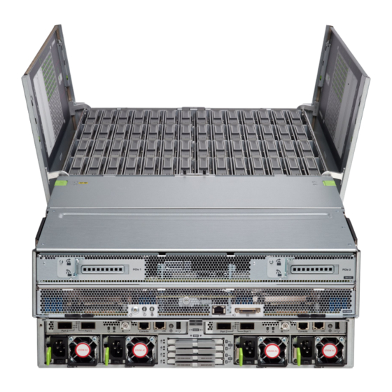
- Page 46 To secure the cover, hold both latch-buttons while you close the cover flat. Release the latch-buttons. Figure 3-4 Opening the Main Chassis Top Covers Latch-release buttons for left internal-drives Latch-release buttons for fan compartment compartment Latch-release buttons for right internal-drives compartment Cisco UCS S3260 Storage Server Chassis Installation and Service Guide 3-12...
- Page 47 Removing a Server Node Cover To remove a server node cover, see the service note for your server node: Cisco UCS C3X60 M3 Server Node For Cisco UCS S3260 System Service Note • Cisco UCS C3X60 M4 Server Node For Cisco UCS S3260 System Service Note •...
- Page 48 Removing the SIOC Cover (Version 03 SIOC, UCS-S3260-PCISIOC) SIOC cover, including ejector levers 3 Four securing screws on sides of cover (two each side) Two securing screws on top of cover Cisco UCS S3260 Storage Server Chassis Installation and Service Guide 3-14...
- Page 49 Replacing an NVMe SSD Inside the S3260 SIOC (Version 03 SIOC Only), page 3-42 • • Replacing an S3260 Chassis, page 3-47 • Service Headers on the Server Node Board, page 3-49 Cisco UCS S3260 Storage Server Chassis Installation and Service Guide 3-15...
-
Page 50: Replacing Hard Drives Or Solid State Drives
6 TB drives. Setting Up Booting in UEFI Mode in the BIOS Setup Utility Use a web browser and the management IP address of the system to log into the Cisco IMC GUI Step 1 management interface. - Page 51 Maintaining the System Installing or Replacing System Components Setting Up Booting in UEFI Mode in the Cisco IMC GUI Use a web browser and the management IP address of the system to log into the Cisco IMC GUI Step 1 management interface.
-
Page 52: Replacing Hdds Or Ssds In The Internal Drive Compartment
HDD49 HDD08 HDD22 HDD36 HDD50 HDD09 HDD23 HDD37 HDD51 HDD10 HDD24 HDD38 HDD52 HDD11 HDD25 HDD39 HDD53 HDD12 HDD26 HDD40 HDD54 HDD13 HDD27 HDD41 HDD55 HDD14 HDD28 HDD42 HDD56 Cisco UCS S3260 Storage Server Chassis Installation and Service Guide 3-18... - Page 53 Internal-Drive Status LED Example Internal-drive fault LEDs on right-front handle of system, 3 Front of system indicating faulty drive in right side of row 3 Fault LED on drive carrier Cisco UCS S3260 Storage Server Chassis Installation and Service Guide 3-19...
- Page 54 Cisco PID UCSC-C3X60-HD4TB (Toshiba model MG03SCA400) has been EOLed and should be Note replaced if any problems occur. This Cisco PID now uses a newer HGST model. SAS HDDs and SSDs are hot-swappable and can be replaced without removing power from the system.
-
Page 55: Replacing Hard Drives In The Optional Disk Expansion Tray
Lift the drive lever to the fully open position, then pull the drive straight up out of its bay. Spare drives are already installed in a carrier, so it is not necessary to remove the old drive from its carrier. Cisco UCS S3260 Storage Server Chassis Installation and Service Guide 3-21... - Page 56 Press the drive lever down flat until it clicks and locks. Figure 3-11 Drive Expander Module Drive Carrier Features Drive lever Drive fault LED Release button Drive activity LED Cisco UCS S3260 Storage Server Chassis Installation and Service Guide 3-22...
-
Page 57: Replacing Sas/Sata Solid State Drives In The Rear Panel Bays
Align the new drive with the empty bay (with the label facing up) and then push the drive in until it touches the board connector. Grasp and pinch the release latch toward the center while you push the drive fully into the bay, and then release the release latch. Cisco UCS S3260 Storage Server Chassis Installation and Service Guide 3-23... - Page 58 Solid State Drive Bay Features SSD release latch Solid state drive activity LED (each bay) Solid state drive fault LED (each bay) Blanking panel over lower bays (when not in use) Cisco UCS S3260 Storage Server Chassis Installation and Service Guide 3-24...
-
Page 59: Replacing Fan Modules
Close the fan compartment cover and then push the system back into the rack. Step 5 Figure 3-13 Fan Modules (Top View) Fan module fault LED Air flow direction arrow pointing toward rear of system Fan module release latches Cisco UCS S3260 Storage Server Chassis Installation and Service Guide 3-25... -
Page 60: Replacing A Server Node
Installing or Replacing System Components Replacing a Server Node The system can support one or two server nodes. Cisco IMC releases earlier than 2.0(13): If your S3260 system has only one server node, it must be • installed in bay 1. -
Page 61: Replacing A Disk Expansion Tray
Push the tray into the bay until it engages with the midplane connectors. Rotate both ejector levers toward the center until they lay flat and their latches lock into the rear of the tray. Cisco UCS S3260 Storage Server Chassis Installation and Service Guide 3-27... -
Page 62: Replacing A System I/O Controller (Sioc)
Note cards between Version 03 SIOCs in a system. A Version 01 SIOC from a Cisco C3160 system cannot be installed in a Cisco S3260 system. Note If you move a SIOC from one chassis to another, the SIOC’s CMC configuration is treated as Note incompatible and is automatically deleted. - Page 63 Power on the server node that you powered off earlier. Step 10 If you are using Cisco Card NIC mode, which uses the SIOC’s uplink interfaces to manage the Note system, you might need to configure the uplink’s port speed to either 4x10 Gbps or 40 Gbps to match your network installation.
- Page 64 The configuration in the active CMC is automatically synched with the standby CMC in the SIOC that you just installed. If you are using Cisco Card NIC mode, which uses the SIOC’s uplink interfaces to manage the Note system, you might need to configure the uplink’s port speed to either 4x10 Gbps or 40 Gbps to match your network installation.
- Page 65 Updating SIOC Adapter Firmware in a System With Dual SIOCs But Only One Server Node The recommended method for updating SIOC adapter firmware is to run the Cisco Host Upgrade Utility (HUU) on the server node that is associated with the SIOC. However, if a system has only one server node and two SIOCs, this method does not work to upgrade firmware on the SIOC that is not associated with a server node (SIOC 1 is associated with a server node in bay 1;...
- Page 66 Installing or Replacing System Components The adapter and host reset. The activated firmware becomes the running version. Using the Cisco IMC PMCLI Interface to Update SIOC Adapter Firmware Update and activate the adapter firmware by using the following commands: Step 1 Server# scope chassis Server/chassis# update-adapter-fw <protocol>...
-
Page 67: Replacing A Power Supply
Connect the power cord to the new power supply. If you powered off the system, press and hold the system Power button for four seconds to return the system to main power mode. Cisco UCS S3260 Storage Server Chassis Installation and Service Guide 3-33... - Page 68 Turn off the DC power source from your facility’s circuit breaker to avoid electric shock hazard. Step 1 The required DC input cable is Cisco part CAB-48DC-40A-8AWG. This 3-meter cable has a 3-pin Note connector on one end that is keyed to the DC input socket on the power supply, as shown in Figure 3-17.
- Page 69 Connect the CAB-48DC-40A-8AWG keyed cable connector to the new power supply. If you powered off the system, press and hold the system Power button for four seconds to return the system to main power mode. Cisco UCS S3260 Storage Server Chassis Installation and Service Guide 3-35...
-
Page 70: Replacing Dimms Inside A Server Node
Replacing DIMMs Inside a Server Node To replace DIMMs inside a server node, see the service note for your server node: Cisco UCS C3X60 M3 Server Node For Cisco UCS S3260 System Service Note • Cisco UCS C3X60 M4 Server Node For Cisco UCS S3260 System Service Note •... -
Page 71: Installing A Trusted Platform Module (Tpm) Inside The Server Node
Replacing a Storage Controller Card Inside the I/O Expander (C3X60 M4 Server Nodes Only) To replace a storage controller card inside an optional I/O expander, see the service note for the Cisco UCS C3000 M4 server node: Cisco UCS C3000 M4 Server Node For Cisco UCS C3260 System Service Note •... -
Page 72: Replacing An Rtc Battery Inside The S3260 Sioc
Replacing an RTC Battery Inside the S3260 SIOC The real-time clock (RTC) battery retains settings when the SIOC is disconnected from power. The battery type in the SIOC is CR1632. Cisco supports the industry-standard CR1632 battery, which can be purchased from most electronic stores. - Page 73 Battery socket on version 02 SIOC board, with CR1632 battery Figure 3-19 RTC Battery Location Inside the Version 03 S3260 SIOC (UCS-S3260-PCISIOC) Battery socket on Version 03 SIOC board, with CR1632 battery Cisco UCS S3260 Storage Server Chassis Installation and Service Guide 3-39...
-
Page 74: Replacing A Pcie Adapter Card Inside The S3260 Sioc (Version 03 Sioc Only)
Close the two levers on the SIOC to fully engage the SIOC connector with its backplane. Tighten the thumbscrew on the SIOC levers. Power on the server node that you powered off earlier. Step 8 Cisco UCS S3260 Storage Server Chassis Installation and Service Guide 3-40... - Page 75 Removable SIOC side panel (three screws on underside) Cisco VIC Cards Supported in Version 03 SIOC (UCSC-S3260-PCISIOC) At this time, the following Cisco Virtual Interface Card (VIC) is supported in the Version 03 SIOC: Cisco UCS VIC 1455 (UCSC-PCIE-C25Q-04) •...
-
Page 76: Replacing An Nvme Ssd Inside The S3260 Sioc (Version 03 Sioc Only)
1, you cannot populate an NVMe SSD in the SERVER 1 NVME slot in either SIOC. See Figure 3-21and Figure 3-22 for illustrations of the system connectivity and labeling. Figure 3-21 NVMe SSD Connectivity in Version 03 SIOC (UCS-S3260-PCISIOC) Cisco UCS S3260 Storage Server Chassis Installation and Service Guide 3-42... - Page 77 Loosen the two captive thumbscrews that secure the sled to the SIOC floor and then pull the sled so that the connectors on any installed SSDs disengage from the two sockets on the SIOC board. Figure 3-22 NVMe SSDs in Version 03 SIOC (UCS-S3260-PCISIOC) Cisco UCS S3260 Storage Server Chassis Installation and Service Guide 3-43...
- Page 78 Populate this slot only when you have a server node in lower server bay 2. SERVER 1 NVME Populate this slot only when you have a server node in upper server bay 1. Cisco UCS S3260 Storage Server Chassis Installation and Service Guide 3-44...
- Page 79 Push the SIOC into its bay until it stops against the internal midplane. Close the two levers on the SIOC to fully engage the SIOC connector with its backplane. Cisco UCS S3260 Storage Server Chassis Installation and Service Guide 3-45...
- Page 80 Chapter 3 Maintaining the System Installing or Replacing System Components Tighten the thumbscrew on the SIOC levers. Power on the server node that you powered off earlier. Step 9 Cisco UCS S3260 Storage Server Chassis Installation and Service Guide 3-46...
-
Page 81: Replacing An S3260 Chassis
Refer to the Cisco UCS Integrated Management Controller CLI Configuration Guide for S3260 Storage Servers. See the chapter, Server Utilities and the section, Exporting and Importing the Cisco IMC and BMC Configuration. Perform a graceful shutdown of all server nodes. - Page 82 Note must perform initial setup as you would for a new system. Power on, connect cables to the system, and log in to the Cisco IMC Configuration Utility as described Step 16 Connecting the System and Opening the Setup Utility, page 2-15.
-
Page 83: Service Headers On The Server Node Board
The server node includes headers that you can jumper for certain service functions. For information about the service headers, see the service note for your server node: Cisco UCS C3X60 M3 Server Node For Cisco UCS S3260 System Service Note •... - Page 84 Chapter 3 Maintaining the System Service Headers on the Server Node Board Cisco UCS S3260 Storage Server Chassis Installation and Service Guide 3-50...
- Page 85 A P P E N D I X System Specifications This appendix lists the technical specifications for the Cisco UCS S3260 Storage Server and includes the following sections: System Physical Specifications, page A-1 • System Environmental Specifications, page A-2 •...
- Page 86 0 m to 3048 m (0 ft to 10,000 ft) Derated 1ºC for each 305 m Altitude, nonoperating 0 m to 12,192 m (0 ft to 40,000 ft) Acoustic noise, operating LWAd 5.4 Bel LpAm 38 dBA Cisco UCS S3260 Storage Server Chassis Installation and Service Guide OL-22326-01...
- Page 87 • 1050 W DC Power Supply (UCSC-PSUV2-1050DC), page A-4 • You can get more specific power information for your exact server configuration by using the Cisco UCS Power Calculator: http://ucspowercalc.cisco.com Do not mix power supply types in the server. Both power supplies must be identical.
- Page 88 Appendix A System Specifications Power Specifications 1050 W DC Power Supply (UCSC-PSUV2-1050DC) Table A-4 lists the specifications for each 1050 W DC power supply (Cisco part number UCSC-PSUV2-1050DC). Table A-4 Power Supply Specifications Description Specification DC input voltage range Nominal range: –48 to –60 VDC nominal (Range: –40 to –72 VDC)
- Page 89 N5000 power cable, 250 VAC 10 A, Australia CAB-9K10A-EU N5000 power cable, 250 VAC 10 A, Europe CAB-9K10A-IT N5000 power cable, 250 VAC 10 A, Italy CAB-9K10A-SW N5000 power cable, 250 VAC 10 A, Switzerland Cisco UCS S3260 Storage Server Chassis Installation and Service Guide...
- Page 90 N5000 power cable, 250 VAC 10 A, Argentina CAB-250V-10A-CN N5000 power cable, 250 VAC 10 A, China CAB-250V-10A-ID N5000 power cable, 250 VAC 10A, India CAB-250V-10A-IS N5000 power cable, 250 VAC 10 A, Israel Cisco UCS S3260 Storage Server Chassis Installation and Service Guide...
- Page 91 For information about the storage controllers that are supported in your server node, see the service note for your server node: Cisco UCS C3X60 M3 Server Node For Cisco UCS S3260 System Service Note • Cisco UCS C3X60 M4 Server Node For Cisco UCS S3260 System Service Note •...
- Page 92 Appendix C Storage Controller Considerations Cisco UCS S3260 Storage Server Chassis Installation and Service Guide OL-27640-01...
- Page 93 Cisco UCS manager integration requires Cisco UCS Manager 3.1(2) or later. You can integrate a system that has either M3 or M4 server nodes, but the system must be using Cisco IMC 2.0(13) or later firmware. The Cisco UCS integration instructions are in the GUI and CLI integration guides found here: Cisco UCS S3260 Server Integration with UCS Manager Guides Refer to the guide that is for the version of Cisco UCS Manager that you are using.
- Page 94 Appendix D Installation for Cisco UCS Manager Integration Cisco UCS S3260 Storage Server Chassis Installation and Service Guide...
- Page 95 Installing a Second Server Node or SIOC to the S3260 System With M5 Server Node, page E-11 • Migrating From Version 02 SIOC to Version 03 SIOC, page E-14 • Older Migration and Upgrade Procedures, page E-18 • Cisco UCS S3260 Storage Server Chassis Installation and Service Guide...
-
Page 96: Differences Between Cisco Ucs C3160 And S3260 Systems
Differences Between Cisco UCS C3160 and S3260 Systems Differences Between Cisco UCS C3160 and S3260 Systems Table E-1 lists the differences between Cisco UCS C3160 and Cisco UCS S3260 systems. Table E-1 Differences Between Cisco UCS C3160 and Cisco UCS S3260 Systems... -
Page 97: Upgrading From S3260 With One M4 Server Node To S3260 With One M5 Server Node
Upgrading From S3260 With One M4 Server Node to S3260 With One M5 Server Node This procedure upgrades a Cisco UCS S3260 system that is using one C3X60 M4 server node to a Cisco UCS S3260 system that uses one S3260 M5 server node. - Page 98 You must upgrade your system firmware to the required minimum level before you upgrade to M5 server Caution nodes. Older firmware versions cannot recognize the new CPUs and this results in a non-bootable server. Make sure that Server SIOC Connectivity is set to Single Server Single SIOC in the Cisco IMC before Note starting this procedure.
- Page 99 Step 8 Check the firmware versions for the CMC, BMC, BIOS, SAS expander, and SIOC adapter. Connect a KVM cable (Cisco PID N20-BKVM) to the KVM connector on the server node at the rear of the Step 9 system. Connect a USB keyboard and a VGA monitor to the KVM cable.
- Page 100 Cisco IMC interface, as described in Setting Static CMC and BMC Internal IP Addresses, page 2-18. Use the Cisco IMC (GUI or CLI) to define hard drive zoning, which maps the hard drives to individual Step 16 server nodes: Using the Cisco IMC GUI: •...
-
Page 101: Upgrading From S3260 With Two M4 Server Nodes To S3260 With Two M5 Server Nodes
Upgrading From S3260 With Two M4 Server Nodes to S3260 With Two M5 Server Nodes This procedure upgrades a Cisco UCS S3260 system that is using two C3X60 M4 server nodes to a Cisco UCS S3260 system that uses two S3260 M5 server nodes. - Page 102 Step 6 Check the firmware versions for the CMC, BMC, BIOS, SAS expander, and both SIOC adapters. Connect a KVM cable (Cisco PID N20-BKVM) to the KVM connector on either server node at the rear Step 7 of the system. Connect a USB keyboard and a VGA monitor to the KVM cable.
- Page 103 Setting Static CMC and BMC Internal IP Addresses, page 2-18. Use the Cisco IMC (GUI or CLI) to define hard drive zoning, which maps the hard drives to individual Step 15 server nodes. Use either the Cisco IMC GUI or the Cisco IMC CLI: Using the Cisco IMC GUI: •...
- Page 104 Appendix E Upgrading to Cisco UCS S3260 System With S3260 M5 Server Nodes Upgrading From S3260 With Two M4 Server Nodes to S3260 With Two M5 Server Nodes Server# scope chassis Server /chassis # scope dynamic-storage svbu-huu-sanity-col2-1-vcmc /chassis/dynamic-storage # assign-drive server2 27 Are you sure you want to assign drives 27 to server2 Enter 'yes' to confirm ->...
-
Page 105: Installing A Second Server Node Or Sioc To The S3260 System With M5 Server Node
If the S3260 system has been configured to use your DHCP server, allow it to assign the CMC IP • address to the new SIOC. If you are not using a DHCP server, use the Cisco IMC interface (CLI or GUI) to manually assign • a CMC IP address for the new SIOC, as described in... - Page 106 Rotate both ejector levers toward the center until they lay flat and their latches lock into the rear of the server node. Verify that the server node is manageable from the S3260 Cisco IMC CLI or GUI. If the new server is Step 3 not displayed in the CLI or GUI, then you must reset the server to factory defaults.
- Page 107 Upgrading to Cisco UCS S3260 System With S3260 M5 Server Nodes Installing a Second Server Node or SIOC to the S3260 System With M5 Server Node If you are not using a DHCP server, use the Cisco IMC interface (CLI or GUI) to manually assign •...
-
Page 108: Migrating From Version 02 Sioc To Version 03 Sioc
Configure IP addresses and network settings. Perform drive zoning for hard drives. Full Procedure Ensure that the entire Cisco S3260 system with M5 server node is running Cisco IMC 3.1(3a) firmware Step 1 before you begin the upgrade. If the system is running an earlier version, download and run the S3260 Host Upgrade Utility (HUU) for release 3.1(3a):... - Page 109 Step 6 Check the firmware versions for the CMC, BMC, BIOS, SAS expander, and SIOC adapter. Connect a KVM cable (Cisco PID N20-BKVM) to the KVM connector on the server node at the rear of Step 7 the system. Connect a USB keyboard and a VGA monitor to the KVM cable.
- Page 110 Setting Static CMC and BMC Internal IP Addresses, page 2-18. Use the Cisco IMC (GUI or CLI) to define drive zoning, which maps the NVMe SSD drives in the Step 14 Version 03 SIOC(s) to individual server nodes: An NVMe SSD in the SIOC slot that is labeled SERVER 1 NVME is supported only by a server Note node in upper server bay 1.
- Page 111 Installing a Second Server Node or SIOC to the S3260 System With M5 Server Node Using the Cisco IMC GUI: • Use the IP address of the CMC in either SIOC to log in to the Cisco IMC management software. Navigate to the following tab: Chassis > Inventory > Dynamic Storage > Zoning Select the drives and then assign them to Server1 or Server2.
-
Page 112: Older Migration And Upgrade Procedures
Upgrading From S3260 With One M3 Server Node to S3260 With One M4 Server Node This procedure upgrades a Cisco UCS S3260 system that is using one C3X60 M3 server node to a Cisco UCS S3260 system that uses one C3X60 M4 server node. - Page 113 Caution nodes. Older firmware versions cannot recognize the new CPUs and this results in a non-bootable server. Ensure that the entire Cisco S3260 system with M3 server node is running Cisco IMC 2.0(7) or 2.0(9) Step 1 firmware before you begin the upgrade.
- Page 114 Reconnect power cables to the system. Wait for approximately five minutes to allow the system to boot Step 8 Connect a KVM cable (Cisco PID N20-BKVM) to the KVM connector on the server node at the rear of Step 9...
- Page 115 Cisco IMC interface, as described in Setting Static CMC and BMC Internal IP Addresses, page 2-18. Use the Cisco IMC (GUI or CLI) to define hard drive zoning, which maps the hard drives to individual Step 17 server nodes: Using the Cisco IMC GUI: •...
- Page 116 Upgrading From S3260 With Two M3 Server Nodes to S3260 With Two M4 Server Nodes This procedure upgrades a Cisco UCS S3260 system that is using two C3X60 M3 server nodes to a Cisco UCS S3260 system that uses two C3X60 M4 server nodes.
- Page 117 Caution nodes. Older firmware versions cannot recognize the new CPUs and this results in a non-bootable server. Ensure that the entire Cisco S3260 system with M3 server nodes is running Cisco IMC 2.0(7) or 2.0(9) Step 1 firmware before you begin the upgrade.
- Page 118 Reconnect power cables to the system. Wait for approximately five minutes to let the server nodes boot Step 6 to standby power during the first bootup. Connect a KVM cable (Cisco PID N20-BKVM) to the KVM connector on either server node at the rear Step 7 of the system (see Figure E-3).
- Page 119 Setting Static CMC and BMC Internal IP Addresses, page 2-18. Use the Cisco IMC (GUI or CLI) to define hard drive zoning, which maps the hard drives to individual Step 15 server nodes. Use either the Cisco IMC GUI or the Cisco IMC CLI: Using the Cisco IMC GUI: •...
- Page 120 See System IP Addresses, page 2-14 for more information. The latest Host Upgrade Utility package for Cisco IMC 2.0(8) or 2.0(9) firmware. This is used to • update the entire Cisco C3160 system to the prerequisite firmware. The Host Upgrade Utility package for Cisco IMC 2.0(13) or later firmware. This is used to upgrade •...
- Page 121 Older Migration and Upgrade Procedures Migrating From C3160 With One M3 Server Node to S3260 With One M4 Server Node The entire Cisco C3160 system must be running Cisco IMC 2.0(8) or 2.0(9) before you can begin the Step 1 migration.
- Page 122 Setting Static CMC and BMC Internal IP Addresses, page 2-18. Optional—At this point, you can install a second server node and a second SIOC to the Cisco S3260 Step 15 chassis. See Installing a Second Server Node or SIOC to the S3260 System With M4 Server Nodes, page E-28.
- Page 123 If the S3260 system has been configured to use your DHCP server, allow it to assign the CMC IP • address to the new SIOC. If you are not using a DHCP server, use the Cisco IMC interface (CLI or GUI) to manually assign • a CMC IP address for the new SIOC, as described in...
- Page 124 Rotate both ejector levers toward the center until they lay flat and their latches lock into the rear of the server node. Verify that the server node is manageable from the S3260 Cisco IMC CLI or GUI. If the new server is Step 3 not displayed in the CLI or GUI, then you must reset the server to factory defaults.