
Related Manuals for microHAM STATION MASTER


Summary of Contents for microHAM STATION MASTER
- Page 1 © 2016 All rights reserved STATION MASTER microHAM fax: +421 2 4594 5100 e-mail: support@microham.com homepage: www.microham.com Version 2.1 10 June 2016...
-
Page 2: Table Of Contents
Front Panel ......................... 5 Rear Panel .......................... 6 4. BLOCK DIAGRAM ........................8 5. INSTALLATION .......................... 9 Preparing Station Master for Use..................9 Installing microHAM USB Device Router ................12 Configuring microHAM USB Device Router ..............13 Station Master Status ......................13 Initial Setup ........................ -
Page 3: Features And Functions
Receive only antenna support • Optical isolation from computer • PS/2 keyboard or keypad with dual control of Station Master and microHAM “keyer” • Integrated chokes and filters for maximum RFI resistance • Metal/Aluminum case, powder coated and silk screened •... -
Page 4: Important Warnings
Automatic band switching for BCD controlled amplifiers (Yaesu VL-1000, FL-7000) • Support for QSK Power Amplifiers • 2 - IMPORTANT WARNINGS ALWAYS check the polarity of the 13.8 V power supply. If your radio includes upgradeable firmware DO NOT perform any upgrade through Station Master. -
Page 5: Panel Description
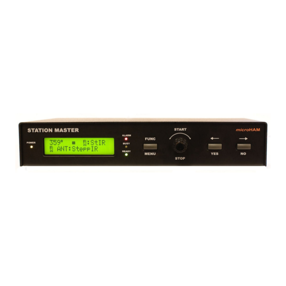
© 2016 All rights reserved 3 - PANEL DESCRIPTION Front Panel 1. POWER LED lights when +13.8V is applied (power switch on). 2. ALARM LED lights when “ALARM” condition happens, transmission is allowed. LED flashes when “ALARM” condition happens, transmission is inhibited. -
Page 6: Rear Panel
MiniDIN6 for PS/2 keyboard or PS/2 keypad. 8. INHIBIT Power inhibit output for Yaesu transceivers. RCA jack TIP - Signal SHELL - GND 9. CAT 4 pole 3.5mm phone jack for transceiver control. Compatible with microHAM “CAT” cables. 10. GND Terminal for connection to station ground. - Page 7 DB25 female for antenna switch, BPF and/or sequencer connection See Appendix – Connectors for details 15. PTTIN PTT input for connection with PTT output from transceiver or PATTT from microHAM “keyer” Active when grounded RCA jack: Tip – signal, Shell - ground...
-
Page 8: Block Diagram
© 2016 All rights reserved 4 – Block Diagram Station Master block diagram... -
Page 9: Installation
Be sure to observe the proper polarity. Do not turn on Station Master at this time. Locate the USB cable but DO NOT connect it to the USB jack of Station Master at this time. Connecting Station Master with micro HAM micro KEYER, DigiKEYER or CW KEYER: 1. - Page 10 Important: Connecting INHIBIT is best way to prevent hot switching. 5. Remove the top cover from Station Master and set the CAT jumpers as shown in the following chart. The CAT interface jumpers must be configured to select the proper signal level for your transceiver.
- Page 11 © 2016 All rights reserved 6. Remove the top cover from Station Master and set the CAT jumpers as shown in the following chart. The CAT interface jumpers must be configured to select the proper signal level for your transceiver.
-
Page 12: Installing Microham Usb Device Router
Router elsewhere, please accept the default location. When the Router installation is completed, click "Finish" to launch Router for the first time. Plug in the USB cable, turn ON Station Master and proceed to configuring Router for your station and software. -
Page 13: Configuring Microham Usb Device Router
Station Master. This happens when the USB cable is unplugged or the USB driver is not correctly installed. Initial Setup Router must be used to configure Station Master for proper operation. The device configuration tabs (in the red rectangle) are used to setup each part of the Station Master. -
Page 14: Creating And Using Virtual Serial Ports
Router provides a set of virtual serial ports which allow Windows applications (logging or control software) to work with Station Master just as they would work with "real" (hardware) serial ports. In order to use these virtual Ports, you must first create the ports and then assign a port to each function you wish to use (CAT radio control, Rotator, etc.). -
Page 15: Microham Device Router
Programs menu. Exit: Clicking on this item will terminate Router. NOTE: when Router is terminated the virtual ports will be closed and application software will be unable to communicate with Station Master and the radio. -
Page 16: Menu: Preset
Each preset contains the settings for all devices connected to, and controlled by, Router. For example, if Router controls a Station Master, microKEYER II, and a USB Interface II, each preset remembers the settings for ALL devices including the assignment of COM ports and the contents of all sub-tabs except the FSK and CW Messages tabs. -
Page 17: Menu: Device
Station Master's EEPROM. If Station Master is operated without connection to the computer it will use the settings stored in EEPROM. If Station Master is connected to a computer running Router, the power- up settings will be overridden by the Router settings but the default settings are retained in EEPROM. -
Page 18: Menu: Virtual Port
© 2016 All rights reserved NOTE: When upgrading Router, the upgrade will include the latest firmware for Station Master. If the firmware is newer than the currently installed firmware, Router will automatically ask for permission to update the installed firmware the first time it connects to Station Master. -
Page 19: Menu: Help
About: Shows the Router's internal version number. DEVICE CONFIGURATION TABS There are six (6) tabs for configuring Station Master. Each tab controls part of Station Master's functions. Except for Antenna Switching & PTT Sequencer and Rotator, any change is applied immediately. -
Page 20: Ports Tab
Router then in the application. IMPORTANT: Correct port assignment is critical for proper operation with application software. Station Master has six channels – each channel provides an indication of the settings applied by the application and current state (e.g., or or off): CAT (uses RxD and TxD) ●... -
Page 21: Nd Cat
NOTE: Do not connect a PW-1 or other Icom compatible peripheral in parallel with the transceiver when using Station Master. Instead configure and use the local PA Port. The PA port will provide an isolated CI-V bus and avoid the documented problems with collisions on the bus. - Page 22 USB transmits data in frames with a delay between frames. Router indicates frame boundaries with three dots (...) when a packet is split between frames. IMPORTANT: If Station Master is to operate in stand alone mode (without Router), the settings must be saved as power-up defaults using “Device | Store as Power-Up Settings.”...
-
Page 23: Ports: Rotator & 2 Ports: Auxiliary
The Auxiliary Port allows an application program to control an auxiliary device attached to the SERIAL port on the rear panel of Station Master rear panel. Only serial in (RxD) and serial out (TxD) are supported. To enable the Auxiliary port, set the "Serial port function" at the bottom of the Antenna Switching & PTT Sequencer Antenna sub-tab to Auxiliary port. -
Page 24: Ports: Control
The Control Protocol Monitor functions the same as the Rotor Port Monitors. iLINK couple When Station Master is used with a microHAM keyer and the two devices are connected using the iLINK port. The iLINK couple box specifies to which keyer is Station Master coupled. -
Page 25: Antenna Switching & Ptt Sequencer Tab
NOTE: Loading a file only fills the sub-tabs and DOES NOT automatically store those settings to the Station Master. When you wish to configure Station Master from a file, you must load the file into Router and then Store the settings to Station Master. - Page 26 The INT position connects the common terminal to the SRC/SNK jumper. In the SRC position, the common terminal is connected to Station Master's power supply (+13 Volts); in this configuration the outputs are voltage sourcing. In the SNK position, the common terminal is connected to Station Master's ground; these outputs are sinking (switch to ground).
- Page 27 © 2016 All rights reserved Before Station Master most band decoders simply accepted band data – either BCD data or an analog voltage representing the entire amateur band. Even those decoders that obtain frequency information from the radio's control (CAT) port simply determine the appropriate amateur band and selected one output for the entire band.
-
Page 28: Antenna Switching & Ptt Sequencer: Antennas
Flag for any antenna which is “receive only.” SM will not allow transmitting into this antenna. SteppIR: This flag indicates that this antenna is a SteppIR AND is controlled from the Station Master serial port using the SteppIR native protocol. Do not check this box if the antenna is controlled using Icom CI-V protocol . - Page 29 TX. Serial port functions Station Master contains one RS232 port that can be used for for control of a SteppIR antenna, provide support for Icom compatible accessories, or be used as a general purpose serial port.
- Page 30 Not connect to any other pin; doing so will cause the SteppIR Controller to operate improperly. The SteppIR controller must be switched to the General frequency mode and baud rate for serial port in Station Master must be same as the SteppIR controller.
-
Page 31: Antenna Switching & Ptt Sequencer: Virtual Rotators
VIRTUAL ROTATORS A unique feature of Station Master is the ability to combine several fixed antennas in a “virtual rotator.” This allows automatic direction selection under application control just as if the group of fixed antennas was single antenna turned by a conventional rotator. -
Page 32: Antenna Switching & Ptt Sequencer: Antenna Groups
Short abbreviation up to 5 characters long used for compressed displays. RX only: Flag for any antenna which is “receive only.” Station Master will not allow transmitting into this antenna. If all antennas of a virtual rotator are set as RX only, the entire virtual rotator is automatically RX only. - Page 33 © 2016 All rights reserved Each line (blue background) within a group represents one antenna. The number of antennas in a group is not limited. New antennas can be added to a group by clicking the Add button. Antennas can be removed from a group by selecting the antenna (orange background) and clicking Remove.
-
Page 34: Antenna Switching & Ptt Sequencer: Pa & Sequencer
Read this section carefully. The settings on this tab are important to prevent hot switching. Power Amplifier: If you are using a power amplifier, is necessary to control it from the Station Master PA port and not directly from the transceiver. Pin assignments for the signals at the PA connector are in Appendix A. - Page 35 The first line, labeled Source PTT, shows the behavior of the PTT control signal. Source PTT represents any PTT that can indicate to Station Master that the transceiver is being, or has been switched into transmit and Station Master should take the appropriate action.
- Page 36 ● and/or longest sequencer lead delay. make the PTT lead time in the KEYER equal to the INH time in Station Master. If your transceiver does ● not have an inhibit input, make the PTT lead time slightly longer than the longest Switch Delay, T/R delay or sequencer lead time.
-
Page 37: Antenna Switching & Ptt Sequencer: Bands
© 2016 All rights reserved BANDS The Bands tab is used to select available antennas, bandpass filters, PA On, and Sequencer outputs by frequency. NOTE: On this tab, band does not refer to a specific amateur radio band (ie. 20m, 15m), but a range of frequencies (e.g., 3,500 to 3,600 KHz). - Page 38 FREQUENCY RANGE: Minimum and maximum frequency of particular band in kHz. Frequencies can be edited by double clicking. BAND: Custom name of the band up to 10 characters - used for Station Master display. . CODE: Decimal number (0-15) which is translated to HEX output (TTL level) on the PA port. The correct code is determined by the amplifier being used.
-
Page 39: Rotator Tab
ENABLE ROTATOR: enables the rotor interface. ROTATOR CONTROL ALWAYS ACTIVE: enables control of rotator, even if none is present on the current band. See description of this feature in OPERATING STATION MASTER chapter, under Antennas with Rotator heading. SENSOR: displays the type of position feedback sensor. Options are: Analog if the position feedback is a potentiometer or variable voltage position signal or Pulse for pulse (magnetic/reed switch) feedback. - Page 40 Otherwise the encoder operates only in the 0 – 359 degree range. SLIP CONTROL: If rotor being controlled is prone to slipping (for example in high wind), Station Master can “hold” the antenna in position if the position sensor follows the antenna slip and the slip control is enabled.
- Page 41 IMPORTANT: Loading a file only fills the Rotator tab and DOES NOT store settings into the Station Master. To load settings from file and store them to the Station Master, click the Store button after settings are loaded to the Router.
- Page 42 © 2016 All rights reserved Simplified schematic of ROTOR port Typical connection for an AC motor Typical connection for a DC motor Pictures above show connection of home brew AC and DC motors. Only one type of position sensor is needed.
- Page 43 IMPORTANT: During calibration the previously defined parameters are not used. Clicking Cancel during the calibration will abort the process and retain the old values. 1. Properly connect the rotator controller to the ROTOR port and remove Station Master's top cover. 2. Click Calibrate button.
- Page 44 For example, if you turned rotator exactly one and half turns counter clockwise, enter 540 deg (180+360). 15. Click Finish. The new calibration values are automatically stored to Station Master. Rotator Quick Calibration Due to their nature, PULSE sensor rotators need occasional recalibration. In these cases it is only necessary reset the current heading.
-
Page 45: Keyboard Tab
The FH-2 keypad must be connected to the PS/2 jack of SM using a special adapter. NOTE: The FH-2 cannot control Station Master and a transceiver at the same time. FH-2 can only be connected to Station Master or the transceiver. -
Page 46: Display Tab
Set Defaults: returns the display to factory settings IMPORTANT: The settings on this tab are valid only when Station Master is connected to microHAM Router. In order to function in stand alone mode, the settings must be saved to Station Master as power-up defaults... -
Page 47: System Settings Tab
Enable alarm beep: When checked, SM will generate three short beeps in an alarm condition. IMPORTANT: The settings on this tab are valid only when Station Master is connected to microHAM Router. In order to function in stand alone mode, the settings must be saved to Station Master as power-up defaults... -
Page 48: Operating Station Master
Station Master's memory, the front panel buttons, encoder, LCD display and LEDs provide a real-time user interface. Antenna Selection Controls One of most important capabilities of Station Master is ability to select one of several available antennas on each band. When Station Master is properly configured antenna selection is easy. Basic antenna selections Antennas can be selected using the left (YES) and right (NO) buttons. - Page 49 © 2016 All rights reserved Position Jump ● If the encoder knob is depressed and held while the knob is rotated counter clockwise the azimuth can be set in 45 degree increments. The first position is [LP] which will turn the antenna 180 degrees from its current heading.
- Page 50 [m1]Select band: selects one of the defined bands (band segments) or automatic band decoding (CAT). [m2]Rota Ena: enables/disables internal rotator controller. Lights There are four light on front panel, POWER, ALARM, BUSY and READY. POWER: Indicates power status of the Station Master. Off: main power is off ● On: normal operation ●...
- Page 51 NO BAND DATA: The alarm LED will flash if there is a loss of internally decoded band data, data from ● Router or data from a microHAM keyer. The alarm LED will be on if band data is not available at start- up. Transmitting is not restricted but changing antennas is not allowed. Band can be selected manually trough the menu until the problem is fixed.
-
Page 52: Example Configuration
8 – EXAMPLE CONFIGURATION This configuration provides one example of the Router configuration process. It shows the interaction between Station Master and Router with a moderately advanced antenna farm capable of exploiting most of the Station Master capabilities. Antenna farm: 160 to 10m trapped vertical ●... - Page 53 © 2016 All rights reserved The outputs are configured on the Outputs tab. All three types of output are used. The ANT class is appropriate for the antenna switch, 80m dipole relay and both 4SQ controls because these outputs must be set to select a specific antenna.
- Page 54 A3, B6 and B7. Because this antenna is receive only and it can not be used for transmitting, all four entries are marked as RX ONLY and Station Master will not allow it to be used for transmitting. In addition, the receive 4SQ includes a preamplifier to compensate for its reduced signal output –...
- Page 55 © 2016 All rights reserved Virtual Rotators tab Because the antenna farm contains several antennas with directional pattern but fixed direction for a particular band (the four squares in this example), these antennas can be connected with a Virtual Rotator which makes them into a single rotary beam that can be controlled manually or by logger.
- Page 56 © 2016 All rights reserved Antenna Groups tab In order to take advantage of the automatic receive scan, For use of special advantage of the grouped antennas as automatic receive scan has been created two groups of antennas, one for 160m and second for 80m CW.
- Page 57 © 2016 All rights reserved PA & Sequencer tab The power amplifier in use is capable of automatic control using Icom CI-V data, has an output that provides confirmation that it is ready for RF and operates with a T/R delay of 10ms unless the frequency has changed and it must retune.
- Page 58 © 2016 All rights reserved Bands tab Once the antenna and sequencer configurations have been established, the frequency relationships can be defined. This is done by creating several bands, primarily based on the operating bandwidth of the antennas. 160 Meters: The frequency range is 1.820-2.000 MHz with four antennas selections: the vertical for transmit, the receive...
- Page 59 © 2016 All rights reserved 80 Meter CW: The frequency range is defined as 3.500-3.680 MHz (based on the bandwidth of the dipole) and five antennas are added: the vertical, CW dipole, transmit 4SQ with virtual rotator, receive 4SQ with virtual rotator, and a special 80m group.
- Page 60 VHF, UHF and SHF bands are not been defined because antennas for these bands are not available. After the configuration is complete, settings should be stored to the Station Master and saved to a file. An example file is distributed with the Router release and can be used as a starting place for your configuration by...
-
Page 61: System Considerations
© 2016 All rights reserved 9 – SYSTEM CONSIDERATIONS Station Master can be used in a with variety of configurations. Your ability to use Station Master's advanced features will be determined entirely by the capability of your station hardware. microHAM have attempted to implement these features in a way that they can be used in most installations. -
Page 62: Hardware Specifications
© 2016 All rights reserved 10 - HARDWARE SPECIFICATIONS USB: USB 2.0 Full speed, USB 1.1 compatible Power consumption: USB – less than 100mA Power supply – max.1.8A at +13.8V (max. +16V) CAT: RxD, TxD – max. 57600 Baud, RTS fixed level output max.1mA... -
Page 63: Package Contents
© 2016 All rights reserved 11 - PACKAGE CONTENTS The product includes STATION MASTER, USB cable, miniDIN 6 to miniDIN 6 cable, RCA to RCA cable, coaxial 2.1mm/5.5mm power plug and CD-ROM containing the microHAM USB Device Router program and documentation. -
Page 64: Declaration Of Conformity
© 2016 All rights reserved DECLARATION OF CONFORMITY Federal Communications Commission Statement (USA) This device complies with Part 15 of the FCC Rules. Operation is subject to the following two conditions: (1) this device may not cause harmful interference, and (2) this device must accept any interference received, including interference that may cause undesired operation. -
Page 65: Appendix A - Connections
© 2016 All rights reserved APPENDIX A – CONNECTORS PORT A, DB25F Pin # Label Description EXT PWR IN External power input for PORT A, max. +24V* Not connected Not connected Not connected Not connected Not connected Not connected... - Page 66 © 2016 All rights reserved PORT B, DB25F Pin # Label Description EXT PWR IN External power input for PORT B, max. +24V* Not connected Not connected Common output. Output depends on jumpers configuration. Not connected PORT B7-COM PORT B7 common**...
- Page 67 © 2016 All rights reserved PA, DB15F Pin # Label Description BAND DATA A TTL level BCD band data output bit 0 BAND DATA B TTL level BCD band data output bit 1 BAND DATA C TTL level BCD band data output bit 2...
- Page 68 © 2016 All rights reserved SERIAL, DB9F Pin # Label Description Not connected RS232 level data input to SM RS232 level data output from SM Not connected Connected to the system ground and case. Not connected +12V output, max.1mA. Connected to input power via 10K ohm resistor.
-
Page 69: Appendix B - Tracking
© 2016 All rights reserved APPENDIX B – Tracking NOTE: Tracking is experimental code for linking the transceiver frequency to a tracking receiver begun in Router 7.5.0. Bidirectional frequency tracking is not supported. Radio: Specifies SDR receiver model. Current choices are Perseus and TS-2000 Compatible. -
Page 70: Appendix C - Cables And Bridges
© 2016 All rights reserved APPENDIX C – Cables and Bridges Cables are Bridges are an experimental capability – microHAM provides no support or warranty for the Cables and Bridges capability. These features are undocumented but relatively self-explanatory. Cables (cross wired, aka “null modem” cable) create interconnected virtual ports which can be configured as a bus, point to point pair like com0com, or point to multi-point (star, splitter or combiner) - like VSPE.