Table of Contents
Advertisement
Quick Links
Advertisement
Table of Contents

Related Manuals for GE Sievers 500 RL


Summary of Contents for GE Sievers 500 RL
- Page 1 Sievers 500 RL On-Line Total Organic Carbon Analyzer Operation and Maintenance Manual Firmware Version 2.10 or later GE Analytical Instruments 6060 Spine Road Boulder, CO 80301 USA phone 800.255.6964 • 303.444.2009 fax 303.444.9543 DLM 74001-04 Rev. A www.geinstruments.com Printed in USA ©2010...
-
Page 2: Identification Records
Default Administrator Password: GEAI Analyzer serial number: _______________________ (This is located on the side of the Analyzer.) Date of receipt and installation of Analyzer: _______________________ (This is the warranty start date.) GE Analytical Instruments ©2010 2 of 226 DLM 74001-04 Rev. A... -
Page 3: Table Of Contents
Step 4: Install Power and Control Wiring ..............48 GE Analytical Instruments ©2010 3 of 226 DLM 74001-04 Rev. - Page 4 Setting Up Analyzer Input and Output ..............76 GE Analytical Instruments ©2010 4 of 226 DLM 74001-04 Rev.
- Page 5 Enabling Password Protection ..............103 GE Analytical Instruments ©2010 5 of 226 DLM 74001-04 Rev.
- Page 6 Replacing the Sample Pump Tubing and Pump Heads ..........144 GE Analytical Instruments ©2010 6 of 226 DLM 74001-04 Rev.
- Page 7 Step 5: Return the Analyzer to GE Analytical Instruments ....... .
- Page 8 GE Analytical Instruments ©2010 8 of 226 DLM 74001-04 Rev. A...
-
Page 9: List Of Tables
Table 15 Sievers 500 RL On-Line TOC Analyzer 3-Year Maintenance Worksheet ......151 GE Analytical Instruments ©2010 9 of 226 DLM 74001-04 Rev. - Page 10 GE Analytical Instruments ©2010 10 of 226 DLM 74001-04 Rev. A...
-
Page 11: List Of Figures
The Sievers 500 RL On-Line TOC Analyzer Main Screen....... . . - Page 12 Left-Side Analyzer Dimensions............. . 177 GE Analytical Instruments ©2010 12 of 226 DLM 74001-04 Rev.
-
Page 13: Revision History
DLM 74001-02 Rev. A Editorial Corrections May 2008 DLM 74001-02 Rev. B Editorial Corrections June 2008 DLM 74001-03 Rev. A April 2009 DLM 74001-04 Rev. A 2.10 May 2010 GE Analytical Instruments ©2010 13 of 186 DLM 74001-04 Rev. A... -
Page 14: Trademarks And Patents
US 5,798,271 US 5,750,073 US 5,443,991 US 5,132,094 EP 0 897 530 FR 0 897 530 GB 0 897 530 DE 697 02 516 0-08 and other patents pending GE Analytical Instruments ©2010 14 of 186 DLM 74001-04 Rev. A... -
Page 15: Confidentiality
The information contained in this manual may be confidential and proprietary and is the property of GE Analytical Instruments. Information disclosed herein shall not be used to manufacture, construct, or otherwise reproduce the goods disclosed herein. The information disclosed herein shall not be disclosed to others or made public in any manner without the express written consent of GE Analytical Instruments. -
Page 16: Standard Limited Warranty
5:00 p.m. (Mountain Time), excluding all company and legal holidays. Telephone support is provided for troubleshooting and determination of parts to be shipped from GE Analytical Instruments to the customer in order to return the product to oper- ation. If telephone support is not effective, the product may be returned to GE Analytical Instruments for repair or replace- ment. -
Page 17: Limitation Of Remedies And Liability
The Operation and Maintenance Manual is believed to be accurate at the time of publication and no responsibility is taken for any errors that may be present. In no event shall GE Analytical Instruments be liable for in- cidental or consequential damages in connection with or arising from the use of the manual and its accompanying related materials. -
Page 18: Limites De Correction Et De Fiabilité
œuvre de procédures de maintenance non recommandées peut annuler toute disposition de garantie. Les procédures de correction indiquées dans le présent document sont les seuls remèdes du client. Le groupe GE Analytical Instruments ne saurait en aucun cas être tenu pour responsable de tout préjudice direct, indirect ou spécial de quelque na- ture que ce soit (y compris, les pertes de bénéfices), qu’il soit fondé... -
Page 19: Limitazione Di Rimedi E Responsabilità
Gli unici rimedi spettanti all’utente sono quelli qui inclusi. In nessun caso GE Analytical Instruments sarà responsabile per dan- ni diretti, indiretti, speciali, accidentali o consequenziali (inclusa la perdita di profitti) risultanti dall’applicazione del contratto, atto illecito o altra teoria legale. -
Page 20: 赔偿与责任限制
赔偿与责任限制 上述保证不适用于因客户不正确或不恰当的安装、维护、调整、校准或操作导致的故障。安装、 维护、调整、校准或操作必须遵循操作与维护手册中的说明进行。使用非推荐的维护材料可能 会导致保证失效。 这里提供的赔偿为客户的唯一和独占赔偿。在任何情况下, GE Analytical Instruments 不对任何 直接的、间接的、特殊的、偶发的或连带发生的损失(包括利润损失)负责,无论这些损害是依 据何种合同责任理论、侵权行为责任理论或其它法律理论进行推断的。操作与维护手册在出版时 被认为是准确的, GE Analytical Instruments 不对其中可能存在的任何错误负责。在任何情况 下, GE Analytical Instruments 均不对因使用该手册(或与其使用有关)或相关材料导致的偶发或 连带发生的损失负责。保证仅对原购买者有效。未经 GE Analytical Instruments 明确书面同意,此有 限保证不可由原购买者转让给任何其他方。 GE Analytical Instruments 特此声明不提供任何关于特殊 用途的适销性和适用性的暗示担保。 GE Analytical Instruments ©2010 20 of 186 DLM 74001-04 Rev. A... -
Page 21: Warnings
Warning This symbol indicates that to comply with European Union Directive 2002/96/EC for waste electrical and electronic equipment (WEEE), the Analyzer should be disposed of separately from standard waste. GE Analytical Instruments ©2010 21 of 220 DLM 74001-04 Rev. A... - Page 22 To protect against accidental exposure to ultra-violet radiation, do not operate the UV lamp outside of its protective housing. The UV lamp housing may be hot; use extreme caution whenever touching the UV lamp housing. Warning Always stop analysis before turning off the Analyzer. GE Analytical Instruments ©2010 22 of 220 DLM 74001-04 Rev. A...
- Page 23 Always “clean-up” the Analyzer by running low-TOC DI water after running high TOC or salt samples. Warning If this instrument is used in a manner not specified by GE Analytical Instruments, the protection provided by the instrument may be impaired. Warning The glass window in the UV reactor indicates proper lamp operation and should not be viewed too closely (closer than 6 inches) or for extended periods (greater than 1 minute).
- Page 24 La lámpara UV y la pantalla de visualización contienen mercurio, por lo que es posible que se consideren materiales peligrosos en su zona local. Deseche estos elementos de acuerdo con la normativa federal, del estado o del gobierno local. GE Analytical Instruments ©2010 24 of 220 DLM 74001-04 Rev. A...
- Page 25 Este producto es de clase de seguridad I. Debe conectarse a una fuente de alimentación con toma de masa. Advertencia Si este instrumento se utiliza de una manera no especificada por GE Analytical Instruments USA, la protección ofrecida por el instrumento puede verse reducida.
- Page 26 La lampe UV et l’écran contiennent du mercure et peuvent ainsi être considérés comme des éléments dangereux dans votre secteur. Jetez ces éléments conformément aux réglementations locales en vigueur. GE Analytical Instruments ©2010 26 of 220 DLM 74001-04 Rev. A...
- Page 27 Ce produit est de sécurité – classe I. Il doit être relié à une source d’alimentation mise à la terre. Avertissement Si cet instrument est utilisé de manière non conforme à ce qui est spécifié par le groupe GE Analytical Instruments aux USA, la protection fournie par l’instrument risque d’être réduite.
- Page 28 Sie den Strom ab und trennen Sie, wenn möglich, das Analysegerät vor dem Öffnen vom Stromnetz. Warnung Die UV-Lampe und der Display enthalten Quecksilber und können regional als Gefahrgut angesehen werden. Entsorgen Sie diese Objekte gemäß den staatlichen oder regionalen Vorschriften. GE Analytical Instruments ©2010 28 of 220 DLM 74001-04 Rev. A...
- Page 29 Dies ist ein Produkt der Sicherheitsstufe I. Es muss an eine geerdete Stromquelle angeschlossen werden. Warnung Wenn dieses Instrument in einer Art und Weise verwendet wird, die nicht von GE Analytical Instruments USA festgelegt ist, kann der durch dieses Instrument gebotene Schutz beeinträchtigt werden.
- Page 30 Se la lampada UV dovesse danneggiarsi o rompersi, maneggiarla come indicato dalla procedura di gestione delle sostanze tossiche e smaltirla nel rispetto delle normative di governo locali o nazionali in vigore. GE Analytical Instruments ©2010 30 of 220 DLM 74001-04 Rev. A...
- Page 31 Questo è un prodotto che rientra nella classe di sicurezza I. Deve essere collegato a una sorgente di alimentazione con messa a terra. Avvertenza Se lo strumento viene utilizzato in modo diverso da quello specificato da GE Analytical Instruments USA, la protezione fornita dallo strumento può risultare compromessa. Avvertenza Interrompere sempre l’analisi prima di spegnere o scollegare l’analizzatore.
- Page 32 500 オンライン分析装置およびポータブル分析装置では、 iOS システム内の水が加熱してい る場合があります。 バイアルを iOS システムに挿入する前に、 ドアをスライドして開き、 30 秒間待ち、サンプルが完全に排水されるようにしてください。 排水前にバイアルを挿入す ると、iOS システムから熱水が噴出するおそれがあります。 日本語 500 オンライン分析装置では、この記号は分析装置用の保護アース端子(グランド)を示し ます。 日本語 保守部品を取り付ける際など、 分析装置の内部にアクセスする操作では、 負傷につながるおそれがあり ます。 感電を避けるために、分析装置を開く前に電源を切り、可能であれば、電源コードを抜いてくだ さい。 日本語 UV ランプおよび表示画面には水銀が含まれており、 地域によっては危険物質と見なされる場合があり ます。 これらの部品は、連邦、州、または地方自治体の規制に従って破棄してください。 GE Analytical Instruments ©2010 32 of 220 DLM 74001-04 Rev. A...
- Page 33 日本語 UV ランプが壊れたり、損傷したりした場合には、組織の有毒廃棄物処理手順に従って処理し、連邦、 州、または地方自治体の規制に従って破棄してください。 日本語 不測の紫外線放射被爆を防ぐために、UV ランプは保護ハウジングから出して操作しないでください。 日本語 これは安全基準クラス I の製品です。 アース付き電源に接続する必要があります。 日本語 GE Analytical Instruments USA が指定した方法以外の方法でこの装置を使用すると、 装備されている保 護機能が作動しないおそれがあります。 日本語 分析装置の電源を切るか、電源コードを抜くときは、必ず分析を停止してください。 日本語 DI 貯水槽が満杯になっていることを確認してください。特に、TOC または塩分の濃度が高いサンプル を使用する場合に重要です。 TOC または塩分の濃度が高いサンプルを使用した後は、 TOC の濃度が低い DI 水で必ず分析装置を洗浄してください。 日本語 これはクラス A 製品です。 家庭環境では、この製品によって電磁波干渉が発生するおそれがあります。 そのような場合は、ユーザー自身で適切な対策を講じて干渉を回避する必要があります。 日本語...
- Page 34 其它不适当的物品放入 iOS 系统或试剂瓶槽。 中文 在 500 联机及便携式分析仪中,iOS 系统中的水为热水。在将试剂瓶插入 iOS 系统之前,请将 门滑开并等待 30 秒,以使试样完全流尽。若在未流尽时插入试剂瓶可能导致热水从 iOS 系 统上部溅出。 中文 在 500 联机分析仪中,此符号表示分析仪的保护性接地端 (地线)。 中文 任何需要接触分析仪内部的操作,包括安装维修件,均可能导致人身伤害。为避免可能的电击伤害,在 打开分析仪之前,请关闭电源开关并断开仪器与电源的连接(如果可能)。 中文 紫外线灯和显示屏含有水银,在您所在的地区可能被视为危险材料。处理这些材料时,请遵循国家、州 /省或地方政府的相关规定。 中文 如果紫外线灯破损或损坏,应根据您所在组织机构的有毒废料处理程序以及国家、州/省或地方政府的 相关规定进行处理。 GE Analytical Instruments ©2010 34 of 220 DLM 74001-04 Rev. A...
- Page 35 中文 为预防在紫外线放射下暴露导致伤害,请勿将紫外线灯置于保护罩之外。 中文 本产品为 I 类安全产品。本产品必须连接具有接地端的电源。 中文 如果本仪器未按照 GE Analytical Instruments USA 的规定使用,仪器提供的保护措施可能会失效。 中文 在关闭或断开分析仪电源之前,必须停止分析。 中文 请确保 DI 水容器中装满水,特别是在测试高 TOC 或高盐浓度的试样时尤其如此。在测试完高 TOC 或高盐 浓度的试样后,请务必使用低 TOC 的 DI 水清洗分析仪。 中文 本产品为 A 类产品。在家庭环境中,本产品可能导致电磁干扰,用户可能需要采取适当措施以减少干扰。 中文 为避免 TOC 读数错误或损坏分析仪,在开始分析前必须保证试样进口打开且 DI 水容器已满。 GE Analytical Instruments ©2010 35 of 220 DLM 74001-04 Rev.
- Page 36 GE Analytical Instruments ©2010 36 of 220 DLM 74001-04 Rev. A...
-
Page 37: Chapter 1: Introduction
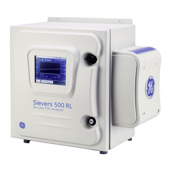
Chapter 1. Introduction The Sievers 500 RL On-Line TOC Analyzer from GE Analytical Instruments is a high-sensitivity Analyzer used to measure the concentration of total organic carbon (TOC), total inorganic carbon (TIC), and total carbon (TC = TOC + TIC) in water samples (for patent information, see the section called “Trademarks and Patents” on page 14). - Page 38 Special conditions in operating environments may require modifications to the recommendations in this manual. Specific instructions provided by GEAI service or technical support personnel supersede the information provided in this manual. GE Analytical Instruments ©2010 38 of 226 DLM 74001-04 Rev. A...
-
Page 39: Chapter 2: System Description
1 °C to 95 °C (34 °F to 203 °F) (withstands short-term steam exposure)** Sample Pressure Up to 100 psig Interferences Insensitive to organic heteroatoms Calibration Stability Typically stable for 12 months Display Readout 3 significant digits GE Analytical Instruments ©2010 39 of 226 DLM 74001-04 Rev. A... - Page 40 IP 45 *Note: Stated analytical performance is achievable under controlled laboratory conditions that minimize operator and standards errors. **iOS and Super iOS only. For more information, see page 96. GE Analytical Instruments ©2010 40 of 226 DLM 74001-04 Rev. A...
-
Page 41: System Overview
Chapter 2: System Description System Overview The Sievers 500 RL On-Line TOC Analyzer consists of five major subsystems: Sample inlet system and sample pump, including the Integrated On-Line Sampling (iOS) System or Super iOS System. Oxidation reactor Measurement module, comprising: •... -
Page 42: Sample Flow Path
Sample Inlet Block, offering on-line monitoring only. Discrete samples can be measured by the Sievers 500 RL On-Line TOC Analyzer by inserting a filled 40 mL sample vial into the iOS System. Continuous monitoring is accomplished by plumbing a sample line to the inlet GE Analytical Instruments ©2010... - Page 43 TC and IC. Once the values are measured, TOC is calculated as the difference: TOC = TC - IC GE Analytical Instruments ©2010 43 of 226 DLM 74001-04 Rev. A...
-
Page 44: Additional System Components
Analyzer via the USB port to a USB flash storage device (provided) and then transferred to any computer that supports USB. The Sievers 500 RL On-Line TOC Analyzer also has three analog outputs (4-20 mA) which can be customized to track specific data values, four alarms, and two binary ports. -
Page 45: Chapter 3: Installation
Chapter 3. Installation Overview This chapter provides installation instructions for the Sievers 500 RL On-Line TOC Analyzer and will help familiarize you with Analyzer design and function. An interior overview diagram is available in the “Maintenance” chapter on page 140. If you need additional assistance, contact GE Analytical Instruments Technical Support at 800.255.6964. -
Page 46: Step 1: Unpack And Inspect The Analyzer
Analyzer from the box. Next, verify that all items are present: Sievers 500 RL On-Line TOC Analyzer Operation and Maintenance Manual Validation Support Package (VSP) Volume I... -
Page 47: Additional Installation Equipment
Step 3: Select a Location for the Analyzer The Sievers 500 RL On-Line TOC Analyzer is designed to be mounted on a wall or support stand. Allow a minimum of 5 cm clearance between the back of the Analyzer and the wall for heat dissipation; allow 30.5 cm of clearance on the sides, top, and bottom of the analyzer for the plumbing and electrical connections. -
Page 48: Step 4: Install Power And Control Wiring
Analyzer. Connecting to a Power Supply Installation of the Sievers 500 RL On-Line TOC Analyzer requires an external source of AC power connected to the enclosure using a water-tight conduit connector. The electrical connection should be performed by a qualified electrician. -
Page 49: Installing The Analog Outputs And Alarms
Starting from the left, the terminal blocks are as follows: The first terminal block (TB2) is for two alarm outputs and binary inputs. The second terminal block (TB1) is for two additional alarm outputs. GE Analytical Instruments ©2010 49 of 226 DLM 74001-04 Rev. A... -
Page 50: Alarm Outputs (Tb2)
Reserved Reserved Alarm 4 (NO*) Alarm 4 (NC*) Alarm 4 (Common) Alarm 3 (NO*) Alarm 3 (NC*) Alarm 3 (Common) * NC = normally closed, NO = normally open GE Analytical Instruments ©2010 50 of 226 DLM 74001-04 Rev. A... -
Page 51: Wiring The 4-20 Ma Connection
Max. Load 600 ohms 4-20 mA Output No external power required Isolated self power Voltage compliant to 20 V Rload Recorder Figure 3: Wiring Diagram for the 4-20 mA Connection GE Analytical Instruments ©2010 51 of 226 DLM 74001-04 Rev. A... -
Page 52: Wiring The Remote Start (Binary Input) Connection
8 (-) 7 (+) Conduit Internal to Analyzer Local Control External to Analyzer K1 = Custom Computer Terminal Figure 4: Wiring Option for Binary Input Using Analyzer’s Internal Supply GE Analytical Instruments ©2010 52 of 226 DLM 74001-04 Rev. A... -
Page 53: Step 5: Installing The Printer, Usb, And Serial Connections
Before installing the printer cable, USB flash drive, or serial cable, you must first remove the cover plate from the Analyzer. Loosen the two thumb screws on the cover plate and remove the plate. Figure 6: Input and Output Connectors GE Analytical Instruments ©2010 53 of 226 DLM 74001-04 Rev. A... -
Page 54: Installing The Printer
Installing the Printer The Analyzer has a 25-pin parallel (Centronics) printer port for connecting an optional printer. The printer must be IBM compatible or Epson FX 850 compatible. GE Analytical Instruments sells Epson, Seiko, and Citizen printers for use with the Analyzer. -
Page 55: Wiring The Ethernet Cable
After water flow to the sample inlet system has been established, the flow rate should be adjusted so that flow out of the waste line is between 50 -300 mL/min. The flow rate is controlled by a needle valve, GE Analytical Instruments ©2010 55 of 226... -
Page 56: Step 7: Fill The Di Water Cartridge
Lift the spring clip (see Figure 8 on page 57) at the top of the DI water cartridge, and rotate the cartridge clockwise (as viewed from the top) so it slides out of the retaining hooks. GE Analytical Instruments ©2010 56 of 226... -
Page 57: Filling The Di Water Cartridge
To avoid scratches, do not use a metal tool to remove the John Guest fittings on the DI water cartridge. Always use the John guest tool provided in the Analyzer’s accessories kit. GE Analytical Instruments ©2010 57 of 226 DLM 74001-04 Rev. A... -
Page 58: Removing The John Guest Fitting
16. Connect the fitting labeled “B” to the barb labeled “B” on the top of the cartridge. 17. Connect the fitting labeled “D” to the barb labeled “D” on the top of the cartridge. GE Analytical Instruments ©2010 58 of 226... -
Page 59: Step 8: Configure Basic Analyzer Settings
Enabling DataGuard or Password Protection (Optional) The Sievers 500 RL On-Line TOC Analyzer offers two levels of security, one included with the Analyzer and the other available for purchase as an upgrade from GE Analytical Instruments. The Password Protection feature is included with the Analyzer and provides a basic level of security. -
Page 60: Enabling Dataguard
Proceed to the section “Establishing a New Administrator Account for DataGuard” below to complete the DataGuard activation. After installation is complete, you can add unique user accounts to the Analyzer. Refer to Chapter 5: Password Protection and DataGuard for more information. GE Analytical Instruments ©2010 60 of 226 DLM 74001-04 Rev. A... -
Page 61: Establishing A New Administrator Account For Dataguard
• Time Zone — Allows you to set a text descriptor for the time zone. Usually this is a three-letter code, such as “EST” for Eastern Standard Time or “GMT” for Greenwich Mean Time. GE Analytical Instruments ©2010 61 of 226... -
Page 62: Naming The Analyzer Location (Optional)
Before taking measurements, review the Archive Data setting to ensure that data is collected in the best way for your environment. When Archive Data is set to On, the Analyzer will not overwrite the oldest data and GE Analytical Instruments ©2010 62 of 226... -
Page 63: Setting Up The Printer (Optional)
Press the Back button and then press the Menu button. If you have a printer attached to the Analyzer, you can print these settings for future reference by following these steps: GE Analytical Instruments ©2010 63 of 226 DLM 74001-04 Rev. A... -
Page 64: Set Up Data I/O
Close the Analyzer case. The Analyzer is now ready to take valid TOC measurements. If you want to customize additional settings, do so now; consult Chapter 4: Basic Analyzer Operation for details. GE Analytical Instruments ©2010 64 of 226 DLM 74001-04 Rev. A... -
Page 65: Step 10: Install Datashare 500 Software
If you have DataShare 500 software to manage from your Analyzer, install it now. Consult the DataShare 500 Operation and Maintenance Manual, located on the software CD or at www.geinstsruments.com in The Library > Manuals), for instructions. GE Analytical Instruments ©2010 65 of 226 DLM 74001-04 Rev. A... - Page 66 Chapter 3: Installation GE Analytical Instruments ©2010 66 of 226 DLM 74001-04 Rev. A...
-
Page 67: Chapter 4: Basic Analyzer Operation
Chapter 4. Basic Analyzer Operation Overview The Sievers 500 RL On-Line TOC Analyzer utilizes a touch-sensitive color LCD for all menu selection activities. An overview of the menu structure is given in “The Menu Screen” on page 69. An overview of hardware features starts on page 96. -
Page 68: Figure 10 The Sievers 500 Rl On-Line Toc Analyzer Main Screen
Data area Status area Figure 10: The Sievers 500 RL On-Line TOC Analyzer Main Screen The Main screen is divided into three areas: The Header contains the name of the screen, the date and time, and status icons representing the following conditions: ... -
Page 69: Taking Toc Measurements
If the sample conditions for your application remain relatively constant, you should seldom need to configure the settings here. Setting the Analyzer Mode The Sievers 500 RL On-Line TOC Analyzer can operate in up to four different modes, depending on your configuration. To set the Analyzer mode, follow these steps: GE Analytical Instruments ©2010 69 of 226 DLM 74001-04 Rev. -
Page 70: Grab Mode Measurement Settings
When selecting Grab mode (available on configurations with an iOS or Super iOS), you need to specify the number of replicate measurements and rejects as follows: On the Setup tab, press the Configure Mode button. GE Analytical Instruments ©2010 70 of 226 DLM 74001-04 Rev. A... -
Page 71: Managing Data History
Figure 12: The Data Tab Setting up Data History The data history can accomodate approximately 33,000 entries (at least 90 days of usage). GE Analytical Instruments ©2010 71 of 226 DLM 74001-04 Rev. A... -
Page 72: Archiving Data History
Select the Data tab. Press the View button to display the data history. Press the Setup button to change the type of data displayed in the data history list. GE Analytical Instruments ©2010 72 of 226 DLM 74001-04 Rev. A... - Page 73 Because the Analyzer uses acidified standards, conductivity data gathered during some system protocols may exceed the maximum range. In these cases, the Analyzer will show a conductivity reading of >60 µS/cm for raw conductivity (rCond) or >30 µS/cm for temperature-corrected conductivity (tCond). GE Analytical Instruments ©2010 73 of 226 DLM 74001-04 Rev. A...
-
Page 74: Graphing Data History
Enter, and press the Back button. Note: Setup Main Settings specified in the screen affect the display of the graph on the Data screen, in addition to the graph displayed under the tab. GE Analytical Instruments ©2010 74 of 226 DLM 74001-04 Rev. A... -
Page 75: Printing Data History
Press the Print button to print the data. Note: Prior to printing, you may want to confirm your printer settings. See “Configuring Printer Settings” on page 80 for more information. GE Analytical Instruments ©2010 75 of 226 DLM 74001-04 Rev. A... -
Page 76: Exporting Data History
Menu selections under the I/O tab allow you to configure data for alarms, analog output, binary input, serial output and printing. Figure 15: The I/O Tab (With Ethernet Port Installed) GE Analytical Instruments ©2010 76 of 226 DLM 74001-04 Rev. A... -
Page 77: Setting Up Analog Output
Setting Up Analog Output The Sievers 500 RL On-Line TOC Analyzer has three 4-20 mA outputs. Select the output range for the 4-20 mA analog outputs by following the steps below. Instructions for wiring the 4-20mA output can be found in the “Installation”... -
Page 78: Adjusting Analog Output Values
TOC Analyzers and you want to use a serial output format compatible with the older format, press the 400 ES button. Otherwise, 500 RL should be selected as the output format. The default format is 500 RL. GE Analytical Instruments ©2010 78 of 226... -
Page 79: Interpreting Serial Output
Analyzer, see “Using HyperTerminal” on page 179 in the Appendix. Note: For long distance connections (up to 1,000 feet or 305 meters), GE Analytical Instruments recommends use of either a RS-232 current loop converter or a RS-422 converter. You can also use an Ethernet connection. -
Page 80: Issuing Serial Commands To The Analyzer
Set Header Frequency to First Page or All Pages to specify when a header will print. The header includes basic information about the Analyzer, including the firmware version, Analyzer serial number, and the current date. GE Analytical Instruments ©2010 80 of 226 DLM 74001-04 Rev. A... -
Page 81: Activating Binary Input
• Power Fail — The alarm is triggered when the Analyzer loses power. • Error — The alarm is triggered when the Analyzer issues an error. • Warning — The alarm is triggered when the Analyzer issues a warning. GE Analytical Instruments ©2010 81 of 226 DLM 74001-04 Rev. A... -
Page 82: Using The Ethernet Connection And Modbus
• Press the Method button and select either DHCP or Fixed. If you select Fixed, press the IP Address and IP Mask buttons and enter the appropriate addresses. Press the Back button. GE Analytical Instruments ©2010 82 of 226 DLM 74001-04 Rev. A... -
Page 83: Table
Coils (read) State 2000 Stop Coils (write) 2000 Stop 2001 Input Registers (read) Instrument Family 3010 Instrument Model 3011 Serial Number 3012 Firmware Version (Major) 3015 Firmware Version (Minor) 3016 GE Analytical Instruments ©2010 83 of 226 DLM 74001-04 Rev. A... -
Page 84: Table
Sample Temperature Units 3702 Holding Registers not used (read/write) *All Coils (write) and Input registers are 16-bit unsigned. Notes: Values are IEEE 32-bit floats split into two 16-bit registers. GE Analytical Instruments ©2010 84 of 226 DLM 74001-04 Rev. A... -
Page 85: Managing Maintenance Information
The Maintenance tab also provides access to calibration and verification functions and other advanced features; consult Chapter 6: Calibration and System Protocols for details on these functions. GE Analytical Instruments ©2010 85 of 226 DLM 74001-04 Rev. A... -
Page 86: Displaying Consumables Status
Press the Clock button. Press each date component button, enter the appropriate value, and press the Enter button. Press each time component button, enter the appropriate value, and press the Enter button. GE Analytical Instruments ©2010 86 of 226 DLM 74001-04 Rev. A... -
Page 87: Reviewing Warnings And Errors
“Warnings and Error Messages” on page 154. Press the Acknowledge button for each error and warning to clear the error/warning status of the instrument and automatically reset the alarm(s). GE Analytical Instruments ©2010 87 of 226 DLM 74001-04 Rev. A... -
Page 88: Displaying System Information
Chapter 4: Basic Analyzer Operation Displaying System Information If you need to contact GE Analytical Instruments about your Analyzer, you can find most essential information on a single screen. Select the Maintenance tab. Press the System Info button. The following unit information is displayed: •... -
Page 89: Saving System Settings
USP 645 or EP WFI 2.2.38. Conductivity must be activated, along with one of the available pharmacopeia selections (JP TOC and JP COND excepted) for this button to display. GE Analytical Instruments ©2010 89 of 226 DLM 74001-04 Rev. A... -
Page 90: Adjusting Display Contrast Settings
Press the Advanced button. Press the Advanced Setup button. Press the Display Mode button. Select the values you want displayed on the Main screen: TOC/tCond, TOC/rCond/Temp, TOC, or TOC/ IC/TC, TOC/IC/rCond, TOC/IC/tCond. GE Analytical Instruments ©2010 90 of 226 DLM 74001-04 Rev. A... -
Page 91: Specifying The Pharmacopeia
Water for Injection: IP 2.4.30 Total Organic Carbon in Water and IP 2.4.9 Conductivity for Water for Injections in Bulk. The TOC test is passed if the measured TOC of the sample (r ) is not greater than (r GE Analytical Instruments ©2010 91 of 226 DLM 74001-04 Rev. A... -
Page 92: Pass/Fail Reporting
TOC analyzer will report a Pharmacopeia “Failure” result, if any of the selected tests fail. Conductivity and TOC tests can be independently tested with the alarms, an alarm can be set for each of TOC Limit, Cond Limit, or GE Analytical Instruments ©2010 92 of 226... -
Page 93: Selecting The Program Language
Press the Flow Restart button and set it to On or Off. Setting the Flow Restart to On means the Analyzer will automatically begin analysis again after a temporary stoppage of sample flow, if it was taking GE Analytical Instruments ©2010 93 of 226... -
Page 94: Specifying Auto Restart Settings
Press the Frequency button and use the number keypad to enter how often you want to program the TOC Autozero function to work. The Frequency is measured in days; if you enter 7 the TOC Autozero will GE Analytical Instruments ©2010 94 of 226... -
Page 95: Draining The Ios System
Press the Activate Options button. Press the OK button and wait for the Analyzer to detect the USB flash drive. Press the Activate button to activate the new feature. GE Analytical Instruments ©2010 95 of 226 DLM 74001-04 Rev. A... -
Page 96: Basic Hardware Operation Issues
TOC values, or an increase in the standard deviation values. The iOS System GE Analytical Instrument offers three inlet systems for use with the Sievers 500 RL On-Line TOC Analyzer: a sample inlet block for dedicated on-line analysis, a standard Integrated On-Line Sampling (iOS) System, with one vial port, and a Super iOS, with four vial ports. - Page 97 System, slide the door open and wait 30 seconds to allow sample to completely drain. Inserting a vial before draining can result in potentially hot water spray projecting upward out of the standard iOS System. GE Analytical Instruments ©2010 97 of 226 DLM 74001-04 Rev. A...
-
Page 98: The Sample Inlet Block
Figure 21: The Sample Inlet Block Warning The Sample Inlet Block may be hot. If the sample water is hot, be careful to avoiding touching the Sample Inlet Block. GE Analytical Instruments ©2010 98 of 226 DLM 74001-04 Rev. A... -
Page 99: Vial Set Cartridges
30 minutes. When exposed to steam, the Analyzer should be powered off or in standby mode, and not in analysis mode. After exposure to steam, allow the Analyzer to cool before returning to Analysis mode. Observe the following cool-down intervals before starting analysis after steam exposure: GE Analytical Instruments ©2010 99 of 226 DLM 74001-04 Rev. A... - Page 100 Chapter 4: Basic Analyzer Operation Ambient Temperature Time Interval Below 20 °C 15 minutes 20 - 30 °C 30 minutes 30 - 40 °C 90 minutes GE Analytical Instruments ©2010 100 of 226 DLM 74001-04 Rev. A...
-
Page 101: Chapter 5: Password Protection And Dataguard
Chapter 5. Password Protection and DataGuard Overview The Sievers 500 RL On-Line TOC Analyzer includes Password Protection using one user name and password for all users. You can activate or deactivate this feature, as needed. Using Password security, there are two options for Menu Lockout (On and Off) that define when a user must enter the user name and password. -
Page 102: Figure 22 Menu Map - Menu Lockout Off (Requires Calibration Passwords)
Chapter 5: Password Protection and DataGuard Figure 22: Menu Map — Menu Lockout Off (Requires Calibration Passwords) GE Analytical Instruments ©2010 102 of 226 DLM 74001-04 Rev. A... -
Page 103: Enabling Password Protection
Analyzer. Once Password Protection is enabled, all users must enter the default User ID and Password, i.e., there is ONLY one User ID and one password GE Analytical Instruments ©2010 103 of 226 DLM 74001-04 Rev. A... -
Page 104: To Enable Password Protection
The default setting is Menu Lockout Off. For more information, see Figure 22: Menu Map — Menu Lockout Off (Requires Calibration Passwords) on page 102. GE Analytical Instruments ©2010 104 of 226 DLM 74001-04 Rev. A... -
Page 105: Disabling Password Protection
DataGuard offers support for regulation 21 CFR Part 11, providing multiple levels of user access to the Analyzer via up to 100 unique User IDs and maintaining an audit trail of all user operations. DataGuard must be purchased as an upgrade from GE Analytical Instruments. Once it is enabled, it cannot be disabled. Enabling DataGuard DataGuard is locked until it is activated by following the steps below. -
Page 106: Adding User Ids
Note: the Analyzer. If you forget the login information for the new administrator account that you have created, contact GE Analytical Instruments for assistance. Adding User IDs After DataGuard has been enabled, you can add a User ID by following these steps: Select the DataGuard tab. -
Page 107: Editing User Information
• Password — Press the Password button to change the Password for the selected User ID. Press the Menu button to save changes and return to the DataGuard screen. GE Analytical Instruments ©2010 107 of 226 DLM 74001-04 Rev. A... -
Page 108: Configuring Login Settings
If users forget their Passwords, the administrator must assign new Passwords by following these steps: Log in to the Analyzer with an administrator-level User ID and Password. Select the DataGuard tab. Press the Edit User button. GE Analytical Instruments ©2010 108 of 226 DLM 74001-04 Rev. A... -
Page 109: Reactivating Inactivated User Accounts
Press the Archive Users button. You will be warned that user accounts set to Inactive will be removed. Make sure you have a USB storage device attached to the Analyzer. Press the OK button. GE Analytical Instruments ©2010 109 of 226 DLM 74001-04 Rev. A... -
Page 110: Viewing, Exporting, And Printing Audit Trails
MMM yyyy hh:mm:ss (columns 23-33) 17 OCT 2004 Time 10:22:47 Action 20 alpha-numeric characters (columns 44-63) PASSWORD SET Old Value Alpha-numeric characters (columns 65-end of QUALITY 01 line) GE Analytical Instruments ©2010 110 of 226 DLM 74001-04 Rev. A... -
Page 111: Logging Out
To log out, press the Logout button on any display screen. If the Logout button is not displayed on the current screen, press the Back or Menu button until any of the main tabs (Setup, Data, I/O, Maintenance, or DataGuard) display, and then press the Logout button. GE Analytical Instruments ©2010 111 of 226 DLM 74001-04 Rev. A... - Page 112 Chapter 5: Password Protection and DataGuard Table 7: Record of User IDs Date User ID User’s Name Date Created Archived GE Analytical Instruments ©2010 112 of 226 DLM 74001-04 Rev. A...
-
Page 113: Chapter 6: Calibration And System Protocols
The Sievers 500 RL On-Line TOC Analyzer can be calibrated using one of two methods: single-point calibration at 1.5 ppm; or multi-point calibration at 500 ppb, 1.0 ppm, and 1.5 ppm. GE Analytical Instruments recommends single-point calibration for most applications. -
Page 114: Required Calibration Supplies
(System Suitability, Accuracy & Precision, Linearity, Robustness, Specificity, and JP Protocol) can be purchased individually, or as a combined Validation Set. To purchase standards in North America or Canada, contact GE Analytical Instruments by phone at 800.255.6964 or 303.444.2009. To purchase standards in the United Kingdom, contact GE Analytical Instruments at 44(0) 161866 9337. -
Page 115: Preparing For Calibration
Warning Standards for the Sievers 500 RL On-Line TOC Analyzer are acidified. If you prepare your own standards and use glass vials, ensure that you acidify the standards to a pH of 3, or the system protocols will yield poor results. -
Page 116: Perform Annual Maintenance Tasks
Press the Binary Input button. Press the Binary Input Off button. When you are finished performing calibration or other system protocols, press On to reset the Binary Input function. GE Analytical Instruments ©2010 116 of 226 DLM 74001-04 Rev. A... -
Page 117: Performing A Single-Point Calibration
Press the Next button, and then press the No Set button. If the label of the Conductivity Standard shows a value of 25 µS/cm HCl, (or your configuration does not measure for conductivity), press Next to continue. GE Analytical Instruments ©2010 117 of 226 DLM 74001-04 Rev. A... - Page 118 Rinse activity. Take out the rinse cartridge or vials when completed. 16. If you have a standard iOS System, remove the standards and slide the iOS door closed. GE Analytical Instruments ©2010 118 of 226 DLM 74001-04 Rev. A...
-
Page 119: Figure 24 Reviewing Tc And Ic Values From A Single-Point Calibration
17. You should now verify the calibration. Proceed to “Accuracy, Precision, and Calibration Verification” on page 124 for instructions. Figure 24: Reviewing TC and IC Values from a Single-Point Calibration Figure 25: Reviewing Conductivity Values from a Single-Point Calibration GE Analytical Instruments ©2010 119 of 226 DLM 74001-04 Rev. A... -
Page 120: Performing A Multi-Point Calibration
Press the Next button, and then press the No Set button. If the label of the Conductivity Standard shows a value of 25 µS/cm HCl, (or your configuration does not measure for conductivity), press Next to continue. GE Analytical Instruments ©2010 120 of 226 DLM 74001-04 Rev. A... - Page 121 12. Part 3 of the summary displays data for the blank, 1.0 ppm standard, and 500 ppb standard (see Figure 27). 13. Press the Print button if you want to print the Calibration results. GE Analytical Instruments ©2010 121 of 226 DLM 74001-04 Rev. A...
-
Page 122: Figure 26 The First Summary Screen In A Multi-Point Calibration
18. You should now verify the calibration. Proceed to “Accuracy, Precision, and Calibration Verification” on page 124 for instructions. Figure 26: The First Summary Screen in a Multi-Point Calibration GE Analytical Instruments ©2010 122 of 226 DLM 74001-04 Rev. A... -
Page 123: Figure 27 The Second Summary Screen In A Multi-Point Calibration
Chapter 6: Calibration and System Protocols Figure 27: The Second Summary Screen in a Multi-Point Calibration Figure 28: The Third Summary Screen in a Multi-Point Calibration GE Analytical Instruments ©2010 123 of 226 DLM 74001-04 Rev. A... -
Page 124: Accuracy, Precision, And Calibration Verification
Chapter 6: Calibration and System Protocols Accuracy, Precision, and Calibration Verification The Sievers 500 RL On-Line TOC Analyzer automatically calculates accuracy, precision, and calibration verification values. Use this procedure to confirm that the Analyzer’s current calibration is accurate. GE Analytical Instruments recommends performing a verification after replacement of consumables, such as the pump heads (with pump tubing), DI water cartridge, or UV lamp, and after calibration. - Page 125 The standard deviation and relative standard deviation are calculated as follows: Standard Deviation = – ------------------------------------- - Each Result n n 1 – Number of Measure ments repetition rejections GE Analytical Instruments ©2010 125 of 226 DLM 74001-04 Rev. A...
-
Page 126: Figure
13. If you have a standard iOS System, remove the standards and slide the iOS door closed. Figure 29: The Accuracy, Precision, and Verification Summary Screen, Part 1 Figure 30: The Accuracy, Precision, and Verification Summary Screen, Part 2 GE Analytical Instruments ©2010 126 of 226 DLM 74001-04 Rev. A... -
Page 127: Performing Pharmacopeia Tests
Chapter 6: Calibration and System Protocols Performing Pharmacopeia Tests The Sievers 500 RL TOC Analyzer is designed to comply with various Pharmacopeia testing. Additional Method Specificity and Method Robustness protocols, compliant with ICH Q2(R1), are also available as optional protocols from GE Analytical Instruments. - Page 128 Limit alarm, when activated (see “Setting Alarm Values” on page 83). Press the Yes button to confirm that you want to accept the new value. 10. Press the Exit. GE Analytical Instruments ©2010 128 of 226 DLM 74001-04 Rev. A...
-
Page 129: Jp Protocol
(Optional) If DataGuard is enabled, log in to the Analyzer with a UserID that has a User Level of Quality Assurance or Administrator and the appropriate Password. If Password protection is enabled, log in to the Analyzer with the UserID and Password. GE Analytical Instruments ©2010 129 of 226 DLM 74001-04 Rev. A... - Page 130 • Insert the Reagent Water (RW) standard into the iOS System, and then press Next. • When prompted by the Analyzer, remove the RW standard and insert the SDBS standard into the iOS System, and press Next. GE Analytical Instruments ©2010 130 of 226 DLM 74001-04 Rev. A...
- Page 131 Rinse activity. Take out the rinse cartridge or vials when completed. 13. If you have a standard iOS System, remove the standards and slide the iOS door closed. The Pass/Fail test uses rounded values. GE Analytical Instruments ©2010 131 of 226 DLM 74001-04 Rev. A...
-
Page 132: Reviewing Calibration And Verification History
For calibrations, result summaries are stored in Cal/Ver History memory only if the calibration was applied. Table 12: Maximum Stored Results by Protocol Type Maximum Number of Stored System Protocol Type Results System Suitability Accuracy/Precision/Verification Single Point Calibration Multipoint Calibration Sample Cell Calibration Linearity GE Analytical Instruments ©2010 132 of 226 DLM 74001-04 Rev. A... -
Page 133: High Blank Toc Warnings/Errors
To disable the reporting of high Blank TOC warnings and errors during system protocols, on the Advanced Cal menu, press the Blank Limit Test button to display the Blank Limit Test screen . GE Analytical Instruments ©2010 133 of 226... -
Page 134: Single-Point Calibration Worksheet
________ ________ ________ ________ ________ ________ ________ ________ ________ Diff ________ ________ ________ ________ ________ ________ ________ Calibration Results: Passed Failed Calibration Action: Applied Canceled GE Analytical Instruments ©2010 134 of 226 DLM 74001-04 Rev. A... -
Page 135: Multi-Point Calibration Worksheet
________ ________ ________ ________ ________ ________ ________ ________ ________ ________ ________ Diff ________ ________ ________ ________ ________ Calibration Results: Passed Failed Calibration Action: Applied Canceled GE Analytical Instruments ©2010 135 of 226 DLM 74001-04 Rev. A... -
Page 136: Accuracy, Precision, And Verification Worksheet
• Conductivity Precision: RSD of last three compensated conductivity measurements on 25 µS/cm standard 7% • TOC Accuracy: % Difference 2% • Conductivity Accuracy: % Difference GE Analytical Instruments ©2010 136 of 226 DLM 74001-04 Rev. A... -
Page 137: System Suitability Worksheet
Response Efficiency = ------------------------ - (Rs-Rw) Response Limit = Rs - Rw Acceptance criteria for USP System Suitability is response efficiency between 85% and 115% Pass Fail GE Analytical Instruments ©2010 137 of 226 DLM 74001-04 Rev. A... -
Page 138: Jp Protocol Worksheet
TOC Blank Average 250 ppb Blank-Corrected Average 450 ppb Conductivity Difference ± RSD 2% Sample temperature is between15°C to 30°C Pass Fail GE Analytical Instruments ©2010 138 of 226 DLM 74001-04 Rev. A... -
Page 139: Chapter 7: Maintenance
Refer to Table 13 below for the recommended maintenance schedule. The in-line filter, UV lamp, DI water cartridge, and sample pump tubing (including pump heads) must be purchased from GE Analytical Instruments. If you need additional assistance, contact GE Analytical Instruments Technical Support at 800.255.6964. Training is also available from GE Analytical Instruments. -
Page 140: Checking And Refilling The Di Water Level
Turn off power to the Analyzer with the main power switch. Open the Analyzer front panel. Locate the DI water cartridge at the center of the Analyzer (see Figure 32 on page 140). GE Analytical Instruments ©2010 140 of 226 DLM 74001-04 Rev. A... -
Page 141: Replacing The Uv Lamp
Figure 33: Filling the DI Water Cartridge Replacing the UV Lamp The intensity of the UV lamp, particularly the emission of short-wavelength radiation, decreases over time. Replace the lamp after every six months of operation. GE Analytical Instruments ©2010 141 of 226 DLM 74001-04 Rev. A... - Page 142 Put on the glove provided with the new UV lamp, to avoid leaving fingerprints on the quartz window of the lamp. Remove the new lamp from the packet and the nut and ferrules from the zip-top bag. GE Analytical Instruments ©2010 142 of 226...
-
Page 143: Figure 34 Relative Positioning Of Components In The Uv Lamp Assembly
15. Plug in the main power cord and turn the Analyzer on with the main power switch. 16. Enter the installation date for the UV lamp by following the procedures in “Setting the Installation or Date for New Consumables” on page 149. GE Analytical Instruments ©2010 143 of 226 DLM 74001-04 Rev. A... -
Page 144: Replacing The Sample Pump Tubing And Pump Heads
The sample pump tubing and pump heads must be purchased from GE Analytical Instruments; use of tubing from other sources or failure to replace the tubing on the prescribed replacement schedule will affect Analyzer functionality. -
Page 145: Replacing The Di Water Cartridge
If the Analyzer is taking measurements, press the Stop Analysis button. Turn off the Analyzer by using the main power switch; also switch off the external circuit breaker for the Analyzer. GE Analytical Instruments ©2010 145 of 226 DLM 74001-04 Rev. A... - Page 146 DI water cartridge. If large air bubbles are present, tap or manipulate the tubing to work the air bubbles out. 22. Keep the Analyzer powered on for 2 minutes. 23. After 2 minutes, turn the Analyzer off. GE Analytical Instruments ©2010 146 of 226 DLM 74001-04 Rev. A...
-
Page 147: Figure 37 John Guest Fittings On The Di Water Cartridge (Detail)
36. Enter the installation date for the pump heads by following the procedures in “Setting the Installation or Date for New Consumables” on page 149. Figure 37: John Guest fittings on the DI Water Cartridge (Detail) GE Analytical Instruments ©2010 147 of 226 DLM 74001-04 Rev. A... -
Page 148: Replacing The In-Line Filter Element
If the filter element clogs too frequently, contact GE Analytical Instruments to receive help in the selection of larger-capacity filters. As the filter is used, the flow rate of water through the iOS System will decrease and can even stop. -
Page 149: Setting The Installation Or Date For New Consumables
When Password protection or DataGuard is activated, not all users are able to modify settings on this screen. See “Menu Map — DataGuard (Optional Upgrade)” on page 103 or “Using DataGuard” on page 105 for more information. GE Analytical Instruments ©2010 149 of 226 DLM 74001-04 Rev. A... -
Page 150: Cleaning The Analyzer
30 seconds by selecting the following option: Press the Menu button and select the Maintenance tab. Press the Advanced button, press the Advanced Setup button, and then press the Clean Screen button. GE Analytical Instruments ©2010 150 of 226 DLM 74001-04 Rev. A... -
Page 151: Table 15 Sievers 500 Rl On-Line Toc Analyzer 3-Year Maintenance Worksheet
Chapter 7: Maintenance Table 15: Sievers 500 RL On-Line TOC Analyzer 3-Year Maintenance Worksheet Item Period Installation Date Notes UV Lamp 6 months DI Water Filled 6 months Pump Heads 12 months UV Lamp 12 months DI Water Filled 12 months... - Page 152 Chapter 7: Maintenance GE Analytical Instruments ©2010 152 of 226 DLM 74001-04 Rev. A...
-
Page 153: Chapter 8: Troubleshooting
This chapter provides the starting point for troubleshooting basic issues with your Analyzer. If you need additional assistance, in the U.S. contact GE Analytical Instruments Technical Support at 800.255.6964. In other parts of the world, contact your local GE Analytical instruments representative. -
Page 154: Warnings And Error Messages
Explanation: Based on the history of usage, the Analyzer estimates that only 10% of the resin bed life remains. Order a new resin bed from GE Analytical Instruments now to avoid down time when the resin bed expires. 8 - User List Warning Message: “The user list is nearly full. - Page 155 25 - History Data Warning Message: “A problem has been corrected in the history data. Contact GE if the warning persists.” Explanation: The Analyzer has detected a problem reading or writing to the data history memory; as much of the data history as possible is reconstructed.
- Page 156 Analyzer’s accessories kit, it is possible your USB device is not compatible with the Analyzer. For a list of known compatible USB flash memory drives, follow the Sievers 500 RL Analyzer link on our Web page, www.geinstruments.com.
- Page 157 System in the correct order. Consult Chapter 6: Calibration and System Protocols for the correct vial order. 56 - Sample Pump Error Message: “The sample pump is not pumping. Please refer to the Oper. and Maint. Manual. Contact GE is problem persists.”...
- Page 158 Autozero when two consecutive negative measurements occur. If negative readings occur after a second TOC Autozero, this warning is issued, and the Analyzer will abort analysis. Consult troubleshooting techniques under “Step 3: Review Solutions for Basic Problems” on page 159, and contact GE Analytical Instruments Technical Support if negative readings persist.
-
Page 159: Step 2: Visual Inspection
Note that if tubing has become bent, kinked, or otherwise damaged, a tubing replacement kit is available from GE Analytical Instruments Technical Support. Step 3: Review Solutions for Basic Problems If a visual inspection of the Analyzer does not help you identify the source of the problem you are experiencing, consult the specific problems discussed in this section. -
Page 160: The Analyzer Will Not Power On
While the Analyzer is operating, open the Analyzer front panel and make sure the sample pump is turning. If the pump is not turning and the Analyzer is operating (the display screen indicates that analysis is taking place), contact GE Analytical Instruments Technical Support for instructions. Warning To avoid potentially dangerous shock, do not touch anything inside the Analyzer while observing the sample pump. -
Page 161: Figure 40 Disconnecting The Tubing From The Front Solenoid Valve
Press the Test Pumps button, and then press the DI Pump button. Cycle the pump on and off a few times, by pressing the On and Off buttons, finally leaving it set to On. If there is no flow, contact GE Analytical instruments for further assistance. -
Page 162: Figure 41 The Inlet And Outlet Connections Inside The Analyzer
(on the right). The second pair of tubes (on the right) should be connected to the barbs that normally connect to the first pair of tubes (on the left). Figure 42: The Sample Pump Tubing Connections GE Analytical Instruments ©2010 162 of 226 DLM 74001-04 Rev. A... -
Page 163: Negative, High, Or Erratic Measurements
µS/cm Conductivity Standard (as HCl). If you have a Super iOS, place this standard in vial port 1. Make sure the Analyzer is not taking measurements. Press the Menu button and select the Maintenance tab. Press the Cal/Ver/Validate button. Press the Sample Cell Cal button. GE Analytical Instruments ©2010 163 of 226 DLM 74001-04 Rev. A... -
Page 164: Sample Cell Zero
If the Analyzer is taking measurements, press the Stop Analysis button. Press the Menu button, select the Maintenance tab and press the Cal/Ver/Validate button. Press Run TOC Autozero. GE Analytical Instruments ©2010 164 of 226 DLM 74001-04 Rev. A... -
Page 165: Toc Offset
Counting from the top, press the fourth button in the left column (Advanced). Press the fourth button in the left column (Advanced Setup). Press the fifth button in the left column (Select Language). GE Analytical Instruments ©2010 165 of 226 DLM 74001-04 Rev. A... -
Page 166: Problems With Vial Set Cartridges
Restore power to the Analyzer. If the problem persists, repeat steps 1 through 3. GE Analytical Instruments ©2010 166 of 226 DLM 74001-04 Rev. A... -
Page 167: Step 4: Contact Technical Support
In some instances, after consulting with GE Analytical Instruments Technical Support, it will be necessary to return the Analyzer to the factory for repairs. Only return the Analyzer to GE Analytical Instruments if Technical Support has issued you a Return Authorization (RA) number. - Page 168 22. Close and latch the Analyzer front panel. You can now repackage the Analyzer and ship it to GE Analytical Instruments. For international shipments, coordinate with an GE Analytical Instruments representative to ensure quick passage through customs.
- Page 169 Chapter 8: Troubleshooting Figure 44: Removing the John Guest Fittings GE Analytical Instruments ©2010 169 of 226 DLM 74001-04 Rev. A...
- Page 170 Chapter 8: Troubleshooting GE Analytical Instruments ©2010 170 of 226 DLM 74001-04 Rev. A...
-
Page 171: Appendix A: Analyzer Dimension Diagrams
Appendix A: Analyzer Dimension Diagrams Diagrams show Analyzer dimensions and required clearances as follows: inches [millimeters]. Figure 45: Analyzer Dimensions, with Standard iOS System GE Analytical Instruments ©2010 171 of 186 DLM 74001-04 Rev. A... -
Page 172: Figure 46 Right-Side Analyzer Dimensions, With Standard Ios System
Appendix A Figure 46: Right-Side Analyzer Dimensions, with Standard iOS System GE Analytical Instruments ©2010 172 of 186 DLM 74001-04 Rev. A... - Page 173 Appendix A Figure 47: Analyzer Dimensions, with Super iOS System GE Analytical Instruments ©2010 173 of 186 DLM 74001-04 Rev. A...
-
Page 174: Figure 48 Right-Side Analyzer Dimensions, With Super Ios System
Appendix A Figure 48: Right-Side Analyzer Dimensions, with Super iOS System GE Analytical Instruments ©2010 174 of 186 DLM 74001-04 Rev. A... - Page 175 Appendix A Figure 49: Analyzer Dimensions, with Sample Inlet Block GE Analytical Instruments ©2010 175 of 186 DLM 74001-04 Rev. A...
-
Page 176: Figure 50 Right-Side Analyzer Dimensions, With Sample Inlet Block
Appendix A Figure 50: Right-Side Analyzer Dimensions, with Sample Inlet Block GE Analytical Instruments ©2010 176 of 186 DLM 74001-04 Rev. A... - Page 177 Appendix A Figure 51: Left-Side Analyzer Dimensions GE Analytical Instruments ©2010 177 of 186 DLM 74001-04 Rev. A...
- Page 178 Appendix A GE Analytical Instruments ©2010 178 of 186 DLM 74001-04 Rev. A...
-
Page 179: Appendix B: Connecting To A Pc
“Determining Your Communications Port Number” on page 180. In the Com Settings window, specify the following settings: Bits Per Second:9600 (or rate that matches Analyzer setting) GE Analytical Instruments ©2010 179 of 186 DLM 74001-04 Rev. A... -
Page 180: Determining Your Communications Port Number
Scroll down to Ports (Com and LPT) and expand the menu by clicking the plus sign (+). The communication ports in use should be listed, along with device names. GE Analytical Instruments ©2010 180 of 186 DLM 74001-04 Rev. A... -
Page 181: Index
101 preparing for 115 reactivating User IDs 109 required supplies 114 Default User ID/Password 2 reviewing history 132 DI Water Cartridge single-point 117 adding water 140 single-point worksheet 134 GE Analytical Instruments ©2010 181 of 186 DLM 74001-04 Rev. A... - Page 182 Ion Exchange Resin. See Resin Bed for DataGuard accounts 108 iOS System for Password Protection 104 draining 95 Printing overview 96 calibration history 132 proper use 96 configuring settings 80 GE Analytical Instruments ©2010 182 of 186 DLM 74001-04 Rev. A...
- Page 183 115 forgotten passwords 108 Super iOS System reactivating 109 cartridge data 99 worksheet 112 draining 95 UV Lamp overview 96 replacing 141 setting installation date 149 GE Analytical Instruments ©2010 183 of 186 DLM 74001-04 Rev. A...
- Page 184 INDEX Verification accuracy, precision, and verification work- sheet 136 history, printing 132 reviewing history 132 Vial Sets cartridges 99 Warnings and Errors list of 154 reviewing 87 GE Analytical Instruments ©2010 184 of 186 DLM 74001-04 Rev. A...
- Page 185 Notes GE Analytical Instruments ©2010 185 of 186 DLM 74001-04 Rev. A...
- Page 186 Notes GE Analytical Instruments ©2010 186 of 186 DLM 74001-04 Rev. A...
Need help?
Do you have a question about the Sievers 500 RL and is the answer not in the manual?
Questions and answers