Table of Contents
Advertisement
Quick Links
Advertisement
Table of Contents

Related Manuals for Honeywell Stratos 2700


Summary of Contents for Honeywell Stratos 2700
- Page 1 Stratos™ 2700 Bioptic Scanner/Scale User’s Guide...
- Page 2 Disclaimer Honeywell International Inc. (“HII”) reserves the right to make changes in specifications and other infor- mation contained in this document without prior notice, and the reader should in all cases consult HII to determine whether any such changes have been made. The information in this publication does not rep- resent a commitment on the part of HII.
- Page 3 5627 BT Eindhoven The Netherlands Honeywell International Inc. shall not be liable for use of our product with equipment (i.e., power supplies, personal comput- ers, etc.) that is not CE marked and does not comply with the Low Voltage Directive.
-
Page 4: Laser Safety Statement
This product has required the extraction and use of natural resources for its production. It may contain hazardous sub- stances that could impact health and the environment, if not properly disposed. In order to avoid the dissemination of those substances in our environment and to diminish the pressure on the natural resources, we encourage you to use the appropriate take-back systems for product disposal. - Page 5 For patent information, refer to www.honeywellaidc.com/patents. Solids and Water Protection The Stratos 2700 has a rating of IP42, immunity of foreign particles and dripping water. Warning To reduce the possibility of heat-related injuries, avoid touching sections of the scanner that feel warm.
-
Page 7: Table Of Contents
Table of Contents Chapter 1 - Getting Started About This Manual .......................1-1 Printing Single Bar Codes ....................1-1 Dimensions ..........................1-1 Site Requirements .......................1-1 Vertical Clearance......................1-1 Ventilation and Spacing ....................1-1 Lighting...........................1-1 Service Access.......................1-1 Power Installation......................1-2 EAS Considerations .......................1-2 Power from Host ......................1-2 Unpacking Your Device .......................1-2 Configuring the 2700......................1-2 Features of the Stratos Bioptic.....................1-3... - Page 8 Chapter 3 - Programming the Bioptic Scanner Interface Introduction.......................... 3-1 Printing Single Bar Codes ....................3-1 Menu Bar Code Security Settings ..................3-1 Setting Custom Defaults...................... 3-1 Resetting the Custom Defaults.................... 3-2 Programming the Scanner Interface - Plug and Play ............3-2 RS232 Serial Port Interface....................
- Page 9 NCR Modifiers ........................3-32 NCR ACK/NAK ......................3-32 NCR Modes ......................... 3-32 Block Check Character ....................3-34 NCR Prefix........................3-34 NCR Suffix ........................3-34 NCR NOF (Not-on-File) Error ..................3-34 Do Not Wait for NCR Weight ..................3-35 NCR Weight Timeout....................3-35 Chapter 4 - Input/Output Settings Power Up Settings.......................
- Page 10 Scanner to Bioptic Communication ..................5-1 Scanner-Bioptic Packet Mode ..................5-1 ACK/NAK ........................5-1 Communication Timeout....................5-1 Aux Port Configuration Codes ..................... 5-2 Honeywell Scanner Aux Port Configuration..............5-2 ® Datalogic™ Magellan Aux Port Configuration ............. 5-2 NCR Bioptic Aux Port Configuration ................5-2 Wincor Nixdorf Beetle Aux Port Configuration...............
- Page 11 Chapter 7 - Data Editing Prefix/Suffix Overview ......................7-1 To Add a Prefix or Suffix:....................7-1 To Clear One or All Prefixes or Suffixes ................ 7-2 To Add a Carriage Return Suffix to All Symbologies ............. 7-2 Prefix Selections........................7-2 Suffix Selections ........................
- Page 12 Code 11 ..........................9-17 Code 128 ........................... 9-19 Code 128 Code Page ....................9-20 ISBT 128..........................9-20 GS1-128 ..........................9-26 Telepen..........................9-28 UPC-A ..........................9-29 UPC-A/EAN-13 with Extended Coupon Code ..................9-32 UPC-A Number System 4 Addenda Required............. 9-32 UPC-A Number System 5 Addenda Required............. 9-33 Coupon GS1 DataBar Output....................
- Page 13 GS1 Composite Codes...................... 9-66 UPC/EAN Version......................9-66 GS1 Emulation ........................9-67 TCIF Linked Code 39 (TLC39) ..................9-68 QR Code..........................9-68 Data Matrix ........................9-70 MaxiCode .......................... 9-71 Aztec Code ........................9-72 Chinese Sensible (Han Xin) Code..................9-73 Chapter 10 - EAS Settings EAS Deactivation.......................
- Page 14 Linear Symbologies .......................A-1 2D Symbologies......................A-2 Postal Symbologies .......................A-2 ASCII Conversion Chart (Code Page 1252)................A-3 Lower ASCII Reference Table.....................A-4 ISO 2022/ISO 646 Character Replacements ..............A-7 Unicode Key Maps ......................A-10 Appendix B - Auxiliary Honeywell Scanner Configuration Codes RS-232 ..........................B-1 USB Serial ...........................B-1 viii...
-
Page 15: Chapter 1 - Getting Started
Honeywell bar code scanners are factory programmed for the most common terminal and communications settings. If you need to change these settings, programming is accomplished by scanning the bar codes in this guide. -
Page 16: Power Installation
Power from Host The Stratos 2700 can be powered from a USB PlusPower host or other host system that can supply at least 12 Volts at 1.5Amps using special cables. (This is the typical voltage and current available on a Green USB Plus Power connector). -
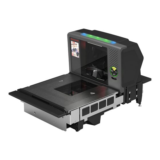
Page 17: Features Of The Stratos Bioptic
Features of the Stratos Bioptic LED Indicators Vertical Scanning Window Horizontal Scanning Window Platter Audible and Visual Indicators The Stratos bioptic provides audible tones and visual indicators that indicate the status of the unit. See Input/Output Settings beginning on page 4-1 to change any of these settings. The following table lists the default audible and visual indica- tions. -
Page 18: Push Button Functionality
LEDs (Continued) Sound Indication Green, Red, Yellow Flash Auxiliary Scanner Beep Auxiliary Scanner Configuration Green, Red, Yellow Flash With or without Beep Scale Calibration Red Flash Razz Error Event - Minor (See Troubleshooting a Stratos Bioptic Scanner, beginning on page 15-1) Red Flash, then Continuous Razz... -
Page 19: Lcd Diagnostic Display
F1 Programmable Functions Press this button once quickly to input a number of repeat scans. For example, if there are 6 cans, the cashier would scan the first can, then push the F1 button 5 times quickly to indicate 5 more repeats of that scan. Press and hold the F1 button for 5 seconds to deactivate an EAS tag. - Page 20 1 - 6...
-
Page 21: Chapter 2 - Installation
Installation Installation Diagrams Stratos 2751 Product Dimensions 7 in. 178mm 4 in. 101.4mm 14 in. 11.5 in. 353mm 292mm 2 - 1... -
Page 22: Stratos 2751 Installation Dimensions
13.228 in. .299 in. 336mm 7.58mm 10.984 in. 9.606 in. 244mm 279mm 4.803 in. 5.492 in. 122mm 139.5mm Bottom View Note: “L” brackets and other counter mounting hardware are not included with the Stratos 2700. 2 - 2... -
Page 23: Stratos 2752 Product Dimensions
Stratos 2752 Product Dimensions Stratos 2752 without scale: 7 in. 178mm 4 in. 101.4mm 15.7 in. 11.5 in. 399mm 292mm Stratos 2752 with scale: 7 in. 178mm 4 in. 101.4mm 15.7 in. 399mm 2 - 3... -
Page 24: Stratos 2752 Installation Dimensions
13.228 in. .299 in. 336mm 7.58mm 9.606 in. 10.984 in. 244mm 279mm 4.803 in. 5.492 in. 122mm 139.5mm Bottom View Note: “L” brackets and other counter mounting hardware are not included with the Stratos 2700. 2 - 4... -
Page 25: Stratos 2753 Product Dimensions
Stratos 2753 Product Dimensions Stratos 2753 without scale: 7 in. 178mm .3 in. 6.8mm 4 in. 101.4mm 4 in. 101.4mm 1.5 in. 16.4 in. 2.1 in. 38mm 417.5mm 52.5mm 11.5 in. 292mm 20 in. 508mm Stratos 2753 with scale: 7 in. .27 in. -
Page 26: Stratos 2753 2 Point Installation Dimensions
2 “L” brackets, Keep connector areas maximum length 11.25 in. (286mm) each, free from obstructions may be used instead of a routed edge. Note: “L” brackets and other counter mounting hardware are not included with the Stratos 2700. 2 - 6... -
Page 27: Stratos 2753 3 Point Installation Dimensions
2 “L” brackets, maximum length 11.25 in. (286mm) each, may be used instead of a routed edge. Note: “L” brackets and other counter mounting hardware are not included with the Stratos 2700. 2 - 7... -
Page 28: Stratos 2753 Bottom View
Stratos 2753 Bottom View 13.228 in. .299 in. 336mm 7.58mm 9.606 in. 10.984 in. 244mm 279mm 4.803 in. 5.492 in. 122mm 139.5mm Bottom View Installing the Stratos Bioptic Step 1. Shut down the POS system. Step 2. Connect the appropriate cables from the host system and auxiliaries to the ports on the 2700. Device Ports Left Side Ports: Camera Video In... -
Page 29: Placing The Stratos Bioptic In The Check Stand
Step 3. Use cable ties to secure the cables to the sides so they won’t interfere with installation. Note: Cable ties are not included with the Stratos 2700. Placing the Stratos Bioptic in the Check Stand Pull up the lift handle located in front of the horizontal window. Use this lift handle with one hand and grasp the 2700 under- neath the vertical display with the other hand. - Page 30 Carefully lower the 2700 into the check stand cutout. Step 4. Route the cables through the check stand cutout to the POS terminal. Note: “L” brackets and other counter mounting hardware are not included with the Stratos 2700. 2 - 10...
-
Page 31: Place The Platter
Place the Platter Place the platter in position over the horizontal window. WARNING: Do not attempt to adjust the screws that support the platter. Any attempt to do so may throw the scale out of calibration. Adjust the Height Make sure the platter is at the correct height and completely level. The front edge of the platter should be flush with the check stand. -
Page 32: Leveling
Remove the platter and make sure the scanner is level both with and without the platter installed. For installations that do not have hanging ledges, adjust the leveling feet at the bottom 4 corners of the scanner until the platter is at the correct height. -
Page 33: Pole Display (If Included)
If the scale is not level, it may fall out of calibration and cannot be used. You must level it in order for it to perform properly. Once the 2700 is at the correct height and level, lock down the leveling screws with the bolt at the bottom. Pole Display (if included) Step 1. -
Page 34: Connecting Eas
The images from the video camera are shown in the upper left corner of the scanner’s vertical tower. Connecting EAS Checkpoint EAS Antenna Port Sensormatic Antenna Connectors Checkpoint® When connecting to a Checkpoint EAS system, connect the Checkpoint EAS interlock cable (if required) to the EAS inter- lock port on the left side of the 2700 (see Device Ports on page 2-8). - Page 35 If using a USB Plus Power connection to the host (12V), match the turquoise cable connector to the turquoise receptor on the 2700. Step 3. Connect the other end of the interface cable to the appropriate communication port on the host's scale device. Step 4.
- Page 36 2 - 16...
-
Page 37: Introduction
Menu Bar Code Security Settings Honeywell scanners are programmed by scanning menu bar codes or by sending serial commands to the scanner. If you want to restrict the ability to scan menu codes, you can use the Menu Bar Code Security settings. Contact the nearest technical sup-... -
Page 38: Resetting The Custom Defaults
Resetting the Custom Defaults If you want the custom default settings restored to your scanner, scan the Activate Custom Defaults bar code below. This is the recommended default bar code for most users. It resets the scanner to the custom default settings. If there are no custom defaults, it will reset the scanner to the factory default settings. -
Page 39: Usb Interface
USB Interface USB PC or Macintosh Keyboard Scan one of the following codes to program the scanner for USB PC Keyboard or USB Macintosh Keyboard. Scanning these codes also adds a CR suffix. USB Keyboard (Mac) USB Japanese Keyboard (PC) USB HID Scan the following code to program the scanner for USB HID bar code scanners. -
Page 40: Usb Serial Commands
Scan the following code to program the scanner to emulate a regular RS232-based COM Port. If you are using a Mic- rosoft® Windows® PC, you will need to download a driver from the Honeywell website (www.honeywellaidc.com). The driver will use the next available COM Port number. Apple® Macintosh computers recognize the scanner as a USB CDC class device and automatically use a class driver. -
Page 41: Usb Host Power
CTS/RTS Emulation CTS/RTS Emulation On * CTS/RTS Emulation Off ACK/NAK Mode ACK/NAK Mode On * ACK/NAK Mode Off USB Host Power When using host power for a USB interface, you may use the following settings to conserve power: Scan No Power Management if the scanner is self-powered. Scan Reduced Motor Speed During Power On if the scanner is being powered by the USB connection from the host. -
Page 42: Host System Plug And Play Codes
Motor/Beeper Power Save Combined Power Save Modes Host System Plug and Play Codes RS485 Scan one of the following “Plug and Play” codes to program the scanner for an IBM POS terminal interface at address 4B. Note: After scanning one of these codes, you must power cycle the cash register. IBM Port 5B Interface IBM Port 9B HHBCR-1 Interface... -
Page 43: Ibm 46Xx - Scanner Only
**Suffixes programmed for Code 128 with IBM 4683 Port 9 HHBCR-2 Interface IBM 46XX - Scanner Only The following bar code sets the scanner for IBM 46XX RS485 emulation, scanner-only protocol defaults. IBM 46XX - Scanner Only IBM Port 17 Interface - Scanner Only The following bar code forces the Stratos bioptic to operate as an IBM tabletop scanner when connected via a single RS485 cable at address 4A. -
Page 44: Usb - Ibm Surepos
USB - IBM SurePos Scan one of the following “Plug and Play” codes to program the scanner for an IBM SurePos (USB handheld scanner) or IBM SurePos (USB tabletop scanner) interface. Note: After scanning one of these codes, you must power cycle the cash register. USB IBM SurePos (USB Handheld Scanner) Interface... -
Page 45: Verifone ® Ruby Terminal Default Settings
® Verifone Ruby Terminal Default Settings Scan the following bar code to program the scanner for a Verifone Ruby terminal. This bar code sets the baud rate to 1200 bps and the data format to 8 data bits, no parity bit, 1 stop bit. It also adds a line feed (LF) suffix and programs the following prefixes for each symbology: Symbology Prefix... -
Page 46: Wincor Nixdorf Beetle™ Terminal Default Settings
Wincor Nixdorf Beetle™ Terminal Default Settings Scan the following bar code to configure the scanner for a Wincor Nixdorf Beetle terminal. The following prefixes are pro- grammed for each symbology: Wincor Nixdorf Beetle Settings Symbology Prefix Symbology Prefix Code 128 EAN-13 Code 93 GS1-128... - Page 47 Keyboard Countries (Continued) Belarus Belgium Bosnia Brazil Brazil (MS) Bulgaria (Cyrillic) Bulgaria (Latin) Canada (French legacy) Canada (French) 3 - 11...
- Page 48 Keyboard Countries (Continued) Canada (Multilingual) China Croatia Czech Czech (Programmers) Czech (QWERTY) Czech (QWERTZ) Denmark Dutch (Netherlands) 3 - 12...
- Page 49 Keyboard Countries (Continued) Estonia Faroese Finland France Gaelic Germany Greek Greek (220 Latin) Greek (220) 3 - 13...
- Page 50 Keyboard Countries (Continued) Greek (319 Latin) Greek (319) Greek (Latin) Greek (MS) Greek (Polytonic) Hebrew Hungarian (101 key) Hungary Iceland 3 - 14...
- Page 51 Keyboard Countries (Continued) Irish Italian (142) Italy Japan ASCII Kazakh Korea Kyrgyz (Cyrillic) Latin America Latvia 3 - 15...
- Page 52 Keyboard Countries (Continued) Latvia (QWERTY) Lithuania Lithuania (IBM) Macedonia Malta Mongolian (Cyrillic) Norway Poland Polish (214) 3 - 16...
- Page 53 Keyboard Countries (Continued) Polish (Programmers) Portugal Romania Russia Russian (MS) Russian (Typewriter) Serbia (Cyrillic) 3 - 17...
- Page 54 Keyboard Countries (Continued) Serbia (Latin) Slovakia Slovakia (QWERTY) Slovakia (QWERTZ) Slovenia Spain Spanish variation Sweden 3 - 18...
- Page 55 Keyboard Countries (Continued) Switzerland (French) Switzerland (German) Tatar Thailand Turkey F Turkey Q Ukrainian United Kingdom United States (Dvorak) 3 - 19...
-
Page 56: Keyboard Style
Keyboard Countries (Continued) United States (Dvorak left) United Stated (Dvorak right) United States (International) Uzbek (Cyrillic) Vietnam Keyboard Style This programs keyboard styles, such as Caps Lock and Shift Lock. If you have used Keyboard Conversion settings, they will override any of the following Keyboard Style settings. Default = Regular. Regular is used when you normally have the Caps Lock key off. -
Page 57: Keyboard Conversion
Shift Lock is used when you normally have the Shift Lock key on (not common to U.S. keyboards). Shift Lock Automatic Caps Lock is used if you change the Caps Lock key on and off. The software tracks and reflects if you have Caps Lock on or off. -
Page 58: Keyboard Modifiers
Convert All Characters to Upper Case Convert All Characters to Lower Case Keyboard Modifiers This modifies special keyboard features, such as CTRL+ ASCII codes and Turbo Mode. Turbo Mode. Control + X (Control + ASCII) Mode On: The scanner sends key combinations for ASCII control characters for values 00-1F. Windows is the preferred mode. - Page 59 Numeric Keypad Mode: Sends numeric characters as if entered from a numeric keypad. Default = Off. Numeric Keypad Mode On * Numeric Keypad Mode Off 3 - 23...
-
Page 60: Rs232 Baud Rate
RS232 Baud Rate Baud Rate sends the data from the scanner to the terminal at the specified rate. The host terminal must be set for the same baud rate as the scanner. Default = 9600. 1200 2400 4800 * 9600 19200 38400 3 - 24... -
Page 61: Rs232 Word Length: Data Bits, Stop Bits, And Parity
57,600 115,200 RS232 Word Length: Data Bits, Stop Bits, and Parity Data Bits sets the word length at 7 or 8 bits of data per character. If an application requires only ASCII Hex characters 0 through 7F decimal (text, digits, and punctuation), select 7 data bits. For applications that require use of the full ASCII set, select 8 data bits per character. - Page 62 7 Data, 2 Stop, Parity None 7 Data, 2 Stop Parity Even 7 Data, 2 Stop, Parity Odd 7 Data, 2 Stop, Parity Space 7 Data, 2 Stop Parity M * 8 Data, 1 Stop, Parity None 8 Data, 1 Stop, Parity Even 8 Data, 1 Stop, Parity Odd 8 Data, 1 Stop, Parity Space 3 - 26...
-
Page 63: Rs232 Receiver Timeout
8 Data, 1 Stop, Parity M RS232 Receiver Timeout The unit stays awake to receive data until the RS232 Receiver Timeout expires. A bar code read resets the timeout. When an RS232 receiver is sleeping, a character may be sent to wake up the receiver and reset the timeout. A transaction on the CTS line will also wake up the receiver. - Page 64 RTS/CTS Off, RTS Inactive Flow Control, No Timeout Character-Based Flow Control, No Timeout Two-Direction Flow Control Flow Control with Timeout Character-Based Flow Control with Timeout CTS-Based Flow Control, No Timeout RTS On No RTS if CTS is On 3 - 28...
-
Page 65: Rs232 Timeout
RS232 Timeout When using Flow Control with Timeout, you must program the length of the delay you want to wait for CTS from the host. Set the length (in milliseconds) for a timeout by scanning the bar code below, then setting the timeout (from 1-65535 milli- seconds) by scanning digits from the inside back cover, then scanning Save. -
Page 66: Ack/Nak
ACK/NAK After transmitting data, the scanner waits for an ACK character (hex 06) or a NAK character (hex 15) response from the host. If ACK is received, the communications cycle is completed and the scanner looks for more bar codes. If NAK is received, the last set of bar code data is retransmitted and the scanner waits for ACK/NAK again. -
Page 67: Nak Retries
Communication Timeout Beeper This selection programs the scanner to issue an error beep when a communication timeout has occurred. The error beep sound is programmed using Number of Beeps/LED Flashes – Error (page 4-11). Default = On. * On Timeout Retries This setting limits the number of Communication Timeout retries. -
Page 68: Rs232 Defaults
RS232 Defaults If you want the custom RS232 default settings restored to your scanner, scan the RS232 Defaults bar code below. This resets the scanner to the custom default settings (see Setting Custom Defaults on page 3-1). If there are no custom defaults, it will reset the scanner to the factory default settings. - Page 69 NCR Scanner Scale Mode Scan the NCR Scanner Scale Mode On bar code to select the NCR scanner/scale message format. (For more infor- mation, refer to the NCR Scanner/Scale Programmer’s Guide.) Default = NCR Scanner Scale Mode Off. * NCR Scanner Scale Mode Off NCR Scanner Scale Mode On NCR Scanner Scale Acknowledgment After the scanner receives a command, the host may require a scanner/scale acknowledgment from the scanner.
-
Page 70: Block Check Character
Block Check Character When this selection is set to Transmit, the NCR Block Check Character (BCC) is expected with incoming messages and transmitted with outgoing messages. Default = Transmit. * Transmit Don’t Transmit NCR Prefix This selection allows you to program an NCR-specific prefix. Refer to the ASCII Conversion Chart (Code Page 1252) page A-3 to find the hex equivalent for the characters you want for the NCR prefix (typically, 02 for STX). -
Page 71: Do Not Wait For Ncr Weight
* Off NCR NOF (Not-on-File) Number of Beeps When using NCR NOF (Not-on-File) Error, set the number of beeps or error tones, from 1 to 7, the scanner emits when it receives an NOF from the POS system. Default = 1. NCR Number of Beeps Do Not Wait for NCR Weight A get weight command waits until either a weight is ready or the command is canceled. - Page 72 Timeout When using NCR Weight Timeout, you must program the length of the delay you want to wait for a weight from the scale. Set the length (in milliseconds) for a timeout by scanning the bar code below, then setting the timeout (from 1- 65535 milliseconds) by scanning digits from the Programming Chart, then scanning Save.
-
Page 73: Chapter 4 - Input/Output Settings
Input/Output Settings Power Up Settings Wake Activation When Wake Activation Off is selected, the Sound button can be used to wake the scanner. When Wake Activation On is selected, the scanner will wake when it senses activity, such as a cashier walking into the space where the scanner is located. - Page 74 Default = Hibernate Mode. Sleep Mode * Hibernate Mode Power Save Mode Timeout Use this selection to set a timeout (in seconds) for the scanner when using Power Save Mode. When this time has elapsed with no activity, the scanner will enter the Power Save Mode selected. After scanning the Power Save Mode Timeout bar code, set the timeout duration (from 0-65535 seconds) by scanning digits on the Programming Chart inside the back cover, then scanning Save.
- Page 75 * Sleep - Lasers Off Idle - Lasers Blinking Sleep - Lasers Blinking Motor Idle/Sleep State These selections program the motor to Off or On when the scanner is in idle mode or in sleep mode. Default = Off. Idle - Motor On * Idle - Motor Off Sleep - Motor On * Sleep - Motor Off...
-
Page 76: Power Up Beeper
Power Up Beeper The scanner can be programmed to beep when it’s powered up. Scan the Off bar code(s) if you don’t want a power up beep. Default = Power Up Beeper On. Power Up Beeper Off * Power Up Beeper On Button Controls Scale Zero F1 Programmable... -
Page 77: Volume Adjustment
Last Scan Repeat When Last Scan Repeat On is set, the cashier can press the F1 button quickly to input a number of repeat scans. For example, if there are 6 identical cans, the cashier would scan the first can, then push the F1 button 5 times quickly to indicate 5 more repeats of that scan. -
Page 78: Sleep Mode
Sound Lock When Sound Lock is set to On, a user cannot turn off the beeper using the Sound button. Pressing the Sound button only scrolls through the volume settings for the scanner’s beeper, but will not allow the sound to be turned off. When Sound Lock is set to Off, the Sound button can be used to turn off the beeper. -
Page 79: Image Capture Button
Error Condition When Error Condition On is set, the cashier can push the Sound button to clear errors (visuals, beeps, and notifica- tions). When Error Condition Off is set, visible and audible error conditions remain. Default = Error Condition On. Error Condition Off * Error Condition On Image Capture Button... -
Page 80: Beep On Bel Character
Programming Chart inside the back cover, then scanning Save. Default = 50. JPEG Image Quality Beep on BEL Character You may wish to force the scanner to beep upon a command sent from the host. If you scan the Beep on BEL On bar code below, the scanner will beep every time a BEL character is received from the host. -
Page 81: Beeper - Transmit Order
Beeper - Transmit Order The beeper transmit order determines when the good read beep occurs. The scanner can be set to emit the good read beep either before or after data transmission. Default = Before Transmission. * Before Transmission After Transmission Beeper Volume –... -
Page 82: Beeper Duration - Good Read
Tone 3 Tone 4 Tone 5 Tone 6 Tone 7 Tone 8 Beeper Duration – Good Read The beeper duration codes modify the length of the beep the scanner emits on a good read. Default = Normal. * Normal Beep Short Beep Number of Beeps –... -
Page 83: Beep On Eas Deactivation
Programming Chart inside the back cover of this manual. Default = 1. Number of Good Read Beeps/LED Flashes Beep on EAS Deactivation After a good read, the beeper will beep quickly (chirp) upon EAS deactivation when Beep on EAS Deactivation is set to On. -
Page 84: Led Settings
Save bar code on the Programming Chart inside the back cover of this manual. Default = 1. Number of Error Beeps/LED Flashes LED Settings Disabled Scanner LED Flash When the scanner is disabled by the POS system, the LEDs can be set to flash by scanning LED Flash On. If you do not want the LEDs to flash, scan LED Flash Off. -
Page 85: User-Specified Reread Delay
Long (1000 ms) Extra Long (2000 ms) User-Specified Reread Delay If you want to set your own length for the reread delay, scan the bar code below, then set the delay (from 0-30,000 millisec- onds) by scanning digits from the inside back cover, then scanning Save. User-Specified Reread Delay 2D Reread Delay Sometimes 2D bar codes can take longer to read than other bar codes. -
Page 86: Same Symbol Test
Long (3000ms) Extra Long (4000ms) Same Symbol Test When Same Symbol Test On is scanned, the current bar code must be 1 character different from the previous bar code in order to be read. When Same Symbol Test Off is scanned, the bar codes must be 25% different to be read. Default = Same Symbol Test Off. -
Page 87: Character Activation Mode
Character Activation Mode You may use a character sent from the host to trigger the scanner to begin scanning. When the activation character is received, the scanner continues scanning until either the Character Activation Laser Timeout (page 4-16), the deactivation character is received (see Deactivation Character on page 4-16), or a bar code is transmitted. -
Page 88: Character Activation Laser Timeout
Character Activation Laser Timeout You can set a timeout for the length of time the laser remains on and attempting to decode bar codes when using Character Activation Mode. Set the length (in milliseconds) for a timeout by scanning the following bar code, then setting the timeout (from 1-65535 milliseconds) by scanning digits from the Programming Chart inside the back cover of this manual, then... -
Page 89: Output Sequence Editor
Output Sequence Editor This programming selection allows you to program the scanner to output data (when scanning more than one symbol) in whatever order your application requires, regardless of the order in which the bar codes are scanned. Reading the Default Sequence symbol programs the scanner to the Universal values, shown below. -
Page 90: Output Sequence Editor
start character match for Code 39, 41h = “A” termination string for first code code identifier for Code 128 9999 code length that must match for Code 128, 9999 = all lengths start character match for Code 128, 42h = “B” termination string for second code code identifier for Code 93 9999... -
Page 91: Sequence Match Beeper
cover of this manual, then scanning Save. Default = 5000 msec. Sequence Timeout Sequence Match Beeper By default, the scanner beeps when a sequence match is found. If you want the scanner to remain silent, scan the follow- ing Sequence Match Beeper Off bar code. Default = Sequence Match Beeper On. Sequence Match Beeper Off * Sequence Match Beeper On Partial Sequence... -
Page 92: No Read
When the output sequence is Off, the bar code data is output to the host as the scanner decodes it. Default = Off. Required On/Not Required *Off No Read With No Read turned On, the scanner notifies you if a code cannot be read. If using an EZConfig-Scanning Tool Scan Data Window (see page 12-2), an “NR”... -
Page 93: Chapter 5 - Programming An Auxiliary Scanner
Scanner to Bioptic Communication The following settings are used to set up communication between Honeywell scanners and bioptic scanners. Note: The scanner’s baud rate must be set to 38400 and the RS232 Timeout must be set to 3000 in order to communicate with a bioptic scanner. -
Page 94: Aux Port Configuration Codes
Aux Port Configuration Codes Honeywell Scanner Aux Port Configuration Scan the following bar code to configure the Stratos bioptic aux port to use a Honeywell auxiliary scanner. Honeywell Aux Scanner Note: See Auxiliary Honeywell Scanner Configuration Codes beginning on page B-1 for common Honeywell hand-held scanner configuration codes. -
Page 95: Aux Scanner D/E Commands
bar code is read with the aux scanner. Scan Good Read Beep - Bioptic and Aux Scanner to sound the good read beep from both the Stratos bioptic and the auxiliary scanner when the bar code is read with the aux scanner. Default = Good Read Beep - Bioptic and Aux Scanner. - Page 96 5 - 4...
-
Page 97: Chapter 6 - Scale
Scale Programming the Scale Interface RS232 OPOS - Single Cable Scan the following programming codes to set up the scanner/scale using the OPOS drivers when connected via a sin- gle RS232 cable. Baud Rate/Parity sets the baud rate to 9600 bps and the data format to 8 data bits, no parity, 1 stop bit. Single Cable configures the Stratos bioptic for a scale interface. -
Page 98: Rs485
POS Beep on Send Weight Note: This selection should only be used for POS “weight-on-demand” applications. Do not use when the POS continually asks for the weight or incessant beeping will be heard. Scan the Beep on Send Weight code below is you want to hear a beep every time the scanner transmits a stable weight. -
Page 99: Scale Status Bytes
IBM OEM USB Metric (kg) Single Cable Scale Status Bytes Scan one of the following bar codes to set how many scale status bytes to send to the host from the scanner. These selections apply to RS485 and IBM OEM protocols. Default = 3 Bytes. 2 Bytes * 3 Bytes Scale Type... -
Page 100: Scale Calibration
Herbert Dibal Digi Teraoka Avery FX100 Scale Calibration The scale must be calibrated if: • It is a first time installation • The scale cannot be re-zeroed • The calibration verification tests indicate errors • There is a change in the units of measure (i.e., from pounds to kilograms) •... -
Page 101: Scale Calibration
5. Wait 5 minutes up to 30 minutes after power up before proceeding. If the unit has been subjected to cold, it may take longer to get to room temperature. 6. Place the 30.0 lb. weights or the 15 kg weights on the center of the scale platter. Allow the weight to settle. 7. - Page 102 Step 1. Press the Zero key on the remote display several times until Grp 2 Step1 is displayed. Grp 2 Step 1 Step 2. Either display will initially display x = NO. Press the Tare key to change this to YES: 21 YES Step 3.
-
Page 103: Scale Calibration Without Remote Display
Step 10. After 3 to 5 seconds of inactivity, press the Zero key to accept and begin taking the zero capacity calibration reading. If the scale is unable to capture a stable reading it will not store any value and will advance to the next step. - Page 104 Step 1. Use a thin rod or straightened paper clip to push down through the exposed pinhole and depress the calibration switch. A scale beep sounds. The scale is now in service mode. Step 2. Use the vertical window to scan a bar code below to calibrate the scale. The scanner beeps once as the scale enters calibration mode and the calibration utility starts.
-
Page 105: Scale Calibration With Push Buttons
Step 6. Remove the full capacity weight from the scale platter. The green LED blinks 5 times. Wait at least 3 seconds for scale stability, then press the Sound button once. There is a short delay followed by 5 short beeps that indicates that the return zero load value has been stored. -
Page 106: Calibration Verification
Step 6. Press the F1 button to activate your selection. The LCD display shows SCALE CALIBRATE – WAIT SCALE RSP for a few seconds, then it changes to Step 1 – Platter Empty, VOL BTN = Advance. The top LED bar on the scanner flashes once every few seconds. -
Page 107: Shift Test
6. Remove all the weight from the scale platter and verify the display reads: 0.00 lbs 0.00kg Shift Test Shift Test Zones 1. Ensure there is no load on the scale platter and verify the remote display reads: 0.00 lbs 0.00kg 2. -
Page 108: Return To Zero Test
7.495 and 7.505kg 4. Remove another 15 lbs. or 5kg from the platter and center the remaining weight. Verify the remote display reads: 5.0 lbs 2.5kg 5. Remove all the weight from the platter and verify the display reads: 0.00 lbs 0.00kg Return to Zero Test Ensure there is no load on the scale platter and verify the remote display reads:... - Page 109 3. Thread the wires through the mandrel, the security plate tab, and the bolt head. 4. Plug the mandrel into the mandrel cover to secure the wire. 5. Reinstall the platter. Note: Recheck the scale zero setting after installing the seals to ensure scale is at zero. If the scale is calibrated without the cover and wire seal, that weight could affect the calibration.
- Page 110 6 - 14...
-
Page 111: Chapter 7 - Data Editing
Data Editing Prefix/Suffix Overview When a bar code is scanned, additional information is sent to the host computer along with the bar code data. This group of bar code data and additional, user-defined data is called a “message string.” The selections in this section are used to build the user-defined data into the message string. -
Page 112: To Clear One Or All Prefixes Or Suffixes
Example: Add a Tab Suffix to All Symbologies Step 1. Scan Add Suffix. Step 2. Scan 9, 9 from the Programming Chart inside the back cover of this manual to apply this suffix to all symbologies. Step 3. Scan 0, 9 from the Programming Chart inside the back cover of this manual. -
Page 113: Suffix Selections
Suffix Selections Add Suffix Clear One Suffix Clear All Suffixes Cash Register Code IDs In order to work properly, some POS registers require that certain Code IDs are sent with all bar codes. Scan the appropriate bar code below to enable the Code ID set required. If you scan more than one of the codes below, the Code ID set for only the last selection is enabled. -
Page 114: Function Code Transmit
Sanyo TEC 711 TEC MA 1530 Wincor Nixdorf Wincor Nixdorf Beetle Function Code Transmit When this selection is enabled and function codes are contained within the scanned data, the scanner transmits the function code to the terminal. Charts of these function codes are provided in Supported Interface Keys starting on page... -
Page 115: Intercharacter, Interfunction, And Intermessage Delays
Scan the following bar code to set the communication check character type. Default = None. * None LRC Starts on 1st Character LRC Starts on 2nd Character Intercharacter, Interfunction, and Intermessage Delays Some terminals drop information (characters) if data comes through too quickly. Intercharacter, interfunction, and intermessage delays slow the transmission of data, increasing data integrity. -
Page 116: Interfunction Delay
Next, scan the Character to Trigger Delay bar code, then the 2-digit hex value for the ASCII character that will trigger the delay ASCII Conversion Chart (Code Page 1252), beginning on page A-3. Delay Length Character to Trigger Delay To remove this delay, scan the Delay Length bar code, and set the number of delays to 0. Scan the Save bar code using Programming Chart inside the back cover of this manual. -
Page 117: Chapter 8 - Data Formatting
Data Formatting Data Format Editor Introduction You may use the Data Format Editor to change the scanner’s output. For example, you can use the Data Format Editor to insert characters at certain points in bar code data as it is scanned. The selections in the following pages are used only if you wish to alter the output. -
Page 118: Other Programming Selections
Step 5. Length Specify what length (up to 9999 characters) of data will be acceptable for this symbology. Scan the four digit data length from the Programming Chart inside the back cover of this manual. (Note: 50 characters is entered as 0050. Note: 9999 indicates all lengths. -
Page 119: Terminal Id Table
Terminal ID Table Terminal Model(s) Terminal ID PC keyboard (HID) Mac Keyboard PC Keyboard (Japanese) Serial (COM driver required) HID POS USB SurePOS Handheld USB SurePOS Tabletop IBM USB POS Tabletop Scanner/Scale (SurePOS) Serial RS232 TTL RS232 True RS485 (IBM-HHBCR 1+2, 46xx) IBM Tabletop Scanner/Scale (SurePOS) Keyboard PS2 compatibles... - Page 120 0D is the hex value for a CR The data is output as: 1234567890 ABCDEFGHIJ <CR> Send all characters up to a particular character F3 Include in the output message all characters from the input message, starting with the character at the current cursor position and continuing to, but not including, the search character “ss,”...
- Page 121 The data is output as: 1234567890**ABCDEFGHIJ <CR> Insert symbology name B3 Insert the name of the bar code’s symbology in the output message, without moving the cursor. Only symbologies with a Honeywell ID are included (see Symbology Charts on page A-1). Refer to the ASCII Conversion Chart (Code Page 1252), beginning on page A-3 for decimal, hex and character codes.
-
Page 122: Move Commands
Send the symbology name and length before the bar code data from the bar code above. Break up these insertions with spaces. End with a carriage return. Command string: B3F42001B4F42001F10D B3 is the “Insert symbology name” command F4 is the “Insert a character multiple times” command 20 is the hex value for a space 01 is the number of times the space character is sent B4 is the “Insert bar code length”... -
Page 123: Search Commands
F5 is the “Move the cursor forward a number of characters” command 03 is the number of characters to move the cursor F1 is the “Send all characters” command 0D is the hex value for a CR The data is output as: 4567890ABCDEFGHIJ <CR>... - Page 124 The data is output as: DEFGHIJ <CR> Search backward for a character F9 Search the input message backward for “xx” character from the current cursor position, leaving the cursor pointing to the “xx” character. Syntax = F9xx where xx stands for the search character’s hex value for its ASCII code. Refer to the ASCII Conversion Chart (Code Page 1252), beginning on page A-3 for decimal, hex and character codes.
-
Page 125: Miscellaneous Commands
F1 is the “Send all characters” command 0D is the hex value for a CR The data is output as: 37692 <CR> Search backward for a non-matching character E7 Search the input message backward for the first non-“xx” character from the current cursor position, leaving the cursor pointing to the non-“xx”... - Page 126 02 is the total count of characters to be replaced, plus the replacement characters (0 is replaced by CR, so total char- acters = 2) 30 is the hex value for 0 0D is the hex value for a CR (the character that will replace the 0) F1 is the “Send all characters”...
-
Page 127: Data Formatter
F1 is the “Send all characters” command 0D is the hex value for a CR If this bar code is read, the format fails. If this bar code is read: the data is output as: AB1234 <CR> Insert a delay EF Inserts a delay of up to 49,995 milliseconds (in multiples of 5), starting from the current cursor position. -
Page 128: Data Format Non-Match Error Tone
Choose one of the following options. Default = Data Formatter On, Not Required, Keep Prefix/Suffix. * Data Formatter On, Not Required, Keep Prefix/Suffix Data Formatter On, Not Required, Drop Prefix/Suffix Data Format Required, Keep Prefix/Suffix Data Format Required, Drop Prefix/Suffix Data Format Non-Match Error Tone When a bar code is encountered that doesn’t match your required data format, the scanner normally generates an error tone. -
Page 129: Primary/Alternate Data Formats
Primary/Alternate Data Formats You can save up to four data formats, and switch between these formats. Your primary data format is saved under 0. Your other three formats are saved under 1, 2, and 3. To set your device to use one of these formats, scan one of the bar codes below. Primary Data Format Data Format 1 Data Format 2... - Page 130 8 - 14...
-
Page 131: All Symbologies
Symbologies This programming section contains the following menu selections. Refer to Chapter 13 for settings and defaults. • All Symbologies • GS1-128 • Aztec Code • In-Store Printed Bar Codes • Chinese Sensible (Han Xin) Code • Interleaved 2 of 5 •... -
Page 132: Codabar
EXAMPLE: Decode only those bar codes with a count of 9-20 characters. Min. length = 09Max. length = 20 EXAMPLE: Decode only those bar codes with a count of 15 characters. Min. length = 15Max. length = 15 For a value other than the minimum and maximum message length defaults, scan the bar codes included in the explanation of the symbology, then scan the digit value of the message length and Save bar codes on the Programming Chart inside the back... -
Page 133: Codabar Concatenation
When Check Character is set to Validate, but Don’t Transmit, the unit will only read Codabar bar codes printed with a check character, but will not transmit the check character with the scanned data. * No Check Character Validate Modulo 16, but Don’t Transmit Validate Modulo 16 and Transmit... -
Page 134: Codabar Message Length
Codabar Redundancy If you are encountering errors when reading Codabar bar codes, you may want to adjust the redundancy count. Redun- dancy adjusts the number of times a bar code is decoded before transmission, which may reduce the number of errors. Note that the higher the redundancy count, the longer it will take to decode the bar code. -
Page 135: Code 39
Code 39 Default All Code 39 Settings Code 39 On/Off * Off Code 39 Start/Stop Characters Start/Stop characters identify the leading and trailing ends of the bar code. You may either transmit, or not transmit Start/ Stop characters. Default = Don’t Transmit. Transmit * Don’t Transmit Code 39 Check Character... -
Page 136: Code 32 Pharmaceutical (Paraf)
Validate, but Don’t Transmit Validate and Transmit Code 39 Message Length Scan the bar codes below to change the message length. Refer to Message Length Description (page 9-1) for additional information. Minimum and Maximum lengths = 0-80. Minimum Default = 3, Maximum Default = 80. Minimum Message Length Maximum Message Length Code 39 Redundancy... -
Page 137: Full Ascii
* Off Full ASCII If Full ASCII Code 39 decoding is enabled, certain character pairs within the bar code symbol will be interpreted as a single character. For example: $V will be decoded as the ASCII character SYN, and /C will be decoded as the ASCII character #. Default = Off. -
Page 138: Interleaved 2 Of 5
Programming Chart on the inside the back cover of this manual. The data characters should then appear properly. Code 39 Code Page Interleaved 2 of 5 Default All Interleaved 2 of 5 Settings Interleaved 2 of 5 On/Off * Off NULL Characters Interleaved 2 of 5 requires an even number of characters. -
Page 139: Interleaved 2 Of 5 Message Length
When Check Digit is set to Validate and Transmit, the scanner only reads Interleaved 2 of 5 bar codes printed with a check digit, and will transmit this digit at the end of the scanned data. Default = No Check Digit. * No Check Digit Validate, but Don’t Transmit Validate and Transmit... -
Page 140: Nec 2 Of 5
NEC 2 of 5 Default All NEC 2 of 5 Settings NEC 2 of 5 On/Off * Off Check Digit No Check Digit indicates that the scanner reads and transmits bar code data with or without a check digit. When Check Digit is set to Validate, but Don’t Transmit, the unit only reads NEC 2 of 5 bar codes printed with a check digit, but will not transmit the check digit with the scanned data. -
Page 141: Code 93
inside the back cover of this manual. Then scan the Save bar code. Default = 0. NEC 2 of 5 Redundancy NEC 2 of 5 Message Length Scan the bar codes below to change the message length. Refer to Message Length Description (page 9-1) for additional information. -
Page 142: Code 93 Code Page
inside the back cover of this manual. Then scan the Save bar code. Default = 0. Code 93 Redundancy Code 93 Message Length Scan the bar codes below to change the message length. Refer to Message Length Description (page 9-1) for additional information. -
Page 143: Straight 2 Of 5 Industrial (Three-Bar Start/Stop)
Straight 2 of 5 Industrial (three-bar start/stop) Default All Straight 2 of 5 Industrial Settings Straight 2 of 5 Industrial On/Off * Off Straight 2 of 5 Industrial Redundancy If you are encountering errors when reading Straight 2 of 5 Industrial bar codes, you may want to adjust the redundancy count. -
Page 144: Straight 2 Of 5 Iata (Two-Bar Start/Stop)
Straight 2 of 5 IATA (two-bar start/stop) Default All Straight 2 of 5 IATA Settings Straight 2 of 5 IATA On/Off * Off Straight 2 of 5 IATA Redundancy If you are encountering errors when reading Straight 2 of 5 IATA bar codes, you may want to adjust the redundancy count. Redundancy adjusts the number of times a bar code is decoded before transmission, which may reduce the number of errors. -
Page 145: Matrix 2 Of 5
Matrix 2 of 5 Default All Matrix 2 of 5 Settings Matrix 2 of 5 On/Off * Off Check Digit No Check Digit indicates that the scanner reads and transmits bar code data with or without a check digit. When Check Digit is set to Validate, but Don’t Transmit, the unit only reads Matrix 2 of 5 bar codes printed with a check digit, but will not transmit the check digit with the scanned data. -
Page 146: Matrix 2 Of 5 Message Length
Chart inside the back cover of this manual, then scanning Save. Default = 0. Matrix 2 of 5 Redundancy Matrix 2 of 5 Message Length Scan the bar codes below to change the message length. Refer to Message Length Description (page 9-1) for additional information. -
Page 147: Code 11
Code 11 Default All Code 11 Settings Code 11 On/Off * Off Check Digits Required These options set whether 1 or 2 check digits are required with Code 11 bar codes. The check digit data is only transmitted if you program that feature (see Check Digit Validation on page 9-17). - Page 148 Code 11 Redundancy If you are encountering errors when reading Code 11 bar codes, you may want to adjust the redundancy count. Redun- dancy adjusts the number of times a bar code is decoded before transmission, which may reduce the number of errors. Note that the higher the redundancy count, the longer it will take to decode the bar code.
-
Page 149: Code 128
Code 128 Default All Code 128 Settings Code 128 On/Off * On 128 Group Separator Output When Off is selected, group separator characters (FNC 1 characters embedded in the bar code) are not output. If you wish to transmit the FNC1 characters as group separators “GS” (0x1D hex) with your Code 128 bar code output, scan the On bar code. -
Page 150: Code 128 Message Length
Code 128 Message Length Scan the bar codes below to change the message length. Refer to Message Length Description (page 9-1) for additional information. Minimum and Maximum lengths = 0-80. Minimum Default = 3, Maximum Default = 80. Minimum Message Length Maximum Message Length Code 128 Code Page Code pages define the mapping of character codes to characters. -
Page 151: Isbt 128
Concatenation Timeout When searching for bar codes during concatenation, you may wish to set a delay used to find the next bar code. Set the length (in milliseconds) for this delay by scanning the bar code below, then setting the timeout (from 1-65535 milliseconds) by scanning digits from the Programming Chart, then scanning Save. - Page 152 Product Code (003) and Expiration Date (Form 3) Product Code (003) and Expiration Date (Form 4) ISBT 128 Predefined Concatenation Sequences On/Off The following selections allow you to enable or require the Predefined ISBT 128 Concatenation Sequences. If you scan Off, the predefined concatenation sequences are disabled. If you scan the Allow Predefined Sequence code, then the scanner will output only the data combination specified in the predefined concatenation sequence you selected.
- Page 153 The ISBT Index of Data Structures shows that for the Donation Identification Number, the first character is “=” and the sec- ond character can be from A-N; P-Z; 1-9. For this example, use “G.” The Product Code first character is “=” and the second character is “<.”...
- Page 154 If you scan the Require User-Defined Sequence code, the data combination specified in the User-Defined concatenation sequence is required to transmit the data. No data is output unless the sequence is read. Default = Off. * Off Allow User-Defined Sequence Require User-Defined Sequence Content Verification When the On bar code is scanned, the check character values are output along with the bar code data, thus allowing you to...
- Page 155 Flag Digit Conversion Type 3 flag digits are a part of the Donation Identification Number in an ISBT 128 bar code. If you select On, the flag data is converted into a single MOD (37, 2) character and transmitted with the bar code data. Scan Off if you do not want the flag digits transmitted.
-
Page 156: Gs1-128
GS1-128 Default All GS1-128 Settings GS1-128 On/Off * Off GS1-128 Application Identifier Parsing This allows a single GS1-128 bar code to be broken into multiple transmissions based on the presence of application iden- tifiers (AI) embedded in the bar code. To use this feature, first enable 128 Group Separator Output (page 9-19). - Page 157 inside the back cover of this manual. Then scan the Save bar code. Default = 0. GS1-128 Redundancy GS1-128 Message Length Scan the bar codes below to change the message length. Refer to Message Length Description (page 9-1) for additional information.
-
Page 158: Telepen
Telepen Default All Telepen Settings Telepen On/Off * Off Telepen Output Using AIM Telepen Output, the scanner reads symbols with start/stop pattern 1 and decodes them as standard full ASCII (start/stop pattern 1). When Original Telepen Output is selected, the scanner reads symbols with start/stop pattern 1 and decodes them as compressed numeric with optional full ASCII (start/stop pattern 2). -
Page 159: Upc-A
Telepen Message Length Scan the bar codes below to change the message length. Refer to Message Length Description (page 9-1) for additional information. Minimum and Maximum lengths = 1-80. Minimum Default = 3, Maximum Default = 80. Minimum Message Length Maximum Message Length UPC-A Default All UPC-A Settings... - Page 160 UPC-A Number System The numeric system digit of a U.P.C. symbol is normally transmitted at the beginning of the scanned data, but the unit can be programmed so it will not transmit it. Default = On. * On UPC-A Addenda This selection adds 2 or 5 digits to the end of all scanned UPC-A data.
- Page 161 UPC-A Addenda Required When Required is scanned, the scanner will only read UPC-A bar codes that have addenda. You must then turn on a 2 or 5 digit addenda listed on page 9-30. Default = Not Required. Required * Not Required UPC-A Addenda Separator When this feature is on, there is a space between the data from the bar code and the data from the addenda.
-
Page 162: Upc-A/Ean-13
manual. Then scan the Save bar code. Default = 2 for 2-Digit Addenda, 1 for 5-Digit Addenda. 2-Digit Addenda Redundancy 5-Digit Addenda Redundancy UPC-A/EAN-13 with Extended Coupon Code Use the following codes to enable or disable UPC-A and EAN-13 with Extended Coupon Code. When left on the default setting (Off), the scanner treats Coupon Codes and Extended Coupon Codes as single bar codes. -
Page 163: Upc-A Number System 5 Addenda Required
Don’t Require Coupon Code: If you have selected Require Coupon Code, and you want to disable this feature, scan Don’t Require Coupon Code. UPC-A bar codes are transmitted, depending on the setting you are using for UPC-A/EAN- 13 with Extended Coupon Code. -
Page 164: Coupon Gs1 Databar Output
Require Coupon Code Require Coupon Code or 2 Digit Addenda Require Coupon Code or 5 Digit Addenda Require Coupon Code, 2 Digit Addenda, or 5 Digit Addenda Addenda Timeout You can set a time during which the scanner looks for an addenda. If an addenda is not found within this time period, the data can be either transmitted or discarded, based on the setting you are using for UPC-A Number System 4 Addenda Required... -
Page 165: In-Store Printed Bar Codes
GS1 Output On In-Store Printed Bar Codes In-store UPC and EAN bar codes are sometimes haphazardly printed, resulting in poor quality codes. The decoding of in-store bar codes may need some adjustment to improve read rates. The following settings allow you to make fine adjustments to the way the decoder interprets the bar code data from in-store printed UPC and EAN bar codes. -
Page 166: Redundancy
Redundancy Redundancy adjusts the number of times a bar code is decoded before transmission, which may reduce the number of errors. Note that the higher the redundancy count, the longer it will take to decode the bar code. If you are having difficulty reading poor quality in-store bar codes, you may wish to scan a higher Redundancy bar code below to improve the read rate. -
Page 167: Upc-E0
Medium Low * Medium Medium High High UPC-E0 Default All UPC-E Settings UPC-E0 On/Off Most U.P.C. bar codes lead with the 0 number system. To read these codes, use the UPC-E0 On selection. Default = On. * UPC-E0 On UPC-E0 Off UPC-E0 Expand UPC-E Expand expands the UPC-E code to the 12 digit, UPC-A format. - Page 168 * Off UPC-E0 Addenda Required When Required is scanned, the scanner will only read UPC-E bar codes that have addenda. Default = Not Required. Required * Not Required UPC-E0 Addenda Separator When this feature is On, there is a space between the data from the bar code and the data from the addenda. When turned Off, there is no space.
- Page 169 UPC-E0 Number System The numeric system digit of a U.P.C. symbol is normally transmitted at the beginning of the scanned data, but the unit can be programmed so it will not transmit it. To prevent transmission, scan Off. Default = Off. * Off UPC-E0 Addenda This selection adds 2 or 5 digits to the end of all scanned UPC-E data.
- Page 170 inside the back cover of this manual. Then scan the Save bar code. Default = 1. UPC-E0 Redundancy UPC/EAN Addenda Redundancy This programs the number of redundant scans required of a 2 or 5-digit addendum before it is attached to the UPC or EAN bar code and submitted.
-
Page 171: Ean/Jan-13
EAN/JAN-13 Default All EAN/JAN Settings EAN/JAN-13 On/Off * On Convert UPC-A to EAN-13 When UPC-A Converted to EAN-13 is selected, UPC-A bar codes are converted to EAN-13. When Do not Convert UPC-A is selected, UPC-A codes are read as UPC-A. UPC-A Converted to EAN-13 * Do not Convert UPC-A EAN/JAN-13 Check Digit... -
Page 172: Ean-13 Beginning With 2 Addenda Required
EAN/JAN-13 Addenda This selection adds 2 or 5 digits to the end of all scanned EAN/JAN-13 data. Default = Off for both 2 Digit and 5 Digit Addenda. 2 Digit Addenda On * 2 Digit Addenda Off 5 Digit Addenda On * 5 Digit Addenda Off EAN/JAN-13 Addenda Required When Required is scanned, the scanner will only read EAN/JAN-13 bar codes that have addenda. -
Page 173: Ean-13 Beginning With 290 Addenda Required
Don’t Require 2 Digit Addenda: If you have selected Require 2 Digit Addenda, and you want to disable this feature, scan Don’t Require 2 Digit Addenda. EAN-13 bar codes are transmitted, depending on the setting you are using for EAN/ JAN-13 Addenda Required. -
Page 174: Ean-13 Beginning With 414/419 Addenda Required
Default = Don’t Require Addenda. * Don’t Require Addenda Require 2 Digit Addenda Require 5 Digit Addenda Require 2 or 5 Digit Addenda EAN-13 Beginning with 414/419 Addenda Required This setting programs the scanner to require any combination of a 2 digit addenda or a 5 digit addenda on EAN-13 bar codes that begin with a “414”... -
Page 175: Ean-13 Beginning With 434/439 Addenda Required
Require 2 or 5 Digit Addenda EAN-13 Beginning with 434/439 Addenda Required This setting programs the scanner to require any combination of a 2 digit addenda or a 5 digit addenda on EAN-13 bar codes that begin with a “434” or “439.” The following settings can be programmed: Require Addenda: All EAN-13 bar codes that begin with a “434”... -
Page 176: Ean-13 Beginning With 978 Addenda Required
Default = Don’t Require 2 Digit Addenda. * Don’t Require 2 Digit Addenda Require 2 Digit Addenda EAN-13 Beginning with 978 Addenda Required These settings program the scanner to require a 5 digit addenda only on EAN-13 bar codes that begin with “978.” The fol- lowing settings can be programmed: Require 5 Digit Addenda: All EAN-13 bar codes that begin with “978”... - Page 177 Default = Don’t Require 5 Digit Addenda. * Don’t Require 5 Digit Addenda Require 5 Digit Addenda Addenda Timeout You can set a time during which the scanner looks for an addenda. If an addenda is not found within this time period, the data can be either transmitted or discarded, based on the setting you are using for EAN/JAN-13 Addenda Required.
-
Page 178: Isbn Translate
Programming Chart inside the back cover of this manual. Then scan the Save bar code. Default = 0. EAN/JAN-13 Redundancy UPC/EAN Addenda Redundancy This programs the number of redundant scans required of a 2 or 5-digit addendum before it is attached to the UPC or EAN bar code and submitted. -
Page 179: Issn Translate
*Convert to 13-Digit Off ISBN Reformat In normal use, the first two or three digits of an EAN-13 bar code identify the country of origin. The country prefixes are 978 and 979. To reformat ISBN codes so the country prefix is dropped out, scan the Reformat On bar code below. Default = Reformat Off. -
Page 180: Ean/Jan-8
* Reformat Off EAN/JAN-8 Default All EAN/JAN-8 Settings EAN/JAN-8 On/Off * On EAN/JAN-8 Check Digit This selection allows you to specify whether the check digit should be transmitted at the end of the scanned data or not. Default = On. * On EAN/JAN-8 Addenda This selection adds 2 or 5 digits to the end of all scanned EAN/JAN-8 data. - Page 181 * 2 Digit Addenda Off 5 Digit Addenda On * 5 Digit Addenda Off EAN/JAN-8 Addenda Required When Required is scanned, the scanner will only read EAN/JAN-8 bar codes that have addenda. Default = Not Required. Required * Not Required EAN/JAN-8 Addenda Separator When this feature is On, there is a space between the data from the bar code and the data from the addenda.
- Page 182 EAN/JAN-8 Redundancy If you are encountering errors when reading EAN/JAN-8 bar codes, you may want to adjust the redundancy count. Redun- dancy adjusts the number of times a bar code is decoded before transmission, which may reduce the number of errors. Note that the higher the redundancy count, the longer it will take to decode the bar code.
-
Page 183: Msi
Default All MSI Settings MSI On/Off * Off MSI Check Character Different types of check characters are used with MSI bar codes. You can program the scanner to read MSI bar codes with Type 10 check characters. Default = Validate Type 10, but Don’t Transmit. When Check Character is set to Validate Type 10/11 and Transmit, the scanner will only read MSI bar codes printed with the specified type check character(s), and will transmit the character(s) at the end of the scanned data. -
Page 184: Msi Message Length
Validate Type 10 then Type 11 Character, but Don’t Transmit Validate Type 10 then Type 11 Character and Transmit Disable MSI Check Characters MSI Redundancy If you are encountering errors when reading MSI bar codes, you may want to adjust the redundancy count. Redundancy adjusts the number of times a bar code is decoded before transmission, which may reduce the number of errors. -
Page 185: Plessey Code
Plessey Code Default All Plessey Code Settings Plessey Code On/Off * Off Plessey Check Character No Check Character indicates that the scanner reads and transmits bar code data with or without a check character. When Check Character is set to Validate, but Don’t Transmit, the unit only reads Plessey bar codes printed with a check character, but will not transmit the check character with the scanned data. -
Page 186: Plessey Message Length
inside the back cover of this manual. Then scan the Save bar code. Default = 0. Plessey Redundancy Plessey Message Length Scan the bar codes below to change the message length. Refer to Message Length Description (page 9-1) for additional information. -
Page 187: Gs1 Databar Limited
= 0. GS1 DataBar Omnidirectional Redundancy GS1 DataBar Limited Default All GS1 DataBar Limited Settings GS1 DataBar Limited On/Off * On GS1 DataBar Limited Redundancy If you are encountering errors when reading GS1 DataBar Limited bar codes, you may want to adjust the redundancy count. -
Page 188: Gs1 Databar Expanded
GS1 DataBar Expanded Default All GS1 DataBar Expanded Settings GS1 DataBar Expanded On/Off * On Note: Contact Technical Assistance (page 16-1) for help if you have difficulty with GS1 DataBar Expanded bar codes. GS1 DataBar Expanded Redundancy If you are encountering errors when reading GS1 DataBar Expanded bar codes, you may want to adjust the redundancy count. -
Page 189: Coupon Code Settings
Coupon Code Settings GS1 DataBar Expanded Coupons With AI (8110) This selection lets you control reading GS1 DataBar Expanded coupon codes that have an application identifier (AI) of 8110. When On is scanned, GS1 DataBar Expanded coupon codes that have an AI of 8110 are read. When Off is scanned, GS1 DataBar Expanded coupon codes with AI (8110) are not read. -
Page 190: Coupon Gs1 Databar Output
* Off Coupon GS1 DataBar Output If you scan coupons that have both UPC and GS1 DataBar codes, you may wish to scan and output only the data from the GS1 DataBar code. Scan the GS1 Output On code below to scan and output only the GS1 DataBar code data. Default = GS1 Output Off. - Page 191 Framing Framing controls the framing rules for in-store UPC and EAN bar codes. If you are having difficulty reading poor qual- ity in-store bar codes, you may wish to scan the Framing Off bar code below to improve the read rate. Default = Fram- ing Off.
-
Page 192: Trioptic Code
Trioptic Code Note: If you are going to scan Code 32 Pharmaceutical codes (page 9-6), Trioptic Code must be off. Trioptic Code is used for labeling magnetic storage media. * Off Codablock A Default All Codablock A Settings Codablock A On/Off * Off Codablock A Message Length Scan the bar codes below to change the message length. -
Page 193: Codablock F
Codablock F Default All Codablock F Settings Codablock F On/Off * Off Codablock F Message Length Scan the bar codes below to change the message length. Refer to Message Length Description (page 9-1) for additional information. Minimum and Maximum lengths = 1-2048. Minimum Default = 1, Maximum Default = 2048. Minimum Message Length Maximum Message Length 9 - 63... -
Page 194: Pdf417
PDF417 Default All PDF417 Settings PDF417 On/Off * Off PDF417 Message Length Scan the bar codes below to change the message length. Refer to Message Length Description (page 9-1) for additional information. Minimum and Maximum lengths = 1-2750. Minimum Default = 1, Maximum Default = 2750. Minimum Message Length Maximum Message Length MacroPDF417... -
Page 195: Micropdf417
MicroPDF417 Default All MicroPDF417 Settings MicroPDF417 On/Off * Off MicroPDF417 Message Length Scan the bar codes below to change the message length. Refer to Message Length Description (page 9-1) for additional information. Minimum and Maximum lengths = 1-366. Minimum Default = 1, Maximum Default = 366. Minimum Message Length Maximum Message Length GS1 Composite Codes... -
Page 196: Gs1 Composite Code Message Length
* Off UPC/EAN Version Scan the UPC/EAN Version On bar code to decode GS1 Composite symbols that have a U.P.C. or an EAN linear compo- nent. (This does not affect GS1 Composite symbols with a GS1-128 or GS1 linear component.) Default = UPC/EAN Ver- sion Off. -
Page 197: Tcif Linked Code 39 (Tlc39)
If EAN8 to EAN13 Conversion is scanned, all EAN8 bar codes are converted to EAN13 format. 7 Default = GS1 Emulation Off. GS1-128 Emulation GS1 DataBar Emulation GS1 Code Expansion Off EAN8 to EAN13 Conversion * GS1 Emulation Off TCIF Linked Code 39 (TLC39) This code is a composite code since it has a Code 39 linear component and a MicroPDF417 stacked code component. -
Page 198: Qr Code
QR Code Default All QR Code Settings QR Code On/Off This selection applies to both QR Code and Micro QR Code. * Off QR Code Message Length Scan the bar codes below to change the message length. Refer to Message Length Description (page 9-1) for additional information. -
Page 199: Data Matrix
Data Matrix Default All Data Matrix Settings Data Matrix On/Off * On Data Matrix Message Length Scan the bar codes below to change the message length. Refer to Message Length Description (page 9-1) for additional information. Minimum and Maximum lengths = 1-3116. Minimum Default = 1, Maximum Default = 3116. Minimum Message Length Maximum Message Length 9 - 69... -
Page 200: Maxicode
Data Matrix Append This function allows the scanner to append the data from several Data Matrix bar codes together before transmitting them to the host computer. When the scanner encounters an Data Matrix bar code with the append trigger character(s), it buf- fers the number of Data Matrix bar codes determined by information encoded in those bar codes. -
Page 201: Aztec Code
Maximum Message Length Aztec Code Default All Aztec Code Settings Aztec Code On/Off * On Aztec Code Message Length Scan the bar codes below to change the message length. Refer to Message Length Description (page 9-1) for additional information. Minimum and Maximum lengths = 1-3832. Minimum Default = 1, Maximum Default = 3832. Minimum Message Length Maximum Message Length 9 - 71... -
Page 202: Chinese Sensible (Han Xin) Code
Aztec Append This function allows the scanner to append the data from several Aztec bar codes together before transmitting them to the host computer. When the scanner encounters an Aztec bar code with the append trigger character(s), it buffers the number of Aztec bar codes determined by information encoded in those bar codes. - Page 203 Maximum Message Length 9 - 73...
- Page 204 9 - 74...
-
Page 205: Chapter 10 - Eas Settings
EAS Settings EAS Deactivation The Stratos bioptic supports deactivation of Checkpoint and Sensormatic/Tyco EAS tags. The following illustration shows the location of the EAS deactivation area. It is important to pass the entire tag through this area to deactivate the security tag. EAS Deactivation Zone The entire tag must pass through the EAS... -
Page 206: Sensormatic
Sensormatic Detection Ranges 8.5 in (21.5cm) 4 in (10.2cm) Deactivation Ranges 8 in (20.3cm) 4 in (10.2cm) Checkpoint EAS Controller Settings The following switch settings for a Checkpoint Counterpoint IX controller can be used as a starting point, however, these 10 - 2... -
Page 207: Programming The Eas Interface
settings should be tuned according to your particular installation. Using a 2 ft (.61m) cable Part #52-52511 Using a 6 ft (1.83m) cable Part #52-52556 Cable EAS Detection Volume Width Height Depth 2 ft (.61m) #52-52511 11 in. (27.94cm) 6.75 in. (17.15cm) 10 in. -
Page 208: Eas Controller
GPIO Sensormatic RS232 Sensormatic EAS Controller Scan one of the following bar codes to select the EAS system that is attached to the scanner. Default = Off. * Off Checkpoint Systems NEDAP Gateway Security Sensormatic AMB9010 Sensormatic ScanMaxPro 10 - 4... -
Page 209: Eas Interface
EAS Interface Scan one of the following bar codes to select the type of interface the EAS device uses to connect to the scanner. Default = GPIO. * GPIO RS232 EAS Mode of Operation Scan one of the following bar codes to select the EAS mode you wish to use. When Interlocked is selected, EAS tag deactivation is interlocked with bar code scanning and transmission. -
Page 210: Eas Tag Detection
Programming Chart inside the back cover, then scanning Save. Default = 4000 ms, which is 4 seconds. Note: If the EAS tag has not been deactivated in this time period, the operator can deactivate it using the F1 button. EAS Function on page 4-5 to program this functionality. -
Page 211: Chapter 11 - Interface Keys
Interface Keys Keyboard Function Relationships The following Keyboard Function Code, Hex/ASCII Value, and Full ASCII “CTRL”+ relationships apply to all terminals that can be used with the scanner. Refer to page 3-22 enable Control + X mode. Function Code HEX/ASCII Value Full ASCII “CTRL”... - Page 212 Country Codes Denmark Norway Spain 11 - 2...
-
Page 213: Supported Interface Keys
Supported Interface Keys IBM PC/AT and Compatibles, Apple Mac/iMac ASCII USB PC Supported Keys Keyboard Reserved Reserved Enter (KP) Enter/Numpad Enter Cap Lock CAPS ALT make ALT make ALT break ALT break CTRL make CNTRL make CTRL break CNTRL break CR/Enter RETURN Reserved... - Page 214 11 - 4...
-
Page 215: Chapter 12 - Utilities
Utilities To Add a Test Code I.D. Prefix to All Symbologies This selection allows you to turn on transmission of a Code I.D. before the decoded symbology. (See the Symbology Charts, beginning on page A-1) for the single character code that identifies each symbology.) This action first clears all current prefixes, then programs a Code I.D. -
Page 216: Totalfreedom
Note: EZConfig-Scanning requires .NET software. If .NET is not installed on your PC, you will be prompted to install it during the EZConfig-Scanning installation. 1. Access the Honeywell web site at www.honeywellaidc.com 2. Click on the Resources tab. Select Software. -
Page 217: Resetting The Factory Defaults
8. Double click on the Setup.exe file. Follow the screen prompts to install the EZConfig-Scanning program. 9. If you’ve selected the defaults during installation, you can click on Start Menu-All Programs-Honeywell-EZConfig- Scanning. Resetting the Factory Defaults This selection erases all your settings and resets the scanner to the original factory defaults. It also disables all plugins. - Page 218 12 - 4...
-
Page 219: Chapter 13 - Serial Programming Commands
Serial Programming Commands The serial programming commands can be used in place of the programming bar codes. Both the serial commands and the programming bar codes will program the scanner. For complete descriptions and examples of each serial programming com- mand, refer to the corresponding programming bar code in this manual. -
Page 220: Responses
Concatenation of Multiple Commands Multiple commands can be issued within one Prefix/Storage sequence. Only the Tag, SubTag, and Data fields must be repeated for each command in the sequence. If additional commands are to be applied to the same Tag, then the new command sequence is separated with a comma (,) and only the SubTag and Data fields of the additional command are issued. -
Page 221: Menu Commands
Menu Commands Serial Command Setting Selection Page # Indicates a numeric * Indicates default entry Product Default Settings Setting Custom Defaults Set Custom Defaults MNUCDP Save Custom Defaults MNUCDS Resetting the Custom Defaults Activate Custom Defaults DEFALT Resetting the Factory Defaults Remove Custom Defaults DEFOVR 12-3... - Page 222 Serial Command Setting Selection Page # Indicates a numeric * Indicates default entry NCR Host System Scanner Only - Dual Cable PAP953 Verifone Verifone Ruby Terminal PAPRBY Gilbarco Gilbarco Terminal PAPGLB Wincor Nixdorf Wincor Nixdorf Terminal PAPWNX Wincor Nixdorf Beetle Terminal PAPBTL 3-10 Program Keyboard...
- Page 223 Serial Command Setting Selection Page # Indicates a numeric * Indicates default entry Greek (Polytonic) KBDCTY60 3-14 Hebrew KBDCTY12 3-14 Hungarian (101 key) KBDCTY50 3-14 Hungary KBDCTY19 3-14 Iceland KBDCTY75 3-14 Irish KBDCTY73 3-15 Italian (142) KBDCTY56 3-15 Italy KBDCTY5 3-15 Japan ASCII KBDCTY28...
- Page 224 Serial Command Setting Selection Page # Indicates a numeric * Indicates default entry Thailand KBDCTY94 3-19 Turkey F KBDCTY27 3-19 Turkey Q KBDCTY24 3-19 Ukrainian KBDCTY76 3-19 United Kingdom KBDCTY7 3-19 United Stated (Dvorak right) KBDCTY89 3-20 United States (Dvorak left) KBDCTY88 3-20 United States (Dvorak)
- Page 225 Serial Command Setting Selection Page # Indicates a numeric * Indicates default entry Word Length: Data Bits, Stop Bits, and 7 Data, 1 Stop, Parity None 232WRD0 3-25 Parity 7 Data, 1 Stop, Parity Even 232WRD3 3-25 7 Data, 1 Stop, Parity Odd 232WRD6 3-25 7 Data, 1 Stop, Parity Space...
- Page 226 Serial Command Setting Selection Page # Indicates a numeric * Indicates default entry Support BEL/CAN in ACK/NAK BEL/CAN Mode On BELCAN1 3-31 BEL/CAN Mode Off* BELCAN0 3-31 RS232 Defaults 232DFT 3-32 NCR Modifiers NCR ACK *NCR ACK Off NCRACK0 3-32 NCR ACK On NCRACK1 3-32...
- Page 227 Serial Command Setting Selection Page # Indicates a numeric * Indicates default entry Motor Idle/Sleep State Idle - Motor On PWRMS10 *Idle - Motor Off PWRMS11 Sleep - Motor On PWRMS20 *Sleep - Motor Off PWRMS21 Power Up Beeper Power Up Beeper Off BEPPWR0 *Power Up Beeper On BEPPWR1...
- Page 228 Serial Command Setting Selection Page # Indicates a numeric * Indicates default entry Beeper Pitch - Good Read *Tone 1 BEPCUR1 Tone 3 BEPCUR3 Tone 4 BEPCUR4 Tone 5 BEPCUR5 Tone 6 BEPCUR6 Tone 7 BEPCUR7 Tone 8 BEPCUR8 Beeper Duration - Good Read *Normal Beep BEPBIP0 4-10...
- Page 229 ACK/NAK On 232ACK1 *ACK/NAK Off 232ACK0 Communication Timeout Range 0 - 65535ms *2000 232DLK##### Honeywell Scanner Aux Port Configuration Honeywell Aux Scanner AUXDFT Datalogic Magellan Aux Port Configuration Datalogic Magellan Aux Scanner AUXMAG NCR Bioptic Aux Port Configuration NCR Aux Scanner...
- Page 230 Serial Command Setting Selection Page # Indicates a numeric * Indicates default entry RS485 IBM 3rd Generation 46xx, English (lbs) - PAP960 Single Cable IBM 3rd Generation 46xx, Metric (kg) - Single PAP959 Cable IBM OEM USB English (lbs) - Single Cable PAP962 IBM OEM USB Metric (kg) - Single Cable PAP961...
- Page 231 Serial Command Setting Selection Page # Indicates a numeric * Indicates default entry Communication Check Character *None HSTXRC0 LRC Starts on 1st Character HSTXRC1 LRC Starts on 2nd Character HSTXRC2 HSTXRC3 Intercharacter Delay Range 0 - 65535 (1ms increments) DLYCHR## User Specified Delay Length DLYCRX##...
- Page 232 Serial Command Setting Selection Page # Indicates a numeric * Indicates default entry Codabar Start/Stop Char. *Don’t Transmit CBRSSX0 Transmit CBRSSX1 Codabar Check Char. *No Check Char. CBRCK20 Validate, But Don’t Transmit CBRCK21 Validate, and Transmit CBRCK22 Codabar Concatenation *Off CBRCCT0 CBRCCT1 Require...
- Page 233 Serial Command Setting Selection Page # Indicates a numeric * Indicates default entry NEC 2 of 5 Default All NEC N25DFT 9-10 2 of 5 Settings *Off N25ENA0 9-10 N25ENA1 9-10 NEC 2 of 5 Check Digit *No Check Char. N25CK20 9-10 Validate, But Don’t...
- Page 234 Serial Command Setting Selection Page # Indicates a numeric * Indicates default entry Code 11 Default All Code 11 C11DFT 9-17 Settings *Off C11ENA0 9-17 C11ENA1 9-17 Code 11 Check Digits Required 1 Check Digit C11CK20 9-17 *2 Check Digits C11CK21 9-17 Check Digit Validation...
- Page 235 Serial Command Setting Selection Page # Indicates a numeric * Indicates default entry ISBT 128 User-Defined Concatenation 1st Left Identifier (0-255) *0 ISBUL1## 9-23 Sequences 2nd Left Identifier (0-255) *0 ISBUL2## 9-23 1st Right Identifier (0-255) *0 ISBUR1## 9-23 2nd Right Identifier (0-255) *0 ISBUR2## 9-23 ISBT 128 User-Defined Concatenation...
- Page 236 Serial Command Setting Selection Page # Indicates a numeric * Indicates default entry UPC-A Addenda Required *Not Required UPAARQ0 9-31 Required UPAARQ1 9-31 UPC-A Addenda *Off UPAADS0 9-31 Separator UPAADS1 9-31 UPC-A Redundancy Range (0 - 10) *0 UPAVOT## 9-31 UPC/EAN Addenda Redundancy 2-Digit Addenda Redundancy AD2VOT##...
- Page 237 Serial Command Setting Selection Page # Indicates a numeric * Indicates default entry UPC-E0 Default All UPC-E UPEDFT 9-37 Settings UPEEN00 9-37 UPEEN01 9-37 UPC-E0 Expand *Off UPEEXP0 9-38 UPEEXP1 9-37 UPC-E0 Number System UPEEXN1 9-39 UPEEXN0 9-38 UPC-E0 Addenda Required Required UPEARQ1 9-38...
- Page 238 Serial Command Setting Selection Page # Indicates a numeric * Indicates default entry EAN-13 Beginning with 378/379 Addenda * Don’t Require Addenda ARQ3780 9-43 Required Require 2 Digit Addenda ARQ3781 9-43 Require 5 Digit Addenda ARQ3782 9-43 Require 2 or 5 Digit Addenda ARQ3783 9-43 EAN-13 Beginning with 414/419 Addenda...
- Page 239 Serial Command Setting Selection Page # Indicates a numeric * Indicates default entry EAN/JAN-8 Addenda *2 Digit Addenda Off EA8AD20 9-51 2 Digit Addenda On EA8AD21 9-50 *5 Digit Addenda Off EA8AD50 9-51 5 Digit Addenda On EA8AD51 9-51 EAN/JAN-8 Addenda Required *Not Required EA8ARQ0 9-51...
- Page 240 Serial Command Setting Selection Page # Indicates a numeric * Indicates default entry GS1 DataBar Omnidirectional Default All RSSDFT 9-56 GS1 DataBar Omnidirectional Settings RSSENA0 9-56 RSSENA1 9-56 GS1 DataBar Omnidirectional Range (0 - 10) *0 RSSVOT## 9-57 Redundancy GS1 DataBar Limited Default All GS1 DataBar Limited Settings RSLDFT 9-57...
- Page 241 Serial Command Setting Selection Page # Indicates a numeric * Indicates default entry Codablock F Default All Codablock F Settings CBFDFT 9-62 *Off CBFENA0 9-63 CBFENA1 9-63 Codablock F Msg. Length Minimum (1 - 2048) *1 CBFMIN#### 9-63 Maximum (1 - 2048) *2048 CBFMAX#### 9-63 PDF417...
- Page 242 Serial Command Setting Selection Page # Indicates a numeric * Indicates default entry Data Matrix Append IDMAPP1 9-70 IDMAPP0 9-70 MaxiCode Default All MaxiCode Settings MAXDFT 9-70 MAXENA1 9-70 *Off MAXENA0 9-70 MaxiCode Msg. Length Minimum (1-150) *1 MAXMIN 9-70 Maximum (1-150) *150 MAXMAX 9-71...
- Page 243 * Indicates default entry Show Data Format DFMBK3? 12-1 Test Menu TSTMNU1 12-1 TSTMNU0 12-1 Auxiliary Honeywell Scanner Configuration Codes RS-232 Xenon 1900/1910, 1902/1912 PAPBIO Granit 1910i/1911i, 1280i Voyager 1200g, 1202g, 1400g Vuquest 3310g USB Serial Xenon 1900/1910, 1902/1912 TRMUSB130...
- Page 244 13 - 26...
-
Page 245: Chapter 14 - Product Specifications
Product Specifications Stratos Bioptic Scanner/Scale Product Specifications Parameter Specification Model 2753 Dimensions (Typical): Height 11.1 inches (28.2cm) Length 20 inches (50.8cm) Width 11.5 inches (7.1cm) Weight: Without Scale 17.85 lbs. (8.1kg) With Scale 23.85 lbs. (10.8kg) Model 2752 Dimensions (Typical): Height 11.1 inches (28.2cm) Length... -
Page 246: Depth Of Field Charts
Depth of Field Charts Typical Performance Focus From Vertical Window From Horizontal Window Symbology Near Distance Far Distance Near Distance Far Distance window window 4 mil Code 39 window window window window 13 mil UPC window window window 6.7 mil PDF417 window window 10 mil PDF417... -
Page 247: Standard Connector Pinouts
Standard Connector Pinouts Note: Use of a cable with improper pin assignments may lead to damage to the unit. Use of any cables not provided by the manufacturer may result in damage not covered by your warranty. Host - RS232 10 Pin RJ41 Modular Plug: Ground Transmit Data (Out) -
Page 248: Scale To Host - Rs232
Scale to Host - RS232 10 Pin RJ41 Modular Plug: Ground Transmit Data (Out) Receive Data (In) RTS (Out) CTS (In) No Connect No Connect No Connect +12VDC (In) No Connect Scanner to Scale - COMM Data originates from the scale and is sent to the scanner. 10 Pin RJ41 Modular Plug: Ground Receive Data (In) -
Page 249: Scale Display
Scale Display 10 Pin RJ41 Modular Plug: Signal 1 Signal 2 Signal 3 Signal 4 Signal 5 Signal 6 Signal 7 Signal 8 Signal 9 Signal 10 RS232 Auxiliary Scanner - Bioptic end 10 Pin RJ41 Modular Plug: Ground Receive Data (In) Transmit Data (Out) RTS (In) CTS (Out) - Page 250 14 - 6...
-
Page 251: Chapter 15 - Maintenance
Maintenance Repairs Repairs and/or upgrades are not to be performed on this product. These services are to be performed only by an authorized service center (see Customer Support on page 16-1). Maintenance Your device provides reliable and efficient operation with a minimum of care. Although specific maintenance is not required, the following periodic checks ensure dependable operation: Cleaning the Scanner The scanner’s housing may be cleaned with a soft cloth or tissue dampened with water (or a mild detergent-water solution.) -
Page 252: Diagnostic Indicator
Is the bar code displayed but not entered? The bar code is displayed on the host device correctly, but you still have to press a key to enter it (the Enter/Return key or the Tab key, for example). • You need to program a suffix. Programming a suffix enables the scanner to output the bar code data plus the key you need (such as “CR”) to enter the data into your application. -
Page 253: Error Codes
Error Codes The following is a list of possible error codes and their meanings. Some errors will require immediate scanner mainte- nance. See also Audible and Visual Indicators on page 1-3. Error Text Description What to do AUX_DEVICE_ERROR RS232 or USB auxiliary device is not Reconnect auxiliary device and power communicating with the scanner. - Page 254 Error Text Description What to do LASER_4_ERROR The horizontal right laser has failed. You can continue to scan with the remaining lasers. Call for service. See Customer Support on page 16-1. LASER_4_WARNING Warning that the horizontal right laser may Call for service. See Customer Support soon fail.
- Page 255 Error Text Description What to do SCALE_NO_TYPE No scale type has been specified. Program the scale type (see Programming the Scale Interface beginning on page 6-1). Reboot. Call for service. SCALE_RAM_ERROR The scale is indicating a RAM memory Contact the scale provider for service. problem.
- Page 256 15 - 6...
-
Page 257: Chapter 16 - Customer Support
Limited Warranty Honeywell International Inc. (“HII”) warrants its products to be free from defects in materials and workmanship and to conform to HII’s published specifications applicable to the products purchased at the time of shipment. This warranty does not cover any HII product which is (i) improperly installed or used;... - Page 258 HII extends these warranties only to the first end-users of the products. These warranties are non-transferable. The duration of the limited warranty for the Stratos 2700 bioptic scanner is two (2) years. 16 - 2...
-
Page 259: Symbology Charts
Refer to Data Editing beginning on page 7-1 and Data Formatting beginning on page 8-1 for information about using Code ID and AIM ID. Linear Symbologies Honeywell Possible modifiers Symbology All Symbologies Codabar Code 11 Code 128 0, 1, 2, 4 Code 32 Pharmaceutical (PARAF) <... -
Page 260: 2D Symbologies
Honeywell Possible modifiers Symbology UPC-A UPC-A with Add-On UPC-A with Extended Coupon Code UPC-E UPC-E with Add-On UPC-E1 Add Honeywell Code ID 5C80 Add AIM Code ID 5C81 Add Backslash 5C5C Batch mode quantity 2D Symbologies Honeywell Possible modifiers Symbology... -
Page 261: Ascii Conversion Chart (Code Page 1252
Honeywell Possible modifiers Symbology British Post Canadian Post China Post InfoMail Intelligent Mail Bar Code Japanese Post KIX (Netherlands) Post Korea Post Planet Code Postal-4i Postnet ASCII Conversion Chart (Code Page 1252) In keyboard applications, ASCII Control Characters can be represented in 3 different ways, as shown below. The CTRL+X func- tion is OS and application dependent. -
Page 262: Lower Ascii Reference Table
Non-printable ASCII control Keyboard Control + ASCII (CTRL+X) Mode characters Windows Mode Control + X Mode On (KBDCAS2) Char Control + X Mode Off (KBDCAS0) CTRL + X CTRL + X function CTRL+ X CTRL+ Y CTRL+ Z CTRL+ [ CTRL+ \ CTRL+ ] CTRL+ ^... - Page 263 Extended ASCII Characters CP 1252 ASCII Alternate Extended PS2 Scan Code ↑ € Ç 0x48 up arrow ↓ ü 0x50 down arrow → ‚ é 0x4B right arrow ← ƒ â 0x4D left arrow „ ä Insert 0x52 … à Delete 0x53 †...
- Page 264 Extended ASCII Characters (Continued) CP 1252 ASCII Alternate Extended PS2 Scan Code ² ▓ ³ │ ´ ┤ µ ╡ ¶ ╢ · ╖ ¸ ╕ ¹ ╣ º ║ » ╗ ¼ ╝ ½ ╜ ¾ ╛ ¿ ┐ À...
-
Page 265: Iso 2022/Iso 646 Character Replacements
If this is the case, select the code page with which the bar codes were created. The data characters should then appear properly. Code Page Selection Method/Country Standard Keyboard Country Honeywell Code Page Option United States (standard ASCII) ISO/IEC 646‐IRV n/a... - Page 266 Code Page Selection Method/Country Standard Keyboard Country Honeywell Code Page Option China ISO/IEC 646‐57 Great Britain (UK) ISO /IEC 646‐04 France ISO /IEC 646‐69 Germany ISO/IEC646‐21 Switzerland ISO /IEC 646‐CH Sweden / Finland (extended Annex C) ISO/IEC 646‐11 Ireland ISO /IEC 646‐207 Denmark ISO/IEC 646‐08 Norway ISO/IEC 646‐60 Italy ISO/IEC 646‐15 Portugal ISO/IEC 646‐16 Spain ISO/IEC 646‐17 Spain ISO/IEC 646‐85 A - 8...
- Page 267 à â ç ê î ô é ù è û à â ç ê É ô é ù è û ⎯ ¥ ⎯ ¥ £ ˜ £ à ° ç § µ é ù è ¨ § Ä Ö Ü ä...
-
Page 268: Unicode Key Maps
Unicode Key Maps 70 71 72 73 74 75 76 77 78 79 7A 7B 7C 7D 7E 01 02 03 04 05 06 07 08 09 0A 0B 0C 0D 4B 50 55 5A 5F 64 10 11 12 13 14 15 16 17 18 19 1A 1B 1C 1D 4C 51 56 5B 60 65 1F 20 21 22 23 24 25 26 27 28 29... -
Page 269: Appendix B - Auxiliary Honeywell Scanner Configuration Codes
Auxiliary Honeywell Scanner Configuration Codes Scan one of the following bar codes with your Honeywell hand-held scanner to configure it to communicate with the Stratos bioptic auxiliary port. If you do not see your scanner listed below, refer to your scanner’s User’s Guide on www.honeywellaidc.com... - Page 270 B - 2...
- Page 271 Sample Symbols UPC-A 0 123456 7890 Interleaved 2 of 5 1234567890 Code 128 Code 128 EAN-13 9 780330 290951 Code 39 BC321 Codabar A13579B Code 93 123456-9$ Straight 2 of 5 Industrial 123456...
- Page 272 Matrix 2 of 5 6543210 GS1 DataBar (01)00123456789012 PDF417 Car Registration Aztec Package Label Data Matrix Test Symbol QR Code Numbers Micro PDF417 Test Message MaxiCode Test Message...
-
Page 273: Programming Chart
Programming Chart... - Page 274 Save Discard...
- Page 275 Reset If you make an error while scanning the letters or digits (before scanning Save), scan Discard, scan the correct letters or digits, and Save again.
- Page 278 Honeywell Scanning & Mobility 9680 Old Bailes Road Fort Mill, SC 29707 www.honeywellaidc.com ™ 2700-UG Rev D 3/14...