
Related Manuals for GE DS-SD4-1


Summary of Contents for GE DS-SD4-1
- Page 1 MDS SD Series Secure, Long Range Data Communications Covering Units Operating in x710 Mode with Firmware Version 4.x MDS 05-4670A01, Rev. E MARCH 2015...
- Page 2 Need Quick-Start instructions for this product? Please refer to publication 05-4669A01. All GE MDS user guides are available online at www.gemds.com...
-
Page 3: Table Of Contents
TABLE OF CONTENTS RF Safety Notice (English and French) ..................iv FCC Part 15 Notice......................... iv Industry Canada Notice ........................iv 1.0 INTRODUCTION ........................1 1.1 Conventions Used in This Manual ....................1 1.2 Electronic Manuals ........................2 2.0 PRODUCT DESCRIPTION....................3 2.1 Front Panel Connectors and Indicators .................. - Page 4 Entering Commands ........................21 6.2 Detailed Command Descriptions ....................24 AK ..............................25 ALARM............................25 AMASK [0000 0000–FFFF FFFF]....................25 ASENSE [HI, LO] ...........................25 AUDIO [ON, OFF] ..........................26 BAUD [xxxxx abc] ..........................26 BIN [DATA, CLEAR] ........................26 BOOT.............................26 BUFF [ON, OFF] ..........................26 CKEY [ON–OFF]..........................27 CTS [0–255]...........................27 CTSHOLD [0–60000]........................27 DATAKEY [ON, OFF] ........................28 DEV..............................28...
- Page 5 9.0 GLOSSARY OF TERMS..................... 56 Copyright and Trademark This manual and all software described herein is protected by Copyright: 2012 GE MDS, LLC. All rights reserved. GE MDS, LLC reserves its right to correct any errors and omissions in this publi- ® cation. Modbus is a registered trademark of Schneider Electric Corporation.
-
Page 6: Rf Safety Notice (English And French)
RF Safety Notice (English and French) Concentrated energy from a directional antenna may pose a health hazard to RF Exposure humans. Do not allow people to come closer to the antenna than the distances listed in the table below when the transmitter is operating. More information on RF exposure can be found online at the following web site: www.fcc.gov/oet/info/documents/bulletins. - Page 7 These systems will reuse or recycle most of the materials found in this equipment in a sound way. Please contact GE MDS or your supplier for more information on the proper dis- posal of this equipment.
- Page 8 A power connector with screw-type retaining screws as supplied by GE MDS must be used. Do not disconnect equipment unless power has been switched off or the area is known to be non-hazardous.
- Page 9 DATA, OR PROFITS; OR BUSINESS INTERRUPTION) HOWEVER CAUSED AND ON ANY THEORY OF LIABILITY, WHETHER IN CONTRACT, STRICT LIABILITY, OR TORT (INCLUDING NEGLIGENCE OR OTHERWISE) ARISING IN ANY WAY OUT OF THE USE OF THIS SOFTWARE, EVEN IF ADVISED OF THE POSSIBILITY OF SUCH DAMAGE. MDS 05-4670A01, Rev.
- Page 10 viii SD Series Reference Manual (x710 Mode) MDS 05-4670A01, Rev. E...
-
Page 11: Introduction
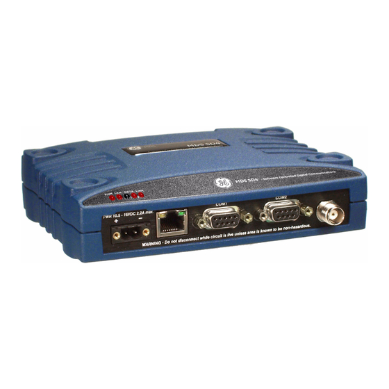
1.0 INTRODUCTION This Reference Manual is one of two books provided for users of the MDS SD Series Transceiver (Figure 1) operating in x710 Mode. It con- tains an overview of common applications, installation planning data, technical specifications, troubleshooting, and a listing of software com- mands. -
Page 12: Electronic Manuals
1.2 Electronic Manuals All SD Series manuals are available in printed or electronic form. Download electronic manuals from our web site at www.gemds.com. The web site also contains links to Application Bulletins and other product information. SD Series Reference Manual (x710 Mode) MDS 05-4670A01, Rev. -
Page 13: Product Description
2.0 PRODUCT DESCRIPTION The SD Transceiver is a software-configurable, industrial radio for use in licensed data acquisition networks. It can be interfaced with a variety of data control equipment including remote terminal units (RTUs), pro- grammable logic controllers (PLCs), flow computers, and similar devices. -
Page 14: Key Product Features
2.2 Key Product Features The transceiver is designed to meet the demanding needs of today’s industrial wireless networks in a compact, rugged package. It offers an array of features in one hardware platform: • Ethernet & serial interfaces—ideal for migration to IP networks •... -
Page 15: Operating Modes And Applicable Manuals
2.4 Operating Modes and Applicable Manuals SD Transceivers can be configured to operate in any one of three modes: • x710 Mode—This mode provides direct, drop-in compatibility with MDS x710 (4710 or 9710) transceivers, and uses the same core command set as these radios. It is ideal for use in systems containing a mix of newer SD radios and legacy MDS x710 units. -
Page 16: Accessories And Spares
2.5 Accessories and Spares Table 1 lists common accessories and spare items for the transceiver. GE MDS also offers an Accessories Selection Guide listing additional items that can be used with the product. Contact your factory represen- tative or visit to obtain a copy of the guide. -
Page 17: Point-To-Point System
lines coming from each remote monitor. In this type of system, there is a modulator/demodulator (modem) at the main computer and at each remote site, usually built into the remote monitor itself. Since the cost of leasing a dedicated-pair phone line is quite high, wireless technology is often used as a cost-effective alternative. -
Page 18: Continuously-Keyed Versus Switched-Carrier Operation
Continuously-Keyed versus Switched-Carrier Operation The keying behavior of the master station can be used to describe the operation of an MAS system. Continuously-Keyed operation means the master station transmitter is always keyed and an RF carrier is always present, even when there is no data to send. -
Page 19: Mounting Options
Figure 6. Typical Remote Station Arrangement 4.2 Mounting Options The transceiver is normally provided with flat mounting brackets attached to the bottom of the radio as shown in Figure 7. An optional 35 mm DIN rail mounting bracket is also available. See “Optional DIN Rail Mounting”... -
Page 20: Optional Din Rail Mounting
NOTE: To prevent moisture from entering the radio, do not mount the case with the cable connectors pointing up. Also, dress all cables to prevent moisture from running along the cables and into the radio. Transceiver dimensions are shown in Figure 8. Figure 8. -
Page 21: Antennas And Feedlines
Antennas of this type are available from several manufacturers, including GE MDS. Contact your factory representative for details. Invisible place holder Figure 10. Typical Yagi Antenna (mounted to mast) Feedlines The selection of an antenna feedline is very important. -
Page 22: Dc Power Connection
Table 3. Signal Loss in Coaxial Cables (at 400 MHz) 10 Feet 50 Feet 100 Feet 200 Feet Cable Type (3.05 Meters) (15.24 Meters) (30.48 Meters) (60.96 Meters) RG-8A/U 0.51 dB 2.53 dB 5.07 dB 10.14 dB 1/2 inch HELIAX 0.12 dB 0.76 dB 1.51 dB... -
Page 23: Grounding Considerations
4.5 Grounding Considerations To minimize the chance of damage to the transceiver and connected equipment, a safety ground (NEC Class 2 compliant) is recommended which bonds the antenna system, transceiver, power supply, and con- nected data equipment to a single-point ground, keeping all ground leads as short as possible. -
Page 24: Com1 In Analog Operation
Invisible place holder > DB-9 MALE DB-9 FEMALE < (RADIO SIDE) (COMPUTER) Figure 13. COM1 Wiring to Computer for Management Table 5. COM1 Pin Descriptions Input/ Number Output Pin Description No function RXD (Received Data)—Supplies received data to the connected device. TXD (Transmitted Data)—Accepts TX data from the connected device. -
Page 25: Com2 (Data) Connections
4.7 COM2 (Data) Connections port (Figure 14) is used to connect the radio to an external COM2 DTE telemetry device supporting the EIA/RS-232 or EIA/RS-485 (bal- anced) format, depending on how the radio is configured. Typically, a straight-through DB-9 cable is used to connect to . - Page 26 Table 7. COM2 Pin Descriptions—RS/EIA-232 Mode Input/ Number Output Pin Description DCD (Data Carrier Detect/Link)—A high (asserted) indicates signal received. RXD (Received Data)—Supplies received data to the connected device. TXD (Transmitted Data)—Accepts TX data from the connected device. Sleep Mode Input—Grounding this pin places the radio in a low power consumption mode.
-
Page 27: Ethernet Interface (Rj-45)
COM2 PORT NOTES: RXD+ / RXB and RXD– / RXA are data sent to the radio to be transmitted • • RXD+ / RXB is positive with respect to RXD– / RXA when the line input is a “0” • TXD+ / TXB and TXD– / TXA are data received by the radio and transmitted •... -
Page 28: Step-By-Step Installation
5.0 STEP-BY-STEP INSTALLATION In most cases, the steps given here are sufficient to install the trans- ceiver. Refer to “INSTALLATION PLANNING” on Page 8 for addi- tional details. 1. Mount the transceiver. Attach the mounting brackets to the bottom of the transceiver case (if not already attached), using the four 6-32 x 1/4 inch (6 mm) screws supplied. -
Page 29: Initial Startup & Checkout
5.1 Initial Startup & Checkout In-service operation of the transceiver is completely automatic. Once the unit has been properly installed and configured, operator actions are limited to observing the front panel LED indicators for proper operation. If all parameters are correctly set, operation of the radio can be started by following these steps: 1. -
Page 30: Serial Vs. Telnet Access, And The Device Manager
Serial vs. Telnet Access, and the Device Manager There are three methods available to communicate with the transceiver for configuration and management purposes: Serial ( DB9 con- COM1 nector), Telnet ( RJ-45 connector), and the web-based ETHERNET Device Manager. Both serial and telnet present identical screens, but the method of access is different for each. -
Page 31: Transceiver Management
3. Press the several times at half-second intervals to ENTER choose and select the correct baud rate. This will result in > prompt. Invisible place holder Transceiver PC Running Terminal Session DB-9M to COM1 Port Figure 17. PC Connection to Transceiver NOTE: TX and RX frequencies might not be set when the radio is shipped from the factory, depending on ordering options. - Page 32 Table 11. Command Summary (Continued) Command name Function ASENSE [HI, LO] Details Set/display the state of the alarm output signal to Page 25 ACTIVE HI or ACTIVE LO. AUDIO [ON, OFF] Details Set/display the receive audio monitor mode for Page 26 modems.
- Page 33 Table 11. Command Summary (Continued) Command name Function INIT [P-20] Details Page 30 Configure radio for service within a P-20 Protected Network Chassis. IPCONFIG Details Page 31 Ethernet interface configuration. KEY Details Page 31 Key the radio (transmitter ON). This is generally a radio test command.
-
Page 34: Detailed Command Descriptions
Table 11. Command Summary (Continued) Command name Function RXTOL [NORMAL or Set/display the custom receive tolerance to CUSTOM] Details Page accommodate issues experienced with some x790 masters. RXTOT [NONE, 1-1440] Set/display the value of the receive time-out timer. Details Page 36 SAVECONFIG Details Saves a user configuration. -
Page 35: Alarm
Authorization Key The transceiver’s feature set may be expanded (if all features are not currently enabled) by entering a new authorization key, which can be purchased from GE MDS. Contact the factory to obtain a new Authori- zation Key. ALARM command displays a summary of the radio’s current oper-... -
Page 36: Audio [On, Off]
AUDIO [ON, OFF] Used to set or display Audio Monitor/Orderwire functionality (on or Audio Monitor/ Orderwire Status off). If is selected, the radio’s transmit functionality will AUDIO ON switch to analog whenever PTT is asserted. BAUD [xxxxx abc] This command sets (or displays) the communication attributes for the Data Interface Port Baud Rate port (COM2). -
Page 37: Ckey [On-Off]
If data buffering is , the radio operates in seamless mode. Data bytes are sent over the air as quickly as possible, but the receiver buffers (stores) the data until enough bytes have arrived to cover worst-case gaps in transmission. This mode of operation is required for protocols such as MODBUS™... -
Page 38: Datakey [On, Off]
DATAKEY [ON, OFF] command enables or disables the ability of the radio to key Key on Data Activity DATAKEY the transmitter as data is received at the connector. DATA INTERFACE Asserting RTS keys the radio regardless of this command setting. is set to , the radio will key when a full data-character is DATAKEY... -
Page 39: Dtype [Node/Root]
NOTE: The radio is configured by default to be in DLINK mode. The port automatically determines the connected baud rate COM1 (within the range of 1200–115200 bps). Enter a series of Return Key presses about a half second apart until the prompt >... -
Page 40: Init
INIT command is used to re-initialize the radio’s operating parame- Initialize EEPROM INIT Defaults ters to the factory defaults. This can be helpful when trying to resolve configuration problems that might have resulted from the entry of one or more improper command settings. If you are unsure of which com- mand setting caused the problem, this command allows you to get back to a known working state. -
Page 41: Ipconfig
IPCONFIG Ethernet interface configuration. This command is used to display or Ethernet Configuration change the configuration of the Ethernet interface. The command can be used in several ways: • alone displays all current network settings. IPCONFIG • is used to switch between DHCP and IPCONFIG DHCP [ON/OFF] static addressing. - Page 42 Table 12. Modem Selection vs. Speed, Bandwidth & Sensitivity Over-the-air B/W (kHz) Approximate Modem Type Speed (bps) Selection Sensitivity Modem 4800F 4800 6.25 -108 dBm 9600 12.5 -106 dBm Modem 9600B 4800 12.5 -110 dBm Modem 4800B 1200 12.5 -110 dBm Modem BELL Modem V23 1200...
-
Page 43: Owm [Xxx
When the transceiver is used to replace an existing MDS x710 radio, it is important to verify that the modem selection is compatible with the unit replaced. Table 13 lists SD modem type selections and the compat- ible x710 models they can be used with. Table 13. -
Page 44: Port [Rs232, Rs485]
PORT [RS232, RS485] Set or show data port interface settings. COM2 Settings COM2 PTT [0–255] Push-to-Talk Delay This command sets or shows the key-up delay in milliseconds. This timer specifies how long to wait after the radio receives a key signal, before actually keying the radio. -
Page 45: Rtskey [On, Off]
NOTE: The RSSI samples the incoming signal for one to two seconds before providing an average reading to the connected PC. RTSKEY [ON, OFF] Used to set/display how the radio responds to RTS keying. The default RTS Keying Behavior setting is causes the radio to respond to RTS by RTSKEY OFF RTSKEY ON... -
Page 46: Rxtol [Normal Or Custom]
RXTOL [NORMAL or CUSTOM] RX Tolerance command allows custom configuration of the receive toler- RXTOL ance, to improve performance with legacy radios (x790, x310, and so on). RXTOT [NONE, 1-1440] command selects or shows the receive time-out timer value Loss of RX Data RXTOT Alarm Time in minutes. -
Page 47: Spectrum [Xxx.xx]
The SNR is an indication of the received signal quality. A value of 10 dB represents a very poor signal. A value of 24 dB represents a very good signal. When the SNR command is used, it causes the port to enter an DIAG. -
Page 48: Stat
STAT This command shows the current alarm status of the transceiver. Alarm Status If no alarms exist, the message appears. NO ALARMS PRESENT If an alarm does exist, a two-digit code (00–31) is displayed and the alarm is identified as “Major” or “Minor.” A brief description of the alarm code is also given. -
Page 49: Tot [1-255, On, Off]
TOT [1-255, ON, OFF] This command sets or shows the transmitter Time-out Timer value TX Timeout-Timer (1–255 seconds), as well as the timer status ( ). If the timer is on, and the radio remains keyed for a longer duration than the value, the transmitter is automatically unkeyed. -
Page 50: Troubleshooting
7.0 TROUBLESHOOTING Successful troubleshooting of the radio system is not difficult, but it requires a logical approach. It is best to begin troubleshooting at the master station, as the rest of the system depends on the master for polling commands. If the master station has problems, the operation of the entire network might be compromised. -
Page 51: Major Alarms Vs. Minor Alarms
The codes shown are a subset of a larger pool of codes used for various GE MDS products. For this reason, the table does not show a sequential listing of all code numbers. Only the codes applicable to this product are shown, and this list is subject to change with product revi- sion. - Page 52 Table 14. Event Codes (Continued) Event Event Code Class Description Minor A socket operation failed. Minor AP not available. Status Forced restart of Ethernet interface. Status Reprogramming in progress. Inform Firmware update successful. Inform Reprogramming aborted. Inform Remote rebooted. SD Series Reference Manual (x710 Mode) MDS 05-4670A01, Rev.
-
Page 53: Technical Reference
50.0 kHz NOTE: This information subject to change depending on specific modem configuration. For emission designator information, consult the FCC web site for latest “GE MDS” grants: http://transition.fcc.gov/oet/ea/fccid/. Emission designators are subject to change pending new FCC additions and approvals. - Page 54 Duty Cycle: Variable up to 100%, dependent on application. Continuous key operation not recommended. Output Impedance: 50 Ω Product FCC ID IC ID E5MDS-SD1 101D-SD1 E5MDS-SD2 101D-SD2 E5MDS-SD2-1 E5MDS-SD4 101D-SD4 E5MDS-SD4-1 101D-SD4-1 E5MDS-SD9 101D-SD9 E5MDS-SD9-1 DATA CHARACTERISTICS Signaling Types: RS-232/485; DB-9 Female connector Ethernet 10/100 Mbps;...
-
Page 55: Performing Network-Wide Remote Diagnostics
8.2 Performing Network-Wide Remote Diagnostics Diagnostics data from a remote radio can be obtained by connecting a laptop or personal computer running compatible NMS software, such as Element Manager or InSite,to any radio in the network. Figure 19 shows a sample arrangement for performing network-wide remote diagnostics. Invisible place holder DTYPE NODE... -
Page 56: User-Programmable I/O Functions - Pending
1. Program one radio in the network as the root radio by entering the command at the radio. DTYPE ROOT 2. At the root radio, use the commands DLINK ON DLINK [baud rate] to configure the diagnostic link protocol on the Management Port. 3. -
Page 57: Physical Interface
In analog-only mode, carrier detect is based on squelch status. Mixed analog/digital operation is useful for orderwire application, or for analog systems that need to make use of GE MDS Network-Wide Diag- nostics. Operation is enabled by selecting a digital modem type (for example, ) and selecting . -
Page 58: Upgrading The Radio's Firmware
SQUELCH AUTO 8.5 Upgrading the Radio’s Firmware From time to time, GE MDS releases new firmware for its radio prod- ucts to take advantage of engineering improvements or to add opera- tional features. New firmware can be installed into existing radios in the field, bringing them up to date with the firmware shipped with new units. -
Page 59: Web Method
Three methods can be used to load new firmware into the radio: Web reprogramming, TFTP, and Serial Transfer. Firmware reprogram- ming is best handled using the web-based Device Manager. Instructions for these methods of transfer are given below, beginning with Web pro- gramming. -
Page 60: Tftp Method
(a Windows-based TFTP .mpk server can be downloaded from the GE MDS Web site at: www.gemds.com/Resources/TechnicalSupport 3. The IP address of the PC running the TFTP server. If you do not know your computer’s IP address, use the... - Page 61 LED on the radio’s port lights and stays lit. This verifies that the network is functioning. 2. Launch the TFTP server on the PC. If using the GE MDS TFTP Server, click the tab (A in Figure 22 below) and modify the...
-
Page 62: Serial Transfer Method
4. Use the command to configure the IP host and file to program. tftp For example: >tftp host 10.4.147.63 >tftp file SDx-3_0_0 5. Enter to begin reprogramming. The file is loaded into the tftp get radio’s inactive image. A series of progress messages display every few seconds indicating the reprogramming status, followed by when the process is finished. - Page 63 Invisible place holder Transceiver PC Running Terminal Session DB-9M to COM1 Port Figure 23. PC Connection to Transceiver (Serial) Follow the steps below for serial transfer upgrade. NOTE: Serial reprogramming takes several minutes at 115200 bps baud rate (the recommended speed), but reprogramming is possible at lower baud rates.
-
Page 64: Error Messages During File Transfers
NOTE: If a firmware installation fails, the radio is left with the original active image intact, and the inactive image will be unusable. Reprogramming should be attempted again. Error Messages During File Transfers It is possible to encounter errors during a file transfer. In most cases errors can be quickly corrected by referring to Table 16. -
Page 65: Dbm-Watts-Volts Conversion Chart
8.6 dBm-Watts-Volts Conversion Chart Table 17 is provided as a convenience for determining the equivalent wattage or voltage of an RF power expressed in dBm. Table 17. dBm-Watts-Volts Conversion—for 50 Ohm Systems dBm V dBm V dBm mV 100.0 200W .225 1.0mW 0.80... -
Page 66: Glossary Of Terms
9.0 GLOSSARY OF TERMS If you are new to digital radio systems, some of the terms used in this guide may be unfamiliar. The following glossary explains many of these terms and will prove helpful in understanding the operation of the trans- ceiver. - Page 67 Multiple Address System—See MAS. Network-Wide Diagnostics—An advanced method of controlling and interrogating GE MDS radios in a radio network. Non-intrusive diagnostics—See Passive messaging. MDS 05-4670A01, Rev. E SD Series Reference Manual (x710 Mode)
- Page 68 Passive messaging—This is a mode of diagnostic gathering that does not interrupt SCADA system polling communications. Diagnostic data is collected non-intrusively over a period of time; polling messages are carried with SCADA system data (contrast with active messaging). Payload data—This is the application’s user communication data which is sent over the radio network.
- Page 69 NOTES MDS 05-4670A01, Rev. E SD Series Reference Manual (x710 Mode)
- Page 70 SD Series Reference Manual (x710 Mode) MDS 05-4670A01, Rev. E...
- Page 71 RXTOT (set/display receive time-out timer value) 36, 39 SCD (set/display soft-carrier dekey delay) 36 Active messaging (defined) 56 SER (display radio serial number 36 Alarms SHOW (display DC voltage, data port, RF power) 36 alarm code definitions 41 SNR (display signal-to-noise ratio) 36 major vs.
- Page 72 DTE (Data Terminal Equipment), defined 57 LEDs DTYPE command 29 PWR 19 use of 46 status indicators, illustrated 19 DUMP command 29 Loss. See Signal Enable/disable MAS (Multiple Address System) 6 continuous keying (CKEY command) 27 defined 57 internal RTU (RTU command) 35 illustration 7 network-wide diagnostics (DLINK command) 28 Master Station...
- Page 73 mounting the transceiver 9 diagnostics interface 44 network-wide diagnostics 44, 46 environment 44 operation 21 power 44 troubleshooting 40–41 receiver 44 Product receiver system 43 description 3, 4 transmitter 43 display model number code (MODEL command) 31 transmitter system 43 display radio serial number (SER command) 36 SREV command 37 model number codes 6...
- Page 74 MDS 05-4670A01, Rev. E SD Series Reference Manual (x710 Mode)
- Page 75 IN CASE OF DIFFICULTY... GE MDS products are designed for long life and trouble-free operation. However, this equipment, as with all electronic equipment, may have an occasional component failure. The following information will assist you in the event that servicing becomes necessary.
- Page 76 GE MDS, LLC 175 Science Parkway Rochester, NY 14620 Telephone: +1 585 242-9600 FAX: +1 585 242-9620 www.gemds.com...