GE MDS SD Series Technical Manual
Secure, long range ip/ethernet & serial
Hide thumbs
Also See for MDS SD Series:
- Reference manual (148 pages) ,
- Technical manual (116 pages) ,
- Quick start manual (4 pages)
Table of Contents
Advertisement
Quick Links
Advertisement
Table of Contents

Related Manuals for GE MDS SD Series


Summary of Contents for GE MDS SD Series
- Page 1 MDS SD Series Secure, Long Range IP/Ethernet & Serial Covering ES/SS Units with Firmware Version 5.x Applies to all models EXCEPT those operated in x710 Mode. For x710 mode operation, refer to Publication 05-4670A01. MDS 05-4846A01, Rev. H November 2013...
- Page 2 Quick-Start instructions for this product are contained in publication 05-4847A01. All GE MDS manuals and updates are available online at www.gemds.com.
-
Page 3: Table Of Contents
TABLE OF CONTENTS 1.0 INTRODUCTION ........................1 1.1 Conventions Used in This Manual ....................1 1.2 New Features in this Release ....................... 2 2.0 PRODUCT DESCRIPTION....................3 2.1 Front Panel Connectors and Indicators ..................3 2.2 Key Product Features ........................4 Media Access Control (MAC)...................... - Page 4 4.7 Serial Data Interfaces ........................24 COM1 (Serial) Connection......................24 COM2 (Data) Connections......................25 5.0 STEP-BY-STEP INSTALLATION ..................28 5.1 Initial Configuration ........................29 Web-Based Management ......................29 Web Browser Connection ......................30 Alternative Management Methods ....................32 5.2 Initial Startup & Checkout ......................33 Ethernet Connector LEDs ......................
- Page 5 9.0 GLOSSARY OF TERMS & ABBREVIATIONS ..............104 Copyright and Trademark This manual and all software described herein is protected by Copyright: 2013 GE MDS, LLC. All rights reserved. GE MDS, LLC reserves its right to correct any errors and omissions in this publi- ® cation. Modbus is a registered trademark of Schneider Electric Corporation.
- Page 6 If you have additional ques- tions or need an exact specification for a product, please contact GE MDS using the information at the back of this guide. In addition, manual updates can be found on our web site at www.gemds.com...
- Page 7 These systems will reuse or recycle most of the materials found in this equipment in a sound way. Please contact GE MDS or your supplier for more information on the proper dis- posal of this equipment.
- Page 8 BSD License Information The SD Series products contain source code originally released as part of “WPA Supplicant” which is copyrighted as indicated below and is redistributed under the terms of the BSD license: WPA Supplicant Copyright (c) 2003-2010, Jouni Malinen <j@w1.fi> and contributors All Rights Reserved.
-
Page 9: Introduction
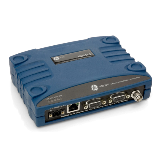
1.0 INTRODUCTION This manual is one of two publications for users of the MDS SD Series Transceiver shown in Figure 1. It contains an overview of common applications, installation planning data, specifications, troubleshooting, and instructions for using the web-based Device Manager. This manual is intended for technical personnel who perform network design, config- uration, and troubleshooting of the equipment. -
Page 10: New Features In This Release
Authorization Some features of the radio are dependent on purchased options and Features applicable regulatory constraints. A “key” icon is shown near the heading of any such features. In some cases a feature upgrade may be available. Contact your sales representative for additional information. 1.2 New Features in this Release The SD transceiver has been updated to include the following function- ality in the latest release of the product:... -
Page 11: Product Description
2.0 PRODUCT DESCRIPTION The transceiver is a software-configurable, industrial radio for use in licensed data acquisition networks. It may be interfaced with a variety of data control equipment including remote terminal units (RTUs), pro- grammable logic controllers (PLCs), flow computers, and similar devices. -
Page 12: Key Product Features
2.2 Key Product Features The transceiver is designed to meet the demanding needs of today’s wireless networks in a compact, and rugged package. It offers an array of features in a single hardware platform: • Software-configurable via a built-in Device Manager—no man- ual controls or adjustments. -
Page 13: Vlan Capability
and other units are designated as Remotes. The AP serves as the con- troller of the RF network. Remotes request permission from the AP to use the RF channel before sending payload data, thus avoiding collisions of data, and creating a highly reliable wireless network. The MAC is responsible for allocating which unit gets access to the broadcast medium (the RF channel), when, and for how long. -
Page 14: Peer-To-Peer Capability
Peer-to-Peer Capability Peer to Peer capability is available in Packet w/MAC mode only. It allows Remote radios in the same radio network to pass data directly between each other. When the Peer-to-Peer functionality is enabled on the Remote, both the Remote and the AP will be able to pass data in the system. - Page 15 Standard Modes • Packet Mode—Payload data from the radio’s serial and Ethernet (Modes covered by ports is assembled into packets and transmitted over the air. this manual) Packet mode supports Ethernet Bridging, AES 128-bit encryp- tion, and Virtual Radio Channels (VRC). This mode requires an all-SD radio network.
-
Page 16: Accessories And Spares
2.5 Accessories and Spares Table 1 lists common accessories and spare items for the transceiver. GE MDS also offers an Accessories Selection Guide listing additional items that may be used with the product. Visit or contact www.gemds.com your factory representative to obtain a copy of the guide. -
Page 17: Dual Protected Configurations
Invisible place holder Figure 4. Protected Network Station With two transceivers and two power supplies installed, the unit con- tinues to communicate even if a failure occurs in one of the transceivers, or its associated power supply. This capability is important in critical applications where uninterrupted service is required. - Page 18 SDxDP The SDxDP is a protected, full duplex Master or Repeater site configu- Configuration ration. This consists of two SDxP chassis described earlier, with appro- priate interconnect cabling between the units. The radios in one SDxP are configured with the transmit frequency and the radios in the other are configured with the receive frequency.
-
Page 19: Typical Applications
A number of variations are possible; If you have unique requirements not found here, it is recommended that you consult a support specialist at GE MDS. Contact information is provided at the back of this manual. 3.1 Operating Parameters The transceiver can operate in both poll-response and “push”... -
Page 20: Example Systems
3.2 Example Systems The following sections describe common system arrangements for the transceiver. Other variations are possible, and if you have questions about a specific application not covered here, you may contact your fac- tory representative using the information at the back of this guide. For typical radio settings in these systems, refer to Table 2 on Page 11. -
Page 21: Ip Payload/Ethernet Polling And Terminal Server Operation
Invisible place holder Figure 6. Typical Point-to-Point Link IP Payload/Ethernet Polling and Terminal Server Operation Modern data/control networks often employ IP/Ethernet connectivity throughout the system. The transceiver is well suited to provide connec- tivity between such sites using its RJ-45 modular connector on the front panel and enabling Ethernet Bridging capabilities. -
Page 22: Port Sharing With Multiple Hosts
The type of network shown in Figure 7 can also be used for general Ethernet bridging as supported by the over-the-air bandwidth of the system. Bridge filters in the radio may be set to reduce Ethernet traffic over the RF channel, and improve performance. Port Sharing with Multiple Hosts The transceiver allows for several external data networks to use the same RF network without confusing the data streams. -
Page 23: Push Communication (Report-By Exception)
Device Settings Screen Radio Mode: Packet w/MAC MASTER RADIO To Ethernet Port HOST COMPUTER (Host B) HOST COMPUTER (Host A) Ethernet Serial HOST C To COM2 Serial Port REMOTE RADIO REMOTE RADIO (One of several possible sites) (One of several possible sites) Ethernet Co-located RTUs Responding to... -
Page 24: Ip Polling Of Two Serial Ports On One Remote
In this example, the Host Computer is connected directly to the radio’s Ethernet port and the RTUs at the Remote sites are connected to the transceiver via the radio’s serial data ports. The IP Payload fea- COM2 ture, used at the Master, efficiently passes TCP/UDP payload over the air, and eliminates the need for an external terminal server. - Page 25 Packet w/MAC is the recommended method of operation when both serial ports are used to pass payload data if there are two hosts (e.g., Port Sharing with multiple host case). If there is a single host polling all units, packet or transparent mode is the preferred option even if there are two RTUs connected to a Remote radio.
-
Page 26: Installation Planning
4.0 INSTALLATION PLANNING This section covers pre-installation factors that should be considered when installing the transceiver in the field. Careful planning will help achieve optimal performance from the transceiver. After reviewing this section, refer to the step-by-step installation procedures beginning on Page 28. Figure 11 shows a typical station arrangement. -
Page 27: Chassis Dimensions
4.1 Chassis Dimensions Figure 12 shows the external chassis dimensions of the SD Transceiver. Invisible place holder Figure 12. Transceiver Dimensions 4.2 Mounting Bracket Options The transceiver is normally provided with flat mounting brackets attached to the bottom of the radio as shown in Figure 13. An optional 35 mm DIN rail mounting bracket is also available, and is described below. -
Page 28: Optional Din Rail Mounting
A directional Yagi (Figure 15) or corner reflector antenna is generally used at remote sites to minimize interference to and from other users. Antennas of this type are available from several manufacturers, including GE MDS. Contact your factory representative for details. SD Series Technical Manual MDS 05-4846A01, Rev. H... -
Page 29: Feedlines
Invisible place holder Figure 15. Typical Yagi Antenna (mounted to mast) Feedlines The selection of an antenna feedline is very important. Poor quality cable should be avoided as it will result in power losses that may reduce the range and reliability of the radio system. The tables which follow show the approximate losses that will occur when using various lengths and types of coaxial cable in the 200, 400 and 900 MHz bands, respectively. -
Page 30: Dc Power Connection
Table 5. Signal Loss in Coaxial Cables (at 900 MHz) 10 Feet 50 Feet 100 Feet 200 Feet Cable Type (3 Meters) (15 Meters) (30.5 Meters) (61 Meters) RG-8A/U 0.85 dB 4.27 dB 8.54 dB 17.08 dB 1/2 inch HELIAX 0.23 dB 1.15 dB 2.29 dB... -
Page 31: Ethernet Data Interface (Rj-45)
Normally, the transceiver is adequately grounded if the supplied flat mounting brackets are used to mount the radio to a well-grounded metal surface. If the transceiver is not mounted to a grounded surface, it is rec- ommended that a safety ground wire be attached to one of the mounting brackets or a screw on the transceiver’s case. -
Page 32: Serial Data Interfaces
NOTE: Not all PCs have a serial port. If one is not available, a USB-to-Serial adapter and appropriate driver software may be used to provide serial connectivity. These adapters are avail- able from several manufacturers, including GE MDS. COM1 (Serial) Connection The default factory settings for the radio’s... -
Page 33: Com2 (Data) Connections
Figure 19. COM1 Wiring for PC Management Table 7. COM1 Pin Descriptions Radio Number Input/ Pin Description Output No function RXD (Received Data)—Supplies received data to the connected device. TXD (Transmitted Data)—Accepts TX data from the connected device. No function Ground—Connects to ground (negative supply potential) on chassis. - Page 34 Table 8. COM2 Pin Descriptions—Radio in RS-232 Mode Radio Number Input/ Pin Description Output DCD (Data Carrier Detect/Link)—A high indicates signal received. RXD (Received Data)—Supplies received data to the connected device. TXD (Transmitted Data)—Accepts TX data from the connected device. Sleep Mode Input—Grounding this pin places the radio in a low power consumption mode.
- Page 35 COM2 PORT NOTES: RXD+ / RXB and RXD– / RXA are data sent to the radio to be transmitted • • RXD+ / RXB is positive with respect to RXD– / RXA when the line input is a “0” • TXD+ / TXB and TXD– / TXA are data received by the radio and transmitted •...
-
Page 36: Step-By-Step Installation
5.0 STEP-BY-STEP INSTALLATION In most cases, the steps given here are sufficient to install the trans- ceiver. Refer to “INSTALLATION PLANNING” on Page 18 for addi- tional details, as required. 1. Mount the transceiver. Attach the mounting brackets to the bottom of the transceiver case (if not already installed), using the three 6-32 x 1/4 inch (6 mm) screws supplied. -
Page 37: Initial Configuration
The unit is designed for use with negative-ground systems only. The CAUTION power supply should be equipped with overload protection (NEC POSSIBLE Class 2 rating), to protect against a short circuit between its output EQUIPMENT terminals and the radio’s power connector. DAMAGE 5. -
Page 38: Web Browser Connection
Web Browser Connection This section describes connection and use of the radio’s built-in Device Requirements Manager. To connect to the radio and manage it via the Device Man- ager, you will need the following: • A PC with a web browser program installed. •... - Page 39 Invisible place holder Figure 23. Login Screen 4. The Basic Setup Wizard (Figure 24) begins automatically upon con- Using the Basic Setup Wizard nection to a new factory shipped radio. It may also be started manu- ally by selecting , and then clicking .
-
Page 40: Alternative Management Methods
The following methods are for use where web-based management is not available: • Serial—( DB9 connector). This is the “console terminal” COM1 method of control commonly used on earlier GE MDS radios. • Telnet—( RJ-45 connector). Telnet offers essentially ETHERNET the same capabilities as Serial control, but may be performed either through a local connection, or over a network. -
Page 41: Initial Startup & Checkout
5.2 Initial Startup & Checkout In-service operation of the transceiver is completely automatic. Once the unit has been properly installed and configured as described above, operator actions are limited to observing the front panel LED indicators for proper operation. If all parameters are correctly set, operation of the radio can be started by following these steps: 1. -
Page 42: Optimizing The Radio Network
5.3 Optimizing the Radio Network With basic configuration complete, there are several additional settings that can be made to optimize the radio system. The settings below should be reviewed and changed as necessary to suit your particular application. Modem Type Setting All radios in the network must be set to the same modem type and speed. -
Page 43: Ethernet Settings
Ethernet Settings The local Ethernet connection must be configured to conform to the needs of the local Ethernet network. The Configuration>>Communication screen is used to set/view these settings. Here Ports>>IP/IP2 Configuration are some general points that apply to Ethernet settings: •... -
Page 44: Using The Device Manager
6.0 USING THE DEVICE MANAGER The radio contains a built-in management system known as a Device Manager. This web-based tool is accessed with a PC connected to the radio’s Ethernet port as shown in Figure 25. It offers an intuitive method for managing your radio and performing common maintenance tasks. -
Page 45: Overview Screen
Invisible place holder Figure 26. Overview Summary Screen Overview Screen screen (Figure 26) provides a read-only view of all key set- Overview tings and operating conditions for the radio. The Health & Maintenance Sum- , in particular, can help you quickly spot changes in operating mary conditions. -
Page 46: Management Tasks
6.2 Management Tasks Table 11 shows a listing of commonly-needed tasks and the appropriate sections of the Device Manager to refer to. The table can be used as a quick reference before consulting the more detailed screen information which follows in this section. Table 11. - Page 47 Table 11. Device Manager Quick Reference (Continued) Task If you wish to... Refer to this Screen/Section Category Set RF Output Power, Modem Type, RX/TX Configuration>>Radio, Frequency Basic Settings, Page 43 View/Set Soft-Carrier Dekey status, RX/TX Configuration>> Time-Out options Radio>> Advanced Settings, Page 53 View/Set Data-Key and RTS-Key settings Configuration>>...
- Page 48 Table 11. Device Manager Quick Reference (Continued) Task If you wish to... Refer to this Screen/Section Category View Serial No., Model 1 (software), Model 2 Overview>> (hardware) version, Firmware Version, Build SD Summary, Page 37 Date Set Owner Name/Message, enable/disable Configuration>>...
- Page 49 Table 11. Device Manager Quick Reference (Continued) Task If you wish to... Refer to this Screen/Section Category Configure COM1 settings (Startup mode, Data Configuration>> Baud Rate, Data format, Virtual Radio Communication Ports>> Channels–VRCs) COM1 Port Settings, Page 67 Configure COM2 settings (Mode, Baud Rate, Configuration>>...
- Page 50 Table 11. Device Manager Quick Reference (Continued) Task If you wish to... Refer to this Screen/Section Category View logged Events Maintenance & Status>> Event Log, Page 73 Set alarm signal output (active high/low) Maintenance & Status>> Alarm Summary>> Alarm Signal Configuration, Page 74 Conduct an Alarm Test Maintenance &...
-
Page 51: Configuration Screens
6.3 Configuration Screens screen (Figure 27) contains a number of key settings for Configuration the radio, including RF parameters, modem selection, packet settings, MAC parameters, and several advanced settings. Individual screens may be selected beneath on the left side of the screen. Configuration Figure 27. - Page 52 any of the selections shown in Table 12. The table also lists modem sensitivity ratings for the various modems. Note that some modem choices are limited based on the model purchased. Table 12. Modem Selection vs. Speed, Bandwidth & Sensitivity Over-the-air B/W (kHz) Approximate...
- Page 53 • Provides the possibility for Frequency Re-use. SysID System ID— offers nine unique choices including the default value of NONE The setting is required for mixed networks comprised of NONE MDS legacy and SDx products. SDx-only networks can utilize the Frequency Re-use feature by setting the System ID to a com- mon value [ ] for all radios in a specific network.
- Page 54 Invisible place holder Figure 29. System ID Example—Invalid Arrangement (Will not operate properly with SD Transceivers) Device Settings • —An owner name and message may be Owner Name/Owner Message entered for the radio for informational purposes. These are “free-form” fields which do not affect the operation of the radio in any way.
- Page 55 port is what actually puts the radio to sleep. This signal COM2 must be supplied by the equipment connected to the radio (i.e., RTU, PLC, etc.). Sleep mode is not intended for use on Master radios. • —The behavior of the radio’s LEDs COM/DATA COM LED Mode...
- Page 56 Packet Settings • —Timing setting used to delimit a COM1/COM2 Port Inter-Packet Gap packet on the serial interface for radios operating in Packet Mode. Too short of a time can cause serial streams to be combined into one large packet instead of two smaller ones. Too long of a time can effectively slow down the communications channel.
-
Page 57: Store And Forward Operation
screen (see “Diagnostic Settings” on Diagnostic Settings Page 52). A Store and Forward device is a radio designated to retransmit data to/from an outlying Remote (see SAF Network, below). • —(AP Only) Selects whether or not a Store and For- SAF Network ward radio is present in the network ( ), or not (... - Page 58 Invisible place holder Figure 30. Store and Forward System Example Store and Forward is available in Packet w/MAC mode and supports all MAC features including collision avoidance, retries, and acknowledge- ments. Furthermore, all major radio features are supported in SAF net- works such as diagnostics, over the air programming, bridging, VRCs, etc.
- Page 59 Traffic Routing: Typically, network radios are immobile, but fading may cause paths to come and go. Because of this, the Master/AP device implements routing to each Remote device. This ensures that only SAF traffic passes through SAF Remotes. Direct traffic is terminated at the local coverage area, keeping efficiency high.
- Page 60 Diagnostic Settings • —This parameter identifies the radio in the wireless network Unit # with a specific ID during diagnostic sessions. This value is defaulted to the last 4-digits of the unit’s Serial Number. Should a network require a Unit # change, the value must be greater than 10000 in decimal (2710 in hexadecimal).
- Page 61 Advanced Settings • —Specifies how long (in ms) to wait after the Soft-Carrier Dekey (ms) removal of the keying signal before actually dropping the trans- mitter’s carrier. The default setting is , but it may be set to any value up to ms.
- Page 62 • —Allows programming a brief time delay Push-To-Talk Delay (ms) after a keying event, which must expire before the radio is allowed to transmit. The allowable range is 0 to 255 ms, with the default being 0. • —Allows programming a brief time delay Clear-To-Send Delay (ms) between when an RTS (ready-to-send) signal is received and when the CTS (clear-to-send) signal is returned.
-
Page 63: Features
Features Bridge Configuration • —Used to enable or disable Ethernet Bridging on the Bridge Mode radio. Default setting is • —Sets the type of bridge filter to be used. Basic Bridge Filter Sel Available selections are: Broadcast/Unicast (All), Unicast and ARP, Unicast Only •... - Page 64 When the Wireless or Ethernet port (AP or Remote) is configured as an Access Port, the radio tags incoming traffic with a VLAN ID, and strips the tag before sending out traffic. This traffic is known as the Data VLAN. Additionally, a second VLAN is assigned for other traffic that is terminated at the radio, such as Web, Telnet, DLINK over TCP, TFTP reprogramming, etc.
- Page 65 Listen Before The transceiver provides a legacy collision avoidance scheme called Transmit (LBT) Listen Before Transmit (LBT). It employs P-Persistent CSMA protocol, Settings which senses channel usage and inhibits transmission if the channel is currently in use. CSMA is an abbreviation for Carrier Sense Multiple Access.
- Page 66 NOTE: The lower the value of the Maximum Wait Time, the higher the chances of collisions occurring over-the-air. Conversely, the higher the value of the Maximum Wait Time, the higher the transmission latency. • —Provides a setting for the maximum wait time (in Timeout (ms) milliseconds) for the channel to become free.
- Page 67 IP Payload is intended to be used in a poll-response system. An Ethernet device at the Master radio sends UDP/TCP poll messages to the Master’s Ethernet port which is configured to listen for data. The poll is sent OTA and a RTU/PLC attached to one of the Remote radios (via serial or Ethernet) responds.
-
Page 68: Understanding The Use Of Virtual Radio Channels (Vrcs)
• —Specifies the IP address associated with the Destination IP Address device connected through the RJ-45 modular connector on the radio’s front panel (typically a PC). Any valid IP address may be entered. • —Used to specify a port number for the RJ-45 Destination IP Port modular connector on the connected device (typically a PC). - Page 69 Any combination of the three VRC numbers may be entered in the selec- tion fields. Figure 31 illustrates the relationship between the VRC set- tings and the routing of data between units. Invisible place holder RADIO 1 IP Payload 1 Data (Talk on VRC-1) Serial COM2 Data (Talk on VRC-2)
- Page 70 NOTE: Available selections vary depending on the mode selected. • —Enables or disables the Terminal Server feature. Status • —Sets the operating mode for the IP port. It may be set to Mode , or UDP Socket TCP Client Socket TCP Server Socket TCP Server/Client to match the service in which it will operate.
-
Page 71: Using The Terminal Server-Typical Example
Using the Terminal Server—Typical Example The following describes a Terminal Server implementation in a radio network. Figure 32 below is referenced in this discussion. Figure 32. Terminal Server Example IP/Radio Network Setup and Configuration The following conditions are assumed for this example: •... - Page 72 2. Navigate to the of Remote 1 and Remote 2 and COM2 Port Settings configure them as listed below (note that VRCs are not used): Mode: RS232 Baud Rate: 115200 bps Format: 8 char bits, no parity, 1 stop bit Buffer: Data Handling ON Device: DCE Talk on: VRC-1...
- Page 73 Invisible place holder Figure 35. Remote 2 Terminal Server Connection On PC3, open a HyperTerminal session and connect to Remote 2’s COM2 port as shown in Figure 36. Figure 36. Remote 2 COM2 Port Connection Type “hello” in the Remote 1 Terminal Server window. Note delivery of the message only to the Remote 1 COM2 Port window (see Figure 37).
- Page 74 Type “how are you” in the Remote 2 terminal server window (see Figure 38). Note delivery of the message only to the Remote 2 COM2 Port window. Type “good” in the Remote 2 COM2 Port window. Note delivery of message only to Remote 2 terminal server window. Figure 38.
-
Page 75: Communications Ports
Peer-to-Peer (Peer2Peer) • — Determines if the AP will allow Rebroadcast Allowed (AP only) enabled Peers to communicate through the AP to other enabled Peers (serial data only). • —Determines if the AP will allow Ethernet Rebcast Allowed (AP only) enabled Peers to communicate through the AP to other enabled Peers (Ethernet data only). - Page 76 • —The default data format for the transceiver is 8 char- Data Format acter bits, no parity, and 1 stop bit (8N1). A number of settings are possible as listed below: 8 character bits, no parity, 1 stop bit (Default) 8 character bits, no parity, 2 stop bits 8 character bits, odd parity, 1 stop bit 8 character bits, odd parity, 2 stop bits...
- Page 77 • —The transceiver’s buffer provides a way of handling data Buffer “over-runs,” where more data is passing through the port COM2 than can be immediately handled by the unit. When the buffer is on, any such data is stored up and processed in the appropriate order.
-
Page 78: Security
• —This refers to the radio’s IPv4 local subnet mask. Static IP Netmask This parameter is used when the radio attempts to send a locally-initiated message, either from the terminal server, or a management process. You do not need to define it if DHCP is enabled. - Page 79 • —Web access to the unit’s Device Manager is Disable Web Access normally enabled. Click this item to disable web access. A warn- ing message appears to confirm disabling of web navigation. NOTE: If web access has been disabled accidently via the web Device Manager, the user must re-enabled it via the console or Telnet interface.
- Page 80 NOTE: If the radio login password is lost or forgotten, contact GE MDS for assistance. Proof of authorized user is required for a new password, and the radio will revert to its default settings. It is recommended that users periodically export their config- uration file so that it can be loaded back into the radio if their old one requires replacement.
-
Page 81: Maintenance & Status Screen
6.4 Maintenance & Status Screen screen (Figure 39) provides access to several Maintenance & Status tools used in testing the radio and performing routine management tasks. Individual screens may be selected beneath at the left Maintenance & Status side of the screen. Figure 39. -
Page 82: Alarm Summary
Alarm Summary This screen shows the current major and minor alarms, if any, since Alarms power-up of the transceiver. This menu is read only. Status Conditions This screen shows status conditions reported since power-up of the and Events transceiver. This includes normal, informational events such as booting up the system and re-initializing. -
Page 83: Performance
• —This parameter may be set to either Alarm Signal Sense Active High . An active high means that Pin 6 on the port COM2 Active Low will output a high DC signal when an alarm exists. (This is the default behavior.) An active low means that Pin 6 on the COM2 port will output a low DC signal when an alarm exists. - Page 84 I/O Statistics This screen allows viewing transmitted and received bytes on any of the transceiver interface modules. • —The drop-down box to the right of this area allows Module Select selection of any of the transceiver interface modules: Media Access Controller Port(s) COM1 COM2...
- Page 85 MAC Routes function pertains to Packet w/MAC operation and it is MAC Routes used as a networking tool. It works on both APs and Remotes, but is gen- erally most meaningful from an AP perspective. The screen MAC Routes shows all currently communicating radios in a network running in Packet w/MAC mode.
- Page 86 When you are done with these settings, press to apply Commit Configuration the changes. The primary use of the Link Test is to verify that a specific radio's set- Link Test tings are consistent with the initiator including: Assigned frequency, unit number setting, encryption (if enabled), etc.
- Page 87 • —Enter the IP Address of the radio to ping Destination Address tested. • —Enter the number of pings to send across the radio link. Count • —Enter the number of bytes in each ping. Bytes • —Use this box to specify how long (in seconds) between Interval ping transmissions after a response is received.
- Page 88 A sample spectrum graph from the transceiver is shown below. Example Spectrum Graph screen provides a way to force an alarm for testing alarm Alarm Test Alarm Test reporting and radio response. When set to , clicking the Commit Config- button sets an alarm, and the radio’s LED begins to flash.
-
Page 89: Firmware Utilities
Firmware Utilities This screen shows Bootloader version information and indicates which Version Information firmware image (1 or 2) is currently active, as well as the firmware ver- sion of each image. The information on this screen is read-only. This section is read only. NOTE: The latest firmware version for this product can be obtained at www.gemds.com. - Page 90 TFTP screen contains settable parameters for TFTP TFTP Reprogramming Reprogramming file transfers and selections for retrieving files, such as radio firmware or configuration files. • —Use this field to enter a valid IP address for the host com- Host IP puter (where file to be transferred resides).
- Page 91 • —Set to either intrusive or passive as desired. Channel Usage • —Used to specify the size of the reprogramming Packet Data Size data packets. Default size is • —Used to specify the number of times a transmission Retry Count is repeated when a packet is not received correctly.
- Page 92 • —Shows the firmware package currently being used Active Image by the transceiver (1 or 2). • —Shows the version of firmware package 1. Package 1 • —Shows the version of firmware package 2. Package 2 • —Click this button to copy the currently active firmware to Copy the inactive image.
-
Page 93: Configuration Files
Configuration Files NOTE: It is recommended that users periodically export their config- uration file so that it can be loaded back into the radio if their old one requires replacement. The transceiver provides a Dump/Load Configuration File utility to ease Dump/Load Configuration File programming of operating parameters. - Page 94 Save/Restore This screen allows saving or restoring a configuration file for the trans- Configuration ceiver. Saving a configuration file can be helpful in future trouble- shooting tasks, as it allows reverting to a “known good” configuration of the radio. • —Click this button to restore the radio's Restore to Factory Defaults configuration settings to the factory defaults.
-
Page 95: Troubleshooting
TROUBLESHOOTING Successful troubleshooting of the radio system requires a logical approach. It is best to begin troubleshooting at the Master unit, as the rest of the system depends on the Master for polling commands. If the Master unit has problems, the overall operation of the network will be affected. - Page 96 Table 14. Troubleshooting Guide (Continued) No link with Master, a. Check for secure interface connections at the radio and or poor overall the connected device. performance. b. Check the antenna, feedline and connectors. Reflected power should be less than 10% of the forward power reading (SWR ...
-
Page 97: Led Indicators
Table 14. Troubleshooting Guide (Continued) Password lost or Contact GE MDS for password reset authorization code. forgotten Proof of authorized user required. Alarm message No load on Antenna connector or poor/shorted/open load. “RF Output Out of Check condition of antenna cable, connectors, and antenna Range”... -
Page 98: Status And Informational Events
Table 15 contains a listing of event codes that may be reported by the transceiver. The codes shown are a subset of a larger pool of codes used for various GE MDS products. For this reason, the table does not show a sequential listing of all code numbers. Only the codes applicable to this product series are shown. -
Page 99: Operating Constraints
Table 15. Event Codes (Continued) Event Event Code Class Description Minor Unit address not programmed. Minor Not currently implemented. Minor Not currently implemented. Minor Not currently implemented. Minor Not currently implemented. Minor Not currently implemented. Minor Not currently implemented. Minor Not currently implemented. - Page 100 Table 16. Operating Constraints Constraint Detailed Information Minimum firmware version When operating in “Packet w/MAC” mode, do not requirement downgrade the firmware revision below REV4.0.0. Doing so will cause erratic and unpredictable behavior, including causing the radio to become continuously keyed.
-
Page 101: Technical Reference
8.1 Performing Network-Wide Remote Diagnostics Diagnostics data from a remote radio can be obtained by connecting a laptop or personal computer running GE MDS diagnostic software, such as MDS PulseNET or MDS InSite to any radio in the network. InSite is designed for operation with a serial-based (COM1) connection, unless using a terminal server. -
Page 102: Setting Up Diagnostics
NOTE: This section of the manual focuses on the use of the radio’s Ethernet port diagnostic configuration (i.e., PulseNET-based diagnostics, or InSite with a terminal server). Alternatively, the COM1 port may be used for serial diagnos- tics. See the SD Serial/Telnet Management Supplement, Part No. -
Page 103: Intrusive Vs. Passive (Non-Intrusive) Mode
NOTE: OTA reprogramming over a narrowband radio channel can be a lengthy process, requiring up to several hours to complete. The time required depends on several factors, as discussed in the following section. Intrusive vs. Passive (Non-Intrusive) Mode Firmware code may be transmitted to stations in either intrusive or pas- sive (non-intrusive) mode using the built-in diagnostic capabilities of the radio. -
Page 104: Broadcast Reprogramming Suggestions By Network Type
The disadvantage to passive operation is that it takes longer to convey the reprogramming information since it is must be attached to existing data transactions. See Table 18 for the approximate times needed for passive reprogramming. Table 18. Approximate Reprogramming Times—Passive Mode Modem Speed Approximate Time Required (bps) -
Page 105: Ota Reprogramming Overview
OTA Reprogramming Overview The “Root” is the central location from which polling originates. Other locations in the network should be designated as “Nodes” which are the receiving stations. Over-the-air firmware upgrades should always be initiated from the Root. This ensures that all radios in the network will be properly updated. -
Page 106: Execution And Screen Examples
Execution and Screen Examples Displayed information during reprogramming (at Root radios): User Data Explanations • (Percent Complete—Read-only): This parameter indi- Progress cates percent complete of a firmware upgrade. The calculation is done each time a block of data is successfully transmitted or received. -
Page 107: Com1 Operating Modes
Data mode or Manage- ment mode, where user input can be accepted via either a menu inter- face, a command line interface, or a diagnostic interface such as GE MDS-proprietary DLINK protocol. The list below shows all possible... - Page 108 MDS SD Series Secure, Long Range IP/Ethernet & Serial Covering ES/SS Units with Firmware Version 5.x Applies to all models EXCEPT those operated in x710 Mode. For x710 mode operation, refer to Publication 05-4670A01. MDS 05-4846A01, Rev. H November 2013...
- Page 109 Quick-Start instructions for this product are contained in publication 05-4847A01. All GE MDS manuals and updates are available online at www.gemds.com.
- Page 110 How Sleep Mode When Sleep Mode is enabled via the Device Settings Screen, the state Works of Pin 4 on is continuously monitored to detect a request to enter COM2 sleep mode from an external device (RTU, PLC, etc.). For ease of use, there are certain conditions which temporarily override the sleep request to prevent unwanted behavior of the radio.
-
Page 111: Technical Specifications
SD9: 5.0, 12.5, 25.0, 50.0 kHz NOTE: This information subject to change depending on specific modem configuration. For emission designator information, consult the FCC website for latest “GE MDS” grants: http://transition.fcc.gov/oet/ea/fccid/. Emission designators are subject to change pending new FCC additions and approvals. - Page 112 DATA CHARACTERISTICS Signaling Types: RS-232/485; DB-9 Female connector Ethernet 10/100 Mbps; RJ-45F connector COM2 Data Rates: 300–115200 bps, asynchronous Data Latency: 11 ms typical (transparent) PRIMARY POWER Voltage: 10.0 to 30 Vdc (Negative ground only) NOTE: Early SD4 models supported 10.5 to 16 Vdc power, not 10 to 30 Vdc. Check the labeling above the power connector to confirm the operating range for your unit.
-
Page 113: Dbm-Watts-Volts Conversion Chart
8.6 dBm-Watts-Volts Conversion Chart Table 20 is provided as a convenience for determining the equivalent wattage or voltage of an RF power expressed in dBm. Table 20. dBm-Watts-Volts Conversion—for 50 Ohm Systems dBm V dBm V dBm mV dBm µV 100.0 200W .225 1.0mW... -
Page 114: Glossary Of Terms & Abbreviations
9.0 GLOSSARY OF TERMS & ABBREVIATIONS If you are new to digital radio systems, some of the terms used in this guide may be unfamiliar. The following glossary explains many of these terms and will prove helpful in understanding the operation of the trans- ceiver. - Page 115 The transceiver described in this manual is hardwired as a DCE device. Digital Signal Processing—See DSP. DLINK—Data Link Mode. This is a GE MDS-proprietary protocol used when the transceiver is in diagnostics mode. DSP—Digital Signal Processing. The transceiver’s DSP is the core operating unit of the transceiver through which nearly all functions depend.
- Page 116 Multiple Address System—See MAS. Network-Wide Diagnostics—An advanced method of controlling and interrogating GE MDS radios in a radio network. Node—An operating mode of the transceiver with respect to diag- nostic/management activities. See also GATE, PEER, and ROOT.
- Page 117 Payload data—This is the application’s communication data which is sent over the radio network. Peer—An operating mode of the transceiver with respect to diag- nostic/management activities. See also GATE, NODE, and ROOT. Point-Multipoint System—A radio communications network or system designed with a central control station that exchanges data with a number of remote locations equipped with terminal equipment.
- Page 118 TX—Abbreviation for “Transmit.” See also RX. VLAN—Virtual Local Area Network WAN—Wide Area Network x710—The generic name for GE MDS legacy transceiver-family prod- ucts, including the MDS 9710 (900 MHz), MDS 4710 (400 MHz), 2710 (200 MHz) and MDS 1710 (100 MHz).
- Page 119 NOTES MDS 05-4846A01, Rev. H SD Series Technical Manual...
- Page 120 SD Series Technical Manual MDS 05-4846A01, Rev. H...
- Page 121 INDEX Hardware flow control, defined 105 Host computer, defined 105 Illustrations Active messaging (defined) 104 antenna, Yagi 21 Alarms MAS network 12, 16 alarm code definitions 90 network-wide diagnostics 93 major vs. minor 89 point-to-point link 13 Antenna remote station arrangement 18 installation 28 InSite software system gain, defined 104...
- Page 122 LED status indicator (PWR LED) 33 Technical reference 91–103 RF, chart for converting dBm-Watts-Volts 108 Transceiver specifications 102 diagnostics using PC software 94 Procedures mounting 28 checking for alarms (STAT command) 89 mounting instructions 19 downloading new software 94 upgrading software 94 mounting the transceiver 19 Transmitter network-wide diagnostics 93, 99, 102...
- Page 123 IN CASE OF DIFFICULTY... GE MDS products are designed for long life and trouble-free operation. However, this equipment, as with all electronic equipment, may have an occasional component failure. The following information will assist you in the event that servicing becomes necessary.
- Page 124 GE MDS, LLC 175 Science Parkway Rochester, NY 14620 Telephone: +1 585 242-9600 FAX: +1 585 242-9620 www.gemds.com...