
Related Manuals for GE MDS TD220MAX


Summary of Contents for GE MDS TD220MAX
- Page 1 TD220MAX_manual_v11.doc GE MDS TD220MAX Manual P/N 05-6906A01 Version 11 05-6906A01 Page 1 of 49 7/31/2014...
-
Page 2: Table Of Contents
TD220MAX_manual_v11.doc Table of Contents Important Information ......................3 Antenna Installation Warnings ..................3 ESD Notice ........................3 FCC Approval Notice ...................... 3 FCC Part 15 Notice ......................3 FCC Part 80 Notice ......................4 Industry Canada ICES-003 and RSS-119 (Pending) ............. 4 Introduction ........................... -
Page 3: Important Information
TD220MAX_manual_v11.doc Important Information 1.1 Antenna Installation Warnings All antenna installation and servicing is to be performed by qualified technical personnel only. When servicing the antenna, or working at distances closer than those listed below, ensure the transmitter has been disabled. Depending upon the application and the gain of the antenna, the total composite power could exceed 90 watts EIRP. -
Page 4: Fcc Part 80 Notice
TD220MAX_manual_v11.doc 1.5 FCC Part 80 Notice For FCC Part 80, the Effective Radiated Power (ERP) must be less than or equal to 4 Watts for mobile use and 20 Watts for fixed use. This can be accomplished by adjusting the output power of the radio and selecting an antenna with appropriate gain. -
Page 5: Introduction
TD220MAX_manual_v11.doc 2 Introduction The GE MDS TD220X is a 25-Watt 220 MHz GMSK data radio intended for bridging messages over the air between locomotives and wayside devices in rail applications or between ship and shore in maritime applications. The data interface is Ethernet and uses the UDP/IP-based Simple Timeslot/Frequency/Power Protocol (STFP), defined elsewhere. -
Page 6: Interfaces
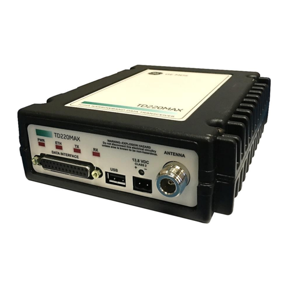
TD220MAX_manual_v11.doc 3 Interfaces 3.1 Data Interface (DB-25) The Data Interface has several ports integrated into one connector: Ethernet, COM1 and COM2 Serial Ports, and GPS signaling. Note that COM3 is connected internally and therefore not available on pins labeled with “COM3.” Notes DB-25 Direction WRT MDS... -
Page 7: Usb
The radio provides a USB Port conforming to version 1.1 of the USB standard. This port is provided for features such as logging STFP messages to text files on a memory stick. Consult GE MDS for information on this feature. The pinout for this connector is given in the table below. -
Page 8: Common Setup Tasks
Putty, connected directly to the TD220X COM1 port via a serial cable. Telnet—Text-based access to the Menu System through a network connection. Firmware images are provided free-of-charge on the MDS Web site at: http://supportcentral.ge.com/products/sup_products.asp?prod_id=181796 05-6906A01 Page 8 of 49 7/31/2014... -
Page 9: Installing Td220X Firmware By Tftp
Starting Information Screen. (See Page 24.) A TFTP server can be found on the MDS web site at: http://supportcentral.ge.com/products/sup_products.asp?prod_id=181796 4.3.3 Upload Procedure To upload a new firmware file (tdx-krmd-X_Y_Z.mpk) into the TD220X unit use the following... -
Page 10: Set Up A Ptp Base Unit
TD220MAX_manual_v11.doc 14. Go to the Maintenance/Tools menu. 15. Verify the Ethernet Link using the Ping utility. 16. Begin sending UDP data. 17. Verify the TX LED illuminates and the radio begins transmitting over the air. 4.5 Set Up a PTP Base Unit If not already done, complete steps from 4.2 above. -
Page 11: Perform Test Polling
TD220MAX_manual_v11.doc 11. Go to the Maintenance/Tools menu. 12. Verify the Ethernet Link using the Ping utility. 13. Ensure at least one base is present in the neighborhood of this radio so that it can detect beacons and synchronize timing. 14. Begin sending UDP data from a polling program. 15. - Page 12 TD220MAX_manual_v11.doc Configure the Base as follows: System Configuration Menu -==========================================================================- A) Timing Source B) STFP Radio ID C) STFP Receive Port 53000 D) STFP Transmit Address x.x.x.x (Note: Use IP address of Poller PC) E) STFP Transmit Port 50000 F) STFP Epoch Size 6 sec G) STFP Slot Delay H) STFP Send OTA Beacon...
- Page 13 Select a letter to configure an item, <ESC> for the prev menu Reboot the Mobile Obtain the TD220X Poller (TD220X_Poller.exe) from GE MDS. In the Poller directory, create or modify the TD220X poller data configuration file (TD220X_Poller.parms) as shown below.
- Page 14 TD220MAX_manual_v11.doc set ::TXparms { { 0 "Type" 8 "00" "RW" } { 1 "Ver" 8 "09" "RW" } { 2 "Radio ID" 32 "00000040" "RW" } { 3 "Radio Cfg Tag" 8 "00" "RW" } { 4 "Timeslot" ts "07" "RW"...
- Page 15 TD220MAX_manual_v11.doc Set up the Poller as shown below, where 10.4.144.100 is replaced with the IP address of your base radio. Note: Set GPS Serial Port to None to prevent the utility opening a serial port. 10. Click Start Polling and observe the message counts and sequence number increment. The test will show 100% success if all messages sent to the base radio were transmitted over the air, received by the mobile radio, and forwarded back to the Poller.
- Page 16 TD220MAX_manual_v11.doc 11. The TX Message tab updates as messages are sent to the base radio. 12. The RX Message tab updates as messages are received from the mobile radio. 05-6906A01 Page 16 of 49 7/31/2014...
- Page 17 TD220MAX_manual_v11.doc 13. The Timeslot Map tab updates as messages are sent and received to show the distribution of messages across the available timeslots. Note: Only 48 timeslots are shown, supporting up to a 6 second epoch. 05-6906A01 Page 17 of 49 7/31/2014...
-
Page 18: Perform Field Survey
TD220MAX_manual_v11.doc 4.8 Perform Field Survey 4.8.1 Set up the Base System Set up a Base radio as above, using either a GPS or PTP timing configuration. Erect a representative antenna system and connect the antenna system to the radio with representative feedline. - Page 19 TD220MAX_manual_v11.doc Notes: The Polling interval should be set to something fairly short to make sure the survey territory is adequately painted, however setting it below 500 ms or so may exceed the transmit duty cycle of the radio and/or overflow the radio’s input buffer and should be avoided. Setting “Stop After (polls)” to zero causes the base Poller to continue transmitting messages indefinitely.
- Page 20 TD220MAX_manual_v11.doc Note: Again, make sure you are authorized to transmit on the TX frequency you configure here. Make sure the transmit power is appropriate for the survey you are undertaking. 2 Watts shown above is the minimum power the radio puts out stand-alone. With an external PA, the radio is set to 2 Watts and the PA is adjusted to obtain the desired transmit power level.
-
Page 21: Set Up The Mobile System
TD220MAX_manual_v11.doc 4.8.2 Set up the Mobile System Set up the Mobile Radio as above, such that it obtains its system timing “OTA” or over the air using beacons from the Base Radio. Obtain a GPS receiver that can output NMEA serial messages to a portable PC for logging purposes. - Page 22 TD220MAX_manual_v11.doc Notes: Set the mobile Poller’s “Stop After (polls)” value to zero to cause it to run until stopped manually. Set the mobile Poller’s “Parse Response” field to “Yes”. 05-6906A01 Page 22 of 49 7/31/2014...
- Page 23 TD220MAX_manual_v11.doc Notes: Make sure the RX Message tab looks like this. This tab is set up via the TD220X_Poller.parms file as shown above. 05-6906A01 Page 23 of 49 7/31/2014...
-
Page 24: Menu Interface
TD220MAX_manual_v11.doc 5 Menu Interface Login with the administrator user name and password 05-6906A01 Page 24 of 49 7/31/2014... - Page 25 TD220MAX_manual_v11.doc When logged in, the Starting Information Screen is displayed. Parameter Description Device Name User-configured name for this radio. Set this from the Device Names menu. IP Address IP Address for this radio. Set this from the IP Networking menu. Device Status “Initializing”...
-
Page 26: Main Menu
TD220MAX_manual_v11.doc 5.1 Main Menu Parameter Description A) Starting Information Returns to the opening menu. Screen B) Network Set the radio’s IP Address, Netmask, and Gateway. Configuration C) System Set the radio’s timing source (GPS/PTP/OTA) and other Configuration application-specific operating parameters. D) Radio Configuration Set the radio’s Frequencies, RF Power Output, External PA Enable and access the Force TX Key function. -
Page 27: Network Configuration Menus
TD220MAX_manual_v11.doc 5.2 Network Configuration Menus Parameter Description A) IP Configuration Access the IP Configuration menu to set the IP Address, Netmask, and Gateway IP Address. B) SNMP Agent Access the SNMP Agent Configuration Menu. Configuration Ethernet Address Displays the hardware MAC address for the Ethernet port. 05-6906A01 Page 27 of 49 7/31/2014... - Page 28 TD220MAX_manual_v11.doc Parameter Description A) IP Address The IP address that this radio will use for its Ethernet interface. B) IP Netmask The subnet mask for the network this radio is part of. C) IP Gateway The IP address of the gateway that will pass traffic from the radio’s subnet to nodes on other networks.
- Page 29 TD220MAX_manual_v11.doc Parameter Description A) SNMP Read SNMP community string used for SNMPv1/SNMPv2c read access. Community This string can be up to 30 alphanumeric characters. B) SNMP Write SNMP community string used for SNMPv1/SNMPv2c write access. Community This string can be up to 30 alphanumeric characters. C) SNMP Trap SNMP community string used for SNMPv1/SNMPv2c trap access.
- Page 30 TD220MAX_manual_v11.doc Parameter Description K) SNMP Trap Manager Specifies an SNMP Manager on the network that traps will be sent L) SNMP Trap Manager Specifies an SNMP Manager on the network that traps will be sent M) SNMP Trap Specifies an SNMP Manager on the network that traps will be sent Manager #4 05-6906A01 Page 30 of 49...
-
Page 31: System Configuration Menu
TD220MAX_manual_v11.doc 5.3 System Configuration Menu Parameter Description A) Timing Source The timing source used by the radio to precisely determine current time and the start of each second. Valid values are Global Positioning System (GPS), Precision Time Protocol (PTP), GPS with PTP fallback, PTP with GPS fallback, and over-the-air (OTA). -
Page 32: Radio Configuration Menu
TD220MAX_manual_v11.doc Timeout asserts an alarm and if configured fails over to the selected alternate timing source. 5.4 Radio Configuration Menu Parameter Description A) Transmit Frequency The initial frequency in the 216.0 to 221.99875 MHz range that the radio uses for over the air transmissions upon booting. Note: STFP messages specify the frequency to be used when transmitting. - Page 33 TD220MAX_manual_v11.doc 05-6906A01 Page 33 of 49 7/31/2014...
-
Page 34: Gps Configuration Menu
TD220MAX_manual_v11.doc 5.5 GPS Configuration Menu Parameter Description A) GPS NMEA Baud This is the Baud Rate used on the radio port to receive NMEA Rate Sentences. B) GPS PPS Polarity Indicates if the TTL PPS Pulse is Active High (Positive Pulse) or Active Low (Negative Pulse). -
Page 35: Ptp Configuration Menu
TD220MAX_manual_v11.doc 5.6 PTP Configuration Menu Parameter Description A) PTP Receive Port This IP Port is used by the radio to receive messages from the PTP grandmaster Clock. B) PTP Transmit This is the IP Address of the PTP Grandmaster Clock to which the Address radio will send PTP messages. -
Page 36: Security Configuration Menu
TD220MAX_manual_v11.doc 5.7 Security Configuration Menu Parameter Description A) Telnet Access If “enabled”, the radio allows users to Telnet to the radio via Ethernet. If “disabled”, users must manage the radio via SNMP or the serial console. B) User Passwords Allows modification of the admin password. F) SNMP Mode This specifies the mode of operation of the SNMP Agent. -
Page 37: Statistics/Logging Menus
TD220MAX_manual_v11.doc 5.8 Statistics/Logging Menus Parameter Description A) STFP Logger Access the STFP Logger menu. B) Wireless Packet Access the Wireless Packet Statistics menu where you can view Statistics the number of messages passed over the air. C) Ethernet Packet Access the Ethernet Packet Statistics menu where you can view Statistics the number of messages passed via Ethernet. - Page 38 TD220MAX_manual_v11.doc Parameter Description A) STFP Log Enable If “enabled”, the radio will send UDP messages to a logging host. B) STFP Log Server The IP address to send UDP messages for logging STFP traffic. C) STFP Log Server The IP port number to send UDP messages for logging STFP traffic. Port 05-6906A01 Page 38 of 49...
- Page 39 TD220MAX_manual_v11.doc Parameter Description Tx Beacons The number of beacon messages transmitted over the air. Beacon messages are messages sent in the first time slot of a second that contain no payload. If a message with payload is sent during the first time slot of a second, it is still used by OTA radios to synchronize time but it is not included in this statistic.
- Page 40 TD220MAX_manual_v11.doc Parameter Description Packets Received The number of packets received over Ethernet. Packet Sent The number of packets transmitted over Ethernet. Bytes Received The number of bytes for all packets received over Ethernet. Bytes Sent The number of bytes for all packets transmitted over Ethernet. Packets Dropped The number of packets that were dropped due to the Ethernet interface being busy.
- Page 41 TD220MAX_manual_v11.doc Parameter Description A) Current Alarms Display a list of the alarms currently active within the radio. B) View Event Log Scroll through the historical list of radio events and alarms. C) Clear Event Log Erase all history of radio events and alarms. D) Send Event Log Begin a TFTP transfer of the historical list of all radio events to the IP Address given by “Event Log Host Address”.
-
Page 42: Device Information Menus
TD220MAX_manual_v11.doc 5.9 Device Information Menus Parameter Description Model The Model Type of the radio. Serial Number The factory-assigned unique radio Serial Number. Uptime The number of elapsed hours, minutes, and seconds since the radio last rebooted. Date The Date from the GPS receiver. Time The Time from the GPS receiver. - Page 43 TD220MAX_manual_v11.doc Parameter Description A) Device Name Free-form field where you can enter a nickname for this radio. B) Contact Free-form field where you can indicate who to contact in case the radio needs service. C) Location Free-form field where you can describe the site at which the radio is installed.
-
Page 44: Maintenance/Tools Menus
TD220MAX_manual_v11.doc 5.10 Maintenance/Tools Menus Parameter Description A) Reprogramming Access the Reprogramming menu where you can upgrade the radio’s firmware. B) Configuration Access the Configuration Scripts menu where you can save and Scripts restore the radio’s configuration to and from a text file via a TFTP server. - Page 45 TD220MAX_manual_v11.doc Parameter Description A) TFTP Host Address The IP address of the TFTP server from which you will download a new firmware image. B) Firmware Filename The file name for the firmware image. This file must exist on the server. C) TFTP Timeout If the radio cannot reach the TFTP server, it waits this long before giving up at each step in the process.
- Page 46 Configuration scripts are used to store and duplicate radio settings. To use this facility, send the configuration file from a radio to the TFTP server. It can then be archived or edited and retrieved from the same or different radios. For more information, contact GE MDS. 05-6906A01...
- Page 47 TD220MAX_manual_v11.doc Parameter Description A) Address to Ping The IP address of the network host to which you will send test messages. B) Count The number of test messages you will send. C) Packet Size The number of Bytes each test message will contain. D) Ping Command the radio to begin the ping test.
-
Page 48: Troubleshooting
TD220MAX_manual_v11.doc 6 Troubleshooting Here are some tips to help resolve issues when operating the TD220X. Symptom Possible Cause Radio is alarmed (PWR LED is flashing) Check the alarm list accessible from the Starting Information Screen. Alarm: GPS PPS Not Available Radio is not receiving a PPS. -
Page 49: Change Log
TD220MAX_manual_v11.doc 7 Change Log Version Date Author Changes 1/17/2011 L. Lowe Initial release for TD220X 1/20/2011 T. Mayo Updated FCC notices Updated power supply current requirements 2/15/2011 T. Mayo Clarified 1PPS input levels. 2/24/2011 T. Mayo ...