Casio IT-9000 Series Service Manual
Hide thumbs
Also See for IT-9000 Series:
- User manual (86 pages) ,
- Quick start manual (75 pages) ,
- User manual (89 pages)
Table of Contents
Advertisement
Quick Links
Advertisement
Chapters
Table of Contents

Related Manuals for Casio IT-9000 Series


Summary of Contents for Casio IT-9000 Series
- Page 1 SERVICE MANUAL HANDHELD TERMINAL IT-9000 MAR. 2012 Ver. 8 : Mar. 2018...
- Page 2 • Other company and product names are generally registered trademarks or trademarks of the respective companies. Information in this document is subject to change without advance notice. CASIO Computer Co., Ltd. makes no representations or warranties with respect to the contents or use of this manual and specifi cally disclaims any express or implied warranties of merchantability or fi...
-
Page 3: Table Of Contents
IT-9000 CONTENTS 1. GENERAL ........................1 1-1. Confi guration by Model ........................1 1-2. Options ............................... 3 2. SPECIFICATION ......................4 2-1. System Requirements ........................4 2-2. Part Names and Functions ......................14 2-3. Dimensions/Weight ......................... 17 2-4. Environmental Performance ......................18 3. - Page 4 IT-9000 SAFETY PRECAUTIONS Congratulations upon your selection of this CASIO product. Be sure to read the following Safety Precautions before use. Your neglect or avoidance of the warning and caution statements in the subsequent pages causes the danger of fi re, electric shock, malfunction and damage on the goods as well as personal injury.
- Page 5 IT-9000 Interference with the Operation of Other Equipment (Using Wireless Data Communication) • Keep your Handheld Printer Terminal at least 22 centimeters (8 ”) away from anyone wearing a pacemaker. Radio waves emitted by the Handheld Printer Terminal can aff ect the operation of a pacemaker.
- Page 6 Immediately rinse it off with clean tap water and then consult a physician. • Danger of explosion if the battery pack is incorrectly replaced. Replace only with same or equivalent type recommended by CASIO. Dispose of used batteries according to the CASIO instruction.
- Page 7 Backup of All Important Data • Note that CASIO Computer Co., Ltd. shall not be held liable to you or any third party for any damages or loss caused by deletion or corruption of data due to use of the Handheld Printer Terminal, malfunction or repair of the Handheld Printer Terminal or its peripherals, or due to the batteries going dead.
-
Page 8: General
IT-9000 1. GENERAL 1-1. Confi guration by Model Y Model-A Roll Paper Product Name Camera W-LAN Scanner Size SD Slot Slot IT-9000-E 11b/g 80 mm IT-9000-05E 11b/g 80 mm IT-9000-GE ... - Page 9 IT-9000 Y Model-C Roll Paper Product Name Camera W-LAN Scanner Size SD Slot Slot IT-9000-E-C 11b/g/n 80 mm IT-9000-05E-C 11b/g/n 80 mm IT-9000-GE-C 11b/g/n 80 mm ...
-
Page 10: Options
IT-9000 1-2. Options Product Name Description HA-L60IO USB Cradle HA-L62IO Ethernet Cradle HA-G32DCHG Dual Battery Charger HA-L30CHG Cradle-type Battery Charger HA-L35CHG Car Mounted-type Battery Charger (The car adaptor accompanies to HA-L35CHG.) AD-S42120B-N* AC Adaptor (without AC-CORD) AD-S42120C-N5 AC Adaptor (without AC-CORD) HA-G20BAT Battery Pack AC-CORD-EU... -
Page 11: Specification
IT-9000 2. SPECIFICATION 2-1. System Requirements Y Model-A and B Item Specifi cations Marvell ® Xscale Processor PXA320 624 MHz Microsoft Windows Embedded CE 6.0 R3 ® ® Microsoft ® Windows ® Mobile 6.5 Professional Microsoft Windows Mobile 6.5 Classic ®... - Page 12 IT-9000 Item Specifi cations 2D Scanner Readable Symbologies UPC-A, UPC-E, EAN8 (JAN8), EAN13 (JAN13), Codabar (NW-7), (1D) Code39, Interleaved2of5 (ITF), MSI, Code93, Code128 (GS1-128 (EAN128)), Code11, IATA, GS1 DataBarOmnidirectional (RSS-14), GS1 DataBarLimited (RSS Limited), GS1 DataBar Expanded (RSS Expanded), Code32, GS1 DataBar Truncated (RSS-14 Truncated), ISBT Readable Symbologies PDF417, Micro PDF, CODE49, Composite,...
- Page 13 IT-9000 Y Model-C and D Item Specifi cations Marvell Xscale Processor PXA320 806 MHz ® Microsoft ® Windows ® Embedded CE 6.0 R3 Microsoft Windows Embedded Handheld 6.5 Professional ® ® Memory 256 MB FlashROM Windows CE: 512 MB (User area: 340 MB) 2D Scanner Principle CMOS imager, 832 ×...
- Page 14 IT-9000 Item Specifi cations W-LAN Type of Emission Spread spectrum communication system (802.11b/g/n) Spread Spectrum 802.11b: DSSS (Direct Sequence Spread Spectrum) method Modulation 802.11g/n: OFDM (OrthogonalFreq uencyDiv isionMultip lexing) Modulation Method BPSK, QPSK, CCK, 16QAM, 64QAM ITU code 802.11b: D1D, G1D (Emission Identifi...
- Page 15 IT-9000 Y Common to all models Item Specifi cations Display System Blanview TFT (Ortus Technology Co.,Ltd.) Display Size 3.7 inch No. of Dots 480 (horizontal) × 620 (vertical) (VGA) * When an OS is for CE, QVGA is settable. Dot Pitch 0.117 mm (vertical) ×...
- Page 16 IT-9000 Item Specifi cations Communication Function Audio, Packet data Data Packet GPRS (General Packet Radio Service) Transmission • Multi-slot class 12 • Mobile station class B • Coding scheme CS1-4 EDGE (Enhanced Data Rates for GSM Evolution)/ EGPRS (Enhanced GPRS) •...
- Page 17 IT-9000 Item Specifi cations W-CDMA Radio Frequencies IT-9000-G05E/GE/GMC25E/GMC30E/G25E/G20E/GC25E/GM35E/GM30E IT-9000-GE-D/G05E-D/GMC25E-D/G20E-D/G25E-D/GC25E-D/GMC30E-D/GM30E-D • Band I: UMTS2100 Uplink: 1920 ~ 1980 MHz Downlink: 2110 ~ 2170 MHz • Band II: UMTS1900 Uplink: 1850 ~ 1910 MHz Downlink: 1930 ~ 1990 MHz • Band V: UMTS850 Uplink: 824 ~ 849 MHz Downlink: 869 ~ 894 MHz •...
- Page 18 IT-9000 Item Specifi cations Carrier Frequency 13.56 MHz ± 7 kHz Antenna Magnetic fi eld type loop antenna Magnetic Field Output magnetic fi eld strength when contacting the case: 1.5 A/m or more * Based on measuring method of ISO10373-6 (JIS X 6305-6) Output magnetic fi...
- Page 19 IT-9000 Item Specifi cations SD Card Slot SDHC/SDIO card supported Expansion Port Use by connecting a trigger glip Host Transmission rate: Full speed (12 Mbps), Low speed (1.5 Mbps) External output power: 5 V/500 mA Client Transmission rate: Full speed (12 Mbps) Camera Eff...
- Page 20 IT-9000 <Power> Item Specifi cations Remarks Main Battery Lithium ion battery Backup Battery Rechargeable lithium battery × 1 Built-in type Operating Time Approx. 20 hours JEITA A mode/ Normal temperature/ Brand-new battery Approx. 16 hours JEITA D mode/ Normal temperature/ Brand-new battery WAN Standby: Approx.
-
Page 21: Part Names And Functions
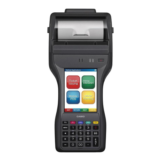
IT-9000 2-2. Part Names and Functions [ NOTE ] External form varies with models. <Top> <Left> <Front> <Right> <Back> <Bottom> – 14 –... - Page 22 IT-9000 Name Description Printer Prints on a roll paper installed. Splash Protect Cover Protects printer from splash. When printing, open the cover by sliding it. Power Key Turns the power on and off . Indicator 2 Flashes blue when operating via Bluetooth or orange when operating via W-LAN.
- Page 23 IT-9000 <Key Layout> Name Description Function Keys Used to start application programs registered beforehand. C (Clear) Key Used to clear the whole entry at a time. BS (Backspace) Key Delete one character to the left of the cursor. ENT (Enter) Key Used to enter the input value.
-
Page 24: Dimensions/Weight
IT-9000 2-3. Dimensions/Weight Product Name Dimensions (D × W × H) Weight IT-9000-E IT-9000-E-B IT-9000-05E Approx. 112 × 247 × 60 mm Approx. 590 g IT-9000-05E-B IT-9000-E-C IT-9000-05E-C IT-9000-GE IT-9000-GE-B IT-9000-GE-D IT-9000-G05E Approx. 112 × 247 × 60 mm Approx. 615 g IT-9000-G05E-B IT-9000-GE-C IT-9000-G05E-D... -
Page 25: Environmental Performance
IT-9000 Product Name Dimensions (D × W × H) Weight IT-9000-GMC30E IT-9000-GMC30E-B Approx. 112 × 286 × 66 mm Approx. 685 g IT-9000-GMC30E-C IT-9000-GMC30E-D IT-9000-GM35E IT-9000-GM30E IT-9000-GM30E-B Approx. 112 × 286 × 66 mm Approx. 680 g IT-9000-GM30E-C IT-9000-GM30E-D *1: Excluding protruding parts. *2: Including battery pack but excluding roll paper. -
Page 26: Technical Information
IT-9000 3. TECHNICAL INFORMATION 3-1. Wiring Diagram LNA PCB FPC-SENSOR WAN Antenna Speaker POWER PCB SUB PCB FPC- GPS Antenna POWER WAN Module Reset Switch FPC-NFC Controller W-LAN Bluetooth Bluetooth Module Antenna Module NFC PCB 100 pin W-LAN Antenna FPC-NFC-ANT 100 pin Printer SD Card 2... -
Page 27: System Diagram
IT-9000 3-2. System Diagram IT-9000 W-LAN Module IEEE802.11b/g Products IEEE802.11b/g Access Point Mobile Phone Network WAN Module GSM/W-CDMA, GPS Satellite Bluetooth Module Bluetooth Products (Ver2.0+EDR) Headset, Printer, PC, IT-9000 ISO14443 Type A, ISO14443 Type B, FeliCa, ISO15693 USB Host USB Device USB Client USB Port USB Cradle... -
Page 28: Reset
IT-9000 4. RESET Performing a reset causes all unsaved RAM data to be lost that are in mid-course of inputting and editing, but data and settings that are already stored in the FlashROM should be unaff ected. Perform a reset to restore normal operation whenever the Handheld Printer Terminal operates abnormally due to misoperation or some other reason. -
Page 29: Hardware Test/Setting
IT-9000 5. HARDWARE TEST/SETTING 5-1. General In this chapter, how to check the hardware of IT-9000 is explained. The general fl ow to start up the test program is as follows: Prepare equipment required. Obtain the test program Diag_It9000.zip (Download from website.) Unzip Diag_It9000.zip and copy it to a SD card. -
Page 30: Initial Settings
IT-9000 5-2. Initial Settings [ NOTE ] When the MAIN-UNIT, WAN/GPS-MODULE, or NFC-ASSY is replaced with a new one, be sure to perform the following settings in the order indicated by “No.”. [ NOTE ] Be sure to perform the settings before proceeding to the function test. Item Model Type Remarks... - Page 31 IT-9000 Operation Display Test Details Press the “ENT” key or tap Check that the message “Model/ “[ENT] OK”. ID Setting Succeeded” is shown. Tap “ok” in the “Success” IT-9000 will automatically reset. dialog box, and then “[Fn+CLR] END”. Start up “IDCHK_PY011.exe” under \\My Device\FlashDisk\ DIAG to see that the product ID is correctly registered.
- Page 32 IT-9000 WAN settings (For WAN type only) [ NOTE ] When replacing the WAN/GPS-MODULE with a new one, be sure to perform the following procedure. Operation Display Test Details Start up “WANModuleSetting. exe” under \\My Device\ FlashDisk\DIAG. The screen on the right appears.
- Page 33 IT-9000 Upgrading NFC fi rmware [ NOTE ] When replacing the NFC-ASSY with a new one, be sure to perform the following procedure. Operation Display Test Details Start up “NFCWriteFirm.exe” The current version and a new under \\My Device\FlashDisk\ version for upgrading appear. DIAG\NFCFirmTool.
-
Page 34: Function Test
IT-9000 5-3. Function Test 5-3-1. List of Test Items [ NOTE ] Degree of importance: A: Essential (A): Essential when the part is replaced B: As required [ NOTE ] “ALL TEST MENU-X” denotes the test program menu, while “Special Test (testing without using the test programs)”... - Page 35 IT-9000 Test Item Degree Model Type Remarks ALL TEST MENU-7 [3] NFC Tag ID Read Common RFID tag [8] SD2 Write Protect 2nd SD SD card [9] SAM Read Common SAM card for testing ALL TEST MENU-8 [2] Printer (all check) Common Roll paper for testing DC power supply unit, DC voltmeter,...
- Page 36 IT-9000 5-3-2. Test Equipment The following shows the major equipment used for function test. [ NOTE ] For equipment used for the special test, see respective test items. RFID tag (85 × 54 Roll paper for testing External expansion I/F test PCB SD/SDHC card Test Object...
- Page 37 IT-9000 5-3-3. Installing the Test Program and Test Data [ NOTE ] The test program and test data used for the special test are also installed. [ NOTE ] In the special test, it is required to install some software and fi les on PC. For details, see the respective test items.
- Page 38 IT-9000 (4) Install the SD card in which the test program is written in test object IT-9000. (5) Turn ON IT-9000 and execute “SetFactoryTool.exe” under \\My Device\SD Card using Explorer. (6) When “It copy a Factory Tool ..” is shown, tap “Yes”. (7) The test program (DIAG folder) is copied under “FlashDisk”, and then IT-9000 automatically restarts.
- Page 39 IT-9000 5-3-5. Start-up of the Test Program [ NOTE ] For the special test, see respective items. Execute “DiagPY011.exe” under \\My Device\FlashDisk\DIAG using Explorer. The top menu screen is displayed as shown. PY-011 Test Program Ver x.xx Top MENU [1].All Test Displays all test items.
- Page 40 IT-9000 5-3-7. menu screen transition diagram The following shows the menu transition diagram when “[1] All Test” is selected in the top menu. [ NOTE ] For the special test, see respective items. [ NOTE ] When “[2] Test limited to model (Auto judge)” is selected, product ID is displayed at the title part and test items dedicated to that model are shown.
- Page 41 IT-9000 5-3-8. Test Procedures ALL TEST MENU-1 [1] RAM Operation Display Test Details Select “[1].RAM” from The increment data is written to, MENU-1 screen. read from and then compared with the maximum possible RAM area. If OK: The screen returns to the menu screen.
- Page 42 IT-9000 [3] EEPROM Operation Display Test Details Select “[3].EEPROM” from The increment data is written to, MENU-1 screen. read from and then compared with the maximum possible EEPROM area. If OK: The screen returns to the menu screen. If any problem: The failed addresses, correct data and wrong data are displayed.
- Page 43 IT-9000 [6] Battery Cover SW (Standard) Battery pack cover lock switch (Right side) Operation Display Test Details Select “[6].Battery Cover SW Automatically detects if the (Standard)” from MENU-1 battery pack cover is open. screen. If OK: When the screen on the right Next screen appears.
- Page 44 IT-9000 [7] Touch Panel Operation Display Test Details Select “[7].Touch Panel” from Touch the cursors at 4 corners MENU-1 screen. (white portions) with a stylus in any order. The touched cursor changes to black. After touching all cursors to change them into black, the test result is judged as OK and the screen returns to the menu screen.
- Page 45 IT-9000 ALL TEST MENU-2 [3] LCD Operation/Test Details Select “[3].LCD” from MENU-2 screen. Pressing the “ENT” key changes the pattern screens in sequence. After 8 pattern screens have been displayed, manual judgment screen is displayed. If the patterns are displayed correctly: Press the “1” key to return to the menu screen. If any failure is found on the display: Press the “0”...
- Page 46 IT-9000 [4] LCD Backlight Operation Display Test Details Select “[4].LCD Backlight” The backlight brightness is from MENU-2 screen. maximized. Each time you press the “ENT” key, the brightness level changes from “maximum” to “minimum”, and then to “standard”. When you press it once again, the judgment screen appears.
- Page 47 IT-9000 [6] Operation & Charge LED Operation/Test Details Select “[6].Operation LED & Charge LED” from MENU-2 screen. Each time the “ENT” key is pressed, the lighting pattern of the indicators and the display pattern of the LCD successively change as follows. After 5 kinds of lighting and display patterns have appeared, the manual judgment screen is displayed.
- Page 48 IT-9000 [8] Speaker Operation/Test Details Select “[8].Speaker” from MENU-2 screen. Speaker mode starts and a tone (3 kHz, 0.3sec. duration) is emitted in three volume levels, “small”, “medium” and “large” in that order. This loop is repeated two times. Then buzzer mode starts and a buzzer tone (10 kHz, 0.3sec. duration) is emitted in three volume levels, “small”, “medium”...
- Page 49 IT-9000 ALL TEST MENU-3 [1] LED Flash (Camera type only) Operation Display Test Details Select “[1].LED Flash” from When the “ENT” key is pressed, MENU-3 screen. the LED lights up. When it is pressed again, the LED goes out. Then, the manual judgment screen appears.
- Page 50 IT-9000 [4] Audio (Rec & Rep) Operation/Test Details Select “[4].Audio(Rec&Rep)” from MENU-3 screen. As recording stats, talk over the microphone of IT-9000. Recorded sound is played back and output from the speaker. Then, the manual judgment screen appears. If sound is output (OK): Press the “1” key to return to the menu screen. If sound is not output correctly (Failure): Press the “0”...
- Page 51 IT-9000 [0] Camera (Camera type only) Operation Display Test Details Select “[0].Camera” from Capturing image is displayed MENU-3 screen. on the preview screen. Also, the manual judgment conditions are displayed. If displayed properly (OK): Press the “1” key to return to the menu screen.
- Page 52 IT-9000 ALL TEST MENU-4 [1] Cradle I/F (USB Host) Operation Display Test Details Select “[1].Cradle I/F (USB A test fi le (approx. 64 KB) is Host)” from MENU-4 screen. written, read and compared for the USB memory. Set IT-9000 and USB memory to the USB cradle.
- Page 53 IT-9000 [9] ADC-Sensor Operation Display Test Details Select “[9].ADC-Sensor” from Judges automatically if the AD- MENU-4 screen. converted value is within the following range or not for each item. Main battery voltage (ON) (MUX0): Between 6.0 to 8.5 V Main battery voltage (OFF) (MUX1): Between 6.0 to 8.5 V Backup battery (MUX2):...
- Page 54 IT-9000 ALL TEST MENU-5 [2] miniUSB I/F (USB Host) Operation Display Test Details Select “[2].mini USB I/F(USB A test fi le (approx. 64 KB) is HOST)” from MENU-5 screen. written, read and compared for the USB memory. Connect IT-9000 and USB memory with the USB cable If OK: (for host).
- Page 55 IT-9000 [4] Current - Charge (AC Adapter) [ NOTE ] Before starting test, set a battery pack that is not fully charged (7.8 V or less) to IT-9000, and then supply power to IT-9000 from the AC adaptor. Operation Display Test Details Select “[4].Current - Automatically judges if the...
- Page 56 IT-9000 ALL TEST MENU-6 [1] Current - Run mode Operation Display Test Details Select “[1].Current - Run Automatically judges if the Mode” from MENU-6 screen. current value is within 100 to 200 mA. For Model-C: 80 to 200 mA If OK. The screen returns to the menu screen.
- Page 57 IT-9000 [7] Current - W-LAN Operation Display Test Details Select “[7].Current - W-LAN” Automatically judges if the from MENU-6 screen. current value is within 150 to 250 mA. If OK. The screen returns to the menu screen. If out of range (Failure): An error indication is displayed.
- Page 58 IT-9000 ALL TEST MENU-7 [3] NFC Tag ID Read RFID tag (85 × 54 mm) 70 mm Do not use a metal stand. Operation Display Test Details Select “[3].NFC Tag ID Read” Automatically checks the NFC from MENU-7 screen. fi rmware version and judges if a combination of the NFC fi...
- Page 59 IT-9000 [8] SD2 Write Protect (2nd SD type) [ NOTE ] Be sure that the lock switch of the SD card is not set to the write-protect position, and then insert the SD card into the 2nd SD card slot of IT-9000. Operation Display Test Details...
- Page 60 IT-9000 [9] SAM Read [ NOTE ] Before starting test, install SAM cards to be tested in the SAM card slots. [ NOTE ] Do not install a SAM card in the SIM card slot by mistake. [ NOTE ] The number of SAM cord slots diff ers depending on the models. SAM SAM SAM Operation Display...
- Page 61 IT-9000 ALL TEST MENU-8 [2] Printer (all check) [ NOTE ] Before starting test, set roll paper for testing to IT-9000 while aligning it with the paper cutter. Be sure that markers and barcodes are printed on the back side of the roll paper. Operation Display Test Details...
- Page 62 IT-9000 [3] Current - Printer [Preparation] (1) Open the battery pack cover and remove the battery pack. (2) Connect equipment as shown below. (3) Set the voltage control of the DC power supply at a minimum position, and then turn ON its power.
- Page 63 IT-9000 [4] Splash Cover OPEN CLOSE Operation Display Test Details Select “[4].Splash Cover” from MENU-8 screen. When roll paper is set, “Status” display changes from “PAPER_END” to “NORMAL”. After confi rming the display “NORMAL”, close the splash cover. After confi rming that the cover Detects open/close of the close status is detected, open splash cover and automatically...
- Page 64 IT-9000 [5] MCR Read (MCR type only) [ NOTE ] Be careful that the magnetic card for testing is dedicated for IT-9000. So, the magnetic card for other handheld terminals cannot be used for IT-9000. Operation Display Test Details Select “[5].MCR Read” from Automatically judges the read MENU-8 screen.
- Page 65 IT-9000 Special Test Image Scanner Demo (2D type only) Operation Display Test Details Select “Start” – “Image The read image/data is Scanner Demo”. displayed on the screen. Check that the image/barcode Six menu (Scan barcode, symbol(s) are read correctly. Scan several barcodes, Capture image, Scan target Tap “Exit”...
- Page 66 IT-9000 Operation Display Test Details Select “Basic”, “WLAN” or “Detail Settings” tab. Then, input “SSID”, “IP address”, etc. of the target access point. Select “Start” – “NetSearch” Carry out wireless test using in that order. “Ping” and “Signal” functions. Tap “Tools” and then select Check if the test results are “Ping”...
- Page 67 IT-9000 Cradle I/F (USB-Client) <Required equipment> Connect equipment as follow. USB cable (to connect cradle to PC) Test Object Ethernet cradle AC adaptor & AC cord * Pre-installation of the Microsoft ActiveSync/Windows Mobile Device Center is required. Depends on OS to be used. ActiveSync: for Windows XP or earlier, Windows Mobile Device Center: for Windows Vista or later <Preparation of you PC>...
- Page 68 IT-9000 miniUSB I/F (USB-Client) <Required equipment> Connect equipment as follow. Test Object USB cable (for client) * Pre-installation of the Microsoft ActiveSync/Windows Mobile Device Center is required. Depends on OS to be used. ActiveSync: for Windows XP or earlier Windows Mobile Device Center: for Windows Vista or later <Preparation of you PC>...
- Page 69 IT-9000 Bluetooth Class2 [ NOTE ] Install the test program in the opponent IT-9000 before starting test. [ NOTE ] Set a distance between the test object IT-9000 and the opponent IT-9000 to 3 m. Test Object Opponent Operation/Test Details Display Opponent IT-9000: Start up “BTServer.exe”...
- Page 70 Select “Start” – “Settings” – “Connections” – “WAN Settings” in that order. In the WAN Setting screen, select “Power” tab. Check “CASIO WAN Management”, and tap “Apply” button. Select “Start” – “Settings” – Check if “Phone” is set to “On”.
- Page 71 IT-9000 <Checking by information display> Operation Display Test Details Select “Start” – “Settings” – Check if information on WAN and SIM card is displayed. “Connections”– “WAN Settings” in that order. Select “Identifi cation” tab. Select “Status” tab. Check if electric-wave receiving signal strength is displayed in “RSSI”.
- Page 72 IT-9000 Operation Display Test Details Tap “End” to end the call. GPS (WAN type only) [ NOTE ] Insert the SIM card into the SIM card slot before starting test. <Preparation> Operation Display Test Details Select “Start” – “Settings” – “Connections” – “WAN Settings”...
- Page 73 IT-9000 <Checking by information display> Operation Display Test Details Select “Start” – “GPS Displays the information of the Information” in that order. satellite from which the signal is being received. Select “Status” tab. Quality: [ NOTE ] Displays the targeted If GPS information is not positioning.
-
Page 74: Disassembly And Reassembly
IT-9000 6. DISASSEMBLY AND REASSEMBLY 6-1. Precautions before disassembling parts • When reassembling the parts, reverse the disassembly procedures. If “note(s) on reassembling” is stated, be sure to follow it. • Use the right screwdriver according to the screw diameter. •... -
Page 75: L-Case-Unit/L-Case-Assy
IT-9000 6-2. L-CASE-UNIT/L-CASE-ASSY (1) Remove the following parts from IT-9000. Battery Pack, SIM Card, SAM Card, SD Card (2) Undo 12 screws (S2). [ NOTE ] Y-shaped head screws are used. [ NOTE ] For non-MCR type models, undo 8 screws (S2). MCR model (3) Remove the L-CASE-UNIT/L-CASE-ASSY. - Page 76 IT-9000 (4) Parts structure of L-CASE-UNIT/L-CASE-ASSY L-CASE-UNIT VIBRATION-MOTOR L-CASE-ASSY RST-COVER SCREW (S6) SD-CAP-ASSY HOOK-L/BATTERY-PY011 USB-CAP SCREW (S6) HOOK-R/BATTERY-PY011 [ Notes on reassembling ] When the L-CASE-UNIT/L-CASE-ASSY is replaced with a new one, attach the following parts as they are not included in the new one. •...
-
Page 77: I-Case-Unit
IT-9000 6-3. I-CASE-UNIT 6-3-1. I-CASE-UNIT (1) Undo 5 screws (S3). [ NOTE ] For non-MCR type models, undo 3 screws (S3). Screws (S3) CN (Trigger) MCR model W-LAN Antenna GPS Cable FPC (2D) CN (KEY-UNIT) WAN Antenna FPC (Touch Panel) FPC (NFC) FPC (PW-UNIT) CN (Trigger) - Page 78 IT-9000 [ Notes on reassembling ] When assembling the I-CASE-UNIT, be careful not to catch the cables. (1) Pass 2 FPCs through the slit. [ NOTE ] To make it easier, use tweezers. FPC (Touch Panel) FPC (KEY-UNIT) Pass 2 FPCs through the slit in the I-CASE. (2) Assemble the I-CASE-UNIT while confi...
- Page 79 IT-9000 [ Notes on reassembling ] After assembling the I-CASE-UNIT, stick the tapes. GPS Cables FPC (NFC) FPC (PW-UNIT) [ Notes on reassembling ] For 2D models (1) Peel off the release paper from the 2D-SPACER and stick the 2D-FPC to the U-CASE. (2) Stick the tape (1 place).
- Page 80 IT-9000 [ Notes on reassembling ] For the camera-equipped model (Model-C), attach the tape. Core Sheet – 73 –...
- Page 81 IT-9000 6-3-2. I2-CASE-ASSY [ Major parts ] I2-CASE, SUP-UNIT, SUB-BATTERY (1) Release the connector lock and remove the FPC (1 place). (2) Disconnect the connectors (2 places). (3) Undo 3 screws (S8). (4) Remove the WANCAP-UNIT. [ NOTE ] For non-WAN type models, remove the SBAT-HOLDER. CN (SUB-BATTERY) Screws (S8) WANCAP-UNIT...
- Page 82 IT-9000 [ Notes on reassembling ] When replacing the I2-CASE, perform the following procedure. (1) Stick double-sided tapes (2 places). (SBAT-D-TAPE, CAP-TAPE) (2) Stick the EXT-SPACER. CAP-TAPE SBAT-D-TAPE EXT-SPACER (3) SHIELD-TAPE 1. Stick the SHIELD-TAPE by aligning it with the positioning pins. 2.
- Page 83 IT-9000 6-3-3. BAT-UNIT, LCD-UNIT BAT-UNIT (1) Disconnect the connector (1 place). (2) Undo 2 screws (S3). (3) Remove the BAT-UNIT. [ NOTE ] It is stuck with double-sided tape. LCD-UNIT [ Major parts ] LCD-MODULE, LCD-HOLDER, COIL-SPRING (1) Release the connector lock and remove the FPC (1 place). (2) Remove the LCD-UNIT.
- Page 84 IT-9000 6-3-4. EXT-UNIT, CAM-HOLDER, CAMERA-ASSY EXT-UNIT (1) Remove the EXT-UNIT. CAM-HOLDER (1) Remove the CAM-HOLDER. CAMERA-ASSY (1) Release the connector lock and remove the FPC (1 place). (2) Remove the CAM-HOLDER. (3) Remove the CAMERA-ASSY. CAM-HOLDER EXT-UNIT [ Notes on reassembling ] When replacing the CAM-HOLDER, stick double-sided tape as shown.
- Page 85 IT-9000 6-3-6. SUB-UNIT (For WAN/GPS type) [ Major parts ] LNA-UNIT, WAN/GPS-MODULE, SUB-UNIT, WLAN-UNIT (1) Disconnect the GPS cable. (2) Undo 2 screws (S3). LNA-UNIT (3) Remove the LNA-UNIT and disconnect the connector (1 place). Screws (S3) GPS CABLE CN (SUB-UNIT) [ Notes on reassembling ] (1) Connect the cable to the LNA-UNIT.
- Page 86 IT-9000 (4) Undo 7 screws (S3, S10 and S13). (5) The following parts can be disassembled. Screws (S10) Screws (S13) Screws (S3) WAN-CN-PLATE GPS CABLE WAN ANTENNA SUB-FPC-UNIT SUB-UNIT WAN/GPS MODULE W-LAN ANTENNA – 79 –...
- Page 87 IT-9000 [ Notes on reassembling ] WAN ANTENNA (1) Pass the LNA-PW-CABLE through the hole in the WAN antenna. (2) When replacing the WAN antenna, stick the GSM-SPACER. GSM-SPACER [ Notes on reassembling ] WAN/GPS-MODULE, GPS CABLE There are two types of WAN/GPS-MODULE as follows. WAN/GPS-MODULE Model Type MC8795V...
- Page 88 IT-9000 6-3-7. MAIN-UNIT (1) Turn over the MAIN-UNIT. (2) Release the connector lock and disconnect the FPC (1 place). (3) Remove the MAIN-UNIT. MAIN-UNIT [ Notes on reassembling ] Insert the MAIN-UNIT into the under part of the cut ribs (2 places). 6-3-8.
- Page 89 IT-9000 6-3-9. I-CASE-SUBASSY [ Notes on reassembling ] • I-CASE-SUBASSY diff ers between the 80-mm Printer and the 82-mm Printer. • Attach the SPACER-PRINTER for the 80-mm Printer. SPACER-PRINTER • When the I-CASE-SUBASSY is replaced with a new one, attach the following parts to the replaced one.
-
Page 90: U-Case-Unit
IT-9000 6-4. U-CASE-UNIT 6-4-1. PR-COVER-UNIT (1) Undo 2 screws (S1). (2) Remove the PR-COVER-UNIT. Screws (S1) PR-COVER-UNIT 6-4-2. PW-UNIT, KEY-UNIT, PRINTER-CUUTER/ASSY [ Major parts ] PW-UNIT, PW-SUBASSY, KEY-UNIT, KEY-SUBASSY, PEINTER-CUTTER/ASSY PW-UNIT (1) Remove the SCREW-PROTECT. (2) Undo 4 screws (S8). (3) Remove the PW-UNIT and PW-SUBASSY. - Page 91 IT-9000 6-4-3. TR-UNIT (1) Remove the TR-PLATE. (2) Remove the TR-UNIT. (3) Remove the TR-SUBASSY. [ NOTE ] The TR-SUBASSY is stuck with double-sided tape. TR-PLATE TR-UNIT TR-L-SUBASSY TR-R-SUBASSY 6-4-4. NFC-ASSY (1) Release the connector lock and disconnect the FPCs (2 places). (2) Undo 2 screws (S8).
- Page 92 IT-9000 6-4-5. NFC-ANT-ASSY, 2D-ASSY (1) Undo 2 screws (S3) and remove the NFC-ANT-ASSY. (2) Undo 3 screws (S3) and remove the 2D-ASSY. NFC-ANT-ASSY Screws (S3) 2D-ASSY Screws (S3) 2D-PLATE NFC-ANT-ASSY 2D-ASSY – 85 –...
- Page 93 IT-9000 6-4-6. MCR (1) Undo 4 screws (S3, S7). (2) Remove the MCR-U2-CASE. (3) Disconnect the connector (1 place). Connector Screws (S7) MCR-U2-CASE Screws (S3) (4) Undo 2 screws (S7). (5) Remove the MCR. [ NOTE ] The cable is stuck with double-sided tape. [ NOTE ] After removing the MCR, clean any remaining of double-sided tape.
- Page 94 IT-9000 (6) Undo 1 screw (S3) and remove the MCR-PCB-HOLDER. (7) Release the connector lock and disconnect the FPC ( 1 place). MCR-PCB-HOLDER FPC-MCR Screw (S3) [ Notes on reassembling ] When replacing the MCR, perform the following procedure. (1) Assemble the SPACER-MCR on the MCR. (2) Stick double-sided tape (MCR-TAPE).
- Page 95 IT-9000 (3) Arrange the shape of the MCR cable at 2 places. [ NOTE ] While holding the calble so that its contacts can be seen, arrange the shape of the calbe to be in parallel with the clear plate, as shown below. [ NOTE ] During arranging, pay attention so as not to damage the adhisive part of the clear plate.
-
Page 96: Exploded View / Parts List
The numbers in the item column correspond to the same numbers in exploded view. MARKS: Q: Quantity used per unit R: Rank A: Essential B: Stock recommended C: Less recommended X: No stock recommended Refer the latest "Parts Price Code" at "PARTS FINDER" on the Casio Service WEB site (https://www.servicecasio.com). — 89 —... -
Page 97: Exploded View (It-9000)
IT-9000 7-1. EXPLODED VIEW (IT-9000) 7-1-1. FINAL-ASSY 2 PR-COVER-UNIT 7-1-2. UPPER-CASE Tape (WLAN-Antenna) Tape (2D) Tape (GPS-Cable) GPS-Cable 7-1-3. INNER-CASE 7-1-4. I2-INNER-CASE Tape (NFC-Cables) Tape (GPS-Cable) Tape (Connector) Tape (Ferrite Core NFC-Cable & Cables) Double-sided tape (Ferrite Core) Ferrite Core (2D-Cable) Tape (Ferrite Core) - Page 98 IT-9000 7-1-2. UPPER-CASE 26-6 26-4 26-5 26-3 26-7 MCR type 26-1 26-2 Tape (2D-Cable) Tape (Connector) — 91 —...
- Page 99 IT-9000 7-1-3. INNER-CASE Tape (Connector) WAN type Tape (Cables) Tape (Connector) OTHER type 2nd SD type WAN type OTHER type 7-1-4. I2-INNER-CASE WAN type OTHER type 87-1 — 92 —...
- Page 100 IT-9000 7-1-4. I2-INNER-CASE Gasket Double-sided tape — 93 —...
-
Page 101: Lower-Case
IT-9000 7-1-5. LOWER-CASE 1 LOWER-CASE-UNIT (Model-A) LOWER-CASE-ASSY (Model-A, Model-B, Model-C, Model-D) 110 LOWR-CASE-ASSY 1-1 LOWER-CASE-UNIT — 94 —... -
Page 102: Bundled Items
IT-9000 7-1-6. BUNDLED ITEMS 80 mm Paper Width Adjuster 58 mm Paper Width Adjuster Neck Strap Stylus Holder Neck Strap Rings Stylus Hand Strap — 95 —... -
Page 103: Parts List (It-9000)
IT-9000 7-2. PARTS LIST (IT-9000) 7-2-1. Model-A 1: IT-9000-E 4: IT-9000-G05E 7: IT-9000-25E 10: IT-9000-GC25E 13: IT-9000-GMC30E 2: IT-9000-05E 5: IT-9000-GMC25E 8: IT-9000-G20E 11: IT-9000E-MC25E 14: IT-9000-GM35E 3: IT-9000-GE 6: IT-9000-20E 9: IT-9000-G25E 12: IT-9000E-C25E 15: IT-9000-GM30E Q'ty Item Part No. Part Name Descriptions FINAL-ASSY... - Page 104 IT-9000 1: IT-9000-E 4: IT-9000-G05E 7: IT-9000-25E 10: IT-9000-GC25E 13: IT-9000-GMC30E 2: IT-9000-05E 5: IT-9000-GMC25E 8: IT-9000-G20E 11: IT-9000E-MC25E 14: IT-9000-GM35E 3: IT-9000-GE 6: IT-9000-20E 9: IT-9000-G25E 12: IT-9000E-C25E 15: IT-9000-GM30E Q'ty Item Part No. Part Name Descriptions 10428664 TAPE/CORE RJC506478-001 10415569 LABEL/RATING...
- Page 105 IT-9000 1: IT-9000-E 4: IT-9000-G05E 7: IT-9000-25E 10: IT-9000-GC25E 13: IT-9000-GMC30E 2: IT-9000-05E 5: IT-9000-GMC25E 8: IT-9000-G20E 11: IT-9000E-MC25E 14: IT-9000-GM35E 3: IT-9000-GE 6: IT-9000-20E 9: IT-9000-G25E 12: IT-9000E-C25E 15: IT-9000-GM30E Q'ty Item Part No. Part Name Descriptions UPPER-CASE-ASSY 10426823 CASE-ASSY/UPPER RJC506171*001 TK 10426824...
- Page 106 IT-9000 1: IT-9000-E 4: IT-9000-G05E 7: IT-9000-25E 10: IT-9000-GC25E 13: IT-9000-GMC30E 2: IT-9000-05E 5: IT-9000-GMC25E 8: IT-9000-G20E 11: IT-9000E-MC25E 14: IT-9000-GM35E 3: IT-9000-GE 6: IT-9000-20E 9: IT-9000-G25E 12: IT-9000E-C25E 15: IT-9000-GM30E Q'ty Item Part No. Part Name Descriptions 10353007 PLATE/CABLE/FPC RJC504704-002V01 10415613 PCB-HOLDER/MCR...
- Page 107 IT-9000 1: IT-9000-E 4: IT-9000-G05E 7: IT-9000-25E 10: IT-9000-GC25E 13: IT-9000-GMC30E 2: IT-9000-05E 5: IT-9000-GMC25E 8: IT-9000-G20E 11: IT-9000E-MC25E 14: IT-9000-GM35E 3: IT-9000-GE 6: IT-9000-20E 9: IT-9000-G25E 12: IT-9000E-C25E 15: IT-9000-GM30E Q'ty Item Part No. Part Name Descriptions 10426840 SUB-UNIT RJC505932*001 TK 10426841 SUB-UNIT...
- Page 108 IT-9000 1: IT-9000-E 4: IT-9000-G05E 7: IT-9000-25E 10: IT-9000-GC25E 13: IT-9000-GMC30E 2: IT-9000-05E 5: IT-9000-GMC25E 8: IT-9000-G20E 11: IT-9000E-MC25E 14: IT-9000-GM35E 3: IT-9000-GE 6: IT-9000-20E 9: IT-9000-G25E 12: IT-9000E-C25E 15: IT-9000-GM30E Q'ty Item Part No. Part Name Descriptions BUNDLED ITEMS 10415605 80 mm Paper Width Adjuster RJC506184-001V01...
-
Page 109: Model-B
IT-9000 7-2-2. Model-B 16: IT-9000-E-B 19: IT-9000-G05E-B 22: IT-9000-G20E-B 25: IT-9000-GMC30E-B 17: IT-9000-05E-B 20: IT-9000-GMC25E-B 23: IT-9000-G25E-B 26: IT-9000-GM30E-B 18: IT-9000-GE-B 21: IT-9000-25E-B 24: IT-9000-GC25E-B Q'ty Item Part No. Part Name Descriptions FINAL-ASSY 10426837 LOWER-CASE-UNIT RJC505866*001 TK 10426838 LOWER-CASE-UNIT RJC505866*002 TK 10526203 LOWER-CASE-ASSY RJC506284*001 TK... - Page 110 IT-9000 16: IT-9000-E-B 19: IT-9000-G05E-B 22: IT-9000-G20E-B 25: IT-9000-GMC30E-B 17: IT-9000-05E-B 20: IT-9000-GMC25E-B 23: IT-9000-G25E-B 26: IT-9000-GM30E-B 18: IT-9000-GE-B 21: IT-9000-25E-B 24: IT-9000-GC25E-B Q'ty Item Part No. Part Name Descriptions 10428664 TAPE/CORE RJC506478-001 10494201 RATING-PY011AF RJC505951-033V01 10494202 RATING-PY011AFM RJC505951-034V01 10494204 RATING-PY011BF RJC505951-035V01 10494205...
- Page 111 IT-9000 16: IT-9000-E-B 19: IT-9000-G05E-B 22: IT-9000-G20E-B 25: IT-9000-GMC30E-B 17: IT-9000-05E-B 20: IT-9000-GMC25E-B 23: IT-9000-G25E-B 26: IT-9000-GM30E-B 18: IT-9000-GE-B 21: IT-9000-25E-B 24: IT-9000-GC25E-B Q'ty Item Part No. Part Name Descriptions UPPER-CASE-ASSY 10426823 CASE-ASSY/UPPER RJC506171*001 TK 10426824 CASE-ASSY/UPPER RJC506171*002 TK 10426825 CASE-ASSY/UPPER RJC506171*003 TK 10531445...
- Page 112 IT-9000 16: IT-9000-E-B 19: IT-9000-G05E-B 22: IT-9000-G20E-B 25: IT-9000-GMC30E-B 17: IT-9000-05E-B 20: IT-9000-GMC25E-B 23: IT-9000-G25E-B 26: IT-9000-GM30E-B 18: IT-9000-GE-B 21: IT-9000-25E-B 24: IT-9000-GC25E-B Q'ty Item Part No. Part Name Descriptions 10415608 U-CASE/MCR RJC506199-001V01 10415609 U2-CASE/MCR RJC506200-001V01 10422132 TAPE/MCR RJC506380-001V01 10288955 TAPE/CONNECTOR/A RJC503687-001V01 10353007...
- Page 113 IT-9000 16: IT-9000-E-B 19: IT-9000-G05E-B 22: IT-9000-G20E-B 25: IT-9000-GMC30E-B 17: IT-9000-05E-B 20: IT-9000-GMC25E-B 23: IT-9000-G25E-B 26: IT-9000-GM30E-B 18: IT-9000-GE-B 21: IT-9000-25E-B 24: IT-9000-GC25E-B Q'ty Item Part No. Part Name Descriptions 10503710 PCB ASSY/MAIN-PY011 RJC506540*009 TK 10503711 PCB ASSY/MAIN-PY011 RJC506540*010 TK 10503712 PCB ASSY/MAIN-PY011 RJC506540*011 TK...
- Page 114 IT-9000 16: IT-9000-E-B 19: IT-9000-G05E-B 22: IT-9000-G20E-B 25: IT-9000-GMC30E-B 17: IT-9000-05E-B 20: IT-9000-GMC25E-B 23: IT-9000-G25E-B 26: IT-9000-GM30E-B 18: IT-9000-GE-B 21: IT-9000-25E-B 24: IT-9000-GC25E-B Q'ty Item Part No. Part Name Descriptions I2-CASE-ASSY 10415592 CASE/I2 RJC506051-001 10415540 WIRE/SBAT RJC505940-001 10073157 BATTERY VL2330/1VC 10426839 SUP-UNIT RJC505938*001 TK...
-
Page 115: Model-C
IT-9000 7-2-3. Model-C 27: IT-9000-05E-C 30: IT-9000-GE-C 33: IT-9000-25E-C 36: IT-9000-GC25E-C 39: IT-9000-C25E-C 28: IT-9000-E-C 31: IT-9000-GMC25E-C 34: IT-9000-G25E-C 37: IT-9000-GM30E-C 29: IT-9000-G05E-C 32: IT-9000-GMC30E-C 35: IT-9000-G20E-C 38: IT-9000-MC25E-C Q'ty Item Part No. Part Name Descriptions FINAL-ASSY 10526203 LOWER-CASE-ASSY RJC506284*001 TK 10526206 LOWER-CASE-ASSY RJC506284*004 TK 10415533 CAP/USB... - Page 116 IT-9000 27: IT-9000-05E-C 30: IT-9000-GE-C 33: IT-9000-25E-C 36: IT-9000-GC25E-C 39: IT-9000-C25E-C 28: IT-9000-E-C 31: IT-9000-GMC25E-C 34: IT-9000-G25E-C 37: IT-9000-GM30E-C 29: IT-9000-G05E-C 32: IT-9000-GMC30E-C 35: IT-9000-G20E-C 38: IT-9000-MC25E-C Q'ty Item Part No. Part Name Descriptions 10428664 TAPE/CORE RJC506478-001V01 10520974 LABEL/RATING RJC505951-058V01 10520973 LABEL/RATING RJC505951-059V01 10520972 LABEL/RATING...
- Page 117 IT-9000 27: IT-9000-05E-C 30: IT-9000-GE-C 33: IT-9000-25E-C 36: IT-9000-GC25E-C 39: IT-9000-C25E-C 28: IT-9000-E-C 31: IT-9000-GMC25E-C 34: IT-9000-G25E-C 37: IT-9000-GM30E-C 29: IT-9000-G05E-C 32: IT-9000-GMC30E-C 35: IT-9000-G20E-C 38: IT-9000-MC25E-C Q'ty Item Part No. Part Name Descriptions UPPER-CASE-ASSY 10531445 CASE-ASSY/UPPER RJC507599*001 TK 10531446 CASE-ASSY/UPPER RJC507599*002 TK 10531447 CASE-ASSY/UPPER RJC507599*003 TK...
- Page 118 IT-9000 27: IT-9000-05E-C 30: IT-9000-GE-C 33: IT-9000-25E-C 36: IT-9000-GC25E-C 39: IT-9000-C25E-C 28: IT-9000-E-C 31: IT-9000-GMC25E-C 34: IT-9000-G25E-C 37: IT-9000-GM30E-C 29: IT-9000-G05E-C 32: IT-9000-GMC30E-C 35: IT-9000-G20E-C 38: IT-9000-MC25E-C Q'ty Item Part No. Part Name Descriptions 10353007 PLATE/CABLE/FPC RJC504704-002V01 10415613 PCB-HOLDER/MCR RJC506219-001V01 10428469 CABLE/FPC/MCR RJC506289-001V02 10425946 SPACER/MCR...
- Page 119 IT-9000 27: IT-9000-05E-C 30: IT-9000-GE-C 33: IT-9000-25E-C 36: IT-9000-GC25E-C 39: IT-9000-C25E-C 28: IT-9000-E-C 31: IT-9000-GMC25E-C 34: IT-9000-G25E-C 37: IT-9000-GM30E-C 29: IT-9000-G05E-C 32: IT-9000-GMC30E-C 35: IT-9000-G20E-C 38: IT-9000-MC25E-C Q'ty Item Part No. Part Name Descriptions 10426845 BAT-UNIT RJC506093*001 TK 10426844 EXT-UNIT RJC506042*001 TK 10426843 SUB-FPC-UNIT RJC506141*001 TK...
- Page 120 IT-9000 27: IT-9000-05E-C 30: IT-9000-GE-C 33: IT-9000-25E-C 36: IT-9000-GC25E-C 39: IT-9000-C25E-C 28: IT-9000-E-C 31: IT-9000-GMC25E-C 34: IT-9000-G25E-C 37: IT-9000-GM30E-C 29: IT-9000-G05E-C 32: IT-9000-GMC30E-C 35: IT-9000-G20E-C 38: IT-9000-MC25E-C Q'ty Item Part No. Part Name Descriptions BUNDLED ITEMS 10415605 80 mm Paper Width Adjuster RJC506184-001V01 10415604 58 mm Paper Width Adjuster RJC506183-001V01 10365029 Neck Strap RJC504881*001V01...
-
Page 121: Model-D
IT-9000 7-2-4. Model-D 40: IT-9000-G05E-D 42: IT-9000-GMC25E-D 44: IT-9000-G25E-D 46: IT-9000-GC25E-D 41: IT-9000-GE-D 43: IT-9000-GMC30E-D 45: IT-9000-G20E-D 47: IT-9000-GM30E-D Q'ty Item Part No. Part Name Descriptions FINAL-ASSY 10526203 LOWER-CASE-ASSY RJC506284*001 TK 10526206 LOWER-CASE-ASSY RJC506284*004 TK 10415533 CAP/USB RJC505918-001V01 10397197 COVER/RESET RJC505225-001V02 10430103 CAP-ASSY/SD... - Page 122 IT-9000 40: IT-9000-G05E-D 42: IT-9000-GMC25E-D 44: IT-9000-G25E-D 46: IT-9000-GC25E-D 41: IT-9000-GE-D 43: IT-9000-GMC30E-D 45: IT-9000-G20E-D 47: IT-9000-GM30E-D Q'ty Item Part No. Part Name Descriptions 10239292 LABEL/REVISION RJC502719-001V01 10426557 LABEL/CAUTION/PRINTER RJC503493-005V03 10499836 LABEL/CAUTION/PRINTER RJC506347-002V01 24-1 10552760 LABEL/CAUTION/2D RJC503493-009V04 10424163 LABEL/SAM RJC506348-004V01 10449399 PLATEN (80mm) FTP-638MP0131-R...
- Page 123 IT-9000 40: IT-9000-G05E-D 42: IT-9000-GMC25E-D 44: IT-9000-G25E-D 46: IT-9000-GC25E-D 41: IT-9000-GE-D 43: IT-9000-GMC30E-D 45: IT-9000-G20E-D 47: IT-9000-GM30E-D Q'ty Item Part No. Part Name Descriptions 10426831 KEY-UNIT RJC505880*004V02 10415521 SUBASSY/KEY RJC505874*002V01 10426832 KEY-FPC-UNIT RJC506059*001 TK 10528722 2D-ASSY RJC505949*004 TK 10528723 2D-ASSY RJC505949*005 TK 10523770 PLATE/2D...
- Page 124 IT-9000 40: IT-9000-G05E-D 42: IT-9000-GMC25E-D 44: IT-9000-G25E-D 46: IT-9000-GC25E-D 41: IT-9000-GE-D 43: IT-9000-GMC30E-D 45: IT-9000-G20E-D 47: IT-9000-GM30E-D Q'ty Item Part No. Part Name Descriptions 10339615 SPRING/COIL RJC504452-001V01 10415557 HOLDER/LCD RJC505902-001V01 10521732 LCD-MODULE COM37H3N83ULC 10428552 SPACER-A/LCD RJC505982-001V01 10428553 SPACER-B/LCD RJC506069-001V01 10571843 PCB ASSY/MAIN-PY011 RJC506540*024 TK 10571844...
- Page 125 IT-9000 40: IT-9000-G05E-D 42: IT-9000-GMC25E-D 44: IT-9000-G25E-D 46: IT-9000-GC25E-D 41: IT-9000-GE-D 43: IT-9000-GMC30E-D 45: IT-9000-G20E-D 47: IT-9000-GM30E-D Q'ty Item Part No. Part Name Descriptions I2-CASE-ASSY 10415592 CASE/I2 RJC506051-001 10415540 WIRE/SBAT RJC505940-001 10073157 BATTERY VL2330/1VC 10528730 SUP-UNIT RJC505938*003 TK 10289904 TAPE/DOUBLE/SBAT RJC503702-001V01 10422130 TAPE/DOUBLE/CAPACITOR...
-
Page 126: Exploded View (Ha-L60Io/L62Io/L30Chg/L35Chg)
IT-9000 7-3. EXPLODED VIEW (HA-L60IO/L62IO/L30CHG/L35CHG) <PCB ASSY/MAIN & INTERFACE> HA-L62IO HA-L60IO HA-L30CHG HA-L35CHG HA-L62IO/HA-L60IO/ HA-L35CHG HA-L30CHG HA-L35CHG only — 119 —... -
Page 127: Parts List (Ha-L60Io/L62Io/L30Chg/L35Chg)
IT-9000 7-4. PARTS LIST (HA-L60IO/L62IO/L30CHG/L35CHG) 1 HA-L62IO 2 HA-L60IO 3 HA-L30CHG 4 HA-L35CHG Q'ty Item Part No. Part Name Specification 10430942 LED-UNIT/POWER RJC506234*001 10430943 PDT-ASSY RJC506238*001 10430944 PDT-ASSY RJC506238*002 10430945 SW-ASSY/POWER RJC506239*001 10430960 PCB ASSY/MAIN RJC506232*001 10430961 PCB ASSY/MAIN RJC506232*002 10430962 PCB ASSY/MAIN RJC506232*003... - Page 128 • Addition of New models: Model-D • Correction of the GENERAL (P2) • Correction of the SPECIFICATION (P6, P10, P17, P18) • Correction of the EXPLODED VIEW / PARTS LIST (P94, P114 to 116) CASIO COMPUTER CO., LTD. CS Technical Department TOKYO, JAPAN...